WO2017122481A1 - アキュムレータ - Google Patents
アキュムレータ Download PDFInfo
- Publication number
- WO2017122481A1 WO2017122481A1 PCT/JP2016/087013 JP2016087013W WO2017122481A1 WO 2017122481 A1 WO2017122481 A1 WO 2017122481A1 JP 2016087013 W JP2016087013 W JP 2016087013W WO 2017122481 A1 WO2017122481 A1 WO 2017122481A1
- Authority
- WO
- WIPO (PCT)
- Prior art keywords
- stay
- bellows
- pressure
- seal
- liquid chamber
- Prior art date
Links
Images


Classifications
-
- F—MECHANICAL ENGINEERING; LIGHTING; HEATING; WEAPONS; BLASTING
- F15—FLUID-PRESSURE ACTUATORS; HYDRAULICS OR PNEUMATICS IN GENERAL
- F15B—SYSTEMS ACTING BY MEANS OF FLUIDS IN GENERAL; FLUID-PRESSURE ACTUATORS, e.g. SERVOMOTORS; DETAILS OF FLUID-PRESSURE SYSTEMS, NOT OTHERWISE PROVIDED FOR
- F15B1/00—Installations or systems with accumulators; Supply reservoir or sump assemblies
- F15B1/02—Installations or systems with accumulators
- F15B1/04—Accumulators
- F15B1/08—Accumulators using a gas cushion; Gas charging devices; Indicators or floats therefor
- F15B1/10—Accumulators using a gas cushion; Gas charging devices; Indicators or floats therefor with flexible separating means
- F15B1/103—Accumulators using a gas cushion; Gas charging devices; Indicators or floats therefor with flexible separating means the separating means being bellows
-
- F—MECHANICAL ENGINEERING; LIGHTING; HEATING; WEAPONS; BLASTING
- F15—FLUID-PRESSURE ACTUATORS; HYDRAULICS OR PNEUMATICS IN GENERAL
- F15B—SYSTEMS ACTING BY MEANS OF FLUIDS IN GENERAL; FLUID-PRESSURE ACTUATORS, e.g. SERVOMOTORS; DETAILS OF FLUID-PRESSURE SYSTEMS, NOT OTHERWISE PROVIDED FOR
- F15B1/00—Installations or systems with accumulators; Supply reservoir or sump assemblies
- F15B1/02—Installations or systems with accumulators
- F15B1/04—Accumulators
- F15B1/08—Accumulators using a gas cushion; Gas charging devices; Indicators or floats therefor
- F15B1/10—Accumulators using a gas cushion; Gas charging devices; Indicators or floats therefor with flexible separating means
-
- F—MECHANICAL ENGINEERING; LIGHTING; HEATING; WEAPONS; BLASTING
- F15—FLUID-PRESSURE ACTUATORS; HYDRAULICS OR PNEUMATICS IN GENERAL
- F15B—SYSTEMS ACTING BY MEANS OF FLUIDS IN GENERAL; FLUID-PRESSURE ACTUATORS, e.g. SERVOMOTORS; DETAILS OF FLUID-PRESSURE SYSTEMS, NOT OTHERWISE PROVIDED FOR
- F15B2201/00—Accumulators
- F15B2201/20—Accumulator cushioning means
- F15B2201/205—Accumulator cushioning means using gas
-
- F—MECHANICAL ENGINEERING; LIGHTING; HEATING; WEAPONS; BLASTING
- F15—FLUID-PRESSURE ACTUATORS; HYDRAULICS OR PNEUMATICS IN GENERAL
- F15B—SYSTEMS ACTING BY MEANS OF FLUIDS IN GENERAL; FLUID-PRESSURE ACTUATORS, e.g. SERVOMOTORS; DETAILS OF FLUID-PRESSURE SYSTEMS, NOT OTHERWISE PROVIDED FOR
- F15B2201/00—Accumulators
- F15B2201/30—Accumulator separating means
- F15B2201/315—Accumulator separating means having flexible separating means
- F15B2201/3153—Accumulator separating means having flexible separating means the flexible separating means being bellows
-
- F—MECHANICAL ENGINEERING; LIGHTING; HEATING; WEAPONS; BLASTING
- F15—FLUID-PRESSURE ACTUATORS; HYDRAULICS OR PNEUMATICS IN GENERAL
- F15B—SYSTEMS ACTING BY MEANS OF FLUIDS IN GENERAL; FLUID-PRESSURE ACTUATORS, e.g. SERVOMOTORS; DETAILS OF FLUID-PRESSURE SYSTEMS, NOT OTHERWISE PROVIDED FOR
- F15B2201/00—Accumulators
- F15B2201/40—Constructional details of accumulators not otherwise provided for
- F15B2201/41—Liquid ports
Definitions
- the present invention relates to an accumulator used in a hydraulic circuit.
- an accumulator using a metal bellows is used as a pressure accumulator or a pulse pressure attenuator.
- a cylindrical metal bellows is disposed in a pressure vessel in which a shell and a lid are integrated by welding or the like.
- One end of the metal bellows is closed by a cap, and the pressure vessel is partitioned into a gas chamber and a liquid chamber by the metal bellows and the cap.
- a substantially cup-like stay having a through hole formed in the center of the bottom is inverted in the housing.
- a rubber seal is attached to the lower part of the cap.
- the rubber is formed with an annular protrusion having a cross-sectional shape having a hypotenuse on the inner diameter side, a hypotenuse on the outer diameter side, and a flat portion connecting both the hypotenuses. ing.
- the cap When the accumulated pressure is discharged from the oil port, the cap is moved to the stay side by the gas pressure, and the annular protrusion is pressed against the bottom of the stay and is crushed to seal around the through hole. More specifically, after the flat portion which is the seal portion of the annular protrusion comes into contact with the bottom portion of the stay, the annular protrusion is crushed and is a buffer portion on the inner diameter side adjacent to the flat portion which is the seal portion. The hypotenuse is also in close contact with the bottom of the stay. This state is called zero down. For this reason, the metal bellows and the stay define the liquid chamber into a sealed liquid chamber between the inside of the metal bellows and the outside of the stay, and an open liquid chamber located inside the stay and communicating with the oil port.
- a sealed liquid chamber is formed between the outer peripheral surface of the stay and the metal bellows. Therefore, it is possible to suppress damage to the metal bellows without causing a large pressure imbalance in the metal bellows, and when shifting from the zero down state to the normal operation state, the stay between the stay outer peripheral surface and the metal bellows.
- the liquid pressure maintained in the formed sealed liquid chamber acts as a so-called pressurization in the direction of separating the cap from the stay, and contributes to the separation of the cap from the stay.
- JP 2010-174985 (paragraph 0027-paragraph 0032, FIG. 1)
- the cross-sectional shape of the rubber annular projection attached below the cap has a hypotenuse on the inner diameter side, a hypotenuse part on the outer diameter side, and a flat part that connects both hypotenuse parts. It is.
- the hypotenuse part provided on the rubber annular protrusion functions as a buffer part that receives a load in the vicinity of the seal part in order to prevent the flat part constituting the seal part from being repeatedly deformed and deteriorated.
- the annular projecting portion is crushed in the vertical direction, and in addition to the flat portion that is the seal portion, the oblique side portion on the inner diameter side that is the buffer portion is also in close contact with the bottom portion of the stay.
- the hypotenuse part which is a close contact buffer part, does not function instantaneously as a liquid pressure receiving surface, and there is room for improvement in order to quickly separate the cap from the stay.
- the elastic resilience (viscoelasticity) of the rubber itself will decrease. It is difficult to restore the shape, and it is difficult to form a gap between the oblique side portion on the inner diameter side and the bottom portion of the stay, and it is further difficult to quickly separate the cap from the stay.
- the present invention has been made to solve the above-described problems, has a buffering action for protecting the seal portion against the stay, and quickly removes the bellows cap from the stay when the pressure in the pressure pipe rises.
- An object of the present invention is to provide an accumulator that can be separated from each other.
- the accumulator of the present invention is A pressure vessel having a hydraulic port connected to the pressure pipe; A cylindrical bellows which is arranged to be stretchable along the inner wall of the pressure vessel; A bellows cap that closes one end of the bellows and partitions a liquid chamber communicating with the hydraulic pressure port together with the bellows and a gas chamber filled with pressure gas; An accumulator comprising a through hole, and a stay that divides the liquid chamber into a sealed liquid chamber on the bellows side and an open liquid chamber on the hydraulic port side;
- the bellows cap is provided with an elastic contact portion including an annular seal portion positioned to oppose the through hole and a buffer portion positioned radially inward of the seal portion, A communication path that always communicates with the through hole is formed in at least one of the buffer portion of the elastic contact portion and the stay that contacts the buffer portion.
- the liquid existing in the communication path is pressurized and pushed up to the bellows cap while the buffer part has a buffering action for protecting the seal part against the stay.
- the force acts instantaneously, and the bellows cap biased by the gas pressure can be quickly separated from the stay.
- the communication path is characterized by being arranged in a radial direction from the through hole of the stay. According to this feature, the push-up force acts evenly in the circumferential direction, so that the bellows cap can be smoothly separated from the stay without tilting the bellows cap due to an offset load.
- the communication path is characterized by extending radially from the through hole of the stay toward the seal portion. According to this feature, the push-up force is instantaneously and evenly applied to the vicinity of the seal portion, and the bellows cap can be smoothly separated from the stay without tilting the bellows cap due to the offset load.
- the communication path is formed in the buffer portion.
- the buffer portion has a buffering action by gas pressure at a portion other than the communication passage, and when the pressure in the pressure pipe rises, the liquid existing in the communication passage is pressurized, and the pushing force is instantaneously applied to the bellows cap. It can be made to act.
- the communication path has a radial groove extending in the radial direction and a circumferential groove connected to the radial groove and extending in the circumferential direction. According to this feature, since the pressure receiving area for receiving the hydraulic pressure by the communication path can be increased, the bellows cap can be quickly separated from the stay.
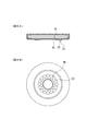
- FIG. 4A is a sectional view of the seal in FIG. 1
- FIG. 4B is a bottom view thereof.
- 4B is an enlarged cross-sectional view showing the contact state between the stay and the seal cut along the line AA in FIG. 4B
- FIG. 5A is a cross-sectional view when the annular protrusion is in contact with the seating surface
- FIG. FIG. 5A is a cross-sectional view when the annular protrusion is in contact with the seating surface
- FIG. 5C is a cross-sectional view showing a state immediately before the bellows cap is separated from the stay from the state shown in FIG. 5B.
- 6B is an enlarged cross-sectional view showing a contact state between the stay and the seal cut along the line BB in FIG. 4B
- FIG. 6A is a cross-sectional view when the annular protrusion comes into contact with the seating surface
- FIG. 6B is a cross-sectional view of FIG.
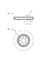
- FIG. 7A is sectional drawing
- FIG. 7B is a bottom view.
- FIG. 8A is sectional drawing
- FIG. 8B is a bottom view.
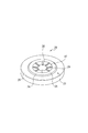
- FIG. 10 is a plan view of a stay in Embodiment 5.
- FIG. 11A is sectional drawing
- FIG. 11B is a bottom view.
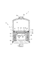
- FIG. 1 The accumulator according to the first embodiment will be described with reference to FIGS.
- the upper and lower sides of FIG. 1 will be described as the upper and lower sides of the accumulator.
- the accumulator 1 is a metal bellows type accumulator that uses a metal bellows 6 as a bellows, and mainly includes a housing 2, a metal bellows 6, a bellows cap 10, and a stay 30.
- the housing 2 is always partitioned into a gas chamber G in which high-pressure gas (for example, nitrogen gas) is sealed by a metal bellows 6 and a bellows cap 10 and a liquid chamber M in which a liquid (for example, brake fluid) is supplied. Yes.
- the gas chamber G is divided into the sealed liquid chamber Mc and the open liquid chamber Mo by the bellows cap 10 and the stay 30 when the hydraulic pressure in the pressure pipe (not shown) decreases.
- the housing 2 is configured by fixing (welding) a lid body 4 provided with an oil port 5 connected to a pressure pipe (not shown) to an opening of a bottomed cylindrical shell 3.
- the housing 2 is not limited to this structure.
- the lid 4 and the shell 3 may be integrated, and the bottom of the shell 3 may be a separate end cover from the shell 3.
- a gas injection port 3a for injecting gas into the gas chamber G is provided at the bottom of the shell 3 or a part corresponding thereto, and the gas plug 3b is closed after the gas injection.
- the metal bellows 6 has a fixed end 6 a fixed (welded) to the inner surface of the lid 4 and a disk-shaped bellows cap 10 fixed (welded) to the free end 6 b, and the accumulator 1 includes the metal bellows 6.
- the outer gas type accumulator is provided with a gas chamber G on the outer peripheral side.
- a guide 7 is attached to the outer periphery of the bellows cap 10 so that the metal bellows 6 and the bellows cap 10 do not contact the inner surface of the shell 3. The guide 7 does not exhibit a sealing action, and gas can be communicated in the vertical direction of the guide 7.
- the bellows cap 10 is formed in a disk shape with metal, and the outer peripheral edge 12 is hermetically fixed to the floating end 6b of the metal bellows 6 described above, and the gas chamber G and the liquid chamber M are sealed with the metal bellows 6 and the bellows cap 10. It is partitioned by state.
- the seal holder 13 is formed of a sheet metal, and an inward flange-shaped engagement portion 13b is integrally formed radially inward at one end (lower end) of a tubular attachment portion 13a, and the attachment portion 13a is integrally formed. While being attached to the lower surface of the bellows cap 10, an inwardly engaging portion 13b elastically presses and holds the seal 20 toward the bellows cap 10.
- the seal 20 covers the entire outer surface of a disk-shaped rigid plate 21 made of metal, hard resin, etc., and rubber 22 (elastic body) is covered by vulcanization adhesion.
- the outer peripheral edge portion of the seal 20 is held by the engaging portion 13 b of the seal holder 13.
- An annular protrusion 23 (elastic contact portion) that protrudes downward is formed on the lower side (oil port 5 side) of the rubber 22, and the annular protrusion 23 can contact and separate from the seating surface 35 of the stay 30. It is said that.
- the annular protrusion 23 includes a steep hypotenuse 24 that continues from an outer edge flat portion 29 that is located on the outermost side in the radial direction, a gentle hypotenuse 26 that continues from a central flat central portion 28 that is located on the innermost side in the radial direction,
- the cross-sectional shape includes a flat portion 25 that connects both the oblique sides 24 and 26.
- the oblique side parts 24 and 26 demonstrated the example where the radial direction inner side is gentle and the radial direction outer side is steep, it is not essential to set it as such an angle.
- Eight grooves 27 that extend radially in the radial direction and are arranged at equal intervals are formed in the oblique side portion 26.
- the groove 27 traverses the hypotenuse 26 and part of it extends to the center 28.
- the lower surface of the central portion 28 and the lower surface of the flat portion 29 belong to the same plane, but may belong to different planes. In short, both lower surfaces are positioned at a height lower than the annular protrusion 23 (in FIG. 5). Upper position).
- the number, width, and depth of the grooves can be changed as appropriate.
- the material of the elastic body is not limited to rubber, and may be elastic material such as resin.
- the stay 30 is a substantially cap-shaped structure made of metal, hard resin, or the like, and is mainly composed of a cylindrical rising portion 32, a bottom portion 34, and a through hole 33 provided in the center of the bottom portion 34. In the housing 2, it is arranged in a substantially inverted state. An end portion of the rising portion 32 is fixed to the lid body 4 in a liquid-tight manner by welding. The liquid can enter and exit through the through hole 33 between the sealed liquid chamber Mc and the open liquid chamber Mo.
- the upper surface of the bottom portion 34 is a seating surface 35 on which the annular projection 23 of the seal 20 is seated. When the annular protrusion 23 is seated on the seating surface 35, a sealing action is exerted to close the space between the sealed liquid chamber Mc and the open liquid chamber Mo in a liquid-tight manner.
- the accumulator 1 is connected to a pressure pipe of a device (not shown) at the oil port 5.
- a high-pressure fluid is introduced from the pressure pipe into the liquid chamber M
- the metal bellows 6 expands and the bellows cap 10 moves away from the stay 30. Yes.
- the oil port 5 communicates with the sealed liquid chamber Mc and the open liquid chamber Mo through the through-hole 33, and a liquid having a pressure at that time is introduced as needed from the oil port 5, and the bellows cap 10 is introduced with the introduced hydraulic pressure.
- the gas pressure enclosed in the gas chamber G moves from time to time so that the gas pressure is balanced.
- the bellows cap 10 is further pressed by the gas pressure.
- the annular protrusion 23 is crushed, and the hypotenuse part 24 and the hypotenuse part 26, which are buffer parts connected from the flat part 25, are also elastically deformed and come into contact with the seating surface 35. Contacts the seating surface 35 at a portion of the radial length L2 (FIGS. 5B and 6B).
- the annular protrusion 23 has the function of ensuring the sealing performance of the flat portion 25, and the oblique sides 24 and 26, particularly the oblique portion 26 having a large deformation amount, disperses the pressing force F by deformation. It functions as a buffer portion and has a function of suppressing mechanical damage to the seal 20 including the annular protrusion 23 and the rigid plate 21, the bellows cap 10, and the stay 30.
- the hypotenuse 26 As the seal 20 is lifted upward by the action of the hydraulic pressure, the hypotenuse 26 is gradually restored to its original shape, and the wedge-shaped space formed between the hypotenuse 26 and the seating surface 35 is zero-down.
- the groove 27 As the seal 20 is lifted upward, the groove 27 is released from the compressed state and gradually restored to its original shape, and the volume of the groove increases, so that the liquid acting on the groove 27 also increases.
- the pressure guiding portion 27A of the groove 27 is raised when the pressure in the pressure pipe is increased while the hypotenuse portion 26 (buffer portion) has a buffering action for protecting the flat portion 25 (sealing portion) with respect to the stay 30.
- Pressure is applied to the liquid existing in the (communication path), and the pushing force is instantaneously applied to the bellows cap 10, and the bellows cap 10 urged by the gas pressure can be quickly separated from the stay 30.
- the pressure guiding portion 27A (communication path) is formed in the hypotenuse portion 26 (buffer portion)
- the hypotenuse portion 26 (buffer portion) exhibits a buffering action by gas pressure at portions other than the pressure guiding portion 27A.
- the grooves 27 are arranged at equal intervals in the radial direction from the through holes 33 of the stay 30. For this reason, since the push-up force acts equally in the circumferential direction, the bellows cap 10 can be smoothly separated from the stay 30 without the bellows cap 10 being inclined due to the offset load. Further, since the groove 27 extends linearly and radially from the through hole 33 of the stay 30 toward the flat portion 25, the pushing force acts in the radial direction, and the bellows cap is smoothly separated from the stay. be able to.
- the seal 20 when used in a cold region, even when the annular protrusion 23 of the seal 20 is difficult to deform at the time of zero down, the seal 20 is more quickly separated from the stay 30 than the seal described as the prior art described above. be able to. This is presumably because the provision of the groove 27 makes it easier for liquid to be introduced into the groove 27, and the groove 27 becomes a fragile part and the oblique side part 26 is easily mechanically deformed. .
- the shape of the groove provided in the seal 20 is different from that in the first embodiment.
- the same structure as Example 1 and the overlapping structure are abbreviate
- the groove 40 in the second embodiment has eight grooves 41 in the radial direction (the same shape as the groove 27 in the first embodiment), and two annular grooves 42 and 43.
- the groove 41 is connected to the annular groove 42 and the annular groove 43 so that fluid can be conducted. Since the liquid guided from the radial direction through the groove 41 is also guided in the circumferential direction by the annular groove 42 and the annular groove 43, the bellows cap 10 can be quickly separated from the stay 30. . Further, the oblique side portion 26 is separated into segments in the radial direction and the circumferential direction by the groove 41 and the annular groove 42 or the annular groove 43, so that the oblique side portion 26 is easily mechanically deformed.
- channel divided in the circumferential direction may be sufficient.
- Embodiment 3 an accumulator according to Embodiment 3 will be described with reference to FIG.
- the third embodiment is different from the first embodiment in that the grooves provided in the seal 20 are replaced with dimples.
- the same structure as Example 1 and the overlapping structure are abbreviate
- a dimple 45 (communication path) is provided in the hypotenuse portion 26.
- most of the dimples 45 have a structure in which the hydraulic pressure can be confined with the seating surface 35 without communicating with the through hole 33 when zero down is performed. In this way, at the time of zero down, due to the liquid pressure of the confined liquid, a separation force in a direction to separate the seal 20 upward acts on the seal 20, and the seal 20 is more quickly removed from the stay 30. This can contribute to the separation.
- a protrusion may be employed.
- Embodiment 4 an accumulator according to Embodiment 4 will be described with reference to FIG.
- the fourth embodiment is different from the first embodiment in that the groove provided in the seal 20 is replaced with a protrusion.
- the same structure as Example 1 and the overlapping structure are abbreviate
- radially extending ridges 47 are provided on the hypotenuse portion 26. These protrusions 47 may be separate from the rubber 22, but it is desirable to integrally form the rubber 22 from the viewpoint of manufacturing workability in terms of strength.
- a communication path having a substantially triangular cross section communicating with the through hole 33 is formed between the rubber 22 of the seal 20 and the seating surface 35 at the time of zero down near both side surfaces of the protrusion 47.
- the pressure receiving area where the hydraulic pressure acts on the seal 20 is widened, and at the time of zero-down, a high stress is applied in the vicinity of the ridge 47 and the circumferential direction of the hypotenuse 26 is not improved. Since the uniform stress is applied, the hypotenuse 26 has a shape that is easily mechanically deformed. For this reason, the seal 20 can be quickly separated from the stay 30.
- the fifth embodiment is different from the first embodiment in that a stay 30 is used instead of the seal 20 as a member for providing a groove.
- a stay 30 is used instead of the seal 20 as a member for providing a groove.
- the same structure as Example 1 and the overlapping structure are abbreviate
- each groove 37 (communication paths) extending radially are provided on the upper surface side of the bottom 34 of the stay 30.
- the radial position where the groove 37 is provided is a position facing the oblique side portion 26 of the seal 20.
- the pressure receiving area where the hydraulic pressure acts on the seal 20 is widened when shifting from the zero down state to the steady operation state. For this reason, the seal 20 can be quickly separated from the stay 30.
- the annular protrusion 23 of the seal 20 does not have a discontinuous portion in the circumferential direction, so that the mechanical strength of the annular protrusion 23 is excellent.
- a groove 27 may be provided in the oblique side portion 26 of the seal 20.
- the groove 37 and the groove 27 may be arranged in the same position even if they are shifted in the circumferential direction. May be.
- Embodiment 6 an accumulator according to Embodiment 6 will be described with reference to FIG.
- the sixth embodiment is different from the first embodiment in that an annular groove is added to the flat portion 25 of the seal 20.
- the same structure as Example 1 and the overlapping structure are abbreviate
- annular grooves 50 are provided on the lower end side of the flat portion 25.
- the number of annular grooves 50 is not limited to three, and may be grooves that are discontinuous in the circumferential direction.
- the sealing portion of the annular protrusion 23 since the sealing portion of the annular protrusion 23 only needs to have a sealing function, the shape thereof does not necessarily have to be flat, and not only the shape in which the annular groove 50 is formed as shown in FIG.
- the cross section may be a curved surface.
- the annular protrusion 23 has been described as an example of the elastic contact portion.
- the elastic contact portion may be provided on the bellows cap 10 as long as it has a buffering action and a sealing function for buffering the force from the gas pressure.
- the rubber 22 is not limited to a shape having an annular protrusion.
- the shape of the seal portion is not limited to a flat shape, but may be another shape such as a curved surface, and the shape of the buffer portion is not limited to a shape having a hypotenuse. .
Priority Applications (4)
| Application Number | Priority Date | Filing Date | Title |
|---|---|---|---|
| CN201680071175.9A CN108368858B (zh) | 2016-01-13 | 2016-12-13 | 蓄能器 |
| JP2017561551A JP6763884B2 (ja) | 2016-01-13 | 2016-12-13 | アキュムレータ |
| EP16885084.0A EP3404271B1 (de) | 2016-01-13 | 2016-12-13 | Akkumulator |
| US15/778,996 US10480539B2 (en) | 2016-01-13 | 2016-12-13 | Accumulator |
Applications Claiming Priority (2)
| Application Number | Priority Date | Filing Date | Title |
|---|---|---|---|
| JP2016004743 | 2016-01-13 | ||
| JP2016-004743 | 2016-01-13 |
Publications (1)
| Publication Number | Publication Date |
|---|---|
| WO2017122481A1 true WO2017122481A1 (ja) | 2017-07-20 |
Family
ID=59311324
Family Applications (1)
| Application Number | Title | Priority Date | Filing Date |
|---|---|---|---|
| PCT/JP2016/087013 WO2017122481A1 (ja) | 2016-01-13 | 2016-12-13 | アキュムレータ |
Country Status (5)
| Country | Link |
|---|---|
| US (1) | US10480539B2 (de) |
| EP (1) | EP3404271B1 (de) |
| JP (1) | JP6763884B2 (de) |
| CN (1) | CN108368858B (de) |
| WO (1) | WO2017122481A1 (de) |
Families Citing this family (3)
| Publication number | Priority date | Publication date | Assignee | Title |
|---|---|---|---|---|
| JP6942149B2 (ja) | 2017-02-03 | 2021-09-29 | イーグル工業株式会社 | アキュムレータ |
| WO2018143030A1 (ja) * | 2017-02-03 | 2018-08-09 | イーグル工業株式会社 | アキュムレータ |
| WO2018143066A1 (ja) * | 2017-02-03 | 2018-08-09 | イーグル工業株式会社 | アキュムレータ |
Citations (3)
| Publication number | Priority date | Publication date | Assignee | Title |
|---|---|---|---|---|
| JP3148349U (ja) * | 2008-11-26 | 2009-02-12 | 日本発條株式会社 | アキュムレータ |
| JP2010112431A (ja) * | 2008-11-05 | 2010-05-20 | Nok Corp | アキュムレータ |
| JP2010151286A (ja) * | 2008-12-26 | 2010-07-08 | Nok Corp | 金属ベローズ式アキュムレータ |
Family Cites Families (16)
| Publication number | Priority date | Publication date | Assignee | Title |
|---|---|---|---|---|
| US2283439A (en) * | 1940-12-21 | 1942-05-19 | Vickers Inc | Accumulator diaphragm |
| US2543585A (en) * | 1945-01-13 | 1951-02-27 | Bendix Aviat Corp | Accumulator |
| JPH02266101A (ja) | 1989-04-05 | 1990-10-30 | Nhk Spring Co Ltd | アキュムレータ |
| DE59201216D1 (de) | 1991-04-16 | 1995-03-02 | Siemens Ag | Verfahren und Vorrichtung zur Überwachung des Betriebszustandes einer Dampfturbine. |
| EP1052412B1 (de) * | 1999-05-12 | 2005-03-09 | NHK Spring Co., Ltd. | Druckspeicher und dessen Herstellungsverfahren |
| EP1160460B1 (de) * | 2000-05-30 | 2003-11-12 | NHK Spring Co., Ltd. | Druckspeicher mit einem an das Gehäuse geschweissten Stutzen, einer Faltenbalgführung und einem Faltenbalgschutzelement |
| US6612339B1 (en) * | 2001-12-28 | 2003-09-02 | Kelsey-Hayes Company | Piston with fluid sealing ridges |
| JP3832579B2 (ja) * | 2002-05-21 | 2006-10-11 | Nok株式会社 | アキュムレータ |
| JP4131130B2 (ja) * | 2002-05-29 | 2008-08-13 | 株式会社アドヴィックス | ベローズ式液圧蓄圧器 |
| JP4384942B2 (ja) * | 2004-06-28 | 2009-12-16 | 日本発條株式会社 | アキュムレータ |
| JP5108733B2 (ja) * | 2008-11-27 | 2012-12-26 | Nok株式会社 | アキュムレータ |
| JP2010174985A (ja) * | 2009-01-29 | 2010-08-12 | Nhk Spring Co Ltd | アキュムレータへのガス封入方法 |
| US8523001B2 (en) * | 2009-12-07 | 2013-09-03 | Advanced Conservation Technology Distribution, Inc. | Thermal expansion/surge reduction water tank |
| CN103998792B (zh) * | 2012-06-11 | 2016-03-30 | 伊格尔工业股份有限公司 | 蓄能器 |
| CN104583606B (zh) * | 2013-02-15 | 2017-03-29 | 伊格尔工业股份有限公司 | 蓄能器 |
| JP5798646B2 (ja) * | 2014-02-24 | 2015-10-21 | 日本発條株式会社 | アキュムレータ |
-
2016
- 2016-12-13 US US15/778,996 patent/US10480539B2/en active Active
- 2016-12-13 CN CN201680071175.9A patent/CN108368858B/zh active Active
- 2016-12-13 EP EP16885084.0A patent/EP3404271B1/de active Active
- 2016-12-13 JP JP2017561551A patent/JP6763884B2/ja active Active
- 2016-12-13 WO PCT/JP2016/087013 patent/WO2017122481A1/ja unknown
Patent Citations (3)
| Publication number | Priority date | Publication date | Assignee | Title |
|---|---|---|---|---|
| JP2010112431A (ja) * | 2008-11-05 | 2010-05-20 | Nok Corp | アキュムレータ |
| JP3148349U (ja) * | 2008-11-26 | 2009-02-12 | 日本発條株式会社 | アキュムレータ |
| JP2010151286A (ja) * | 2008-12-26 | 2010-07-08 | Nok Corp | 金属ベローズ式アキュムレータ |
Non-Patent Citations (1)
| Title |
|---|
| See also references of EP3404271A4 * |
Also Published As
| Publication number | Publication date |
|---|---|
| US20180347597A1 (en) | 2018-12-06 |
| US10480539B2 (en) | 2019-11-19 |
| CN108368858A (zh) | 2018-08-03 |
| CN108368858B (zh) | 2020-01-14 |
| EP3404271A4 (de) | 2019-08-21 |
| EP3404271A1 (de) | 2018-11-21 |
| JP6763884B2 (ja) | 2020-09-30 |
| JPWO2017122481A1 (ja) | 2018-11-01 |
| EP3404271B1 (de) | 2021-01-27 |
Similar Documents
| Publication | Publication Date | Title |
|---|---|---|
| JP5102576B2 (ja) | アキュムレータ | |
| JP4905738B2 (ja) | アキュムレータ | |
| JP5474333B2 (ja) | アキュムレータ | |
| WO2017122481A1 (ja) | アキュムレータ | |
| JP5201722B2 (ja) | 金属ベローズ式アキュムレータ | |
| US7810522B1 (en) | Accumulator | |
| US9377031B2 (en) | Accumulator | |
| JP3148349U (ja) | アキュムレータ | |
| JP5279076B2 (ja) | 金属ベローズ式アキュムレータ | |
| JP5224323B2 (ja) | アキュムレータ | |
| JP4956362B2 (ja) | アキュムレータ | |
| WO2019008837A1 (ja) | 流体封入式防振装置 | |
| JP5016453B2 (ja) | アキュムレータ | |
| JP4956361B2 (ja) | アキュムレータ | |
| JP5116156B2 (ja) | 金属ベローズ式アキュムレータ | |
| JP5035907B2 (ja) | 金属ベローズ式アキュムレータ | |
| JP5348742B2 (ja) | ベローズ式アキュムレータ | |
| EP3578829B1 (de) | Akkumulator | |
| EP3252318B1 (de) | Hydraulischer akkumulator | |
| JPWO2017126354A1 (ja) | 金属ベローズ型アキュムレータ |
Legal Events
| Date | Code | Title | Description |
|---|---|---|---|
| 121 | Ep: the epo has been informed by wipo that ep was designated in this application |
Ref document number: 16885084 Country of ref document: EP Kind code of ref document: A1 |
|
| ENP | Entry into the national phase |
Ref document number: 2017561551 Country of ref document: JP Kind code of ref document: A |
|
| NENP | Non-entry into the national phase |
Ref country code: DE |