WO2017115490A1 - 遠心ファンの羽根車、その製造方法及び製造装置 - Google Patents
遠心ファンの羽根車、その製造方法及び製造装置 Download PDFInfo
- Publication number
- WO2017115490A1 WO2017115490A1 PCT/JP2016/073637 JP2016073637W WO2017115490A1 WO 2017115490 A1 WO2017115490 A1 WO 2017115490A1 JP 2016073637 W JP2016073637 W JP 2016073637W WO 2017115490 A1 WO2017115490 A1 WO 2017115490A1
- Authority
- WO
- WIPO (PCT)
- Prior art keywords
- main plate
- shroud
- blade
- shaft end
- blade shaft
- Prior art date
Links
Images


Classifications
-
- F—MECHANICAL ENGINEERING; LIGHTING; HEATING; WEAPONS; BLASTING
- F04—POSITIVE - DISPLACEMENT MACHINES FOR LIQUIDS; PUMPS FOR LIQUIDS OR ELASTIC FLUIDS
- F04D—NON-POSITIVE-DISPLACEMENT PUMPS
- F04D29/00—Details, component parts, or accessories
- F04D29/66—Combating cavitation, whirls, noise, vibration or the like; Balancing
- F04D29/661—Combating cavitation, whirls, noise, vibration or the like; Balancing especially adapted for elastic fluid pumps
- F04D29/666—Combating cavitation, whirls, noise, vibration or the like; Balancing especially adapted for elastic fluid pumps by means of rotor construction or layout, e.g. unequal distribution of blades or vanes
-
- F—MECHANICAL ENGINEERING; LIGHTING; HEATING; WEAPONS; BLASTING
- F04—POSITIVE - DISPLACEMENT MACHINES FOR LIQUIDS; PUMPS FOR LIQUIDS OR ELASTIC FLUIDS
- F04D—NON-POSITIVE-DISPLACEMENT PUMPS
- F04D29/00—Details, component parts, or accessories
- F04D29/02—Selection of particular materials
- F04D29/023—Selection of particular materials especially adapted for elastic fluid pumps
-
- B—PERFORMING OPERATIONS; TRANSPORTING
- B06—GENERATING OR TRANSMITTING MECHANICAL VIBRATIONS IN GENERAL
- B06B—METHODS OR APPARATUS FOR GENERATING OR TRANSMITTING MECHANICAL VIBRATIONS OF INFRASONIC, SONIC, OR ULTRASONIC FREQUENCY, e.g. FOR PERFORMING MECHANICAL WORK IN GENERAL
- B06B1/00—Methods or apparatus for generating mechanical vibrations of infrasonic, sonic, or ultrasonic frequency
- B06B1/02—Methods or apparatus for generating mechanical vibrations of infrasonic, sonic, or ultrasonic frequency making use of electrical energy
-
- B—PERFORMING OPERATIONS; TRANSPORTING
- B23—MACHINE TOOLS; METAL-WORKING NOT OTHERWISE PROVIDED FOR
- B23K—SOLDERING OR UNSOLDERING; WELDING; CLADDING OR PLATING BY SOLDERING OR WELDING; CUTTING BY APPLYING HEAT LOCALLY, e.g. FLAME CUTTING; WORKING BY LASER BEAM
- B23K20/00—Non-electric welding by applying impact or other pressure, with or without the application of heat, e.g. cladding or plating
- B23K20/10—Non-electric welding by applying impact or other pressure, with or without the application of heat, e.g. cladding or plating making use of vibrations, e.g. ultrasonic welding
- B23K20/106—Features related to sonotrodes
-
- B—PERFORMING OPERATIONS; TRANSPORTING
- B29—WORKING OF PLASTICS; WORKING OF SUBSTANCES IN A PLASTIC STATE IN GENERAL
- B29C—SHAPING OR JOINING OF PLASTICS; SHAPING OF MATERIAL IN A PLASTIC STATE, NOT OTHERWISE PROVIDED FOR; AFTER-TREATMENT OF THE SHAPED PRODUCTS, e.g. REPAIRING
- B29C65/00—Joining or sealing of preformed parts, e.g. welding of plastics materials; Apparatus therefor
- B29C65/02—Joining or sealing of preformed parts, e.g. welding of plastics materials; Apparatus therefor by heating, with or without pressure
- B29C65/08—Joining or sealing of preformed parts, e.g. welding of plastics materials; Apparatus therefor by heating, with or without pressure using ultrasonic vibrations
-
- B—PERFORMING OPERATIONS; TRANSPORTING
- B29—WORKING OF PLASTICS; WORKING OF SUBSTANCES IN A PLASTIC STATE IN GENERAL
- B29C—SHAPING OR JOINING OF PLASTICS; SHAPING OF MATERIAL IN A PLASTIC STATE, NOT OTHERWISE PROVIDED FOR; AFTER-TREATMENT OF THE SHAPED PRODUCTS, e.g. REPAIRING
- B29C65/00—Joining or sealing of preformed parts, e.g. welding of plastics materials; Apparatus therefor
- B29C65/78—Means for handling the parts to be joined, e.g. for making containers or hollow articles, e.g. means for handling sheets, plates, web-like materials, tubular articles, hollow articles or elements to be joined therewith; Means for discharging the joined articles from the joining apparatus
- B29C65/7802—Positioning the parts to be joined, e.g. aligning, indexing or centring
- B29C65/7805—Positioning the parts to be joined, e.g. aligning, indexing or centring the parts to be joined comprising positioning features
- B29C65/7814—Positioning the parts to be joined, e.g. aligning, indexing or centring the parts to be joined comprising positioning features in the form of inter-cooperating positioning features, e.g. tenons and mortises
-
- B—PERFORMING OPERATIONS; TRANSPORTING
- B29—WORKING OF PLASTICS; WORKING OF SUBSTANCES IN A PLASTIC STATE IN GENERAL
- B29C—SHAPING OR JOINING OF PLASTICS; SHAPING OF MATERIAL IN A PLASTIC STATE, NOT OTHERWISE PROVIDED FOR; AFTER-TREATMENT OF THE SHAPED PRODUCTS, e.g. REPAIRING
- B29C66/00—General aspects of processes or apparatus for joining preformed parts
- B29C66/01—General aspects dealing with the joint area or with the area to be joined
- B29C66/05—Particular design of joint configurations
- B29C66/20—Particular design of joint configurations particular design of the joint lines, e.g. of the weld lines
- B29C66/21—Particular design of joint configurations particular design of the joint lines, e.g. of the weld lines said joint lines being formed by a single dot or dash or by several dots or dashes, i.e. spot joining or spot welding
-
- B—PERFORMING OPERATIONS; TRANSPORTING
- B29—WORKING OF PLASTICS; WORKING OF SUBSTANCES IN A PLASTIC STATE IN GENERAL
- B29C—SHAPING OR JOINING OF PLASTICS; SHAPING OF MATERIAL IN A PLASTIC STATE, NOT OTHERWISE PROVIDED FOR; AFTER-TREATMENT OF THE SHAPED PRODUCTS, e.g. REPAIRING
- B29C66/00—General aspects of processes or apparatus for joining preformed parts
- B29C66/50—General aspects of joining tubular articles; General aspects of joining long products, i.e. bars or profiled elements; General aspects of joining single elements to tubular articles, hollow articles or bars; General aspects of joining several hollow-preforms to form hollow or tubular articles
- B29C66/51—Joining tubular articles, profiled elements or bars; Joining single elements to tubular articles, hollow articles or bars; Joining several hollow-preforms to form hollow or tubular articles
- B29C66/54—Joining several hollow-preforms, e.g. half-shells, to form hollow articles, e.g. for making balls, containers; Joining several hollow-preforms, e.g. half-cylinders, to form tubular articles
- B29C66/543—Joining several hollow-preforms, e.g. half-shells, to form hollow articles, e.g. for making balls, containers; Joining several hollow-preforms, e.g. half-cylinders, to form tubular articles joining more than two hollow-preforms to form said hollow articles
-
- B—PERFORMING OPERATIONS; TRANSPORTING
- B29—WORKING OF PLASTICS; WORKING OF SUBSTANCES IN A PLASTIC STATE IN GENERAL
- B29C—SHAPING OR JOINING OF PLASTICS; SHAPING OF MATERIAL IN A PLASTIC STATE, NOT OTHERWISE PROVIDED FOR; AFTER-TREATMENT OF THE SHAPED PRODUCTS, e.g. REPAIRING
- B29C66/00—General aspects of processes or apparatus for joining preformed parts
- B29C66/50—General aspects of joining tubular articles; General aspects of joining long products, i.e. bars or profiled elements; General aspects of joining single elements to tubular articles, hollow articles or bars; General aspects of joining several hollow-preforms to form hollow or tubular articles
- B29C66/65—General aspects of joining tubular articles; General aspects of joining long products, i.e. bars or profiled elements; General aspects of joining single elements to tubular articles, hollow articles or bars; General aspects of joining several hollow-preforms to form hollow or tubular articles with a relative motion between the article and the welding tool
-
- B—PERFORMING OPERATIONS; TRANSPORTING
- B29—WORKING OF PLASTICS; WORKING OF SUBSTANCES IN A PLASTIC STATE IN GENERAL
- B29C—SHAPING OR JOINING OF PLASTICS; SHAPING OF MATERIAL IN A PLASTIC STATE, NOT OTHERWISE PROVIDED FOR; AFTER-TREATMENT OF THE SHAPED PRODUCTS, e.g. REPAIRING
- B29C66/00—General aspects of processes or apparatus for joining preformed parts
- B29C66/70—General aspects of processes or apparatus for joining preformed parts characterised by the composition, physical properties or the structure of the material of the parts to be joined; Joining with non-plastics material
- B29C66/73—General aspects of processes or apparatus for joining preformed parts characterised by the composition, physical properties or the structure of the material of the parts to be joined; Joining with non-plastics material characterised by the intensive physical properties of the material of the parts to be joined, by the optical properties of the material of the parts to be joined, by the extensive physical properties of the parts to be joined, by the state of the material of the parts to be joined or by the material of the parts to be joined being a thermoplastic or a thermoset
- B29C66/739—General aspects of processes or apparatus for joining preformed parts characterised by the composition, physical properties or the structure of the material of the parts to be joined; Joining with non-plastics material characterised by the intensive physical properties of the material of the parts to be joined, by the optical properties of the material of the parts to be joined, by the extensive physical properties of the parts to be joined, by the state of the material of the parts to be joined or by the material of the parts to be joined being a thermoplastic or a thermoset characterised by the material of the parts to be joined being a thermoplastic or a thermoset
- B29C66/7392—General aspects of processes or apparatus for joining preformed parts characterised by the composition, physical properties or the structure of the material of the parts to be joined; Joining with non-plastics material characterised by the intensive physical properties of the material of the parts to be joined, by the optical properties of the material of the parts to be joined, by the extensive physical properties of the parts to be joined, by the state of the material of the parts to be joined or by the material of the parts to be joined being a thermoplastic or a thermoset characterised by the material of the parts to be joined being a thermoplastic or a thermoset characterised by the material of at least one of the parts being a thermoplastic
- B29C66/73921—General aspects of processes or apparatus for joining preformed parts characterised by the composition, physical properties or the structure of the material of the parts to be joined; Joining with non-plastics material characterised by the intensive physical properties of the material of the parts to be joined, by the optical properties of the material of the parts to be joined, by the extensive physical properties of the parts to be joined, by the state of the material of the parts to be joined or by the material of the parts to be joined being a thermoplastic or a thermoset characterised by the material of the parts to be joined being a thermoplastic or a thermoset characterised by the material of at least one of the parts being a thermoplastic characterised by the materials of both parts being thermoplastics
-
- B—PERFORMING OPERATIONS; TRANSPORTING
- B29—WORKING OF PLASTICS; WORKING OF SUBSTANCES IN A PLASTIC STATE IN GENERAL
- B29C—SHAPING OR JOINING OF PLASTICS; SHAPING OF MATERIAL IN A PLASTIC STATE, NOT OTHERWISE PROVIDED FOR; AFTER-TREATMENT OF THE SHAPED PRODUCTS, e.g. REPAIRING
- B29C66/00—General aspects of processes or apparatus for joining preformed parts
- B29C66/80—General aspects of machine operations or constructions and parts thereof
- B29C66/81—General aspects of the pressing elements, i.e. the elements applying pressure on the parts to be joined in the area to be joined, e.g. the welding jaws or clamps
- B29C66/814—General aspects of the pressing elements, i.e. the elements applying pressure on the parts to be joined in the area to be joined, e.g. the welding jaws or clamps characterised by the design of the pressing elements, e.g. of the welding jaws or clamps
- B29C66/8141—General aspects of the pressing elements, i.e. the elements applying pressure on the parts to be joined in the area to be joined, e.g. the welding jaws or clamps characterised by the design of the pressing elements, e.g. of the welding jaws or clamps characterised by the surface geometry of the part of the pressing elements, e.g. welding jaws or clamps, coming into contact with the parts to be joined
- B29C66/81427—General aspects of the pressing elements, i.e. the elements applying pressure on the parts to be joined in the area to be joined, e.g. the welding jaws or clamps characterised by the design of the pressing elements, e.g. of the welding jaws or clamps characterised by the surface geometry of the part of the pressing elements, e.g. welding jaws or clamps, coming into contact with the parts to be joined comprising a single ridge, e.g. for making a weakening line; comprising a single tooth
- B29C66/81429—General aspects of the pressing elements, i.e. the elements applying pressure on the parts to be joined in the area to be joined, e.g. the welding jaws or clamps characterised by the design of the pressing elements, e.g. of the welding jaws or clamps characterised by the surface geometry of the part of the pressing elements, e.g. welding jaws or clamps, coming into contact with the parts to be joined comprising a single ridge, e.g. for making a weakening line; comprising a single tooth comprising a single tooth
-
- B—PERFORMING OPERATIONS; TRANSPORTING
- B29—WORKING OF PLASTICS; WORKING OF SUBSTANCES IN A PLASTIC STATE IN GENERAL
- B29C—SHAPING OR JOINING OF PLASTICS; SHAPING OF MATERIAL IN A PLASTIC STATE, NOT OTHERWISE PROVIDED FOR; AFTER-TREATMENT OF THE SHAPED PRODUCTS, e.g. REPAIRING
- B29C66/00—General aspects of processes or apparatus for joining preformed parts
- B29C66/80—General aspects of machine operations or constructions and parts thereof
- B29C66/81—General aspects of the pressing elements, i.e. the elements applying pressure on the parts to be joined in the area to be joined, e.g. the welding jaws or clamps
- B29C66/814—General aspects of the pressing elements, i.e. the elements applying pressure on the parts to be joined in the area to be joined, e.g. the welding jaws or clamps characterised by the design of the pressing elements, e.g. of the welding jaws or clamps
- B29C66/8141—General aspects of the pressing elements, i.e. the elements applying pressure on the parts to be joined in the area to be joined, e.g. the welding jaws or clamps characterised by the design of the pressing elements, e.g. of the welding jaws or clamps characterised by the surface geometry of the part of the pressing elements, e.g. welding jaws or clamps, coming into contact with the parts to be joined
- B29C66/81433—General aspects of the pressing elements, i.e. the elements applying pressure on the parts to be joined in the area to be joined, e.g. the welding jaws or clamps characterised by the design of the pressing elements, e.g. of the welding jaws or clamps characterised by the surface geometry of the part of the pressing elements, e.g. welding jaws or clamps, coming into contact with the parts to be joined being toothed, i.e. comprising several teeth or pins, or being patterned
-
- B—PERFORMING OPERATIONS; TRANSPORTING
- B29—WORKING OF PLASTICS; WORKING OF SUBSTANCES IN A PLASTIC STATE IN GENERAL
- B29C—SHAPING OR JOINING OF PLASTICS; SHAPING OF MATERIAL IN A PLASTIC STATE, NOT OTHERWISE PROVIDED FOR; AFTER-TREATMENT OF THE SHAPED PRODUCTS, e.g. REPAIRING
- B29C66/00—General aspects of processes or apparatus for joining preformed parts
- B29C66/80—General aspects of machine operations or constructions and parts thereof
- B29C66/81—General aspects of the pressing elements, i.e. the elements applying pressure on the parts to be joined in the area to be joined, e.g. the welding jaws or clamps
- B29C66/814—General aspects of the pressing elements, i.e. the elements applying pressure on the parts to be joined in the area to be joined, e.g. the welding jaws or clamps characterised by the design of the pressing elements, e.g. of the welding jaws or clamps
- B29C66/8145—General aspects of the pressing elements, i.e. the elements applying pressure on the parts to be joined in the area to be joined, e.g. the welding jaws or clamps characterised by the design of the pressing elements, e.g. of the welding jaws or clamps characterised by the constructional aspects of the pressing elements, e.g. of the welding jaws or clamps
- B29C66/81463—General aspects of the pressing elements, i.e. the elements applying pressure on the parts to be joined in the area to be joined, e.g. the welding jaws or clamps characterised by the design of the pressing elements, e.g. of the welding jaws or clamps characterised by the constructional aspects of the pressing elements, e.g. of the welding jaws or clamps comprising a plurality of single pressing elements, e.g. a plurality of sonotrodes, or comprising a plurality of single counter-pressing elements, e.g. a plurality of anvils, said plurality of said single elements being suitable for making a single joint
-
- B—PERFORMING OPERATIONS; TRANSPORTING
- B29—WORKING OF PLASTICS; WORKING OF SUBSTANCES IN A PLASTIC STATE IN GENERAL
- B29C—SHAPING OR JOINING OF PLASTICS; SHAPING OF MATERIAL IN A PLASTIC STATE, NOT OTHERWISE PROVIDED FOR; AFTER-TREATMENT OF THE SHAPED PRODUCTS, e.g. REPAIRING
- B29C66/00—General aspects of processes or apparatus for joining preformed parts
- B29C66/80—General aspects of machine operations or constructions and parts thereof
- B29C66/83—General aspects of machine operations or constructions and parts thereof characterised by the movement of the joining or pressing tools
- B29C66/832—Reciprocating joining or pressing tools
- B29C66/8322—Joining or pressing tools reciprocating along one axis
-
- B—PERFORMING OPERATIONS; TRANSPORTING
- B29—WORKING OF PLASTICS; WORKING OF SUBSTANCES IN A PLASTIC STATE IN GENERAL
- B29C—SHAPING OR JOINING OF PLASTICS; SHAPING OF MATERIAL IN A PLASTIC STATE, NOT OTHERWISE PROVIDED FOR; AFTER-TREATMENT OF THE SHAPED PRODUCTS, e.g. REPAIRING
- B29C66/00—General aspects of processes or apparatus for joining preformed parts
- B29C66/80—General aspects of machine operations or constructions and parts thereof
- B29C66/84—Specific machine types or machines suitable for specific applications
- B29C66/843—Machines for making separate joints at the same time in different planes; Machines for making separate joints at the same time mounted in parallel or in series
- B29C66/8432—Machines for making separate joints at the same time mounted in parallel or in series
-
- F—MECHANICAL ENGINEERING; LIGHTING; HEATING; WEAPONS; BLASTING
- F04—POSITIVE - DISPLACEMENT MACHINES FOR LIQUIDS; PUMPS FOR LIQUIDS OR ELASTIC FLUIDS
- F04D—NON-POSITIVE-DISPLACEMENT PUMPS
- F04D29/00—Details, component parts, or accessories
- F04D29/26—Rotors specially for elastic fluids
- F04D29/28—Rotors specially for elastic fluids for centrifugal or helico-centrifugal pumps for radial-flow or helico-centrifugal pumps
- F04D29/281—Rotors specially for elastic fluids for centrifugal or helico-centrifugal pumps for radial-flow or helico-centrifugal pumps for fans or blowers
- F04D29/282—Rotors specially for elastic fluids for centrifugal or helico-centrifugal pumps for radial-flow or helico-centrifugal pumps for fans or blowers the leading edge of each vane being substantially parallel to the rotation axis
-
- F—MECHANICAL ENGINEERING; LIGHTING; HEATING; WEAPONS; BLASTING
- F04—POSITIVE - DISPLACEMENT MACHINES FOR LIQUIDS; PUMPS FOR LIQUIDS OR ELASTIC FLUIDS
- F04D—NON-POSITIVE-DISPLACEMENT PUMPS
- F04D29/00—Details, component parts, or accessories
- F04D29/26—Rotors specially for elastic fluids
- F04D29/28—Rotors specially for elastic fluids for centrifugal or helico-centrifugal pumps for radial-flow or helico-centrifugal pumps
- F04D29/30—Vanes
-
- F—MECHANICAL ENGINEERING; LIGHTING; HEATING; WEAPONS; BLASTING
- F04—POSITIVE - DISPLACEMENT MACHINES FOR LIQUIDS; PUMPS FOR LIQUIDS OR ELASTIC FLUIDS
- F04D—NON-POSITIVE-DISPLACEMENT PUMPS
- F04D29/00—Details, component parts, or accessories
- F04D29/60—Mounting; Assembling; Disassembling
- F04D29/62—Mounting; Assembling; Disassembling of radial or helico-centrifugal pumps
- F04D29/624—Mounting; Assembling; Disassembling of radial or helico-centrifugal pumps especially adapted for elastic fluid pumps
- F04D29/626—Mounting or removal of fans
-
- B—PERFORMING OPERATIONS; TRANSPORTING
- B29—WORKING OF PLASTICS; WORKING OF SUBSTANCES IN A PLASTIC STATE IN GENERAL
- B29L—INDEXING SCHEME ASSOCIATED WITH SUBCLASS B29C, RELATING TO PARTICULAR ARTICLES
- B29L2031/00—Other particular articles
- B29L2031/08—Blades for rotors, stators, fans, turbines or the like, e.g. screw propellers
Definitions
- the present invention relates to an impeller of a centrifugal fan, a manufacturing method and a manufacturing apparatus thereof, in particular, a plurality of blades arranged annularly around a rotation axis, and two blade shaft end portions which are both ends of the blade in the rotation axis direction side.
- the present invention relates to an impeller of a centrifugal fan, a manufacturing method thereof, and a manufacturing apparatus, which are formed by welding a main plate and a shroud disposed opposite to each other.
- a centrifugal fan may be used for air intake, supply, or discharge.
- the impeller constituting the centrifugal fan mainly includes a plurality of blades arranged in an annular shape around the rotation axis, and a main plate arranged so as to face two blade shaft end portions which are both ends of the blade in the rotation axis direction side. And a shroud.
- Patent Documents 1 and 2 Japanese Patent Laid-Open Nos. 2008-111393 and 2015-86827
- the blade shaft end on the main plate side of the blade and the main plate And between the shaft end on the shroud side of the blade and the shroud are ultrasonically welded.
- a main plate-side welded portion is formed between the main plate-side blade shaft end and the main plate
- a shroud-side welded portion is formed between the shroud-side blade shaft end and the shroud.
- the edge, the through hole, and the protrusion required for welding are increased in cost for the metal mold and molding process, the area of the welded portion is increased, and Due to the increase in size of ultrasonic horns and ultrasonic oscillators, it is difficult to manufacture an impeller for a centrifugal fan at low cost.
- An object of the present invention is to provide a plurality of blades that are annularly arranged around a rotation axis, and a main plate and a shroud that are arranged to face two blade shaft ends that are both ends on the rotation axis direction side of the blade.
- An object of the present invention is to be able to manufacture an impeller of a centrifugal fan that is welded to each other at low cost.
- the impeller of the centrifugal fan according to the first aspect has a plurality of blades, a main plate, and a shroud.
- the blade is annularly arranged around the rotation axis, and has two blade shaft end portions that are both ends on the rotation axis direction side.
- the main plate is disposed to face the main plate side blade shaft end which is one of the two blade shaft ends.
- the shroud is disposed to face the shroud side blade shaft end which is the other of the two blade shaft ends.
- the impeller of this centrifugal fan has a main plate side weld portion between the main plate side blade shaft end portion and the main plate, and has a shroud side weld portion between the shroud side blade shaft end portion and the shroud. is doing.
- the main plate-side welded portion is formed with a main plate-side weld hole, which is a recess that penetrates the main plate and reaches a part of the main plate-side blade shaft end portion, and the shroud-side welded portion has a shroud.
- a shroud-side welding hole which is a recess that penetrates to the shroud-side blade shaft end portion, is formed.
- a plurality of blades arranged annularly around the rotation axis, and a main plate and a shroud arranged opposite to the two blade shaft ends that are both ends of the blade in the rotation axis direction side are welded to each other.
- the number of molds and molding processes for forming edges, through-holes, and projections necessary for welding in advance are reduced, and the area of the welded portion is reduced. It is necessary to reduce the size and size of the ultrasonic horn and ultrasonic oscillator.
- a main plate-side weld portion having a main plate-side weld hole that is a recess that penetrates through the main plate and reaches a part of the end portion of the main plate-side blade shaft is formed and penetrates the shroud.
- a shroud-side weld portion having a shroud-side weld hole, which is a recess reaching the shroud-side blade shaft end is formed.
- a welded portion having such a weld hole can be obtained by ultrasonic welding using an ultrasonic horn having an insertion portion that passes through the main plate or shroud and reaches a part of the blade shaft end. Is possible.
- a shroud side ultrasonic horn having a shroud side insertion portion is used to apply ultrasonic vibration to the blade and the shroud to A shroud-side weld portion having a shroud-side weld hole by melting the shroud-side blade shaft end portion and the shroud so as to form a shroud-side weld hole that penetrates and reaches a part of the shroud-side blade shaft end portion.
- molding process for forming the edge, the through-hole, and protrusion which are required in the conventional ultrasonic welding in advance can be reduced, Can be reduced. Further, if the area of the welded portion is reduced, the ultrasonic horn can be reduced in size, and the output of the ultrasonic oscillator can be reduced.
- a plurality of blades arranged annularly around the rotation axis, and a main plate and a shroud arranged opposite to the two blade shaft ends that are both ends on the rotation axis direction side of the blades, It is possible to manufacture an impeller of a centrifugal fan that is welded to each other at low cost.
- the impeller of the centrifugal fan according to the second aspect is the impeller of the centrifugal fan according to the first aspect, wherein a plurality of main plate side welding holes are formed along the blade length direction of the main plate side blade shaft end. A plurality of shroud side welding holes are formed along the blade length direction of the shroud side blade shaft end.
- the welding between the main plate side blade shaft end and the main plate and between the shroud side blade shaft end and the shroud can be strengthened.
- the impeller of the centrifugal fan according to the third aspect is the impeller of the centrifugal fan according to the first or second aspect, wherein the main plate is a surface facing the main plate side blade shaft end, and the blade side main plate surface, And a non-blade side main plate surface that is a surface opposite to the rotation axis direction of the blade side main plate surface.
- a convex anti-blade side main plate convex portion is formed on the anti-blade side main plate surface corresponding to the main plate side blade shaft end portion
- a concave anti-blade side main plate convex portion is formed on the anti-blade side main plate convex portion.
- a blade side main plate concave portion is formed, and the main plate side welded portion is disposed in the anti-blade side main plate concave portion.
- the main plate side welding hole is opened on the surface opposite to the blade side main plate of the main plate, and a built-up portion is formed around the opening by melting of the main plate and the blade at the time of welding.
- a build-up portion protrudes in the direction of the rotation axis from the opposite side of the main plate surface of the main plate, and therefore, there is a possibility that it becomes a ventilation resistance during operation of the centrifugal fan and causes noise.
- a convex anti-blade side main plate convex portion is formed on the anti-blade side main plate surface corresponding to the main plate side blade shaft end portion, and a concave anti-blade side main plate convex portion is formed on the anti-blade side main plate convex portion.
- a blade side main plate recess is formed, and a main plate side weld is formed in the non-blade side main plate recess.
- the build-up portion formed around the main plate-side welding hole of the main plate-side welding portion is disposed in the counter-blade side main plate recess, and the rotation axis is more than the anti-blade-side main plate recess of the main plate. Although it protrudes in the direction, it can be suppressed to a protrusion below the anti-blade side main plate convex portion around the anti-blade side main plate concave portion.
- the impeller of the centrifugal fan according to the fourth aspect is the impeller of the centrifugal fan according to any of the first to third aspects.
- the shroud has a flat shroud corresponding to the end of the blade shaft on the shroud side.
- a flat plate portion is formed, and the shroud side welded portion is disposed on the shroud flat plate portion.
- the shroud is a bell-shaped member that is curved so that its diameter decreases as it moves away from the blade side in the direction of the rotation axis. Between the shroud curved plate portion and the shroud-side blade shaft end that form such a bell shape, the shroud It is not easy to weld.
- a flat shroud flat plate portion corresponding to the shroud side blade shaft end portion is formed on the shroud, and the shroud side blade shaft end portion and the shroud flat plate portion are welded to each other. By doing so, the shroud side welding part is obtained.
- the impeller of the centrifugal fan according to the fifth aspect is arranged such that the shroud flat plate portion corresponds to the vicinity of the center in the blade length direction of the shroud side blade shaft end in the centrifugal fan impeller according to the fourth aspect. Has been.
- the impeller of the centrifugal fan according to the sixth aspect is the impeller of the centrifugal fan according to the fourth or fifth aspect, wherein the shroud flat plate portion is arranged to face the rotation axis direction of the main plate-side welded portion. .
- the main plate When the ultrasonic vibration is applied to the blade and the main plate from the main plate side when the main plate side blade shaft end and the main plate are welded to each other, the main plate is pressed toward the shroud side. It is necessary to press the shroud toward the main plate so that the pressing force from the main plate side can be received.
- the shroud is a bell-shaped member that is curved so that its diameter decreases as it moves away from the blade side in the rotation axis direction, it is not easy to press the shroud appropriately toward the main plate side.
- the shroud flat plate portion formed for welding the shroud side blade shaft end portion and the shroud is arranged to face the rotation axis direction of the main plate side weld portion. I have to.
- the shroud flat plate portion Ultrasonic vibration can be applied to the blade and the main plate from the portion of the main plate facing the rotational axis direction of the shroud flat plate portion.
- the shroud flat plate portion faces the rotation axis direction of the main plate-side welded portion, and therefore, the portion of the shroud that requires the most pressing toward the main plate side can be appropriately pressed.
- An impeller of a centrifugal fan according to a seventh aspect is the impeller of the centrifugal fan according to any of the first to sixth aspects, wherein the shroud is a surface facing the shroud side blade shaft end. And an anti-blade side shroud surface which is a surface opposite to the rotation axis direction of the blade side shroud surface. And here, the shroud flat surface which consists of a flat surface is formed in the anti-blade side shroud surface facing the rotation-axis direction of the main-plate side welding part.
- the main plate When the ultrasonic vibration is applied to the blade and the main plate from the main plate side when the main plate side blade shaft end and the main plate are welded to each other, the main plate is pressed toward the shroud side. It is necessary to press the shroud toward the main plate so that the pressing force from the main plate side can be received.
- the shroud is a bell-shaped member that is curved so that its diameter decreases as it moves away from the blade side in the rotation axis direction, it is not easy to press the shroud appropriately toward the main plate side.
- a shroud flat surface made of a flat surface is formed on the anti-blade side shroud surface of the shroud so as to face the rotational axis direction of the main plate side welded portion.
- the impeller of the centrifugal fan according to the eighth aspect is the impeller of the centrifugal fan according to any of the first to seventh aspects, wherein the blade on the main plate side blade shaft end or the main plate has a blade more than the main plate side weld portion.
- a non-welded portion for ensuring a gap between the main plate side blade shaft end portion and the main plate is formed in a portion on the blade trailing edge side.
- the main plate side welding shaft is welded between the main plate side blade shaft end and the main plate to form a main plate side welding portion.
- the blade trailing edge side portion of the main plate side welding portion is also weakly welded. There is a risk. And if it is weakly welded at the blade trailing edge side of the main plate-side welded portion, such a weakly welded portion may be detached during operation of the centrifugal fan, and noise may be generated.
- a gap is secured between the main plate and the portion on the blade trailing edge side of the main plate side blade shaft end portion by the non-welded portion.
- the impeller of the centrifugal fan according to the ninth aspect is the impeller of the centrifugal fan according to any of the first to eighth aspects, wherein the main plate is along the blade trailing edge side portion of the main plate side blade shaft end.
- a dam portion is formed as described above.
- the main plate and the blade are melted when the main plate side blade shaft end and the main plate are welded. At this time, such a melt is generated between the main plate side and the portion of the main plate side blade shaft end on the blade trailing edge side and the main plate. Outflow can be suppressed by the weir part.
- a manufacturing method of an impeller for a centrifugal fan which is opposed to a plurality of blades arranged annularly around a rotation axis, and two blade shaft ends that are both ends of the blade in the rotation axis direction side. And a main plate and a shroud which are arranged in the same manner.
- the main plate side blade shaft end and one of the two blade shaft end portions are mutually connected, and the shroud side blade shaft is the other of the two blade shaft end portions.
- the following welding technique is employed.
- a plurality of blades arranged annularly around the rotation axis, and a main plate and a shroud arranged opposite to the two blade shaft ends that are both ends of the blade in the rotation axis direction side are welded to each other.
- the number of molds and molding processes for forming edges, through-holes, and projections necessary for welding in advance are reduced, and the area of the welded portion is reduced. It is necessary to reduce the size and size of the ultrasonic horn and ultrasonic oscillator.
- the welding hole formed by such an ultrasonic welding method constitutes a welding portion between the blade and the main plate or the shroud, and passes through the main plate or the shroud until reaching a part of the blade shaft end portion. It can be obtained by using an ultrasonic horn having an insertion part to be inserted.
- a shroud side ultrasonic horn having a shroud side insertion portion is used to apply ultrasonic vibration to the blade and the shroud to A shroud-side weld portion having a shroud-side weld hole by melting the shroud-side blade shaft end portion and the shroud so as to form a shroud-side weld hole that penetrates and reaches a part of the shroud-side blade shaft end portion.
- molding process for forming the edge, the through-hole, and protrusion which are required in the conventional ultrasonic welding in advance can be reduced, Can be reduced. Further, if the area of the welded portion is reduced, the ultrasonic horn can be reduced in size, and the output of the ultrasonic oscillator can be reduced.
- a plurality of blades arranged annularly around the rotation axis, and a main plate and a shroud arranged opposite to the two blade shaft ends that are both ends on the rotation axis direction side of the blades, It is possible to manufacture an impeller of a centrifugal fan that is welded to each other at low cost.
- the manufacturing method of the impeller of the centrifugal fan according to the eleventh aspect is the manufacturing method of the impeller of the centrifugal fan according to the tenth aspect, wherein the main plate side welding hole is along the blade length direction of the main plate side blade shaft end.
- the blade and the shroud are formed so that a plurality of shroud-side welding holes are formed along the blade length direction of the shroud-side blade shaft end portion by applying ultrasonic vibration to the blade and the main plate so as to be formed in plural. Apply ultrasonic vibration to
- the welding between the main plate side blade shaft end and the main plate and between the shroud side blade shaft end and the shroud can be strengthened.
- the centrifugal fan impeller according to the twelfth aspect is the centrifugal fan impeller according to the tenth or eleventh aspect, wherein the main plate side blade shaft end portion and the main plate are mutually connected, and Welding between the shroud side blade shaft end and the shroud is sequentially performed on each of the plurality of blades.
- an ultrasonic horn for performing welding between the main plate side blade shaft end portion and the main plate and between the shroud side blade shaft end portion and the shroud any one of a plurality of blades and the main plate are used.
- an ultrasonic horn for welding with the shroud may be prepared.
- the ultrasonic horn can be further reduced in size. Can be further reduced.
- a centrifugal fan impeller according to a thirteenth aspect is the centrifugal fan impeller according to any of the tenth to twelfth aspects, wherein the main plate side blade shaft is disposed on the opposite side of the main plate of the main plate.
- a convex anti-blade side main plate convex portion is formed corresponding to the end portion
- a concave anti-blade side main plate concave portion is formed on the anti-blade side main plate convex portion
- a gap between the main plate side blade shaft end portion and the main plate is formed.
- the main plate has a blade side main plate surface which is a surface facing the main plate side blade shaft end portion, and an anti-blade side main plate surface which is a surface opposite to the rotation axis direction of the blade side main plate surface.
- the main plate side welding hole is opened on the surface opposite to the blade side main plate of the main plate, and a built-up portion is formed around the opening by melting of the main plate and the blade at the time of welding.
- a build-up portion protrudes in the direction of the rotation axis from the opposite side of the main plate surface of the main plate, and therefore, there is a possibility that it becomes a ventilation resistance during operation of the centrifugal fan and causes noise.
- a convex anti-blade side main plate convex portion is formed on the anti-blade side main plate surface corresponding to the main plate side blade shaft end portion, and a concave anti-blade side main plate convex portion is formed on the anti-blade side main plate convex portion.
- a blade-side main plate recess is formed, and the main plate-side welded portion is formed by applying ultrasonic vibration from the opposite blade-side main plate recess.
- the build-up portion formed around the main plate-side welding hole of the main plate-side welding portion is disposed in the counter-blade side main plate recess, and the rotation axis is more than the anti-blade-side main plate recess of the main plate. Although it protrudes in the direction, it can be suppressed to a protrusion below the anti-blade side main plate convex portion around the anti-blade side main plate concave portion.
- a centrifugal fan impeller according to a fourteenth aspect is the centrifugal fan impeller according to any of the tenth to thirteenth aspects, wherein the shroud corresponds to the shroud side blade shaft end.
- the shroud is a bell-shaped member that is curved so that its diameter decreases as it moves away from the blade side in the direction of the rotation axis. Between the shroud curved plate portion and the shroud-side blade shaft end that form such a bell shape, the shroud It is not easy to weld.
- a flat shroud flat plate portion corresponding to the shroud blade shaft end portion is formed on the shroud, and ultrasonic vibration is applied from the shroud flat plate portion to the blade and the shroud.
- the shroud side welded portion is formed by welding the shroud side blade shaft end portion and the shroud flat plate portion.
- the centrifugal fan impeller according to the fifteenth aspect is the centrifugal fan impeller manufacturing method according to the fourteenth aspect, wherein the shroud flat plate portion is located near the center of the shroud side blade shaft end in the blade length direction.
- ultrasonic vibration is applied to the shroud flat plate portion and the center of the shroud blade shaft end near the center in the blade length direction.
- a centrifugal fan impeller according to a sixteenth aspect is the centrifugal fan impeller according to the fourteenth or fifteenth aspect, wherein the main plate side blade shaft end and the main plate are welded to each other. In doing so, ultrasonic vibration is applied to the blade and the main plate from the portion of the main plate facing the rotational axis direction of the shroud flat plate portion while pressing the shroud flat plate portion toward the main plate side.
- the main plate When the ultrasonic vibration is applied to the blade and the main plate from the main plate side when the main plate side blade shaft end and the main plate are welded to each other, the main plate is pressed toward the shroud side. It is necessary to press the shroud toward the main plate so that the pressing force from the main plate side can be received.
- the shroud is a bell-shaped member that is curved so that its diameter decreases as it moves away from the blade side in the rotation axis direction, it is not easy to press the shroud appropriately toward the main plate side.
- the shroud flat plate portion formed for welding the shroud side blade shaft end portion and the shroud.
- the ultrasonic vibration is applied to the blade and the main plate from the portion of the main plate facing the rotation axis direction of the shroud flat plate portion.
- Ultrasonic vibration can be applied to the blade and the main plate from the portion of the main plate facing the rotational axis direction of the shroud flat plate portion.
- the shroud flat plate portion faces the rotation axis of the portion of the main plate that imparts ultrasonic vibration to the blade and the main plate, so the portion of the shroud that requires the most pressing to the main plate side is selected. It can be pressed properly.
- a centrifugal fan impeller according to a seventeenth aspect is the centrifugal fan impeller manufacturing method according to any of the tenth to sixteenth aspects, wherein the shroud has a flat surface on the side opposite to the blade shroud.
- the shroud has a flat surface on the side opposite to the blade shroud.
- the shroud includes a blade-side shroud surface that is a surface facing the shroud-side blade shaft end portion, and an anti-blade-side shroud surface that is a surface opposite to the rotational axis direction of the blade-side shroud surface.
- the main plate When the ultrasonic vibration is applied to the blade and the main plate from the main plate side when the main plate side blade shaft end and the main plate are welded to each other, the main plate is pressed toward the shroud side. It is necessary to press the shroud toward the main plate so that the pressing force from the main plate side can be received.
- the shroud is a bell-shaped member that is curved so that its diameter decreases as it moves away from the blade side in the rotation axis direction, it is not easy to press the shroud appropriately toward the main plate side.
- the shroud flat surface is formed on the shroud surface of the shroud, and the flat surface of the shroud is pressed to the main plate side to weld the main plate side blade shaft end to the main plate.
- ultrasonic vibration is applied to the blade and the main plate from the portion of the main plate facing the rotational axis direction of the shroud flat surface.
- a centrifugal fan impeller manufacturing method according to any one of the tenth to seventeenth aspects, wherein the main plate side blade shaft end portion and the main plate are disposed between each other. Is welded to the blade and the main plate from the blade front edge side of the main plate with a gap secured between the main plate and the blade trailing edge side portion of the main plate side blade shaft end. Apply vibration.
- the main plate side weld portion is formed when the main plate side blade shaft end and the main plate are welded to each other. At this time, such main plate side weld is formed. Ultrasonic vibration is also transmitted to the portion on the blade trailing edge side than the portion, and there is a possibility that the blade is weakly welded. And if it is weakly welded at the blade trailing edge side of the main plate-side welded portion, such a weakly welded portion may be detached during operation of the centrifugal fan, and noise may be generated.
- An impeller manufacturing apparatus for a centrifugal fan faces a plurality of blades arranged annularly around a rotation axis and two blade shaft ends that are both ends of the blade in the rotation axis direction side.
- This is an apparatus for manufacturing an impeller of a centrifugal fan in which the main plate and the shroud that are arranged in this manner are welded to each other.
- the centrifugal fan impeller manufacturing apparatus applies ultrasonic vibration to the blade and the main plate in order to weld the main plate side blade shaft end and one of the two blade shaft ends.
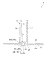
- the main plate-side ultrasonic horn has a main plate-side insertion portion inserted through the main plate until reaching a part of the main plate-side blade shaft end, and the shroud-side ultrasonic horn is shroud And a shroud side insertion portion that is inserted until reaching a part of the shroud side blade shaft end portion.
- a plurality of blades arranged annularly around the rotation axis, and a main plate and a shroud arranged opposite to the two blade shaft ends that are both ends of the blade in the rotation axis direction side are welded to each other.
- the number of molds and molding processes for forming edges, through-holes, and projections necessary for welding in advance are reduced, and the area of the welded portion is reduced. It is necessary to reduce the size and size of the ultrasonic horn and ultrasonic oscillator.
- a main plate side ultrasonic horn that applies ultrasonic vibrations to the blade and the main plate in order to weld the main plate side blade shaft end portion to the main plate, penetrates the main plate.
- the main plate side insertion portion is inserted until reaching a part of the main plate side blade shaft end portion.
- a shroud ultrasonic horn that applies ultrasonic vibrations to the blade and the shroud is passed through the shroud and the shroud blade shaft end The shroud side insertion portion is inserted until reaching a part.
- the main plate-side ultrasonic horn having such a main plate-side insertion portion is a main plate which is a recess that gives ultrasonic vibration to the blade and the main plate and penetrates the main plate to reach a part of the main plate-side blade shaft end.
- the main plate side blade shaft end portion and the main plate are melted so that the side weld hole is formed, thereby forming the main plate side weld portion having the main plate side weld hole.
- the shroud-side ultrasonic horn having such a shroud-side insertion portion is a recess that imparts ultrasonic vibrations to the blade and the shroud and reaches a part of the shroud-side blade shaft end through the shroud.
- the shroud side blade shaft end portion and the shroud are melted so that a certain shroud side weld hole is formed, thereby forming a shroud side weld portion having a shroud side weld hole.
- molding process for forming the edge, the through-hole, and protrusion which are required in the conventional ultrasonic welding in advance can be reduced, Can be reduced.
- the ultrasonic horn can be reduced in size, and the output of the ultrasonic oscillator can be reduced.
- a plurality of blades arranged annularly around the rotation axis, and a main plate and a shroud arranged opposite to the two blade shaft ends that are both ends on the rotation axis direction side of the blades, It is possible to manufacture an impeller of a centrifugal fan that is welded to each other at low cost.
- the centrifugal fan impeller manufacturing apparatus is the centrifugal fan impeller manufacturing apparatus according to the nineteenth aspect, wherein the main plate-side ultrasonic horn has the main plate-side insertion portion as the main plate-side blade shaft end portion.
- the shroud-side ultrasonic horn has a plurality of shroud-side insertion portions along the blade length direction of the shroud-side blade shaft end.
- the welding between the main plate side blade shaft end and the main plate and between the shroud side blade shaft end and the shroud can be strengthened.
- the centrifugal fan impeller manufacturing apparatus is the centrifugal fan impeller manufacturing apparatus according to the nineteenth or twentieth aspect, wherein the main plate side ultrasonic horn and the shroud side ultrasonic horn include a plurality of centrifugal fan impellers. One of the blades is welded to the main plate and the shroud.
- the centrifugal fan impeller manufacturing apparatus is configured so that any one of a plurality of blades can be aligned with the main plate-side ultrasonic horn and the shroud-side ultrasonic horn. It further has an impeller support device that supports the blade and the shroud so as to be rotatable about the rotation axis.
- the welding between the main plate side blade shaft end and the main plate and between the shroud side blade shaft end and the shroud can be sequentially performed on each of the plurality of blades. become.
- the ultrasonic horn can be further reduced in size. Can be further reduced.
- a centrifugal fan impeller manufacturing apparatus is the centrifugal fan impeller manufacturing apparatus according to any one of the nineteenth to twenty-first aspects.
- a shroud pressing device that presses the shroud toward the main plate is further provided.
- the main plate When welding the main plate side blade shaft end to the main plate, the main plate is pressed toward the shroud by the main plate side ultrasonic horn when applying ultrasonic vibration to the blade and main plate from the main plate side. Will be.
- the shroud when welding between the main plate side blade shaft end and the main plate, the shroud can be pressed toward the main plate side, and the pressing force from the main plate side by the main plate side ultrasonic horn is received. be able to.
- a centrifugal fan impeller manufacturing apparatus is the centrifugal fan impeller manufacturing apparatus according to the twenty-second aspect, wherein the shroud pressing device is the main plate side blade and the main plate side blade of the shroud. A portion opposed to the rotation axis direction of the portion inserted into the shaft end portion is pressed toward the main plate.
- a centrifugal fan impeller manufacturing apparatus is the centrifugal fan impeller manufacturing apparatus according to any of the nineteenth to twenty-third aspects, wherein the main plate-side blade shaft end portion is driven by the main-plate-side ultrasonic horn.
- the blade end edge side portion of the main plate and the main plate side insertion portion of the main plate are inserted into the main plate and the main plate side blade shaft end portion.
- the apparatus further includes a non-welding device that bends and deforms the main plate so that a gap is secured between the rear edge portion and the rear edge portion.
- the main plate side weld is inserted into the portion where the main plate side insertion portion of the main plate side ultrasonic horn is inserted.
- the ultrasonic vibration is also transmitted to the blade trailing edge side portion of the main plate side welding portion, and there is a possibility of weak welding.
- it is weakly welded at the blade trailing edge side of the main plate-side welded portion, such a weakly welded portion may be detached during operation of the centrifugal fan, and noise may be generated.
- the main plate when welding the main plate side blade shaft end and the main plate, the main plate is bent and deformed using a non-welding device, so that the main plate side blade shaft end In a state where a gap is secured between the edge side portion and the main plate, ultrasonic vibration is applied to the blade and the main plate from the blade leading edge side portion of the main plate rather than the gap.
- FIG. 4 is a view taken along arrow A in FIG. 3 (shown excluding a part of the shroud).
- FIG. 4 is a view (shown excluding a part of the main plate) in FIG. It is the figure which expanded the C section of FIG. It is the figure which expanded the D section of FIG. It is a figure which shows the II cross section of FIG.6 and FIG.7. It is a figure which shows the II-II cross section and III-III cross section of FIG.
- FIG. 8 is a view showing a IV-IV section and a VV section in FIG. 7. It is the expanded sectional view which looked at the E section of Drawing 7 from the pressure side. It is a figure which shows the VI-VI cross section of FIG.
- It is a schematic plan view of the manufacturing apparatus of an impeller. It is a schematic side view of the manufacturing apparatus of an impeller. It is a schematic front view (illustration is remove
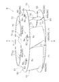
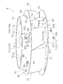
- FIG. 1 is an external perspective view (ceiling is omitted) of an air conditioner 1 in which a centrifugal fan 4 including an impeller 8 according to an embodiment of the present invention is employed.
- the air conditioner 1 is a ceiling-mounted air conditioner, and mainly includes a casing 2 that houses various components therein, and a decorative panel 3 that is disposed below the casing 2. ing.
- the casing 2 of the air conditioner 1 is a box-shaped member having an open bottom surface, and is inserted into an opening formed in the ceiling of the air conditioning room, as shown in FIG. 2 (a schematic side sectional view of the air conditioner 1). Has been placed. And the decorative panel 3 surrounds the outer periphery of the inlet 3a arranged in the substantially center for inhaling the air of the air conditioning room into the casing 2 and the inlet 3a for blowing the air from the casing 2 to the air conditioning room.
- the air outlet 3b is disposed so as to be fitted in the opening of the ceiling.
- a centrifugal fan 4 that mainly sucks air in the air-conditioned room into the casing 2 through the suction port 3 a of the decorative panel 3 and blows it out in the outer peripheral direction, a heat exchanger 5 surrounding the outer periphery of the centrifugal fan 4, A bell mouth 6 for guiding the air sucked from the suction port 3a to the centrifugal fan 4 is arranged.
- the centrifugal fan 4 includes a fan motor 7 provided in the approximate center of the top plate 2 a of the casing 2, and an impeller 8 that is connected to the fan motor 7 and is driven to rotate.
- the air conditioning apparatus 1 provided with the centrifugal fan 4 is not limited to the ceiling-mounted type, but may be another type.
- the structure of the impeller 8, the manufacturing method of the impeller 8, and the manufacturing apparatus of the impeller 8 are mentioned later.
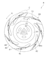
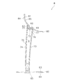
- FIG. 3 is an external perspective view of the impeller 8.
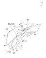
- FIG. 4 is a view taken in the direction of arrow A in FIG. 3 (shown excluding a part of the shroud 80).
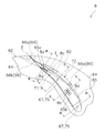
- 5 is a view taken in the direction of arrow B in FIG. 3 (illustrated excluding a part of the main plate 60).
- FIG. 6 is an enlarged view of a portion C in FIG.
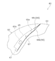
- FIG. 7 is an enlarged view of a portion D in FIG.
- FIG. 10 is a view of a part of the main plate 60 as viewed from the blade 70 side of the rotation axis O direction.
- FIG. 11 is a view showing the IV-IV section and the VV section of FIG. 12 is an enlarged cross-sectional view of the portion E in FIG. 7 as viewed from the pressure surface side.
- 13 is a cross-sectional view taken along the line VI-VI in FIG.
- the impeller 8 is mainly composed of a disk-shaped main plate 60 connected to the fan motor 7 and a plurality of (here, 7) annularly arranged around the rotation axis O of the main plate 60 on the side opposite to the fan motor 7 of the main plate 60.
- a plurality of blades 70, and an annular shroud 80 disposed so as to sandwich the plurality of blades 70 between the main plate 60 and the rotation axis O direction.
- the rotation direction of the impeller 8 is R.
- the main plate 60 is a resin member formed at the center thereof so that a substantially conical hub portion 61 protrudes toward the suction port 3a.
- the hub portion 61 is formed with a plurality of (in this case, three) cooling air holes 62 formed of long holes formed side by side on the concentric circle of the main plate 60.
- the shroud 80 is a bell-shaped resin member that protrudes while curving toward the suction port 3a as it goes from the outer periphery to the center opening.
- the resin material constituting the shroud 80 is not particularly limited, but here, the same resin material as that of the main plate 60 is used. Further, a bell-shaped portion of the shroud 80 is referred to as a shroud curved plate portion 81.
- the blade 70 is a resin member formed separately from the main plate 60 and the shroud 80.
- the resin material constituting the blade 70 is not particularly limited, but here, the same resin material as that of the main plate 60 and the shroud 80 is used.
- One end of the blade 70 on the side of the rotation axis O direction is a main plate side blade shaft end 71 disposed to face the main plate 60, and is fixed to the main plate 60.
- the other end of the blade 70 on the side of the rotation axis O direction is a shroud side blade shaft end 72 disposed to face the shroud 80 and is fixed to the shroud 80.
- the blade 70 has a blade shape in which the main plate side blade shaft end portion 71 is inclined backward relative to the shroud side blade shaft end portion 72 when the impeller 8 is viewed along the rotation axis O direction.
- the blade shaft end portions 71 and 72 are formed to intersect each other. That is, the blade 70 has a three-dimensional wing shape extending in the direction of the rotation axis O while twisting between the main plate 60 and the shroud 80.
- the blade 70 is mainly a hollow blade having a blade main body 73 and a blade lid 74 that is fitted into the blade main body 73 by being fitted into the blade main body 73 and forms a hollow space S between the blade main body 73 and the blade. The weight of 70 is reduced.
- the hollowing of the blade 70 is not based on the fitting structure of the two members 73 and 74 but may be based on blow molding or the like.
- the uneven shape for improving the performance of the centrifugal fan 4 is formed at the blade trailing edge portion of the blade 70.
- it is not always necessary. It does not have to be formed.
- the main plate side blade shaft end portion 71 of the blade 70 is fixed to the main plate 60 by welding the main plate side blade shaft end portion 71 and the main plate 60, and the welded portion is the main plate side weld portion. 8a and 8b are formed.
- the first main plate-side weld portion 8a is disposed corresponding to the portion of the main plate-side blade shaft end portion 71 near the blade trailing edge in the blade length direction
- the second main plate-side weld portion 8b is the main plate-side blade shaft end portion.
- the portion 71 is disposed corresponding to the portion near the blade leading edge in the blade length direction.
- Main plate side welded portions 8a and 8b are each formed with a main plate side weld hole 8d which is a recess penetrating the main plate 60 and reaching a part of the main plate side blade shaft end portion 71.
- a plurality (three in this case) of main plate side welding holes 8d are formed along the blade length direction of the main plate side blade shaft end portion 71 with respect to each of the main plate side welding portions 8a and 8b.
- the number of main plate side welds 8a and 8b is not limited to two, and the number of main plate side weld holes 8d is not limited to three.
- the main plate 60 has a blade-side main plate surface 63 that is a surface facing the main plate-side blade shaft end portion 71 and an anti-blade side main plate surface 64 that is a surface on the opposite side of the blade-side main plate surface 63 in the rotation axis O direction. And have.
- the anti-blade side main plate surface 64 is formed with a convex anti-blade side main plate convex portion 65 corresponding to the main plate side blade shaft end portion 71, and the anti-blade side main plate convex portion 65 has The concave anti-blade side main plate concave portions 65a and 65b are formed, and the main plate side weld portions 8a and 8b are disposed in the anti-blade side main plate concave portions 65a and 65b.
- the first blade side main plate concave portion 65a is disposed corresponding to the first main plate side welded portion 8a
- the second blade side main plate concave portion 65b is disposed corresponding to the second main plate side welded portion 8b.
- the portion corresponding to the main plate side blade shaft end portion 71 of the main plate 60 has a slightly larger plate thickness than the surrounding portion, and the plate thickness is reduced for a part of the portion where the plate thickness is increased.
- the main plate-side welded portions 8a and 8b are arranged in the portion where the plate thickness is reduced. Therefore, the main plate side welded portions 8a and 8b are overlapped with the main plate side blade shaft end portion 71 and the portion of the main plate 60 where the anti-blade side main plate concave portions 65a and 65b are arranged in the rotation axis O direction.
- the main plate side welding hole 8d is formed so as to penetrate the main plate 60 and reach the main plate side blade shaft end portion 71.
- a gap is secured between the main plate side blade shaft end portion 71 and the main plate 60 in a portion on the blade trailing edge side of the blade 70 with respect to the first main plate side weld portion 8 a.
- the non-welded portion 8f is formed.
- the non-welded portion 8f is a portion having a shape such that a portion of the blade trailing edge portion of the main plate side blade shaft end portion 71 facing the blade side main plate surface 63 is cut out.
- the non-welded portion 8f is not limited to that formed at the blade trailing edge portion of the main plate side blade shaft end portion 71.
- the non-welded portion 8f is formed at the outer peripheral edge portion of the main plate side blade shaft end portion 71 of the main plate 60.
- the main plate side blade shaft end portion 71 may be a portion having a shape in which a portion facing the blade trailing edge is recessed.
- a weir portion 66 is formed on the main plate 60 so as to follow a portion on the blade trailing edge side of the main plate side blade shaft end portion 71.
- the weir portion 66 is a wall-like portion that protrudes from the blade-side main plate surface 63 of the main plate 60 toward the shroud 80 in the rotation axis O direction.
- the weir portion 66 includes a pressure surface side weir portion 66a formed along the pressure surface side of the blade 70 in the portion of the blade trailing edge side of the main plate side blade shaft end portion 71, and the blade rear portion of the main plate side blade shaft end portion 71.
- a suction surface side weir portion 66b formed along the suction surface side of the blade 70 in the edge portion.
- the suction surface side weir portion 66b is arranged not only on the blade trailing edge side portion of the main plate side blade shaft end portion 71 but also on the blade leading edge side portion of the main plate side blade shaft end portion 71.
- the main plate side blade shaft end 71 may be disposed only on the blade trailing edge side portion.
- a main plate protrusion 67 protruding from the blade side main plate surface 63 of the main plate 60 toward the rotation shroud O direction shroud 80 side is formed in a portion of the main plate 60 facing the main plate side blade shaft end 71.
- a main plate side blade hole 75 that can be inserted into the main plate protrusion 67 is formed in the side blade shaft end portion 71.
- there are two sets of the main plate protrusion 67 and the main plate side blade hole 75 one is disposed on the blade leading edge side portion of the blade 70 relative to the second main plate side welded portion 8b, and the other is the first main plate side weld. It arrange
- the blade 70 is positioned at a predetermined position of the main plate 60 by the main plate protrusion 67 and the main plate side blade hole 75.
- the number of sets of the main plate protrusion 67 and the main plate side blade hole 75 is not limited to two.
- the fixing of the shroud side blade shaft end portion 72 of the blade 70 to the shroud 80 is performed between the shroud side blade shaft end portion 72 and the shroud 80 in the same manner as the fixing of the main plate side blade shaft end portion 71 to the main plate 60.
- the welding is performed, and the welded portion forms the shroud-side welded portion 8c.
- a shroud-side weld hole 8e that is a recess that penetrates the shroud 80 and reaches the shroud-side blade shaft end portion 72 is formed in the same manner as the main plate-side welded portions 8a and 8b.
- shroud-side welding holes 8e are formed along the blade length direction of the shroud-side blade shaft end portion 72.
- shroud side welding part 8c is not limited to one, and the number of the shroud side welding holes 8e is not limited to three.
- the shroud 80 is formed with a flat shroud flat plate portion 82 corresponding to the shroud side blade shaft end portion 72, and the shroud side welded portion 8 c is disposed on the shroud flat plate portion 82. That is, most of the shroud 80 is constituted by a bell-shaped shroud curved plate portion 81, and a portion of the shroud curved plate portion 81 corresponding to the shroud side blade shaft end portion 72 is perpendicular to the direction of the rotation axis O. A flat plate-shaped shroud flat plate portion 82 is formed.
- a shroud-side blade flat plate portion 76 perpendicular to the rotation axis O direction is formed on the shroud-side blade shaft end portion 72 of the blade 70 in correspondence with the shroud flat plate portion 82. Therefore, in the shroud side welded portion 8c, the shroud flat plate portion 82 and the shroud side blade flat plate portion 76 overlap with each other in the direction of the rotation axis O and reach the shroud side blade flat plate portion 76 through the shroud flat plate portion 82. Thus, the shroud side welding hole 8e is formed.
- the shroud flat plate portion 82 is disposed so as to correspond to the vicinity of the center of the shroud side blade shaft end portion 72 in the blade length direction.
- the shroud side blade flat plate portion 76 is also disposed near the center of the shroud side blade shaft end portion 72 in the blade length direction.
- the shroud flat plate portion 82 is disposed so as to face the rotation axis O direction of the first main plate-side welded portion 8a. That is, the shroud flat plate portion 82 is a portion of the shroud flat plate portion 82 that overlaps the shroud side blade shaft end portion 72 in the rotation axis O direction when the first main plate side welded portion 8a is viewed along the rotation axis O direction.
- the first main plate-side welded portion 8a is disposed at a position closest to the center of the shroud-side blade shaft end portion 72 in the blade length direction.
- shroud flat plate part 82 is arrange
- the second main plate-side welded portion 8b may be disposed so as to face the rotation axis O direction.
- the shroud 80 includes a blade-side shroud surface 84 that is a surface facing the shroud-side blade shaft end portion 72, and an anti-blade side shroud surface 85 that is a surface on the opposite side of the blade-side shroud surface 84 in the direction of the rotation axis O. ,have.
- a shroud flat surface 86a made of a flat surface is formed on the anti-blade side shroud surface 85 so as to oppose the rotation axis O direction of the second main plate side welded portion 8b.
- the shroud flat surface 86a is the first of the portions overlapping the shroud-side blade shaft end 72 of the shroud 80 in the rotation axis O direction when the second main plate-side welded portion 8b is viewed along the rotation axis O direction. It is disposed at a position closest to the two main plate side welded portion 8b, here, at a position corresponding to the blade leading edge portion of the shroud side blade shaft end portion 72 in the blade length direction.
- the shroud flat surface 86a is the rotational axis of the shroud projection 86 that projects in the rotational axis O direction from a position corresponding to the blade leading edge of the shroud side blade shaft end portion 72 of the shroud curved plate portion 81.
- the first main plate-side welded portion 8a may be disposed so as to face the rotation axis O direction.
- the shroud 80 is formed with a shroud stepped portion 83 connecting the shroud flat plate portion 82 to the shroud curved plate portion 81, and the shroud side blade shaft end portion 72 has a shroud side blade flat plate portion 72.
- a blade stepped portion 77 that can be fitted to the shroud stepped portion 83 is formed around the portion 76.
- the blade stepped portion 77 is fitted to the shroud stepped portion 83 in a state where the shroud flat plate portion 82 and the shroud side blade flat plate portion 76 overlap each other in the direction of the rotation axis O. That is, the blade 70 is positioned at a predetermined position of the shroud 80 by the shroud step portion 83 and the blade step portion 77.
- FIG. 14 is a schematic plan view of the manufacturing apparatus 100 for the impeller 8
- FIG. 15 is a schematic side view of the manufacturing apparatus 100 for the impeller 8.
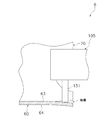
- FIG. 16 is a schematic front view of the manufacturing apparatus 100 for the impeller 8 (shown excluding the impeller support apparatus 101).
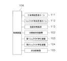
- FIG. 17 is a schematic diagram showing the insertion portions 113 and 114 of the main plate side ultrasonic horn 111 and the shroud side ultrasonic horn 112.
- FIG. 18 is a control block diagram of the manufacturing apparatus 100 for the impeller 8.
- FIG. 19 is a flowchart showing the manufacturing process of the impeller 8.
- FIG. 20 is a diagram for explaining the operation status of each part of the manufacturing apparatus 100 in the manufacturing process of the impeller 8.
- FIG. 21 is a diagram showing a state in which the insertion portions 113 and 114 of the main plate side ultrasonic horn 111 and the shroud side ultrasonic horn 112 are inserted at the welding locations.
- FIG. 22 is a diagram illustrating a state in which the outer peripheral edge portion of the main plate 60 is bent and deformed using the non-welding device 105.
- the manufacturing apparatus 100 of the impeller 8 faces a plurality of blades 70 arranged in a ring around the rotation axis O and two blade shaft end portions 71 and 72 that are both ends of the blade 70 on the rotation axis O direction side.
- the impeller 8 is manufactured by welding the main plate 60 and the shroud 80 that are arranged in the same manner.
- the manufacturing apparatus 100 mainly includes a welding device 101, an impeller support device 102, shroud pressing devices 103 and 104, a non-welding device 105, and a control device 106.
- the welding apparatus 101 mainly includes a main plate side ultrasonic horn 111 and a shroud side ultrasonic horn 112.
- the main plate-side ultrasonic horn 111 is ultrasonically applied to the blade 70 and the main plate 60 in order to weld the main plate-side blade shaft end portion 71 and the main plate 60, which is one of the two blade shaft end portions 71 and 72.
- An ultrasonic horn that imparts vibration.
- the shroud-side ultrasonic horn 112 is ultrasonic to the blade 70 and the shroud 80 in order to weld the shroud-side blade shaft end 72, which is the other of the two blade shaft ends 71, 72, and the shroud 80.
- An ultrasonic horn that imparts vibration.
- the main plate-side ultrasonic horn 111 has a main plate-side insertion portion 113 that is inserted through the main plate 60 until reaching a part of the main plate-side blade shaft end portion 71.
- the shroud-side ultrasonic horn 112 has a shroud-side insertion portion 114 that is inserted through the shroud 80 until reaching a part of the shroud-side blade shaft end portion 72.
- the main plate-side ultrasonic horn 111 has a plurality (three in this case) of main plate-side insertion portions 113 along the blade length direction of the main plate-side blade shaft end portion 71.
- the shroud side ultrasonic horn 112 has a plurality (three in this case) of shroud side insertion portions 114 along the blade length direction of the shroud side blade shaft end portion 72.
- the ultrasonic vibration is supplied to the main plate side ultrasonic horn 111 and the shroud side ultrasonic horn 112 by an ultrasonic oscillator 115 (shown only in FIG. 18).
- the main plate side ultrasonic horn 111 and the shroud side ultrasonic horn 112 are respectively supported by the base 107 so as to be movable by an air cylinder or the like.
- the main plate-side ultrasonic horn 111 and the shroud-side ultrasonic horn 112 are provided so as to perform welding between any one of the plurality of blades 70 and the main plate 60 and the shroud 80.
- the impeller support device 102 is a device that rotatably supports the main plate 60, the plurality of blades 70, and the shroud 80 around the rotation axis O, and mainly includes a rotary table 121 driven by a motor or the like.
- the turntable 121 has a disk shape whose diameter is smaller than that of the main plate 60.
- the rotary table 121 is formed with a table cutout 122 and a table through hole 123 for inserting the main plate side ultrasonic horn 111 into the main plate 60 from the side opposite to the blade side main plate surface 64.
- the same number of table cutouts 122 and table through holes 123 as the blades 70 (here, seven) are formed.
- the table notch 122 is disposed corresponding to the portion where the first main plate-side welded portion 8a is formed, and the table through hole 123 corresponds to the portion where the second main plate-side welded portion 8b is formed.
- the impeller support device 102 aligns any one of the plurality of blades 70 with respect to the main plate-side ultrasonic horn 111 and the shroud-side ultrasonic horn 112 by rotating the rotary table 121. It makes it possible.
- the shroud pressing devices 103 and 104 are devices that press the shroud 80 toward the main plate 60 when the main plate-side ultrasonic horn 111 welds the main plate-side blade shaft end portion 71 and the main plate 60 to each other. There are pressing pins 131 and 141 for pressing 80 predetermined portions.
- the shroud pressing devices 103 and 104 press the portion of the shroud 80 facing the rotation axis O direction of the portion where the main plate side insertion portion 113 is inserted into the main plate 60 and the main plate side blade shaft end portion 71 toward the main plate 60 side. It has become.
- the pressing pins 131 and 141 press the portion of the shroud 80 that opposes the portion of the shroud 80 where the main plate side insertion portion 113 is inserted into the main plate 60 and the main plate side blade shaft end portion 71 in the rotation axis O direction.
- the first shroud pressing device 103 having the first pressing pins 131 is a shroud flat plate portion 82 of the shroud 80 that is disposed facing the rotation axis O direction of the portion where the first main plate-side welded portion 8a is formed. Is to be pressed.
- the second shroud pressing device 104 having the second pressing pin 141 has the shroud flat surface 86a of the shroud 80 disposed facing the rotation axis O direction of the portion where the second main plate-side welded portion 8b is formed. It comes to press.
- the shroud pressing devices 103 and 104 are supported by the base 107 so as to be movable by an air cylinder or the like.
- the shroud pressing devices 103 and 104 perform welding between any one of the plurality of blades 70 and the main plate 60 and the shroud 80 by the main plate-side ultrasonic horn 111 and the shroud-side ultrasonic horn 112.
- the shroud 80 is provided so as to be pressed toward the main plate 60 side.
- the non-welding device 105 When welding the main plate side blade shaft end portion 71 and the main plate 60 with the main plate side ultrasonic horn 111, the non-welding device 105 includes a portion on the blade trailing edge side of the main plate side blade shaft end portion 71 and the main plate 60.
- the non-welding apparatus 105 mainly includes a bending pin 151 that bends the outer peripheral edge portion of the main plate 60 in a direction away from the blade trailing edge portion of the main plate-side blade shaft end portion 71.
- the non-welding device 105 is supported by the base 107 so as to be movable by an air cylinder or the like, like the main plate side ultrasonic horn 111, the shroud side ultrasonic horn 112, and the shroud pressing devices 103, 104. Yes.
- the non-welding device 105 is provided so as to bend and deform the main plate 60 when the main plate-side ultrasonic horn 111 performs welding between any one of the plurality of blades 70 and the main plate 60. It has been.
- the control device 106 is a device for performing the control operation of the various devices described above (shown only in FIG. 18), and is attached to the various devices or the base 107 or provided at a place away from the various devices or the base 107. It has been. The operation of the manufacturing apparatus 100 is performed by the control device 106.
- a resin-molded blade body 73, blade lid 74, main plate 60, and shroud 80 are prepared. Then, the blade lid 74 is attached to the blade body 73 by fitting, and the blade 70 is assembled. Then, the plurality of blades 70, the main plate 60, and the shroud 80 are temporarily assembled.
- the main plate projection 67 of the main plate 60 is inserted into the main plate-side blade hole 75 of the main plate-side blade shaft end portion 71 of the blade 70, thereby placing the blade 70 at a predetermined position of the main plate 60.
- the blade 70 is disposed at a predetermined position of the shroud 80 by fitting the blade step 77 of the shaft end portion 72 to the shroud step 83 of the shroud 60.
- the plurality of temporarily assembled blades 70, the main plate 60, and the shroud 80 are arranged on the rotary table 121 of the impeller support device 102 (step ST1).
- the first anti-blade side main plate concave portion 65a of the main plate 60 corresponds to the table cutout 122, and the second anti-rotation of the main plate 60 is performed.
- the blade side main plate recess 65 b is arranged on the rotary table 121 in a state corresponding to the table through hole 123.
- the two blade shaft end portions 71 and 72 of the plurality of blades 70 and the main plate 60 and the shroud 80 are welded to each other through the steps ST2 to ST9, whereby the impeller 8 of the centrifugal fan 4 is moved. Finalize.
- These steps ST2 to ST9 are performed by the control unit 106.
- welding between the main plate side blade shaft end portion 71 and the main plate 60 and between the shroud side blade shaft end portion 72 and the shroud 80 are performed by the plurality of blades 70. One by one is sequentially performed.
- step ST2 in order to weld the main plate side blade shaft end 71 of the blade 70 and the main plate 60, the shroud pressing devices 103 and 104 press the shroud 80 toward the main plate 60 side.
- the shroud flat plate portion 82 is pressed toward the main plate 60 by the pressing pin 131 of the first shroud pressing device 103.
- the shroud flat surface 86a of the shroud 80 is pressed toward the main plate 60 side by the pressing pin 141 of the second shroud pressing device 104.
- step ST ⁇ b> 3 ultrasonic vibration is supplied from the ultrasonic oscillator 115 to the main plate side ultrasonic horn 111, and ultrasonic waves are applied to the blade 70 and the main plate 60 by the main plate side insertion portion 113 of the main plate side ultrasonic horn 111. Apply vibration.
- ultrasonic vibration is applied to the blade 70 and the main plate 60 from the first anti-blade side main plate recess 65a, which is a portion of the shroud flat plate portion 82 facing the rotation axis O direction.
- the main plate side insertion portion 113 is inserted through the main plate 60 (here, the first anti-blade side main plate recess 65a) until reaching a part of the main plate side blade shaft end portion 71.
- the portion of the main plate side blade shaft end portion 71 near the blade trailing edge in the blade length direction and the first anti-blade side main plate recess 65a of the main plate 60 penetrate the main plate 60 and the main plate side blade shaft end portion 71 of the main plate side blade shaft end portion 71.
- the main plate-side blade shaft end 71 and the main plate 60 are melted so that the main plate-side welding hole 8d, which is a recess reaching a part, is formed.
- the 1st main board side welding part 8a which has such a main board side welding hole 8d is formed.
- a plurality of main plate side welding holes 8d are formed along the blade length direction of the main plate side blade shaft end portion 71 by a plurality of (here, three) main plate side insertion portions 113.
- step ST ⁇ b> 4 ultrasonic vibration is supplied from the ultrasonic oscillator 115 to the shroud ultrasonic horn 112, and ultrasonic waves are applied to the blade 70 and the shroud 80 by the shroud side insertion portion 114 of the shroud ultrasonic horn 112. Apply vibration.
- ultrasonic vibration is applied to the blade 70 and the shroud 80 from the shroud flat plate portion 82.
- the shroud side insertion portion 114 is inserted until it reaches a part of the shroud side blade shaft end portion 72 through the shroud 80 (here, the shroud flat plate portion 82).
- the portion near the center in the blade length direction of the shroud side blade shaft end portion 72 and the shroud flat plate portion 82 of the shroud 80 are recessed with penetrating the shroud 80 to a part of the shroud side blade shaft end portion 72.
- the shroud side blade shaft end 72 and the shroud 80 are melted so that a certain shroud side welding hole 8e is formed.
- the shroud side welding part 8c which has such a shroud side welding hole 8e is formed.
- a plurality of shroud-side welding holes 8 e are formed along the blade length direction of the shroud-side blade shaft end portion 72 by a plurality (here, three) of shroud-side insertion portions 114.
- step ST5 in parallel with the step ST4, the main plate-side ultrasonic horn 111 is moved from the position corresponding to the first anti-blade side main plate recess 65a of the main plate 60 (the position of the table cutout 122) to the main plate 60. It is moved to the position corresponding to the second counter blade side main plate recess 65b (the position of the table through hole 123). Note that this step is not necessary when the main plate-side ultrasonic horn 111 is provided corresponding to each of the two welding locations on the main plate 60 side.
- step ST ⁇ b> 6 ultrasonic vibration is supplied from the ultrasonic oscillator 115 to the main plate side ultrasonic horn 111, and ultrasonic waves are applied to the blade 70 and the main plate 60 by the main plate side insertion portion 113 of the main plate side ultrasonic horn 111. Apply vibration.
- ultrasonic vibration is applied to the blade 70 and the main plate 60 from the second anti-blade side main plate recess 65b, which is a portion of the shroud flat surface 86a that faces the rotation axis O direction.
- the main plate side insertion portion 113 is inserted until it reaches a part of the main plate side blade shaft end portion 71 through the main plate 60 (here, the second anti-blade side main plate recess 65b).
- the portion of the main plate side blade shaft end portion 71 near the blade trailing edge in the blade length direction and the second anti-blade side main plate concave portion 65b of the main plate 60 penetrate the main plate 60 and the main plate side blade shaft end portion 71 of the main plate side blade shaft end portion 71.
- the main plate-side blade shaft end 71 and the main plate 60 are melted so that the main plate-side welding hole 8d, which is a recess reaching a part, is formed.
- the 2nd main board side welding part 8b which has such a main board side welding hole 8d is formed.
- a plurality of main plate side welding holes 8d are formed along the blade length direction of the main plate side blade shaft end portion 71 by a plurality of (here, three) main plate side insertion portions 113.
- step ST7 the pressing of the shroud 80 by the shroud pressing devices 103 and 104 and the bending deformation of the main plate 60 by the non-welding device 105 are released.
- the pressing of the shroud 80 by the shroud pressing devices 103 and 104 and the bending deformation of the main plate 60 by the non-welding device 105 are collectively performed in step ST2, so this step is necessary.
- pressing the shroud 80 by the shroud pressing devices 103 and 104 and bending deformation of the main plate 60 by the non-welding device 105 are performed in the welding process of steps ST3, ST4 and ST6, it is released every time the welding process is performed. Therefore, this step is unnecessary.
- step ST8 it is determined whether or not the welding between all the blades 70 and the main plate 60 and the shroud 80 has been completed.
- the manufacturing process of the impeller 8 is finished. Thereby, the impeller 8 is completed.
- step ST9 the rotary table 121 of the impeller support device 102 is rotated to be adjacent in the circumferential direction. Move to a position corresponding to the blade 70. The steps ST2 to ST9 are repeated until the welding between all the blades 70 and the main plate 60 and the shroud 80 is completed.
- the impeller 8 of the centrifugal fan 4, the manufacturing method, and the manufacturing device 100 have the following features.
- ⁇ A> A plurality of blades 70 arranged in a ring around the rotation axis O, and a main plate 60 and a shroud 80 arranged opposite to the two blade shaft ends 71 and 72 that are both ends of the blade 70 on the direction of the rotation axis O.
- a mold for previously forming edges, through-holes, and protrusions necessary for welding In order to make it possible to manufacture the impeller 8 of the centrifugal fan 4 at a low cost, a mold for previously forming edges, through-holes, and protrusions necessary for welding. Further, it is necessary to reduce the molding process, reduce the area of the welded portion, and downsize the ultrasonic horn and the ultrasonic oscillator.
- the main plate-side weld portions 8a and 8b having the main plate-side weld holes 8d and 8e, which are recesses that penetrate the main plate 60 and reach a part of the main plate-side blade shaft end portion 71, are formed.
- a shroud-side weld portion 8c having a shroud-side weld hole 8e that is a recess that passes through the shroud 80 and reaches the shroud-side blade shaft end portion 72 is formed.
- the welded portions 8a, 8b, and 8c having such weld holes 8d and 8e have insertion portions 113 and 114 inserted through the main plate 60 and the shroud 80 until reaching a part of the blade shaft end portions 71 and 72, respectively. It can be obtained by ultrasonic welding using the ultrasonic horns 111 and 112 that are provided. That is, when welding the main plate side blade shaft end portion 71 and the main plate 60, ultrasonic vibration is applied to the blade 70 and the main plate 60 using the main plate side ultrasonic horn 111 having the main plate side insertion portion 113.
- the main plate side blade shaft end portion 71 and the main plate 60 are melted so as to form a main plate side welding hole 8d that is a recess that penetrates the main plate 60 and reaches a part of the main plate side blade shaft end portion 71.
- the main plate side welding portions 8a and 8b having the main plate side welding holes 8d are formed. Further, when welding the shroud side blade shaft end portion 72 and the shroud 80 to each other, ultrasonic vibration is applied to the blade 70 and the shroud 80 using the shroud side ultrasonic horn 112 having the shroud side insertion portion 114.
- the shroud side blade shaft end portion 72 and the shroud 80 are melted so as to form a shroud side welding hole 8e that is a recess that penetrates the shroud 80 and reaches a part of the shroud side blade shaft end portion 72.
- the shroud side welding part 8c which has the shroud side welding hole 8e is formed.
- welding part 8a, 8b, 8c which has such welding holes 8d and 8e the metal mold
- the area of the welded portion can be reduced. Further, if the area of the welded portion is reduced, the ultrasonic horn can be reduced in size, and the output of the ultrasonic oscillator can be reduced.
- the plurality of blades 70 arranged in a ring around the rotation axis and the two blade shaft end portions 71 and 72 which are both ends of the blade 70 on the rotation axis O direction side are arranged.
- the impeller 8 of the centrifugal fan 4 that is formed by welding the main plate 60 and the shroud 80 to each other can be manufactured at low cost.
- the main plate-side ultrasonic horn 111 has a plurality of main plate-side insertion portions 113 along the blade length direction of the main plate-side blade shaft end 71, and the shroud-side ultrasonic horn 112 is a shroud.
- a plurality of side insertion portions 114 are provided along the blade length direction of the shroud side blade shaft end portion 112. Therefore, a plurality of main plate side welding holes 8d are formed along the blade length direction of the main plate side blade shaft end portion 71, and the shroud side welding holes 8e are formed along the blade length direction of the shroud side blade shaft end portion 72. A plurality are formed.
- the main plate-side welding hole 8d is opened in the opposite blade-side main plate surface 64 of the main plate 60, and a built-up portion is formed around the opening by melting of the main plate 60 and the blade 70 during welding.
- the Such a built-up portion protrudes in the direction of the rotation axis O from the opposite blade side main plate surface 64 of the main plate 60, which may cause ventilation resistance during operation of the centrifugal fan 4 and may cause noise. is there.
- a convex anti-blade side main plate convex portion 65 corresponding to the main plate side blade shaft end portion 71 is formed on the anti-blade side main plate surface 64, and the anti-blade side main plate convex portion 65 is formed.
- the concave anti-blade side main plate recesses 65a and 65b are formed in the main plate side, and the main plate side welds 8a and 8b are formed by applying ultrasonic welding to the anti-blade side main plate recesses 65a and 65b.
- the build-up portions formed around the main plate side welding holes 8d of the main plate side welding portions 8a and 8b are disposed in the anti-blade side main plate recesses 65a and 65b, and although it protrudes in the direction of the rotation axis O from the blade side main plate recesses 65a and 65b, it can be suppressed to a protrusion below the anti-blade side main plate protrusion 65 around the anti-blade side main plate recesses 65a and 65b.
- the shroud 80 is a bell-shaped member that is curved so that its diameter decreases as it moves away from the blade 70 in the direction of the rotation axis O, and the shroud curved plate portion 81 and the shroud-side blade that form such a bell shape. It is not easy to weld the shaft end portion 72 to each other.
- a flat shroud flat plate portion 82 is formed in the shroud 80 corresponding to the shroud side blade shaft end portion 72, and the blade 70 and the shroud 80 are formed from the shroud flat plate portion 82.
- the shroud flat plate portion 82 is disposed so as to correspond to the vicinity of the center in the blade length direction of the shroud side blade shaft end portion 72, and the shroud flat plate portion 82 and the shroud side blade shaft end portion 72. Ultrasonic vibration is applied to the vicinity of the center in the blade length direction of the blade to weld the shroud side blade shaft end 72 and the shroud 80 to each other.
- the welding between the shroud side blade shaft end portion 72 and the shroud 80 is stronger than that in the case where the blade 70 is close to the blade leading edge portion or the blade trailing edge portion. Since it becomes possible, the area of the shroud flat plate portion 82, and consequently the area of the shroud side weld portion 8c formed by welding can be reduced.
- the main plate 60 is formed with the weir portion 66 along the blade trailing edge side portion of the main plate-side blade shaft end portion 71.
- the main plate 60 and the blade 70 are melted when the main plate-side blade shaft end portion 71 and the main plate 60 are welded. At this time, such a melted material is on the blade trailing edge side of the main plate-side blade shaft end portion 71. It is possible to suppress the outflow from between the portion and the main plate 60 by the weir portion 66.
- the main plate side ultrasonic horn 111 and the shroud side ultrasonic horn 112 are provided so as to perform welding between any one of the plurality of blades 70 and the main plate 60 and the shroud 80.
- the main plate 60, the plurality of blades 70, and the shroud 80 are arranged so that any one of the plurality of blades 70 can be aligned with the main plate side ultrasonic horn 111 and the shroud side ultrasonic horn 112.
- An impeller support device 102 is provided for rotatably supporting the rotation around the rotation axis O.
- an ultrasonic horn can be further reduced in size.
- the output of the ultrasonic oscillator can be further reduced.
- the shroud pressing devices 103 and 104 that press the shroud 80 toward the main plate side are used. Is provided.
- the shroud 80 can be pressed toward the main plate 60 side, and the main plate 60 side by the main plate side ultrasonic horn 111. It is possible to receive a pressing force from.
- the shroud pressing devices 103 and 104 are portions of the shroud 80 facing the rotation axis O direction of the portion where the main plate side insertion portion 113 is inserted into the main plate 60 and the main plate side blade shaft end portion 71. Is pressed against the main plate 60 side.
- the shroud 80 is a bell-shaped member that is curved so that the diameter decreases as it moves away from the blade 70 in the direction of the rotation axis O, it is not easy to appropriately press the shroud 80 toward the main plate 60. Absent.
- the shroud flat surface 86a made of a flat surface is formed on the anti-blade side shroud surface 85 of the shroud 80 so as to face the rotation axis O direction of the main plate side welded portion 8b.
- a portion of the shroud 80 which is more advantageous for pressing toward the main plate 60 side than the shroud curved plate portion 81, which is the shroud flat surface 86a, is provided.
- the ultrasonic vibration can be applied to the blade 70 and the main plate 60 from the portion of the main plate 60 facing the rotation axis O direction of the shroud flat surface 86a while pressing toward the 60 side.
- the shroud flat surface 86a faces the direction of the rotation axis O of the second main plate side welded portion 8b, the portion of the shroud 80 that requires the most pressing toward the main plate 60 side is appropriately pressed. Can do.
- the shroud flat plate portion 82 formed for welding the shroud side blade shaft end portion 72 and the shroud 80 to each other is used in the direction of the rotation axis O of the first main plate side weld portion 8a. It is arranged so as to oppose to. Therefore, when welding the main plate side blade shaft end portion 71 and the main plate 60, a portion of the shroud 80, which is more advantageous for pressing toward the main plate 60 than the shroud curved plate portion 81, which is the shroud flat plate portion 82, is provided.
- the ultrasonic vibration can be applied to the blade 70 and the main plate 60 from the portion of the main plate 60 facing the rotation axis O direction of the shroud flat plate portion 82 while pressing toward the 60 side.
- the shroud flat plate portion 82 faces the direction of the rotation axis O of the first main plate-side welded portion 8a, so that the portion of the shroud 80 that requires the most pressing toward the main plate 60 side is appropriately pressed. Can do.
- the shroud 80 can be appropriately pressed toward the main plate 60 side.
- the main plate side welded portions 8a and 8b are formed by welding the main plate side blade shaft end portion 71 and the main plate 60. At this time, such main plate side welded portions 8a, The portion on the blade trailing edge side than 8b may be weakly welded. And if it is weakly welded at the portion on the blade trailing edge side from the first main plate-side welded portion 8a, such a weakly welded portion may be detached during operation of the centrifugal fan 4, and noise may be generated. .
- a gap is secured between the main plate 60 and the portion on the blade trailing edge side of the main plate side blade shaft end portion 71 by the non-welded portion 8f, and the main plate 60 has a gap. Also, ultrasonic vibration is applied to the blade 70 and the main plate 60 from the blade leading edge side portion.
- the main plate 60 is bent and deformed by using the non-welding device 105 to thereby deform the main plate side blade shaft end.
- the ultrasonic vibration is applied to the blade 70 and the main plate 60 from a portion of the main plate 60 closer to the blade leading edge than the gap in a state where a gap is secured between the portion on the blade trailing edge side of the portion 71 and the main plate 60. I have to.
- the non-welding portion 8f is provided on the impeller 8 side and the non-welding device 105 is also provided on the manufacturing apparatus 100 side. However, only one of them may be provided.
- a plurality of blades arranged annularly around a rotation axis, and a main plate and a shroud arranged opposite to two blade shaft ends that are both ends on the rotation axis direction side of the blade Can be widely applied to the impeller of a centrifugal fan, its manufacturing method and manufacturing apparatus.
- JP 2008-111393 A Japanese Patent Laying-Open No. 2015-86827
Landscapes
- Engineering & Computer Science (AREA)
- Mechanical Engineering (AREA)
- General Engineering & Computer Science (AREA)
- Structures Of Non-Positive Displacement Pumps (AREA)
Abstract
Description
特許文献2においては、超音波溶着によって遠心ファンの羽根車を製造するにあたり、主板側溶着部やシュラウド側溶着部をなす部分にエッジを形成しておき、超音波振動を付与してエッジを溶融させるようにしている。また、特許文献1においては、超音波溶着によって遠心ファンの羽根車を製造するにあたり、主板側溶着部やシュラウド側溶着部をなす部分に貫通孔及び貫通孔を貫通する突起を設けておき、超音波振動を付与して突起先端を溶融変形させるようにしている。
図1に本発明の一実施形態にかかる羽根車8を備えた遠心ファン4が採用された空気調和装置1の外観斜視図(天井は省略)を示す。空気調和装置1は、ここでは、天井設置型の空気調和装置であり、主として、内部に各種構成機器を収納するケーシング2と、ケーシング2の下側に配置された化粧パネル3と、を有している。
次に、羽根車8の構成について、図3~図13を用いて説明する。ここで、図3は、羽根車8の外観斜視図である。図4は、図3のA矢視図(シュラウド80の一部を除いて図示)である。図5は、図3のB矢視図(主板60の一部を除いて図示)である。図6は、図4のC部を拡大した図である。図7は、図5のD部を拡大した図である。図8は、図6及び図7のI-I断面を示す図である。図9は、図7のII-II断面及びIII-III断面を示す図である。図10は、主板60の一部を回転軸線O方向ブレード70側から見た図である。図11は、図7のIV-IV断面及びV-V断面を示す図である。図12は、図7のE部を正圧面側から見た拡大断面図である。図13は、図6のVI-VI断面を示す図である。
次に、羽根車8の製造方法及び製造装置について、図3~図22を用いて説明する。ここで、図14は、羽根車8の製造装置100の概略平面図である、図15は、羽根車8の製造装置100の概略側面図である。図16は、羽根車8の製造装置100の概略正面図(羽根車支持装置101を除いて図示)である。図17は、主板側超音波ホーン111及びシュラウド側超音波ホーン112の挿入部113、114を示す概略図である。図18は、羽根車8の製造装置100の制御ブロック図である。図19は、羽根車8の製造工程を示すフローチャートである。図20は、羽根車8の製造工程における製造装置100の各部の動作状況を説明する図である。図21は、主板側超音波ホーン111及びシュラウド側超音波ホーン112の挿入部113、114を溶着箇所に挿入した状態を示す図である。図22は、非溶着装置105を用いて主板60の外周縁部を撓み変形させた状態を示す図である。
羽根車8の製造装置100は、回転軸線O周りに環状に配置される複数のブレード70と、ブレード70の回転軸線O方向側の両端部である2つのブレード軸端部71、72に対向して配置される主板60及びシュラウド80と、の相互間を溶着させることによって、羽根車8を製造する装置である。製造装置100は、主として、溶着装置101と、羽根車支持装置102と、シュラウド押圧装置103、104と、非溶着装置105と、制御装置106と、を有している。
まず、樹脂成形されたブレード本体73、ブレード蓋体74、主板60及びシュラウド80を準備する。そして、ブレード蓋体74をブレード本体73に嵌め込みにより装着してブレード70を組み立てる。そして、複数のブレード70、主板60及びシュラウド80の仮組みを行う。ここでは、ブレード70の主板側ブレード軸端部71の主板側ブレード孔75に主板60の主板突起67を挿入することによって、ブレード70を主板60の所定位置に配置し、ブレード70のシュラウド側ブレード軸端部72のブレード段差部77をシュラウド60のシュラウド段差部83に嵌合することによって、ブレード70をシュラウド80の所定位置に配置するのである。
遠心ファン4の羽根車8、その製造方法及び製造装置100には、以下のような特徴がある。
回転軸線O周りに環状に配置される複数のブレード70と、ブレード70の回転軸線O方向側の両端部である2つのブレード軸端部71、72に対向して配置される主板60及びシュラウド80と、の相互間を溶着させてなる、遠心ファン4の羽根車8を安価に製造できるようにするためには、溶着に必要なエッジや貫通孔、突起を予め形成しておくための金型や成形加工を減らし、溶着部の面積を小さくし、超音波ホーンや超音波発振器を小型化する必要がある。
ここでは、上記のように、主板側超音波ホーン111が、主板側挿入部113を主板側ブレード軸端部71の翼長方向に沿って複数個有し、シュラウド側超音波ホーン112が、シュラウド側挿入部114をシュラウド側ブレード軸端部112の翼長方向に沿って複数個有するものとしている。このため、主板側溶着穴8dが、主板側ブレード軸端部71の翼長方向に沿って複数個形成され、シュラウド側溶着穴8eが、シュラウド側ブレード軸端部72の翼長方向に沿って複数個形成される。
ここでは、主板側溶着穴8dが、主板60の反ブレード側主板面64に開口しているところ、その開口の周囲には、溶着時の主板60やブレード70の溶融によって肉盛り部分が形成される。このような肉盛り部分は、主板60の反ブレード側主板面64よりも回転軸線O方向に突出することになるため、遠心ファン4の運転時の通風抵抗になり、騒音の原因になるおそれがある。
ここでは、シュラウド80が、ブレード70側から回転軸線O方向に遠ざかるにつれて径が小さくなるように湾曲したベル形状の部材であるところ、このようなベル形状をなすシュラウド曲板部81とシュラウド側ブレード軸端部72との相互間を溶着することは容易ではない。
ここでは、上記のように、シュラウド平板部82が、シュラウド側ブレード軸端部72の翼長方向の中央付近に対応するように配置されており、シュラウド平板部82及びシュラウド側ブレード軸端部72の翼長方向の中央付近に対して超音波振動を付与してシュラウド側ブレード軸端部72とシュラウド80との相互間の溶着を行うようにしている。
ここでは、上記のように、主板60には、主板側ブレード軸端部71の翼後縁側の部分に沿うように堰部66が形成されている。
ここでは、上記のように、主板側超音波ホーン111及びシュラウド側超音波ホーン112が、複数のブレード70のいずれか1つと主板60及びシュラウド80との相互間の溶着を行うように設けられている。そして、主板側超音波ホーン111及びシュラウド側超音波ホーン112に対して、複数のブレード70のいずれか1つを位置合わせすることが可能になるように、主板60、複数のブレード70及びシュラウド80を回転軸線O周りに回転自在に支持する羽根車支持装置102が設けられている。そして、これらの構成によって、主板側ブレード軸端部71と主板60との相互間、及び、シュラウド側ブレード軸端部72とシュラウド80との相互間の溶着を、複数のブレード70の1つずつに対して順次行うようにしている。
主板側ブレード軸端部71と主板60との相互間を溶着させるにあたり、主板側からブレード70及び主板60に対して超音波振動を付与する際には、主板側超音波ホーン111によって主板60がシュラウド側に向かって押圧されることになる。
ここでは、上記のように、シュラウド押圧装置103、104が、シュラウド80のうち主板側挿入部113が主板60及び主板側ブレード軸端部71に挿入される部分の回転軸線O方向に対向する部分を主板60側に押圧するようにしている。
上記のように、主板側ブレード軸端部71と主板60との相互間が溶着されることで主板側溶着部8a、8bが形成されるが、このとき、このような主板側溶着部8a、8bよりも翼後縁側の部分も、弱く溶着されるおそれがある。そして、第1主板側溶着部8aよりも翼後縁側の部分で弱く溶着されると、遠心ファン4の運転時にこのような弱く溶着された部分が外れてしまい、異音を発生させるおそれがある。
8 羽根車
8a、8b 主板側溶着部
8c シュラウド側溶着部
8d 主板側溶着穴
8e シュラウド側溶着穴
8f 非溶着部
60 主板
63 ブレード側主板面
64 反ブレード側主板面
65 反ブレード側主板凸部
65a、65b 反ブレード側主板凹部
66 堰部
70 ブレード
71 主板側ブレード軸端部
72 シュラウド側ブレード軸端部
80 シュラウド
82 シュラウド平板部
84 ブレード側シュラウド面
85 反ブレード側シュラウド面
86a シュラウド平坦面
100 製造装置
102 羽根車支持装置
103 第1シュラウド押圧装置
104 第2シュラウド押圧装置
105 非溶着装置
111 主板側超音波ホーン
112 シュラウド側超音波ホーン
113 主板側挿入部
114 シュラウド側挿入部
Claims (19)
- 回転軸線周りに環状に配置されており、前記回転軸線方向側の両端部である2つのブレード軸端部(71、72)を有する複数のブレード(70)と、
前記2つのブレード軸端部の一方である主板側ブレード軸端部に対向して配置されている主板(60)と、
前記2つのブレード軸端部の他方であるシュラウド側ブレード軸端部に対向して配置されているシュラウド(80)と、
を備えており、
前記主板側ブレード軸端部と前記主板との相互間に主板側溶着部(8a、8b)を有しており、
前記シュラウド側ブレード軸端部と前記シュラウドとの相互間にシュラウド側溶着部(8c)を有している、
遠心ファン(4)の羽根車において、
前記主板側溶着部には、前記主板を貫通して前記主板側ブレード軸端部の一部まで達する凹みである主板側溶着穴(8d)が形成されている、
前記シュラウド側溶着部には、前記シュラウドを貫通して前記シュラウド側ブレード軸端部まで達する凹みであるシュラウド側溶着穴(8e)が形成されている、
遠心ファンの羽根車(8)。 - 前記主板は、前記主板側ブレード軸端部に対向する面であるブレード側主板面(63)と、前記ブレード側主板面の前記回転軸線方向の反対側の面である反ブレード側主板面(64)と、を有しており、
前記反ブレード側主板面には、前記主板側ブレード軸端部に対応して凸状の反ブレード側主板凸部(65)が形成されており、
前記反ブレード側主板凸部には、凹状の反ブレード側主板凹部(65a、65b)が形成されており、
前記主板側溶着部は、前記反ブレード側主板凹部に配置されている、
請求項1に記載の遠心ファンの羽根車。 - 前記シュラウドには、前記シュラウド側ブレード軸端部に対応して平板状のシュラウド平板部(82)が形成されており、
前記シュラウド側溶着部は、前記シュラウド平板部に配置されている、
請求項1又は2に記載の遠心ファンの羽根車。 - 前記シュラウド平板部は、前記主板側溶着部の前記回転軸線方向に対向して配置されている、
請求項3に記載の遠心ファンの羽根車。 - 前記シュラウドは、前記シュラウド側ブレード軸端部に対向する面であるブレード側シュラウド面(84)と、前記ブレード側シュラウド面の前記回転軸線方向の反対側の面である反ブレード側シュラウド面(85)と、を有しており、
前記反ブレード側シュラウド面には、前記主板側溶着部の前記回転軸線方向に対向して平坦面からなるシュラウド平坦面(86a)が形成されている、
請求項1~4のいずれか1項に記載の遠心ファンの羽根車。 - 前記主板側ブレード軸端部又は前記主板には、前記主板側溶着部よりも前記ブレードの翼後縁側の部分に、前記主板側ブレード軸端部と前記主板との間に隙間を確保するための非溶着部(8f)が形成されている、
請求項1~5のいずれか1項に記載の遠心ファンの羽根車。 - 前記主板には、前記主板側ブレード軸端部の翼後縁側の部分に沿うように堰部(66)が形成されている、
請求項1~6のいずれか1項に記載の遠心ファンの羽根車。 - 回転軸線周りに環状に配置される複数のブレード(70)と、前記ブレードの前記回転軸線方向側の両端部である2つのブレード軸端部(71、72)に対向して配置される主板(60)及びシュラウド(80)と、の相互間を溶着させてなる、遠心ファン(4)の羽根車(8)の製造方法において、
前記2つのブレード軸端部の一方である主板側ブレード軸端部と前記主板との相互間、及び、前記2つのブレード軸端部の他方であるシュラウド側ブレード軸端部と前記シュラウドとの相互間、を溶着させるにあたり、
前記ブレード及び前記主板に対して超音波振動を付与して、前記主板を貫通して前記主板側ブレード軸端部の一部まで達する凹みである主板側溶着穴(8d)が形成されるように前記主板側ブレード軸端部及び前記主板を溶融させ、
前記ブレード及び前記シュラウドに対して超音波振動を付与して、前記シュラウドを貫通して前記シュラウド側ブレード軸端部の一部まで達する凹みであるシュラウド側溶着穴(8e)が形成されるように前記シュラウド側ブレード軸端部及び前記シュラウドを溶融させる、
遠心ファンの羽根車の製造方法。 - 前記主板側ブレード軸端部と前記主板との相互間、及び、前記シュラウド側ブレード軸端部と前記シュラウドとの相互間の溶着を、前記複数のブレードの1つずつに対して順次行う、
請求項8に記載の遠心ファンの羽根車の製造方法。 - 前記主板は、前記主板側ブレード軸端部に対向する面であるブレード側主板面(63)と、前記ブレード側主板面の前記回転軸線方向の反対側の面である反ブレード側主板面(64)と、を有しており、
前記反ブレード側主板面に前記主板側ブレード軸端部に対応して凸状の反ブレード側主板凸部(64a)を形成し、
前記反ブレード側主板凸部に凹状の反ブレード側主板凹部(64b)を形成し、
前記主板側ブレード軸端部と前記主板との相互間を溶着させるにあたり、前記反ブレード側主板凹部から前記ブレード及び前記主板に対して超音波振動を付与する、
請求項8又は9に記載の遠心ファンの羽根車の製造方法。 - 前記シュラウドに前記シュラウド側ブレード軸端部に対応して平板状のシュラウド平板部(82)を形成し、
前記シュラウド側ブレード軸端部と前記シュラウドとの相互間を溶着させるにあたり、前記シュラウド平板部から前記ブレード及び前記シュラウドに対して超音波振動を付与する、
請求項8~10のいずれか1項に記載の遠心ファンの羽根車の製造方法。 - 前記主板側ブレード軸端部と前記主板との相互間を溶着させるにあたり、前記シュラウド平板部を前記主板側に押圧しながら、前記主板のうち前記シュラウド平板部の前記回転軸線方向に対向する部分から前記ブレード及び前記主板に対して超音波振動を付与する、
請求項11に記載の遠心ファンの羽根車の製造方法。 - 前記シュラウドは、前記シュラウド側ブレード軸端部に対向する面であるブレード側シュラウド面(84)と、前記ブレード側シュラウド面の前記回転軸線方向の反対側の面である反ブレード側シュラウド面(85)と、を有しており、
前記反ブレード側シュラウド面に平坦面からなるシュラウド平坦面(86a)を形成し、
前記主板側ブレード軸端部と前記主板との相互間を溶着させるにあたり、前記シュラウド平坦面を前記主板側に押圧しながら、前記主板のうち前記シュラウド平坦面の前記回転軸線方向に対向する部分から前記ブレード及び前記主板に対して超音波振動を付与する、
請求項8~12のいずれか1項に記載の遠心ファンの羽根車の製造方法。 - 前記主板側ブレード軸端部と前記主板との相互間を溶着させるにあたり、前記主板側ブレード軸端部の翼後縁側の部分と前記主板との間に隙間を確保した状態で、前記主板のうち前記隙間よりも翼前縁側の部分から前記ブレード及び前記主板に対して超音波振動を付与する、
請求項8~13のいずれか1項に記載の遠心ファンの羽根車の製造方法。 - 回転軸線周りに環状に配置される複数のブレード(70)と、前記ブレードの前記回転軸線方向側の両端部である2つのブレード軸端部(71、72)に対向して配置される主板(60)及びシュラウド(80)と、の相互間を溶着させてなる、遠心ファン(4)の羽根車(8)の製造装置において、
前記2つのブレード軸端部の一方である主板側ブレード軸端部と前記主板との相互間を溶着させるために前記ブレード及び前記主板に対して超音波振動を付与する主板側超音波ホーン(111)と、
前記2つのブレード軸端部の他方であるシュラウド側ブレード軸端部と前記シュラウドとの相互間を溶着させるために前記ブレード及び前記シュラウドに対して超音波振動を付与するシュラウド側超音波ホーン(112)と、
を備えており、
前記主板側超音波ホーンは、前記主板を貫通して前記主板側ブレード軸端部の一部に達するまで挿入される主板側挿入部(113)を有しており、
前記シュラウド側超音波ホーンは、前記シュラウドを貫通して前記シュラウド側ブレード軸端部の一部に達するまで挿入されるシュラウド側挿入部(114)を有している、
遠心ファンの羽根車の製造装置(100)。 - 前記主板側超音波ホーン及び前記シュラウド側超音波ホーンは、前記複数のブレードのいずれか1つと前記主板及び前記シュラウドとの相互間の溶着を行うように設けられており、
前記主板側超音波ホーン及び前記シュラウド側超音波ホーンに対して、前記複数のブレードのいずれか1つを位置合わせすることが可能になるように、前記主板、前記複数のブレード及び前記シュラウドを前記回転軸線周りに回転自在に支持する羽根車支持装置(102)をさらに備えている、
請求項15に記載の遠心ファンの羽根車の製造装置。 - 前記主板側超音波ホーンによって前記主板側ブレード軸端部と前記主板との相互間を溶着させるにあたり、前記シュラウドを前記主板側に押圧するシュラウド押圧装置(103、104)をさらに備えている、
請求項15又は16に記載の遠心ファンの羽根車の製造装置。 - 前記シュラウド押圧装置は、前記シュラウドのうち前記主板側挿入部が前記主板及び前記主板側ブレード軸端部に挿入される部分の前記回転軸線方向に対向する部分を前記主板側に押圧する、
請求項17に記載の遠心ファンの羽根車の製造装置。 - 前記主板側超音波ホーンによって前記主板側ブレード軸端部と前記主板との相互間を溶着させるにあたり、前記主板側ブレード軸端部の翼後縁側の部分と前記主板のうち前記主板側挿入部が前記主板及び前記主板側ブレード軸端部に挿入される部分よりも前記ブレードの翼後縁側の部分との間に隙間が確保されるように、前記主板を撓み変形させる非溶着装置(105)をさらに備えている、
請求項15~18のいずれか1項に記載の遠心ファンの羽根車の製造装置。
Priority Applications (7)
| Application Number | Priority Date | Filing Date | Title |
|---|---|---|---|
| AU2016381760A AU2016381760B2 (en) | 2015-12-28 | 2016-08-10 | Impeller of centrifugal fan and method and apparatus for manufacturing the same |
| CN201680076356.0A CN108431427B (zh) | 2015-12-28 | 2016-08-10 | 离心风扇的叶轮及其制造方法和制造装置 |
| EP19214746.0A EP3650705B1 (en) | 2015-12-28 | 2016-08-10 | Impeller of centrifugal fan |
| BR112018011912-1A BR112018011912B1 (pt) | 2015-12-28 | 2016-08-10 | Método e aparelho para fabricar um impulsor de um ventilador centrifugo |
| EP16881470.5A EP3399195B1 (en) | 2015-12-28 | 2016-08-10 | Method and apparatus for manufacturing an impeller of a centrifugal fan |
| ES16881470T ES2792034T3 (es) | 2015-12-28 | 2016-08-10 | Procedimiento y aparato de fabricación de un impulsor de un ventilador centrífugo |
| US16/065,989 US10697474B2 (en) | 2015-12-28 | 2016-08-10 | Impeller of centrifugal fan and method and apparatus for manufacturing the same |
Applications Claiming Priority (4)
| Application Number | Priority Date | Filing Date | Title |
|---|---|---|---|
| JP2015257012A JP6056953B1 (ja) | 2015-12-28 | 2015-12-28 | 遠心ファンの羽根車の製造装置 |
| JP2015-257011 | 2015-12-28 | ||
| JP2015257011A JP6056952B1 (ja) | 2015-12-28 | 2015-12-28 | 遠心ファンの羽根車及びその製造方法 |
| JP2015-257012 | 2015-12-28 |
Publications (1)
| Publication Number | Publication Date |
|---|---|
| WO2017115490A1 true WO2017115490A1 (ja) | 2017-07-06 |
Family
ID=59227380
Family Applications (1)
| Application Number | Title | Priority Date | Filing Date |
|---|---|---|---|
| PCT/JP2016/073637 WO2017115490A1 (ja) | 2015-12-28 | 2016-08-10 | 遠心ファンの羽根車、その製造方法及び製造装置 |
Country Status (7)
| Country | Link |
|---|---|
| US (1) | US10697474B2 (ja) |
| EP (2) | EP3650705B1 (ja) |
| CN (1) | CN108431427B (ja) |
| AU (1) | AU2016381760B2 (ja) |
| BR (1) | BR112018011912B1 (ja) |
| ES (2) | ES2880504T3 (ja) |
| WO (1) | WO2017115490A1 (ja) |
Cited By (1)
| Publication number | Priority date | Publication date | Assignee | Title |
|---|---|---|---|---|
| EP3660405A4 (en) * | 2017-07-26 | 2020-11-11 | Mitsubishi Electric Corporation | AIR CONDITIONER |
Families Citing this family (15)
| Publication number | Priority date | Publication date | Assignee | Title |
|---|---|---|---|---|
| US20120195749A1 (en) | 2004-03-15 | 2012-08-02 | Airius Ip Holdings, Llc | Columnar air moving devices, systems and methods |
| USD698916S1 (en) | 2012-05-15 | 2014-02-04 | Airius Ip Holdings, Llc | Air moving device |
| US9702576B2 (en) | 2013-12-19 | 2017-07-11 | Airius Ip Holdings, Llc | Columnar air moving devices, systems and methods |
| US10024531B2 (en) | 2013-12-19 | 2018-07-17 | Airius Ip Holdings, Llc | Columnar air moving devices, systems and methods |
| WO2015187856A1 (en) | 2014-06-06 | 2015-12-10 | Airius Ip Holdings, Llc | Columnar air moving devices, systems and methods |
| JP6281714B2 (ja) * | 2016-01-18 | 2018-02-21 | ダイキン工業株式会社 | 遠心ファン及び遠心ファンを備えた空気調和機 |
| JP6314998B2 (ja) * | 2016-01-18 | 2018-04-25 | ダイキン工業株式会社 | 遠心ファンの羽根車 |
| US10487852B2 (en) * | 2016-06-24 | 2019-11-26 | Airius Ip Holdings, Llc | Air moving device |
| USD949315S1 (en) * | 2016-06-24 | 2022-04-19 | Ebm-Papst Mulfingen Gmbh & Co. Kg | Vane damper with trailing edge |
| USD886275S1 (en) | 2017-01-26 | 2020-06-02 | Airius Ip Holdings, Llc | Air moving device |
| USD885550S1 (en) | 2017-07-31 | 2020-05-26 | Airius Ip Holdings, Llc | Air moving device |
| US10975879B2 (en) | 2018-07-18 | 2021-04-13 | The Charles Machine Works, Inc. | Centrifugal fan |
| USD887541S1 (en) | 2019-03-21 | 2020-06-16 | Airius Ip Holdings, Llc | Air moving device |
| AU2020257205A1 (en) | 2019-04-17 | 2021-11-04 | Airius Ip Holdings, Llc | Air moving device with bypass intake |
| SE1950948A1 (en) | 2019-08-20 | 2021-02-21 | Swegon Operations Ab | Fan for Air Handling Unit (AHU) |
Citations (7)
| Publication number | Priority date | Publication date | Assignee | Title |
|---|---|---|---|---|
| JPH10156555A (ja) * | 1996-11-20 | 1998-06-16 | Takashimaya Nippatsu Kogyo Kk | 超音波溶接機用の超音波ホーンおよびこれを用いたブラケット部品の取付方法 |
| JP2008111393A (ja) * | 2006-10-31 | 2008-05-15 | Nippon Kobunshi Kk | 遠心ファン及びその製造方法 |
| WO2009128299A1 (ja) * | 2008-04-18 | 2009-10-22 | 三菱電機株式会社 | ターボファンおよび空気調和機 |
| JP2010069492A (ja) * | 2008-09-16 | 2010-04-02 | Seidensha Electronics Co Ltd | 超音波加工用作業ヘッド、これを備えた超音波加工装置及び超音波加工システム |
| JP2010510911A (ja) * | 2006-11-27 | 2010-04-08 | マース インコーポレーテッド | 回転超音波シール |
| JP2014172083A (ja) * | 2013-03-12 | 2014-09-22 | Seidensha Electronics Co Ltd | ブースタホーン及びブースタホーンを用いた超音波溶着装置 |
| JP2015086827A (ja) * | 2013-11-01 | 2015-05-07 | 日清紡メカトロニクス株式会社 | ターボファン |
Family Cites Families (18)
| Publication number | Priority date | Publication date | Assignee | Title |
|---|---|---|---|---|
| US3563822A (en) | 1968-07-03 | 1971-02-16 | Branson Instr | Method for welding thermoplastic parts by sonic energy |
| JPH07103190A (ja) * | 1993-10-06 | 1995-04-18 | Takao Kobayashi | 軽量・低騒音型のターボファン用羽根車の構造。 |
| US6156090A (en) * | 1997-10-03 | 2000-12-05 | Hitachi, Ltd. | Air cleaner having vanes with a winglike cross-section between a shroud and baseplate for rotation within a housing |
| DE19751729C2 (de) * | 1997-11-21 | 2002-11-28 | Hermann Stahl Gmbh | Lüfterrad |
| JP4857631B2 (ja) * | 2005-07-15 | 2012-01-18 | 日本電産株式会社 | ファンモータ |
| JP3953085B1 (ja) * | 2006-03-08 | 2007-08-01 | ダイキン工業株式会社 | 遠心送風機用羽根車のブレード、ブレード支持回転体、遠心送風機用羽根車、及び遠心送風機用羽根車の製造方法 |
| JP2010180721A (ja) * | 2009-02-03 | 2010-08-19 | Mitsubishi Heavy Ind Ltd | インペラの製造方法および圧縮機 |
| CN102135110B (zh) * | 2010-01-27 | 2014-12-31 | 德昌电机(深圳)有限公司 | 离心式叶轮 |
| JP5988776B2 (ja) * | 2012-08-29 | 2016-09-07 | 三菱電機株式会社 | 遠心送風機及びこの遠心送風機を備えた空気調和機 |
| KR101645178B1 (ko) | 2013-05-10 | 2016-08-03 | 엘지전자 주식회사 | 원심팬 및 원심팬의 제조방법 |
| JP6341637B2 (ja) * | 2013-06-14 | 2018-06-13 | 三菱電機株式会社 | 遠心送風機の製造方法 |
| PL2846046T3 (pl) * | 2013-09-10 | 2018-04-30 | Punker Gmbh | Wirnik wentylatora |
| JP5984767B2 (ja) * | 2013-09-12 | 2016-09-06 | 三菱電機株式会社 | 遠心送風機及び空気調和機 |
| CN104690412A (zh) * | 2013-12-06 | 2015-06-10 | 浙江金海环境技术股份有限公司 | 风扇用超声波焊接设备以及其使用方法和应用 |
| FI127306B (en) * | 2014-06-26 | 2018-03-15 | Flaekt Woods Ab | IMPELLER |
| WO2016001368A1 (en) * | 2014-07-04 | 2016-01-07 | Nuovo Pignone Srl | Manufacturing of a turbomachine impeller by assembling a plurality of tubular components |
| CN104613006A (zh) * | 2014-12-10 | 2015-05-13 | 张凤荣 | 一种翼型材组合式透平离心式叶轮 |
| KR102289384B1 (ko) * | 2014-12-18 | 2021-08-13 | 삼성전자주식회사 | 원심팬 어셈블리 |
-
2016
- 2016-08-10 EP EP19214746.0A patent/EP3650705B1/en active Active
- 2016-08-10 EP EP16881470.5A patent/EP3399195B1/en active Active
- 2016-08-10 ES ES19214746T patent/ES2880504T3/es active Active
- 2016-08-10 WO PCT/JP2016/073637 patent/WO2017115490A1/ja active Application Filing
- 2016-08-10 CN CN201680076356.0A patent/CN108431427B/zh active Active
- 2016-08-10 ES ES16881470T patent/ES2792034T3/es active Active
- 2016-08-10 US US16/065,989 patent/US10697474B2/en active Active
- 2016-08-10 AU AU2016381760A patent/AU2016381760B2/en active Active
- 2016-08-10 BR BR112018011912-1A patent/BR112018011912B1/pt active IP Right Grant
Patent Citations (7)
| Publication number | Priority date | Publication date | Assignee | Title |
|---|---|---|---|---|
| JPH10156555A (ja) * | 1996-11-20 | 1998-06-16 | Takashimaya Nippatsu Kogyo Kk | 超音波溶接機用の超音波ホーンおよびこれを用いたブラケット部品の取付方法 |
| JP2008111393A (ja) * | 2006-10-31 | 2008-05-15 | Nippon Kobunshi Kk | 遠心ファン及びその製造方法 |
| JP2010510911A (ja) * | 2006-11-27 | 2010-04-08 | マース インコーポレーテッド | 回転超音波シール |
| WO2009128299A1 (ja) * | 2008-04-18 | 2009-10-22 | 三菱電機株式会社 | ターボファンおよび空気調和機 |
| JP2010069492A (ja) * | 2008-09-16 | 2010-04-02 | Seidensha Electronics Co Ltd | 超音波加工用作業ヘッド、これを備えた超音波加工装置及び超音波加工システム |
| JP2014172083A (ja) * | 2013-03-12 | 2014-09-22 | Seidensha Electronics Co Ltd | ブースタホーン及びブースタホーンを用いた超音波溶着装置 |
| JP2015086827A (ja) * | 2013-11-01 | 2015-05-07 | 日清紡メカトロニクス株式会社 | ターボファン |
Non-Patent Citations (1)
| Title |
|---|
| See also references of EP3399195A4 * |
Cited By (1)
| Publication number | Priority date | Publication date | Assignee | Title |
|---|---|---|---|---|
| EP3660405A4 (en) * | 2017-07-26 | 2020-11-11 | Mitsubishi Electric Corporation | AIR CONDITIONER |
Also Published As
| Publication number | Publication date |
|---|---|
| US20190010961A1 (en) | 2019-01-10 |
| CN108431427A (zh) | 2018-08-21 |
| ES2880504T3 (es) | 2021-11-24 |
| ES2792034T3 (es) | 2020-11-06 |
| EP3650705A8 (en) | 2020-10-07 |
| BR112018011912B1 (pt) | 2022-11-29 |
| BR112018011912A2 (ja) | 2018-11-27 |
| US10697474B2 (en) | 2020-06-30 |
| EP3399195A4 (en) | 2018-12-19 |
| EP3399195A1 (en) | 2018-11-07 |
| EP3650705B1 (en) | 2021-04-14 |
| CN108431427B (zh) | 2019-07-26 |
| EP3399195B1 (en) | 2020-02-19 |
| AU2016381760B2 (en) | 2018-08-30 |
| AU2016381760A1 (en) | 2018-08-09 |
| EP3650705A1 (en) | 2020-05-13 |
Similar Documents
| Publication | Publication Date | Title |
|---|---|---|
| WO2017115490A1 (ja) | 遠心ファンの羽根車、その製造方法及び製造装置 | |
| KR102212652B1 (ko) | 원심팬 | |
| JP6341637B2 (ja) | 遠心送風機の製造方法 | |
| JP4294046B2 (ja) | 遠心ファン及びその製造方法 | |
| JP4699531B2 (ja) | インペラの製造方法およびインペラ | |
| JP6056952B1 (ja) | 遠心ファンの羽根車及びその製造方法 | |
| JPH11101198A (ja) | 遠心送風機及びその製造方法並びに該遠心送風機を備えた空気調和機 | |
| WO2012002107A1 (ja) | インペラとその製造方法 | |
| JP5984767B2 (ja) | 遠心送風機及び空気調和機 | |
| JP6056953B1 (ja) | 遠心ファンの羽根車の製造装置 | |
| CN108571465B (zh) | 涡轮风扇 | |
| JP2010236495A (ja) | インペラの高精度製造法 | |
| JP4821084B2 (ja) | ターボファン及びターボファンの製造方法 | |
| WO2017126444A1 (ja) | 遠心ファンの羽根車 | |
| JP2020012461A (ja) | 羽根車、及び軸流ファン | |
| JP2016084743A (ja) | ターボファン及びターボファンの製造方法 | |
| JP6075342B2 (ja) | 中空部品の製造方法 | |
| EP2835539B1 (en) | Method for producing centrifugal fan | |
| JP2010229953A (ja) | 樹脂インペラの製造法 | |
| WO2000073661A1 (en) | Turbo fan | |
| KR0185156B1 (ko) | 와류블로워의 임펠러 및 그 제조방법 | |
| JPH03253796A (ja) | 渦流ブロワの羽根車及びその製造方法 | |
| JPH11210693A (ja) | 送風機用羽根車の製造方法および送風機用羽根車の製造装置 |
Legal Events
| Date | Code | Title | Description |
|---|---|---|---|
| 121 | Ep: the epo has been informed by wipo that ep was designated in this application |
Ref document number: 16881470 Country of ref document: EP Kind code of ref document: A1 |
|
| REG | Reference to national code |
Ref country code: BR Ref legal event code: B01A Ref document number: 112018011912 Country of ref document: BR |
|
| NENP | Non-entry into the national phase |
Ref country code: DE |
|
| WWE | Wipo information: entry into national phase |
Ref document number: 2016881470 Country of ref document: EP |
|
| ENP | Entry into the national phase |
Ref document number: 2016881470 Country of ref document: EP Effective date: 20180730 |
|
| ENP | Entry into the national phase |
Ref document number: 2016381760 Country of ref document: AU Date of ref document: 20160810 Kind code of ref document: A |
|
| ENP | Entry into the national phase |
Ref document number: 112018011912 Country of ref document: BR Kind code of ref document: A2 Effective date: 20180612 |