WO2017111157A1 - 加工品及びプレス加工方法 - Google Patents
加工品及びプレス加工方法 Download PDFInfo
- Publication number
- WO2017111157A1 WO2017111157A1 PCT/JP2016/088672 JP2016088672W WO2017111157A1 WO 2017111157 A1 WO2017111157 A1 WO 2017111157A1 JP 2016088672 W JP2016088672 W JP 2016088672W WO 2017111157 A1 WO2017111157 A1 WO 2017111157A1
- Authority
- WO
- WIPO (PCT)
- Prior art keywords
- outer peripheral
- pressing
- recess
- processed product
- peripheral portion
- Prior art date
- Legal status (The legal status is an assumption and is not a legal conclusion. Google has not performed a legal analysis and makes no representation as to the accuracy of the status listed.)
- Ceased
Links
Images


Classifications
-
- B—PERFORMING OPERATIONS; TRANSPORTING
- B21—MECHANICAL METAL-WORKING WITHOUT ESSENTIALLY REMOVING MATERIAL; PUNCHING METAL
- B21D—WORKING OR PROCESSING OF SHEET METAL OR METAL TUBES, RODS OR PROFILES WITHOUT ESSENTIALLY REMOVING MATERIAL; PUNCHING METAL
- B21D28/00—Shaping by press-cutting; Perforating
- B21D28/24—Perforating, i.e. punching holes
- B21D28/26—Perforating, i.e. punching holes in sheets or flat parts
-
- B—PERFORMING OPERATIONS; TRANSPORTING
- B21—MECHANICAL METAL-WORKING WITHOUT ESSENTIALLY REMOVING MATERIAL; PUNCHING METAL
- B21D—WORKING OR PROCESSING OF SHEET METAL OR METAL TUBES, RODS OR PROFILES WITHOUT ESSENTIALLY REMOVING MATERIAL; PUNCHING METAL
- B21D28/00—Shaping by press-cutting; Perforating
- B21D28/24—Perforating, i.e. punching holes
-
- B—PERFORMING OPERATIONS; TRANSPORTING
- B21—MECHANICAL METAL-WORKING WITHOUT ESSENTIALLY REMOVING MATERIAL; PUNCHING METAL
- B21D—WORKING OR PROCESSING OF SHEET METAL OR METAL TUBES, RODS OR PROFILES WITHOUT ESSENTIALLY REMOVING MATERIAL; PUNCHING METAL
- B21D37/00—Tools as parts of machines covered by this subclass
- B21D37/08—Dies with different parts for several steps in a process
-
- B—PERFORMING OPERATIONS; TRANSPORTING
- B21—MECHANICAL METAL-WORKING WITHOUT ESSENTIALLY REMOVING MATERIAL; PUNCHING METAL
- B21D—WORKING OR PROCESSING OF SHEET METAL OR METAL TUBES, RODS OR PROFILES WITHOUT ESSENTIALLY REMOVING MATERIAL; PUNCHING METAL
- B21D39/00—Application of procedures in order to connect objects or parts, e.g. coating with sheet metal otherwise than by plating; Tube expanders
- B21D39/03—Application of procedures in order to connect objects or parts, e.g. coating with sheet metal otherwise than by plating; Tube expanders of sheet metal otherwise than by folding
Definitions
- the present invention relates to a processed product in which fluid or powder is ejected from a minute hole and a press working method for processing the processed product.
- Patent Document 1 a technique is disclosed in which a plurality of plate-like members formed by punching are engaged and integrated to form a micro-sized hole.
- Patent Document 1 since the technique described in Patent Document 1 is formed by laminating a plurality of plate-like members, it takes a long processing time.
- the object of the present invention is to propose a processed product having a minute dimension slit machined with high accuracy and a press working method capable of easily machining a minute dimension slit with high accuracy.
- the processed product according to the present invention is: A first member including an inner periphery formed by a hole; A second member including an outer peripheral portion fitted into the inner peripheral portion of the first member; With At least one of an inner peripheral recess formed in a part of the inner peripheral part of the first member or an outer peripheral recess formed in a part of the outer peripheral part of the second member is formed, A slit penetrating from the front surface to the back surface is formed between the first member and the second member at a position corresponding to the inner peripheral recess or the outer peripheral recess.
- the processed product according to the present invention is: The outer side of the inner peripheral recess that is farthest from the inner peripheral portion or the inner inner surface of the outer peripheral recess that is farthest from the outer peripheral portion is the direction in which the second member is fitted into the first member. It intersects with.
- the processed product according to the present invention is: The outer surface or the inner surface is inclined with respect to the fitting direction.
- the processed product according to the present invention is: The outer surface and the inner surface are formed to face each other.
- the processed product according to the present invention is: The outer surface and the inner surface are formed in parallel.
- the processed product according to the present invention is: The first member and the second member are fitted by pressing, The inner periphery recess and the outer periphery recess are formed by press working.
- the press working method includes: Pressing a portion of the first member from a material to form an inner periphery; Pressing a part of the inner periphery to form an inner periphery recess; Pressing the second member to form an outer periphery from the material and holding the second member; The step of pressing the second member and fitting the outer peripheral portion of the second member into the inner peripheral portion of the first member so that a slit penetrating from the front surface to the back surface is formed by the inner peripheral concave portion.
- It is characterized by having.
- the press working method includes: Pressing a portion of the first member from a material to form an inner periphery; Pressing a corresponding position of the material to form a peripheral recess; Pressing the second member to hold the second member so that an outer peripheral portion including the outer peripheral recess is formed from the material; and Pressing the second member and fitting the outer peripheral portion of the second member into the inner peripheral portion of the first member so that a slit penetrating from the front surface to the back surface is formed by the outer peripheral recess portion; , It is characterized by having.
- the press working method includes: Pressing a portion of the first member from a material to form an inner periphery; Pressing a part of the inner periphery to form an inner periphery recess; Pressing a corresponding position of the material to form a peripheral recess; Pressing the second member to hold the second member so that an outer peripheral portion including the outer peripheral recess is formed from the material; and The second member is pressed so that a slit penetrating from the front surface to the back surface is formed by the inner peripheral recess and the outer peripheral recess, and the outer peripheral portion of the second member is used as the inner peripheral portion of the first member.
- Step to fit in, It is characterized by having.
- the press working method according to the present invention includes: The outer side of the inner peripheral recess that is farthest from the inner peripheral portion or the inner inner surface of the outer peripheral recess that is farthest from the outer peripheral portion is the direction in which the second member is fitted into the first member. It intersects with.
- the press working method according to the present invention includes: The outer surface or the inner surface is inclined with respect to the fitting direction.
- the press working method according to the present invention includes: The outer surface and the inner surface are formed to face each other.
- the press working method according to the present invention includes: The outer surface and the inner surface are formed in parallel.
- FIG. 7 is a sectional view taken along line VII-VII in FIG. 6.
- the processing method of the processed goods of 1st Embodiment is shown.
- the process of (1) of FIG. 8 is shown.
- the process of (1) of FIG. 8 is shown.
- the process of (2) of FIG. 8 is shown.
- the process of (3) of FIG. 8 is shown.
- FIG. 15 is a sectional view taken along line XV-XV in FIG.
- the processing method of the processed goods of 2nd Embodiment is shown.
- the process of (1) of FIG. 16 is shown.
- the process of (3) of FIG. 16 is shown.
- the process of (4) of FIG. 16 is shown.
- the processed product of 3rd Embodiment is shown.
- FIG. 21 is a sectional view taken along line XXI-XXI in FIG.
- the processing method of the processed goods of 3rd Embodiment is shown.
- the process of (2) of FIG. 22 is shown.
- the process of (4) of FIG. 22 is shown.
- FIG. 22 shows a step (5).
- FIG. 22 shows a step (5).
- FIG. 22 shows a step (6).
- FIG. 22 shows a step (7).
- the processed product of 4th Embodiment is shown.
- FIG. 29 is a sectional view taken along line XXIX-XXIX in FIG.
- the processing method of the processed goods of 4th Embodiment is shown.
- the process of (4) of FIG. 30 is shown.
- FIG. 30 shows a step (5).
- the process of FIG. 30 (6) is shown.
- the process of FIG. 30 (7) is shown.
- the processed product of 5th Embodiment is shown.
- 36 shows a cross section taken along line XXXVI-XXXVI in FIG. Sectional drawing of the processed goods of 6th Embodiment is shown.
- the processed product of 7th Embodiment is shown.
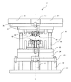
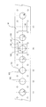
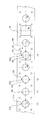
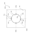
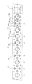
- FIG. 1 is a diagram showing an embodiment of an electric press machine P that presses a processed product
- FIG. 2 is a schematic diagram of an inner slide mechanism of the electric press machine.
- the support 2, the crown 3, and the outer motor 22 are omitted.
- the outer slide mechanism has the same structure as the inner slide mechanism.
- 1 is a bed
- 2 is a column
- 3 is a crown
- 4 is a scale column
- 11 is an inner slide as a first slide
- 12 is an inner motor as a drive source on the first side
- 13 is a first 14 is an inner position detection member as a first side position detection member
- 21 is an outer slide as a second slide
- 22 is an outer slide as a drive source on the second side.
- the bed 1 is a member serving as a base for placing the electric press machine P on the ground.
- the column 2 is a column extending upward from the bed 1.
- the crown 3 is placed on the support 2 and places the inner motor 12 and the outer motor 22.
- a frame of an electric press machine is formed by the bed 1, the support 2, and the crown 3.
- pillar 2 is not restricted to four, but it has at least two or more and the crown 3 should be supported. Moreover, not only a columnar thing but a plate-like thing may be sufficient.
- the inner slide 11 has a pedestal 11a that is movably attached to the support column 2 and a convex portion 11b that extends downward from the pedestal 11a.
- the four corners of the base portion 11a are slidably installed on the support column 2, and the convex portion 11b is installed so as to extend downward from the center of the base portion 11a.
- a plurality of convex portions 11b may extend from the base portion 11a.
- the inner motor 12 is mounted on the crown 3 and drives the inner ball screw 13.
- the inner ball screw 13 has a screw shaft 13a and a nut portion 13b.
- the screw shaft 13 a passes through the crown 3 and is connected to the output shaft of the inner motor 12.
- the nut portion 13b is attached to the inner slide 11 and incorporates a circulating steel ball (not shown).
- inner motors 12 and inner ball screws 13 there are four inner motors 12 and inner ball screws 13 corresponding to the four corners of the crown 3 and the inner slide 11 respectively.
- the four inner motors 12 and the inner ball screw 13 operate independently of each other.
- the number of the inner motor 12 and the inner ball screw 13 is not limited to four, but may be at least two.
- the inner position detection member 14 is preferably a linear scale or the like that reads the scale column 4 and measures the height at which the inner slide 11 is positioned with respect to the bed 1. In the present embodiment, there are four corresponding to the four corners of the inner slide 11. Note that at least two inner position detection members 14 may be provided.
- the outer slide 21 is provided below the inner slide 11 so as to be movably attached to the support column 2 and the convex portion 11b of the inner slide 11 is movable in the vertical direction of the base portion 21a. It has a hole 21b.
- the four corners of the base portion 21a are slidably installed on the support column 2, and the convex portion 11b of the inner slide 11 is slidably passed through the hole 21b in the center of the base portion 21a.
- the outer motor 22 is mounted on the crown 3 and drives the outer ball screw 23.
- the outer ball screw 23 includes a screw shaft 23a and a nut portion 23b.
- the screw shaft 23 a passes through the crown 3 and the inner slide 11 and is connected to the output shaft of the outer motor 22.
- the nut portion 23b is attached to the outer slide 21 and incorporates a circulating steel ball (not shown).
- outer motors 22 and four outer ball screws 23 there are four outer motors 22 and four outer ball screws 23 corresponding to the four corners of the crown 3 and the outer slide 21, respectively.
- the four outer motors 22 and the outer ball screw 23 operate independently.
- the outer motor 22 and the outer ball screw 23 are not limited to four, but may be at least two.
- the outer position detection unit 24 is preferably a linear scale or the like that reads the scale column 4 and measures the height at which the outer slide 21 is positioned with respect to the bed 1. In the present embodiment, there are four corresponding to the four corners of the outer slide 21. Note that there may be at least two outer position detection units 24.
- the scale column 4 is attached to the bed 1 on one side and to the crown 3 on the other side in the vertical direction. In this embodiment, they are attached to the four outer corners of the inner slide 11 and the outer slide 21.
- the inner position detection unit 14 and the outer position detection unit 24 use the scale column 4 in common. Accordingly, the same number of the scale pillars 4, the inner position detection unit 14, and the outer position detection unit 24 are provided.
- the operation of pressing the product to be molded is repeatedly and automatically performed.
- the inner slide 11 and the The outer slide 21 can maintain a horizontal state with high accuracy.
- the inner slide 11 can be kept horizontal at each stage during the progress of each shot of the press process.
- the measurement result of the inner position detecting unit 14 is taken in and determined by adjusting the driving energy supplied to each of the four inner motors 12 that drive the inner slide 11.
- Information on the driving energy supplied to each is stored in the storage device, and (ii) the outer slide 21 is read by taking the measurement result of the outer position detector 24 so that the outer slide 21 can be kept horizontal.
- the drive energy supplied to each of the four outer motors 22 to be driven is adjusted and determined for each stage. Stored in the storage device information on driving energy supplied to each of the outer motor 22.
- the inner slide 11 and the outer slide 21 are maintained in a horizontal state with high accuracy even at each stage of the press working operation for each time.
- the clearance between the four corners of the inner slide 11 and the support column 2 can be determined to be 0.10 mm to 0.25 mm.
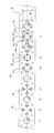
- FIG. 3 is a view showing the vicinity of the die set portion of the electric press machine.
- a die set unit 30 is installed on the bed 1 of the electric press machine P shown in FIG.
- the die set unit 30 includes a lower sub-plate 31 installed above the bed 1, a leg 32 extending upward from the lower sub-plate 31, a lower spacer plate 33 installed on the leg 32, and a lower spacer plate
- the lower spacer 34 installed on the lower spacer 33, the lower die set 35 installed on the lower spacer 34, the guide posts 36 extending upward from the four corners of the lower die set 35, and the guide posts 36 are movably engaged.
- An upper die set 37 having an engagement hole and an upper subplate 38 installed on the upper die set 37 are provided.
- a hydraulic cushion 5 that can control the cushion force by controlling a valve or the like is installed.
- the inner upper mold part 40 is moved by the inner slide 11, and the outer upper mold part 50 is moved by the outer slide 21.
- the first lower mold part 60 is placed on the lower die set 35.
- FIG. 4 is a diagram showing the electric press system of the first embodiment.
- the electric press system 10 includes an electric press machine P and a material installation unit 70.
- the material installation part 70 is a part for installing the material M before processing.
- the material installation part 70 of this embodiment uses a disk-shaped member in which the material M before processing is coiled and wound around the outer periphery.
- the electric press system 10 may include a processing unit (not shown) that processes a part of the material M in advance after being sent from the material installation unit 70 and before being processed by the electric press machine P.
- the processing unit is a unit that processes the material M sent from the laminated material installation unit 70.
- the processing unit processes the material M by progressive feeding, similarly to the techniques described in Patent Document 1 and Patent Document 2.
- the processing machine in the processing unit is not limited to the press machine, and may include a processing machine such as a cutting machine. A plurality of electric press machines P may be used side by side.
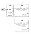
- FIG. 5 is a diagram showing a system configuration of the electric press machine according to the first embodiment.
- the electric press machine P includes an operation panel 6 that is operated by an operator, and a control unit that drives and controls the inner motor 12 and the outer motor 22 of the first to fourth axes in response to commands from the operation panel 6. 7.
- an inner servo amplifier 16 and an outer servo amplifier 26 that receive signals from the control unit 7 to drive and control the inner motor 12 and the outer motor 22, and the inner motor 12 and the outer motor.
- An inner encoder 15 and an outer encoder 25 that detect the number of rotations of the motor 22, and an inner position detector 14 and an outer position detector 24 that detect the positions of the respective axes are provided.
- the control unit 7 includes a command unit 7a that commands a position to the servo amplifiers 16 and 26 corresponding to each axis, and a calculation unit 7b that calculates a command value from the detection values of the position detection units 14 and 24.
- the processed product has an upper surface as a front surface and a lower surface as a rear surface during press working.
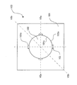
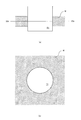
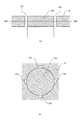
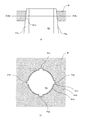
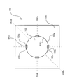
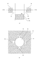
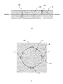
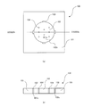
- FIG. 6 shows the processed product of the first embodiment.
- FIG. 7 is a sectional view taken along line VII-VII in FIG. 7A shows a cross section taken along line VIIa-VIIa in FIG. 6, and
- FIG. 7B shows a cross section taken along line VIIb-VIIb in FIG.
- the processed product 100 of the first embodiment includes a first member 101 and a second member 102.
- the first member 101 has an inner peripheral portion 101a formed by making a hole, and an inner peripheral concave portion 101b formed to be recessed from the inner peripheral portion 101a to the outer peripheral side.
- the 2nd member 102 has the outer peripheral part 102a formed by pressing.
- the outer peripheral portion 102 a of the second member 102 has the same shape as the inner peripheral portion 101 a of the first member 101.
- the processed product 100 formed by fitting the second member 102 into the first member 101 is located between the first member 101 and the second member 102 so that the inner peripheral recess 101b corresponds to the front surface to the back surface.
- a slit 103 passing therethrough is formed.
- the processed product 100 according to the first embodiment can have a slit with a minute dimension processed with high accuracy.
- FIG. 8 shows a method for processing a processed product according to the first embodiment.
- FIG. 9 shows the first step of (1) in FIG.
- FIG. 10 shows the second step of (1) in FIG.
- FIG. 11 shows the step (2) of FIG.
- FIG. 12 shows the step (3) of FIG.
- FIG. 13 shows the step (4) of FIG.
- the processed product 100 of the first embodiment is processed from a strip-shaped material M.
- the material M is pressed into a circular shape with the first punch P1 to form holes.
- a part of the inner peripheral portion 101a formed by making the hole is pressed by the convex portion P2a of the second punch P2, and the inner peripheral concave portion 101b recessed on the outer peripheral side is formed.
- a hole S1 is formed in the punched material M.
- the second member 102 formed by pressing the material M with the third punch P3 is supported below.
- the step (2) may be performed simultaneously with or before the step (1).
- step (3) shown in FIG. 8 it is formed in the step (1) above the second member 102 supported below in the step (2) as shown in FIG. As shown in FIG. 12, the second member 102 is pressed and fitted into the hole S1 from below as shown in FIG.
- the press working method according to the first embodiment makes it possible to easily and accurately process a very small slit.
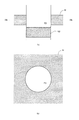
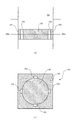
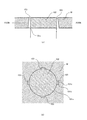
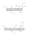
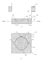
- FIG. 14 shows a processed product of the second embodiment.
- FIG. 15 is a sectional view taken along line XV-XV in FIG. 15A shows the XVaV-XVa cross section of FIG. 14, and FIG. 15B shows the XVb -XVb cross section of FIG.
- the workpiece 100 includes a first member 101 and a second member 102.
- the first member 101 has an inner peripheral portion 101a formed by making a hole, and an inner peripheral concave portion 101b formed to be recessed from the inner peripheral portion 101a to the outer peripheral side.
- the outer outer surface 101c farthest from the inner circumferential portion 101a is formed to be inclined in a taper shape so as to move away from the inner circumferential portion 101a as it goes from the front surface to the back surface.
- the second member 102 has an outer peripheral portion 102a formed by pressing.
- the outer peripheral portion 102 a of the second member 102 has the same shape as the inner peripheral portion 101 a of the first member 101.
- the processed product 100 formed by fitting the second member 102 into the first member 101 is located between the first member 101 and the second member 102 so that the inner peripheral recess 101b corresponds to the front surface to the back surface.
- a slit 103 passing therethrough is formed.
- the processed product 100 of the second embodiment can have a minute dimension slit processed with high accuracy.
- the direction of the slit can be set, and the degree of design freedom can be increased.
- FIG. 16 shows a method for processing a processed product according to the second embodiment.
- FIG. 17 shows the second step of (1) of FIG.
- FIG. 18 shows the step (3) of FIG.
- FIG. 19 shows the step (4) of FIG.
- the workpiece 100 of the second embodiment is processed from a strip-shaped material M.
- the material M is pressed into a circular shape with the first punch P1 to form holes.
- a part of the inner peripheral portion 101a formed by making the hole is pressed by the convex portion P2a of the second punch P2, and the inner peripheral concave portion 101b recessed on the outer peripheral side is formed.
- the outer outer surface 101c farthest from the inner circumferential portion 101a is formed to be inclined in a taper shape so as to move away from the inner circumferential portion 101a as it goes from the front surface to the back surface.
- a hole S1 is formed in the punched material M.
- the second member 102 formed by punching the material M with the third punch P3 is supported below.
- the step (2) may be performed simultaneously with or before the step (1).
- step (3) shown in FIG. 16 it is formed in the step (1) above the second member 102 supported below in the step (2) as shown in FIG. As shown in FIG. 18, the second member 102 is pressed and fitted into the hole S1 from below as shown in FIG.
- the press working method according to the second embodiment makes it possible to easily and accurately process a very small slit. Further, even if the direction of the slit and the direction in which the second member is fitted into the first member intersect, it can be easily processed with high accuracy.
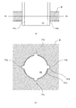
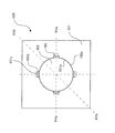
- FIG. 20 shows a processed product of the third embodiment.
- FIG. 21 is a sectional view taken along line XXI-XXI in FIG.
- FIG. 21A shows a cross section along XXIaXI-XXIa of FIG. 20, and
- FIG. 21B shows a cross section along XXIb -XXIb of FIG.
- the workpiece 100 includes a first member 101 and a second member 102.
- the first member 101 has an inner peripheral portion 101a formed by making a hole, and an inner peripheral concave portion 101b formed to be recessed from the inner peripheral portion 101a to the outer peripheral side.
- the outer outer surface 101c farthest from the inner circumferential portion 101a is formed to be inclined in a taper shape so as to move away from the inner circumferential portion 101a as it goes from the front surface to the back surface.
- the second member 102 has an outer peripheral portion 102a formed by pressing and an outer peripheral concave portion 102b formed to be recessed from the outer peripheral portion 102a toward the inner peripheral side.
- the inner inner surface 102c farthest from the outer circumferential portion 102a is formed to be inclined in a tapered shape so as to approach the outer circumferential portion 102a from the front surface to the back surface.
- the outer peripheral part 102 a of the second member 102 has the same shape as the inner peripheral part 101 a of the first member 101. Therefore, in the workpiece 100 formed by fitting the second member 102 into the first member 101, the inner peripheral recess 101 b and the outer peripheral recess 102 b are positioned between the first member 101 and the second member 102. A slit 103 penetrating from the front surface to the back surface is formed.
- the processed product 100 according to the third embodiment can have a slit with a minute dimension processed with high accuracy.
- the direction of the slit can be set, and the degree of design freedom can be increased.
- FIG. 22 shows a method for processing a processed product according to the third embodiment.
- FIG. 23 shows the step (2) of FIG.
- FIG. 24 shows the step (4) of FIG.
- FIG. 25 shows the step (5) of FIG.
- FIG. 26 shows the step (6) of FIG.
- FIG. 27 shows the step (7) of FIG.
- the workpiece 100 of the second embodiment is processed from a strip-shaped material M.
- the material M is pressed into a circular shape with the first punch P1 to form holes.
- a part of the inner peripheral portion 101a formed by making the hole is pressed by the convex portion P2a of the second punch P2, and the inner peripheral concave portion 101b recessed on the outer peripheral side is formed.
- a hole S1 is formed in the punched material M.
- the material M is pressed by the third punch P3 as shown in FIG. A hole S2 is formed in the punched material M.
- the step (2) may be performed simultaneously with or before the step (1).
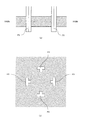
- the outer outer surface 101c farthest from the inner peripheral portion 101a of the inner peripheral recess 101b is directed from the front surface to the rear surface. Accordingly, it is formed to be inclined in a tapered shape so as to be away from the inner peripheral portion 101a.
- the inner side surfaces 102c close to the centers Sc of the four holes S2 of the material M formed in the step (2) are formed.
- a taper is formed by the fourth punch P4 so as to move away from the center Sc of the four holes S2 as it goes from the front surface to the back surface.
- the step (4) may be performed simultaneously with or before the step (3).
- the second member 102 formed by pressing the material M with the fifth punch P5 is supported below.
- the second member 102 is punched out so as to include the inner surface 102c formed in the step (4).
- step (6) shown in FIG. 22 it is formed in the step (3) above the second member 102 supported below in the step (5) as shown in FIG.
- the hole S1 is moved, and the second member 102 is pressed and fitted into the hole S1 from below as shown in FIG.
- the press working method according to the third embodiment makes it possible to easily and accurately process a very small slit. Further, even if the direction of the slit and the direction in which the second member is fitted into the first member intersect, it can be easily processed with high accuracy.
- FIG. 28 shows a processed product of the fourth embodiment.
- FIG. 29 shows a cross-sectional view of FIG. 29A shows a section XXIXa--XXIXa in FIG. 28, and
- FIG. 29B shows a section XXIXb--XXIXb in FIG.
- the processed product 100 of the fourth embodiment includes a first member 101 and a second member 102.
- the first member 101 has an inner peripheral portion 101a formed by making a hole, and an inner peripheral concave portion 101b formed to be recessed from the inner peripheral portion 101a to the outer peripheral side.
- the outer outer surface 101c farthest from the inner circumferential portion 101a is formed to be inclined in a taper shape so as to move away from the inner circumferential portion 101a as it goes from the front surface to the back surface.
- the second member 102 includes an outer peripheral portion 102a formed by pressing and an outer peripheral concave portion 102b that is recessed from the outer peripheral portion 102a toward the inner peripheral side.
- the inner inner surface 102c farthest from the outer circumferential portion 102a is formed to be inclined in a tapered shape so as to move away from the outer circumferential portion 102a from the front surface to the back surface.
- the outer peripheral part 102 a of the second member 102 has the same shape as the inner peripheral part 101 a of the first member 101. Therefore, in the workpiece 100 formed by fitting the second member 102 into the first member 101, the inner peripheral recess 101 b and the outer peripheral recess 102 b are positioned between the first member 101 and the second member 102. A slit 103 penetrating from the front surface to the back surface is formed.
- the processed product 100 according to the fourth embodiment can have a slit with a minute dimension that is processed with high accuracy.
- the direction of the slit can be set, and the degree of design freedom can be increased.
- FIG. 30 shows a method for processing a processed product according to the fourth embodiment.
- FIG. 31 shows the step (4) of FIG.
- FIG. 32 shows the step (5) of FIG.
- FIG. 33 shows the step (6) of FIG.
- FIG. 34 shows a step (7) in FIG.
- the processed product 100 of the fourth embodiment is processed from a strip-shaped material M.
- the material M is pressed into a circular shape with the first punch P1 to form holes.
- a part of the inner peripheral portion 101a formed by making the hole is pressed by the convex portion P2a of the second punch P2, and the inner peripheral concave portion 101b recessed on the outer peripheral side is formed.
- a hole S1 is formed in the punched material M.
- the material M is pressed by the third punch P3 as shown in FIG. A hole S2 is formed in the punched material M.
- the step (2) may be performed simultaneously with or before the step (1).
- the outer outer surface 101c farthest from the inner peripheral portion 101a of the inner peripheral recess 101b is directed from the front surface to the rear surface. Accordingly, it is formed so as to be inclined in a tapered shape so as to be away from the inner peripheral portion 101a.
- the inner side surfaces 102c close to the centers Sc of the four holes S2 of the material M formed in the step (2) are formed.
- the taper is formed by the fourth punch P4 so as to approach the center Sc of the four holes S2 from the front surface to the back surface.
- the step (4) may be performed simultaneously with or before the step (3).
- the second member 102 formed by punching the material M with the fifth punch P5 is supported below.
- the second member 102 is punched out so as to include the inner surface 102c formed in the step (4).
- step (6) shown in FIG. 30 it is formed in the step (3) above the second member 102 that was supported below in the step (5).
- the second member 102 is pressed and fitted into the hole S1 from below.
- the press working method according to the fourth embodiment makes it possible to easily and accurately process a very small slit. Further, even if the direction of the slit and the direction in which the second member is fitted into the first member intersect, it can be easily processed with high accuracy.
- FIG. 35 shows a processed product of the fifth embodiment.
- FIG. 36 shows a cross section taken along line XXXVI-XXXVI of FIG. A cross-sectional view is shown.
- 36A shows a section XXXVIaVI-XXXVIa in FIG. 35
- FIG. 36B shows a section XXXVIb -XXXVIb in FIG.
- the processed product 100 of the fifth embodiment includes a first member 101 and a second member 102.
- the first member 101 has an inner peripheral portion 101a formed by making a hole and an inner peripheral concave portion 101b that is recessed from the inner peripheral portion 101a to the outer peripheral side.
- the outer outer surface 101c farthest from the inner circumferential portion 101a is formed to be inclined in a tapered shape so as to approach the inner circumferential portion 101a as it goes from the front surface to the back surface.
- the second member 102 has an outer peripheral portion 102a formed by pressing and an outer peripheral concave portion 102b that is recessed from the outer peripheral portion 102a to the inner peripheral side.
- the inner inner surface 102c farthest from the outer circumferential portion 102a is formed to be inclined in a tapered shape so as to move away from the outer circumferential portion 102a from the front surface to the back surface.
- the outer peripheral part 102 a of the second member 102 has the same shape as the inner peripheral part 101 a of the first member 101. Therefore, in the workpiece 100 formed by fitting the second member 102 into the first member 101, the inner peripheral recess 101 b and the outer peripheral recess 102 b are positioned between the first member 101 and the second member 102. A slit 103 penetrating from the front surface to the back surface is formed.
- the processing method used for the processed product of the third embodiment may be performed in the opposite direction.
- the processed product 100 of the fifth embodiment can have a slit with a minute dimension that is processed with high accuracy.
- the direction of the slit can be set, and the degree of design freedom can be increased.
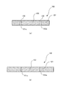
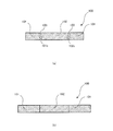
- FIG. 37 shows a cross-sectional view of the processed product of the sixth embodiment.
- the processed product 100 of the sixth embodiment includes an inner circumferential recess 101b of the first member 101 in the slit 103 formed between the first member 101 and the second member 102.
- the inner inner surface 102c farthest from the outer peripheral portion 102a is formed by a curved surface.
- the outer surface 101c of the first member 101 is formed so as to move away from the inner peripheral portion 101a as it goes from the front surface to the back surface.
- the inner surface 102c of the second member 102 is formed so as to approach the outer peripheral portion 102a as it goes from the front surface to the back surface.
- the processed product 100 according to the sixth embodiment can have a slit with a minute dimension processed with high accuracy. Further, the direction and shape of the slit can be set, and the degree of design freedom can be further increased.
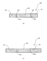
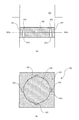
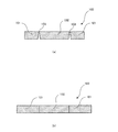
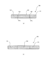
- FIG. 38 shows a processed product of the seventh embodiment.
- FIG. 38 (a) shows a plan view of the processed product
- FIG. 37 (b) shows a XXXIIXb-XXXIIXb cross section of FIG. 38 (a).
- At least one through hole 104 is formed in the second member 102.
- the through-hole 104 it is possible to adjust the amount of fluid or powder ejected.
Landscapes
- Engineering & Computer Science (AREA)
- Mechanical Engineering (AREA)
- Shaping Metal By Deep-Drawing, Or The Like (AREA)
- Punching Or Piercing (AREA)
- Perforating, Stamping-Out Or Severing By Means Other Than Cutting (AREA)
Priority Applications (2)
| Application Number | Priority Date | Filing Date | Title |
|---|---|---|---|
| EP16879041.8A EP3395467B1 (en) | 2015-12-24 | 2016-12-26 | Machined article and press-machining method |
| US16/014,229 US11633774B2 (en) | 2015-12-24 | 2018-06-21 | Machined article and pressing method |
Applications Claiming Priority (2)
| Application Number | Priority Date | Filing Date | Title |
|---|---|---|---|
| JP2015251427A JP6164757B2 (ja) | 2015-12-24 | 2015-12-24 | 加工品及びプレス加工方法 |
| JP2015-251427 | 2015-12-24 |
Related Child Applications (1)
| Application Number | Title | Priority Date | Filing Date |
|---|---|---|---|
| US16/014,229 Continuation US11633774B2 (en) | 2015-12-24 | 2018-06-21 | Machined article and pressing method |
Publications (1)
| Publication Number | Publication Date |
|---|---|
| WO2017111157A1 true WO2017111157A1 (ja) | 2017-06-29 |
Family
ID=59090626
Family Applications (1)
| Application Number | Title | Priority Date | Filing Date |
|---|---|---|---|
| PCT/JP2016/088672 Ceased WO2017111157A1 (ja) | 2015-12-24 | 2016-12-26 | 加工品及びプレス加工方法 |
Country Status (4)
| Country | Link |
|---|---|
| US (1) | US11633774B2 (enExample) |
| EP (1) | EP3395467B1 (enExample) |
| JP (1) | JP6164757B2 (enExample) |
| WO (1) | WO2017111157A1 (enExample) |
Families Citing this family (4)
| Publication number | Priority date | Publication date | Assignee | Title |
|---|---|---|---|---|
| DE102016201433A1 (de) * | 2016-02-01 | 2017-08-03 | Bayerische Motoren Werke Aktiengesellschaft | Verfahren zum Bearbeiten und/oder Herstellen eines Bauteils |
| CN108555061A (zh) * | 2018-06-23 | 2018-09-21 | 东莞理工学院 | 一种能够健康维护的压平切块收集一体机 |
| DE102018131166B4 (de) * | 2018-12-06 | 2020-08-13 | Johannes Hülshorst | Feinschneidpresse |
| CN114289605B (zh) * | 2021-11-29 | 2024-08-13 | 邳州华创新能源电池研究院有限公司 | 一种可自动下料用于新能源汽车锂电池底板的冲压机构 |
Citations (4)
| Publication number | Priority date | Publication date | Assignee | Title |
|---|---|---|---|---|
| DE10131474A1 (de) * | 2001-06-29 | 2003-05-28 | Bosch Gmbh Robert | Elektrische Maschine |
| JP4220590B2 (ja) | 1998-06-04 | 2009-02-04 | 株式会社放電精密加工研究所 | 微小寸法の穴および/またはスリットを有する製品の製造方法 |
| JP2014054674A (ja) * | 2013-11-22 | 2014-03-27 | Hoden Seimitsu Kako Kenkyusho Ltd | 電動プレス加工機によって成形される被成形品 |
| JP2014073046A (ja) * | 2012-10-01 | 2014-04-21 | Kuroda Precision Ind Ltd | 積層鉄心の製造方法および積層鉄心製造装置 |
Family Cites Families (8)
| Publication number | Priority date | Publication date | Assignee | Title |
|---|---|---|---|---|
| NL240989A (enExample) * | 1958-07-11 | 1900-01-01 | ||
| US3074299A (en) * | 1958-10-22 | 1963-01-22 | Sylvania Electric Prod | Swage plate |
| NL135002C (enExample) * | 1965-12-16 | |||
| US3534466A (en) * | 1967-04-18 | 1970-10-20 | Edward J Ardolino | Method of fastening sheet material |
| US4728842A (en) * | 1986-09-29 | 1988-03-01 | Carbet Corporation | Laminated assembly for a dynamoelectric machine and method for manufacturing laminated assemblies having ridges formed on projections which interlock with recesses of adjacent laminations |
| JP2001029479A (ja) * | 1999-07-23 | 2001-02-06 | Asahi Optical Co Ltd | 内視鏡用噴霧具 |
| US7235910B2 (en) * | 2003-04-25 | 2007-06-26 | Metglas, Inc. | Selective etching process for cutting amorphous metal shapes and components made thereof |
| US8159094B2 (en) * | 2009-03-11 | 2012-04-17 | Nidec Motor Corporation | Electric motor having fluid circulation system and methods for cooling an electric motor |
-
2015
- 2015-12-24 JP JP2015251427A patent/JP6164757B2/ja active Active
-
2016
- 2016-12-26 WO PCT/JP2016/088672 patent/WO2017111157A1/ja not_active Ceased
- 2016-12-26 EP EP16879041.8A patent/EP3395467B1/en active Active
-
2018
- 2018-06-21 US US16/014,229 patent/US11633774B2/en active Active
Patent Citations (4)
| Publication number | Priority date | Publication date | Assignee | Title |
|---|---|---|---|---|
| JP4220590B2 (ja) | 1998-06-04 | 2009-02-04 | 株式会社放電精密加工研究所 | 微小寸法の穴および/またはスリットを有する製品の製造方法 |
| DE10131474A1 (de) * | 2001-06-29 | 2003-05-28 | Bosch Gmbh Robert | Elektrische Maschine |
| JP2014073046A (ja) * | 2012-10-01 | 2014-04-21 | Kuroda Precision Ind Ltd | 積層鉄心の製造方法および積層鉄心製造装置 |
| JP2014054674A (ja) * | 2013-11-22 | 2014-03-27 | Hoden Seimitsu Kako Kenkyusho Ltd | 電動プレス加工機によって成形される被成形品 |
Non-Patent Citations (1)
| Title |
|---|
| See also references of EP3395467A4 |
Also Published As
| Publication number | Publication date |
|---|---|
| JP6164757B2 (ja) | 2017-07-19 |
| EP3395467A1 (en) | 2018-10-31 |
| JP2017113780A (ja) | 2017-06-29 |
| EP3395467B1 (en) | 2020-08-12 |
| US20180297100A1 (en) | 2018-10-18 |
| US11633774B2 (en) | 2023-04-25 |
| EP3395467A4 (en) | 2019-08-14 |
Similar Documents
| Publication | Publication Date | Title |
|---|---|---|
| JP6164757B2 (ja) | 加工品及びプレス加工方法 | |
| JP4751477B1 (ja) | 工作機械におけるワーククランプ装置 | |
| TWI233883B (en) | Progressive processing device | |
| JP6129753B2 (ja) | 2つのワークスピンドルを備えた機械加工ユニット | |
| KR101791401B1 (ko) | 전동 프레스 가공기의 작동 방법 | |
| US20100260569A1 (en) | Mill bed | |
| KR102023880B1 (ko) | 적층 장치 및 적층체 제조 시스템 | |
| JP6532127B2 (ja) | 電動プレス加工機 | |
| JP2012091262A (ja) | 加工装置 | |
| JP6164760B1 (ja) | 螺旋状コイル製造方法 | |
| KR101658780B1 (ko) | 목형 금형 5축 제어용 밀링 | |
| JP2014054674A (ja) | 電動プレス加工機によって成形される被成形品 | |
| JP6006550B2 (ja) | ステージ構造およびステージ構造を加工する方法 | |
| KR102715971B1 (ko) | 튜브 시트 머시닝 지그 | |
| KR20080109230A (ko) | 공작 기계 및 그 제어 방법 | |
| CN210549652U (zh) | 电流针主体用治具 | |
| JP2017177193A (ja) | 部分ユニット式金型構造 | |
| JP2002036023A (ja) | プレス機におけるスライド下面修正方法と装置 | |
| JP2019089170A (ja) | 工作機械および工作機械の制御方法 | |
| JP2008284596A (ja) | 高速軸送り手段を備えたパンチプレス及び同装置を用いた高速ニブリング加工方法 |
Legal Events
| Date | Code | Title | Description |
|---|---|---|---|
| 121 | Ep: the epo has been informed by wipo that ep was designated in this application |
Ref document number: 16879041 Country of ref document: EP Kind code of ref document: A1 |
|
| NENP | Non-entry into the national phase |
Ref country code: DE |
|
| WWE | Wipo information: entry into national phase |
Ref document number: 2016879041 Country of ref document: EP |
|
| ENP | Entry into the national phase |
Ref document number: 2016879041 Country of ref document: EP Effective date: 20180724 |