EP3395467B1 - Machined article and press-machining method - Google Patents
Machined article and press-machining method Download PDFInfo
- Publication number
- EP3395467B1 EP3395467B1 EP16879041.8A EP16879041A EP3395467B1 EP 3395467 B1 EP3395467 B1 EP 3395467B1 EP 16879041 A EP16879041 A EP 16879041A EP 3395467 B1 EP3395467 B1 EP 3395467B1
- Authority
- EP
- European Patent Office
- Prior art keywords
- peripheral portion
- inner peripheral
- outer peripheral
- pressing
- machined article
- Prior art date
- Legal status (The legal status is an assumption and is not a legal conclusion. Google has not performed a legal analysis and makes no representation as to the accuracy of the status listed.)
- Active
Links
Images


Classifications
-
- B—PERFORMING OPERATIONS; TRANSPORTING
- B21—MECHANICAL METAL-WORKING WITHOUT ESSENTIALLY REMOVING MATERIAL; PUNCHING METAL
- B21D—WORKING OR PROCESSING OF SHEET METAL OR METAL TUBES, RODS OR PROFILES WITHOUT ESSENTIALLY REMOVING MATERIAL; PUNCHING METAL
- B21D28/00—Shaping by press-cutting; Perforating
- B21D28/24—Perforating, i.e. punching holes
- B21D28/26—Perforating, i.e. punching holes in sheets or flat parts
-
- B—PERFORMING OPERATIONS; TRANSPORTING
- B21—MECHANICAL METAL-WORKING WITHOUT ESSENTIALLY REMOVING MATERIAL; PUNCHING METAL
- B21D—WORKING OR PROCESSING OF SHEET METAL OR METAL TUBES, RODS OR PROFILES WITHOUT ESSENTIALLY REMOVING MATERIAL; PUNCHING METAL
- B21D28/00—Shaping by press-cutting; Perforating
- B21D28/24—Perforating, i.e. punching holes
-
- B—PERFORMING OPERATIONS; TRANSPORTING
- B21—MECHANICAL METAL-WORKING WITHOUT ESSENTIALLY REMOVING MATERIAL; PUNCHING METAL
- B21D—WORKING OR PROCESSING OF SHEET METAL OR METAL TUBES, RODS OR PROFILES WITHOUT ESSENTIALLY REMOVING MATERIAL; PUNCHING METAL
- B21D37/00—Tools as parts of machines covered by this subclass
- B21D37/08—Dies with different parts for several steps in a process
-
- B—PERFORMING OPERATIONS; TRANSPORTING
- B21—MECHANICAL METAL-WORKING WITHOUT ESSENTIALLY REMOVING MATERIAL; PUNCHING METAL
- B21D—WORKING OR PROCESSING OF SHEET METAL OR METAL TUBES, RODS OR PROFILES WITHOUT ESSENTIALLY REMOVING MATERIAL; PUNCHING METAL
- B21D39/00—Application of procedures in order to connect objects or parts, e.g. coating with sheet metal otherwise than by plating; Tube expanders
- B21D39/03—Application of procedures in order to connect objects or parts, e.g. coating with sheet metal otherwise than by plating; Tube expanders of sheet metal otherwise than by folding
Definitions
- the present invention relates to a machined article for jetting fluid or powder from small holes, and a pressing method for machining the machined article.
- Patent Literatures 1-3 a technique for forming holes of minute dimensions by engaging and integrating a plurality of plate-like members shaped by punching.
- Patent Literature 1 needs a long machining time since the holes are formed by stacking a plurality of plate-like members.
- An object of the present invention is to propose a machined article having a precisely-machined slit of minute dimensions and a pressing method capable of easily and precisely machining the slit of minute dimensions.
- a machined article according to the present invention includes:
- the machined article according to the present invention is characterized in that an outer side surface of the inner peripheral recess at an outer side farthest from the inner peripheral portion or an inner side surface of the outer peripheral recess at an inner side farthest from the outer peripheral portion intersects with a direction of fitting of the second member into the first member.
- the machined article according to the present invention is characterized in that the outer side surface or the inner side surface is oblique to the direction of fitting.
- the machined article according to the present invention is characterized in that the outer side surface and the inner side surface are formed opposite to each other.
- the machined article according to the present invention is characterized in that the outer side surface and the inner side surface are formed in parallel.
- a pressing method according to the present invention includes the steps of:
- a pressing method according to the present invention includes the steps of:
- a pressing method according to the present invention includes the steps of:
- the pressing method according to the present invention is characterized in that an outer side surface of the inner peripheral recess at an outer side farthest from the inner peripheral portion and an inner side surface of the outer peripheral recess at an inner side farthest from the outer peripheral portion intersect with a direction of fitting of the second member into the first member.
- the pressing method according to the present invention is characterized in that the outer side surface or the inner side surface is oblique to the direction of fitting.
- the pressing method according to the present invention is characterized in that the outer side surface and the inner side surface are formed opposite to each other.
- the pressing method according to the present invention is characterized in that the outer side surface and the inner side surface are formed in parallel.
- a machined article having a precisely-machined slit of minute dimensions and a pressing method capable of easily and precisely machining the slit of minute dimensions can be provided.
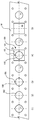
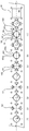
- FIG. 1 is a diagram illustrating an embodiment of an electric press machine P for pressing a machined article.
- FIG. 2 is a schematic diagram of an inner slide mechanism of the electric press machine. In FIG. 2 , supports 2, a crown 3, and outer motors 22 are omitted. An outer slide mechanism has a similar structure to that of the inner slide mechanism.
- FIG. 1 illustrates a bed 1, the supports 2, the crown 3, scale columns 4, an inner slide 11 serving as a first slide, inner motors 12 serving as first-side driving sources, inner ball screws 13 serving as first-side feed members, inner position detection members 14 serving as first-side position detection members, an outer slide 21 serving as a second slide, outer motors 22 serving as second-side driving sources, outer ball screws 23 serving as second second-side feed members, and outer position detection members 24 serving as second-side position detection members.
- the bed 1 is a member serving as a base for placing the electric press machine P on the ground.
- the supports 2 are columns extending upward from the bed 1. In the present embodiments, there are four supports 2 which are arranged at the respective four corners of the bed 1.
- the crown 3 is placed on the supports 2, and the inner motors 12 and the outer motors 22 are placed thereon.
- the bed 1, the supports 2, and the crown 3 form a frame of the electric press machine.
- the supports 2 are not limited to four in number. At least two or more supports 2 can be provided to support the crown 3.
- the supports 2 are not limited to column-shaped ones and may be plate-shaped ones.
- the inner slide 11 includes a table-like portion 11a which is movably attached to the supports 2, and a protrusion 11b which extends downward from the table-like portion 11a.
- the four corners of the table-like portion 11a are slidably arranged on the supports 2, and the protrusion 11b is arranged to extend downward from the center of the table-like portion 11a.
- a plurality of protrusions 11b may be extended from the table-like portion 11a.
- the inner motors 12 are placed on the crown 3 and drive the inner ball screws 13.
- the inner ball screws 13 each include a screw shaft 13a and a nut portion 13b.
- the screw shafts 13a are passed through the crown 3 and coupled to the output shafts of the inner motors 12.
- the nut portions 13b are attached to the inner slide 11, and include non-illustrated circulating steel balls inside.
- the four inner motors 12 and the four inner ball screws 13 each operate independently. Neither the inner motors 12 nor the inner ball screws 13 are limited to four in number. There may be at least two or more inner motors 12 and two or more inner ball screws 13.
- the inner position detection members 14 may preferably be linear scales or the like for reading the scale columns 4 to measure the height at which the inner slide 11 is located with respect to the bed 1. In the present embodiment, there are four inner position detection members 14 corresponding to the four corners of the inner slide 11. There may be at least two or more inner position detection members 14.
- the outer slide 21 includes a table-like portion 21a which is movably attached to the supports 2 under the inner slide 11, and a hole portion 21b through which the protruded portion 11b of the inner slide 11 is movably passed in an up-and-down direction of the table-like portion 21a.
- the four corners of the table-like portion 21a are slidably arranged on the supports 2.
- the hole portion 21b is provided in the center of the table-like portion 21a so that the protrusion 11b of the inner slide 11 is slidably passed through.
- the outer motors 22 are placed on the crown 3 and drive the outer ball screws 23.
- the outer ball screws 23 each include a screw shaft 23a and a nut portion 23b.
- the screw shafts 23a are passed through the crown 3 and the inner slide 11, and coupled to the output shafts of the outer motors 22.
- the nut portions 23b are attached to the outer slide 21, and include non-illustrated circulating steel balls inside.
- the four outer motors 22 and the four outer ball screws 23 each operate independently. Neither the outer motors 22 nor the outer ball screws 23 are limited to four in number. There may be at least two or more outer motors 22 and two or more outer ball screws 23.
- the outer position detection units 24 may preferably be linear scales or the like for reading the scale columns 4 to measure the height at which the outer slide 21 is located with respect to the bed 1. In the present embodiment, there are four outer position detection units 24 corresponding to the four corners of the outer slide 21. There may be at least two or more outer position detection units 24.
- the scale columns 4 are perpendicularly attached to the bed 1 at one end and to the crown 3 at the other end each. In the present embodiment, the scale columns 4 are attached to the four outer corners of the inner slide 11 and the outer slide 21.
- the inner position detection units 14 and the outer position detection units 24 use the scale columns 4 in common.
- the scale columns 4, the inner position detection units 14, and the outer position detection units 24 are therefore provided in the same numbers.
- an operation of pressing an article to be molded is automatically repeated.
- the inner slide 11 and the outer slide 21 can be precisely maintained in a horizontal state at each stage of each pressing operation.
- each of the inner motors 12 for driving the inner slide 11 is supplied with driving energy based on the stored information
- each of the outer motors 22 for driving the outer slide 21 is supplied with driving energy based on the stored information.
- such control is performed to precisely maintain the inner slide 11 and the outer slide 21 in a horizontal state even at each stage of each pressing operation.
- clearances between the sliding holes in the four corners of the slide 11 and the supports 2 can be determined to be 0.10 mm to 0.25 mm.
- FIG. 3 is a diagram illustrating the vicinity of a die set unit of the electric press machine.
- the die set unit 30 is arranged on the bed 1 of the electric press machine P illustrated in FIG. 1 .
- the die set unit 30 includes a lower sub plate 31 which is arranged above the bed 1, leg portions 32 which extend upward from the lower sub plate 33, a lower spacer plate 33 which is arranged on the leg portions 33, a lower spacer 34 which is arranged on the lower spacer plate 33, a lower die set 35 which is arranged on the lower spacer 34, guide posts 36 which extend upward from the four corners of the lower die set 35, an upper die set 37 having engagement holes with which the guide posts 36 are movably engaged, and an upper sub plate 38 which is arranged on the upper die set 37.
- a hydraulic cushion 5 which can control cushioning force by controlling a valve or the like is also arranged on the lower sub plate 31.
- An inner upper die unit 40 is moved by the inner slide 11.
- An outer upper die unit 50 is moved by the outer slide 21.
- a first lower die unit 60 is placed on the lower die set 35.
- FIG. 4 is a diagram illustrating an electric press system according to the first embodiment.
- An electric press system 10 includes the electric press machine P and a material installation unit 70.
- the material installation unit 70 is a section in which a material M yet to be machined is installed.
- the material installation unit 70 according to the present embodiment uses a disk around the outer periphery of which the material M yet to be machined is wound in a coil form.
- the electric press system 10 may include a non-illustrated machining unit that machines part of the material M fed from the material installation unit 70 in advance before being machined by the electric press machine P.
- the machining unit is a unit for machining the material M fed from the to-be-stacked material installation unit 70. Like the technique described in Patent Literature 1 and Patent Literature 2, the machining unit machines the material M in a progressive manner.
- the machine in the machining unit is not limited to a press machine, and may include a cutter or other machine. A plurality of electric press machines P may be used in a row.
- FIG. 5 is a diagram illustrating a system configuration of the electric press machine according to the first embodiment.
- the electric press machine P includes an operation console 6 which is operated by an operator, and a control unit 7 which drives and controls the inner motors 12 and the outer motors 22 of first to fourth axes according to commands from the operation console 6.
- the electric press machine P also includes, corresponding to the respective axes, inner servo amplifiers 16 and outer servo amplifiers 26 which receive signals from the control unit 7 and drive and control the inner motors 12 and the outer motors 22, inner encoders 15 and outer encoders 25 which detect the numbers of rotations of the inner motors 12 and the outer motors 22, and the inner position detection units 14 and the outer position detection units 24 which detect the positions of the respective axes.
- the control unit 7 includes a command unit 7a which gives commands about positions to the servo amplifiers 16 and 26 corresponding to the respective axes, and an arithmetic unit 7b which calculates command values from the detection values of the position detection units 14 and 24.
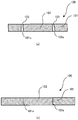
- the upper surface of a machined article during pressing will be referred to as the front, and the lower surface the back.
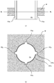
- FIG. 6 illustrates a machined article according to the first embodiment not covered by the invention • FIGS. 7(a) and 7(b) illustrate sectional views taken along lines VII-VII of FIG. 6 .
- FIG. 7(a) illustrates a VIIa-VIIa section of FIG. 6 .
- FIG. 7(b) illustrates a VIIb-VIIb section of FIG. 6 .
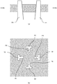
- a machined article 100 includes a first member 101 and a second member 102.
- the first member 101 includes an inner peripheral portion 101a which is formed by perforation, and inner peripheral recesses 101b which are dented radially outward from the inner peripheral portion 101a.
- the second member 102 includes an outer peripheral portion 102a which is formed by pressing.
- the outer peripheral portion 102a of the second member 102 has the same shape as that of the inner peripheral portion 101a of the first member 101.
- the machined article 100 which is formed by fitting the second member 102 into the first member 101 forms slits 103 penetrating from the front to the back at positions to which the inner peripheral recesses 101b correspond, between the first member 101 and the second member 102.
- the machined article 100 according to the first embodiment can thus have precisely-machined slits of minute dimensions.
- FIGS. 8(1) to 8(5) illustrate a machining method of the machined article according to the first embodiment not covered by the invention.
- FIGS. 9(a) and 9(b) illustrate a first step of FIG. 8(1) .
- FIGS. 10(a) and 10(b) illustrate a second step of FIG. 8(1) .
- FIGS. 11(a) and 11(b) illustrate the step of FIG. 8 (2).
- FIGS. 12(a) and 12(b) illustrate the step of FIG. 8(3) .
- FIGS. 13(a) and 13(b) illustrate the step of FIG. 8(4) .
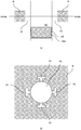
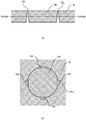
- the machined article 100 according to the first embodiment is formed by machining a band of material M.
- the material M is circularly pressed by a first punch P1 to form a hole.
- part of the inner peripheral portion 101a formed by perforation is pressed by protrusions P2a of a second punch P2 to form the inner peripheral recesses 101b which are dented radially outward.
- a hole S1 is formed in the punched material M.
- a second member 102 formed by pressing the material M by a third punch P3 is supported below.
- the step of (2) may be performed simultaneously with or before the step of (1).
- the hole S1 formed in the step of (1) is moved to above the second member 102 supported below in the step of (2) as illustrated in FIGS. 11(a) and 11(b) .
- the second member 102 is pressed and fitted into the hole S1 from below.
- the pressing method according to the first embodiment can easily and precisely machine the slits of minute dimensions.
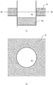
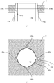
- FIG. 14 illustrates a machined article according to a second embodiment.
- FIGS. 15 (a) and 15 (b) illustrate sectional views taken along lines XV-XV of FIG. 14 .
- FIG. 15(a) illustrates a XVa-XVa section of FIG. 14 .
- FIG. 15(b) illustrates a XVb-XVb section of FIG. 14 .
- a machined article 100 includes a first member 101 and ad second member 102.
- the first member 101 includes an inner peripheral portion 101a which is formed by perforation, and inner peripheral recesses 101b which are dented radially outward from the inner peripheral portion 101a.
- Outer side surfaces 101c of the inner peripheral recesses 101b at outer sides farthest from the inner peripheral portion 101a are obliquely formed in a tapered shape to get away from the inner peripheral portion 101a from the front to the back.
- the second portion 102 includes an outer peripheral portion 102a which is formed by pressing.
- the outer peripheral portion 102a of the second member 102 has the same shape as that of the inner peripheral portion 101a of the first member 101.
- the machined article 100 which is formed by fitting the second member 102 into the first member 101 forms slits 103 penetrating from the front to the back at positions to which the inner peripheral recesses 101b correspond, between the first member 101 and the second member 102.
- the machined article 100 according to the second embodiment can thus have the precisely-machined slits of minute dimensions.
- the directions of the slits can be set to increase the degree of freedom of design.
- FIGS. 16(1) to 16(4) illustrate a machining method of the machined article according to the second embodiment.
- FIGS. 17(a) and 17(b) illustrate a second step of FIG. 16(1) .
- FIGS. 18(a) and 18(b) illustrate the step of FIG. 16(3) .
- FIGS. 19(a) and 19(b) illustrate the step of FIG. 16(4) .
- the machined article 100 according to the second embodiment is formed by machining a band of material M.
- the material M is circularly pressed by the first punch P1 to form a hole.
- part of the inner peripheral portion 101a formed by perforation is pressed by protrusions P2a of a second punch P2 to form the inner peripheral recesses 101b dented radially outward.
- Outer side surfaces 101c of the inner peripheral recesses 101a at outer sides farthest from the inner peripheral portion 101a are obliquely formed in a tapered shape to get away from the inner peripheral portion 101a from the front to the back.
- a hole S1 is formed in the punched material M.
- a second member 102 formed by punching the material M by the third punch P3 is supported below.
- the step of (2) may be performed simultaneously with or before the step of (1).
- the hole S1 formed in the step of (1) is moved to above the second member 102 supported below in the step of (2) as illustrated in FIGS. 11 (a) and 11(b) .
- the second member 102 is pressed and fitted into the hole S1 from below.
- the pressing method according to the second embodiment can easily and precisely machine the slits of minute dimensions.
- the slits can be easily and precisely machined even if the directions of the slits intersect with the direction of fitting of the second member into the first member.
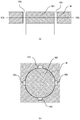
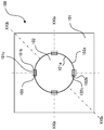
- FIG. 20 illustrates a machined article according to a third embodiment.
- FIGS. 21 (a) and 21 (b) illustrate sectional views taken along lines XXI-XXI of FIG. 20 .
- FIG. 21(a) illustrates a XXIa-XXIa cross section of FIG. 20 .
- FIG. 21(b) illustrates a XXIb-XXIb cross section of FIG. 20 .
- a machined article 100 includes a first member 101 and a second member 102.
- the first member 101 includes an inner peripheral portion 101a which is formed by perforation, and inner peripheral recesses 101b which are dented radially outward from the inner peripheral portion 101a.
- Outer side surfaces 101c of the inner peripheral portions 101b at outer sides farthest from the inner peripheral portion 101a are obliquely formed in a tapered shape to get away from the inner peripheral portion 101a from the front to the back.
- the second member 102 includes an outer peripheral portion 102a which is formed by pressing, and outer peripheral recesses 102b which are dented radially inward from the outer peripheral portion 102a.
- Inner side surfaces 102c of the outer peripheral recesses 102b at inner sides farthest from the outer peripheral portion 102a are obliquely formed in a tapered shape to approach the outer peripheral portion 102a from the front to the back.
- the outer peripheral portion 102a of the second member 102 has the same shape as that of the inner peripheral portion 101a of the first member 101.
- the machined article 100 formed by fitting the second member 102 into the first member 101 thus forms slits 103 penetrating from the front to the back at positions to which the inner peripheral recesses 101b and the outer peripheral recesses 102b correspond, between the first member 101 and the second member 102.
- the machined article 100 according to the third embodiment can thus have the precisely-machined slits of minute dimensions.
- the directions of the slits can be set to increase the degree of freedom of design.
- FIGS. 22(1) to 22(7) illustrate a machining method of the machined article according to the third embodiment.
- FIGS. 23(a) and 23(b) illustrate the step of FIG. 22(2) .
- FIGS. 24(a) and 24(b) illustrate the step of FIG. 22(4) .
- FIGS. 25(a) and 25(b) illustrate the step of FIG. 22(5) .
- FIGS. 26 (a) and 26 (b) illustrate the step of FIG. 22(6) .
- FIGS. 27(a) and 27(b) illustrate the step of FIG. 22 (7) .
- the machined article 100 according to the second embodiment is formed by machining a band of material M.
- the material M is circularly pressed by the first punch P1 to form a hole.
- part of the inner peripheral portion 101a formed by perforation is pressed by the protrusions P2a of the second punch P2 to form inner peripheral recesses 101b dented radially outward.
- a hole S1 is formed in the punched material M.
- the material M is pressed by third punches P3. Holes S2 are formed in the punched material M.
- the step of (2) may be performed simultaneously with or before the step of (1).
- outer side surfaces 101c of the inner peripheral recesses 101b at outer sides farthest from the inner peripheral portion 101a are obliquely formed in a tapered shape to get away from the inner peripheral portion 101a from the front to the back.
- respective inner side surfaces 102c close to a center Sc of the four holes S2 formed in the material M in the step of (2) are formed by fourth punches P4 in a tapered shape to get away from the center Sc of the four holes S2 from the front to the back.
- the step of (4) may be performed simultaneously with or before the step of (3).
- a second member 102 formed by pressing the material M by a fifth punch P5 is supported below.
- the second member 102 is punched out to include the inner side surfaces 102c formed in the step of (4).
- the hole S1 formed in the step of (3) is moved to above the second member 102 supported below in the step of (5) as illustrated in FIGS. 25(a) and 25(b) .
- the second member 102 is pressed and fitted into the hole S1 from below.
- the pressing method according to the third embodiment can easily and precisely machine the slits of minute dimensions.
- the slits can be easily and precisely machined even if the directions of the slits intersect with the direction of fitting of the second member into the first member.
- FIG. 28 illustrates a machined article according to a fourth embodiment.
- FIGS. 29(a) and 29(b) illustrate sectional views of FIG. 28 .
- FIG. 29(a) illustrates a XXIXa-XXIXa section of FIG. 28 .
- FIG. 29(b) illustrates a XXIXb-XXIXb of FIG. 28 .
- a machined article 100 includes a first member 101 and a second member 102.
- the first member 101 includes an inner peripheral portion 101a which is formed by perforation, and inner peripheral recesses 101b which are dented radially outward from the inner peripheral portion 101a.
- Outer side surfaces 101c of the inner peripheral recesses 101b at outer sides farthest from the inner peripheral portion 101a are obliquely formed in a tapered shape to get away from the inner peripheral portion 101a from the front to the back.
- the second member 102 includes an outer peripheral portion 102a which is formed by pressing, and outer peripheral recesses 102b which are dented radially inward from the outer peripheral portion 102a.
- Inner side surfaces 102c of the outer peripheral recesses 102b at inner sides farthest from the outer peripheral portion 102a are obliquely formed in a tapered shape to get away from the outer peripheral portion 102a from the front to the back.
- the outer peripheral portion 102a of the second member 102 has the same shape as that of the inner peripheral portion 101a of the first member 101.
- the machined article 100 formed by fitting the second member 102 into the first member 101 thus forms slits 103 penetrating from the front to the back at positions to which the inner peripheral recesses 101b and the outer peripheral recesses 102b correspond, between the first member 101 and the second member 102.
- the machined article 100 according to the fourth embodiment can thus have the precisely-machined slits of minute dimensions.
- the directions of the slits can be set to increase the degree of freedom of design.
- FIGS. 30(1) to 30(7) illustrate a machining method of the machined article according to the fourth embodiment.
- FIGS. 31(a) and 31(b) illustrate the step of FIG. 30(4) .
- FIGS. 32 (a) and 32 (b) illustrate the step of FIG. 30(5) .
- FIGS. 33(a) and 33(b) illustrate the step of FIG. 30(6) .
- FIGS. 34(a) and 34(b) illustrate the step of FIG. 30(7) .
- the machined article 100 according to the fourth embodiment is formed by machining a band of material M.
- the material M is circularly pressed by the first punch P1 to form a hole.
- part of the inner peripheral portion 101a formed by perforation is pressed by the protrusions P2a of the second punch P2 to form inner peripheral recesses 101b dented radially outward.
- a hole S1 is formed in the punched material M.
- the material M is pressed by the third punches P3. Holes S2 are formed in the punched material M.
- the step of (2) may be performed simultaneously with or before the step of (1).
- outer side surfaces 101c of the inner peripheral recesses 101b at outer sides farthest from the inner peripheral portion 101a are obliquely formed in a tapered shape to get away from the inner peripheral portion 101a from the front to the back.
- step of (4) illustrated in FIG. 30 as illustrated in FIGS. 31(a) and 31(b) , respective inner side surfaces 102 close to a center Sc of the four holes S2 formed in the material M in the step of (2) are formed by the fourth punches P4 in a tapered shape to approach the center Sc of the fourth holes S2 from the front to the back.
- the step of (4) may be performed simultaneously with or before the step of (3).
- a second member 102 formed by punching the material M by a fifth punch P5 is supported below.
- the second member 102 is punched out to include the inner side surfaces 102c formed in the step of (4).
- the hole S1 formed in the step of (3) is moved to above the second member 102 supported below in the step of (5) as illustrated in FIGS. 33 (a) and 33(b) .
- the second member 102 is pressed and fitted into the hole S1 from below.
- the pressing method according to the fourth embodiment can easily and precisely machine the slits of minute dimensions.
- the slits can be easily and precisely machined even if the directions of the slits intersect with the direction of fitting of the second member into the first member.
- FIG. 35 illustrates a machined article according to a fifth embodiment.
- FIGS. 36(a) and 36(b) illustrate sectional views taken along lines XXXVI-XXXVI of FIG. 35 .
- FIG. 36(a) illustrates a XXXVIa-XXXVIa section of FIG. 35 .
- FIG. 36(b) illustrates a XXXVIb-XXXVIb section of FIG. 35 .
- a machined article 100 includes a first member 101 and a second member 102.
- the first member 101 includes an inner peripheral portion 101a which is formed by perforation, and inner peripheral recesses 101b which are dented radially outward from the inner peripheral portion 101a.
- Outer side surfaces 101c of the inner peripheral recesses 101b at outer sides farthest from the inner peripheral portion 101a are obliquely formed in a tapered shape to approach the inner peripheral portion 101a from the front to the back.
- the second member 102 includes an outer peripheral portion 102a which is formed by pressing, and outer peripheral recesses 102b which are dented radially inward from the outer peripheral portion 102a.
- Inner side surfaces 102c of the outer peripheral recesses 102b at inner sides farthest from the outer peripheral portion 102a are obliquely formed in a tapered shape to get away from the outer peripheral portion 102a from the front to the back.
- the outer peripheral portion 102a of the second member 102 has the same shape as that of the inner peripheral portion 101a of the first member 101.
- the machined article 100 formed by fitting the second member 102 into the first member 101 thus forms slits 103 penetrating from the front to the back at positions to which the inner peripheral recesses 101b and the outer peripheral recesses 102b correspond, between the first member 101 and the second member 102.
- the machined article according to the fifth embodiment can be formed by performing the machining method used for the machined article according to the third embodiment upside down.
- the machined article 100 according to the fifth embodiment can thus have the precisely-machined slits of minute dimensions.
- the directions of the slits can be set to increase the degree of freedom of design.
- FIGS. 37(a) and 37(b) illustrate sectional views of a machined article according to a sixth embodiment.
- a machined article 100 includes slits 103 formed between a first member 101 and a second member 102.
- Outer side surfaces 101c of inner peripheral recesses 101b of the first member 101 at outer sides farthest from an inner peripheral portion 101a and inner side surfaces 102c of outer peripheral recesses 102b of the second member 102 at inner sides farthest from an outer peripheral portion 102a are formed by curved surfaces.
- the outer side surfaces 101c of the first member 101 are formed to get away from the inner peripheral portion 101a from the front to the back.
- the inner side surfaces 102c of the second member 102 are formed to approach the outer peripheral portion 102a from the front to the back.
- the machined article 100 according to the sixth embodiment can thus have the precisely-machined slits of minute dimensions.
- the directions and shapes of the slits can be set to further increase the degree of freedom of design.
- FIGS. 38(a) and 38(b) illustrate a machined article according to a seventh embodiment.
- FIG. 38(a) illustrates a plan view of the machined article.
- FIG. 37(b) illustrates a XXXIIXb-XXXIIXb cross section of FIG. 38(a) .
- a machined article 100 includes a second member 102 in which at least one through hole 104 is formed.
- the formation of the through hole 104 can adjust the amount of fluid or powder to be jetted out.
Landscapes
- Engineering & Computer Science (AREA)
- Mechanical Engineering (AREA)
- Shaping Metal By Deep-Drawing, Or The Like (AREA)
- Punching Or Piercing (AREA)
- Perforating, Stamping-Out Or Severing By Means Other Than Cutting (AREA)
Applications Claiming Priority (2)
| Application Number | Priority Date | Filing Date | Title |
|---|---|---|---|
| JP2015251427A JP6164757B2 (ja) | 2015-12-24 | 2015-12-24 | 加工品及びプレス加工方法 |
| PCT/JP2016/088672 WO2017111157A1 (ja) | 2015-12-24 | 2016-12-26 | 加工品及びプレス加工方法 |
Publications (3)
| Publication Number | Publication Date |
|---|---|
| EP3395467A1 EP3395467A1 (en) | 2018-10-31 |
| EP3395467A4 EP3395467A4 (en) | 2019-08-14 |
| EP3395467B1 true EP3395467B1 (en) | 2020-08-12 |
Family
ID=59090626
Family Applications (1)
| Application Number | Title | Priority Date | Filing Date |
|---|---|---|---|
| EP16879041.8A Active EP3395467B1 (en) | 2015-12-24 | 2016-12-26 | Machined article and press-machining method |
Country Status (4)
| Country | Link |
|---|---|
| US (1) | US11633774B2 (enExample) |
| EP (1) | EP3395467B1 (enExample) |
| JP (1) | JP6164757B2 (enExample) |
| WO (1) | WO2017111157A1 (enExample) |
Families Citing this family (4)
| Publication number | Priority date | Publication date | Assignee | Title |
|---|---|---|---|---|
| DE102016201433A1 (de) * | 2016-02-01 | 2017-08-03 | Bayerische Motoren Werke Aktiengesellschaft | Verfahren zum Bearbeiten und/oder Herstellen eines Bauteils |
| CN108555061A (zh) * | 2018-06-23 | 2018-09-21 | 东莞理工学院 | 一种能够健康维护的压平切块收集一体机 |
| DE102018131166B4 (de) * | 2018-12-06 | 2020-08-13 | Johannes Hülshorst | Feinschneidpresse |
| CN114289605B (zh) * | 2021-11-29 | 2024-08-13 | 邳州华创新能源电池研究院有限公司 | 一种可自动下料用于新能源汽车锂电池底板的冲压机构 |
Family Cites Families (12)
| Publication number | Priority date | Publication date | Assignee | Title |
|---|---|---|---|---|
| NL240989A (enExample) * | 1958-07-11 | 1900-01-01 | ||
| US3074299A (en) * | 1958-10-22 | 1963-01-22 | Sylvania Electric Prod | Swage plate |
| NL135002C (enExample) * | 1965-12-16 | |||
| US3534466A (en) * | 1967-04-18 | 1970-10-20 | Edward J Ardolino | Method of fastening sheet material |
| US4728842A (en) * | 1986-09-29 | 1988-03-01 | Carbet Corporation | Laminated assembly for a dynamoelectric machine and method for manufacturing laminated assemblies having ridges formed on projections which interlock with recesses of adjacent laminations |
| JP4220590B2 (ja) | 1998-06-04 | 2009-02-04 | 株式会社放電精密加工研究所 | 微小寸法の穴および/またはスリットを有する製品の製造方法 |
| JP2001029479A (ja) * | 1999-07-23 | 2001-02-06 | Asahi Optical Co Ltd | 内視鏡用噴霧具 |
| DE10131474A1 (de) * | 2001-06-29 | 2003-05-28 | Bosch Gmbh Robert | Elektrische Maschine |
| US7235910B2 (en) * | 2003-04-25 | 2007-06-26 | Metglas, Inc. | Selective etching process for cutting amorphous metal shapes and components made thereof |
| US8159094B2 (en) * | 2009-03-11 | 2012-04-17 | Nidec Motor Corporation | Electric motor having fluid circulation system and methods for cooling an electric motor |
| JP5697640B2 (ja) * | 2012-10-01 | 2015-04-08 | 黒田精工株式会社 | 積層鉄心の製造方法および積層鉄心製造装置 |
| JP2014054674A (ja) * | 2013-11-22 | 2014-03-27 | Hoden Seimitsu Kako Kenkyusho Ltd | 電動プレス加工機によって成形される被成形品 |
-
2015
- 2015-12-24 JP JP2015251427A patent/JP6164757B2/ja active Active
-
2016
- 2016-12-26 WO PCT/JP2016/088672 patent/WO2017111157A1/ja not_active Ceased
- 2016-12-26 EP EP16879041.8A patent/EP3395467B1/en active Active
-
2018
- 2018-06-21 US US16/014,229 patent/US11633774B2/en active Active
Non-Patent Citations (1)
| Title |
|---|
| None * |
Also Published As
| Publication number | Publication date |
|---|---|
| JP6164757B2 (ja) | 2017-07-19 |
| EP3395467A1 (en) | 2018-10-31 |
| JP2017113780A (ja) | 2017-06-29 |
| WO2017111157A1 (ja) | 2017-06-29 |
| US20180297100A1 (en) | 2018-10-18 |
| US11633774B2 (en) | 2023-04-25 |
| EP3395467A4 (en) | 2019-08-14 |
Similar Documents
| Publication | Publication Date | Title |
|---|---|---|
| EP3395467B1 (en) | Machined article and press-machining method | |
| US7959385B2 (en) | Printed circuit board machining apparatus | |
| CN204220735U (zh) | 冲压装置以及冲压机 | |
| EP2781346B1 (en) | Method for operating electric stamping machine | |
| TWI233883B (en) | Progressive processing device | |
| EP2902129B1 (en) | Laminated body manufacturing system | |
| CN104438570A (zh) | 冲压机 | |
| CN104325005A (zh) | 冲压装置以及冲压机 | |
| CN106493218A (zh) | 一种用于小型冲压件的模具以及小型冲压件加工方法 | |
| US20160129605A1 (en) | Perforation System and Method | |
| US9138843B2 (en) | Handling workpieces at a workpiece support | |
| KR101422092B1 (ko) | 범퍼 천공 장치 및 이를 이용한 범퍼 천공 방법 | |
| KR102514661B1 (ko) | 나선형 코일 제조 방법 | |
| CN104923682A (zh) | 用于通用冲压机的工具 | |
| CN204220736U (zh) | 冲压机 | |
| JP2014054674A (ja) | 電動プレス加工機によって成形される被成形品 | |
| CN105798147A (zh) | 取暖器的连接支架的加工模具 | |
| JP2017177193A (ja) | 部分ユニット式金型構造 | |
| CN105127797A (zh) | 一种在零件上加工等距结构的加工工装 |
Legal Events
| Date | Code | Title | Description |
|---|---|---|---|
| STAA | Information on the status of an ep patent application or granted ep patent |
Free format text: STATUS: THE INTERNATIONAL PUBLICATION HAS BEEN MADE |
|
| PUAI | Public reference made under article 153(3) epc to a published international application that has entered the european phase |
Free format text: ORIGINAL CODE: 0009012 |
|
| STAA | Information on the status of an ep patent application or granted ep patent |
Free format text: STATUS: REQUEST FOR EXAMINATION WAS MADE |
|
| 17P | Request for examination filed |
Effective date: 20180724 |
|
| AK | Designated contracting states |
Kind code of ref document: A1 Designated state(s): AL AT BE BG CH CY CZ DE DK EE ES FI FR GB GR HR HU IE IS IT LI LT LU LV MC MK MT NL NO PL PT RO RS SE SI SK SM TR |
|
| AX | Request for extension of the european patent |
Extension state: BA ME |
|
| DAV | Request for validation of the european patent (deleted) | ||
| DAX | Request for extension of the european patent (deleted) | ||
| A4 | Supplementary search report drawn up and despatched |
Effective date: 20190712 |
|
| RIC1 | Information provided on ipc code assigned before grant |
Ipc: B21D 28/26 20060101ALI20190708BHEP Ipc: B21D 28/24 20060101AFI20190708BHEP Ipc: B21D 39/03 20060101ALI20190708BHEP Ipc: B21D 39/00 20060101ALI20190708BHEP Ipc: B21D 37/08 20060101ALI20190708BHEP |
|
| RIC1 | Information provided on ipc code assigned before grant |
Ipc: B21D 37/08 20060101ALI20200402BHEP Ipc: B21D 28/26 20060101ALI20200402BHEP Ipc: B21D 28/24 20060101AFI20200402BHEP Ipc: B21D 39/03 20060101ALI20200402BHEP Ipc: B21D 39/00 20060101ALI20200402BHEP |
|
| GRAP | Despatch of communication of intention to grant a patent |
Free format text: ORIGINAL CODE: EPIDOSNIGR1 |
|
| STAA | Information on the status of an ep patent application or granted ep patent |
Free format text: STATUS: GRANT OF PATENT IS INTENDED |
|
| INTG | Intention to grant announced |
Effective date: 20200512 |
|
| GRAS | Grant fee paid |
Free format text: ORIGINAL CODE: EPIDOSNIGR3 |
|
| GRAA | (expected) grant |
Free format text: ORIGINAL CODE: 0009210 |
|
| STAA | Information on the status of an ep patent application or granted ep patent |
Free format text: STATUS: THE PATENT HAS BEEN GRANTED |
|
| AK | Designated contracting states |
Kind code of ref document: B1 Designated state(s): AL AT BE BG CH CY CZ DE DK EE ES FI FR GB GR HR HU IE IS IT LI LT LU LV MC MK MT NL NO PL PT RO RS SE SI SK SM TR |
|
| REG | Reference to a national code |
Ref country code: CH Ref legal event code: EP |
|
| REG | Reference to a national code |
Ref country code: IE Ref legal event code: FG4D |
|
| REG | Reference to a national code |
Ref country code: DE Ref legal event code: R096 Ref document number: 602016042069 Country of ref document: DE |
|
| REG | Reference to a national code |
Ref country code: AT Ref legal event code: REF Ref document number: 1301042 Country of ref document: AT Kind code of ref document: T Effective date: 20200915 |
|
| REG | Reference to a national code |
Ref country code: LT Ref legal event code: MG4D |
|
| REG | Reference to a national code |
Ref country code: NL Ref legal event code: MP Effective date: 20200812 |
|
| PG25 | Lapsed in a contracting state [announced via postgrant information from national office to epo] |
Ref country code: SE Free format text: LAPSE BECAUSE OF FAILURE TO SUBMIT A TRANSLATION OF THE DESCRIPTION OR TO PAY THE FEE WITHIN THE PRESCRIBED TIME-LIMIT Effective date: 20200812 Ref country code: GR Free format text: LAPSE BECAUSE OF FAILURE TO SUBMIT A TRANSLATION OF THE DESCRIPTION OR TO PAY THE FEE WITHIN THE PRESCRIBED TIME-LIMIT Effective date: 20201113 Ref country code: FI Free format text: LAPSE BECAUSE OF FAILURE TO SUBMIT A TRANSLATION OF THE DESCRIPTION OR TO PAY THE FEE WITHIN THE PRESCRIBED TIME-LIMIT Effective date: 20200812 Ref country code: NO Free format text: LAPSE BECAUSE OF FAILURE TO SUBMIT A TRANSLATION OF THE DESCRIPTION OR TO PAY THE FEE WITHIN THE PRESCRIBED TIME-LIMIT Effective date: 20201112 Ref country code: LT Free format text: LAPSE BECAUSE OF FAILURE TO SUBMIT A TRANSLATION OF THE DESCRIPTION OR TO PAY THE FEE WITHIN THE PRESCRIBED TIME-LIMIT Effective date: 20200812 Ref country code: HR Free format text: LAPSE BECAUSE OF FAILURE TO SUBMIT A TRANSLATION OF THE DESCRIPTION OR TO PAY THE FEE WITHIN THE PRESCRIBED TIME-LIMIT Effective date: 20200812 Ref country code: BG Free format text: LAPSE BECAUSE OF FAILURE TO SUBMIT A TRANSLATION OF THE DESCRIPTION OR TO PAY THE FEE WITHIN THE PRESCRIBED TIME-LIMIT Effective date: 20201112 |
|
| REG | Reference to a national code |
Ref country code: AT Ref legal event code: MK05 Ref document number: 1301042 Country of ref document: AT Kind code of ref document: T Effective date: 20200812 |
|
| PG25 | Lapsed in a contracting state [announced via postgrant information from national office to epo] |
Ref country code: IS Free format text: LAPSE BECAUSE OF FAILURE TO SUBMIT A TRANSLATION OF THE DESCRIPTION OR TO PAY THE FEE WITHIN THE PRESCRIBED TIME-LIMIT Effective date: 20201212 Ref country code: PL Free format text: LAPSE BECAUSE OF FAILURE TO SUBMIT A TRANSLATION OF THE DESCRIPTION OR TO PAY THE FEE WITHIN THE PRESCRIBED TIME-LIMIT Effective date: 20200812 Ref country code: LV Free format text: LAPSE BECAUSE OF FAILURE TO SUBMIT A TRANSLATION OF THE DESCRIPTION OR TO PAY THE FEE WITHIN THE PRESCRIBED TIME-LIMIT Effective date: 20200812 Ref country code: NL Free format text: LAPSE BECAUSE OF FAILURE TO SUBMIT A TRANSLATION OF THE DESCRIPTION OR TO PAY THE FEE WITHIN THE PRESCRIBED TIME-LIMIT Effective date: 20200812 Ref country code: RS Free format text: LAPSE BECAUSE OF FAILURE TO SUBMIT A TRANSLATION OF THE DESCRIPTION OR TO PAY THE FEE WITHIN THE PRESCRIBED TIME-LIMIT Effective date: 20200812 |
|
| PG25 | Lapsed in a contracting state [announced via postgrant information from national office to epo] |
Ref country code: EE Free format text: LAPSE BECAUSE OF FAILURE TO SUBMIT A TRANSLATION OF THE DESCRIPTION OR TO PAY THE FEE WITHIN THE PRESCRIBED TIME-LIMIT Effective date: 20200812 Ref country code: SM Free format text: LAPSE BECAUSE OF FAILURE TO SUBMIT A TRANSLATION OF THE DESCRIPTION OR TO PAY THE FEE WITHIN THE PRESCRIBED TIME-LIMIT Effective date: 20200812 Ref country code: RO Free format text: LAPSE BECAUSE OF FAILURE TO SUBMIT A TRANSLATION OF THE DESCRIPTION OR TO PAY THE FEE WITHIN THE PRESCRIBED TIME-LIMIT Effective date: 20200812 Ref country code: CZ Free format text: LAPSE BECAUSE OF FAILURE TO SUBMIT A TRANSLATION OF THE DESCRIPTION OR TO PAY THE FEE WITHIN THE PRESCRIBED TIME-LIMIT Effective date: 20200812 Ref country code: DK Free format text: LAPSE BECAUSE OF FAILURE TO SUBMIT A TRANSLATION OF THE DESCRIPTION OR TO PAY THE FEE WITHIN THE PRESCRIBED TIME-LIMIT Effective date: 20200812 |
|
| REG | Reference to a national code |
Ref country code: DE Ref legal event code: R097 Ref document number: 602016042069 Country of ref document: DE |
|
| PG25 | Lapsed in a contracting state [announced via postgrant information from national office to epo] |
Ref country code: ES Free format text: LAPSE BECAUSE OF FAILURE TO SUBMIT A TRANSLATION OF THE DESCRIPTION OR TO PAY THE FEE WITHIN THE PRESCRIBED TIME-LIMIT Effective date: 20200812 Ref country code: AL Free format text: LAPSE BECAUSE OF FAILURE TO SUBMIT A TRANSLATION OF THE DESCRIPTION OR TO PAY THE FEE WITHIN THE PRESCRIBED TIME-LIMIT Effective date: 20200812 Ref country code: AT Free format text: LAPSE BECAUSE OF FAILURE TO SUBMIT A TRANSLATION OF THE DESCRIPTION OR TO PAY THE FEE WITHIN THE PRESCRIBED TIME-LIMIT Effective date: 20200812 |
|
| PLBE | No opposition filed within time limit |
Free format text: ORIGINAL CODE: 0009261 |
|
| STAA | Information on the status of an ep patent application or granted ep patent |
Free format text: STATUS: NO OPPOSITION FILED WITHIN TIME LIMIT |
|
| PG25 | Lapsed in a contracting state [announced via postgrant information from national office to epo] |
Ref country code: SK Free format text: LAPSE BECAUSE OF FAILURE TO SUBMIT A TRANSLATION OF THE DESCRIPTION OR TO PAY THE FEE WITHIN THE PRESCRIBED TIME-LIMIT Effective date: 20200812 |
|
| 26N | No opposition filed |
Effective date: 20210514 |
|
| REG | Reference to a national code |
Ref country code: CH Ref legal event code: PL |
|
| GBPC | Gb: european patent ceased through non-payment of renewal fee |
Effective date: 20201226 |
|
| PG25 | Lapsed in a contracting state [announced via postgrant information from national office to epo] |
Ref country code: MC Free format text: LAPSE BECAUSE OF FAILURE TO SUBMIT A TRANSLATION OF THE DESCRIPTION OR TO PAY THE FEE WITHIN THE PRESCRIBED TIME-LIMIT Effective date: 20200812 Ref country code: SI Free format text: LAPSE BECAUSE OF FAILURE TO SUBMIT A TRANSLATION OF THE DESCRIPTION OR TO PAY THE FEE WITHIN THE PRESCRIBED TIME-LIMIT Effective date: 20200812 |
|
| REG | Reference to a national code |
Ref country code: BE Ref legal event code: MM Effective date: 20201231 |
|
| PG25 | Lapsed in a contracting state [announced via postgrant information from national office to epo] |
Ref country code: IE Free format text: LAPSE BECAUSE OF NON-PAYMENT OF DUE FEES Effective date: 20201226 Ref country code: LU Free format text: LAPSE BECAUSE OF NON-PAYMENT OF DUE FEES Effective date: 20201226 |
|
| PG25 | Lapsed in a contracting state [announced via postgrant information from national office to epo] |
Ref country code: GB Free format text: LAPSE BECAUSE OF NON-PAYMENT OF DUE FEES Effective date: 20201226 Ref country code: LI Free format text: LAPSE BECAUSE OF NON-PAYMENT OF DUE FEES Effective date: 20201231 Ref country code: CH Free format text: LAPSE BECAUSE OF NON-PAYMENT OF DUE FEES Effective date: 20201231 |
|
| PG25 | Lapsed in a contracting state [announced via postgrant information from national office to epo] |
Ref country code: IS Free format text: LAPSE BECAUSE OF FAILURE TO SUBMIT A TRANSLATION OF THE DESCRIPTION OR TO PAY THE FEE WITHIN THE PRESCRIBED TIME-LIMIT Effective date: 20201212 Ref country code: TR Free format text: LAPSE BECAUSE OF FAILURE TO SUBMIT A TRANSLATION OF THE DESCRIPTION OR TO PAY THE FEE WITHIN THE PRESCRIBED TIME-LIMIT Effective date: 20200812 Ref country code: MT Free format text: LAPSE BECAUSE OF FAILURE TO SUBMIT A TRANSLATION OF THE DESCRIPTION OR TO PAY THE FEE WITHIN THE PRESCRIBED TIME-LIMIT Effective date: 20200812 Ref country code: CY Free format text: LAPSE BECAUSE OF FAILURE TO SUBMIT A TRANSLATION OF THE DESCRIPTION OR TO PAY THE FEE WITHIN THE PRESCRIBED TIME-LIMIT Effective date: 20200812 |
|
| PG25 | Lapsed in a contracting state [announced via postgrant information from national office to epo] |
Ref country code: MK Free format text: LAPSE BECAUSE OF FAILURE TO SUBMIT A TRANSLATION OF THE DESCRIPTION OR TO PAY THE FEE WITHIN THE PRESCRIBED TIME-LIMIT Effective date: 20200812 |
|
| PG25 | Lapsed in a contracting state [announced via postgrant information from national office to epo] |
Ref country code: PT Free format text: LAPSE BECAUSE OF FAILURE TO SUBMIT A TRANSLATION OF THE DESCRIPTION OR TO PAY THE FEE WITHIN THE PRESCRIBED TIME-LIMIT Effective date: 20200812 Ref country code: BE Free format text: LAPSE BECAUSE OF NON-PAYMENT OF DUE FEES Effective date: 20201231 |
|
| PGFP | Annual fee paid to national office [announced via postgrant information from national office to epo] |
Ref country code: DE Payment date: 20251211 Year of fee payment: 10 |
|
| PGFP | Annual fee paid to national office [announced via postgrant information from national office to epo] |
Ref country code: IT Payment date: 20251223 Year of fee payment: 10 |
|
| PGFP | Annual fee paid to national office [announced via postgrant information from national office to epo] |
Ref country code: FR Payment date: 20251229 Year of fee payment: 10 |