WO2017110316A1 - 湿式清掃用シート - Google Patents
湿式清掃用シート Download PDFInfo
- Publication number
- WO2017110316A1 WO2017110316A1 PCT/JP2016/083939 JP2016083939W WO2017110316A1 WO 2017110316 A1 WO2017110316 A1 WO 2017110316A1 JP 2016083939 W JP2016083939 W JP 2016083939W WO 2017110316 A1 WO2017110316 A1 WO 2017110316A1
- Authority
- WO
- WIPO (PCT)
- Prior art keywords
- convex
- wet cleaning
- sheet
- cleaning sheet
- concave
- Prior art date
Links
Images


Classifications
-
- A—HUMAN NECESSITIES
- A47—FURNITURE; DOMESTIC ARTICLES OR APPLIANCES; COFFEE MILLS; SPICE MILLS; SUCTION CLEANERS IN GENERAL
- A47L—DOMESTIC WASHING OR CLEANING; SUCTION CLEANERS IN GENERAL
- A47L13/00—Implements for cleaning floors, carpets, furniture, walls, or wall coverings
- A47L13/10—Scrubbing; Scouring; Cleaning; Polishing
- A47L13/16—Cloths; Pads; Sponges
- A47L13/17—Cloths; Pads; Sponges containing cleaning agents
-
- A—HUMAN NECESSITIES
- A47—FURNITURE; DOMESTIC ARTICLES OR APPLIANCES; COFFEE MILLS; SPICE MILLS; SUCTION CLEANERS IN GENERAL
- A47L—DOMESTIC WASHING OR CLEANING; SUCTION CLEANERS IN GENERAL
- A47L13/00—Implements for cleaning floors, carpets, furniture, walls, or wall coverings
- A47L13/10—Scrubbing; Scouring; Cleaning; Polishing
- A47L13/20—Mops
-
- B—PERFORMING OPERATIONS; TRANSPORTING
- B32—LAYERED PRODUCTS
- B32B—LAYERED PRODUCTS, i.e. PRODUCTS BUILT-UP OF STRATA OF FLAT OR NON-FLAT, e.g. CELLULAR OR HONEYCOMB, FORM
- B32B3/00—Layered products comprising a layer with external or internal discontinuities or unevennesses, or a layer of non-planar form; Layered products having particular features of form
- B32B3/26—Layered products comprising a layer with external or internal discontinuities or unevennesses, or a layer of non-planar form; Layered products having particular features of form characterised by a particular shape of the outline of the cross-section of a continuous layer; characterised by a layer with cavities or internal voids ; characterised by an apertured layer
- B32B3/30—Layered products comprising a layer with external or internal discontinuities or unevennesses, or a layer of non-planar form; Layered products having particular features of form characterised by a particular shape of the outline of the cross-section of a continuous layer; characterised by a layer with cavities or internal voids ; characterised by an apertured layer characterised by a layer formed with recesses or projections, e.g. hollows, grooves, protuberances, ribs
-
- B—PERFORMING OPERATIONS; TRANSPORTING
- B32—LAYERED PRODUCTS
- B32B—LAYERED PRODUCTS, i.e. PRODUCTS BUILT-UP OF STRATA OF FLAT OR NON-FLAT, e.g. CELLULAR OR HONEYCOMB, FORM
- B32B5/00—Layered products characterised by the non- homogeneity or physical structure, i.e. comprising a fibrous, filamentary, particulate or foam layer; Layered products characterised by having a layer differing constitutionally or physically in different parts
- B32B5/22—Layered products characterised by the non- homogeneity or physical structure, i.e. comprising a fibrous, filamentary, particulate or foam layer; Layered products characterised by having a layer differing constitutionally or physically in different parts characterised by the presence of two or more layers which are next to each other and are fibrous, filamentary, formed of particles or foamed
- B32B5/24—Layered products characterised by the non- homogeneity or physical structure, i.e. comprising a fibrous, filamentary, particulate or foam layer; Layered products characterised by having a layer differing constitutionally or physically in different parts characterised by the presence of two or more layers which are next to each other and are fibrous, filamentary, formed of particles or foamed one layer being a fibrous or filamentary layer
- B32B5/26—Layered products characterised by the non- homogeneity or physical structure, i.e. comprising a fibrous, filamentary, particulate or foam layer; Layered products characterised by having a layer differing constitutionally or physically in different parts characterised by the presence of two or more layers which are next to each other and are fibrous, filamentary, formed of particles or foamed one layer being a fibrous or filamentary layer another layer next to it also being fibrous or filamentary
-
- D—TEXTILES; PAPER
- D04—BRAIDING; LACE-MAKING; KNITTING; TRIMMINGS; NON-WOVEN FABRICS
- D04H—MAKING TEXTILE FABRICS, e.g. FROM FIBRES OR FILAMENTARY MATERIAL; FABRICS MADE BY SUCH PROCESSES OR APPARATUS, e.g. FELTS, NON-WOVEN FABRICS; COTTON-WOOL; WADDING ; NON-WOVEN FABRICS FROM STAPLE FIBRES, FILAMENTS OR YARNS, BONDED WITH AT LEAST ONE WEB-LIKE MATERIAL DURING THEIR CONSOLIDATION
- D04H1/00—Non-woven fabrics formed wholly or mainly of staple fibres or like relatively short fibres
- D04H1/40—Non-woven fabrics formed wholly or mainly of staple fibres or like relatively short fibres from fleeces or layers composed of fibres without existing or potential cohesive properties
- D04H1/44—Non-woven fabrics formed wholly or mainly of staple fibres or like relatively short fibres from fleeces or layers composed of fibres without existing or potential cohesive properties the fleeces or layers being consolidated by mechanical means, e.g. by rolling
- D04H1/46—Non-woven fabrics formed wholly or mainly of staple fibres or like relatively short fibres from fleeces or layers composed of fibres without existing or potential cohesive properties the fleeces or layers being consolidated by mechanical means, e.g. by rolling by needling or like operations to cause entanglement of fibres
- D04H1/498—Non-woven fabrics formed wholly or mainly of staple fibres or like relatively short fibres from fleeces or layers composed of fibres without existing or potential cohesive properties the fleeces or layers being consolidated by mechanical means, e.g. by rolling by needling or like operations to cause entanglement of fibres entanglement of layered webs
Definitions
- the present invention relates to a wet cleaning sheet.
- Patent Document 1 describes forming irregularities of a specific pattern on a nonwoven fabric using a pattern forming plate during hydroentanglement.
- a wet cleaning sheet using a nonwoven fabric a nonwoven fabric-like fiber aggregate formed by entanglement of fibers of a fiber web on one side or both sides of a net-like sheet is between the constituent fibers.
- the mesh sheet is integrated in an entangled state, and the fibers of the fiber assembly are arranged in a wave-like manner and a large number of irregularities are formed on the surface thereof.
- a wet cleaning sheet is proposed in which a cleaning agent is carried on a cleaning sheet (see Patent Document 2).
- the wet cleaning sheet it is possible to collect a wide range of dust from small dust to relatively large dust such as bread crumbs.
- the wet cleaning sheet containing the cleaning liquid has lower hair capture performance than the dry type dry cleaning sheet, and the wet cleaning sheet described in Patent Document 1 can capture 100% of the hair. Instead, it is desired to improve the performance of capturing hair.
- the present invention provides a base sheet in which a fiber assembly is integrated on one side or both sides of a net-like sheet in a state where constituent fibers are intertwined with each other and the constituent fibers are also intertwined with the net-like sheet, and the base sheet
- the present invention provides a wet cleaning sheet having a cleaning liquid carried on the substrate.
- the said base material sheet has the unevenness
- the length of the concavo-convex boundary line per 1 cm 2 is 10 mm or more, and the area of each convex portion surrounded by the concave portions is 300 mm 2 or more.
- the base sheet has a first direction which is a flow direction during production or a main orientation direction of the constituent fibers, and a second direction orthogonal to the first direction, and the length in the first direction is 280 mm,
- a straight line extending in the second direction is assumed in a rectangular region having a direction length of 200 mm
- the total length of the maximum straight line with the maximum total length of the portion overlapping the concave portion of the concave / convex pattern A value obtained by dividing the difference between the minimum length of the minimum straight line having the minimum total length of the portion overlapping the concave portion of the concave / convex pattern by the minimum distance in the first direction between the maximum straight line and the minimum straight line is 10 or more.
- the present invention also provides a method for producing the wet cleaning sheet.
- a belt-like laminate having a fiber assembly on one side or both sides of the net-like sheet is placed on a water-permeable support member on which a net for pattern formation including a belt-like portion having a curved shape in plan view is arranged.
- a jet water stream is sprayed on the belt-like laminate that is introduced and moved together with the water-permeable support member, and the concave portion having a shape corresponding to the belt-like portion of the pattern-forming net and the opening of the pattern-forming net are applied to the belt-like laminate.
- a hydroentanglement step of forming a convex portion having a corresponding shape to obtain the base sheet is provided.
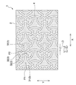
- FIG. 1 is a plan view showing the cleaning surface side of the wet cleaning sheet according to the first embodiment of the present invention.
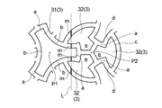
- FIG. 2 is an enlarged plan view showing a part of the uneven pattern of the base sheet of the wet cleaning sheet shown in FIG.
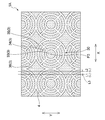
- FIG. 3 is a plan view (corresponding to FIG. 1) showing the cleaning surface side of the wet cleaning sheet according to the second embodiment of the present invention.
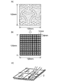
- FIG. 4A to FIG. 4C are explanatory diagrams of an evaluation method for the degree of variation in the degree of entanglement.
- FIG. 5 is a plan view showing an example of a mesh sheet forming a part of the base sheet.
- FIG. 6 is a perspective view showing an example of a cleaning tool with a handle.
- FIG. 1 is a plan view showing the cleaning surface side of the wet cleaning sheet according to the first embodiment of the present invention.
- FIG. 2 is an enlarged plan view showing a part of the uneven pattern of the base sheet of the wet cleaning sheet shown in FIG.
- FIG. 3
- FIG. 7 is an explanatory view showing an outline of a preferred method for producing the wet cleaning sheet of the present invention.
- FIG. 8 is a schematic diagram showing a rotating drum provided in the water needling apparatus shown in FIG. 7 and the vicinity thereof.
- FIG. 9 is a perspective view showing an example of a pattern forming net preferably used for manufacturing the wet cleaning sheet of the first embodiment.
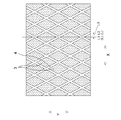
- FIG. 10 is a plan view (corresponding to FIG. 1) showing the cleaning surface side of the wet cleaning sheet of Comparative Example 1.
- the present invention relates to a wet cleaning sheet with improved hair capture performance.
- the wet cleaning sheet 1 includes a base sheet 2 and a cleaning liquid (not shown) carried on the base sheet 2.
- FIG. 1 shows the cleaning surface side of the wet cleaning sheet 1, that is, the side directed to the object to be cleaned when cleaning is performed. And as shown in FIG. 1, it has the unevenness
- the concave portion 4 and the convex portion 3 are formed on the cleaning surface side of the base sheet 2, and the boundary line between the convex portion 3 and the concave portion 4 has a curved portion when viewed macroscopically.
- the curvilinear shape means a concavo-convex pattern excluding a curve constituting a micro-to-nanoscale fine hole and a curve constituting a drain hole having a diameter of about 1.5 to 2 mm. This means that part of the side of the figure to be curved is a curve.
- the concavo-convex pattern of the base sheet 2 in the wet cleaning sheet 1 of the first embodiment will be described.
- the concavo-convex pattern of the base sheet 2 includes a plurality of convex portions 3 separated by the concave portions 4 and the concave portions 4 in the planar direction. Each of the convex portions 3 is surrounded by the concave portion 4.
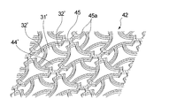
- the plurality of convex portions 3 include a plurality of types of convex portions 31 and 32 having different shapes in plan view. More specifically, as shown in FIG. 2, three first arcs a located on a circle centered on the point P1 and three second arcs protruding in the opposite direction interposed between the first arcs a.
- a substantially triangular first convex portion 31 surrounded by b, one arc c located on a circle centered on the point P2, two arcs d facing the arc c, and between the two arcs d And a second convex part 32 having a substantially pentagonal part e projecting in the direction of the point P2.
- Three second convex portions 32 are arranged at equal intervals around the common one P2, and adjacent second convex portions 32 among the three second convex portions 32 arranged at equal intervals. , 32, the first arc a portion of the first convex portion 31 is inserted.
- first convex portion 31 and the second convex portion 32 are based on the distance from the point P1 to the first arc a (the radius of a circle having three first arcs a centered on the point P1) and the point P2.
- the distance to the arc c (the radius of the circle having the arc c centered on the point P2) is the same.
- the point P1 is located outside the circle having the arc c centered on the point P2, and the point P2 is located outside the circle having three first arcs a centered on the point P1.
- the uneven pattern shown in FIG. 1 of the first embodiment satisfies the following three conditions (1) to (3).
- the base material sheet in this invention has the 1st direction X which is the flow direction at the time of manufacture, and the 2nd direction Y orthogonal to the 1st direction X.
- the flow direction at the time of manufacture is synonymous with the machine direction MD at the time of manufacture (see FIG. 7).
- the flow direction during production usually coincides with the main orientation direction of the constituent fibers. Therefore, the main orientation direction of the constituent fibers can be the first direction X in both cases where the flow direction during production is clear and where the flow direction during production is unknown.
- the “main orientation direction of the constituent fibers” is the constituent fiber of the major axis direction along the long side of the rectangle and the minor axis direction along the short side of the rectangle.
- the degree of orientation is higher.
- the second direction Y is a direction orthogonal to the first direction X, and when the first direction X is the flow direction during manufacture of the base sheet (same as the machine direction MD during manufacture), the flow When the first direction X is the main orientation direction of the constituent fibers, it is a direction orthogonal to the first direction (CD).
- the length of the uneven boundary line per 1 cm 2 is 10 mm or more.
- the concavo-convex boundary line is a boundary line between the convex portion 3 and the concave portion 4, and is set to the rising base end portion of the convex portion 3 from the concave portion 4 in the thickness direction of the base sheet 2.
- the length of the uneven boundary line per 1 cm 2 (hereinafter also referred to as “boundary circumference”) is measured by the following method.
- the total length of the uneven boundary line in the rectangular region (hereinafter also referred to as a measurement target region) having a length in the first direction X of 280 mm and a length in the second direction Y of 200 mm is divided by the area of the region.
- the value is the boundary circumference.
- the measurement target region is determined so that the center points in the first direction and the second direction in the wet cleaning sheet to be measured coincide with the center points in the first direction and the second direction of the measurement target region.
- the boundary circumferential length is relatively short when the planar view shape of the uneven boundary line is relatively simple, and is relatively long when there are many inflection points on the sides of the planar view shape of the uneven boundary line. Therefore, the value of the boundary circumference is an index indicating the complexity of the planar view shape of the uneven boundary line.
- the boundary perimeter is 10 mm or more, the site
- the boundary circumference is at least 10 mm or more, preferably 11 mm or more. Further, it is preferably 50 mm or less, more preferably 30 mm or less, and preferably 10 mm or more and 50 mm or less, more preferably 11 mm or more and 30 mm or less.
- each convex portion 3 surrounded by the concave portion 4 is 300 mm 2 or more.
- the area of each convex part 3 completely surrounded by the concave part 4 is the area of each convex part, and each is 300 mm 2 or more.
- the area of all or most convex parts is 300 mm ⁇ 2 > or more.
- the majority of the area being 300 mm 2 or more means that 80% or more of the convex portions 3 that are present in the measurement target region and are completely surrounded by the concave portions 4 on the basis of the number. Means an area of 300 mm 2 or more.
- the area of all the convex parts is 300 mm ⁇ 2 > or more.
- the maximum value of the area of the convex portion 3 surrounded by the concave portion 4 is preferably 3000 mm 2 or less, more preferably 2000 mm 2 or less.
- each protrusion 3 is measured by the following method.
- a small convex portion corresponding to the drain hole 45a may be formed.
- the “convex portions” of the convex portions and concave portions forming the concave / convex pattern of the present invention do not include such small convex portions.
- first straight lines L1 having the maximum total length of the portion m overlapping the concave portion of the concave / convex pattern in the first direction X, or the second length having the minimum total length of the portion m overlapping the concave portion of the concave / convex pattern.
- first straight line L1 and the second straight line L2 that minimize the distance between the straight lines are selected, and the distance between the two straight lines is selected.
- the shortest distance is the minimum distance L3 in the first direction X.
- the unevenness change index is preferably 10 or more, more preferably 15 or more, and still more preferably 20 or more.
- the unevenness change index is preferably 50 or less, more preferably 45 or less, preferably 10 or more and 50 or less, more preferably 15 or more and 45 or less, and further preferably 20 or more and 40 or less.
- the reason why the hair capturing performance is enhanced when the unevenness change index is high is equivalent to the length of the water flow entanglement process at the time of manufacture in which the water flow is blocked by the pattern forming net (the length of the portion m overlapping the concave portion 4 of the uneven pattern) ) Changes abruptly, that is, the higher the change index of the unevenness, the more likely the variation in the degree of entanglement of the constituent fibers of the fiber assembly occurs.
- a portion m of the straight line L extending in the second direction Y that overlaps the concave portion 4 of the concave-convex pattern is shown in FIG.
- a thick line portion is a portion m that overlaps the concave portion 4 of the concave-convex pattern.
- the total length of the portion m that overlaps the concave portion 4 of the concavo-convex pattern is the total value of the length of the portion m that overlaps the concave portion 4 in 200 mm that is the total length in the second direction Y in the measurement target region.
- the uneven pattern formed on the cleaning surface side of the base sheet 2 satisfies the three conditions (1) to (3), thereby performing wet cleaning.
- it In addition to removing small dust such as sand dust, it also has excellent hair capture performance.
- FIG. 3 is a plan view showing an uneven pattern of unevenness formed on the cleaning surface side of the base sheet 2 of the wet cleaning sheet 1A of the second embodiment.
- corrugated pattern of the base material sheet 2 of 2nd Embodiment also has a macroscopic curve part. Moreover, it has the some convex part 3 isolate
- the plurality of convex portions 3 a plurality of types of convex portions 33 to 36 having different shapes in plan view are provided. More specifically, as shown in FIG.
- the sixth convex portion 36 is formed so as to be surrounded by the four circular convex portion groups 30.
- the sixth convex portion 36 has a deformed square shape in which the four sides of the square are replaced with a concave arc shape toward the outside.
- the uneven pattern formed on the cleaning surface side of the base sheet 2 satisfies the three conditions (1) to (3), whereby the wet cleaning sheet 1A is wet.
- the first straight line L ⁇ b> 1 having the maximum total length of the portion m overlapping the concave portion 4 of the concave / convex pattern and the portion m overlapping the concave portion 4 of the concave / convex pattern are illustrated.
- the minimum distance L3 in the first direction X between the second straight line L2 having the minimum total length and the first straight line L1 and the second straight line L2 is shown.
- the fiber entanglement degree in the sheet surface is non-uniform from the viewpoint of improving hair capture performance, and the variation of the entanglement degree is not uniform.
- the 120 mm square area of the sheet surface (cleaning surface) is divided into 12 mm square block-shaped small areas, and tapes are applied to each small area.
- the standard deviation of the amount of fibers coming out from each small region when the tripping method test is performed is preferably 0.6 mg or more, and more preferably 0.65 mg or more.
- the standard deviation is preferably 0.8 mg or less, more preferably 0.7 mg or less, and preferably 0.6 mg or more and 0.8 mg or less, more preferably 0.65 mg or more and 0.7 mg or less.
- the total amount of fibers that have fallen out of the 120 mm square region is preferably 100 mg to 200 mg, more preferably 120 mg to 170 mg.
- the tape stripping method test was performed according to the following procedure using a base sheet before supporting the cleaning liquid. That is, a 12 mm wide Tepla (registered trademark) standard tape (manufactured by King Jim Co., Ltd.) was cut at 12 mm intervals to obtain a 12 mm square seal, which was placed in a 120 mm square area as shown in FIG. The tweezers were used to arrange them without gaps on the set 100 small regions. Then, a load of 10 g was placed on the 100 seals, and a load of 10 g was applied per 12 mm square. It was allowed to stand for 24 hours in an environment of 20 ° C., and after 24 hours, each seal was peeled off, and the amount of adhered fibers was measured for each seal.
- Tepla registered trademark
- the base sheet 2 of the wet cleaning sheets 1 and 1A according to the first and second embodiments has a fiber assembly on both surfaces of a net 11 as a mesh sheet, the constituent fibers are intertwined, and the constituent fibers are It has a configuration integrated with the mesh sheet in an intertwined state.
- the net-like sheet constituting the base sheet 2 is a broad concept including a perforated film having a large number of holes.
- a perforated film having many holes for example, in addition to the net 11 as shown in FIG. 5, the holes as shown in FIG. And a perforated film having many holes as shown in FIG. 8 of Patent Document 1.
- the net 11 as the net-like sheet a net formed as a whole is used, but the shape of the holes formed in the net 11 can be variously modified.
- the fiber assembly constituting both surfaces or one surface of the base sheet 2 is composed of entangled fibers.
- constituent fibers of the fiber assembly include thermoplastic fibers such as polyesters, polyamides, and polyolefins, or composite fibers thereof, split fibers, or ultrafine fibers manufactured by the melt blown method, semi-synthetic materials such as acetate, etc. Any of fibers, recycled fibers such as cupra and rayon, and natural fibers such as cotton (cotton) may be used. It is preferable to use a heat-shrinkable net as the net-like sheet. When the heat-shrinkable net is used, the heat-shrinkable net is subjected to heat shrinkage due to heat treatment when the cleaning sheets 1 and 1A are manufactured.
- heat-shrinkable nets include polyolefins such as polyethylene, polypropylene and polybutene, polyesters such as polyethylene terephthalate and polybutylene terephthalate, polyamides such as nylon 6 and nylon 66, acrylonitriles and vinyls.
- a net that is uniaxially or biaxially shrunk, or a woven or knitted net using a filament that is thermally shrunk with the thermoplastic polymer as at least one of warp or weft, is preferable.
- the wire diameter is preferably 20 ⁇ m to 500 ⁇ m, more preferably 100 ⁇ m to 200 ⁇ m, and the distance between the lines is preferably 2 mm to 30 mm, more preferably 4 mm to 20 mm.
- the base material sheet 2 is one in which fiber aggregates are arranged on both sides of the mesh sheet, the fiber aggregates on both sides of the mesh sheet may be the same or different.
- the base material sheet 2 may be one in which the fiber aggregate is arranged on only one side instead of the one having the fiber aggregate on both sides of the net-like sheet.
- the wet cleaning sheet of the present invention is obtained by supporting a cleaning liquid on the fiber assembly of the base sheet 2.
- the cleaning liquid is preferably an aqueous solution containing at least one of a surfactant, a solvent, and an alkali agent.
- the surfactant examples include various active agents such as nonionic, cationic, anionic, and amphoteric.
- anionic surfactant a normal sulfonate anionic surfactant or a sulfate anionic surfactant is used.
- sulfonate anionic surfactants include linear or branched alkyl (C 8 to C 22 ) benzene sulfonate, long chain alkyl (C 8 to C 22 ) sulfonate, and long chain olefin (C 8 to C 22 ) sulfonate and the like.
- sulfate anionic surfactants include long-chain monoalkyl (C 8 -C 22 ) sulfate esters, polyoxyethylene (1-6 mol) long-chain alkyl (C 8 -C 22 ) ether sulfates. Salt, polyoxyethylene (1 to 6 mol) alkyl (C 8 to C 18 ) phenyl ether sulfate salt, and the like.
- Cations as counter ions of these anionic surfactants are alkali metal ions such as sodium and potassium, alkanolamine ions such as monoethanolamine, diethanolamine and triethanolamine. From the viewpoint of strong resistance to hydrolysis, the anionic surfactant is preferably a sulfonate surfactant.
- a long chain or branched alkylbenzene sulfonate is preferred from the viewpoint of detergency.
- amphoteric surfactant include carbobetaine, sulfobetaine and hydroxysulfobetaine having an alkyl group having 8 to 22 carbon atoms.
- nonionic surfactant include polyoxyethylene (6-35 mol) long-chain alkyl or alkenyl (primary or secondary (C 8 -C 22 ) ether, polyoxyethylene (6-35).
- Polyethylene glycol ether type such as alkyl (C 8 -C 18 ) phenyl ether, polyoxyethylene polyoxypropylene block copolymer, or polyhydric alcohol type such as glycerin fatty acid ester, sorbitan fatty acid ester, alkyl glycoside and the like.
- the cationic surfactant include mono long-chain alkyltrimethylammonium salts having a C10-22 alkyl group or alkenyl group, long-chain alkyldimethylammonium salts, monolong-chain alkyldimethylbenzylammonium salts, and the like.
- the solvent examples include alcohols such as ethanol and isopropanol, glycols such as ethylene glycol and propylene glycol, and glycol ethers such as ethylene glycol monoethyl ether and propylene glycol monomethyl ether.
- the agent examples include alkanolamines such as monoethanolamine.
- the cleaning liquid may contain components such as a bactericide, a deodorant, and a fragrance as necessary.
- the amount of the cleaning liquid supported is preferably 300% or more, more preferably 400% or more, and preferably 800% or less, more preferably, based on the total mass of the fiber aggregate contained in the base sheet. It is 500% or less, preferably 300% or more and 800% or less, more preferably 400% or more and 500% or less.
- the above-described wet cleaning sheets such as the wet cleaning sheets 1 and 1A can be used by being attached to a cleaning tool with a handle in addition to directly cleaning the sheet by operating the hand. It is preferable to use it attached to a cleaning tool with a handle from the viewpoint of easily performing a cleaning operation.
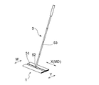
- a cleaning tool with a handle for example, as shown in FIG. 6, a head portion 51 to which a wet cleaning sheet can be attached, and a rod-like handle 53 connected to the head portion 51 via a universal joint 52.
- the cleaning tool 5 with the handle comprised from these is mentioned.
- the sheet mounting surface of the head portion 51 can be rectangular, for example, in plan view, and in a normal use mode, the handle cleaning tool 5 moves the head portion 51 in the direction along the short side direction. (Especially reciprocating) to clean. That is, the direction along the short side direction of the head portion 51 is the main moving direction M when cleaning with the handle cleaning tool 5, and the wet cleaning sheet of the present invention is the flow direction during manufacture or the main orientation of the constituent fibers. It is preferable to use the second direction Y perpendicular to the first direction X, which is the direction, in accordance with the main movement direction M because the hair collection performance is further improved.
- the wet cleaning sheet of the present invention is a wet cleaning sheet that is used by being mounted on the head portion of the cleaning tool with a handle, the cleaning surface of which has a rectangular head portion in plan view. It is used that the two directions Y coincide with the direction M along the short side of the head part 51 and the first direction X coincides with the direction along the long side of the head part 51. It is preferable from the viewpoint of exhibiting excellent collection performance.
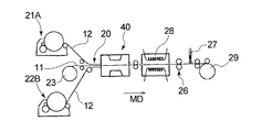
- the fiber aggregate 12 is manufactured by the card machines 21 ⁇ / b> A and 21 ⁇ / b> B, and is joined to the top and bottom of the mesh sheet 11 fed out from the raw roll 23, and has a fiber aggregate 12 on both surfaces of the mesh sheet 11.
- a laminated body 20 is formed and introduced into the water needling apparatus 40.
- the fiber assembly 12 is preferably a fiber assembly formed from a fiber web. As shown in FIG.
- the water needling device 40 includes a rotary drum 41 as a water permeable support member including a plurality of spring coils 41 b whose outer peripheral portion 41 a extends in the rotation axis direction, and an outer peripheral portion 41 a of the rotary drum 41.
- a pattern forming net 42 disposed on the rotating drum 41 and a jet water jetting device 43 that jets a jet water flow from the outside to the inside of the rotary drum 41.
- the pattern forming net 42 shown in FIG. 9 forms the concave / convex pattern shown in FIG. 1, and has openings similar to the first convex portion 31 and the second convex portion 32 in the concave / convex pattern shown in FIG.
- the pattern forming net 42 is made of a water-resistant material such as metal or synthetic resin. As shown in FIG. 9, the pattern forming net 42 has a large number of drain holes 45 a having a diameter smaller than the width of the band-like part 45 in the band-like part 45, and water splashes due to the jet water stream hitting the band-like part 45. Can be prevented or reduced.
- the openings 31 ′ and 32 ′ of the pattern forming net 42 may be formed by punching, but are preferably formed by laser processing because the pattern forming net 42 is less likely to be distorted.
- the drain hole 45a is preferably formed by a punching process such as a punching process from the viewpoint of preventing burrs from occurring at the peripheral edge of the opening.
- a punching process such as a punching process from the viewpoint of preventing burrs from occurring at the peripheral edge of the opening.
- the constituent fibers of the fiber assembly 12 made of the fiber web on one side of the mesh sheet 11 and the fiber assembly 12 made of the fiber web on the other side are entangled.
- the non-woven fiber assembly, the fibers of the fiber assembly 12 on one side and the fibers of the fiber assembly 12 on the other side, and the fibers of the fiber assembly 12 and the mesh sheet 11 are also entangled.
- the base material sheet 2 in which the concavo-convex pattern shown in FIG. 1 is formed is obtained.
- the base material sheet 2 is carried in the heating apparatus 28, and is heat-processed.
- the base sheet 2 is dried, and when a heat-shrinkable net-like sheet is used as the net-like sheet 11, the net-like sheet is heat-shrinked and formed in a hydroentanglement process using a water needling device. Minute unevenness is formed on the surface of each protrusion.
- the cleaning liquid is carried on the base sheet 2 after the heat treatment.
- the method for supporting the cleaning liquid on the base sheet 2 is not particularly limited. For example, as shown in FIG. 7, the cleaning liquid is applied by a spray device 27 disposed between a nip roll 26 and a winder 29. .
- the application of the cleaning liquid can be performed before the heat treatment instead of being performed after the heat treatment on the base sheet 2.
- the wet cleaning sheet obtained by supporting the cleaning liquid may be wound into a roll, cut into a required length, and further folded and wrapped as necessary. Good. In this way, the wet cleaning sheet of the present invention can be obtained efficiently.
- the length at which the water flow is blocked by the pattern forming net changes rapidly.
- the base sheet and the wet cleaning sheet having a large variation in the degree of entanglement of the fibers of the fiber assembly in the planar direction of the sheet can be obtained.
- the first direction X of the wet cleaning sheet coincides with the moving direction (machine direction MD) of the belt-like laminate 20 when the jet water flow is blown in the water entangling step.
- the unevenness on the cleaning surface side of the wet cleaning sheet of the present invention is such that the height difference between the top of the projection 3 and the bottom of the recess 4 is preferably 0.5 mm or more, more preferably 1.2 mm or more. Is from 0.5 mm to 5 mm, more preferably from 1 mm to 2.5 mm. The height difference is obtained by observing the cut end surface under no load.
- the basis weight of the fiber assembly part is preferably 50 g / m 2 or more, more preferably 65 g / m 2 or more, preferably 100 g / m 2 or less, more preferably.
- the fiber aggregate is supported by the base sheet, in which the constituent fibers are intertwined with each other and the constituent fibers are intertwined with the net-like sheet.
- the substrate sheet has a concavo-convex pattern with a macroscopic curved portion on the cleaning surface side, and the concavo-convex pattern has a concavo-convex boundary line length of 10 mm or more per 1 cm 2.
- each convex part surrounded by the concave part is 300 mm 2 or more, and has a first direction which is a flow direction at the time of production or a main orientation direction of constituent fibers and a second direction orthogonal to the first direction.
- the total length of the portions overlapping the concave portions of the concave-convex pattern Is the total length of the largest straight line
- the value obtained by dividing the difference between the total length of the minimum straight lines having the minimum total length of the portions overlapping the concave portions of the concave / convex pattern by the minimum distance in the first direction between the maximum straight lines and the minimum straight lines is 10 or more.
- the concavo-convex pattern has a plurality of the convex portions separated by the concave portions and the concave portions in a planar direction, and each of the convex portions is surrounded by the concave portions.
- corrugated pattern is a sheet
- the concavo-convex pattern includes, as the plurality of convex portions, three first circular arcs a that are located on a circle centered on the point P1 and three second circular arcs that are convex in opposite directions interposed between the first circular arcs a. a substantially triangular first convex portion surrounded by b, one arc c located on a circle centered on the point P2, two arcs d facing the arc c, and between the two arcs d.
- the wet cleaning sheet according to any one of ⁇ 1> to ⁇ 3>, further including a second convex portion having a substantially pentagonal portion e projecting in the direction of the point P2.
- the first convex portion and the second convex portion have the same length as the radius of the circle centered on the point P1 and the radius of the circle centered on the point P2. Wet cleaning sheet.
- the point P1 is located outside the circle having the arc c centered on the point P2, and the point P2 is located outside the circle having three first arcs a centered on the point P1.
- Three of the second convex portions are arranged at equal intervals in the circumferential direction around the point P2, and each of the adjacent second convex portions among the three second convex portions arranged at equal intervals is arranged.
- the concavo-convex pattern includes, as a plurality of convex portions, a circular third convex portion centered on the point P3, four arc-shaped fourth convex portions arranged to surround the third convex portion, and further Four circular convex fifth convex portions arranged on the outside, and a circular convex group consisting of these convex portions are arranged so as to form a row in each of the first direction and the second direction.
- ⁇ 9> The wet cleaning sheet according to ⁇ 8>, wherein a sixth convex portion is formed in a state surrounded by the four circular convex portion groups.
- the sixth convex portion is the wet cleaning sheet according to ⁇ 9>, wherein the sixth convex portion has a deformed square shape in which four sides of the square are replaced with a concave arc shape toward the outside.
- the boundary circumferential length between the convex part and the concave part is at least 10 mm or more, preferably 11 mm or more, preferably 50 mm or less, more preferably 30 mm or less, and preferably 10 mm or more and 50 mm or less, more preferably.
- ⁇ 12> The wet cleaning sheet according to any one of ⁇ 1> to ⁇ 11>, wherein a small convex portion corresponding to a drain hole is formed in the concave portion.
- ⁇ 14> The total length of the first straight line having the maximum total length of the portion overlapping the concave portion of the concave / convex pattern and the total length of the second straight line having the minimum total length of the portion overlapping the concave portion of the concave / convex pattern.
- the value obtained by dividing the difference by the minimum distance in the first direction between the first straight line and the second straight line is preferably 50 or less, more preferably 45 or less, in the above ⁇ 1> to ⁇ 13>
- the wet cleaning sheet according to any one of the above. ⁇ 15> The wet cleaning sheet according to ⁇ 13> or ⁇ 14>, wherein the value is preferably 10 or more and 50 or less, more preferably 15 or more and 45 or less, and still more preferably 20 or more and 40 or less.
- ⁇ 16> The wet cleaning sheet according to any one of ⁇ 1> to ⁇ 15>, wherein the reticulated sheet includes a reticulated web composed of latent crimp-expressing fiber aggregates in which holes are formed.
- the mesh sheet includes a perforated film having a large number of holes.
- the base sheet has a non-uniform degree of fiber entanglement in the sheet surface, and the 120 mm square region of the sheet surface is divided into 12 mm square block-like small regions, and a tape stripping method is applied to each small region.
- ⁇ 22> The wet cleaning sheet according to any one of ⁇ 1> to ⁇ 19>, wherein the wet cleaning sheet is used by being attached to a cleaning tool with a handle.
- the cleaning surface is a wet cleaning sheet to be used by being mounted on the head portion of the cleaning tool with a handle having a rectangular head portion in plan view, and the second direction is the short side of the cleaning surface of the head portion.
- ⁇ 26> The wet cleaning sheet according to any one of ⁇ 1> to ⁇ 25>, wherein the uneven pattern has an area of 300 mm 2 or more of all or most of the individual protrusions surrounded by the recesses.
- a jet water stream is sprayed on the band-shaped laminate that is introduced into the water-permeable support member and moves together with the water-permeable support member, and a recess having a shape corresponding to the band-shaped portion of the pattern-forming net and an opening of the pattern-forming net are formed on the band-shaped laminate.
- seat for wet cleaning which comprises the hydroentanglement process which forms the convex part of the shape corresponding to 1 and obtains the said base material sheet.
- Example 1 Using the pattern forming net shown in FIG. 9, by the manufacturing method described above, the substrate sheet having the uneven pattern of the uneven pattern shown in FIG. 1 is manufactured on the cleaning surface side. The cleaning liquid was supported in an amount of 350% by mass with respect to the total mass of the fiber aggregate of each base sheet, and the wet cleaning sheet of Example 1 was obtained. The following reticulated sheet and fiber assembly were used for the production of the base sheet.
- Reticulated sheet polypropylene net having the shape shown in FIG. 5 with a wire diameter (fiber diameter) of 200 ⁇ m and a distance between lines of 10 mm.
- Fiber assembly PET (wire diameter 11.5 ⁇ m), acrylic (wire diameter 10.5 ⁇ m), rayon (wire) Card web having short fibers having a diameter of 12 ⁇ m as a constituent fiber
- Cleaning liquid Cleaning liquid containing 0.1% or more of a cleaning base, 1% or more of alcohol, and 50% or more of purified water
- Example 2 The wet cleaning of Example 2 is performed in the same manner as in Example 1 except that the pattern forming net used is changed and the uneven pattern formed on the cleaning surface side of the base sheet is changed to the pattern shown in FIG. A sheet was obtained.
- Comparative Example 1 The wet cleaning of Comparative Example 1 was performed in the same manner as in Example 1 except that the pattern forming net used was changed and the uneven pattern formed on the cleaning surface side of the base sheet was changed to the pattern shown in FIG. A sheet was obtained.
- Comparative Example 2 A wet cleaning sheet of Comparative Example 2 was obtained in the same manner as in Example 1 except that a rotating drum that did not use a pattern forming net was used as the rotating drum of the water needling apparatus.
- the boundary perimeter described above the area of the smallest of the convex portions surrounded by the concave portion and the irregularity change index, It is shown in Table 1.
- the area of the first protrusion 31 was 1192 mm 2
- the area of the second protrusion 32 was 712 mm 2
- the second protrusion 32 was the protrusion having the smallest area.
- test dust JIS Z8901
- test dust JIS Z8901
- each wet cleaning sheet was attached to the head part 51 of the cleaning tool 5 with a handle shown in FIG. 6, and a portion in which 7 kinds of test dust were dispersed was reciprocated 10 times in the short side direction (M direction in the figure).
- the total mass of dust adsorbed on the wet cleaning sheet was measured, and the ratio (%) to 1 g of the dispersed dust was shown in Table 1 as the collection rate (%) of small dust.
- the wet cleaning sheets of Examples 1 and 2 are equivalent to the wet cleaning sheets of Comparative Examples 1 and 2 and exhibit good collection performance. It was. On the other hand, regarding the hair collection performance, the wet cleaning sheets of Examples 1 and 2 clearly improved the collection performance of the wet cleaning sheets of Comparative Examples 1 and 2.
- the base sheet of the wet cleaning sheet of Examples 1 and 2 has a higher standard deviation indicating the variation in the degree of entanglement of the fibers than that of Comparative Example 1, and is compared with that of Comparative Example 1. Thus, the degree of variation in the degree of entanglement of the fibers was large.
- the wet cleaning sheet of the present invention can remove small dust such as dust by wet cleaning, and is excellent in hair capturing performance. According to the method for manufacturing a wet cleaning sheet of the present invention, such a wet cleaning sheet can be efficiently manufactured.
Landscapes
- Engineering & Computer Science (AREA)
- Mechanical Engineering (AREA)
- Textile Engineering (AREA)
- Cleaning Implements For Floors, Carpets, Furniture, Walls, And The Like (AREA)
- Nonwoven Fabrics (AREA)
- Laminated Bodies (AREA)
Abstract
網状シートの片面又は両面に、繊維集合体が、構成繊維どうしが絡合し且つ該構成繊維が網状シートとも絡合した状態で一体化している基材シートと洗浄液とを有し、基材シートは、清掃面側に巨視的な曲線部を有する凹凸パターンの凹凸を有し、凹凸パターンは1cm2あたりの凹凸境界線の長さが10mm以上、凹部(4)で囲まれた個々の凸部(3)の面積が300mm2以上であり、製造時の流れ方向又は繊維の配向方向である第1方向(X)の長さが280mm、第1方向と直交する第2方向(Y)の長さが200mmの長方形状の領域内に、第2方向(Y)に延びる直線(L)を想定したとき、凹部(4)と重なる部分の合計長さが最大の最大直線(L1)の該合計長さと、合計長さが最小の最小直線(L2)の該合計長さとの差を、最大直線(L1)と最小直線(L2)との間の最小距離(L3)で除した値が10以上である。
Description
本発明は、湿式清掃用シートに関する。
水流交絡法により凹凸を形成した清掃用シートが種々提案されている。特許文献1には、水流交絡時にパターン形成用プレートを用いて不織布に特定のパターンの凹凸を形成することが記載されている。
また、本出願人は先に、不織布を利用した湿式清掃用シートとして、網状シートの片面若しくは両面に、繊維ウエブの繊維の絡合で形成された不織布状の繊維集合体がその構成繊維間の絡合と共に該網状シートに対しても絡合状態で一体化されており、且つ上記繊維集合体には該繊維集合体の繊維が波状に隆起配列してその表面に多数の凹凸が形成されている清掃用シートに、洗浄剤を含有する薬剤を坦持させてなる湿式清掃用シートを提案している(特許文献2参照)。
また、本出願人は先に、不織布を利用した湿式清掃用シートとして、網状シートの片面若しくは両面に、繊維ウエブの繊維の絡合で形成された不織布状の繊維集合体がその構成繊維間の絡合と共に該網状シートに対しても絡合状態で一体化されており、且つ上記繊維集合体には該繊維集合体の繊維が波状に隆起配列してその表面に多数の凹凸が形成されている清掃用シートに、洗浄剤を含有する薬剤を坦持させてなる湿式清掃用シートを提案している(特許文献2参照)。
湿式清掃用シートによれば、小さなダストから、パンくず等の比較的大きなダストまで、広い範囲のダストを捕集可能である。
しかし、洗浄液を含む湿式清掃用シートは、ドライタイプの乾式清掃用シートに比較すると髪の毛の捕捉性能が低く、前述した特許文献1に記載の湿式清掃用シートにおいても、髪の毛を100%捕捉できるものではなく、髪の毛の捕捉性能の向上が望まれる。
しかし、洗浄液を含む湿式清掃用シートは、ドライタイプの乾式清掃用シートに比較すると髪の毛の捕捉性能が低く、前述した特許文献1に記載の湿式清掃用シートにおいても、髪の毛を100%捕捉できるものではなく、髪の毛の捕捉性能の向上が望まれる。
本発明は、網状シートの片面又は両面に、繊維集合体が、構成繊維どうしが絡合し且つ該構成繊維が網状シートとも絡合した状態で一体化している基材シートと、該基材シートに担持された洗浄液とを有する湿式清掃用シートを提供するものである。前記基材シートは、清掃面側に、巨視的な曲線部を有する凹凸パターンの凹凸を有している。前記凹凸パターンは、1cm2あたりの凹凸境界線の長さが10mm以上で、凹部で囲まれた個々の凸部の面積が300mm2以上である。また前記基材シートは、製造時の流れ方向又は構成繊維の主たる配向方向である第1方向、及び第1方向に直交する第2方向を有し、第1方向の長さが280mm、第2方向の長さが200mmの長方形状の領域内に、第2方向に延びる直線を想定したときに、前記凹凸パターンの凹部と重なる部分の合計長さが最大の最大直線の該合計長さと、前記凹凸パターンの凹部と重なる部分の合計長さが最小の最小直線の該合計長さとの差を、最大直線と最小直線との第1方向の最小距離で除した値が10以上である。
また本発明は、前記の湿式清掃用シートの製造方法を提供するものである。前記湿式清掃用シートの製造方法は、前記網状シートの片面又は両面に繊維集合体を有する帯状積層体を、平面視曲線状の帯状部を含むパターン形成用ネットを配した透水性支持部材上に導入し、該透水性支持部材とともに移動する帯状積層体に対してジェット水流を吹き付け、該帯状積層体に、パターン形成用ネットの帯状部に対応する形状の凹部及びパターン形成用ネットの開口部に対応する形状の凸部を形成して前記の基材シートを得る水流交絡工程を具備する。
本発明は、髪の毛の捕捉性能が向上した湿式清掃用シートに関するものである。
以下本発明を、その好ましい実施形態に基づき図面を参照しながら説明する。
第1実施形態の湿式清掃用シート1は、基材シート2と、該基材シート2に担持された洗浄液(図示せず)とを有する。図1には、湿式清掃用シート1の清掃面側、即ち清掃を行う際に清掃対象物に向けられる側が示されている。
そして、湿式清掃用シート1の基材シート2の清掃面側に、図1に示すように、巨視的な曲線部を有する凹凸パターンの凹凸を有している。即ち、基材シート2の清掃面側には、凹部4と凸部3とが形成されており、凸部3と凹部4との境界線が、巨視的に見て曲線状の部分を有している。ここで、巨視的に見て曲線状とは、マイクロ~ナノスケールの微細な孔を構成する曲線や、直径1.5~2mm程度の水抜き用穴を構成する曲線を除く、凹凸パターンを構成する図形の辺の一部が曲線であることを意味する。
第1実施形態の湿式清掃用シート1における基材シート2の凹凸パターンについて説明すると、基材シート2の凹凸パターンは、平面方向に、凹部4と凹部4によって分離された複数の凸部3を有し、個々の凸部3は、周囲を凹部4に囲まれている。また、複数の凸部3として、相互に平面視形状が異なる複数種類の凸部31,32を有している。より詳細には、図2に示すように、点P1を中心とする円上に位置する3つの第1円弧aと、第1円弧aどうし間に介在する逆向きに凸の3つの第2円弧bとに囲まれた略三角形状の第1凸部31と、点P2を中心とする円上に位置する一つの円弧cと該円弧cに対向する2つの円弧dと該2つの円弧d間から点P2方向に突出する略五角形部分eとを有する第2凸部32とを有している。第2凸部32は、共通する一つのP2を中心として、その周囲に等間隔に3つ配置され、等間隔に配置された3つの第2凸部32のうちの隣り合う第2凸部32,32間のそれぞれに、第1凸部31の第1円弧a部分が入り込んでいる。
また、第1凸部31と第2凸部32とは、点P1から第1円弧aまでの距離(点P1を中心とした3つの第1円弧aを有する円の半径)と、点P2から円弧cまでの距離(点P2を中心とした円弧cを有する円の半径)とは同じである。また、点P1は、点P2を中心とした円弧cを有する円の外側に位置し、点P2は、点P1を中心とした3つの第1円弧aを有する円の外側に位置している。
第1実施形態の図1に示す凹凸パターンは、下記(1)~(3)の3条件を満たしている。
なお、本発明における基材シートは、製造時の流れ方向である第1方向X、及び第1方向Xに直交する第2方向Yを有している。製造時の流れ方向は、製造時の機械方向MD(図7参照)と同義である。製造時の流れ方向は、通常、構成繊維の主たる配向方向と一致する。したがって、製造時の流れ方向が明らかな場合、及び製造時の流れ方向が不明の場合のいずれの場合であっても、構成繊維の主たる配向方向を第1方向Xとすることができる。基材シート2の平面視形状が長方形である場合の「構成繊維の主たる配向方向」は、該長方形の長辺に沿う長軸方向と該長方形の短辺に沿う短軸方向のうち、構成繊維が配向している程度が高い方である。
他方、第2方向Yは、第1方向Xに直交する方向であり、第1方向Xが、基材シート製造時の流れ方向(製造時の機械方向MDと同じ)である場合は、該流れ方向に直交する方向(CD)であり、第1方向Xが、構成繊維の主たる配向方向である場合は、当該第1方向に直交する方向である。
(条件1)
凹凸パターンは、1cm2あたりの凹凸境界線の長さが10mm以上である。
ここで、凹凸境界線とは、凸部3と凹部4との境界線であり、基材シート2の厚み方向においては、凸部3の凹部4からの立ち上がり基端部に設定する。
1cm2あたりの凹凸境界線の長さ(以下、「境界周長」ともいう)は、下記方法により測定する。
〔境界周長の測定方法〕
第1方向Xの長さが280mm、第2方向Yの長さが200mmの長方形状の領域(以下、測定対象領域ともいう)内に存する凹凸境界線の総長を、該領域の面積で除した値を境界周長とする。なお、測定対象領域は、測定対象の湿式清掃用シートにおける第1方向及び第2方向の中心点と、該測定対象領域の第1方向及び第2方向の中心点とが一致するように定める。
境界周長は、凹凸境界線の平面視形状が比較的単純な場合は相対的に短く、凹凸境界線の平面視形状の辺々における変曲点が多い場合は相対的に長くなる。従って、境界周長の値は、凹凸境界線の平面視形状の複雑さを示す指標となる。そして、境界周長が10mm以上であることにより、髪の毛の引っ掛るきっかけとなる部位が増加して、湿式清掃時の髪の毛の捕捉性が顕著に向上することになる。
境界周長は、少なくとも10mm以上であり、好ましくは11mm以上である。また好ましくは50mm以下、より好ましくは30mm以下であり、また好ましくは10mm以上50mm以下、より好ましくは11mm以上30mm以下である。
境界周長は、少なくとも10mm以上であり、好ましくは11mm以上である。また好ましくは50mm以下、より好ましくは30mm以下であり、また好ましくは10mm以上50mm以下、より好ましくは11mm以上30mm以下である。
(条件2)
凹凸パターンは、凹部4で囲まれた個々の凸部3の面積が300mm2以上である。凹部4で囲まれた個々の凸部3は、完全に凹部4に囲まれた凸部3のみを選択し、測定対象領域の縁部で切れている凸部は対象外とする。つまり、凹凸パターンの内、完全に凹部4で囲まれた凸部3それぞれの面積が、個々の凸部の面積であり、それぞれ300mm2以上である。
凹部4で囲まれた個々の凸部3は、全部又は大部分の凸部の面積が300mm2以上である。ここで、大部分の面積が300mm2以上であるとは、測定対象領域内に存在する、周囲を完全に凹部4に囲まれた凸部3のうち、個数を基準として80%以上の凸部の面積が300mm2以上であることを意味する。凹部4で囲まれた個々の凸部3は、その全部の凸部の面積が300mm2以上であることが一層好ましい。凹部4で囲まれたの凸部3の面積の最大値は、好ましくは3000mm2以下、より好ましくは2000mm2以下である。
面積の大きな凸部3を形成することで、微小な凸部を不織布の全体に亘って形成する場合に比べて、湿式清掃時の髪の毛の捕捉性を向上させることができる。
凹部4で囲まれた個々の凸部3の面積(以下、「個々の凸部の面積」ともいう)は、下記方法により測定する。
〔個々の凸部の面積の測定方法〕
第1方向Xの長さが280mm、第2方向Yの長さが200mmの長方形状の領域(測定対象領域)内に存する凸部のうち、周囲を完全に凹部4で囲まれたもの、即ち輪郭の全体が測定対象領域内に存するものを選択し、選択した凸部の面積の測定値のそれぞれを、個々の凸部3の面積とする。
条件2を満たすためには、選択し、測定した複数の凸部3の面積の測定値のそれぞれが、300mm2以上であることが好ましい。
なお、製造時の水流交絡工程に、図9に示すような、水抜き穴45aを有するパターン形成用ネット42を用いた場合、パターン形成用ネット42の帯状部45に対応する凹部4内に、水抜き穴45aに対応する小凸部が形成されることがある。本発明の凹凸パターンを形成する凸部及び凹部の「凸部」には、このような小凸部は含まれない。
(条件3)
第1方向Xの長さが280mm、第2方向Yの長さが200mmの長方形状の領域(測定対象領域)内に、第2方向Yに延びる直線Lを想定したときに、凹凸パターンの凹部4と重なる部分mの合計長さが最大の第1直線L1の該合計長さLmaxと、凹凸パターンの凹部4と重なる部分mの合計長さが最小の第2直線L2の該合計長さLminとの差(Lmax-Lmin)を、第1直線L1と第2直線L2との間の第1方向Xの最小距離L3で除した値〔(Lmax-Lmin)/L3〕が10以上である。以下、この値〔(Lmax-Lmin)/L3〕を、便宜的に「凹凸変化指数」という。凹凸変化指数は、第2方向Yに延びる直線Lを第1方向Xに連続的に移動させたときに、凹部と重なる部分mの長さが急激に変化する程高くなる。
凹凸パターンの凹部と重なる部分mの合計長さが最大の第1直線L1が、第1方向Xに複数本存在する場合、若しくは凹凸パターンの凹部と重なる部分mの合計長さが最小の第2直線L2が、第1方向に複数本存在する場合、又はそれらの両方である場合には、直線間の間隔が最小となる第1直線L1及び第2直線L2を選択し、その2直線間の最短距離を、第1方向Xの最小距離L3とする。
凹凸変化指数が高いと髪の毛の捕捉性能が高まる。
凹凸変化指数は、10以上であることが好ましく、より好ましくは15以上、更に好ましくは20以上である。また、凹凸変化指数は、好ましくは50以下、より好ましくは45以下であり、また、好ましくは10以上50以下、より好ましくは15以上45以下、更に好ましくは20以上40以下である。
凹凸変化指数が高いと髪の毛の捕捉性能が高まる理由は、製造時の水流交絡工程において、水流がパターン形成用ネットにより遮断される長さ(凹凸パターンの凹部4と重なる部分mの長さに相当)が急激に変化する程、即ちこの凹凸の変化指数が高い程、繊維集合体の構成繊維の交絡の度合いにばらつきが生じるためであると推定される。
凹凸変化指数は、10以上であることが好ましく、より好ましくは15以上、更に好ましくは20以上である。また、凹凸変化指数は、好ましくは50以下、より好ましくは45以下であり、また、好ましくは10以上50以下、より好ましくは15以上45以下、更に好ましくは20以上40以下である。
凹凸変化指数が高いと髪の毛の捕捉性能が高まる理由は、製造時の水流交絡工程において、水流がパターン形成用ネットにより遮断される長さ(凹凸パターンの凹部4と重なる部分mの長さに相当)が急激に変化する程、即ちこの凹凸の変化指数が高い程、繊維集合体の構成繊維の交絡の度合いにばらつきが生じるためであると推定される。
なお、第2方向Yに延びる直線Lの、凹凸パターンの凹部4と重なる部分mを図2に示す。図2に示す各直線L中、太線とした部分が、凹凸パターンの凹部4と重なる部分mである。凹凸パターンの凹部4と重なる部分mの合計長さは、前記測定対象領域における第2方向Yの全長である200mmのうちの凹部4と重なる部分mの長さの合計値である。
第1実施形態の湿式清掃用シート1は、基材シート2の清掃面側に形成された凹凸の凹凸パターンが、前記(1)~(3)の3条件を満たすことによって、湿式清掃により、砂埃等の小さなダストを除去できる上に、髪の毛の捕捉性能にも優れている。
図3は、第2実施形態の湿式清掃用シート1Aの基材シート2の清掃面側に形成された凹凸の凹凸パターンを示す平面図である。
第2実施形態の基材シート2の凹凸パターンも、巨視的な曲線部を有している。また平面方向に、凹部4と凹部4によって分離された複数の凸部3を有し、個々の凸部3は、周囲を凹部4に囲まれている。また、複数の凸部3として、相互に平面視形状が異なる複数種類の凸部33~36を有している。より詳細には、図3に示すように、点P3を中心とする円形の第3凸部33と、第3凸部33を囲むように配された円弧状の4つの第4凸部34と、更にその外側に配された円弧状の4つの第5凸部35とを有し、これらの凸部からなる円形凸部群30が、第1方向X及び第2方向Yにそれぞれ列を形成するように配置され、4つの円形凸部群30に周囲を囲まれた状態に第6凸部36が形成されている。第6凸部36は、正方形の4辺を外方に向かって凹の円弧状に代えた変形正方形状を有している。
第2実施形態の基材シート2の凹凸パターンも、巨視的な曲線部を有している。また平面方向に、凹部4と凹部4によって分離された複数の凸部3を有し、個々の凸部3は、周囲を凹部4に囲まれている。また、複数の凸部3として、相互に平面視形状が異なる複数種類の凸部33~36を有している。より詳細には、図3に示すように、点P3を中心とする円形の第3凸部33と、第3凸部33を囲むように配された円弧状の4つの第4凸部34と、更にその外側に配された円弧状の4つの第5凸部35とを有し、これらの凸部からなる円形凸部群30が、第1方向X及び第2方向Yにそれぞれ列を形成するように配置され、4つの円形凸部群30に周囲を囲まれた状態に第6凸部36が形成されている。第6凸部36は、正方形の4辺を外方に向かって凹の円弧状に代えた変形正方形状を有している。
第2実施形態の湿式清掃用シート1Aも、基材シート2の清掃面側に形成された凹凸の凹凸パターンが、前記(1)~(3)の3条件を満たしており、それによって、湿式清掃により、湿式清掃により、砂埃等の小さなダストを除去できる上に、髪の毛の捕捉性能にも優れている。図3中に、第2実施形態の湿式清掃用シート1Aについての、凹凸パターンの凹部4と重なる部分mの合計長さが最大の第1直線L1と、凹凸パターンの凹部4と重なる部分mの合計長さが最小の第2直線L2及び第1直線L1と第2直線L2との間の第1方向Xの最小距離L3を示した。
第1及び第2実施形態の湿式清掃用シート1,1Aは、髪の毛の捕捉性能の向上の観点から、シート面内における繊維の交絡度合が不均一であることが好ましく、その交絡度合のばらつきの程度は、図4(a)~図4(c)に示すように、シート面(清掃面)の120mm四方の領域を12mm四方のブロック状の小領域に分割し、各小領域に対してテープストリッピング法試験を行ったときの個々の小領域から抜ける繊維量の標準偏差が、0.6mg以上であることが好ましく、より好ましくは0.65mg以上である。また前記標準偏差は、好ましくは0.8mg以下、より好ましくは0.7mg以下であり、また好ましくは0.6mg以上0.8mg以下、より好ましくは0.65mg以上0.7mg以下である。また、120mm四方の領域から抜けた繊維の総量は、好ましくは100mg以上200mg以下、より好ましくは120mg以上170mg以下である。
テープストリッピング法試験は、洗浄液を担持させる前の基材シートを用い、以下の手順で行った。
即ち、幅12mmのテプラ(登録商標)標準テープ(株式会社キングジム製)を12mm間隔に切断して12mm四方のシールを得、それを、図4(b)に示すように、120mm四方の領域に設定した合計100個の小領域上にピンセットを用いて隙間なく並べた。そして、その100枚のシール上に、10gの荷重を載せ12mm四方あたり10gの荷重を加えた。それを20℃の環境下に、24時間放置し、24時間経過後の各シールを剥がし、シール毎に繊維の付着量を測定した。測定は0.1mg単位で測定した。なお、シールは、図4(c)に示すように、斜め下の角部をピンセットに挟み、各シールを対角線に沿って引き剥がした。
100枚のシールのそれぞれに付着した繊維量(質量)の標準偏差を求めた。
第1及び第2実施形態の湿式清掃用シート1,1Aの基材シート2は、網状シートとしてのネット11の両面に、繊維集合体が、その構成繊維どうしが絡合し且つ該構成繊維がその網状シートとも絡合した状態で一体化した構成を有している。
基材シート2を構成する網状シートは、孔を多数有する有孔フィルムを含む広い概念であって、例えば、図5に示すようなネット11の他、特許文献1の図7に示すような孔を形成した潜在捲縮発現繊維集合体からなる網状ウエブ、及び特許文献1の図8に示すような孔を多数有する有孔フィルムを含むものである。網状シートとしてのネット11としては、全体として格子状に形成されたものが用いられるが、ネット11に形成される孔の形状は種々変形が可能である。
基材シート2の両面又は片面を構成する繊維集合体は、交絡した繊維によって構成されている。繊維集合体の構成繊維としては、例えば、ポリエステル系、ポリアミド系、ポリオレフィン系等の熱可塑性繊維、あるいはそれらの複合化繊維、分割繊維又はメルトブローン法等で製造された極細繊維、アセテート等の半合成繊維、キュプラ、レーヨン等の再生繊維、あるいは綿(コットン)等の天然繊維のいずれでもよく、それらの混綿でもよい。網状シートとしてのネットは、熱収縮性のものを用いることが好ましく、かかる熱収縮性のネットを用いることにより、清掃用シート1,1Aの製造に際し、熱収縮性のネットの熱処理による熱収縮により、繊維集合体の表面に微視的な凹凸を形成できる。熱収縮性のネットとしては、ポリオレフィン系、例えば、ポリエチレン、ポリプロピレン、ポリブテン等、ポリエステル系、例えば、ポリエチレンテレフタレート、ポリブチレンテレフタレート等、ポリアミド系、例えば、ナイロン6、ナイロン66等、アクリロニトリル系及びビニル系、ビニリデン系、例えば、ポリ塩化ビニル、ポリ塩化ビニリデン等あるいはそれら変性物、アロイ、これらの混合物等の熱可塑性ポリマーで構成されたネットであって、目的とする清掃用シートの凹凸形状に応じて1軸又は2軸方向に収縮するもの、若しくは上記熱可塑性ポリマーで熱収縮するフィラメントを経糸若しくは緯糸の少なくとも一方に用いて製織又は編成したネットが好ましく、目的とする清掃用シートの凹凸形状により適宜選定する。
網状シートとしてネット11を用いる場合、線径は、好ましくは20μm~500μm、更に好ましくは100μm~200μm、線間距離は、好ましくは2mm~30mm、更に好ましくは4mm~20mmである。基材シート2が、網状シートの両面に繊維集合体が配置されたものである場合、網状シート両面の繊維集合体としては、同一のものでも良く、異なったものでも良い。また、網状シート両面の繊維集合体として異なったもの、例えば構成繊維の種類の異なったもの同士を用いることにより、使用目的に応じて網状シートの両面で使い分けのできる製品としたり、網状シートの両面で風合いの異なる製品としたりすることも可能である。
基材シート2は、網状シートの両面に繊維集合体を有するもの代えて、片面のみ繊維集合体が配置されたものであっても良い。
基材シート2は、網状シートの両面に繊維集合体を有するもの代えて、片面のみ繊維集合体が配置されたものであっても良い。
本発明の湿式清掃用シートは、基材シート2の繊維集合体に洗浄液を担持させたものである。
洗浄液は、界面活性剤、溶剤及びアルカリ剤の少なくとも一種類以上を含む水溶液であることが好ましい。
洗浄液は、界面活性剤、溶剤及びアルカリ剤の少なくとも一種類以上を含む水溶液であることが好ましい。
上記界面活性剤としては、非イオン系、陽イオン系、陰イオン系、両性系等の各種活性剤が挙げられる。上記陰イオン系界面活性剤としては、通常のスルホネート系陰イオン系界面活性剤、サルフェート系陰イオン系界面活性剤が使用される。スルホネート系陰イオン系界面活性剤としては、直鎖又は分岐鎖アルキル(C8~C22)ベンゼンスルホン酸塩、長鎖アルキル(C8~C22)スルホン酸塩、長鎖オレフィン(C8~C22)スルホン酸塩等がある。また、サルフェート系陰イオン系界面活性剤としては、長鎖モノアルキル(C8~C22)硫酸エステル塩、ポリオキシエチレン(1~6モル)長鎖アルキル(C8~C22)エーテル硫酸エステル塩、ポリオキシエチレン(1~6モル)アルキル(C8~C18)フェニルエーテル硫酸エステル塩等がある。これら陰イオン系界面活性剤の対イオンとしての陽イオンは、ナトリウム、カリウム等のアルカリ金属イオン、モノエタノールアミン、ジエタノールアミン、トリエタノールアミン等のアルカノールアミンイオン等である。加水分解に対する抵抗が強い等の点から、陰イオン系界面活性剤としては、スルホネート系界面活性剤が好ましい。更に洗浄力の点から長鎖又は分岐鎖アルキルベンゼンスルホン酸塩が好ましい。また、上記両性系界面活性剤としては、炭素数8~22のアルキル基を有するカルボベタイン、スルホベタイン、ヒドロキシスルホベタイン等が挙げられる。また、上記非イオン系界面活性剤としては、ポリオキシエチレン(6~35モル)長鎖アルキル又はアルケニル(第1級又は第2級(C8~C22)エーテル、ポリオキシエチレン(6~35モル)アルキル(C8~C18)フェニルエーテル等のポリエチレングリコールエーテル型、ポリオキシエチレンポリオキシプロピレンブロックコポリマー、あるいはグリセリン脂肪酸エステル、ソルビタン脂肪酸エステル、アルキルグリコシド等の多価アルコール型等が挙げられる。上記陽イオン系界面活性剤としては、炭素数10~22のアルキル基又はアルケニル基を有するモノ長鎖アルキルトリメチルアンモニウム塩、長鎖アルキルジメチルアンモニウム塩、モノ長鎖アルキルジメチルベンジルアンモニウム塩等が挙げられる。
また、上記溶剤としては、エタノール、イソプロパノール等のアルコール類、エチレングルコール、プロピレングリコール等のグリコール類、エチレングルコールモノエチルエーテル、プロピレングリコールモノメチルエーテル等のグリコールエーテル類が挙げられ、又、上記アルカリ剤としては、モノエタノールアミン等のアルカノールアミン等が挙げられる。又、上記洗浄液には、必要に応じて殺菌剤、消臭剤、香料等の成分を含有させることができる。これらの洗浄液の担持量は、基材シートに含まれる繊維集合体の総質量に対して、好ましくは300%以上、より好ましくは400%以上であり、また、好ましくは800%以下、より好ましくは500%以下であり、また、好ましくは300%以上800%以下、より好ましくは400%以上500%以下である。
前述した湿式清掃用シート1,1A等の湿式清掃用シートは、直接手を使ってシートを操作して清掃する他に、柄付き清掃用具に取り付けて使用することができる。柄付き清掃用具に取り付けて使用することは、清掃操作を容易に行い得る観点から好ましい。そのような柄付き清掃用具としては、例えば、図6に示すような、湿式清掃用シートが装着可能なヘッド部51、及び該ヘッド部51に自在継手52を介して連結された棒状の柄53から構成されている柄付き清掃用具5が挙げられる。ヘッド部51におけるシートの装着面は、例えば平面視で長方形状とすることができ、通常の使用態様においては、柄付き清掃用具5は、ヘッド部51をその短辺方向に沿った方向に移動(特に往復移動)させて清掃を行う。即ち、ヘッド部51の短辺方向に沿う方向が、柄付き清掃用具5で清掃する際の主たる移動方向Mであり、本発明の湿式清掃シートは、製造時の流れ方向又は構成繊維の主たる配向方向である第1方向Xに直交する第2方向Yを主たる移動方向Mに一致させて用いることが、髪の毛の捕集性能が一層向上することから好ましい。
このように、本発明の湿式清掃用シートは、清掃面が平面視で長方形のヘッド部を備えた柄付き清掃用具における該ヘッド部に装着されて使用される湿式清掃用シートであって、第2方向Yを、該ヘッド部51の短辺に沿う方向Mに一致させ、第1方向Xを、該ヘッド部51の長辺に沿う方向に一致させて用いられるものであることが、髪の毛の優れた捕集性能を発揮させる観点から好ましい。
次に、本発明にかかる湿式清掃用シートの製造方法の好ましい実施態様について説明する。
図7に示すように、カード機21A、21Bにより繊維集合体12を製造し、原反ロール23から繰り出した網状シート11の上下に合流させ、網状シート11の両面に繊維集合体12を有する帯状積層体20とし、これをウォーターニードリング装置40に導入する。繊維集合体12は、繊維ウエブから形成される繊維集合体であることが好ましい。
ウォーターニードリング装置40は、図8に示すように、外周部41aが、回転軸方向に延びる多数のスプリングコイル41bからなる透水性支持部材としての回転ドラム41と、回転ドラム41の外周部41a上に配されたパターン形成用ネット42と、回転ドラム41の外方から内部に向かってジェット水流を噴射するジェット水流噴射装置43とを備えている。図9に示すパターン形成用ネット42は、図1に示す凹凸パターンを形成するもので、図1に示す凹凸パターンにおける第1凸部31及び第2凸部32と同様の平面視形状を有する開口部31’,32’と、図1に示す凹凸パターンにおける凹部4と同様の平面視形状を有する帯状部45とを有している。パターン形成用ネット42は、金属、合成樹脂等の耐水性の材料からなる。パターン形成用ネット42は、図9に示すように、帯状部45に帯状部45の幅より小径の水抜き穴45aを多数有しており、ジェット水流が帯状部45にあたることによる水の飛び散りを防止又は軽減することができる。パターン形成用ネット42の開口部31’,32’は、打ち抜き加工で形成しても良いが、パターン形成用ネット42に歪が生じにくいことからレーザー加工により形成することが好ましい。他方、水抜き穴45aは、開口の周縁部にバリが生じないようにする観点から、パンチング加工等の打ち抜き加工で形成することが好ましい。
回転ドラム41の回転に伴い移動する帯状積層体20に対してジェット水流を吹き付けることにより、帯状積層体20に、パターン形成用ネット42の帯状部45に対応する形状の凹部4及びパターン形成用ネットの開口部31’,32’に対応する形状の凸部31,32が形成される。
パターン形成用ネット42は、図1に示す凹凸パターンの巨視的に視た平面視曲線状の帯状部を有している。
またこのウォーターニードリング装置を用いたジェット水流により、網状シート11の片面側にある繊維ウエブからなる繊維集合体12及び他面側にある繊維ウエブからなる繊維集合体12の構成繊維がそれぞれ交絡して不織布状の繊維集合体となると共に、片面側にある繊維集合体12の繊維と他面側にある繊維集合体12の繊維、及び繊維集合体12の繊維と網状シート11も交絡し、それらが一体化した基材シート2で、図1に示す凹凸パターンの凹凸が形成された基材シート2が得られる。
そして、その基材シート2は、加熱装置28に搬入されて熱処理される。この熱処理により、基材シート2が乾燥されると共に、網状シート11として熱収縮性の網状シートを用いた場合は、網状シートが熱収縮し、ウォーターニードリング装置を用いた水流交絡工程において形成した個々の凸部の表面に、微小な凹凸が形成される。次いで、熱処理後の基材シート2に、洗浄液が担持される。洗浄液を基材シート2に担持させる方法は、特に、限定されるものではないが、例えば、図7に示すように、ニップロール26とワインダ29との間に配されたスプレー装置27によって付与される。洗浄液の付与は、基材シート2に対する熱処理後に行うのに代えて、熱処理前に行うこともできる。洗浄液を担持させて得られる湿式清掃用シートは、図7に示すように、ロール状に巻き取ってもよいし、必要な長さに切断し、更に必要に応じて折り畳んだのち包装してもよい。
このようにして、本発明の湿式清掃用シートが効率的に得られる。また、本実施態様の製造方法は、製造時の水流交絡工程において、水流がパターン形成用ネットにより遮断される長さ(凹凸パターンの凹部4と重なる部分mの長さに相当)が急激に変化するところが生じ易いため、シートの平面方向における、繊維集合体の繊維の交絡の度合いにばらつきが大きい基材シート及び湿式清掃用シートが得られる。湿式清掃用シートの第1方向Xは、水流交絡工程でジェット水流を吹き付ける際の帯状積層体20の移動方向(機械方向MD)に一致している。
このようにして、本発明の湿式清掃用シートが効率的に得られる。また、本実施態様の製造方法は、製造時の水流交絡工程において、水流がパターン形成用ネットにより遮断される長さ(凹凸パターンの凹部4と重なる部分mの長さに相当)が急激に変化するところが生じ易いため、シートの平面方向における、繊維集合体の繊維の交絡の度合いにばらつきが大きい基材シート及び湿式清掃用シートが得られる。湿式清掃用シートの第1方向Xは、水流交絡工程でジェット水流を吹き付ける際の帯状積層体20の移動方向(機械方向MD)に一致している。
本発明の湿式清掃用シートの清掃面側の凹凸は、凸部3の頂部と凹部4の底部との高低差が、好ましくは0.5mm以上、より好ましくは1.2mm以上であり、また好ましくは0.5mm以上5mm以下、より好ましくは1mm以上2.5mm以下である。高低差は、無荷重下の切断端面を観察して求める。また、本発明の湿式清掃用シートは、繊維集合体部分の坪量が、好ましくは50g/m2以上、より好ましくは65g/m2以上であり、好ましくは100g/m2以下、より好ましくは80g/m2以下であり、また好ましくは50g/m2以上100g/m2以下、より好ましくは65g/m2以上80g/m2以下である。
以上、本発明をその好ましい実施形態に基づき説明したが、本発明はかかる実施形態に制限されない。
以上、本発明をその好ましい実施形態に基づき説明したが、本発明はかかる実施形態に制限されない。
上述した実施形態に関し、本発明は更に以下の清掃用ウエットシートを開示する。
<1>
網状シートの片面又は両面に、繊維集合体が、構成繊維どうしが絡合し且つ該構成繊維が網状シートとも絡合した状態で一体化している基材シートと、該基材シートに担持された洗浄液とを有し、前記基材シートは、清掃面側に、巨視的な曲線部を有する凹凸パターンの凹凸を有し、前記凹凸パターンは、1cm2あたりの凹凸境界線の長さが10mm以上で、凹部で囲まれた個々の凸部の面積が300mm2以上であり、製造時の流れ方向又は構成繊維の主たる配向方向である第1方向及び第1方向に直交する第2方向を有し、第1方向の長さが280mm、第2方向の長さが200mmの長方形状の領域内に、第2方向に延びる直線を想定したときに、前記凹凸パターンの凹部と重なる部分の合計長さが最大の最大直線の該合計長さと、前記凹凸パターンの凹部と重なる部分の合計長さが最小の最小直線の該合計長さとの差を、最大直線と最小直線との第1方向の最小距離で除した値が10以上である、湿式清掃用シート。
<2>
前記凹凸パターンは、平面方向に、前記凹部と該凹部とによって分離された複数の前記凸部を有し、個々の前記凸部は、周囲を前記凹部に囲まれている、前記<1>に記載の湿式清掃用シート。
<3>
前記凹凸パターンは、複数の前記凸部として、相互に平面視形状が異なる複数種類の凸部を有している、前記<1>又は<2>に記載の湿式清掃用シート。
<4>
前記凹凸パターンは、複数の前記凸部として、点P1を中心とする円上に位置する3つの第1円弧a及び該第1円弧aどうし間に介在する逆向きに凸の3つの第2円弧bとに囲まれた略三角形状の第1凸部と、点P2を中心とする円上に位置する一つの円弧c、該円弧cに対向する2つの円弧d及び該2つの円弧d間から点P2方向に突出する略五角形部分eを有する第2凸部とを有している、前記<1>~<3>の何れか1に記載の湿式清掃用シート。
<5>
前記第1凸部と前記第2凸部とは、前記点P1を中心とする円の半径と、前記点P2を中心とする円の半径とが同じ長さである、前記<4>に記載の湿式清掃用シート。
<6>
前記点P1は、前記点P2を中心とした前記円弧cを有する円の外側に位置し、前記点P2は、前記点P1を中心とした3つの前記第1円弧aを有する円の外側に位置するようにパターン形成されている、前記<4>又は<5>に記載の湿式清掃用シート。
<7>
前記第2凸部は、点P2を中心とした周方向に等間隔に3つ配置され、等間隔に配置された3つの前記第2凸部のうちの隣り合う前記第2凸部間のそれぞれに、前記第1凸部の第1円弧a部分が入り込んでいる、前記<4>~<6>の何れか1に記載の湿式清掃用シート。
<8>
前記凹凸パターンは、複数の凸部として、点P3を中心とする円形の第3凸部と、該第3凸部を囲むように配された円弧状の4つの第4凸部と、更にその外側に配された円弧状の4つの第5凸部とを有し、これらの凸部からなる円形凸部群が、第1方向及び第2方向にそれぞれ列を形成するように配置されている、前記<1>~<3>の何れか1に記載の湿式清掃用シート。
<9>
4つの前記円形凸部群に周囲を囲まれた状態に第6凸部が形成されている、前記<8>に記載の湿式清掃用シート。
<10>
前記第6凸部は、正方形の4辺を外方に向かって凹の円弧状に代えた変形正方形状を有している、前記<9>に記載の湿式清掃用シート。
<11>
前記凸部と前記凹部との境界周長は、少なくとも10mm以上であり、好ましくは11mm以上であり、また好ましくは50mm以下、より好ましくは30mm以下であり、また好ましくは10mm以上50mm以下、より好ましくは11mm以上30mm以下である、前記<1>~<10>の何れか1に記載の湿式清掃用シート。
<12>
前記凹部内に、水抜き穴に対応する小凸部が形成されている、前記<1>~<11>の何れか1に記載の湿式清掃用シート。
<13>
前記凹凸パターンの前記凹部と重なる部分の合計長さが最大の第1直線の該合計長さと、前記凹凸パターンの前記凹部と重なる部分の合計長さが最小の第2直線の該合計長さとの差を、前記第1直線と前記第2直線との間の第1方向の最小距離で除した値は、より好ましくは15以上、更に好ましくは20以上である、前記<1>~<12>の何れか1に記載の湿式清掃用シート。
<14>
前記凹凸パターンの前記凹部と重なる部分の合計長さが最大の第1直線の該合計長さと、前記凹凸パターンの前記凹部と重なる部分の合計長さが最小の第2直線の該合計長さとの差を、前記第1直線と前記第2直線との間の第1方向の最小距離で除した値は、好ましくは50以下、より好ましくは45以下である、前記<1>~<13>の何れか1に記載の湿式清掃用シート。
<15>
前記値は、好ましくは10以上50以下、より好ましくは15以上45以下、更に好ましくは20以上40以下である、前記<13>又は<14>に記載の湿式清掃用シート。
<16>
前記網状シートは、孔を形成した潜在捲縮発現繊維集合体からなる網状ウエブを含むものである、前記<1>~<15>の何れか1に記載の湿式清掃用シート。
<17>
前記網状シートは、孔を多数有する有孔フィルムを含むものである、前記<1>~<15>の何れか1に記載の湿式清掃用シート。
<18>
前記基材シートは、前記網状シートの両面に前記繊維集合体が配されており、前記網状シートの両面の繊維集合体が同一のものである、前記<1>~<17>の何れか1に記載の湿式清掃用シート。
<19>
前記基材シートは、前記網状シートの両面に前記繊維集合体が配されており、前記網状シートの両面の繊維集合体が異なるものである、前記<1>~<17>の何れか1に記載の湿式清掃用シート。
<20>
前記基材シートは、前記網状シートの片面のみに繊維集合体が配されている、前記<1>~<17>の何れか1に記載の湿式清掃用シート。
<21>
前記基材シートは、シート面内における繊維の交絡度合が不均一であり、前記シート面の120mm四方の領域を12mm四方のブロック状の小領域に分割し、各小領域に対してテープストリッピング法試験を行ったときに、個々の小領域から抜ける繊維量の標準偏差が0.6mg以上である、前記<1>~<20>の何れか1に記載の湿式清掃用シート。
<22>
前記湿式清掃用シートは、柄付き清掃用具に取り付けて使用される、前記<1>~<19>の何れか1に記載の湿式清掃用シート。
<23>
前記柄付き清掃用具は、湿式清掃用シートが装着可能なヘッド部、及び該ヘッド部に連結された棒状の柄から構成されている、前記<22>に記載の湿式清掃用シート。
<24>
前記ヘッド部おけるシートの装着面は、平面視で略長方形状である、前記<23>に記載の湿式清掃用シート。
<25>
清掃面が平面視で長方形のヘッド部を備えた柄付き清掃用具における該ヘッド部に装着されて使用される湿式清掃用シートであって、第2方向を、該ヘッド部の清掃面の短辺に沿う方向に一致させ、第1方向を、該ヘッド部の清掃面の長辺に沿う方向に一致させて用いられる、前記<1>~<24>の何れか1に記載の湿式清掃用シート。
<26>
前記凹凸パターンは、凹部で囲まれた個々の凸部の全部又は大部分の面積が300mm2以上である、前記<1>~<25>の何れか1に記載の湿式清掃用シート。
<27>
湿式清掃用シートの製造方法であって、前記網状シートの片面又は両面に繊維集合体を有する帯状積層体を、平面視曲線状の帯状部を含むパターン形成用ネットを配した透水性支持部材上に導入し、該透水性支持部材とともに移動する帯状積層体に対してジェット水流を吹き付け、該帯状積層体に、パターン形成用ネットの帯状部に対応する形状の凹部及びパターン形成用ネットの開口部に対応する形状の凸部を形成して前記の基材シートを得る水流交絡工程を具備する、湿式清掃用シートの製造方法。
以下、本発明を実施例により更に詳細に説明するが、本発明は、以下の実施例により何ら制限されるものではない。
(実施例1)
図9に示すパターン形成用ネットを用い、前述した製造方法により、清掃面側に図1に示す凹凸パターンの凹凸を有する基材シートを製造し、また、それらの基材シートに洗浄液として下記の洗浄液を、各基材シートの繊維集合体の総質量に対して350質量%担持させて、実施例1の湿式清掃用シートを得た。
基材シートの製造には、下記の網状シート及び繊維集合体を用いた。
網状シート:線径(繊維直径)200μm、線間距離10mmの図5に示す形状のポリプロピレン製ネット
繊維集合体:PET(線径11.5μm)、アクリル(線径10.5μm)、レーヨン(線径12μm)からなる短繊維を構成繊維とするカードウエブ
洗浄液:洗浄基剤を0.1%以上、アルコールを1%以上、精製水を50%以上含む洗浄液
(実施例2)
使用するパターン形成用ネットを代えて、基材シートの清掃面側に形成する凹凸の凹凸パターンを図3に示すパターンに代えた以外は、実施例1と同様にして、実施例2の湿式清掃用シートを得た。
(比較例1)
使用するパターン形成用ネットを代えて、基材シートの清掃面側に形成する凹凸の凹凸パターンを図10に示すパターンに代えた以外は、実施例1と同様にして、比較例1の湿式清掃用シートを得た。
(比較例2)
ウォーターニードリング装置の回転ドラムとして、パターン形成用ネットを使用しない回転ドラムを用いた以外は、実施例1と同様にして、比較例2の湿式清掃用シートを得た。
使用するパターン形成用ネットを代えて、基材シートの清掃面側に形成する凹凸の凹凸パターンを図3に示すパターンに代えた以外は、実施例1と同様にして、実施例2の湿式清掃用シートを得た。
(比較例1)
使用するパターン形成用ネットを代えて、基材シートの清掃面側に形成する凹凸の凹凸パターンを図10に示すパターンに代えた以外は、実施例1と同様にして、比較例1の湿式清掃用シートを得た。
(比較例2)
ウォーターニードリング装置の回転ドラムとして、パターン形成用ネットを使用しない回転ドラムを用いた以外は、実施例1と同様にして、比較例2の湿式清掃用シートを得た。
実施例1,2及び比較例1,2の湿式清掃用シートのそれぞれについて、前述した境界周長、凹部に囲まれた凸部のうち面積が最小のものの面積及び凹凸変化指数を計測して、表1に示した。
実施例1の湿式清掃用シートは、第1凸部31の面積が1192mm2、第2凸部32の面積が712mm2であり、第2凸部32が面積が最小の凸部であった。
実施例2の湿式清掃用シートは、第3凸部33の面積が707mm2、第4凸部34の面積が348mm2であり、第5凸部35が面積が600mm2であり、第6凸部36の面積が1457mm2であり、第4凸部34が面積が最小の凸部であった。
また、繊維の交絡度合のばらつきの程度を調べるために、前述したテープストリッピング法試験を行い、120mm四方の領域から抜けた繊維の総量及び小領域の抜け量の標準偏差を求め、その結果を併せて表1に示した。
また特許文献1の図9の黒色部分、及び特許文献2の図8(a)に示す有孔フィルム14の星型の孔部分を凸部と考えたときの、境界周長、凸部1個あたり面積及び凹凸変化指数を、表1に参考例1及び参考例2として示した。
(評価)
実施例1,2及び比較例1,2の湿式清掃用シートのそれぞれについて、小ダストの捕集性能及び髪の毛の捕集性能の評価試験を行った。それらの結果を表1に示した。
実施例1,2及び比較例1,2の湿式清掃用シートのそれぞれについて、小ダストの捕集性能及び髪の毛の捕集性能の評価試験を行った。それらの結果を表1に示した。
1.小ダストの捕集性能
フローリングからなる床面上の、横90×縦30cmの範囲に土、砂ぼこりの組成に近い試験用ダスト7種(JIS Z8901 )を1g均一にまいた。また図6に示す柄付き清掃用具5のヘッド部51に各湿式清掃用シートを取り付け、試験用ダスト7種をまいた部分を、短辺方向(図中M方向)に10往復させた。湿式清掃用シートに吸着されたダストの総質量を測定し、散布した1gに対する割合(%)を、小ダストの捕集率(%)として表1に示した。
フローリングからなる床面上の、横90×縦30cmの範囲に土、砂ぼこりの組成に近い試験用ダスト7種(JIS Z8901 )を1g均一にまいた。また図6に示す柄付き清掃用具5のヘッド部51に各湿式清掃用シートを取り付け、試験用ダスト7種をまいた部分を、短辺方向(図中M方向)に10往復させた。湿式清掃用シートに吸着されたダストの総質量を測定し、散布した1gに対する割合(%)を、小ダストの捕集率(%)として表1に示した。
2.髪の毛の捕集能性能
フローリングからなる床面上の、横30×縦15cmの範囲に長さ10cmの髪の毛を縦方向に平行になるように、10本等間隔にならべた。また図6に示す柄付き清掃用具5のヘッド部51に各湿式清掃用シートを取り付け、髪の毛をまいた部分を、短辺方向に2往復させた、湿式清掃用シートに吸着された髪の毛の総本数を測定し、フローリング上に配した髪の毛の総本数に対する割合(%)を、髪の毛の捕集率(%)として表1に示した。
フローリングからなる床面上の、横30×縦15cmの範囲に長さ10cmの髪の毛を縦方向に平行になるように、10本等間隔にならべた。また図6に示す柄付き清掃用具5のヘッド部51に各湿式清掃用シートを取り付け、髪の毛をまいた部分を、短辺方向に2往復させた、湿式清掃用シートに吸着された髪の毛の総本数を測定し、フローリング上に配した髪の毛の総本数に対する割合(%)を、髪の毛の捕集率(%)として表1に示した。

表1から明らかなように、小ダストの捕集性能については、実施例1,2の湿式清掃用シートは、比較例1や2の湿式清掃用シートと同等で、良好な捕集性能を示した。他方、髪の毛の捕集性能については、実施例1や2の湿式清掃用シートは、比較例1や2の湿式清掃用シートに対して明らかに捕集性能が向上した。また、実施例1や2の湿式清掃用シートの基材シートは、線維の交絡度合のばらつきを示す標準偏差が比較例1のものに比べて高い値を示し、比較例1のものに比較して、繊維の交絡度合のばらつきの程度が大きかった。
本発明の湿式清掃用シートは、湿式清掃により、砂埃等の小さなダストを除去できる上に、髪の毛の捕捉性能にも優れている。本発明の湿式清掃用シートの製造方法によれば、そのような湿式清掃用シートを効率よく製造することができる。
Claims (26)
- 網状シートの片面又は両面に、繊維集合体が、構成繊維どうしが絡合し且つ該構成繊維が網状シートとも絡合した状態で一体化している基材シートと、該基材シートに担持された洗浄液とを有し、前記基材シートは、清掃面側に、巨視的な曲線部を有する凹凸パターンの凹凸を有し、前記凹凸パターンは、1cm2あたりの凹凸境界線の長さが10mm以上で、凹部で囲まれた個々の凸部の面積が300mm2以上であり、製造時の流れ方向又は構成繊維の主たる配向方向である第1方向及び第1方向に直交する第2方向を有し、第1方向の長さが280mm、第2方向の長さが200mmの長方形状の領域内に、第2方向に延びる直線を想定したときに、前記凹凸パターンの凹部と重なる部分の合計長さが最大の最大直線の該合計長さと、前記凹凸パターンの凹部と重なる部分の合計長さが最小の最小直線の該合計長さとの差を、最大直線と最小直線との第1方向の最小距離で除した値が10以上である、湿式清掃用シート。
- 前記凹凸パターンは、平面方向に、前記凹部と該凹部とによって分離された複数の前記凸部を有し、個々の前記凸部は、周囲を前記凹部に囲まれている、請求項1に記載の湿式清掃用シート。
- 前記凹凸パターンは、複数の前記凸部として、相互に平面視形状が異なる複数種類の凸部を有している、請求項1又は2に記載の湿式清掃用シート。
- 前記凹凸パターンは、複数の前記凸部として、点P1を中心とする円上に位置する3つの第1円弧a及び該第1円弧aどうし間に介在する逆向きに凸の3つの第2円弧bとに囲まれた略三角形状の第1凸部と、点P2を中心とする円上に位置する一つの円弧c、該円弧cに対向する2つの円弧d及び該2つの円弧d間から点P2方向に突出する略五角形部分eを有する第2凸部とを有している、請求項1~3の何れか1項に記載の湿式清掃用シート。
- 前記第1凸部と前記第2凸部とは、前記点P1を中心とする円の半径と、前記点P2を中心とする円の半径とが同じ長さである、請求項4に記載の湿式清掃用シート。
- 前記点P1は、前記点P2を中心とした前記円弧cを有する円の外側に位置し、前記点P2は、前記点P1を中心とした3つの前記第1円弧aを有する円の外側に位置するようにパターン形成されている、請求項4又は5に記載の湿式清掃用シート。
- 前記第2凸部は、点P2を中心とした周方向に等間隔に3つ配置され、等間隔に配置された3つの前記第2凸部のうちの隣り合う前記第2凸部間のそれぞれに、前記第1凸部の第1円弧a部分が入り込んでいる、請求項4~6の何れか1項に記載の湿式清掃用シート。
- 前記凹凸パターンは、複数の前記凸部として、点P3を中心とする円形の第3凸部と、該第3凸部を囲むように配された円弧状の4つの第4凸部と、更にその外側に配された円弧状の4つの第5凸部とを有し、これらの凸部からなる円形凸部群が、第1方向及び第2方向にそれぞれ列を形成するように配置されている、請求項1~3の何れか1項に記載の湿式清掃用シート。
- 4つの前記円形凸部群に周囲を囲まれた状態に第6凸部が形成されている、請求項8に記載の湿式清掃用シート。
- 前記第6凸部は、正方形の4辺を外方に向かって凹の円弧状に代えた変形正方形状を有している、請求項9に記載の湿式清掃用シート。
- 前記凸部と前記凹部との境界周長が10mm以上50mm以下である、請求項1~10の何れか1項に記載の湿式清掃用シート。
- 前記凹部内に、水抜き穴に対応する小凸部が形成されている、請求項1~11の何れか1項に記載の湿式清掃用シート。
- 前記凹凸パターンの前記凹部と重なる部分の合計長さが最大の第1直線の該合計長さと、前記凹凸パターンの前記凹部と重なる部分の合計長さが最小の第2直線の該合計長さとの差を、前記第1直線と前記第2直線との間の第1方向の最小距離で除した値が15以上である、請求項1~12の何れか1項に記載の湿式清掃用シート。
- 前記凹凸パターンの前記凹部と重なる部分の合計長さが最大の第1直線の該合計長さと、前記凹凸パターンの前記凹部と重なる部分の合計長さが最小の第2直線の該合計長さとの差を、前記第1直線と前記第2直線との間の第1方向の最小距離で除した値が50以下である、請求項1~13の何れか1項に記載の湿式清掃用シート。
- 前記値が10以上50以下である、請求項13又は14に記載の湿式清掃用シート。
- 前記網状シートは、孔を形成した潜在捲縮発現繊維集合体からなる網状ウエブを含むものである、請求項1~15の何れか1項に記載の湿式清掃用シート。
- 前記網状シートは、孔を多数有する有孔フィルムを含むものである、請求項1~15の何れか1項に記載の湿式清掃用シート。
- 前記基材シートは、前記網状シートの両面に前記繊維集合体が配されており、前記網状シートの両面の繊維集合体が同一のものである、請求項1~17の何れか1項に記載の湿式清掃用シート。
- 前記基材シートは、前記網状シートの両面に前記繊維集合体が配されており、前記網状シートの両面の繊維集合体が異なるものである、請求項1~17の何れか1項に記載の湿式清掃用シート。
- 前記基材シートは、前記網状シートの片面のみに前記繊維集合体が配されている、請求項1~17の何れか1項に記載の湿式清掃用シート。
- 前記基材シートは、シート面内における繊維の交絡度合が不均一であり、前記シート面の120mm四方の領域を12mm四方のブロック状の小領域に分割し、各小領域に対してテープストリッピング法試験を行ったときに、個々の小領域から抜ける繊維量の標準偏差が0.6mg以上である、請求項1~20の何れか1項に記載の湿式清掃用シート。
- 前記湿式清掃用シートは、柄付き清掃用具に取り付けて使用される、請求項1~19の何れか1項に記載の湿式清掃用シート。
- 前記柄付き清掃用具は、湿式清掃用シートが装着可能なヘッド部、及び該ヘッド部に連結された棒状の柄から構成されている、請求項22に記載の湿式清掃用シート。
- 前記ヘッド部おけるシートの装着面は、平面視で略長方形状である、請求項23に記載の湿式清掃用シート。
- 清掃面が平面視で長方形のヘッド部を備えた柄付き清掃用具における該ヘッド部に装着されて使用される湿式清掃用シートであって、第2方向を、該ヘッド部の清掃面の短辺に沿う方向に一致させ、第1方向を、該ヘッド部の清掃面の長辺に沿う方向に一致させて用いられる、請求項1~24の何れか1項に記載の湿式清掃用シート。
- 請求項1~25の何れか1項に記載の湿式清掃用シートの製造方法であって、前記網状シートの片面又は両面に繊維集合体を有する帯状積層体を、平面視曲線状の帯状部を含むパターン形成用ネットを配した透水性支持部材上に導入し、該透水性支持部材とともに移動する帯状重ね合わせ体に対してジェット水流を吹き付け、該帯状積層体に、パターン形成用ネットの帯状部に対応する形状の凹部及びパターン形成用ネットの開口部に対応する形状の凸部を形成して前記の基材シートを得る水流交絡工程を具備する、湿式清掃用シートの製造方法。
Priority Applications (2)
| Application Number | Priority Date | Filing Date | Title |
|---|---|---|---|
| CN201680074825.5A CN108430293B (zh) | 2015-12-24 | 2016-11-16 | 湿式清扫用片 |
| SG11201805105WA SG11201805105WA (en) | 2015-12-24 | 2016-11-16 | Wet cleaning sheet |
Applications Claiming Priority (2)
| Application Number | Priority Date | Filing Date | Title |
|---|---|---|---|
| JP2015-251822 | 2015-12-24 | ||
| JP2015251822A JP6280099B2 (ja) | 2015-12-24 | 2015-12-24 | 湿式清掃用シート |
Publications (1)
| Publication Number | Publication Date |
|---|---|
| WO2017110316A1 true WO2017110316A1 (ja) | 2017-06-29 |
Family
ID=59090406
Family Applications (1)
| Application Number | Title | Priority Date | Filing Date |
|---|---|---|---|
| PCT/JP2016/083939 WO2017110316A1 (ja) | 2015-12-24 | 2016-11-16 | 湿式清掃用シート |
Country Status (4)
| Country | Link |
|---|---|
| JP (1) | JP6280099B2 (ja) |
| CN (1) | CN108430293B (ja) |
| SG (1) | SG11201805105WA (ja) |
| WO (1) | WO2017110316A1 (ja) |
Cited By (1)
| Publication number | Priority date | Publication date | Assignee | Title |
|---|---|---|---|---|
| CN114554924A (zh) * | 2019-10-08 | 2022-05-27 | 尼托母斯股份有限公司 | 清扫用片、清扫用片的层叠体、清扫工具和清扫用片的制造方法 |
Families Citing this family (5)
| Publication number | Priority date | Publication date | Assignee | Title |
|---|---|---|---|---|
| JP6306793B1 (ja) * | 2017-11-17 | 2018-04-04 | 新和産業株式会社 | 透湿性防水シート |
| JP7055009B2 (ja) * | 2017-12-06 | 2022-04-15 | 花王株式会社 | ワイピングシート及び清掃具 |
| JP7030542B2 (ja) * | 2018-01-24 | 2022-03-07 | 花王株式会社 | ワイピングシート |
| JP7055068B2 (ja) * | 2018-06-12 | 2022-04-15 | 花王株式会社 | ワイピングシート |
| WO2020071250A1 (ja) * | 2018-10-02 | 2020-04-09 | 花王株式会社 | ワイピングシート |
Citations (3)
| Publication number | Priority date | Publication date | Assignee | Title |
|---|---|---|---|---|
| JP2003515415A (ja) * | 1999-12-10 | 2003-05-07 | ザ、プロクター、エンド、ギャンブル、カンパニー | ランダムでない巨視的三次元特徴を有する孔なしクリーニングシート |
| JP2006518223A (ja) * | 2003-02-19 | 2006-08-10 | ザ プロクター アンド ギャンブル カンパニー | 洗浄シート |
| JP2007151821A (ja) * | 2005-12-05 | 2007-06-21 | Kao Corp | 清掃用ウエットシート |
Family Cites Families (7)
| Publication number | Priority date | Publication date | Assignee | Title |
|---|---|---|---|---|
| JPS5220586B2 (ja) * | 1973-10-27 | 1977-06-04 | ||
| WO2001071081A1 (en) * | 2000-03-24 | 2001-09-27 | Kao Corporation | Bulky sheet and process for producing the same |
| JP3628606B2 (ja) * | 2000-10-13 | 2005-03-16 | 花王株式会社 | 清掃用シート |
| US20050076936A1 (en) * | 2003-10-08 | 2005-04-14 | Pung David John | Cleaning pad and cleaning implement |
| JP4827509B2 (ja) * | 2005-12-05 | 2011-11-30 | 花王株式会社 | 嵩高シート |
| CN103582727B (zh) * | 2011-06-23 | 2016-07-06 | 花王株式会社 | 复合片及其制造方法 |
| JP6253238B2 (ja) * | 2012-05-28 | 2017-12-27 | 花王株式会社 | 清掃用シート及びその製造方法 |
-
2015
- 2015-12-24 JP JP2015251822A patent/JP6280099B2/ja active Active
-
2016
- 2016-11-16 SG SG11201805105WA patent/SG11201805105WA/en unknown
- 2016-11-16 WO PCT/JP2016/083939 patent/WO2017110316A1/ja active Application Filing
- 2016-11-16 CN CN201680074825.5A patent/CN108430293B/zh active Active
Patent Citations (3)
| Publication number | Priority date | Publication date | Assignee | Title |
|---|---|---|---|---|
| JP2003515415A (ja) * | 1999-12-10 | 2003-05-07 | ザ、プロクター、エンド、ギャンブル、カンパニー | ランダムでない巨視的三次元特徴を有する孔なしクリーニングシート |
| JP2006518223A (ja) * | 2003-02-19 | 2006-08-10 | ザ プロクター アンド ギャンブル カンパニー | 洗浄シート |
| JP2007151821A (ja) * | 2005-12-05 | 2007-06-21 | Kao Corp | 清掃用ウエットシート |
Cited By (2)
| Publication number | Priority date | Publication date | Assignee | Title |
|---|---|---|---|---|
| CN114554924A (zh) * | 2019-10-08 | 2022-05-27 | 尼托母斯股份有限公司 | 清扫用片、清扫用片的层叠体、清扫工具和清扫用片的制造方法 |
| CN114554924B (zh) * | 2019-10-08 | 2024-03-08 | 尼托母斯股份有限公司 | 清扫用片、清扫用片的层叠体、清扫工具和清扫用片的制造方法 |
Also Published As
| Publication number | Publication date |
|---|---|
| CN108430293B (zh) | 2020-10-16 |
| CN108430293A (zh) | 2018-08-21 |
| JP2017113282A (ja) | 2017-06-29 |
| JP6280099B2 (ja) | 2018-02-14 |
| SG11201805105WA (en) | 2018-08-30 |
Similar Documents
| Publication | Publication Date | Title |
|---|---|---|
| JP6280099B2 (ja) | 湿式清掃用シート | |
| KR100758843B1 (ko) | 저밀도 고로프트 부직포 기재 | |
| EP2822438B1 (en) | Cleaning article with apertured sheet and tow fibers | |
| CN104349703A (zh) | 清扫用片及其制造方法 | |
| JP5843494B2 (ja) | 複合シート及びその製造方法 | |
| JPH0614859A (ja) | 清掃用物品 | |
| US20220273153A1 (en) | Cleaning article with differential sized tow tufts | |
| JP6329752B2 (ja) | 清掃シート | |
| JP2017113282A5 (ja) | ||
| JP2023100937A (ja) | 異なるピッチのトウ房を有する掃除用品 | |
| JP2023012483A (ja) | 不規則に離間したトウ房を有する掃除用品 | |
| JP2022106901A (ja) | 不規則に離間したトウ房を有する掃除用品 | |
| JP3313786B2 (ja) | 湿式清掃用シート及びその製造方法 | |
| US10730081B2 (en) | Method of making a cleaning article having cutouts | |
| JP5421765B2 (ja) | 清掃シート | |
| JP2003070707A (ja) | 清掃用シート | |
| JP2002253459A (ja) | 乾式清掃用シート及びその製造方法 | |
| WO2011125143A1 (ja) | 清掃用シート | |
| JPH0614858A (ja) | 清掃用物品 | |
| CA3071720C (en) | Method of making a cleaning article having cutouts | |
| JP2019213686A (ja) | ワイピングシート |
Legal Events
| Date | Code | Title | Description |
|---|---|---|---|
| 121 | Ep: the epo has been informed by wipo that ep was designated in this application |
Ref document number: 16878212 Country of ref document: EP Kind code of ref document: A1 |
|
| NENP | Non-entry into the national phase |
Ref country code: DE |
|
| WWE | Wipo information: entry into national phase |
Ref document number: 11201805105W Country of ref document: SG |
|
| 122 | Ep: pct application non-entry in european phase |
Ref document number: 16878212 Country of ref document: EP Kind code of ref document: A1 |