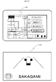
WO2017110233A1 - 車載装置 - Google Patents
車載装置 Download PDFInfo
- Publication number
- WO2017110233A1 WO2017110233A1 PCT/JP2016/081485 JP2016081485W WO2017110233A1 WO 2017110233 A1 WO2017110233 A1 WO 2017110233A1 JP 2016081485 W JP2016081485 W JP 2016081485W WO 2017110233 A1 WO2017110233 A1 WO 2017110233A1
- Authority
- WO
- WIPO (PCT)
- Prior art keywords
- gesture
- steering
- hand
- unit
- user
- Prior art date
Links
- 238000001514 detection method Methods 0.000 claims abstract description 104
- 230000033001 locomotion Effects 0.000 claims description 38
- 230000008859 change Effects 0.000 claims description 10
- 238000000034 method Methods 0.000 description 37
- 230000000694 effects Effects 0.000 description 30
- 238000010586 diagram Methods 0.000 description 23
- 230000008569 process Effects 0.000 description 18
- 125000002066 L-histidyl group Chemical group [H]N1C([H])=NC(C([H])([H])[C@](C(=O)[*])([H])N([H])[H])=C1[H] 0.000 description 14
- 238000009434 installation Methods 0.000 description 12
- 230000004048 modification Effects 0.000 description 10
- 238000012986 modification Methods 0.000 description 10
- 230000006870 function Effects 0.000 description 8
- 230000007704 transition Effects 0.000 description 8
- 238000012545 processing Methods 0.000 description 7
- 238000004891 communication Methods 0.000 description 6
- 238000013459 approach Methods 0.000 description 3
- 239000012141 concentrate Substances 0.000 description 3
- 238000010187 selection method Methods 0.000 description 3
- 230000035807 sensation Effects 0.000 description 3
- 230000005540 biological transmission Effects 0.000 description 2
- 230000004044 response Effects 0.000 description 2
- 230000003044 adaptive effect Effects 0.000 description 1
- 239000002131 composite material Substances 0.000 description 1
- 238000010276 construction Methods 0.000 description 1
- 239000004973 liquid crystal related substance Substances 0.000 description 1
- 238000012544 monitoring process Methods 0.000 description 1
- 238000003909 pattern recognition Methods 0.000 description 1
- 230000035484 reaction time Effects 0.000 description 1
- 230000000717 retained effect Effects 0.000 description 1
Images


Classifications
-
- G—PHYSICS
- G06—COMPUTING; CALCULATING OR COUNTING
- G06F—ELECTRIC DIGITAL DATA PROCESSING
- G06F3/00—Input arrangements for transferring data to be processed into a form capable of being handled by the computer; Output arrangements for transferring data from processing unit to output unit, e.g. interface arrangements
- G06F3/01—Input arrangements or combined input and output arrangements for interaction between user and computer
- G06F3/017—Gesture based interaction, e.g. based on a set of recognized hand gestures
-
- B—PERFORMING OPERATIONS; TRANSPORTING
- B60—VEHICLES IN GENERAL
- B60K—ARRANGEMENT OR MOUNTING OF PROPULSION UNITS OR OF TRANSMISSIONS IN VEHICLES; ARRANGEMENT OR MOUNTING OF PLURAL DIVERSE PRIME-MOVERS IN VEHICLES; AUXILIARY DRIVES FOR VEHICLES; INSTRUMENTATION OR DASHBOARDS FOR VEHICLES; ARRANGEMENTS IN CONNECTION WITH COOLING, AIR INTAKE, GAS EXHAUST OR FUEL SUPPLY OF PROPULSION UNITS IN VEHICLES
- B60K35/00—Arrangement of adaptations of instruments
-
- B60K35/10—
-
- B60K35/28—
-
- B60K35/29—
-
- B60K35/654—
-
- B—PERFORMING OPERATIONS; TRANSPORTING
- B60—VEHICLES IN GENERAL
- B60R—VEHICLES, VEHICLE FITTINGS, OR VEHICLE PARTS, NOT OTHERWISE PROVIDED FOR
- B60R16/00—Electric or fluid circuits specially adapted for vehicles and not otherwise provided for; Arrangement of elements of electric or fluid circuits specially adapted for vehicles and not otherwise provided for
- B60R16/02—Electric or fluid circuits specially adapted for vehicles and not otherwise provided for; Arrangement of elements of electric or fluid circuits specially adapted for vehicles and not otherwise provided for electric constitutive elements
-
- G—PHYSICS
- G01—MEASURING; TESTING
- G01C—MEASURING DISTANCES, LEVELS OR BEARINGS; SURVEYING; NAVIGATION; GYROSCOPIC INSTRUMENTS; PHOTOGRAMMETRY OR VIDEOGRAMMETRY
- G01C21/00—Navigation; Navigational instruments not provided for in groups G01C1/00 - G01C19/00
- G01C21/26—Navigation; Navigational instruments not provided for in groups G01C1/00 - G01C19/00 specially adapted for navigation in a road network
- G01C21/34—Route searching; Route guidance
- G01C21/36—Input/output arrangements for on-board computers
-
- G—PHYSICS
- G06—COMPUTING; CALCULATING OR COUNTING
- G06F—ELECTRIC DIGITAL DATA PROCESSING
- G06F3/00—Input arrangements for transferring data to be processed into a form capable of being handled by the computer; Output arrangements for transferring data from processing unit to output unit, e.g. interface arrangements
- G06F3/01—Input arrangements or combined input and output arrangements for interaction between user and computer
- G06F3/016—Input arrangements with force or tactile feedback as computer generated output to the user
-
- G—PHYSICS
- G06—COMPUTING; CALCULATING OR COUNTING
- G06F—ELECTRIC DIGITAL DATA PROCESSING
- G06F3/00—Input arrangements for transferring data to be processed into a form capable of being handled by the computer; Output arrangements for transferring data from processing unit to output unit, e.g. interface arrangements
- G06F3/01—Input arrangements or combined input and output arrangements for interaction between user and computer
- G06F3/048—Interaction techniques based on graphical user interfaces [GUI]
- G06F3/0481—Interaction techniques based on graphical user interfaces [GUI] based on specific properties of the displayed interaction object or a metaphor-based environment, e.g. interaction with desktop elements like windows or icons, or assisted by a cursor's changing behaviour or appearance
- G06F3/04817—Interaction techniques based on graphical user interfaces [GUI] based on specific properties of the displayed interaction object or a metaphor-based environment, e.g. interaction with desktop elements like windows or icons, or assisted by a cursor's changing behaviour or appearance using icons
-
- G—PHYSICS
- G06—COMPUTING; CALCULATING OR COUNTING
- G06V—IMAGE OR VIDEO RECOGNITION OR UNDERSTANDING
- G06V40/00—Recognition of biometric, human-related or animal-related patterns in image or video data
- G06V40/20—Movements or behaviour, e.g. gesture recognition
- G06V40/28—Recognition of hand or arm movements, e.g. recognition of deaf sign language
-
- B60K2360/146—
-
- B60K2360/1464—
-
- B60K2360/164—
-
- B60K2360/197—
-
- B—PERFORMING OPERATIONS; TRANSPORTING
- B60—VEHICLES IN GENERAL
- B60R—VEHICLES, VEHICLE FITTINGS, OR VEHICLE PARTS, NOT OTHERWISE PROVIDED FOR
- B60R16/00—Electric or fluid circuits specially adapted for vehicles and not otherwise provided for; Arrangement of elements of electric or fluid circuits specially adapted for vehicles and not otherwise provided for
- B60R16/02—Electric or fluid circuits specially adapted for vehicles and not otherwise provided for; Arrangement of elements of electric or fluid circuits specially adapted for vehicles and not otherwise provided for electric constitutive elements
- B60R16/037—Electric or fluid circuits specially adapted for vehicles and not otherwise provided for; Arrangement of elements of electric or fluid circuits specially adapted for vehicles and not otherwise provided for electric constitutive elements for occupant comfort, e.g. for automatic adjustment of appliances according to personal settings, e.g. seats, mirrors, steering wheel
- B60R16/0373—Voice control
-
- B—PERFORMING OPERATIONS; TRANSPORTING
- B62—LAND VEHICLES FOR TRAVELLING OTHERWISE THAN ON RAILS
- B62D—MOTOR VEHICLES; TRAILERS
- B62D1/00—Steering controls, i.e. means for initiating a change of direction of the vehicle
- B62D1/02—Steering controls, i.e. means for initiating a change of direction of the vehicle vehicle-mounted
- B62D1/04—Hand wheels
- B62D1/046—Adaptations on rotatable parts of the steering wheel for accommodation of switches
-
- G—PHYSICS
- G01—MEASURING; TESTING
- G01C—MEASURING DISTANCES, LEVELS OR BEARINGS; SURVEYING; NAVIGATION; GYROSCOPIC INSTRUMENTS; PHOTOGRAMMETRY OR VIDEOGRAMMETRY
- G01C21/00—Navigation; Navigational instruments not provided for in groups G01C1/00 - G01C19/00
- G01C21/26—Navigation; Navigational instruments not provided for in groups G01C1/00 - G01C19/00 specially adapted for navigation in a road network
- G01C21/34—Route searching; Route guidance
- G01C21/36—Input/output arrangements for on-board computers
- G01C21/3664—Details of the user input interface, e.g. buttons, knobs or sliders, including those provided on a touch screen; remote controllers; input using gestures
-
- G—PHYSICS
- G06—COMPUTING; CALCULATING OR COUNTING
- G06F—ELECTRIC DIGITAL DATA PROCESSING
- G06F3/00—Input arrangements for transferring data to be processed into a form capable of being handled by the computer; Output arrangements for transferring data from processing unit to output unit, e.g. interface arrangements
- G06F3/01—Input arrangements or combined input and output arrangements for interaction between user and computer
- G06F3/048—Interaction techniques based on graphical user interfaces [GUI]
- G06F3/0481—Interaction techniques based on graphical user interfaces [GUI] based on specific properties of the displayed interaction object or a metaphor-based environment, e.g. interaction with desktop elements like windows or icons, or assisted by a cursor's changing behaviour or appearance
- G06F3/0482—Interaction with lists of selectable items, e.g. menus
Definitions
- the present invention relates to an in-vehicle device.
- Japanese Patent Application Laid-Open No. 2004-133867 displays an operation menu of an in-vehicle device and a driver's hand image attached to the operation unit superimposed on a head-up display (HUD) so that the user can operate while viewing the image.
- HUD head-up display
- the in-vehicle device includes a gesture detection unit that recognizes a position of a user's hand within a predetermined range, a driving situation recognition unit that detects a driving situation of the vehicle, and a gesture detection unit.
- a gesture control unit that controls the state of the gesture operation based on the recognition result of the hand position, the gesture control unit, when the driving situation of the vehicle detected by the driving situation recognition unit is a predetermined invalidation target state, Disable gesture operations.
- the present invention it is possible to improve the safety and operability of the operation of the in-vehicle device by the driving driver.
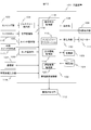
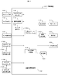
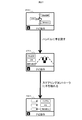
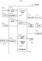
- FIG. 1 is a configuration diagram of an in-vehicle device 101 according to the first embodiment.
- the in-vehicle device control unit 102 is a part that controls the overall operation of the in-vehicle device 101, and performs an operation according to a program related to the messenger application 113 and the output information control unit 114 stored in the storage unit 123, thereby performing the messenger application 113 and the output.
- the function as the information control unit 114 is expressed.
- an application other than the messenger application 113 and the output information control unit 114 can be installed in the in-vehicle device 101, and these programs can be stored in the storage unit 123 at the time of shipment from the factory. It is also possible to store the data in the storage unit 123 by the user's selection through the unit 107 or an external connection IF (not shown) such as a USB terminal. Moreover, while controlling the basic operation as a car navigation system, the contents to be output are controlled based on various input information.
- the sensing unit 103 is a part that detects the distance between the user's hand and the sensor and the user's hand shake.
- an infrared distance sensor for example, an infrared distance sensor, a laser distance sensor, an ultrasonic distance sensor, a distance image sensor, an electrolytic sensor, an image sensor, etc.
- Sensor a microcomputer that performs data processing, and software that operates on the microcomputer.
- the sensor used for the sensing unit 103 is not particularly limited as long as it has a function for obtaining a signal obtained for detecting a distance to the user's hand and a hand shake.
- the gesture detection unit 104 Based on the sensor data obtained from the sensing unit 103, the gesture detection unit 104 detects whether or not a user's hand-holding and a predetermined gesture (for example, a hand gesture motion in the up / down / left / right direction) have been performed. For example, the hand-holding detects whether or not a predetermined sensor value has continued for a certain period of time, and the gesture operation detects the reaction time difference of the hand detection results among a plurality of sensors, respectively.
- a predetermined gesture for example, a hand gesture motion in the up / down / left / right direction
- the switch operation unit 105 is a hardware switch for operating the in-vehicle device 101, and a button press type or a jog dial type is mounted.
- the touch operation unit 106 transmits the touched coordinates to the in-vehicle device control unit 102 and operates the in-vehicle device 101.
- the microphone 115 acquires sound inside the vehicle.
- the speech recognition unit 116 converts speech from the input sound data into a character code string.
- the communication unit 107 connects to an external network and inputs / outputs various information. For example, input of information related to navigation, transmission / reception of messages, and the like.
- the external switch operation unit 117 is a switch operation unit installed at a location different from the in-vehicle device 101, and includes a steering switch installed near the steering wheel, a commander switch installed in the center console of the car, and the like.
- the display unit 108 is a device that presents video information to the user. For example, a display device such as an LCD (Liquid Crystal Display) and an arithmetic processing device necessary for display processing of video content or GUI (Graphical User Interface). And a device having a memory.
- the external display unit 109 is a display installed at a place in the vehicle different from the in-vehicle device 101, and displays an image.
- a head-up display (HUD) installed in front of the driver's seat can be used.
- the HUD can display various information while passing through the scenery in front of the driver (user).
- the sound output unit 110 is a part that outputs sound or sound.
- the speaker 111 outputs the sound from the sound output unit 110.
- the haptic IF output unit 112 is a part that transmits some tactile sensation information to the user.
- the haptic IF output unit 112 is configured by an ultrasonic array including a plurality of ultrasonic elements, and is pressured on a space at an arbitrary distance of the apparatus. Tell. Or you may provide a fan and provide the same effect.
- it may be comprised by the vibrator
- the messenger application 113 exchanges message data with the communication unit 107, and controls to store and output the input message. When transmitting a message, the transmission message is transmitted to the communication unit 107.
- the output information control unit 114 controls contents to be output to the display unit 108 or the external display unit 109.
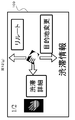
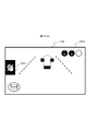
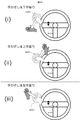
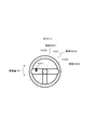
- FIG. 2A shows an installation example of the sensing unit 103. It is arranged on the driver side in the right-hand drive vehicle with respect to the display unit 108, and can detect the distance information of the object from the point of the sensor element and the movement of the object. As a result, as shown in the lower diagram in the figure, the space between the in-vehicle device 101 and the user is divided into a plurality of regions, and the region in which the user's hand exists is detected in detail. As shown in the figure, a distinction is made between an area 201 near the sensor position and an area 202 closer to the sensor position. The number of sensor elements, the installation position, and the detection area are not limited to this.
- the messenger application 113 When the messenger application 113 outputs video or audio information to the output unit such as the display unit 108, the external display unit 109, and the speaker 111, the messenger application 113 transmits the video or audio information to the output information control unit 114, and the output information control unit 114. In order to simplify the description, the messenger application 113 outputs video to the display unit 108 for the sake of simplicity. 113 uses an expression such as outputting sound.
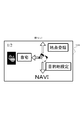
- the output information control unit 114 displays a display related to navigation and an icon 401 of the messenger application 113 on the display unit 108 (here, a center display) at the start of operation. Yes.
- the messenger application 113 is executed in the background by the in-vehicle device control unit 102 when the in-vehicle device 101 is activated, and the touch operation unit 106 detects a touch operation on the icon 401 or a user-specified gesture operation (for example, in front of the sensor).
- the gesture detection unit 104 detects a left hand gesture
- the output information control unit 114 activates the gesture.
- a display related to navigation and a display related to the messenger application 113 are displayed by the output information control unit 114.
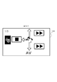
- the messenger application 113 When a message is received from the outside via the communication unit 107 (S301), the messenger application 113 outputs a sound effect when the message arrives, and the total number of messages received on the external display unit 109 is indicated by the icon in FIG. A message 402 is displayed to inform the user that the number of unread messages has increased.
- FIG. 4C is a display example when the half screen of the display unit 108 is displayed as the messenger application 113.
- the messenger application 113 When the touch operation unit 106 detects a touch on the area of the icon 403 in FIG. 4C, the messenger application 113 starts from the left of the area of the icon 403, and returns a stamp reply / fixed sentence reply, free speech reply, message return / send, respectively. A display for performing each operation is displayed on the display unit 108. Further, the messenger application 113 displays the current number of unread messages and the name of the sender of the message being read out on the external display unit 109 as indicated by 404 in the lower diagram of FIG.
- the gesture detection unit 104 detects a prescribed gesture operation by the user (for example, an upward or downward hand gesture operation) while reading a message (S306: Yes)
- the messenger application 113 is the latest unread message.
- the voice information is output to the speaker 111 so as to read out the message (S308).
- the messenger application 113 continues to output voice information so as to read out the unread messages in order from the oldest (S307).
- the display unit 108 and the external display unit 109 display FIG. While the last sender is displayed as in d), a reply operation is waited (S309).
- the messenger application 113 displays an icon 501 indicating that a reply operation by a gesture is possible as shown in FIG.
- the operation start condition is determined to be satisfied, and the external display unit
- the display is switched to 109 so that the menu that is the operation guide for the reply operation is slid from the right side of the screen, and a sound effect in which the menu appears is output (S311).
- the messenger application 113 outputs a sound effect that informs the user so that it can be recognized by hearing, and an icon as shown in FIG. 5B. By moving 501 to the right or changing the color of the icon, notification may be performed so that it can be recognized visually.
- the messenger application 113 when a user's hand is detected not in the area 202 but in the area 201 and a certain time (for example, 0.3 seconds) elapses, the messenger application 113 generates a sound effect indicating that the position of the hand is different. Output.
- the messenger application 113 when the user holds the hand, the user can perform the hand-holding operation while looking at the front without sending the line of sight to the hand.
- FIG. 2B and FIG. 2C show the details of the relationship between the detection state of the user's hand and the sound effect output.
- FIGS. 2B and 2C show the time axis and the sensor values of the sensing unit 103, respectively, and are diagrams showing boundaries where the sensor values are determined to be regions 201 and 202.
- FIG. FIG. 2B shows an example in which the user extends his / her hand toward the area 202 and holds his / her hand for a certain period of time.
- the gesture detecting unit 104 detects that a hand has entered the area 201
- the sound effect 1 is output.
- sound effect 2 is output when it is detected that the user has entered the area 202.
- the sound effect 3 is output and the display on the external display unit 109 is switched as described for S311.
- FIG. 2C is an example in the case where the hand is continuously held over the area 201.
- the sound effect 1 is output.
- the hand 201 is continuously detected in the area 201 for a time T2 or longer (for example, 0.3 seconds or longer)
- the sound effect 4 is output.
- the operation is the same as in the example of FIG. 2B (hereinafter, an operation of holding the hand over the area 202 for a time T1 or more may be simply referred to as “hand holding”).
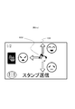
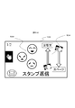
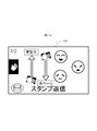
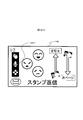
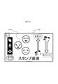
- FIG. 5C shows an example in which an operation menu capable of replying with a stamp is displayed.
- the icon 502 is an operation guide that means that when a hand is held up and a gesture of up / left / down is performed, a stamp corresponding to the gesture can be selected. Further, the display at the upper left half means the total number of displayed stamp candidates and the current page.
- the messenger application 113 selects a stamp corresponding to the direction and performs a reply operation (S313). Transition to the standby state S309.
- An icon 503 means a stamp candidate that can be currently selected.
- the icon 504 means that a corresponding operation is performed when a gesture operation corresponding to the displayed direction (an upward hand shake or a downward hand shake) is performed.
- the display of “standard text” switches the reply method to the standard text reply, and the display of “next page” switches the selection candidate of the stamp from the icon 503 to the next candidate group. Each means what you can do.
- the messenger application 113 deletes the operation guide from the display of the external display unit 109, A transition is made to the reply operation waiting state in S309 (S320).
- the messenger application 113 displays the content of the reply operation result (here, the selected stamp) on the display unit 108 and performs the reply operation on the external display unit 109 as shown in FIG. The user's name is displayed and the response is read aloud.
- FIG. 3B shows a simplified operation flow.
- the basic operation is as described above, and the description of the operation in each step is the same as that given the same step number in FIG. 3A, but with respect to S316 in this figure, the vertical direction is the same. Not only hand gestures but also various operations such as an operation with a steering switch may be accepted.
- a message when a message is received from the outside, it may be configured such that it is read out simultaneously with the reception, and the content of the received message may be displayed on the external display unit 109. This makes it easier for the user to grasp the message.
- the reply operation may be accepted at any time without waiting for the latest message to be read. Thus, the user can perform a reply operation at any time.
- a pressure point of the ultrasonic element array appears on the boundary of the region, or a tactile sensation is given on the vertical line of the region by a blower.
- the state transits to the stamp reply operation state, but before that, it may be configured to transit to the reply method selection state (stamp, fixed phrase, free utterance, etc.) good. Thereby, the user can select the reply method he / she wants to perform at the start of the reply operation.
- a hand is detected and an operation guide is displayed on the external display unit 109, and then a gesture is accepted.
- a predetermined time before the operation guide is displayed for example, 0.2 seconds before
- S319 the passage of a certain time is measured. If a predetermined operation (for example, a left hand gesture operation or a switch operation) is detected before satisfying this condition, the process proceeds to S320. It is good also as a structure. Thereby, the display of the external display unit 109 can be switched for navigation at a timing that the user likes.
- a predetermined operation for example, a left hand gesture operation or a switch operation
- the operation guide and the gesture direction displayed on the external display unit 109 are not limited to three directions, and any direction and number may be used. In that case, it is preferable to set a direction in which a gesture operation can be easily performed while sitting in the driver's seat. For example, a gesture performed toward the handle direction is not targeted because the hand may hit the handle during the operation.
- a gesture performed toward the handle direction is not targeted because the hand may hit the handle during the operation.
- the handle of the vehicle to be boarded is the right handle or the left handle can be set in advance on the setting screen, and when it is the left handle, it is displayed on the external display unit 109 as shown in FIGS.
- the operation guide to be recognized is the recognition target in the three directions of up, down, and right.
- FIGS. 7A and 7B correspond to FIGS. 5C and 5D, respectively.
- the hand used for the gesture will change, so the icon display and orientation will also change. Furthermore, since the appearance of various icons changes depending on the position of the handle, the user may be able to make settings individually. As a result, it becomes possible to perform an operation with an easy-to-use gesture operation according to the handle installation position for each vehicle type, and it becomes possible for the user to perform various operations with a gesture without difficulty while sitting in the driver's seat.
- the position where the hand is held is not limited to one place, and the hand may be held at a plurality of places.
- the hand may be held at a plurality of places.
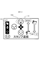
- the reply method may be determined depending on which sensor is placed over the hand.
- the sensor 103A is a stamp reply
- the sensor 103B is a fixed sentence reply
- the sensor 103C is a free utterance reply.
- the user can quickly select a reply method and perform a reply operation. It may be possible for the user to specify in advance which sensor corresponds to which method.
- FIG. 9 it is good also as a structure which detects a hand approach and a gesture using a camera for the sensing part 103.
- FIG. 9 A predetermined hand-shaped image is learned in advance, and the user's hand-holding is detected regardless of the distance and position from pattern recognition between the input video image and the learning data.
- a plurality of hand shapes when the hand is held up may be detected (901A to 903C), and a reply method may be selected.
- the user can start a reply operation without reaching the front of the sensing unit 103 and performing a gesture operation.
- the direction and number of gestures to be accepted may be changed according to the position and posture of the user's hand when detecting a hand hold. For example, as shown in FIG. 10 (a), when the user raises his / her hand with the elbow placed on the armrest and detects a hand hold, as shown in FIG. 10 (b), the left / bottom / right The direction is the recognition target. This is because it is considered difficult to perform an upward gesture in the user's posture in this situation, and these three directions are set as recognition targets. Furthermore, the user may include an arrangement can be set whether to which the gesture recognition target in advance. As a result, the user can perform gesture operations in a free posture.
- the operation menu for the reply operation is displayed on the external display unit 109.
- the display location and the display contents are changed according to the connection state and installation position of various devices. It is also good.
- a gesture operation guide is displayed on the center display as shown in FIG.
- the installation positions and connection states of the plurality of displays are managed, and the priority is determined.
- an operation guide is displayed on a display with a high priority, but when it cannot be used, such as when the HUD breaks down, it is displayed on the display with the next priority. In this case, the guide display time may be shortened or the amount of information displayed may be reduced according to the priority.
- the priority is set in the in-vehicle terminal so that the priority is determined based on the nature of the display connected to the in-vehicle terminal, which is set at the time of shipment from the factory or at the time of sale, set by the user on a setting screen (not shown) It can be set by a method such as
- the priority may be increased according to the installation position. Accordingly, when a device that is assumed to display an operation guide such as a HUD cannot be used, the operation guide can be displayed on an alternative display and operated.
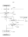
- FIG. 12A shows an operation flow at that time.
- S316 when a preparatory operation for performing a certain operation means is detected (S1201: Yes), an operation guide corresponding to the operation is displayed on the external display unit 109 (S1202).
- S1203: Yes Thereafter, when a selection operation is executed (S1203: Yes), a reply is made with the selected option (S1204).
- an operation guide as shown in FIG. 12B is displayed on the external display unit 109 when transitioning to the state of S315.
- the icon 1201 indicates that the upper icon can select an option by gesture, the middle icon can select an option by speech recognition, and the lower icon can select an option by a switch.
- FIG. Transition to a screen like An icon 1201 notifies that the steering operation is active by changing the icon color.
- stamp candidates corresponding to the buttons of the stacon are displayed.
- a reply operation is performed with a corresponding stamp according to the button of the pressed button. Note that if the fixed time has elapsed or the contact sensor of the stacon stops responding, the screen returns to the screen of FIG.
- a transition is made to a screen as shown in FIG.
- An icon 1201 indicates that speech recognition is in a standby state, and a display 1203 indicates that a utterance corresponding to each character is performed, and a stamp corresponding to the character can be selected. If the result of voice recognition matches any of the options, a corresponding stamp reply operation is performed. In the example of FIG. 12D, only characters corresponding to icons such as “fun” are displayed, but by displaying the transmitted icons side by side with the characters, the transmitted icons can be seen at a glance. Also good. If the voice recognition is used, the user can select a stamp to be transmitted without releasing his / her hand from the handle, which can contribute to further safe driving.
- the three types of operation means can be switched in the middle of any operation if a start trigger of each operation is detected.
- a gesture operation by a vertical hand gesture is accepted in that state.
- the reply operation means can be freely selected according to the driving situation and according to the user's preference without being limited to one operation means.
- each operation means is switched, by presenting which operation means can be operated at present and how to perform the operation, the user can quickly and intuitively understand the operation. The operation can be performed.
- FIG. 12 (e) presents navigation-related operations such as route setting to the home, location registration of the current location, and destination setting by voice as selection candidates when there is no application running in the background other than navigation. This is an example.
- FIG. 12F shows an example in which music stop, operation to skip to the next song, or skip to the previous song, etc. are presented as selection candidates when a hand is held during music playback or the like.
- FIG. 12G is an example in which when listening to traffic information or the like, when holding the hand, an operation for listening to details of the traffic information, reroute, destination change, etc. are presented as selection candidates.
- various operations can be quickly selected in accordance with the status of the application controlled by the in-vehicle device 101 being driven by the user.
- the in-vehicle device 101 allows the user to operate intuitively and quickly while looking forward while driving. Specifically, you can quickly switch the display of the messenger application, skip messages, etc. while looking forward. Further, in the case of an operation for selecting a plurality of options, it is possible to select a desired option while confirming the contents of the selection candidates while looking at the forward direction. Furthermore, when familiar with the operation, the options can be operated without looking at the display, so that the operation can be performed more safely and quickly.
- FIG. 13 is a configuration diagram of the in-vehicle device 101 according to the second embodiment.
- a vehicle information input unit 118, an operation means control unit 119, a driving load estimation unit 120, and a map DB (database) 121 are added.
- the vehicle information input unit 118, the operation unit control unit 119, and the driving load estimation unit 120 are also operated by the in-vehicle device control unit 102 according to the program stored in the storage unit 123, so that the vehicle information input unit 118, the operation unit control unit 119, the function as the driving load estimation unit 120 is expressed.
- the vehicle information input unit 118 is a part that acquires information related to a running vehicle.
- the vehicle information input unit 118 is connected to the vehicle via a CAN (Control Area Network), and the vehicle speed, accelerator opening, brake depth, blinker signal, steering angle, etc. Get etc.
- the operation means control unit 119 controls to which operation the operation input from the gesture detection unit 104, the voice recognition unit 116, and various switch operation units is reflected.
- the driving load estimation unit 120 estimates how much the user's driving load in driving operation is. For example, in addition to the various input signals from the vehicle information input unit 118 described above, information input from the communication unit 107 (map information, type of road on which the vehicle is traveling, distance to the preceding vehicle, etc.) is integrated, and the driving load Define levels in four levels (none, low, medium and high). “None” is a straight line with no obstacles in the vicinity, such as when the vehicle is stopped without waiting for a signal, or when the driver is driving without any special operation such as ACC (Adaptive Cruise Control). When driving on roads, “medium” is at a certain speed or higher, driving situations that require steering operation at all times, or when turning left or right at intersections. Situation, etc.
- the map DB 121 is a database that stores map information.
- the operation of the in-vehicle device 101 according to the second embodiment will be described in detail.
- the basic operation is the same as that described in the first embodiment, and the second embodiment is characterized in that the operation is controlled according to the output of the driving load estimation unit 120.
- the in-vehicle device control unit 102 defines in advance the driving load level output from the driving load estimation unit 120, the operation means that can be operated at that time, and the display contents that can be presented.
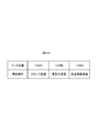
- FIGS. 14A to 14D show the definitions.
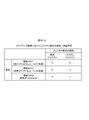
- FIG. 14A shows whether or not each operation means can be used at each operation load level.
- the driving load level is “none” or “low”
- a reply operation can be performed by all the operation means described in the first embodiment.
- the driving load level is “high”
- all operations are prohibited.
- the driving load is “medium”
- display of an operation guide by hand-holding and subsequent selection of an option by gesture operation are prohibited. This is because the operation with a hand-hold is an operation means forcing one-handed operation, and this operation is prohibited in a situation where the user should concentrate on the driving operation.
- the current operating load level is displayed as shown by an icon 1503 in FIG.
- This figure means a state where the driving load level is “medium”, and an icon 1501 indicates that the operation by the hand holding is prohibited as an icon 1501.
- the icon 1501 is emphasized by changing the display or color, and a warning sound or a warning sound is output to immediately stop holding the hand. Prompt.
- the user can grasp the current driving load situation and keep one hand away from the handle for a long time in an attempt to display the operation guide even when the handle operation is necessary. It can be prevented as much as possible.
- a direct utterance reply by voice recognition without using a hand or a direct gesture completed by a momentary operation can be used even in a situation where the driving load level is “medium”.
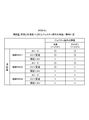
- FIG. 14 (b) is a definition regarding the operation load level and the output content of the center display.
- the messenger application 113 displays all the text of the message.
- a reply operation is performed from a basic operation such as touching an operation icon on the screen, all options such as a stamp candidate are also displayed.
- the driving load is “low” or “medium”
- the message text is not displayed and only the name of the message sender is displayed. Also, the operation system is not displayed using the touch operation.
- the driving load is “high”
- the screen of the messenger application 113 is also turned off, and a warning message corresponding to the situation (for example, “Warning!”) Is displayed.
- the driving load is “Low” or “Medium”
- the operating load level changes to “None” while performing a reply operation by holding the hand, it is displayed on the HUD.
- the operation can be performed even by a touch operation on the center display. For example, as shown in FIG. 16 (a), assuming that the stamp has been returned on the HUD, the center display as shown in FIG. Also displayed.
- the content is displayed on the center display like 1602 while maintaining the contents of the stamp candidate 1601 on the HUD and the arrangement relationship on the screen. Further, the contents of 1602 are arranged close to the driver side so that the driver can easily operate, and the stamp can be selected by a touch operation. Further, the remaining stamp candidates are arranged at positions far from the driver side on the screen as 1603.
- the driving load is switched to “Low” or “Medium” due to the start of the car while the operation is being performed on the center display while the vehicle is stopped, the display and selection of options on the center display Is stopped, the reply method that was in the middle of the operation is retained, the process proceeds to step S315 in FIG. 3A, and the operation is directly taken over.
- FIG. 14 (c) is a definition regarding the operation load level and the output contents of the HUD.
- the driving load level is “none” or “low”
- the name of the sender at the time of reading a message is displayed, and the operation guide at the time of reply operation is displayed.
- the driving load level is “medium”, it is displayed that the operation by hand-holding is prohibited or the operation guide display is taken over only when the driving load level is changed from “low” to “medium”. indicate.
- the driving load level is “high”, a warning message corresponding to the situation (for example, “attention between vehicles!”) Is displayed.
- FIG. 14 (d) is a definition regarding the driving load level and the sound output from the speaker.
- the driving load level is “None” to “Medium”, an operation sound or a reading voice at that time is output.
- the driving load level is “high”, only a warning sound is output. Even if the message is read out, the output is stopped. The stopped read-out message is resumed after the driving load level is lowered, and read again from the head of the message.
- the hand-holding detection algorithm which is designed to be able to operate quickly and without moving the line of sight from the front, allows touch operations and side-views to be permitted when stopped. It is possible to prevent erroneous detection due to an operation other than the operation.
- the user can operate intuitively and quickly while looking forward while driving, as well as a margin for stopping, etc.
- you can receive operations by a variety of means and a large amount of information, and in situations where you should concentrate on driving operations, other operations may focus attention other than driving operations Can be prevented and safe driving can be performed.
- the in-vehicle device has been described as an example.
- the present invention is not limited to this, and includes a display unit and an operation unit such as a personal computer, a digital signage, a construction machine, an aircraft, and a monitoring operator device. Can be applied.
- FIG. 17 is a configuration diagram of the in-vehicle device 101 according to the third embodiment. Compared to the configuration diagram of FIG. 1, an operation menu application 1701, a display output unit 1702, a steering controller 1703, a steering contact detection unit 1704, a commander controller 1705, and a commander contact detection unit 1706 are added.
- the operation menu application 1701 is software that displays an operation menu on the display unit 108 and the external display unit 109 in accordance with a program stored in the storage unit 123.
- the display output unit 1702 has a function of outputting a video signal to the display unit 108 when a display device that is not built in the in-vehicle device 101 is used as the display unit 108.
- the steering controller 1703 is a switch component provided in the steering and is used by the user to input an operation.
- the steering contact detection unit 1704 detects whether the user's hand is touching the switch part of the steering controller 1703.
- the commander controller 1705 is a switch component provided in an instrument panel or a center console in the vehicle, and is used for a user to input an operation.
- the commander contact detection unit 1706 detects whether the user's hand is touching the switch part of the commander controller 1705.
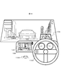
- FIG. 18 shows the appearance of the cockpit in the third embodiment.
- the display unit 108 is installed at the center of the instrument panel, and can be touched by the touch operation unit 106.
- a sensing unit 103 for detecting a gesture is provided on the upper right of the display unit 108.
- the external display unit 109 uses a HUD, and can display various information while passing through the scenery in front of the driver (user).
- a steering controller 1703 is provided in the steering.
- a commander controller 1705 is provided on the center console.
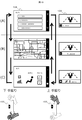
- FIG. 19 shows how the display contents of the display unit 108 and the external display unit 109 are changed by the upward and downward hand movements with respect to the sensing unit 103.
- Each display of (A), (B), and (C) of FIG. 19 shows a display in a screen mode controlled by the operation menu application 1701, (A) is an audio operation mode, and (B) is a navigation operation. Mode (C) is an air conditioner operation mode.
- Mode (C) is an air conditioner operation mode.
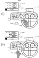
- FIG. 20 shows a state where the gesture and the steering controller 1703 are operated in the (B) navigation operation mode.
- a gesture operation menu 2001 is displayed on the external display unit 109. By moving the hand in one direction, it is guided that an item corresponding to the direction is selected.
- a steering controller operation menu 2002 is displayed as shown in FIG. 20 (ii).
- pressing one of the upper, middle, and lower switches of the steering controller 1703 guides selection of an item corresponding to the switch.
- the state of (ii) of FIG. 20 if the user puts his hand over the sensing unit 103 again without pressing any switch, the state of (i) of FIG. 20 is obtained.
- FIG. 21, FIG. 22, and FIG. 23 show screen transitions of the external display unit 109 in the series of operations described in FIG. 19 and FIG.
- FIG. 21 shows screen transitions in the (B) navigation operation mode
- FIG. 22 shows the (A) audio operation mode
- FIG. 23 shows (C) the air conditioner operation mode.
- FIG. 24 shows the details of the movement in the screen of the external display unit 109 in the (B) navigation operation mode.
- the gesture operation menu 2001 is displayed on the external display unit 109.
- FIG. 26A is a table showing the correspondence between gesture detection states and operation devices in the in-vehicle device 101 of the third embodiment.
- FIG. 26C is a table showing the correspondence between operation devices and display devices according to the running and stop states.
- the output information control unit 114 according to the third embodiment determines an operation device and a display device used for an operation of a predetermined menu according to FIGS. 26 (a) and 26 (c).
- the output information control unit 114 determines that the user is about to operate with a gesture.
- the hand is away from the sensing unit 103, it is determined that the user is about to operate with the steering controller 1703.
- the output information control unit 114 instructs the operation menu application 1701 to output a predetermined screen.
- the output information control unit 114 determines that the user is about to perform an operation using the gesture and steering controller 1703 and the commander controller 1705 when the vehicle is running. At that time, an operation menu is displayed on the HUD which is the external display unit 109. As a result, the user can visually recognize the operation menu with little line-of-sight movement from the state of visually confirming the front of the vehicle, and thus an effect of suppressing the influence on the driving operation by operating the operation menu is obtained.
- the steering controller operation menu 2002 when the user returns his hand to the steering wheel, the steering controller operation menu 2002 is displayed on the external display unit 109, but when the user tries to perform a driving operation with his hand returned to the steering wheel. It may be considered that the display of the steering controller operation menu 2002 is troublesome. Therefore, as shown in FIG. 27, when the user returns his hand to the steering wheel, a simple menu is displayed in which the menu display portion is reduced in the external display unit 109 as shown in 2701 of FIG. When the steering contact detection unit 1704 detects that the user touches the switch of the steering controller 1703, the steering controller operation menu 2002 may be displayed.
- the steering controller operation menu 2002 is not displayed until just before the user operates the steering controller 1703, so that the troublesomeness of the menu display can be reduced, and the display on the external display unit 109 can be replaced with other information necessary for driving.
- the effect that it can be effectively used for the display of is obtained.
- FIG. 28 shows the external appearance of the operation of the in-vehicle device 101 in the fourth embodiment.
- a state in which a commander operation menu 2801 is displayed on the external display unit 109 when the user brings his hand close to the commander controller 1705 is added.
- a camera is used for the sensing unit 103 as shown in FIG.
- the sensing unit 103 according to the fourth embodiment detects in which direction the user's hand is moving around the sensing unit 103.
- the sensing unit 103 may be a sensing device other than a camera as long as the direction in which the user's hand is moving can be detected.
- FIG. 28 shows a state in which the gesture and operation by the steering controller 1703 and the commander controller 1705 are performed in the (B) navigation operation mode.
- a steering controller operation menu 2002 is displayed as shown in (i) of FIG. Is done.
- an operation menu 2801 is displayed. In the state of (ii) of FIG. 28, it is guided that one item is selected by rotating the rotary controller corresponding to the rotary controller mounted on the commander controller 1705.
- FIG. 26B is a table showing selection of operation devices according to the position and movement direction of the hand in the in-vehicle device 101 according to the fourth embodiment.
- the output information control unit 114 according to the fourth embodiment determines an operation device to be used for a predetermined menu operation according to FIG. As illustrated in FIG. 26B, when the hand is near the sensing unit 103, the output information control unit 114 determines that the user is about to operate with a gesture. When the user's hand moves from the sensing unit 103 to the direction or position of the steering controller 1703, it is determined that the user is about to operate with the steering controller 1703.
- the output information control unit 114 instructs the operation menu application 1701 to output a predetermined screen. As a result, it is possible to display an operation menu and an operation guide suitable for the operation device that the user intends to operate, and an effect that the user can smoothly perform an operation using a desired operation device is obtained.
- the operation menu when displaying the operation menu, it may be based on the pointing direction of the user detected by the sensing unit 103 instead of based on the direction or position of the user's hand moving from the sensing unit 103.
- the sensing unit 103 detects that the user points to the air conditioner operation panel 2901, and based on this, the external display unit 109 is used for air conditioner operation.
- a steering controller operation menu 2302 may be displayed. Thereby, an effect that a desired operation menu can be displayed more smoothly without the user once holding the hand over the sensing unit 103 is obtained.
- FIG. 30 is a configuration diagram of the in-vehicle device 101 according to the fifth embodiment. Compared to the configuration diagrams of FIGS. 13 and 17, a steering operation detection unit 3001, a driving situation recognition unit 3002, and a gesture control unit 3003 are added.
- the driving situation recognition unit 3002 and the gesture control unit 3003 represent functions realized by executing the program stored in the storage unit 123 by the in-vehicle device control unit 102 as function blocks.
- the steering operation detection unit 3001 detects the steering operation status by the user based on the steering angle information acquired by the vehicle information input unit 118 and outputs the detected steering operation status to the driving status recognition unit 3002.
- the driving situation recognition unit 3002 detects the driving situation of the vehicle based on the output of the steering operation detection unit 3001. When the driving situation recognition unit 3002 determines that the driving situation of the vehicle is in a predetermined state to be described later, it outputs a gesture operation invalidation command to the gesture control unit 3003.
- the gesture control unit 3003 normally outputs the input from the gesture detection unit 104 to the operation menu application 1701 so that the operation based on the gesture is valid.
- the gesture control unit 3003 discards the input from the gesture detection unit 104 and invalidates it, and makes the operation based on the gesture invalid.
- the gesture control unit 3003 may stop the operation of the gesture detection unit 104, that is, stop the gesture detection by the gesture detection unit 104 when the driving condition recognition unit 3002 outputs an invalidation command.
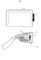
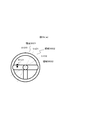
- FIG. 31 is a view showing the appearance of the cockpit in the present embodiment.
- a sensing unit 3101 for detecting a gesture is provided on the left side in the steering of the right-hand drive vehicle. Similar to the sensing unit 103 described in the first to fourth embodiments, the sensing unit 3101 is a part that detects the distance between the user's hand and the sensor and the user's hand shake.
- the external display unit 109 uses a HUD, and can display various information while passing through the scenery in front of the driver (user).
- the display unit 108 is installed at the center of the instrument panel and can be touched by the touch operation unit 106.
- Display corresponding to the gesture operation detected by the sensing unit 3101 is performed on the display unit 108 or the external display unit 109.
- the output information control unit 114 shown in FIG. 30 instructs the operation menu application 1701 to output a predetermined screen
- the operation menu related to the gesture operation is displayed on the display unit 108 or the external display unit 109.
- the operation menu application 1701 is software that displays an operation menu on the display unit 108 and the external display unit 109 in accordance with a program stored in the storage unit 123.
- the installation position of the sensing unit 3101 is changed from the sensing unit 103 shown in FIG. 2 and the like.
- the gesture detection area that is in the vicinity of the display unit 108 is the steering.
- To the left of The display unit 108 is displayed in accordance with the display content of the display unit 108 or the external display unit 109 being changed by a gesture such as upward or downward in the vicinity of the left side of the steering and the steering angle detected by the steering operation detection unit 3001.
- it is characterized in controlling whether to change the operation menu and operation guide displayed on the external display unit 109, that is, whether to accept the user's gesture operation as valid.
- the user can perform a gesture operation with a small movement in the vicinity of the steering wheel without releasing a large hand from the steering wheel while driving, and at the same time, the gesture operation is switched between valid / invalid depending on the steering angle.
- the steering operation detection part 3001 demonstrated the example which detects the operation condition of steering based on information, such as a steering angle which the vehicle information input part 118 acquired, it is not restricted to this, A steering angle is used using a camera or a sensor.
- the configuration may be such that the steering operation of the user is detected.
- a gesture detection area 3201 in FIG. 32 and FIG. 33 is an area in which the sensing unit 3101 visualizes an area where a user's hand movement is detected. As described above, in the present embodiment, the gesture detection area 3201 is set near the left side of the steering wheel, and the user performs a gesture operation with the left hand.
- FIG. 32 (i) shows a gesture operation of a hand movement in which the hand moves across the gesture detection area 3201 from the top to the bottom without stopping the hand in the gesture detection area 3201.
- FIG. 32 (ii) shows a gesture operation for moving the hand so as to cross the gesture detection area 3201 from below without stopping the hand in the gesture detection area 3201.
- these two gesture operations are collectively referred to as “direct gesture”.
- FIG. 33 shows a gesture operation method of moving a hand after a hand hold that temporarily stops the hand in the gesture detection area 3201, and this is referred to as a “hand hold gesture” in the present embodiment.
- a gesture operation menu 2001 as shown in FIG. 20 (i) is displayed on the external display unit 109.
- an item corresponding to the direction is selected by moving the hand in the downward, upward, or left direction from the position where the user holds the hand.
- “Destination setting” is selected.
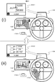
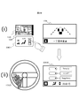
- FIG. 34 is a diagram illustrating an example of an operation using the direct gesture of FIG. 32, and shows that processing for the gesture operation changes according to the steering angle of the steering.
- FIG. 34 (i) shows a state where the steering operation detection unit 3001 detects that the steering is hardly turned, that is, a state where the steering angle 3410 is almost zero. In this state, when a downward hand gesture with respect to the gesture detection area 3201 is detected, the display content of the display unit 108 is changed from the audio operation mode to the air conditioner by the operation of the operation menu application 1701 according to the control of the output information control unit 114. Switch to operation mode.
- FIG. 34 (ii) shows a state where the steering angle 3411 is not zero, that is, a state where the steering is being turned.
- the gesture control unit 3003 performs control to invalidate the user's gesture operation detected by the gesture detection unit 104.
- the output information control unit 114 displays the operation menu related to the gesture operation as described above even when the downward gesture with respect to the gesture detection area 3201 is detected. Control for displaying on the external display unit 109 is not executed.
- the display content of the display unit 108 shown in the lower right of FIG. 34 (ii) remains in the audio operation mode, indicating that the gesture operation has been invalidated.
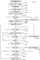
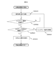
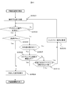
- FIG. 35 is a flowchart showing the operation of the in-vehicle device 101.
- the in-vehicle device 101 executes a program whose operation is represented by FIG.
- step S3501 the gesture detection unit 104 starts waiting for input from the user, and proceeds to step S3502.
- step S3502 it is determined whether or not the gesture detection unit 104 has detected a gesture operation. If it is determined that the gesture operation has been detected, the process proceeds to step S3503. If it is determined that the gesture operation has not been detected, the process proceeds to step S3502.
- the gesture operation in this step is the above-described direct gesture or hand-holding gesture.
- step S3503 the driving situation recognition unit 3002 determines whether the steering angle is equal to or less than a predetermined threshold based on information from the steering operation detection unit 3001. This threshold value is stored in the storage unit 123. If it is determined that the steering angle is equal to or less than the threshold, the process proceeds to step S3504. If it is determined that the steering angle is greater than the threshold, the process proceeds to step S3505.
- step S3504 the output information control unit 114 and the operation menu application 1701 execute processing corresponding to the gesture operation detected in step S3502, and the program whose operation is represented in FIG.
- the process corresponding to the gesture operation is, for example, transition of the display unit 108 or the external display unit 109 shown in FIG. 34 (i) or execution of a selection operation.
- step S3505 the driving situation recognition unit 3002 outputs an invalidation command for invalidating the gesture operation to the gesture control unit 3003.
- the gesture control unit 3003 invalidates the gesture operation by invalidating the input from the gesture detection unit 104 or stopping the operation of the gesture detection unit 104 as described above. . Thereafter, the process returns to step S3501.
- step S3504 is executed for the first time. Is done.
- the output information control unit 114 causes the display unit 108 or the external display unit 109 to display a gesture operation menu indicating a gesture operation candidate corresponding to the movement of the user's hand after the hand is held over. .
- a gesture operation menu 2001 as shown in FIG. 20 (i) is displayed on the external display unit 109.
- step S3504 is executed again, so that the gesture is supported according to the gesture operation menu displayed on the display unit 108 or the external display unit 109. Is performed.
- step S3505 is executed and the gesture operation is invalidated.
- the output information control unit 114 does not display the gesture operation menu as described above on the display unit 108 or the external display unit 109 because step S3504 is not executed.
- the output information control unit 114 does not change the display content of the display unit 108 or the external display unit 109. After that, even if the user performs a hand movement operation to move the hand held over, the gesture operation corresponding to the hand movement is not executed.
- step S3502 after gesture detection is performed in step S3502, the gesture operation detected in step S3505 is ignored, and the gesture recognition result is not reflected in the function operation, thereby invalidating the gesture operation.
- the gesture operation may be invalidated by invalidating the gesture recognition function itself without performing gesture detection by the gesture detection unit 104.
- the in-vehicle device 101 includes a gesture detection unit 104 that recognizes the position of a user's hand in a predetermined gesture detection region 3201, a driving situation recognition unit 3002 that detects a driving situation of the vehicle, and a gesture detection unit 104.
- a gesture control unit 3003 for controlling the state of the gesture operation based on the recognition result of the hand position.
- the gesture control unit 3003 invalidates the gesture operation when the driving situation of the vehicle detected by the driving situation recognition unit 3002 is the invalidation target state. Since the in-vehicle device 101 is configured as described above, the gesture operation is invalidated based on the driving state of the vehicle, and the safety and operability of the operation of the in-vehicle device by the driver during driving can be improved.
- the in-vehicle device 101 includes a steering operation detection unit 3001 that detects a steering operation for driving the vehicle, and an output information control that controls display contents of the display unit 108 or the external display unit 109 connected to the in-vehicle device 101.
- the driving situation recognition unit 3002 detects the driving situation of the vehicle based on the steering operation.
- the invalidation target state is a state in which the steering operation amount of the user detected by the steering operation detection unit 3001, that is, the steering angle exceeds a predetermined threshold, that is, a prescribed operation amount.
- the output information control unit 114 does not change the display on the display unit 108 or the external display unit 109 even when the position of the user's hand is in the gesture detection area 3201. For this reason, if the steering operation amount exceeds a predetermined operation amount, the display on the display unit 108 or the external display unit 109 is not transitioned even if a direct gesture is performed. It will not be disturbed.
- the output information control unit 114 detects that the user has held the hand in the gesture detection area 3201, and the gesture detection unit 104 detects that the user's hand is held in step S3504.
- a gesture operation menu 2001 as shown in FIG. 20 (i) showing the gesture operation candidates corresponding to the above operation is displayed on the display unit 108 or the external display unit 109.
- the output information control unit 114 does not display the gesture operation menu 2001 on the display unit 108 or the external display unit 109.
- the gesture operation menu is not displayed on the display unit 108 or the external display unit 109 even if a hand-holding gesture is performed, and the gesture operation is not accepted.
- the user can be made aware.
- the in-vehicle device 101 includes a steering operation detection unit 3001 that detects a steering operation for driving the vehicle.
- the invalidation target state is a state in which the steering operation amount of the user detected by the steering operation detection unit 3001 exceeds a predetermined threshold, that is, a prescribed operation amount.
- the gesture control unit 3003 invalidates the gesture operation by stopping the operation of the gesture detection unit 104 or invalidating the input from the gesture detection unit 104.
- the steering angle exceeds the threshold value, it is considered that the user is turning the steering wheel to perform the driving operation. That is, there is a high possibility that the hand is moved for driving operation near the steering.
- the steering operation amount is an angle of steering operated by the user.
- the driving situation recognition unit 3002 evaluates the steering angle, that is, the steering angle, based on the output of the steering operation detection unit 3001.
- the steering operation speed that is, the steering angular speed may be evaluated. That is, in step S3503 in FIG. 35, it may be determined whether the steering angular velocity, that is, the steering operation speed is equal to or less than a predetermined threshold value. According to this modification, in addition to the operational effects of the fifth embodiment, the following operational effects are obtained.
- the steering operation amount is an operation speed of the steering operated by the user.
- the state where the steering angular velocity is almost zero is a state where the steering angle remains constant, and the user turns the steering a certain amount to perform driving operation, but slowly turns a curve with a large curvature. It is considered that the amount of operation with respect to the steering is small. In such a case, it is considered that the user can afford to perform an operation other than the driving operation regardless of the size of the steering angle. Therefore, by enabling the gesture operation, the gesture operation is performed in more cases. It can be performed and usability can be improved.
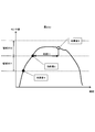
- FIG. 36 (a) is a diagram illustrating an example in which the steering angle in the steering operation is defined as a plurality of regions.
- a region between the steering angle SA00 and the steering angle SA01 is set as a region 3601, where the steering wheel is slightly turned. 3603.
- the area division is not limited to this, and the area may be divided more finely.
- FIG. 36B is a diagram illustrating the correspondence between the steering angle and the validity / invalidity of the gesture operation.
- the gesture control unit 3003 determines which gesture operation type is to be validated among a plurality of gesture operations according to the steering angle in accordance with FIG. For example, when the steering angle is in the region 3601, the gesture control unit 3003 validates both the direct gesture shown in FIG. 32 and the hand-holding gesture shown in FIG. This is because the steering angle for driving is not so much performed because the steering angle is small, and the hand movement performed in the gesture detection area 3201 near the steering is performed by the user for the gesture operation. It is possible.
- the gesture control unit 3003 invalidates both the direct gesture and the hand-holding gesture. This is because the steering angle is large, so the user concentrates on the steering operation for driving, and the possibility of performing the gesture operation is low, and the steering operation performed by the user for driving is erroneously recognized as a gesture operation. It is intended to prevent that.
- the gesture control unit 3003 validates only the direct gesture and invalidates the hand-holding gesture. This is because the characteristics of how to move the hand in direct gesture and hand-holding gesture are considered. While direct gestures end with a short hand gesture, hand-holding gestures move the hand over the gesture detection area 3201 for a certain period of time to perform the operation, so there is little steering operation for driving, and device operation It is suitable for performing when there is a relatively large margin. For this reason, considering the amount of work required for the steering operation for driving, it is determined that the user is unlikely to perform a hand-hold gesture when the amount of work is large, and the hand-hold gesture is controlled to be invalid.
- control is not limited to this, and for example, the determination may be made using only the region 3601 and the region 3603 or may be divided into four or more regions.
- the gesture control unit 3003 invalidates only a specific gesture operation from a plurality of gesture operations performed by the user based on the steering operation amount. Therefore, the gesture operation accepted according to the steering operation amount can be limited.
- the driving situation recognition unit 3002 increases gesture operations that are invalidated when the steering operation amount increases. For this reason, it is possible to reduce the number of gesture operations that are accepted as the user is less likely to perform a gesture operation and the possibility that a steering operation for driving is mistaken as a gesture operation is higher. Further, it is possible to perform fine gesture recognition processing with few false recognitions by controlling whether to accept the gesture operation of the user as valid by using the steering operation amount recognized by the driving situation recognition unit 3002 in a composite manner. It becomes possible.
- the configuration of the in-vehicle device 101 in the sixth embodiment is the same as that of the fifth embodiment. However, the operation of the vehicle device control unit 102 is different from that of the fifth embodiment.
- the driving status recognition unit 3002 is based on not only the steering operation status output from the steering operation detection unit 3001 but also information such as the vehicle speed, the accelerator opening, the winker signal based on the operation of the direction indicator, and the like acquired by the vehicle information input unit 118. , Recognize the driving situation.
- the driving situation to be recognized includes, for example, a state where the blinker signal is ON and the vehicle speed is zero, that is, a state where the vehicle is stopped, a state where the steering is turned rightward during traveling, and the like.
- the operation of the in-vehicle device 101 in the sixth embodiment will be described.
- the basic operation is the same as that described in the fifth embodiment.
- the operation speed of the steering by the user recognized by the driving situation recognition unit 3002 (for example, it is characterized by controlling whether or not a user's gesture operation is accepted as valid in accordance with on / off of a blinker signal (direction indicator), vehicle speed, and the like.
- FIG. 37 is a flowchart showing the operation of the in-vehicle device 101 according to the sixth embodiment.
- the same steps as those in FIG. 35 in the fifth embodiment are denoted by the same step numbers, and the description thereof is omitted.
- step S3501 the gesture detection unit 104 starts waiting for input from the user, and proceeds to step S3502.
- step S3502 it is determined whether or not the gesture detection unit 104 has detected a gesture motion. If it is determined that the gesture has been detected, the process proceeds to step S3506. If it is determined that the gesture has not been detected, the process remains in step S3502.
- step S3506 the driving situation recognition unit 3002 determines whether or not the vehicle speed is zero, that is, whether the vehicle is stopped or traveling. If it is determined that the vehicle speed is zero, the process proceeds to step S3504. It progresses to step S3507.
- step S3507 the driving situation recognition unit 3002 determines whether or not the direction indicator is off, that is, whether or not the blinker signal is off. It is determined whether or not there is a high possibility of performing a steering operation for driving by turning on and off the direction indicator. If it is determined that the direction indicator is off, the process proceeds to step S3508. If it is determined that the direction indicator is on, the process proceeds to step S3505.
- step S3508 the driving situation recognition unit 3002 determines whether or not the steering operation speed, that is, the angular speed is equal to or less than a predetermined threshold value. If it is determined that the value is less than or equal to the threshold, the process proceeds to step S3504. If it is determined that the value is greater than the threshold, the process proceeds to step S3505. In step S3505, which is executed when the vehicle speed is not zero, the direction indicator is on, or the steering angular velocity is greater than the threshold, the driving situation recognition unit 3002 ignores the gesture motion signal detected in step S3502, The process returns to S3501. In step S3504, the operation menu application 1701 executes an operation corresponding to the gesture motion detected in step S3502, and the program whose operation is represented by FIG. 37 is terminated.
- the invalidation target state where the gesture operation is invalidated is a state where at least the vehicle speed is not zero. Therefore, it is estimated that there is a possibility that the steering operation is performed due to the traveling of the vehicle, and it is possible to avoid erroneously recognizing the hand moved for the steering operation.
- the invalidation target state in which the gesture operation is invalidated further includes a state in which the direction indicator of the vehicle is on, in addition to a state in which the steering angular velocity exceeds the threshold value. Therefore, it can be estimated that there is a possibility that the steering operation is performed when the direction indicator is on, and it is possible to avoid erroneous recognition of the hand moved for the steering operation.
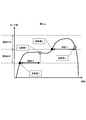
- FIG. 38 (a) is a diagram showing the definition of the region indicating the steering angle in the steering operation and the definition of the angular velocity AV.
- the steering angle is defined as a region 3601 between the steering angle SA00 and the steering angle SA01, a state where the steering wheel is slightly turned, and a region 3602 between the steering angle SA01 and the steering angle SA02.
- a state in which the steering wheel is turned largely by a steering angle SA02 or more is defined as a region 3603.
- the angular velocity AV takes a positive value regardless of the direction of rotation of the handle.
- FIG. 38B is a diagram showing a steering amount that is a combination of a steering angle and an angular velocity, and which gesture operation type is valid among a plurality of gesture operations for each steering amount.
- the angular velocity AV is substantially zero, for example, the angular velocity is 5 degrees or less per second
- the threshold value in the figure is, for example, an angular velocity of 15 degrees per second.
- the gesture control unit 3003 determines that the hand movement detected in the gesture detection region 3201 is for a gesture operation by the user. To do. Therefore, both direct gestures and hand-holding gestures are valid. On the other hand, also in the area 3601, when the steering angular velocity AV is larger than the threshold value, it is determined that the steering operation is busy and the driving operation is prioritized, and both the direct gesture and the hand-holding gesture are invalidated. .
- both the direct gesture and the hand-holding gesture are enabled, and when the steering angular velocity AV is larger than the threshold, both the direct gesture and the hand-holding gesture are performed. Invalid. If the steering angular velocity AV is not zero but smaller than the threshold value, only the direct gesture is validated and the hand-hold gesture is invalidated.
- the driving operation is preferentially determined because the steering angle is large, and both the direct gesture and the hand-holding gesture are invalid regardless of the magnitude of the steering angular velocity AV.
- the steering operation amount is a combination of a steering angle and a steering operation speed operated by the user
- the output information control unit 114 can display the display unit 108 or the steering operation speed according to the combination of the steering angle and the steering operation speed.
- the display on the external display unit 109 is made different. That is, according to the combination of the steering angle and the steering angular velocity AV, the gesture control unit 3003 determines which type of gesture operation is valid among a plurality of gesture operations. As a result, if the gesture operation is determined to be valid, the output information control unit 114 changes the display on the display unit 108 or the external display unit 109 according to the gesture operation.
- the output information control unit 114 does not change the display on the display unit 108 or the external display unit 109.
- the steering rudder angle and the steering angular speed are combined to determine whether the gesture operation is valid / invalid.
- the steering rudder angle is a constant amount, such as when driving stably on a curve or the like. In a case where the driving operation is hardly performed, it is possible for the user to perform a gesture operation on the target device, and it is possible to obtain an effect of improving usability while suppressing a false recognition rate of the gesture operation.
- FIG. 39 (i) shows an example of direct gesture operation when the steering wheel is rotated to the right, that is, when the vehicle is running on a right curve, turning right, or changing the lane to the right lane.
- FIG. 39 (ii) shows an example in which the steering is rotated counterclockwise.
- FIG. 40 is a diagram showing which one of the downward gesture and the upward gesture of the direct gesture operation is valid in each of the steering right rotation and the steering left rotation.
- FIG. 39 (i) in which the steering is rotated to the right, it is assumed that the hand passes the gesture detection region 3201 from the left to the right by moving the hand with the steering. For this reason, the upward gesture of a direct gesture that is easily confused with a driving operation is invalidated and is not recognized as a gesture operation.
- FIG. 41 is a flowchart illustrating the operation of the in-vehicle device 101 in the second modification of the sixth embodiment.
- step S3510 is added.
- step S3510 which is executed when a negative determination is made in step S3508, the driving condition recognition unit 3002 determines whether or not the movement direction of the hand movement detected in step S3502 matches the rotation direction of the steering detected in step S3508. to decide.
- the coincidence in this step is an upward hand shake when the steering wheel is rotated clockwise and a downward hand gesture when the steering wheel is rotated counterclockwise. If it is determined that they match, the process proceeds to step S3505. If it is determined that they do not match, the process proceeds to step S3504.
- the invalidation of the gesture operation means that a gesture operation for moving a hand in the same direction as the user's steering operation direction detected by the steering operation detection unit 3001 is not accepted.
- gesture control that is easily confused with the rotation direction of the steering wheel is eliminated by performing control to change the validity / invalidity of the downward gesture and the upward gesture within the gesture according to the rotation direction of the steering wheel.
- the effect of improving the accuracy of gesture recognition can be obtained.
- the effect that the steering operation for driving and the movement of the hand for gesture operation can be appropriately distinguished is obtained.
- FIG. 42 is a diagram illustrating the relationship between the steering and the gesture detection area.
- FIG. 42 (i) is an example in which the sensing unit 4001 is installed not on the steering but on a sensor installation location 4002 such as a base that does not rotate with the steering.
- FIG. 42 (ii) is an example in which the sensing unit 3101 is provided on the steering.
- the gesture detection area 3201 moves to the upper right together with the steering.
- FIG. 42 (iii) shows an example in which the steering is rotated clockwise from the state of FIG. 42 (i). In this case, the gesture detection area 3201 does not move even when the steering wheel is rotated, and the gesture detection area 3201 is always provided at the same place.
- the user can perform a gesture operation in the vicinity of the steering wheel without greatly releasing his hand during driving, and an effect of realizing a user-friendly device operation can be obtained.
Abstract
車載装置は、所定の範囲内にあるユーザの手の位置を認識するジェスチャー検出部と、車両の運転状況を検出する運転状況認識部と、ジェスチャー検出部による手の位置の認識結果に基づくジェスチャー操作の状態を制御するジェスチャー制御部とを備え、ジェスチャー制御部は、運転状況認識部が検出した車両の運転状況が所定の無効化対象状態であるときに、ジェスチャー操作を無効化する。
Description
本発明は、車載装置に関する。
特許文献1には、車載機器の操作のメニューと、操作部に添えられたドライバーの手の映像とを、ヘッドアップディスプレイ(HUD)に重畳して表示し、その映像を見ながら操作ができるようにすることで、車載機器の選択操作が簡単で早く、運転の妨げにならないように操作できる車載機器の操作装置について記載されている。
しかしながら、運転中における車載機器の操作において、特許文献1に記載の技術では、操作に関わるメニューがHUDに常に表示されるため、運転操作の妨げになる恐れがある。また、操作を行うためには、操作のための専用のデバイスを車内の何れかの場所に設置する必要があり、コストが増すとともに設置における制約が発生してしまう。さらに、音声のみのインターフェースを用いた場合でも、音声認識に必要な処理の処理時間や、読み上げられる音声を聞くための時間が必要となり、操作性や利便性が損なわれてしまう。
本発明の第1の態様によると、車載装置は、所定の範囲内にあるユーザの手の位置を認識するジェスチャー検出部と、車両の運転状況を検出する運転状況認識部と、ジェスチャー検出部による手の位置の認識結果に基づくジェスチャー操作の状態を制御するジェスチャー制御部とを備え、ジェスチャー制御部は、運転状況認識部が検出した車両の運転状況が所定の無効化対象状態であるときに、ジェスチャー操作を無効化する。
本発明によれば、運転中のドライバーによる車載機器の操作の安全性や操作性を向上することができる。
以下、本発明の実施の形態を、図面を参照して詳細に説明する。
(第1の実施の形態)
≪構成の説明≫
図1は第1の実施の形態における車載装置101の構成図である。
車載装置制御部102は本車載装置101の動作全体を制御する部分であり、記憶部123に格納されているメッセンジャーアプリケーション113および出力情報制御部114に関するプログラムに従って演算を行うことでメッセンジャーアプリケーション113および出力情報制御部114としての機能を発現する。なお、車載装置101にはメッセンジャーアプリケーション113および出力情報制御部114以外のアプリケーションを搭載することができ、これらのプログラムは工場出荷時に記憶部123に記憶しておくことが可能であり、また、通信部107を介して、もしくはUSB端子などの図示しない外部接続IFを介して、ユーザの選択により記憶部123に記憶させることも可能である。また、カーナビゲーションシステムとしての基本的な動作を制御するとともに、各種入力情報に基づいて、出力する内容を制御する。
センシング部103はユーザの手とセンサ間の距離及び、ユーザの手振りを検出する部分であり、例えば、赤外線距離センサ、レーザ距離センサ、超音波距離センサ、距離画像センサ、電解センサ、イメージセンサ、などのセンサと、データ処理を行うマイコン、及びマイコン上で動作するソフトウェアから構成される。センシング部103に用いるセンサは、特に限定されず、ユーザの手までの距離と手振りを検出するために得られる信号を、得られる機能を有すればよい。
ジェスチャー検出部104は、センシング部103から得られるセンサデータに基づいて、ユーザによる手かざしと、あらかじめ規定した所定のジェスチャー(例えば上下左右の方向への手振り動作)が行われたかどうかを検出する。例えば、手かざしは、所定のセンサ値が一定時間継続したかどうかを、ジェスチャー動作は複数のセンサ間における手の検知結果の反応時間差を解析して、それぞれ検知する。
スイッチ操作部105は、車載装置101の操作を行うためのハードウェアスイッチであり、ボタン押下型や、ジョグダイヤル型のものが搭載される。
タッチ操作部106は、タッチされた座標を車載装置制御部102に送信し、車載装置101の操作を行う。
マイクロホン115は、車両内部の音の取得を行う。
音声認識部116は、入力した音データから音声を文字コード列に変換する。
通信部107は、外部のネットワークと接続し、各種情報の入出力を行う。例えば、ナビゲーションに関わる情報の入力や、メッセージの送受信、などである。
タッチ操作部106は、タッチされた座標を車載装置制御部102に送信し、車載装置101の操作を行う。
マイクロホン115は、車両内部の音の取得を行う。
音声認識部116は、入力した音データから音声を文字コード列に変換する。
通信部107は、外部のネットワークと接続し、各種情報の入出力を行う。例えば、ナビゲーションに関わる情報の入力や、メッセージの送受信、などである。
外部スイッチ操作部117は、車載装置101からは別の場所に設置されたスイッチ操作部であり、ハンドル付近に設置されたステアリングスイッチや、車のセンターコンソールに設置されたコマンダースイッチなどが挙げられる。
表示部108は、ユーザに映像情報を提示する装置であり、例えば、LCD(Liquid Crystal Display)、などのディスプレイ装置と、映像コンテンツやGUI(Graphical User Interface)などの表示処理に必要な演算処理装置やメモリを有する装置である。
表示部108は、ユーザに映像情報を提示する装置であり、例えば、LCD(Liquid Crystal Display)、などのディスプレイ装置と、映像コンテンツやGUI(Graphical User Interface)などの表示処理に必要な演算処理装置やメモリを有する装置である。
外部表示部109は、車載装置101とは別の車内の場所に設置されたディスプレイであり、映像を表示する。例えば、運転席の前方向に設置されたヘッドアップディスプレイ(HUD)などが挙げられる。HUDは、各種情報を、ドライバー(ユーザ)前方の景色を透過しつつ表示することができる。
音出力部110は、音もしくは音声を出力する部分である。
スピーカー111は、音出力部110からの音を出力する。
音出力部110は、音もしくは音声を出力する部分である。
スピーカー111は、音出力部110からの音を出力する。
触覚IF出力部112は、ユーザに対して、何かしらの触感情報を伝える部分であり、例えば、複数の超音波素子で構成された超音波アレイで構成され、装置の任意の距離に空間上に圧力を伝える。もしくは、送風機を備え同様の効果を与えるものでもよい。また、ハンドル部などに設置され、ハンドル自体が振動をするような、振動子で構成されてもよく、構成の要素は特に限定しない。
メッセンジャーアプリケーション113は、通信部107と、メッセージデータの受け渡しを行い、入力したメッセージを格納し、出力する制御を行う。また、メッセージを送信する場合は、送信メッセージを通信部107に送信する。
出力情報制御部114は、表示部108もしくは外部表示部109に出力する内容を、制御する。
出力情報制御部114は、表示部108もしくは外部表示部109に出力する内容を、制御する。
図2(a)はセンシング部103の設置例である。表示部108に対して、右ハンドル車両におけるドライバー側に配置されており、センサ素子の地点からの物体の距離情報及び、物体の動きを検出できる。これによって、同図中の下図に示すように車載装置101とユーザの間の空間を複数の領域に区切り、ユーザの手がどの領域に存在しているかを詳細に検知する。図のように、センサ位置に近い領域201とさらに近い領域202のように、区別を行う。なお、センサの素子数や設置位置、検出する領域はこれに限るものではない。
≪メイン動作フロー≫
図3(a)の動作フローを用いて、車載装置101の動作について詳細に説明する。なお、メッセンジャーアプリケーション113は表示部108、外部表示部109、スピーカー111等の出力部に映像や音声を出力する場合に、出力情報制御部114に映像または音声情報を送信し、出力情報制御部114が受信した情報を上記出力部に出力をするか否かを判断するものであるが、以後の説明では説明を簡単にするために、メッセンジャーアプリケーション113が映像を表示部108に出力する、メッセンジャーアプリケーション113は音声を出力する、等の表現を用いる。
図3(a)の動作フローを用いて、車載装置101の動作について詳細に説明する。なお、メッセンジャーアプリケーション113は表示部108、外部表示部109、スピーカー111等の出力部に映像や音声を出力する場合に、出力情報制御部114に映像または音声情報を送信し、出力情報制御部114が受信した情報を上記出力部に出力をするか否かを判断するものであるが、以後の説明では説明を簡単にするために、メッセンジャーアプリケーション113が映像を表示部108に出力する、メッセンジャーアプリケーション113は音声を出力する、等の表現を用いる。
まず車両のエンジンが始動するなどして、車載装置101の動作が開始する。動作開始時の表示部108(ここではセンターディスプレイとする)には、出力情報制御部114により図4(a)に示すように、ナビゲーションに関わる表示と、メッセンジャーアプリケーション113のアイコン401が表示されている。メッセンジャーアプリケーション113は、車載装置101の起動とともに車載装置制御部102によりバックグラウンドで実行され、アイコン401へのタッチ操作をタッチ操作部106が検出することや、ユーザの規定のジェスチャー動作(例えばセンサ前で左方向に手振り)をジェスチャー検出部104が検知した場合に出力情報制御部114によりアクティブ化される。
また、動作開始時の外部表示部109(ここではHUDであるとする)には、出力情報制御部114によりナビゲーションに関わる表示と、メッセンジャーアプリケーション113に関わる表示が表示されている。通信部107を介して外部からメッセージを受信した場合に(S301)、メッセンジャーアプリケーション113はメッセージ着信時の効果音を出力し、外部表示部109に受信したメッセージの総数を図4(b)のアイコン402のように表示させ、未読件数が増加した旨をユーザに伝える。
その後、ユーザがメッセンジャーアプリケーション113を起動する操作を行ったことをジェスチャー検出部104、音声認識部116、スイッチ操作部105、外部スイッチ操作部117、またはタッチ操作部106が検出した場合に(S303)、出力情報制御部114は図4(c)のようにメッセンジャーアプリケーション113をアクティブ化することでアプリケーション使用時の表示に切り替える(S304)。その後、メッセンジャーアプリケーション113は、受信したメッセージを古い順から音声で読み上げた音声情報を出力する(S305)。図4(c)は、表示部108の半画面を、メッセンジャーアプリケーション113としての表示を行った場合の表示例である。
図4(c)におけるアイコン403の領域へのタッチをタッチ操作部106が検出すると、メッセンジャーアプリケーション113はアイコン403の領域の左からそれぞれ、スタンプ返信・定型文返信、自由発話返信、メッセージ戻し/送りの各操作を行うための表示を表示部108に表示させる。また、メッセンジャーアプリケーション113は、S305の音声情報の出力中は外部表示部109に図4(c)の下図における404のように現在の未読メッセージ件数と、読み上げ中のメッセージの送信者の名前を表示させる。メッセージの読み上げ中に、ジェスチャー検出部104がユーザによる規定のジェスチャー動作(例えば、上もしくは下方向への手振り動作)を検知した場合に(S306:Yes)、メッセンジャーアプリケーション113は未読メッセージのうちで最新のメッセージを読み上げるようにスピーカー111に音声情報を出力する(S308)。
検知しない場合は、メッセンジャーアプリケーション113は引き続き未読メッセージの古い順から読み上げるように音声情報を出力し(S307)、最新メッセージの読み上げ制御が終了した場合、表示部108および外部表示部109に図4(d)のように最後の送信者の表示をさせたまま、返信操作待ちの状態になる(S309)。返信操作待ちの状態では、メッセンジャーアプリケーション113は外部表示部109に図5(a)のように、ジェスチャーによる返信操作が可能であることを示すアイコン501を表示させる。
図2(a)の領域202に手がかざされた状態で一定時間(例えば、0.5秒)が経過した場合(S310:Yes)、操作の開始条件が満たされたと判断し、外部表示部109に、返信操作の操作ガイドであるメニューを画面の右側からスライドするように表示を切り替え、それとともにメニューが出現する効果音を出力する(S311)。なお、ユーザの手が、領域202の中で検知された場合は、メッセンジャーアプリケーション113はそのことを伝える効果音を出力して聴覚で認識できるように伝えるとともに、図5(b)のようにアイコン501を右側へ移動したり、アイコンの色を変更することで、視覚でも認識できるよう通知を行うようにしても良い。また、領域202ではなく、領域201の中でユーザの手を検知し、一定時間(例えば、0.3秒)が経過した場合、メッセンジャーアプリケーション113は手をかざす位置が異なることを伝える効果音を出力する。これによって、ユーザは手をかざす際に、視線を手元に送らなくても、前を見ながら手かざしの操作を行うことができる。
ユーザの手の検知状態と効果音出力の関係について、より詳細にしたものを図2(b)と(c)に示す。図2(b)(c)は、それぞれ時間軸とセンシング部103のセンサ値を表したものであり、センサ値が領域201と202と判断する境界を示した図である。
図2(b)はユーザが領域202に向かって手を伸ばし、一定時間手をかざした場合の例である。領域201に手が侵入したことをジェスチャー検出部104が検知した場合に効果音1を出力する。続いて、領域202に侵入したことを検知した場合に効果音2を出力する。領域202に時間T1以上(例えば0.5秒以上)ユーザの手があることを検知し続けた場合、効果音3を出力し、外部表示部109の表示をS311について説明したように切り替える。
図2(b)はユーザが領域202に向かって手を伸ばし、一定時間手をかざした場合の例である。領域201に手が侵入したことをジェスチャー検出部104が検知した場合に効果音1を出力する。続いて、領域202に侵入したことを検知した場合に効果音2を出力する。領域202に時間T1以上(例えば0.5秒以上)ユーザの手があることを検知し続けた場合、効果音3を出力し、外部表示部109の表示をS311について説明したように切り替える。
図2(c)の例は、領域201に手をかざし続けている場合の例である。領域201に手が侵入したことを検知したら効果音1を出力し、領域201に時間T2以上(例えば0.3秒以上)、手を検知し続けたら、効果音4を出力する。それ以後、手が領域202で検知されれば、図2(b)の例と同様である(以降、領域202に時間T1以上手をかざす操作を単に「手かざし」と言う場合がある)。
図5(c)は、スタンプ返信を行うことができる操作メニューを表示している場合の例である。アイコン502は、手をかざした状態で、上・左・下方向のジェスチャーを行うと、それに対応したスタンプが選択できることを意味した操作ガイドである。また、左上の1/2の表示は、表示したスタンプ候補のページ総数と現在のページを意味する。この状態で、上・左・下方向いずれかのジェスチャーを検知した場合(S312:Yes)、メッセンジャーアプリケーション113はその方向に対応したスタンプを選択して返信操作を行い(S313)、再び返信操作の待ち受け状態S309に遷移する。
いずれのジェスチャーも検知されずにユーザの手が領域202から離れた場合(S312:No、S314:Yes)、外部表示部109の表示内容を図5(d)のように切り替える(S315)。アイコン503は、現在選択可能なスタンプの候補を意味している。アイコン504は、表示された方向に対応したジェスチャー操作(上方向の手振りもしくは下方向の手振り)を行うと、対応した操作を行うことを意味している。また、「定型文」という表示は、返信方法を定型文返信に切り替えること、「次ページ」という表示はスタンプの選択候補をアイコン503で表示されているものから、次の候補群に切り替えることができることを、それぞれ意味している。一度に多数の選択肢が表示されると、ユーザが運転中にもかかわらずその選択に時間をかけてしまい、運転への集中を欠く可能性があるため、第1の実施の形態では、上、左及び下に位置する3つの選択肢を提供するにとどめる一方で、送信しようとするスタンプの選択肢を増やすためのジェスチャーを設けることで、3を超える選択肢をユーザに提供することができる。対応したジェスチャー操作が検知された場合(S316:Yes)、これに対応した操作を実行する(S317)。ジェスチャーが検知されず(S316:No)、領域202でユーザの手かざしを検知した場合(S318:Yes)、メッセンジャーアプリケーション113はS311の状態に遷移し、再びスタンプの選択を行う状態になる。
ユーザの手が検知されずにその状態で一定の時間(例えば10秒)が経過した場合は(S318:No、S319:Yes)、メッセンジャーアプリケーション113は外部表示部109の表示から操作ガイドを消し、S309の返信操作待ち受け状態に遷移する(S320)。返信操作が実行された場合は、図6のように、メッセンジャーアプリケーション113は表示部108に返信操作結果の内容(ここでは、選択したスタンプ)を表示し、外部表示部109に返信操作を行ったユーザの名前が表示し、返信内容を読み上げる。
なお、本動作フローは本発明の車載装置101の動作を代表的な例に限って、説明したものであり、動作や表示、効果音などは、この例に限定するものではない。例えば、本説明ではメッセンジャーアプリケーション113使用時の返信操作を想定して説明を行ったが、本発明はこれに限定するものではなく、車載装置制御部102による複数の選択肢を選択する操作全般に適用できる。図3(b)に動作フローをシンプルにしたものを示す。基本的な動作は前述の説明の通りであり、各ステップにおける動作の説明は図3(a)の同じステップ番号が付されたものと同様であるが、本図のS316に関しては、上下方向の手振りに限らなく、例えばステアリングスイッチでの操作など、種々の操作を受け付けるようにしても良い。
また、外部からメッセージを受信した場合は、受信と同時に読み上げるような構成にしても良く、また外部表示部109にも受信したメッセージの内容を表示しても良い。これによって、ユーザは、よりメッセージの把握がしやすくなる。また、返信操作の待ち受けは、最新メッセージが読み終わるまでを待たずとも、いつでも受け付けるような構成としても良い。これによって、ユーザはいつでも返信操作を行うことができる。また、手をかざすべき領域202について、その領域内に触覚IF部112によって、空中に触感を提示するような構成としても良い。
例えば、領域の境界上に超音波素子アレイの圧力点が現れるようにしたり、送風機によって、領域の垂直線上に触感を与えるようにする。これによって、ユーザは前を見ながら、手かざしを行うことができ、運転中による操作でも安全に返信操作を行うことができる。また、本例では、手かざしを検知した後に、スタンプ返信操作の状態に遷移したが、その前に、返信方法の選択状態(スタンプ・定型文・自由発話など)に遷移するような構成としても良い。これによって、ユーザは返信操作開始時に自身が行いたい返信方法を選択することができる。
また、本例では、手かざしを検知して外部表示部109に操作ガイドを表示してから、ジェスチャーを受け付けるようにしたが、操作ガイドを表示する一定時間前(例えば、0.2秒前)からジェスチャーを受け付けるようにしても良い。これによって、ユーザが操作に慣れ、どのジェスチャーがどの操作に対応しているかを覚えていた場合に、外部表示部109に余計な表示をすることなく、操作を行うことができ、また操作時間を短縮することができる。
また、S319において、一定時間の経過を計測したが、この条件を満たす前に、所定の操作(例えば、左方向への手振り操作・スイッチ操作など)を検知した場合に、S320へ遷移するような構成としても良い。これによって、ユーザが好きなタイミングで外部表示部109の表示をナビゲーション向けに切り替えることができる。
また、外部表示部109へ表示する操作ガイド及び、ジェスチャー方向については、3方向に限らず、任意の方向と数を用いても良い。その際は、運転席に座りながらジェスチャー操作を行いやすい方向を設定するようにするとよい。例えば、ハンドル方向へ向かって行うジェスチャーは、動作途中に手がハンドルにぶつかってしまう恐れがあるため、対象としないようにする。乗車する車のハンドルが右ハンドルか左ハンドルであるのかを、設定画面であらかじめ設定できるようにし、左ハンドルであった場合に、図7(a)(b)のように外部表示部109に表示する操作ガイドを、上・下・右の3方向を認識対象とする。なお、図7(a)(b)は図5(c)(d)にそれぞれ対応するものである。
また、ハンドルの設置場所に応じて、ジェスチャーに用いる手も変わるため、アイコンの表示や向きも変更をする。さらには、ハンドルの位置によって、各種アイコンの見え方も変わるため、個別にユーザが設定できるようにしても良い。これによって、車種毎のハンドル設置位置に応じて使いやすいジェスチャー操作で操作を行うことができるようになり、ユーザが運転席に座りながら無理なく、ジェスチャーによって各種操作を行えるようになる。
また、本例のように手をかざす位置を一か所に限定せず、複数の場所で手かざしを行えるようにしても良い。例えば、図8(a)に示すように、三か所に三個のセンサを設置する。この際、どのセンサに手をかざしたかによって、返信方法を決められるようにしても良い。図8(b)のように、センサ103Aではスタンプ返信、センサ103Bでは定型文返信、センサ103Cでは自由発話返信、とする。これによって、ユーザは素早く返信方法を選択して、返信操作を行うことができる。どのセンサがどの方法に対応するかは、ユーザがあらかじめ指定できるようにしても良い。
また、図9に示すようにセンシング部103にカメラを用いて、手の近づき及びジェスチャーを検出するような構成としても良い。あらかじめ、既定の手の形の画像を学習しておき、入力映像の画像と、学習データとのパターン認識から、ユーザの手かざしを距離や位置に関係なく検知する。この際、手をかざす際の手の形を複数検知するようにし(901A~903C)、返信方法を選択できるようにしても良い。これによって、ユーザはセンシング部103の前方に手を伸ばしてジェスチャー動作を行わなくとも、返信操作の開始を行うことができるようになる。
さらに、手かざしを検知した際の、ユーザの手の位置や姿勢に応じて、受け付けるジェスチャーの方向や数を変更するような構成としても良い。例えば、図10(a)に示すように、ユーザは肘掛けに肘を置いた状態で、手をあげて、手かざしを検知した場合に、図10(b)のように、左・下・右方向を認識対象とする。これは、この状況でのユーザの姿勢では、上方向のジェスチャーはやり辛いと考えられるため、この3方向を認識対象とする。さらには、ユーザがあらかじめどのジェスチャーを認識対象とするかを設定できるような構成としても良い。これらによって、ユーザは自由な姿勢でジェスチャー操作を行うことができるようになる。
また、本例では、返信操作の操作メニューなどを外部表示部109に表示していたが、各種デバイスの接続状態や設置位置などに応じて、表示を行う場所及び表示内容を変更するような構成としても良い。例えば、HUDが未接続の場合は図11(a)のように、ジェスチャー操作のガイドをセンターディスプレイに表示する。この際、図11(b)のように、複数のディスプレイの設置位置・接続状態を管理し、優先度を決定する処理を行う。基本的に優先度が高いディスプレイに操作のガイドを表示するが、HUDが故障した場合など、使用ができない場合は、次の優先度のディスプレイに表示を行う。その際は、優先度に応じて、ガイドを表示する時間を短くしたり、表示の情報量を減らすなどしても良い。優先度は、工場出荷時点や販売時点で設定される、ユーザが図示しない設定画面で設定する、本車載端末に接続されているディスプレイの性質等から優先度を判別するように本車載端末にプログラムされる、等の方法により設定可能である。
さらに、図11(c)のように持ち込み外部機器(スマートフォンなど)が車載装置101に接続されている場合に、設置位置に応じて優先度を高くするような構成としても良い。これらによって、HUDなどの操作ガイドを表示する前提のデバイスが使用できない場合に代替のディスプレイに操作ガイドを表示し、操作を行うことが可能となる。
また、図3(a)または(b)におけるS311以降の返信操作において、ジェスチャー操作だけに限らず車載装置101を操作可能なその他の操作手段(音声認識操作やスイッチ操作など)を用いることができるような構成としてもよい。図12(a)はその際の動作フローである。S316のステップの後、ユーザがある操作手段を行おうとする準備動作を検知した場合に(S1201:Yes)、その動作に対応した操作ガイドを外部表示部109に表示する(S1202)。その後、選択操作が実行された場合(S1203:Yes)、選択された選択肢による返信を行う(S1204)。具体的には、S315の状態に遷移した際に、図12(b)のような操作ガイドを外部表示部109に表示する。アイコン1201は、上のアイコンはジェスチャーによる選択肢の選択を、真ん中のアイコンは音声認識による選択肢の選択を、下のアイコンはスイッチによる選択肢の選択が可能であることをそれぞれ示している。
ユーザが、ステコン操作を行うことを検知した場合(例えば、ステアリングスイッチの任意のボタンが一度押下される、もしくはスイッチ表面に接触センサを設置しその反応が得られた場合)、図12(c)のような画面に遷移する。1201のアイコンはステコン操作がアクティブであることをアイコン色の変化で知らせる。1202の表示は、ステコンの各ボタンに対応したスタンプの候補が表示されている。押下されたステコンのボタンに応じて、対応したスタンプによる返信操作を行う。なお、一定時間が経過するか、ステコンの接触センサが反応しなくなった場合は、図12(b)の画面に戻る。
一方、音声認識を行うことを検知した場合(音声認識開始スイッチを押下するなど)、図12(d)のような画面に遷移する。1201のアイコンは音声認識が待機状態であることを示し、1203の表示は各文字に対応した発話を行うことで、それに対応したスタンプが選択可能であることを示している。音声認識を行った結果が、選択肢の何れかと一致した場合は、対応したスタンプの返信操作を行う。図12(d)の例では「楽しい」等のアイコンに対応する文字のみが表示されているが、送信されるアイコンを文字と並べて表示することで、送信されるアイコンがひと目で分かるようにしてもよい。音声認識を利用すると、ユーザはハンドルから手を離さずに送信しようとするスタンプを選択することができるので、一層の安全運転に寄与することができる。
なお、三種類の操作手段は、何れの操作途中状態でも、各操作の開始トリガーが検知されれば、操作手段を切り替えられるものとする。また、スイッチ操作と音声認識による操作状態であれば、その状態で上下方向の手振りによるジェスチャー操作も受け付けるものとする。これらによって、ユーザが返信操作を行う際に、一つの操作手段に限定されることなく、運転の状況に応じて、またユーザの好みに応じて自由に返信の操作手段を選択することができる。また、それぞれの操作手段を切り替えた際に、現在どの操作手段で操作が可能なのかと、どのように操作を行えば良いかを提示することで、ユーザは操作に迷うことなく、素早く直感的に操作を行うことができる。
また、車載装置101が制御しているアプリケーションの動作状況に応じて、ユーザが手をかざした際に操作できる操作内容を変えるような構成としても良い。図12(e)は、バックグラウンドで動いているアプリケーションがナビゲーション以外無い場合に、自宅へのルート設定、現在地の地点登録、音声による目的地設定など、ナビゲーションに関わる操作を選択候補として、提示している例である。図12(f)は、音楽再生中などに、手をかざした場合に、音楽停止や、次の曲、前の曲へスキップする操作などが選択候補として、提示されている例である。図12(g)は、渋滞情報などを受信した際に、手をかざした場合に、渋滞情報の詳細を聞く操作や、リルート、目的地変更などが選択候補として提示されている例である。これらによって、ユーザの運転中の車載装置101が制御しているアプリケーションの状況に応じて、様々な操作を素早く選択することが可能となる。
以上で述べた、本発明の第1の実施の形態における車載装置101によって、ユーザは運転中でも前方を見ながら、直感的にかつ素早く、操作を行うことができる。具体的には、メッセンジャーアプリケーションの表示切替えや、メッセージのスキップ操作などを、前を見ながら、素早く行える。また、複数の選択肢を選択する操作の場合において、前方向を見つつ、選択候補の内容を確認しながら、所望の選択肢を選択することができる。さらに、操作に慣れた場合は、表示を見ずとも選択肢の操作が可能となるため、より安全に素早く操作を行うことができる。
(第2の実施の形態)
≪構成の説明≫
図13は第2の実施の形態における車載装置101の構成図である。図1の構成図と比べて、車両情報入力部118、操作手段制御部119、運転負荷推定部120、地図DB(データベース)121が追加されている。車両情報入力部118、操作手段制御部119、運転負荷推定部120も、記憶部123に格納されているプログラムに従って車載装置制御部102が演算を行うことで車両情報入力部118、操作手段制御部119、運転負荷推定部120としての機能を発現する。
≪構成の説明≫
図13は第2の実施の形態における車載装置101の構成図である。図1の構成図と比べて、車両情報入力部118、操作手段制御部119、運転負荷推定部120、地図DB(データベース)121が追加されている。車両情報入力部118、操作手段制御部119、運転負荷推定部120も、記憶部123に格納されているプログラムに従って車載装置制御部102が演算を行うことで車両情報入力部118、操作手段制御部119、運転負荷推定部120としての機能を発現する。
車両情報入力部118は走行中の車両に関わる情報を取得する部分であり、例えば、CAN(Control Area Network)を介して車両と接続し、車速やアクセル開度、ブレーキ深度、ウィンカー信号、ステアリング角度などを取得する。
操作手段制御部119は、ジェスチャー検出部104や音声認識部116、各種スイッチ操作部からの操作入力をどの操作に反映するかを制御する。
操作手段制御部119は、ジェスチャー検出部104や音声認識部116、各種スイッチ操作部からの操作入力をどの操作に反映するかを制御する。
運転負荷推定部120は、運転操作におけるユーザの運転負荷がどれくらいのものかを推定する。例えば、上述した車両情報入力部118からの各種入力信号に加えて、通信部107から入力した情報(地図情報、走行中の道路の種類、前方車両との距離など)を統合して、運転負荷レベルを四段階(無し・低・中・高)に定義する。「無し」は信号待ちなどの停車中やACC(Adaptive Cruise Control)などドライバーが特別な操作を行わなくても走行している自動運転中の状況など、「低」は周囲に障害物が無い直線道路での走行など、「中」は一定スピード以上で、ハンドル操作を常時要求される走行状況や、交差点での右左折時など、「高」は事故が迫っていて重要な運転操作が求められる状況、などである。
地図DB121は、地図情報を格納したデータベースである。
地図DB121は、地図情報を格納したデータベースである。
≪動作説明≫
第2の実施の形態の車載装置101の動作について詳細に説明する。基本的な動作は第1の実施の形態で述べた動作と同様であり、第2の実施の形態では、運転負荷推定部120の出力に応じて動作を制御することに特徴がある。車載装置制御部102は、運転負荷推定部120で出力された運転負荷レベルと、そのときに操作可能な操作手段と提示可能な表示内容についてあらかじめ定義している。図14(a)~(d)はその定義を示したものである。
第2の実施の形態の車載装置101の動作について詳細に説明する。基本的な動作は第1の実施の形態で述べた動作と同様であり、第2の実施の形態では、運転負荷推定部120の出力に応じて動作を制御することに特徴がある。車載装置制御部102は、運転負荷推定部120で出力された運転負荷レベルと、そのときに操作可能な操作手段と提示可能な表示内容についてあらかじめ定義している。図14(a)~(d)はその定義を示したものである。
図14(a)は、各運転負荷レベルにおける各操作手段の使用の可否を示したものである。運転負荷レベルが「無し」、もしくは「低」の場合は、第1の実施の形態で述べた全ての操作手段による返信操作が可能である。一方で、運転負荷レベルが「高」の場合は、全ての操作を禁止する。運転負荷が「中」の場合は、手かざしによる操作ガイドの表示と、その後のジェスチャー操作による選択肢の選択を禁止する。これは、手かざしによる操作は片手運転を強いる操作手段であることから、運転操作に集中すべき状況の場合は、この操作を禁止するものである。
第2の実施の形態の外部表示部109には、図15(a)のアイコン1503のように現在の運転負荷レベルを表示する。本図では運転負荷レベルが「中」の状態を意味しており、手の近づきによる操作ができない旨をアイコン1501のように手かざしによる操作が禁止されているような表示をする。また、この状態でユーザが手をかざしたことを検知した場合は、アイコン1501の表示や色を変えるなどして強調するとともに、警告音や警告音声などを出力し、手かざしを直ちにやめるように促す。このような制御をすることで、ユーザが、現在の運転負荷状況が把握できるとともに、ハンドル操作が必要なときにもかかわらず操作ガイドを表示させようとしてハンドルから片手を長時間離してしまうことを極力防止することができる。一方で、手を用いない音声認識による自由発話返信や一瞬の操作で完了する直接ジェスチャは運転負荷レベルが「中」の状況においても使用可能とする。
さらに、運転負荷レベルが「無し」もしくは「低」の状況で、手かざしを行った後の返信操作が途中であった場合において、運転負荷レベルが「中」に切り替わった場合は、その操作途中の返信操作に限って、スイッチ操作と音声認識による選択肢の選択操作を許可する。この際は図15(b)のように、三種類の操作手段のアイコンの中で、手かざしとジェスチャーによる選択操作が禁止されていることを示す。
図14(b)は、運転負荷レベルとセンターディスプレイの出力内容に関する定義である。まず、運転負荷レベルが「無し」の場合は、メッセンジャーアプリケーション113はメッセージのテキストを全て表示する。また、画面上の操作アイコンをタッチするなどの基本的な操作からの返信操作時においては、スタンプ候補などの選択肢も全て表示する。運転負荷が「低」もしくは「中」の場合では、メッセージのテキストは非表示とし、メッセージ発信者の名前のみを表示する。また、タッチ操作を用いての操作系の表示も行わない。
さらに、運転負荷が「高」の場合は、メッセンジャーアプリケーション113の画面も消し、その状況に該当する警告メッセージ(例えば、「車間注意!」など)を表示する。なお、運転負荷が「低」もしくは「中」の場合において、手かざしを行っての返信操作を行っている途中で、運転負荷レベルが「無し」に遷移した場合においては、HUDに表示されていた操作ガイドの状態を考慮して、センターディスプレイ上でのタッチ操作でもその操作を行えるようにする。例えば図16(a)に示すように、HUD上でスタンプ返信を行っている状態であったとして、スタンプ候補の内容と配置の情報を保持したまま、図16(b)のように、センターディスプレイにも表示する。
具体的には、HUD上でのスタンプ候補1601の内容と画面上での配置関係を保持した状態で1602のようにセンターディスプレイ上に表示する。さらに、1602の内容はドライバーが操作しやすいように、ドライバー側に寄せて配置し、タッチ操作によってスタンプの選択を行うことができるようにする。また、残りのスタンプ候補は、1603のように、画面上のドライバー側から遠い位置に配置する。逆に、停止中にセンターディスプレイ上での操作を行っている途中で、車の発進によって運転負荷が「低」、もしくは「中」に切り替わった場合は、センターディスプレイでの選択肢の表示及び選択操作を中止し、操作途中であった返信方法を保持した上で、図3(a)のS315のステップに遷移し、そのまま操作を引き継ぐ。
図14(c)は、運転負荷レベルとHUDの出力内容に関する定義である。まず、運転負荷レベルが「無し」もしくは「低」の場合は、メッセージ読み上げ時の発信者名を表示し、また、返信操作時の操作ガイドを表示する。運転負荷レベルが「中」の場合は、手かざしによる操作が禁止されている旨を表示したり、運転負荷レベルが「低」から「中」に変更した場合のみ、操作ガイドの表示を引き継いで表示する。運転負荷レベルが「高」の場合はその状況に該当する警告メッセージ(例えば、「車間注意!」など)を表示する。
図14(d)は、運転負荷レベルとスピーカーからの音出力に関する定義である。運転負荷レベルが「無し」から「中」の場合においては、その時点での操作音もしくは読み上げ音声などを出力する。運転負荷レベルが「高」の場合においては、警告音のみを出力するものとする。なお、メッセージが読み上げられていた場合でもその出力を停止する。停止された読み上げメッセージは、運転負荷レベルが下がった後に再開し、そのメッセージの先頭から読み上げ直す。
なお、運転負荷レベルに応じて、ユーザの手かざし検知アルゴリズム及びフィードバック方法を変更するような構成としても良い。例えば、運転負荷レベルが低のときでは、0.5秒以上手をかざした場合に、手かざしを検知するとしたら、運転負荷レベルが「無し」の場合では2秒以上かざした場合に検知するように変更する。さらに、運転負荷レベルが「無し」の場合は、音出力による手かざしのフィードバックをやめる。これらによって、走行中では素早く、かつ視線を前方から逸らさずに操作できるように考えられた手かざし検知アルゴリズムが、停止時ではタッチ操作やわき見が許されることを勘案し、タッチ操作などの手かざし動作以外の動作による誤検出を防ぐことができる。
以上で述べた、本発明の第2の実施の形態による車載装置101によって、ユーザは運転中でも前方を見ながら、直感的にかつ素早く、操作を行うことができることに加えて、停止中などの余裕が多いときは、より多様な手段での操作や多くの情報量を受け取ることができるとともに、運転操作に集中すべき状況の場合においては、その他の操作により運転操作以外に注意を向けてしまうことを未然に防ぎ、安全運転を行うことができる。
なお、全ての実施例において車載装置を例に説明したが、本発明はこれに限るものではなく、パーソナルコンピュータやデジタルサイネージ、建設機、航空機、監視オペレータ装置などのディスプレイ部と操作手段を有するものにおいて適用することができる。
なお、全ての実施例において車載装置を例に説明したが、本発明はこれに限るものではなく、パーソナルコンピュータやデジタルサイネージ、建設機、航空機、監視オペレータ装置などのディスプレイ部と操作手段を有するものにおいて適用することができる。
(第3の実施の形態)
≪構成の説明≫
図17は第3の実施の形態における車載装置101の構成図である。図1の構成図と比べて、操作メニューアプリケーション1701、表示出力部1702、ステアリングコントローラ1703、ステアリング接触検出部1704、コマンダコントローラ1705、コマンダ接触検出部1706が追加されている。
≪構成の説明≫
図17は第3の実施の形態における車載装置101の構成図である。図1の構成図と比べて、操作メニューアプリケーション1701、表示出力部1702、ステアリングコントローラ1703、ステアリング接触検出部1704、コマンダコントローラ1705、コマンダ接触検出部1706が追加されている。
操作メニューアプリケーション1701は、記憶部123に格納されているプログラムに従って表示部108および外部表示部109に操作用メニューの表示を行うソフトウェアである。
表示出力部1702は、表示部108に車載装置101に内蔵しないディスプレイ装置を用いた場合に、映像信号を表示部108に出力する機能を有する。
表示出力部1702は、表示部108に車載装置101に内蔵しないディスプレイ装置を用いた場合に、映像信号を表示部108に出力する機能を有する。
ステアリングコントローラ1703は、ステアリングに備え付けられたスイッチ部品であり、ユーザが操作を入力するために用いられる。また、ステアリング接触検出部1704は、前記ステアリングコントローラ1703のスイッチ部品にユーザの手が触れているかを検出する。
コマンダコントローラ1705は、車内のインストゥルメント・パネルやセンターコンソールに備え付けられたスイッチ部品であり、ユーザが操作を入力するために用いられる。また、コマンダ接触検出部1706は、前記コマンダコントローラ1705のスイッチ部品にユーザの手が触れているかを検出する。
コマンダコントローラ1705は、車内のインストゥルメント・パネルやセンターコンソールに備え付けられたスイッチ部品であり、ユーザが操作を入力するために用いられる。また、コマンダ接触検出部1706は、前記コマンダコントローラ1705のスイッチ部品にユーザの手が触れているかを検出する。
図18は第3の実施の形態におけるコックピットの外観を示している。表示部108はインストゥルメント・パネルの中央に設置され、タッチ操作部106によるタッチ操作が可能である。また、表示部108の右上にジェスチャーを検出するための、センシング部103を備える。外部表示部109はHUDを用いており、ドライバー(ユーザ)前方の景色を透過しつつ各種情報を表示することができる。ステアリング内にステアリングコントローラ1703を備えられている。またセンターコンソール上にコマンダコントローラ1705を備えている。
≪動作説明≫
第3の実施の形態の車載装置101の動作を説明する。基本的な動作は第1の実施の形態で述べた動作と同様であり、第3の実施の形態では、センシング部103に対する上方向および下方向の手振りによって、表示部108および外部表示部109の表示内容が変更されることと、センシング部103で検知した手の動きに応じて、外部表示部109に表示される操作メニューおよび操作ガイドの形状が変更されることに特徴がある。
第3の実施の形態の車載装置101の動作を説明する。基本的な動作は第1の実施の形態で述べた動作と同様であり、第3の実施の形態では、センシング部103に対する上方向および下方向の手振りによって、表示部108および外部表示部109の表示内容が変更されることと、センシング部103で検知した手の動きに応じて、外部表示部109に表示される操作メニューおよび操作ガイドの形状が変更されることに特徴がある。
図19は、センシング部103に対する上方向および下方向の手振りによって、表示部108および外部表示部109の表示内容が変更される様子を示している。図19の(A)(B)(C)の各表示は、前記操作メニューアプリケーション1701によって制御される画面モードでの表示を示しており、(A)はオーディオ操作モード、(B)はナビ操作モード、(C)はエアコン操作モードである。ユーザが前記上方向の手振りを1回行う度に、表示部108および外部表示部109の表示は、図19の(A)から(B)へ、(B)から(C)へ、(C)から(A)へと切り替わる。
図20は、前記(B)ナビ操作モードにおいて、ジェスチャーおよびステアリングコントローラ1703による操作を行う様子を示している。図20の(i)に示すように、ユーザがセンシング部103に手をかざすと、ジェスチャー操作メニュー2001が外部表示部109に表示され、ユーザが手をかざした位置から上、下、左のいずれかの方向に手を動かすことにより、該方向に対応した項目が選択されることをガイドする。一方、図20の(i)で、ユーザが手をかざした状態からステアリングの方向に手を戻すと、図20の(ii)に示すように、ステアリングコントローラ操作メニュー2002が表示される。図20の(ii)の状態では、ステアリングコントローラ1703の上、中、下のいずれかのスイッチを押下することで、該スイッチに対応した項目が選択されることをガイドする。なお、図20の(ii)の状態で、ユーザがいずれのスイッチも押下しないまま、再びセンシング部103に手をかざすと、図20の(i)の状態となる。
図21、図22、図23は、図19および図20で説明した一連の動作における、外部表示部109の画面遷移を示している。図21は、前記(B)ナビ操作モード、図22は前記(A)オーディオ操作モード、図23は(C)エアコン操作モードの画面遷移を示す。
図24は、前記(B)ナビ操作モードにおける外部表示部109の画面内の動きの詳細を示している。先に述べたように、前記(B)ナビ操作モードでユーザがセンシング部103に手をかざすと、ジェスチャー操作メニュー2001が外部表示部109に表示される。ここで、ユーザが手をかざした位置から上方向に手を動かすと、図24の2401に示すように、上方向に対応する項目のみが所定の時間表示され、この表示によりユーザは所望の項目が選択されたことを確認することができる。また、2401の表示が所定の時間経過すると、外部表示部109の表示はユーザが手をかざす前の状態に戻る。なお、前記ステアリングコントローラ操作メニュー2002についても同様の動きとなる。
図24は、前記(B)ナビ操作モードにおける外部表示部109の画面内の動きの詳細を示している。先に述べたように、前記(B)ナビ操作モードでユーザがセンシング部103に手をかざすと、ジェスチャー操作メニュー2001が外部表示部109に表示される。ここで、ユーザが手をかざした位置から上方向に手を動かすと、図24の2401に示すように、上方向に対応する項目のみが所定の時間表示され、この表示によりユーザは所望の項目が選択されたことを確認することができる。また、2401の表示が所定の時間経過すると、外部表示部109の表示はユーザが手をかざす前の状態に戻る。なお、前記ステアリングコントローラ操作メニュー2002についても同様の動きとなる。
図26(a)は、第3の実施の形態の車載装置101における、ジェスチャーの検出状態と、操作デバイスの対応を示す表である。また、図26(c)は走行および停止状態に応じた操作デバイスと表示デバイスの対応を示す表である。第3の実施の形態の出力情報制御部114は、図26(a)および図26(c)に従い、所定のメニューの操作に用いる操作デバイスと表示デバイスを決定する。
図26(a)に示すように、出力情報制御部114は、手がセンシング部103付近にある場合は、ユーザがジェスチャーで操作しようとしていると判断する。また、手がセンシング部103から離れた場合は、ユーザがステアリングコントローラ1703で操作しようとしていると判断する。なお、ステアリングコントローラ1703が備えられていない車両の場合は、コマンダコントローラ1705等の車両に備えられた他の操作デバイスをユーザが操作しようとしていると判断しても良い。出力情報制御部114はこれらの判断により操作メニューアプリケーション1701に所定の画面の出力を指示する。これにより、ユーザが操作しようとする操作デバイスに適した操作メニューおよび操作ガイドを表示することが可能となり、ユーザが所望の操作デバイスを用いた操作を円滑に行えるという効果が得られる。
また、図26(c)に示すように、出力情報制御部114は、車が走行中の場合に、ジェスチャーおよびステアリングコントローラ1703およびコマンダコントローラ1705を用いてユーザが操作を行おうとしていると判断した際は、外部表示部109であるHUDに操作メニューを表示する。これより、ユーザは車両前方を視認する状態から視線移動少なく操作メニューを視認できるため、操作メニューを操作することによる運転操作への影響を抑えられるという効果が得られる。
なお、車が停止中は、指先で細かい操作が可能で操作性が高いタッチパネル等での操作ができるようにしても良い。例えば、図25に示すように、ステアリングコントローラ操作メニュー2002が外部表示部109に表示されている状態で、車が停止している際に、ユーザがセンシング部103に手を近づけると、図25の2501に示すような、より詳細なメニューが表示部108に表示され、タッチ操作できるようにしても良い。さらに、車が再び走行し始めた際は、表示部108の表示を消去し、外部表示部109にステアリングコントローラ操作メニュー2002を再び表示するようにしても良い。これにより、車が停止中などの運転操作に支障が出ない状況では、ユーザはタッチパネルに操作を切替えて、タッチ操作による効率の良い操作ができる効果が得られる。
第3の実施の形態では、ユーザがステアリングに手を戻した際に、外部表示部109にステアリングコントローラ操作メニュー2002が表示されるが、ユーザがステアリングに戻した手で運転操作をしようとしたときは、ステアリングコントローラ操作メニュー2002の表示が煩わしく感じることも考えられる。そこで、図27に示すように、ユーザがステアリングに手を戻した際は、図27の2701に示すような、外部表示部109の中でメニューが表示される部分を小さくした簡易メニューを表示し、前記ステアリング接触検出部1704でユーザがステアリングコントローラ1703のスイッチに触れたことを検出した際に、ステアリングコントローラ操作メニュー2002を表示しても良い。これにより、ユーザがステアリングコントローラ1703で操作する間際まで、ステアリングコントローラ操作メニュー2002が表示されないため、メニュー表示の煩わしさを低減でき、尚且つ、外部表示部109の表示を運転に必要な他の情報の表示に有効利用できるという効果が得られる。
(第4の実施の形態)
≪構成の説明≫
図28は第4の実施の形態における車載装置101の操作の外観を示している。図20の外観図と比べて、ユーザがコマンダコントローラ1705に手を近づけた際に、外部表示部109にコマンダ操作メニュー2801が表示される様子が追加されている。また、第4の実施の形態では、図9に示すようにセンシング部103にカメラを用いている。第4の実施の形態のセンシング部103は,センシング部103の周囲でユーザの手がどの方向に動いているかを検出する。なお、ユーザの手が動いている方向を検知可能であれば、センシング部103はカメラ以外のセンシングデバイスでも良い。
≪構成の説明≫
図28は第4の実施の形態における車載装置101の操作の外観を示している。図20の外観図と比べて、ユーザがコマンダコントローラ1705に手を近づけた際に、外部表示部109にコマンダ操作メニュー2801が表示される様子が追加されている。また、第4の実施の形態では、図9に示すようにセンシング部103にカメラを用いている。第4の実施の形態のセンシング部103は,センシング部103の周囲でユーザの手がどの方向に動いているかを検出する。なお、ユーザの手が動いている方向を検知可能であれば、センシング部103はカメラ以外のセンシングデバイスでも良い。
≪動作説明≫
第4の実施の形態の車載装置101の動作を説明する。基本的な動作は第3の実施の形態で述べた動作と同様であり、第4の実施の形態では、センシング部103の周囲でユーザの手がどちらの方向に動いているかを検出することによって、外部表示部109に表示される操作メニューおよび操作ガイドの形状が変更されることに特徴がある。
第4の実施の形態の車載装置101の動作を説明する。基本的な動作は第3の実施の形態で述べた動作と同様であり、第4の実施の形態では、センシング部103の周囲でユーザの手がどちらの方向に動いているかを検出することによって、外部表示部109に表示される操作メニューおよび操作ガイドの形状が変更されることに特徴がある。
図28は、前記(B)ナビ操作モードにおいて、ジェスチャーおよびステアリングコントローラ1703及びコマンダコントローラ1705による操作を行う様子を示している。図28の(i)に示すように、ユーザがセンシング部103に手をかざした状態からステアリングの方向に手を動かすと、図28の(i)に示すように、ステアリングコントローラ操作メニュー2002が表示される。一方、図28の(ii)に示すように、ユーザがセンシング部103に手をかざした状態からコマンダコントローラ1705の方向に手を動かすと、図28の(ii)に示すように、コマンダコントローラ1705に操作メニュー2801が表示される。図28の(ii)の状態では、コマンダコントローラ1705に搭載されるロータリーコントローラに対応して、該ロータリーコントローラを回転させることで、1つの項目が選択されることをガイドする。
図26(b)は、第4の実施の形態の車載装置101における、手の位置や移動方向に応じた操作デバイスの選択を示す表である。第4の実施の形態の出力情報制御部114は、図26(b)に従い、所定のメニューの操作に用いる操作デバイスを決定する。
図26(b)に示すように、出力情報制御部114は、手がセンシング部103付近にある場合は、ユーザがジェスチャーで操作しようとしていると判断する。また、ユーザの手がセンシング部103からステアリングコントローラ1703の方向もしくは位置に移動した場合は、ユーザがステアリングコントローラ1703で操作しようとしていると判断する。さらに、ユーザの手がセンシング部103からコマンダコントローラ1705の方向もしくは位置に移動した場合は、ユーザがコマンダコントローラ1705で操作しようとしていると判断する。なお、ステアリングコントローラ1703およびコマンダコントローラ1705は車両に備えられた他の操作デバイスでも良い。出力情報制御部114はこれらの判断により操作メニューアプリケーション1701に所定の画面の出力を指示する。これにより、ユーザが操作しようとする操作デバイスに適した操作メニューおよび操作ガイドを表示することが可能となり、ユーザが所望の操作デバイスを用いた操作を円滑に行えるという効果が得られる。
図26(b)に示すように、出力情報制御部114は、手がセンシング部103付近にある場合は、ユーザがジェスチャーで操作しようとしていると判断する。また、ユーザの手がセンシング部103からステアリングコントローラ1703の方向もしくは位置に移動した場合は、ユーザがステアリングコントローラ1703で操作しようとしていると判断する。さらに、ユーザの手がセンシング部103からコマンダコントローラ1705の方向もしくは位置に移動した場合は、ユーザがコマンダコントローラ1705で操作しようとしていると判断する。なお、ステアリングコントローラ1703およびコマンダコントローラ1705は車両に備えられた他の操作デバイスでも良い。出力情報制御部114はこれらの判断により操作メニューアプリケーション1701に所定の画面の出力を指示する。これにより、ユーザが操作しようとする操作デバイスに適した操作メニューおよび操作ガイドを表示することが可能となり、ユーザが所望の操作デバイスを用いた操作を円滑に行えるという効果が得られる。
なお、操作メニューを表示する際に、ユーザの手がセンシング部103から動いた方向や位置に基づくのではなく、センシング部103で検出したユーザの指さし方向に基づいても良い。例えば、図29に示すように、図29の(i)の状態で、センシング部103がエアコン操作盤2901をユーザが指さししたことを検出し、これに基づいて外部表示部109にエアコン操作用のステアリングコントローラ操作メニュー2302を表示しても良い。これにより、ユーザが一度センシング部103に手をかざすことなく、より円滑に所望の操作メニューを表示することができるという効果が得られる。
(第5の実施の形態)
≪構成≫
図30は第5の実施の形態における車載装置101の構成図である。図13および図17の構成図と比べて、ステアリング操作検出部3001、運転状況認識部3002、およびジェスチャー制御部3003が追加されている。
運転状況認識部3002、およびジェスチャー制御部3003は、記憶部123に格納されているプログラムが車載装置制御部102により実行されることにより実現される機能を機能ブロックとして表現したものである。
≪構成≫
図30は第5の実施の形態における車載装置101の構成図である。図13および図17の構成図と比べて、ステアリング操作検出部3001、運転状況認識部3002、およびジェスチャー制御部3003が追加されている。
運転状況認識部3002、およびジェスチャー制御部3003は、記憶部123に格納されているプログラムが車載装置制御部102により実行されることにより実現される機能を機能ブロックとして表現したものである。
ステアリング操作検出部3001は、車両情報入力部118が取得したステアリング角度の情報に基づき、ユーザによるステアリングの操作状況を検出し、運転状況認識部3002に出力する。
運転状況認識部3002は、ステアリング操作検出部3001の出力に基づき、車両の運転状況を検出する。運転状況認識部3002は車両の運転状況が後述する所定の状態にあると判断すると、ジェスチャー制御部3003にジェスチャー操作の無効化指令を出力する。
運転状況認識部3002は、ステアリング操作検出部3001の出力に基づき、車両の運転状況を検出する。運転状況認識部3002は車両の運転状況が後述する所定の状態にあると判断すると、ジェスチャー制御部3003にジェスチャー操作の無効化指令を出力する。
ジェスチャー制御部3003は、通常はジェスチャー検出部104からの入力を操作メニューアプリケーション1701に出力し、ジェスチャーに基づく操作が有効な状態とする。ジェスチャー制御部3003は、運転状況認識部3002が無効化指令を出力すると、ジェスチャー検出部104からの入力を破棄して無効化し、ジェスチャーに基づく操作が無効な状態とする。ただしジェスチャー制御部3003は、運転状況認識部3002が無効化指令を出力すると、ジェスチャー検出部104の動作を停止、すなわちジェスチャー検出部104によるジェスチャーの検出を停止させてもよい。
図31は本実施例におけるコックピットの外観を示す図である。右ハンドル車両におけるステアリング内の左側に、ジェスチャーを検出するためのセンシング部3101が備えられる。このセンシング部3101は、第1~第4の実施形態で説明したセンシング部103と同様に、ユーザの手とセンサ間の距離及び、ユーザの手振りを検出する部分である。外部表示部109はHUDを用いており、ドライバー(ユーザ)前方の景色を透過しつつ各種情報を表示することができる。また、表示部108はインストゥルメント・パネルの中央に設置され、タッチ操作部106によるタッチ操作が可能である。
表示部108、または外部表示部109には、センシング部3101により検出されたジェスチャー操作に対応する表示が行われる。この際、図30に示す出力情報制御部114が、操作メニューアプリケーション1701に所定の画面の出力を指示することにより、表示部108または外部表示部109においてジェスチャー操作に関する操作用メニューの表示が行われるようにする。操作メニューアプリケーション1701は、記憶部123に格納されているプログラムに従って表示部108および外部表示部109に操作用メニューの表示を行うソフトウェアである。
≪動作≫
本実施例の車載装置101の動作を説明する。基本的な動作は第1の実施の形態で述べた動作と同様である。第5の実施の形態では、センシング部3101の設置位置が図2等に示したセンシング部103から変更されており、第1の実施の形態では表示部108の近傍であったジェスチャ検出領域がステアリングの左近傍に変更される。
ステアリングの左近傍における上方向や下方向などの手振りによって、表示部108または外部表示部109の表示内容が変更されることと、ステアリング操作検出部3001が検出したステアリング角度に応じて、表示部108または外部表示部109に表示される操作メニューおよび操作ガイドを変更するか否か、すなわちユーザのジェスチャー操作を有効として受け付けるか否かを制御することに特徴がある。
これにより、ユーザは、運転中においてもステアリングから大きく手を離すことなく、ステアリング近傍での小さい動きによりジェスチャ操作を行うことができると同時に、ステアリング角度に応じてジェスチャー操作の有効/無効が切換えられ、ステアリング近傍の運転操作とジェスチャ操作との混同を防止することができ、入力に対する使い勝手向上を図ることができる。
なお、ステアリング操作検出部3001は、車両情報入力部118が取得したステアリング角度などの情報に基づきステアリングの操作状況を検出する例について説明したが、これに限らず、カメラやセンサを用いてステアリング角度などのユーザのステアリング操作を検出する構成としても構わない。
なお、ステアリング操作検出部3001は、車両情報入力部118が取得したステアリング角度などの情報に基づきステアリングの操作状況を検出する例について説明したが、これに限らず、カメラやセンサを用いてステアリング角度などのユーザのステアリング操作を検出する構成としても構わない。
図32、図33は、ジェスチャ検出領域と、ジェスチャ検出領域に対するユーザの手の動かし方を示す図である。
図32、および図33におけるジェスチャ検出領域3201は、センシング部3101がユーザの手の動きの検出を行う領域を可視化した領域である。前述のとおり本実施の形態では、ステアリングの左近傍にジェスチャ検出領域3201が設定され、ユーザは左手でジェスチャ操作を行う。
図32、および図33におけるジェスチャ検出領域3201は、センシング部3101がユーザの手の動きの検出を行う領域を可視化した領域である。前述のとおり本実施の形態では、ステアリングの左近傍にジェスチャ検出領域3201が設定され、ユーザは左手でジェスチャ操作を行う。
図32(i)は、ジェスチャ検出領域3201において手を停止させることなく、ジェスチャ検出領域3201を上から下に横切るように手を動かす手振りのジェスチャ操作である。図32(ii)は、ジェスチャ検出領域3201において手を停止させることなく、ジェスチャ検出領域3201を下から上に横切るように手を動かすジェスチャ操作である。本実施の形態では、これら2つのジェスチャ操作を合わせて「直接ジェスチャ」と呼ぶ。
図33は、ジェスチャ検出領域3201において手を一時的に停止させる手かざしの後に手を動かすジェスチャ操作の方法であり、本実施の形態ではこれを「手かざしジェスチャ」と呼ぶ。
ユーザがジェスチャ検出領域3201内に手をかざすと、例えば図20(i)に示すようなジェスチャー操作メニュー2001が外部表示部109に表示される。図33(i)~(iii)に示すように、ユーザが手をかざした位置から下、上、左のいずれかの方向に手を動かすことにより、該方向に対応した項目が選択される。たとえば、図20(i)に示すジェスチャー操作メニュー2001が外部表示部109に表示されている状態において、ユーザが下に手を動かすと「目的地設定」が選択される。
ユーザがジェスチャ検出領域3201内に手をかざすと、例えば図20(i)に示すようなジェスチャー操作メニュー2001が外部表示部109に表示される。図33(i)~(iii)に示すように、ユーザが手をかざした位置から下、上、左のいずれかの方向に手を動かすことにより、該方向に対応した項目が選択される。たとえば、図20(i)に示すジェスチャー操作メニュー2001が外部表示部109に表示されている状態において、ユーザが下に手を動かすと「目的地設定」が選択される。
図34は、図32の直接ジェスチャを用いた操作の例を示す図であり、ステアリングの舵角に応じて、ジェスチャ操作に対する処理が変わることを示している。
図34(i)は、ステアリング操作検出部3001がステアリングが殆ど回されていないことを検出している状態、すなわち舵角3410がほぼゼロの状態である。この状態では、ジェスチャ検出領域3201に対する下方向の手振りが検出されると、出力情報制御部114の制御に応じた操作メニューアプリケーション1701の動作により、表示部108の表示内容が、オーディオ操作モードからエアコン操作モードへと切り替えられる。
図34(i)は、ステアリング操作検出部3001がステアリングが殆ど回されていないことを検出している状態、すなわち舵角3410がほぼゼロの状態である。この状態では、ジェスチャ検出領域3201に対する下方向の手振りが検出されると、出力情報制御部114の制御に応じた操作メニューアプリケーション1701の動作により、表示部108の表示内容が、オーディオ操作モードからエアコン操作モードへと切り替えられる。
図34(ii)は、舵角3411がゼロでない状態、すなわちステアリングが回されている状態を示している。ステアリングの舵角が一定値以上となっているときに、ジェスチャー制御部3003は、ジェスチャー検出部104が検出したユーザのジェスチャー操作を無効にする制御を行う。このとき出力情報制御部114は、ジェスチャー操作が無効化されているため、ジェスチャ検出領域3201に対する下方向の手振りが検出された場合でも、前述のようなジェスチャー操作に関する操作用メニューを表示部108または外部表示部109に表示するための制御を実行しない。図34(ii)の右下に示す表示部108の表示内容は、オーディオ操作モードのままであり、ジェスチャー操作が無効化されたことを示している。
(フローチャート)
フローチャートを用いて車載装置101の動作を説明する。
図35は、車載装置101の動作を表すフローチャートである。車載装置101は、図35により動作が表されるプログラムを実行する。
ステップS3501では、ジェスチャー検出部104が、ユーザからの入力の待ち受けを開始し、ステップS3502に進む。
ステップS3502では、ジェスチャー検出部104がジェスチャー操作を検知したか否かを判断し、検知したと判断する場合はステップS3503に進み、検知していないと判断する場合はステップS3502に留まる。なお本ステップにおけるジェスチャー操作とは、前述の直接ジェスチャまたは手かざしジェスチャである。
フローチャートを用いて車載装置101の動作を説明する。
図35は、車載装置101の動作を表すフローチャートである。車載装置101は、図35により動作が表されるプログラムを実行する。
ステップS3501では、ジェスチャー検出部104が、ユーザからの入力の待ち受けを開始し、ステップS3502に進む。
ステップS3502では、ジェスチャー検出部104がジェスチャー操作を検知したか否かを判断し、検知したと判断する場合はステップS3503に進み、検知していないと判断する場合はステップS3502に留まる。なお本ステップにおけるジェスチャー操作とは、前述の直接ジェスチャまたは手かざしジェスチャである。
ステップS3503では、運転状況認識部3002がステアリング操作検出部3001からの情報に基づき、ステアリング舵角が予め定めた閾値以下か否かを判断する。なおこの閾値は、記憶部123に格納される。ステアリング舵角が閾値以下であると判断するとステップS3504に進み、ステアリング舵角が閾値より大きいと判断するとステップS3505に進む。
ステップS3504では、出力情報制御部114や操作メニューアプリケーション1701がステップS3502において検知されたジェスチャー操作に対応する処理を実行し、図35により動作が表されるプログラムを終了する。ジェスチャー操作に対応する処理とは、たとえば図34(i)に示す表示部108または外部表示部109の遷移や、選択操作の実行である。
ステップS3505では、運転状況認識部3002は、ジェスチャー操作を無効化するための無効化指令をジェスチャー制御部3003に出力する。この無効化指令に応じて、ジェスチャー制御部3003は、前述のようにジェスチャー検出部104からの入力を無効化するか、またはジェスチャー検出部104の動作を停止させることで、ジェスチャー操作を無効化する。その後、ステップS3501に戻る。
ステップS3505では、運転状況認識部3002は、ジェスチャー操作を無効化するための無効化指令をジェスチャー制御部3003に出力する。この無効化指令に応じて、ジェスチャー制御部3003は、前述のようにジェスチャー検出部104からの入力を無効化するか、またはジェスチャー検出部104の動作を停止させることで、ジェスチャー操作を無効化する。その後、ステップS3501に戻る。
たとえばユーザが手かざしジェスチャを行う場合は、ステアリング舵角が閾値以下であるときにはジェスチャー操作が有効であるため、まずジェスチャ検出領域3201でのユーザの手かざしが検知されて1回目にステップS3504が実行される。このとき出力情報制御部114は、操作メニューアプリケーション1701を用いて、手かざし後のユーザの手の動作に対応するジェスチャー操作の候補を示すジェスチャー操作メニューを表示部108または外部表示部109に表示させる。これにより、例えば図20(i)に示すようなジェスチャー操作メニュー2001が外部表示部109に表示される。次にかざした手を動かすと再度ジェスチャーが検知され(S3502:YES)、再度ステップS3504が実行されることにより、表示部108または外部表示部109に表示されているジェスチャー操作メニューに従って、手振りに対応する操作が実行される。
一方、ステアリング舵角が閾値よりも大きいときには、ジェスチャ検出領域3201でのユーザの手かざしが検知されると、ステップS3505が実行されてジェスチャー操作が無効化される。このとき出力情報制御部114は、ステップS3504が実行されないため、上記のようなジェスチャー操作メニューを表示部108または外部表示部109に表示させない。すなわち、この場合はユーザの手がジェスチャ検出領域3201にあっても、出力情報制御部114は、表示部108または外部表示部109の表示内容を変化させない。さらにその後、ユーザがかざした手を動かす手振り動作を行ったとしても、その手振りに応じたジェスチャー操作は実行されない。
一方、ステアリング舵角が閾値よりも大きいときには、ジェスチャ検出領域3201でのユーザの手かざしが検知されると、ステップS3505が実行されてジェスチャー操作が無効化される。このとき出力情報制御部114は、ステップS3504が実行されないため、上記のようなジェスチャー操作メニューを表示部108または外部表示部109に表示させない。すなわち、この場合はユーザの手がジェスチャ検出領域3201にあっても、出力情報制御部114は、表示部108または外部表示部109の表示内容を変化させない。さらにその後、ユーザがかざした手を動かす手振り動作を行ったとしても、その手振りに応じたジェスチャー操作は実行されない。
なお、図35では、ステップS3502において手振り検知を行った後に、ステップS3505において検出済みのジェスチャーを無視し、ジェスチャ認識結果を機能操作に反映させないことにより、ジェスチャー操作を無効化した。しかし、ステアリング舵角が閾値を超えている場合には、ジェスチャー検出部104により手振り検知を行わせず、ジェスチャ認識機能そのものを無効化することでジェスチャー操作を無効化してもよい。
以上説明した第5の実施の形態によれば、以下の作用効果が得られる。
(1)車載装置101は、所定のジェスチャ検出領域3201内にあるユーザの手の位置を認識するジェスチャー検出部104と、車両の運転状況を検出する運転状況認識部3002と、ジェスチャー検出部104による手の位置の認識結果に基づくジェスチャー操作の状態を制御するジェスチャー制御部3003とを備える。ジェスチャー制御部3003は、運転状況認識部3002が検出した車両の運転状況が無効化対象状態であるときに、ジェスチャー操作を無効化する。
車載装置101をこのように構成したので、車両の運転状況に基づきジェスチャー操作が無効化され、運転中のドライバーによる車載機器の操作の安全性や操作性を向上することができる。
(2)車載装置101は、車両を運転するためのステアリング操作を検出するステアリング操作検出部3001と、車載装置101に接続された表示部108または外部表示部109の表示内容を制御する出力情報制御部114と、を備える。運転状況認識部3002は、ステアリング操作に基づいて車両の運転状況を検出する。無効化対象状態とは、ステアリング操作検出部3001が検出したユーザのステアリング操作量、すなわちステアリング舵角が予め定めた閾値、すなわち規定の操作量を上回る状態である。ジェスチャー操作が無効化された場合、出力情報制御部114は、ユーザの手の位置がジェスチャ検出領域3201内にある場合でも、表示部108または外部表示部109の表示を変化させない。
そのため、ステアリング操作量が所定の操作量を上回ると、直接ジェスチャが行われても表示部108または外部表示部109の表示が遷移されないので、画面表示の遷移がドライバーに視認され、ドライバーの集中が乱されることがない。
そのため、ステアリング操作量が所定の操作量を上回ると、直接ジェスチャが行われても表示部108または外部表示部109の表示が遷移されないので、画面表示の遷移がドライバーに視認され、ドライバーの集中が乱されることがない。
(3)ジェスチャー操作が無効化されていない場合、出力情報制御部114は、ジェスチャ検出領域3201内でユーザが手かざししたことがジェスチャー検出部104により検知されると、ステップS3504において、ユーザの手の動作に対応するジェスチャー操作の候補を示す図20(i)のようなジェスチャー操作メニュー2001を表示部108または外部表示部109に表示させる。一方、ステップS3505においてジェスチャー操作が無効化された場合、出力情報制御部114は、ジェスチャー操作メニュー2001を表示部108または外部表示部109に表示させない。
そのため、ステアリング操作量が所定の操作量を上回ると、手かざしジェスチャーが行われても表示部108または外部表示部109においてジェスチャー操作メニューの表示が行われず、ジェスチャー操作を受け付けない状態であることをユーザに認識させることができる。
そのため、ステアリング操作量が所定の操作量を上回ると、手かざしジェスチャーが行われても表示部108または外部表示部109においてジェスチャー操作メニューの表示が行われず、ジェスチャー操作を受け付けない状態であることをユーザに認識させることができる。
(4)車載装置101は、車両を運転するためのステアリング操作を検出するステアリング操作検出部3001を備える。無効化対象状態とは、ステアリング操作検出部3001が検出したユーザのステアリング操作量が予め定めた閾値、すなわち規定の操作量を上回る状態である。ジェスチャー制御部3003は、ジェスチャー検出部104の動作を停止させる、またはジェスチャー検出部104からの入力を無効化することで、ジェスチャー操作を無効化する。
ステアリング舵角が閾値を超えているような場合、ユーザは運転動作を行うためにステアリングを回していると考えられる。すなわち、ステアリング付近で運転動作のために手を動かしている可能性が高い。このような場合に、ステアリング付近でジェスチャ認識を行うと、運転のための手の動きをジェスチャ操作と誤認識してしまう可能性が高いため、これを排除することで、より実際の動作に即した適切なジェスチャ認識を行うことが可能となる。
(5)ステアリング操作量とは、ユーザが操作するステアリングの角度である。
ステアリング舵角が閾値を超えているような場合、ユーザは運転動作を行うためにステアリングを回していると考えられる。すなわち、ステアリング付近で運転動作のために手を動かしている可能性が高い。このような場合に、ステアリング付近でジェスチャ認識を行うと、運転のための手の動きをジェスチャ操作と誤認識してしまう可能性が高いため、これを排除することで、より実際の動作に即した適切なジェスチャ認識を行うことが可能となる。
(5)ステアリング操作量とは、ユーザが操作するステアリングの角度である。
(第5の実施の形態の変形例1)
上述した第5の実施の形態では、運転状況認識部3002は、ステアリング操作検出部3001の出力に基づきステアリングの角度、すなわちステアリング舵角を評価した。しかし、ステアリングの操作速度、すなわちステアリング角速度を評価してもよい。すなわち、図35のステップS3503において、ステアリング角速度、すなわちステアリングの操作速度が予め定めた閾値以下か否かを判断してもよい。
この変形例によれば、第5の実施の形態における作用効果に加えて、以下の作用効果が得られる。
上述した第5の実施の形態では、運転状況認識部3002は、ステアリング操作検出部3001の出力に基づきステアリングの角度、すなわちステアリング舵角を評価した。しかし、ステアリングの操作速度、すなわちステアリング角速度を評価してもよい。すなわち、図35のステップS3503において、ステアリング角速度、すなわちステアリングの操作速度が予め定めた閾値以下か否かを判断してもよい。
この変形例によれば、第5の実施の形態における作用効果に加えて、以下の作用効果が得られる。
(1)ステアリング操作量とは、ユーザが操作するステアリングの操作速度である。
例えば、ステアリング角速度がほぼゼロの状態とはステアリング舵角が一定値でとどまっている状態であり、ユーザは運転動作を行うためにステアリングを一定量回しているものの、曲率の大きなカーブをゆっくり曲がっているなど、ステアリングに対する操作量が少ない状態と考えられる。このような場合、ステアリング舵角の大きさに関わらず、ユーザが運転操作以外の動作を行う余裕があるものと考えられるため、ジェスチャ操作を有効とすることで、より多くの場合にジェスチャ操作を行うことができ、使い勝手を向上できる。
例えば、ステアリング角速度がほぼゼロの状態とはステアリング舵角が一定値でとどまっている状態であり、ユーザは運転動作を行うためにステアリングを一定量回しているものの、曲率の大きなカーブをゆっくり曲がっているなど、ステアリングに対する操作量が少ない状態と考えられる。このような場合、ステアリング舵角の大きさに関わらず、ユーザが運転操作以外の動作を行う余裕があるものと考えられるため、ジェスチャ操作を有効とすることで、より多くの場合にジェスチャ操作を行うことができ、使い勝手を向上できる。
(第5の実施の形態の変形例2)
上述した第5の実施の形態では、ステアリング操作量が予め定めた閾値以上の場合に全てのジェスチャー操作を一律に無効、すなわち受け付けないこととした。しかし、ステアリング操作量に応じて特定のジェスチャー操作のみを受け付けなくてもよい。
上述した第5の実施の形態では、ステアリング操作量が予め定めた閾値以上の場合に全てのジェスチャー操作を一律に無効、すなわち受け付けないこととした。しかし、ステアリング操作量に応じて特定のジェスチャー操作のみを受け付けなくてもよい。
図36(a)は、ステアリング操作における舵角を複数の領域として定義する例を示す図である。舵角SA00から舵角SA01の間を、少しハンドルを回している状態として領域3601とし、舵角SA01から舵角SA02の間を領域3602、舵角SA02以上の大きくハンドルを回している状態を領域3603としている。なお、領域分割はこれに限るものではなく、さらに細かく領域を分割するような構成としても構わない。
図36(b)は、ステアリング舵角の大きさと、ジェスチャ操作の有効/無効の対応を示す図である。本変形例におけるジェスチャー制御部3003は、図36(b)に従い、ステアリング舵角に応じて、複数のジェスチャ操作のうち、どのジェスチャ操作の種類を有効にするかを判定する。
たとえばステアリング舵角が領域3601にある場合、ジェスチャー制御部3003は、図32で示した直接ジェスチャ、図33で示した手かざしジェスチャの両方ともに有効とする。これは、ステアリング舵角が小さいので、運転のためのステアリング操作はさほど行われておらず、ステアリング付近のジェスチャ検出領域3201で行われる手の動きは、ユーザがジェスチャー操作のために行っていると考えられるからである。
たとえばステアリング舵角が領域3601にある場合、ジェスチャー制御部3003は、図32で示した直接ジェスチャ、図33で示した手かざしジェスチャの両方ともに有効とする。これは、ステアリング舵角が小さいので、運転のためのステアリング操作はさほど行われておらず、ステアリング付近のジェスチャ検出領域3201で行われる手の動きは、ユーザがジェスチャー操作のために行っていると考えられるからである。
ステアリング舵角が領域3603にある場合、ジェスチャー制御部3003は、直接ジェスチャ、手かざしジェスチャともに無効とする。これは、ステアリング舵角が大きいことから、ユーザは運転のためのステアリング操作に集中しており、ジェスチャ操作を行う可能性が低く、ユーザが運転のために行うステアリング操作をジェスチャ操作として誤認識することを防止することを意図している。
ステアリング舵角が領域3602にある場合は、ジェスチャー制御部3003は、直接ジェスチャのみを有効、手かざしジェスチャを無効とする。これは、直接ジェスチャと手かざしジェスチャにおける、手の動かし方の特徴を考慮したためである。直接ジェスチャが短時間の手振り動作で終わるのに対し、手かざしジェスチャは、操作を行うためにジェスチャ検出領域3201に一定時間手をかざす動作を行うため、運転のためのステアリング操作が少なく、機器操作を行う余裕が比較的あるときに行うのに適している。このため、運転のためのステアリング操作に必要な作業量を考慮し、作業量が多いときにはユーザが手かざしジェスチャを行う可能性は少ないと判断して、手かざしジェスチャを無効と制御する。これにより、ジェスチャ操作による機器操作などが意図せずに行われるのを防止することができ、使い勝手の向上につながる。
なお、制御はこれに限るものではなく、例えば領域3601と領域3603だけで判定を行う構成としてもよいし、4以上の領域に分割してもよい。
なお、制御はこれに限るものではなく、例えば領域3601と領域3603だけで判定を行う構成としてもよいし、4以上の領域に分割してもよい。
この変形例によれば、第5の実施の形態における作用効果に加えて、以下の作用効果が得られる。
(1)ジェスチャー制御部3003は、ステアリング操作量に基づいて、ユーザが行う複数のジェスチャー操作から特定のジェスチャー操作のみを無効化する。
そのため、ステアリング操作量に応じて受け付けるジェスチャー操作を限定することができる。
(1)ジェスチャー制御部3003は、ステアリング操作量に基づいて、ユーザが行う複数のジェスチャー操作から特定のジェスチャー操作のみを無効化する。
そのため、ステアリング操作量に応じて受け付けるジェスチャー操作を限定することができる。
(2)運転状況認識部3002は、ステアリング操作量が増加すると無効化するジェスチャー操作を増加させる。
そのため、ユーザがジェスチャー操作を行う可能性が低く、運転のためのステアリング操作をジェスチャ操作として誤認する可能性が高いほど、受け付けるジェスチャー操作を減少させることができる。
また、運転状況認識部3002が認識したステアリング操作量を複合的に用いて、ユーザのジェスチャー操作を有効として受け付けるか否かを制御することにより、誤認識の少ないきめ細かなジェスチャ認識処理を行うことが可能となる。
そのため、ユーザがジェスチャー操作を行う可能性が低く、運転のためのステアリング操作をジェスチャ操作として誤認する可能性が高いほど、受け付けるジェスチャー操作を減少させることができる。
また、運転状況認識部3002が認識したステアリング操作量を複合的に用いて、ユーザのジェスチャー操作を有効として受け付けるか否かを制御することにより、誤認識の少ないきめ細かなジェスチャ認識処理を行うことが可能となる。
(第6の実施の形態)
≪構成≫
第6の実施の形態における車載装置101の構成は、第5の実施の形態と同様である。ただし、車両装置制御部102の動作が第5の実施の形態と異なる。
運転状況認識部3002は、ステアリング操作検出部3001が出力するステアリング操作状況だけでなく、車両情報入力部118が取得した車速やアクセル開度、方向指示器の操作に基づくウィンカー信号などの情報に基づき、運転状況を認識する。認識する運転状況とは例えば、ウィンカー信号がONで車速がゼロ、すなわち停車している状態や、走行中にステアリングが右方向に回されている状態、などである。
≪構成≫
第6の実施の形態における車載装置101の構成は、第5の実施の形態と同様である。ただし、車両装置制御部102の動作が第5の実施の形態と異なる。
運転状況認識部3002は、ステアリング操作検出部3001が出力するステアリング操作状況だけでなく、車両情報入力部118が取得した車速やアクセル開度、方向指示器の操作に基づくウィンカー信号などの情報に基づき、運転状況を認識する。認識する運転状況とは例えば、ウィンカー信号がONで車速がゼロ、すなわち停車している状態や、走行中にステアリングが右方向に回されている状態、などである。
≪動作説明≫
第6の実施の形態における車載装置101の動作を説明する。基本的な動作は第5の実施の形態で述べた動作と同様であり、ステアリング操作検出部3001が検出したステアリング角度に加えて、運転状況認識部3002が認識した、ユーザによるステアリングの操作速度(例えば角速度)や、ウィンカー信号(方向指示器)のオン/オフ、車速などに応じて、ユーザのジェスチャー操作を有効として受け付けるか否かを制御することに特徴がある。
第6の実施の形態における車載装置101の動作を説明する。基本的な動作は第5の実施の形態で述べた動作と同様であり、ステアリング操作検出部3001が検出したステアリング角度に加えて、運転状況認識部3002が認識した、ユーザによるステアリングの操作速度(例えば角速度)や、ウィンカー信号(方向指示器)のオン/オフ、車速などに応じて、ユーザのジェスチャー操作を有効として受け付けるか否かを制御することに特徴がある。
図37は、第6の実施の形態における車載装置101の動作を示すフローチャートである。ただし、第5の実施の形態における図35と同様の処理には同一のステップ番号を付して説明を省略する。
ステップS3501では、ジェスチャー検出部104が、ユーザからの入力の待ち受けを開始し、ステップS3502に進む。
ステップS3502では、ジェスチャー検出部104がジェスチャー動作を検知したか否かを判断し、検知したと判断する場合はステップS3506に進み、検知していないと判断する場合はステップS3502に留まる。
ステップS3501では、ジェスチャー検出部104が、ユーザからの入力の待ち受けを開始し、ステップS3502に進む。
ステップS3502では、ジェスチャー検出部104がジェスチャー動作を検知したか否かを判断し、検知したと判断する場合はステップS3506に進み、検知していないと判断する場合はステップS3502に留まる。
ステップS3506では、運転状況認識部3002が車速がゼロであるか否か、すなわち停止中か走行中を判断し、ゼロであると判断する場合はステップS3504に進み、ゼロではないと判断する場合はステップS3507に進む。
ステップS3507では、運転状況認識部3002が方向指示器がオフ、すなわちウィンカー信号がオフであるか否かを判断する。方向指示器のオンオフにより、運転のためのステアリング操作を行っている可能性が高いか否かを判断している。方向指示器がオフであると判断する場合はステップS3508に進み、方向指示器がオンであると判断する場合はステップS3505に進む。
ステップS3507では、運転状況認識部3002が方向指示器がオフ、すなわちウィンカー信号がオフであるか否かを判断する。方向指示器のオンオフにより、運転のためのステアリング操作を行っている可能性が高いか否かを判断している。方向指示器がオフであると判断する場合はステップS3508に進み、方向指示器がオンであると判断する場合はステップS3505に進む。
ステップS3508では、運転状況認識部3002がステアリングの操作速度すなわち角速度が予め定めた閾値以下であるか否かを判断する。閾値以下であると判断する場合はステップS3504に進み、閾値より大きいと判断する場合はステップS3505に進む。
車速がゼロではなく、方向指示器がオン、またはステアリング角速度が閾値より大きい場合に実行されるステップS3505では、運転状況認識部3002は、ステップS3502において検知されたジェスチャー動作の信号を無視し、ステップS3501に戻る。
ステップS3504では、操作メニューアプリケーション1701がステップS3502において検知されたジェスチャー動作に対応する操作を実行し、図37により動作が表されるプログラムを終了する。
車速がゼロではなく、方向指示器がオン、またはステアリング角速度が閾値より大きい場合に実行されるステップS3505では、運転状況認識部3002は、ステップS3502において検知されたジェスチャー動作の信号を無視し、ステップS3501に戻る。
ステップS3504では、操作メニューアプリケーション1701がステップS3502において検知されたジェスチャー動作に対応する操作を実行し、図37により動作が表されるプログラムを終了する。
以上説明した第6の実施の形態によれば、以下の作用効果が得られる。
(1)ジェスチャー操作が無効化される無効化対象状態とは、少なくとも車速がゼロではない状態である。
そのため、車両が走行していることによりステアリング操作を行っている可能性があると推測し、ステアリング操作のために動かした手を誤認識することを避けられる。
(1)ジェスチャー操作が無効化される無効化対象状態とは、少なくとも車速がゼロではない状態である。
そのため、車両が走行していることによりステアリング操作を行っている可能性があると推測し、ステアリング操作のために動かした手を誤認識することを避けられる。
(2)ジェスチャー操作が無効化される無効化対象状態とは、ステアリング角速度が閾値を上回る状態に加えて、車両の方向指示器がオンの状態をさらに含む。
そのため、方向指示器がオンであることによりステアリング操作を行っている可能性があると推測し、ステアリング操作のために動かした手を誤認識することを避けられる。
そのため、方向指示器がオンであることによりステアリング操作を行っている可能性があると推測し、ステアリング操作のために動かした手を誤認識することを避けられる。
(第6の実施の形態の変形例1)
上述した第6の実施の形態では、車速、方向指示器、ステアリング角速度に基づき、全てのジェスチャ操作に対して一律に有効/無効に制御した。しかし、ステアリング舵角とステアリング角速度を組み合わせにより、ステアリングに対する運転動作の忙しさを評価し、複数のジェスチャ操作のうち、どのジェスチャ操作の種類を有効にするかを決定してもよい。
上述した第6の実施の形態では、車速、方向指示器、ステアリング角速度に基づき、全てのジェスチャ操作に対して一律に有効/無効に制御した。しかし、ステアリング舵角とステアリング角速度を組み合わせにより、ステアリングに対する運転動作の忙しさを評価し、複数のジェスチャ操作のうち、どのジェスチャ操作の種類を有効にするかを決定してもよい。
図38(a)は、ステアリング操作における舵角を示す領域の定義、および角速度AVの定義を示す図である。舵角の定義は図36(a)と同様に、舵角SA00から舵角SA01の間を、少しハンドルを回している状態として領域3601とし、舵角SA01から舵角SA02の間を領域3602、舵角SA02以上の大きくハンドルを回している状態を領域3603とする。角速度AVは、ハンドルの回転方向に関わらず正の値をとることとする。
図38(b)は、舵角と角速度の組み合わせであるステアリング操舵量と、ステアリング操舵量ごとに複数のジェスチャ操作のうち、どのジェスチャ操作の種類を有効にするかを示す図である。図中の角速度AVがほぼゼロとは、たとえば角速度が1秒あたり5度以下の状態であり、図中の閾値とはたとえば1秒あたり15度の角速度である。
ステアリング舵角が領域3601にあり、かつステアリング角速度AVがほぼゼロの場合、ジェスチャー制御部3003は、ジェスチャ検出領域3201において検出される手の動きを、ユーザによるジェスチャ操作のためのものであると判断する。そのため、直接ジェスチャおよび手かざしジェスチャの両方を有効とする。一方、領域3601においても、ステアリング角速度AVが閾値よりも大きい場合は、ステアリング動作が忙しく行われているものと判断して運転操作を優先し、ジェスチャ操作を直接ジェスチャ、手かざしジェスチャともに無効とする。
ステアリング舵角が領域3602にあり、ステアリング角速度AVがほぼゼロの場合には直接ジェスチャと手かざしジェスチャの両方を有効とし、ステアリング角速度AVが閾値より大きい場合には直接ジェスチャと手かざしジェスチャの両方を無効とする。また、ステアリングの角速度AVがゼロではないものの閾値より小さい場合は、直接ジェスチャのみを有効とし、手かざしジェスチャを無効とする。
ステアリング舵角が領域3603にある場合は、ステアリング舵角が大きいことから運転動作を優先的に判断し、ステアリングの角速度AVの大きさに関わらず、直接ジェスチャ、手かざしジェスチャともに無効とする。
ステアリング舵角が領域3603にある場合は、ステアリング舵角が大きいことから運転動作を優先的に判断し、ステアリングの角速度AVの大きさに関わらず、直接ジェスチャ、手かざしジェスチャともに無効とする。
以上説明した第6の実施の形態の変形例1によれば、以下の作用効果が得られる。
(1)ステアリング操作量とは、ユーザが操作するステアリングの角度とステアリングの操作速度の組み合わせであり、出力情報制御部114は、ステアリングの角度とステアリングの操作速度の組み合わせに応じて表示部108または外部表示部109への表示を異ならせる。すなわち、ステアリング舵角とステアリング角速度AVの組み合わせに応じて、ジェスチャー制御部3003が複数のジェスチャー操作のうち、どのジェスチャー操作の種類を有効にするかを判定する。その結果、有効と判定されたジェスチャー操作であれば、出力情報制御部114は、そのジェスチャー操作に応じて表示部108または外部表示部109の表示を変化させる。一方、無効と判定されたジェスチャ操作であれば、出力情報制御部114は、表示部108または外部表示部109の表示を変化させない。
このように、ステアリング舵角とステアリング角速度を組み合わせて、ジェスチャ操作の有効/無効を判定することにより、例えばカーブなどを安定して走行しているような、ステアリング舵角は一定量あるものの、ステアリングに対する運転動作は殆ど行っていないようなケースにおいて、ユーザが対象機器に対するジェスチャ操作を行うことが可能となり、ジェスチャ操作の誤認識率を抑えながら、使い勝手を向上させられる効果が得られる。
(第6の実施の形態の変形例2)
上述した第6の実施の形態では、所定の条件に該当すると、全てのジェスチャ操作が一律に無効とされた。しかし、ステアリングの回転方向に応じて特定のジェスチャ操作のみを無効としてもよい。
図39、図40は、ステアリングの回転方向に応じて、ジェスチャ操作の制御を行う例を示す図である。
図39(i)は、ステアリングを右回転させている場合、すなわち右カーブ走行や、右折、右側レーンへの車線変更などを行っている場合における、直接ジェスチャの操作例を示している。図39(ii)はステアリングを左回転させている場合の例を示している。
上述した第6の実施の形態では、所定の条件に該当すると、全てのジェスチャ操作が一律に無効とされた。しかし、ステアリングの回転方向に応じて特定のジェスチャ操作のみを無効としてもよい。
図39、図40は、ステアリングの回転方向に応じて、ジェスチャ操作の制御を行う例を示す図である。
図39(i)は、ステアリングを右回転させている場合、すなわち右カーブ走行や、右折、右側レーンへの車線変更などを行っている場合における、直接ジェスチャの操作例を示している。図39(ii)はステアリングを左回転させている場合の例を示している。
図40は、ステアリング右回転、ステアリング左回転の各々の操舵状況において、直接ジェスチャ操作の下方向の手振り、上方向の手振りのいずれを有効にするかを示す図である。
ステアリングを右回転させている図39(i)の場合は、手をステアリングに添えて動かすことにより、手がジェスチャ検出領域3201を左から右方向に通過することが想定される。このため、運転操作と混同しやすい直接ジェスチャの上方向の手振りを無効とし、ジェスチャー動作として認識しない。
ステアリングを右回転させている図39(i)の場合は、手をステアリングに添えて動かすことにより、手がジェスチャ検出領域3201を左から右方向に通過することが想定される。このため、運転操作と混同しやすい直接ジェスチャの上方向の手振りを無効とし、ジェスチャー動作として認識しない。
ステアリングを左回転させている図39(ii)の場合は、図39(i)と逆に、手をステアリングに添えて動かすことにより、手がジェスチャ検出領域3201を右から左方向に通過することが想定される。このため、運転操作と混同しやすい直接ジェスチャの下方向の手振りを無効とし、ジェスチャー動作として認識しない。
また、手かざしジェスチャにおいても同様に、ステアリング回転方向と混同しやすいジェスチャ操作方向を無効する。
また、手かざしジェスチャにおいても同様に、ステアリング回転方向と混同しやすいジェスチャ操作方向を無効する。
(フローチャート)
図41は、第6の実施の形態の変形例2における車載装置101の動作を示すフローチャートである。ただし、第6の実施の形態における図37と同様の処理には同一のステップ番号を付して説明を省略する。図37に示すフローチャートとの差異は、ステップS3510が追加された点である。
ステップS3508において否定判定がされると実行されるステップS3510において、運転状況認識部3002はステップS3502において検知した手振り動作の動作方向と、ステップS3508において検出したステアリングの回転方向が一致するか否かを判断する。本ステップにおける一致とは、ステアリングが右回転時における上方向の手振り、およびステアリングが左回転時における下方向の手振りである。一致すると判断する場合はステップS3505に進み、一致しないと判断する場合はステップS3504に進む。
以上説明した第6の実施の形態の変形例2によれば、以下の作用効果が得られる。
(1)ジェスチャー操作の無効化とは、ステアリング操作検出部3001が検出したユーザのステアリング操作方向に対して同方向に手を動かすジェスチャー操作を受け付けないようにすることである。
このように、ステアリングの回転方向に応じて、直接ジェスチャの内の下方向の手振りと上方向の手振りに対する有効/無効を変える制御を行うことで、ステアリングの回転方向と混同しやすいジェスチャ操作を排除し、ジェスチャ認識の精度を向上させる効果が得られる。
運転のためのステアリング操作とジェスチャ操作のための手の動きを適切に区別することができるという効果が得られる。
(1)ジェスチャー操作の無効化とは、ステアリング操作検出部3001が検出したユーザのステアリング操作方向に対して同方向に手を動かすジェスチャー操作を受け付けないようにすることである。
このように、ステアリングの回転方向に応じて、直接ジェスチャの内の下方向の手振りと上方向の手振りに対する有効/無効を変える制御を行うことで、ステアリングの回転方向と混同しやすいジェスチャ操作を排除し、ジェスチャ認識の精度を向上させる効果が得られる。
運転のためのステアリング操作とジェスチャ操作のための手の動きを適切に区別することができるという効果が得られる。
(第6の実施の形態の変形例3)
センシング部3101は、第5および第6の実施の形態において、ステアリング上に設けられたが、ステアリングの近傍にセンシング部3101が設けられてもよい。換言すると、第5および第6の実施の形態では、ジェスチャ検出領域3201がステアリングとともに移動したが、ジェスチャ検出領域3201がステアリングが回転しても移動しないように構成してもよい。
図42は、ステアリングとジェスチャ検知領域の関係を示す図である。
図42(i)は、センシング部4001をステアリング上ではなく、ステアリングとともには回転しない土台などのセンサ設置場所4002に設置した例である。
センシング部3101は、第5および第6の実施の形態において、ステアリング上に設けられたが、ステアリングの近傍にセンシング部3101が設けられてもよい。換言すると、第5および第6の実施の形態では、ジェスチャ検出領域3201がステアリングとともに移動したが、ジェスチャ検出領域3201がステアリングが回転しても移動しないように構成してもよい。
図42は、ステアリングとジェスチャ検知領域の関係を示す図である。
図42(i)は、センシング部4001をステアリング上ではなく、ステアリングとともには回転しない土台などのセンサ設置場所4002に設置した例である。
図42(ii)は、センシング部3101をステアリング上に設けた例であり、ステアリングを右回転させた場合、ジェスチャ検出領域3201はステアリングとともに右上方に移動する。
図42(iii)は、図42(i)の状態からステアリングを右回転させた例である。この場合、ジェスチャ検出領域3201はステアリングが回転されても移動せず、常に同じ場所にジェスチャ検出領域3201が設けられる。
いずれの構成においても、ユーザは運転中にステアリングから大きく手を離すことなく、ステアリング近傍でジェスチャ操作を行うことができ、使い勝手の良い機器操作を実現する効果が得られる。
図42(iii)は、図42(i)の状態からステアリングを右回転させた例である。この場合、ジェスチャ検出領域3201はステアリングが回転されても移動せず、常に同じ場所にジェスチャ検出領域3201が設けられる。
いずれの構成においても、ユーザは運転中にステアリングから大きく手を離すことなく、ステアリング近傍でジェスチャ操作を行うことができ、使い勝手の良い機器操作を実現する効果が得られる。
次の優先権基礎出願の開示内容は引用文としてここに組み込まれる。
日本国特許出願2015年第249369号(2015年12月22日出願)
日本国特許出願2015年第249369号(2015年12月22日出願)
101 車載装置
102 車載装置制御部
103 センシング部
104 ジェスチャー検出部
105 スイッチ操作部
106 タッチ操作部
107 通信部
108 表示部
109 外部表示部
110 音出力部
111 スピーカー
112 触覚IF出力部
113 メッセンジャーアプリケーション
114 出力情報制御部
115 マイクロホン
116 音声認識部
117 外部スイッチ操作部
118 車両情報入力部
119 操作手段制御部
120 運転負荷推定部
121 地図DB
1701 操作メニューアプリケーション
1702 表示出力部
1703 ステアリングコントローラ
1704 ステアリング接触検出部
1705 コマンダコントローラ
1706 コマンダ接触検出部
2001 ジェスチャー操作メニュー
2002 ステアリング操作メニュー
2201 ジェスチャー操作メニュー
2202 ステアリング操作メニュー
2301 ジェスチャー操作メニュー
2302 ステアリング操作メニュー
2401 項目選択状態
2402 項目選択状態
2501 詳細メニュー
2701 簡易メニュー
2801 コマンダコントローラ操作メニュー
3001 ステアリング操作検出部
3002 運転状況認識部
3003 ジェスチャー制御部
3101 センシング部
3201 ジェスチャ検出領域
3410 ステアリング舵角
3411 ステアリング舵角
4001 センシング部
4002 センサ設置場所
Claims (11)
- 所定の範囲内にあるユーザの手の位置を認識するジェスチャー検出部と、
車両の運転状況を検出する運転状況認識部と、
前記ジェスチャー検出部による前記手の位置の認識結果に基づくジェスチャー操作の状態を制御するジェスチャー制御部とを備え、
前記ジェスチャー制御部は、前記運転状況認識部が検出した前記車両の運転状況が所定の無効化対象状態であるときに、前記ジェスチャー操作を無効化する、車載装置。 - 請求項1に記載の車載装置において、
前記車両を運転するためのステアリング操作を検出するステアリング操作検出部と、
前記車載装置に接続された表示部の表示内容を制御する出力情報制御部と、をさらに備え、
前記運転状況認識部は、前記ステアリング操作に基づいて前記車両の運転状況を検出し、
前記無効化対象状態とは、前記ステアリング操作検出部が検出したユーザのステアリング操作量が規定の操作量を上回る状態であり、
前記ジェスチャー操作が無効化された場合、前記出力情報制御部は、前記手の位置が前記所定の範囲内にある場合でも、前記表示部の表示を変化させない、車載装置。 - 請求項2に記載の車載装置において、
前記ジェスチャー操作が無効化されていない場合、前記出力情報制御部は、前記所定の範囲内で前記ユーザが手かざししたことが前記ジェスチャー検出部により検知されると、前記手の動作に対応する前記ジェスチャー操作の候補を示すジェスチャー操作メニューを前記表示部に表示させ、
前記ジェスチャー操作が無効化された場合、前記出力情報制御部は、前記ジェスチャー操作メニューを前記表示部に表示させない、車載装置。 - 請求項1に記載の車載装置において、
前記車両を運転するためのステアリング操作を検出するステアリング操作検出部をさらに備え、
前記無効化対象状態とは、前記ステアリング操作検出部が検出したユーザのステアリング操作量が規定の操作量を上回る状態であり、
前記ジェスチャー制御部は、前記ジェスチャー検出部の動作を停止させる、または前記ジェスチャー検出部からの入力を無効化することで、前記ジェスチャー操作を無効化する、車載装置。 - 請求項2~4のいずれか1項に記載の車載装置において、
前記ステアリング操作量とは、ユーザが操作するステアリングの角度である、車載装置。 - 請求項2~4のいずれか1項に記載の車載装置において、
前記ステアリング操作量とは、ユーザが操作するステアリングの操作速度である、車載装置。 - 請求項2または3に記載の車載装置において、
前記ステアリング操作量とは、ユーザが操作するステアリングの角度と前記ステアリングの操作速度の組み合わせであり、
前記出力情報制御部は、前記ステアリングの角度と前記ステアリングの操作速度の組み合わせに応じて前記表示部の表示内容を異ならせる、車載装置。 - 請求項2~4のいずれか1項に記載の車載装置において、
前記ジェスチャー制御部は、前記ステアリング操作量に基づいて、ユーザが行う複数のジェスチャー操作のうち特定のジェスチャー操作のみを無効化する、車載装置。 - 請求項2~4のいずれか1項に記載の車載装置において、
前記ジェスチャー制御部は、前記ステアリング操作検出部が検出したユーザのステアリング操作方向に対して同方向に手を動かすジェスチャー操作を無効化する、車載装置。 - 請求項2~4のいずれか1項に記載の車載装置において、
前記無効化対象状態とは、少なくとも前記車両の車速がゼロではない状態である、車載装置。 - 請求項10に記載の車載装置において、
前記無効化対象状態とは、前記車両の方向指示器がオンの状態をさらに含む、車載装置。
Priority Applications (3)
| Application Number | Priority Date | Filing Date | Title |
|---|---|---|---|
| CN201680075292.2A CN108430819B (zh) | 2015-12-22 | 2016-10-24 | 车载装置 |
| EP16878131.8A EP3395600B1 (en) | 2015-12-22 | 2016-10-24 | In-vehicle device |
| US16/065,040 US10528150B2 (en) | 2015-12-22 | 2016-10-24 | In-vehicle device |
Applications Claiming Priority (2)
| Application Number | Priority Date | Filing Date | Title |
|---|---|---|---|
| JP2015249369A JP6543185B2 (ja) | 2015-12-22 | 2015-12-22 | 車載装置 |
| JP2015-249369 | 2015-12-22 |
Publications (1)
| Publication Number | Publication Date |
|---|---|
| WO2017110233A1 true WO2017110233A1 (ja) | 2017-06-29 |
Family
ID=59089268
Family Applications (1)
| Application Number | Title | Priority Date | Filing Date |
|---|---|---|---|
| PCT/JP2016/081485 WO2017110233A1 (ja) | 2015-12-22 | 2016-10-24 | 車載装置 |
Country Status (5)
| Country | Link |
|---|---|
| US (1) | US10528150B2 (ja) |
| EP (1) | EP3395600B1 (ja) |
| JP (1) | JP6543185B2 (ja) |
| CN (1) | CN108430819B (ja) |
| WO (1) | WO2017110233A1 (ja) |
Cited By (3)
| Publication number | Priority date | Publication date | Assignee | Title |
|---|---|---|---|---|
| GB2568507A (en) * | 2017-11-17 | 2019-05-22 | Jaguar Land Rover Ltd | Vehicle Controller |
| CN110688885A (zh) * | 2018-06-19 | 2020-01-14 | 本田技研工业株式会社 | 控制装置和控制方法 |
| GB2570629B (en) * | 2017-11-17 | 2020-08-26 | Jaguar Land Rover Ltd | Vehicle controller |
Families Citing this family (11)
| Publication number | Priority date | Publication date | Assignee | Title |
|---|---|---|---|---|
| USD896820S1 (en) * | 2017-08-09 | 2020-09-22 | Sony Corporation | Projector table with graphical user interface |
| JP2019040468A (ja) * | 2017-08-25 | 2019-03-14 | 富士ゼロックス株式会社 | 情報処理装置及びプログラム |
| JP2019139633A (ja) * | 2018-02-14 | 2019-08-22 | 京セラ株式会社 | 電子機器、移動体、プログラムおよび制御方法 |
| JP7225586B2 (ja) * | 2018-07-10 | 2023-02-21 | オムロン株式会社 | 入力装置 |
| JP7042931B2 (ja) * | 2019-01-28 | 2022-03-28 | 三菱電機株式会社 | 表示制御装置、表示制御システム、及び、表示制御方法 |
| CN110333782B (zh) * | 2019-06-25 | 2023-10-20 | 浙江吉利控股集团有限公司 | 一种大灯照射角度调节方法及其系统 |
| EP4029748B1 (en) * | 2019-09-09 | 2024-01-10 | NISSAN MOTOR Co., Ltd. | Vehicle remote control method and vehicle remote control device |
| DE102019215290A1 (de) * | 2019-10-04 | 2021-04-08 | Brose Fahrzeugteile Se & Co. Kommanditgesellschaft, Bamberg | Verfahren zum Betrieb einer Eingabevorrichtung eines Kraftfahrzeugs |
| US11873000B2 (en) | 2020-02-18 | 2024-01-16 | Toyota Motor North America, Inc. | Gesture detection for transport control |
| US20210253135A1 (en) * | 2020-02-18 | 2021-08-19 | Toyota Motor North America, Inc. | Determining transport operation level for gesture control |
| DE102022210527A1 (de) * | 2022-10-05 | 2024-04-11 | Volkswagen Aktiengesellschaft | Gezielte 3D Bilderzeugung in einem Kraftfahrzeug |
Citations (4)
| Publication number | Priority date | Publication date | Assignee | Title |
|---|---|---|---|---|
| JP2012117846A (ja) * | 2010-11-29 | 2012-06-21 | Pioneer Electronic Corp | 車両用プロセス制御システム |
| US20130076615A1 (en) * | 2010-11-18 | 2013-03-28 | Mike Iao | Interface method and apparatus for inputting information with air finger gesture |
| JP2013257686A (ja) * | 2012-06-12 | 2013-12-26 | Sony Corp | 投影型画像表示装置及び画像投影方法、並びにコンピューター・プログラム |
| JP2015132905A (ja) * | 2014-01-10 | 2015-07-23 | アルパイン株式会社 | 電子システム、検出範囲の制御方法、及び制御プログラム |
Family Cites Families (25)
| Publication number | Priority date | Publication date | Assignee | Title |
|---|---|---|---|---|
| JP2010215194A (ja) | 2009-03-19 | 2010-09-30 | Hyundai Motor Co Ltd | 車載機器の操作装置 |
| US20120281129A1 (en) * | 2011-05-06 | 2012-11-08 | Nokia Corporation | Camera control |
| DE102011110974A1 (de) * | 2011-08-18 | 2013-02-21 | Volkswagen Aktiengesellschaft | Verfahren und Einrichtung zum Bedienen einer elektronischen Einrichtung und/ oder Applikationen |
| WO2013105251A1 (ja) | 2012-01-12 | 2013-07-18 | 三菱電機株式会社 | 地図表示装置および地図表示方法 |
| CN104169839A (zh) * | 2012-03-15 | 2014-11-26 | 松下电器产业株式会社 | 手势输入操作处理装置 |
| WO2013140731A1 (ja) * | 2012-03-19 | 2013-09-26 | パナソニック株式会社 | 車載装置 |
| AU2013352456B2 (en) * | 2012-11-27 | 2015-11-26 | Neonode Inc. | Light-based touch controls on a steering wheel and dashboard |
| WO2014095071A1 (en) * | 2012-12-21 | 2014-06-26 | Harman Becker Automotive Systems Gmbh | System for a vehicle |
| DE102014106661B4 (de) * | 2013-05-24 | 2023-11-16 | Avago Technologies International Sales Pte. Ltd. | Schalterbetätigungseinrichtung, mobiles Gerät und Verfahren zum Betätigen eines Schalters durch eine nicht-taktile Translationsgeste |
| CN103257713B (zh) * | 2013-05-31 | 2016-05-04 | 华南理工大学 | 一种手势控制方法 |
| JP5750687B2 (ja) * | 2013-06-07 | 2015-07-22 | 島根県 | カーナビ用ジェスチャ入力装置 |
| EP2857276B1 (en) * | 2013-08-20 | 2018-12-12 | Harman International Industries, Incorporated | Driver assistance system |
| JP6075255B2 (ja) * | 2013-09-20 | 2017-02-08 | 株式会社デンソー | 入力装置、動作特定方法 |
| KR101518904B1 (ko) * | 2013-09-23 | 2015-05-11 | 현대자동차 주식회사 | 차량용 조작 장치 |
| KR101550604B1 (ko) * | 2013-09-25 | 2015-09-07 | 현대자동차 주식회사 | 차량용 조작 장치 |
| KR101537936B1 (ko) * | 2013-11-08 | 2015-07-21 | 현대자동차주식회사 | 차량 및 그 제어방법 |
| KR20150062317A (ko) * | 2013-11-29 | 2015-06-08 | 현대모비스 주식회사 | 자동차의 통합 멀티미디어 장치 |
| CN103699224A (zh) * | 2013-12-16 | 2014-04-02 | 苏州佳世达光电有限公司 | 一种手势感应的方法和系统 |
| US9939912B2 (en) * | 2014-03-05 | 2018-04-10 | Denso Corporation | Detection device and gesture input device |
| JP2015197849A (ja) * | 2014-04-02 | 2015-11-09 | 株式会社東海理化電機製作所 | ステアリング用操作検出装置 |
| CN105095852A (zh) * | 2014-05-23 | 2015-11-25 | 上海通用汽车有限公司 | 一种车载手势指令识别系统 |
| US9540016B2 (en) * | 2014-09-26 | 2017-01-10 | Nissan North America, Inc. | Vehicle interface input receiving method |
| CN104866106A (zh) * | 2015-06-03 | 2015-08-26 | 深圳市光晕网络科技有限公司 | 一种结合hud与红外识别的人机交互方法和系统 |
| EP3326056B1 (en) * | 2015-07-17 | 2022-10-12 | Crown Equipment Corporation | Processing device having a graphical user interface for industrial vehicle |
| CN105138125A (zh) * | 2015-08-25 | 2015-12-09 | 华南理工大学 | 一种基于Leapmotion手势识别的智能车载系统 |
-
2015
- 2015-12-22 JP JP2015249369A patent/JP6543185B2/ja active Active
-
2016
- 2016-10-24 EP EP16878131.8A patent/EP3395600B1/en active Active
- 2016-10-24 CN CN201680075292.2A patent/CN108430819B/zh active Active
- 2016-10-24 US US16/065,040 patent/US10528150B2/en active Active
- 2016-10-24 WO PCT/JP2016/081485 patent/WO2017110233A1/ja active Application Filing
Patent Citations (4)
| Publication number | Priority date | Publication date | Assignee | Title |
|---|---|---|---|---|
| US20130076615A1 (en) * | 2010-11-18 | 2013-03-28 | Mike Iao | Interface method and apparatus for inputting information with air finger gesture |
| JP2012117846A (ja) * | 2010-11-29 | 2012-06-21 | Pioneer Electronic Corp | 車両用プロセス制御システム |
| JP2013257686A (ja) * | 2012-06-12 | 2013-12-26 | Sony Corp | 投影型画像表示装置及び画像投影方法、並びにコンピューター・プログラム |
| JP2015132905A (ja) * | 2014-01-10 | 2015-07-23 | アルパイン株式会社 | 電子システム、検出範囲の制御方法、及び制御プログラム |
Non-Patent Citations (1)
| Title |
|---|
| See also references of EP3395600A4 * |
Cited By (4)
| Publication number | Priority date | Publication date | Assignee | Title |
|---|---|---|---|---|
| GB2568507A (en) * | 2017-11-17 | 2019-05-22 | Jaguar Land Rover Ltd | Vehicle Controller |
| GB2570629B (en) * | 2017-11-17 | 2020-08-26 | Jaguar Land Rover Ltd | Vehicle controller |
| CN110688885A (zh) * | 2018-06-19 | 2020-01-14 | 本田技研工业株式会社 | 控制装置和控制方法 |
| CN110688885B (zh) * | 2018-06-19 | 2022-12-06 | 本田技研工业株式会社 | 控制装置和控制方法 |
Also Published As
| Publication number | Publication date |
|---|---|
| CN108430819A (zh) | 2018-08-21 |
| US10528150B2 (en) | 2020-01-07 |
| JP2017114191A (ja) | 2017-06-29 |
| EP3395600B1 (en) | 2022-05-04 |
| JP6543185B2 (ja) | 2019-07-10 |
| CN108430819B (zh) | 2021-09-24 |
| EP3395600A1 (en) | 2018-10-31 |
| EP3395600A4 (en) | 2019-08-28 |
| US20190004614A1 (en) | 2019-01-03 |
Similar Documents
| Publication | Publication Date | Title |
|---|---|---|
| WO2017110233A1 (ja) | 車載装置 | |
| WO2016132876A1 (ja) | 情報処理装置 | |
| JP6282188B2 (ja) | 情報処理装置 | |
| EP2933130B1 (en) | Vehicle control apparatus and method thereof | |
| US9103691B2 (en) | Multimode user interface of a driver assistance system for inputting and presentation of information | |
| KR101474448B1 (ko) | 컨텐츠 내비게이션 장치 및 그 방법과 그를 이용한텔레매틱스 단말기 | |
| US9703472B2 (en) | Method and system for operating console with touch screen | |
| KR20150000076A (ko) | 차량용 블라인드 콘트롤 시스템 | |
| JP2004362429A (ja) | タッチパネルディスプレイを用いたコマンド入力装置 | |
| JP6575915B2 (ja) | 運転支援装置、運転支援システム、運転支援方法、運転支援プログラム及び自動運転車両 | |
| JP2005321948A (ja) | 操作入力装置 | |
| JP5626259B2 (ja) | 画像表示装置 | |
| US20210141385A1 (en) | Method and system for operating an automatic driving function in a vehicle | |
| JP2015184841A (ja) | ジェスチャ入力装置 | |
| JP2018043535A (ja) | 車両用操作システム及びコンピュータプログラム | |
| KR101876739B1 (ko) | 차량용 조작 시스템 및 그 제어방법 | |
| JP7340150B2 (ja) | 操作画像表示装置、操作画像表示システム、及び操作画像表示プログラム | |
| JP4840332B2 (ja) | 遠隔操作装置 | |
| JP6798608B2 (ja) | ナビゲーションシステムおよびナビゲーションプログラム | |
| CN112000263B (zh) | 车载人机交互装置 | |
| JP2009252040A (ja) | ポインタ表示・移動装置およびポインタ表示・移動装置用のプログラム |
Legal Events
| Date | Code | Title | Description |
|---|---|---|---|
| 121 | Ep: the epo has been informed by wipo that ep was designated in this application |
Ref document number: 16878131 Country of ref document: EP Kind code of ref document: A1 |
|
| NENP | Non-entry into the national phase |
Ref country code: DE |
|
| WWE | Wipo information: entry into national phase |
Ref document number: 2016878131 Country of ref document: EP |
|
| ENP | Entry into the national phase |
Ref document number: 2016878131 Country of ref document: EP Effective date: 20180723 |