WO2017110233A1 - Dispositif embarqué - Google Patents
Dispositif embarqué Download PDFInfo
- Publication number
- WO2017110233A1 WO2017110233A1 PCT/JP2016/081485 JP2016081485W WO2017110233A1 WO 2017110233 A1 WO2017110233 A1 WO 2017110233A1 JP 2016081485 W JP2016081485 W JP 2016081485W WO 2017110233 A1 WO2017110233 A1 WO 2017110233A1
- Authority
- WO
- WIPO (PCT)
- Prior art keywords
- gesture
- steering
- hand
- unit
- user
- Prior art date
Links
- 238000001514 detection method Methods 0.000 claims abstract description 104
- 230000033001 locomotion Effects 0.000 claims description 38
- 230000008859 change Effects 0.000 claims description 10
- 238000000034 method Methods 0.000 description 37
- 230000000694 effects Effects 0.000 description 30
- 238000010586 diagram Methods 0.000 description 23
- 230000008569 process Effects 0.000 description 18
- 125000002066 L-histidyl group Chemical group [H]N1C([H])=NC(C([H])([H])[C@](C(=O)[*])([H])N([H])[H])=C1[H] 0.000 description 14
- 238000009434 installation Methods 0.000 description 12
- 230000004048 modification Effects 0.000 description 10
- 238000012986 modification Methods 0.000 description 10
- 230000006870 function Effects 0.000 description 8
- 230000007704 transition Effects 0.000 description 8
- 238000012545 processing Methods 0.000 description 7
- 238000004891 communication Methods 0.000 description 6
- 238000013459 approach Methods 0.000 description 3
- 239000012141 concentrate Substances 0.000 description 3
- 238000010187 selection method Methods 0.000 description 3
- 230000035807 sensation Effects 0.000 description 3
- 230000005540 biological transmission Effects 0.000 description 2
- 230000004044 response Effects 0.000 description 2
- 230000003044 adaptive effect Effects 0.000 description 1
- 239000002131 composite material Substances 0.000 description 1
- 238000010276 construction Methods 0.000 description 1
- 239000004973 liquid crystal related substance Substances 0.000 description 1
- 238000012544 monitoring process Methods 0.000 description 1
- 238000003909 pattern recognition Methods 0.000 description 1
- 230000035484 reaction time Effects 0.000 description 1
- 230000000717 retained effect Effects 0.000 description 1
Images


Classifications
-
- G—PHYSICS
- G06—COMPUTING; CALCULATING OR COUNTING
- G06F—ELECTRIC DIGITAL DATA PROCESSING
- G06F3/00—Input arrangements for transferring data to be processed into a form capable of being handled by the computer; Output arrangements for transferring data from processing unit to output unit, e.g. interface arrangements
- G06F3/01—Input arrangements or combined input and output arrangements for interaction between user and computer
- G06F3/017—Gesture based interaction, e.g. based on a set of recognized hand gestures
-
- B—PERFORMING OPERATIONS; TRANSPORTING
- B60—VEHICLES IN GENERAL
- B60K—ARRANGEMENT OR MOUNTING OF PROPULSION UNITS OR OF TRANSMISSIONS IN VEHICLES; ARRANGEMENT OR MOUNTING OF PLURAL DIVERSE PRIME-MOVERS IN VEHICLES; AUXILIARY DRIVES FOR VEHICLES; INSTRUMENTATION OR DASHBOARDS FOR VEHICLES; ARRANGEMENTS IN CONNECTION WITH COOLING, AIR INTAKE, GAS EXHAUST OR FUEL SUPPLY OF PROPULSION UNITS IN VEHICLES
- B60K35/00—Arrangement of adaptations of instruments
-
- B60K35/10—
-
- B60K35/28—
-
- B60K35/29—
-
- B60K35/654—
-
- B—PERFORMING OPERATIONS; TRANSPORTING
- B60—VEHICLES IN GENERAL
- B60R—VEHICLES, VEHICLE FITTINGS, OR VEHICLE PARTS, NOT OTHERWISE PROVIDED FOR
- B60R16/00—Electric or fluid circuits specially adapted for vehicles and not otherwise provided for; Arrangement of elements of electric or fluid circuits specially adapted for vehicles and not otherwise provided for
- B60R16/02—Electric or fluid circuits specially adapted for vehicles and not otherwise provided for; Arrangement of elements of electric or fluid circuits specially adapted for vehicles and not otherwise provided for electric constitutive elements
-
- G—PHYSICS
- G01—MEASURING; TESTING
- G01C—MEASURING DISTANCES, LEVELS OR BEARINGS; SURVEYING; NAVIGATION; GYROSCOPIC INSTRUMENTS; PHOTOGRAMMETRY OR VIDEOGRAMMETRY
- G01C21/00—Navigation; Navigational instruments not provided for in groups G01C1/00 - G01C19/00
- G01C21/26—Navigation; Navigational instruments not provided for in groups G01C1/00 - G01C19/00 specially adapted for navigation in a road network
- G01C21/34—Route searching; Route guidance
- G01C21/36—Input/output arrangements for on-board computers
-
- G—PHYSICS
- G06—COMPUTING; CALCULATING OR COUNTING
- G06F—ELECTRIC DIGITAL DATA PROCESSING
- G06F3/00—Input arrangements for transferring data to be processed into a form capable of being handled by the computer; Output arrangements for transferring data from processing unit to output unit, e.g. interface arrangements
- G06F3/01—Input arrangements or combined input and output arrangements for interaction between user and computer
- G06F3/016—Input arrangements with force or tactile feedback as computer generated output to the user
-
- G—PHYSICS
- G06—COMPUTING; CALCULATING OR COUNTING
- G06F—ELECTRIC DIGITAL DATA PROCESSING
- G06F3/00—Input arrangements for transferring data to be processed into a form capable of being handled by the computer; Output arrangements for transferring data from processing unit to output unit, e.g. interface arrangements
- G06F3/01—Input arrangements or combined input and output arrangements for interaction between user and computer
- G06F3/048—Interaction techniques based on graphical user interfaces [GUI]
- G06F3/0481—Interaction techniques based on graphical user interfaces [GUI] based on specific properties of the displayed interaction object or a metaphor-based environment, e.g. interaction with desktop elements like windows or icons, or assisted by a cursor's changing behaviour or appearance
- G06F3/04817—Interaction techniques based on graphical user interfaces [GUI] based on specific properties of the displayed interaction object or a metaphor-based environment, e.g. interaction with desktop elements like windows or icons, or assisted by a cursor's changing behaviour or appearance using icons
-
- G—PHYSICS
- G06—COMPUTING; CALCULATING OR COUNTING
- G06V—IMAGE OR VIDEO RECOGNITION OR UNDERSTANDING
- G06V40/00—Recognition of biometric, human-related or animal-related patterns in image or video data
- G06V40/20—Movements or behaviour, e.g. gesture recognition
- G06V40/28—Recognition of hand or arm movements, e.g. recognition of deaf sign language
-
- B60K2360/146—
-
- B60K2360/1464—
-
- B60K2360/164—
-
- B60K2360/197—
-
- B—PERFORMING OPERATIONS; TRANSPORTING
- B60—VEHICLES IN GENERAL
- B60R—VEHICLES, VEHICLE FITTINGS, OR VEHICLE PARTS, NOT OTHERWISE PROVIDED FOR
- B60R16/00—Electric or fluid circuits specially adapted for vehicles and not otherwise provided for; Arrangement of elements of electric or fluid circuits specially adapted for vehicles and not otherwise provided for
- B60R16/02—Electric or fluid circuits specially adapted for vehicles and not otherwise provided for; Arrangement of elements of electric or fluid circuits specially adapted for vehicles and not otherwise provided for electric constitutive elements
- B60R16/037—Electric or fluid circuits specially adapted for vehicles and not otherwise provided for; Arrangement of elements of electric or fluid circuits specially adapted for vehicles and not otherwise provided for electric constitutive elements for occupant comfort, e.g. for automatic adjustment of appliances according to personal settings, e.g. seats, mirrors, steering wheel
- B60R16/0373—Voice control
-
- B—PERFORMING OPERATIONS; TRANSPORTING
- B62—LAND VEHICLES FOR TRAVELLING OTHERWISE THAN ON RAILS
- B62D—MOTOR VEHICLES; TRAILERS
- B62D1/00—Steering controls, i.e. means for initiating a change of direction of the vehicle
- B62D1/02—Steering controls, i.e. means for initiating a change of direction of the vehicle vehicle-mounted
- B62D1/04—Hand wheels
- B62D1/046—Adaptations on rotatable parts of the steering wheel for accommodation of switches
-
- G—PHYSICS
- G01—MEASURING; TESTING
- G01C—MEASURING DISTANCES, LEVELS OR BEARINGS; SURVEYING; NAVIGATION; GYROSCOPIC INSTRUMENTS; PHOTOGRAMMETRY OR VIDEOGRAMMETRY
- G01C21/00—Navigation; Navigational instruments not provided for in groups G01C1/00 - G01C19/00
- G01C21/26—Navigation; Navigational instruments not provided for in groups G01C1/00 - G01C19/00 specially adapted for navigation in a road network
- G01C21/34—Route searching; Route guidance
- G01C21/36—Input/output arrangements for on-board computers
- G01C21/3664—Details of the user input interface, e.g. buttons, knobs or sliders, including those provided on a touch screen; remote controllers; input using gestures
-
- G—PHYSICS
- G06—COMPUTING; CALCULATING OR COUNTING
- G06F—ELECTRIC DIGITAL DATA PROCESSING
- G06F3/00—Input arrangements for transferring data to be processed into a form capable of being handled by the computer; Output arrangements for transferring data from processing unit to output unit, e.g. interface arrangements
- G06F3/01—Input arrangements or combined input and output arrangements for interaction between user and computer
- G06F3/048—Interaction techniques based on graphical user interfaces [GUI]
- G06F3/0481—Interaction techniques based on graphical user interfaces [GUI] based on specific properties of the displayed interaction object or a metaphor-based environment, e.g. interaction with desktop elements like windows or icons, or assisted by a cursor's changing behaviour or appearance
- G06F3/0482—Interaction with lists of selectable items, e.g. menus
Definitions
- the present invention relates to an in-vehicle device.
- Japanese Patent Application Laid-Open No. 2004-133867 displays an operation menu of an in-vehicle device and a driver's hand image attached to the operation unit superimposed on a head-up display (HUD) so that the user can operate while viewing the image.
- HUD head-up display
- the in-vehicle device includes a gesture detection unit that recognizes a position of a user's hand within a predetermined range, a driving situation recognition unit that detects a driving situation of the vehicle, and a gesture detection unit.
- a gesture control unit that controls the state of the gesture operation based on the recognition result of the hand position, the gesture control unit, when the driving situation of the vehicle detected by the driving situation recognition unit is a predetermined invalidation target state, Disable gesture operations.
- the present invention it is possible to improve the safety and operability of the operation of the in-vehicle device by the driving driver.
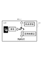
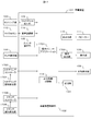
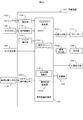
- FIG. 1 is a configuration diagram of an in-vehicle device 101 according to the first embodiment.
- the in-vehicle device control unit 102 is a part that controls the overall operation of the in-vehicle device 101, and performs an operation according to a program related to the messenger application 113 and the output information control unit 114 stored in the storage unit 123, thereby performing the messenger application 113 and the output.
- the function as the information control unit 114 is expressed.
- an application other than the messenger application 113 and the output information control unit 114 can be installed in the in-vehicle device 101, and these programs can be stored in the storage unit 123 at the time of shipment from the factory. It is also possible to store the data in the storage unit 123 by the user's selection through the unit 107 or an external connection IF (not shown) such as a USB terminal. Moreover, while controlling the basic operation as a car navigation system, the contents to be output are controlled based on various input information.
- the sensing unit 103 is a part that detects the distance between the user's hand and the sensor and the user's hand shake.
- an infrared distance sensor for example, an infrared distance sensor, a laser distance sensor, an ultrasonic distance sensor, a distance image sensor, an electrolytic sensor, an image sensor, etc.
- Sensor a microcomputer that performs data processing, and software that operates on the microcomputer.
- the sensor used for the sensing unit 103 is not particularly limited as long as it has a function for obtaining a signal obtained for detecting a distance to the user's hand and a hand shake.
- the gesture detection unit 104 Based on the sensor data obtained from the sensing unit 103, the gesture detection unit 104 detects whether or not a user's hand-holding and a predetermined gesture (for example, a hand gesture motion in the up / down / left / right direction) have been performed. For example, the hand-holding detects whether or not a predetermined sensor value has continued for a certain period of time, and the gesture operation detects the reaction time difference of the hand detection results among a plurality of sensors, respectively.
- a predetermined gesture for example, a hand gesture motion in the up / down / left / right direction
- the switch operation unit 105 is a hardware switch for operating the in-vehicle device 101, and a button press type or a jog dial type is mounted.
- the touch operation unit 106 transmits the touched coordinates to the in-vehicle device control unit 102 and operates the in-vehicle device 101.
- the microphone 115 acquires sound inside the vehicle.
- the speech recognition unit 116 converts speech from the input sound data into a character code string.
- the communication unit 107 connects to an external network and inputs / outputs various information. For example, input of information related to navigation, transmission / reception of messages, and the like.
- the external switch operation unit 117 is a switch operation unit installed at a location different from the in-vehicle device 101, and includes a steering switch installed near the steering wheel, a commander switch installed in the center console of the car, and the like.
- the display unit 108 is a device that presents video information to the user. For example, a display device such as an LCD (Liquid Crystal Display) and an arithmetic processing device necessary for display processing of video content or GUI (Graphical User Interface). And a device having a memory.
- the external display unit 109 is a display installed at a place in the vehicle different from the in-vehicle device 101, and displays an image.
- a head-up display (HUD) installed in front of the driver's seat can be used.
- the HUD can display various information while passing through the scenery in front of the driver (user).
- the sound output unit 110 is a part that outputs sound or sound.
- the speaker 111 outputs the sound from the sound output unit 110.
- the haptic IF output unit 112 is a part that transmits some tactile sensation information to the user.
- the haptic IF output unit 112 is configured by an ultrasonic array including a plurality of ultrasonic elements, and is pressured on a space at an arbitrary distance of the apparatus. Tell. Or you may provide a fan and provide the same effect.
- it may be comprised by the vibrator
- the messenger application 113 exchanges message data with the communication unit 107, and controls to store and output the input message. When transmitting a message, the transmission message is transmitted to the communication unit 107.
- the output information control unit 114 controls contents to be output to the display unit 108 or the external display unit 109.
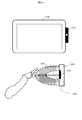
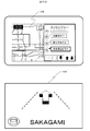
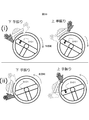
- FIG. 2A shows an installation example of the sensing unit 103. It is arranged on the driver side in the right-hand drive vehicle with respect to the display unit 108, and can detect the distance information of the object from the point of the sensor element and the movement of the object. As a result, as shown in the lower diagram in the figure, the space between the in-vehicle device 101 and the user is divided into a plurality of regions, and the region in which the user's hand exists is detected in detail. As shown in the figure, a distinction is made between an area 201 near the sensor position and an area 202 closer to the sensor position. The number of sensor elements, the installation position, and the detection area are not limited to this.
- the messenger application 113 When the messenger application 113 outputs video or audio information to the output unit such as the display unit 108, the external display unit 109, and the speaker 111, the messenger application 113 transmits the video or audio information to the output information control unit 114, and the output information control unit 114. In order to simplify the description, the messenger application 113 outputs video to the display unit 108 for the sake of simplicity. 113 uses an expression such as outputting sound.
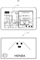
- the output information control unit 114 displays a display related to navigation and an icon 401 of the messenger application 113 on the display unit 108 (here, a center display) at the start of operation. Yes.
- the messenger application 113 is executed in the background by the in-vehicle device control unit 102 when the in-vehicle device 101 is activated, and the touch operation unit 106 detects a touch operation on the icon 401 or a user-specified gesture operation (for example, in front of the sensor).
- the gesture detection unit 104 detects a left hand gesture
- the output information control unit 114 activates the gesture.
- a display related to navigation and a display related to the messenger application 113 are displayed by the output information control unit 114.
- the messenger application 113 When a message is received from the outside via the communication unit 107 (S301), the messenger application 113 outputs a sound effect when the message arrives, and the total number of messages received on the external display unit 109 is indicated by the icon in FIG. A message 402 is displayed to inform the user that the number of unread messages has increased.
- FIG. 4C is a display example when the half screen of the display unit 108 is displayed as the messenger application 113.
- the messenger application 113 When the touch operation unit 106 detects a touch on the area of the icon 403 in FIG. 4C, the messenger application 113 starts from the left of the area of the icon 403, and returns a stamp reply / fixed sentence reply, free speech reply, message return / send, respectively. A display for performing each operation is displayed on the display unit 108. Further, the messenger application 113 displays the current number of unread messages and the name of the sender of the message being read out on the external display unit 109 as indicated by 404 in the lower diagram of FIG.
- the gesture detection unit 104 detects a prescribed gesture operation by the user (for example, an upward or downward hand gesture operation) while reading a message (S306: Yes)
- the messenger application 113 is the latest unread message.
- the voice information is output to the speaker 111 so as to read out the message (S308).
- the messenger application 113 continues to output voice information so as to read out the unread messages in order from the oldest (S307).
- the display unit 108 and the external display unit 109 display FIG. While the last sender is displayed as in d), a reply operation is waited (S309).
- the messenger application 113 displays an icon 501 indicating that a reply operation by a gesture is possible as shown in FIG.
- the operation start condition is determined to be satisfied, and the external display unit
- the display is switched to 109 so that the menu that is the operation guide for the reply operation is slid from the right side of the screen, and a sound effect in which the menu appears is output (S311).
- the messenger application 113 outputs a sound effect that informs the user so that it can be recognized by hearing, and an icon as shown in FIG. 5B. By moving 501 to the right or changing the color of the icon, notification may be performed so that it can be recognized visually.
- the messenger application 113 when a user's hand is detected not in the area 202 but in the area 201 and a certain time (for example, 0.3 seconds) elapses, the messenger application 113 generates a sound effect indicating that the position of the hand is different. Output.
- the messenger application 113 when the user holds the hand, the user can perform the hand-holding operation while looking at the front without sending the line of sight to the hand.
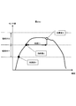
- FIG. 2B and FIG. 2C show the details of the relationship between the detection state of the user's hand and the sound effect output.
- FIGS. 2B and 2C show the time axis and the sensor values of the sensing unit 103, respectively, and are diagrams showing boundaries where the sensor values are determined to be regions 201 and 202.
- FIG. FIG. 2B shows an example in which the user extends his / her hand toward the area 202 and holds his / her hand for a certain period of time.
- the gesture detecting unit 104 detects that a hand has entered the area 201
- the sound effect 1 is output.
- sound effect 2 is output when it is detected that the user has entered the area 202.
- the sound effect 3 is output and the display on the external display unit 109 is switched as described for S311.
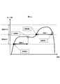
- FIG. 2C is an example in the case where the hand is continuously held over the area 201.
- the sound effect 1 is output.
- the hand 201 is continuously detected in the area 201 for a time T2 or longer (for example, 0.3 seconds or longer)
- the sound effect 4 is output.
- the operation is the same as in the example of FIG. 2B (hereinafter, an operation of holding the hand over the area 202 for a time T1 or more may be simply referred to as “hand holding”).
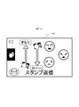
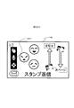
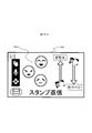
- FIG. 5C shows an example in which an operation menu capable of replying with a stamp is displayed.
- the icon 502 is an operation guide that means that when a hand is held up and a gesture of up / left / down is performed, a stamp corresponding to the gesture can be selected. Further, the display at the upper left half means the total number of displayed stamp candidates and the current page.
- the messenger application 113 selects a stamp corresponding to the direction and performs a reply operation (S313). Transition to the standby state S309.
- An icon 503 means a stamp candidate that can be currently selected.
- the icon 504 means that a corresponding operation is performed when a gesture operation corresponding to the displayed direction (an upward hand shake or a downward hand shake) is performed.
- the display of “standard text” switches the reply method to the standard text reply, and the display of “next page” switches the selection candidate of the stamp from the icon 503 to the next candidate group. Each means what you can do.
- the messenger application 113 deletes the operation guide from the display of the external display unit 109, A transition is made to the reply operation waiting state in S309 (S320).
- the messenger application 113 displays the content of the reply operation result (here, the selected stamp) on the display unit 108 and performs the reply operation on the external display unit 109 as shown in FIG. The user's name is displayed and the response is read aloud.
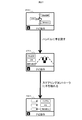
- FIG. 3B shows a simplified operation flow.
- the basic operation is as described above, and the description of the operation in each step is the same as that given the same step number in FIG. 3A, but with respect to S316 in this figure, the vertical direction is the same. Not only hand gestures but also various operations such as an operation with a steering switch may be accepted.
- a message when a message is received from the outside, it may be configured such that it is read out simultaneously with the reception, and the content of the received message may be displayed on the external display unit 109. This makes it easier for the user to grasp the message.
- the reply operation may be accepted at any time without waiting for the latest message to be read. Thus, the user can perform a reply operation at any time.
- a pressure point of the ultrasonic element array appears on the boundary of the region, or a tactile sensation is given on the vertical line of the region by a blower.
- the state transits to the stamp reply operation state, but before that, it may be configured to transit to the reply method selection state (stamp, fixed phrase, free utterance, etc.) good. Thereby, the user can select the reply method he / she wants to perform at the start of the reply operation.
- a hand is detected and an operation guide is displayed on the external display unit 109, and then a gesture is accepted.
- a predetermined time before the operation guide is displayed for example, 0.2 seconds before
- S319 the passage of a certain time is measured. If a predetermined operation (for example, a left hand gesture operation or a switch operation) is detected before satisfying this condition, the process proceeds to S320. It is good also as a structure. Thereby, the display of the external display unit 109 can be switched for navigation at a timing that the user likes.
- a predetermined operation for example, a left hand gesture operation or a switch operation
- the operation guide and the gesture direction displayed on the external display unit 109 are not limited to three directions, and any direction and number may be used. In that case, it is preferable to set a direction in which a gesture operation can be easily performed while sitting in the driver's seat. For example, a gesture performed toward the handle direction is not targeted because the hand may hit the handle during the operation.
- a gesture performed toward the handle direction is not targeted because the hand may hit the handle during the operation.
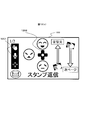
- the handle of the vehicle to be boarded is the right handle or the left handle can be set in advance on the setting screen, and when it is the left handle, it is displayed on the external display unit 109 as shown in FIGS.
- the operation guide to be recognized is the recognition target in the three directions of up, down, and right.
- FIGS. 7A and 7B correspond to FIGS. 5C and 5D, respectively.
- the hand used for the gesture will change, so the icon display and orientation will also change. Furthermore, since the appearance of various icons changes depending on the position of the handle, the user may be able to make settings individually. As a result, it becomes possible to perform an operation with an easy-to-use gesture operation according to the handle installation position for each vehicle type, and it becomes possible for the user to perform various operations with a gesture without difficulty while sitting in the driver's seat.
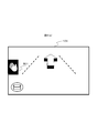
- the position where the hand is held is not limited to one place, and the hand may be held at a plurality of places.
- the hand may be held at a plurality of places.
- the reply method may be determined depending on which sensor is placed over the hand.
- the sensor 103A is a stamp reply
- the sensor 103B is a fixed sentence reply
- the sensor 103C is a free utterance reply.
- the user can quickly select a reply method and perform a reply operation. It may be possible for the user to specify in advance which sensor corresponds to which method.
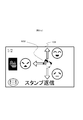
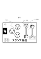
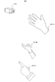
- FIG. 9 it is good also as a structure which detects a hand approach and a gesture using a camera for the sensing part 103.
- FIG. 9 A predetermined hand-shaped image is learned in advance, and the user's hand-holding is detected regardless of the distance and position from pattern recognition between the input video image and the learning data.
- a plurality of hand shapes when the hand is held up may be detected (901A to 903C), and a reply method may be selected.
- the user can start a reply operation without reaching the front of the sensing unit 103 and performing a gesture operation.
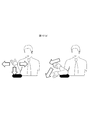
- the direction and number of gestures to be accepted may be changed according to the position and posture of the user's hand when detecting a hand hold. For example, as shown in FIG. 10 (a), when the user raises his / her hand with the elbow placed on the armrest and detects a hand hold, as shown in FIG. 10 (b), the left / bottom / right The direction is the recognition target. This is because it is considered difficult to perform an upward gesture in the user's posture in this situation, and these three directions are set as recognition targets. Furthermore, the user may include an arrangement can be set whether to which the gesture recognition target in advance. As a result, the user can perform gesture operations in a free posture.
- the operation menu for the reply operation is displayed on the external display unit 109.
- the display location and the display contents are changed according to the connection state and installation position of various devices. It is also good.
- a gesture operation guide is displayed on the center display as shown in FIG.
- the installation positions and connection states of the plurality of displays are managed, and the priority is determined.
- an operation guide is displayed on a display with a high priority, but when it cannot be used, such as when the HUD breaks down, it is displayed on the display with the next priority. In this case, the guide display time may be shortened or the amount of information displayed may be reduced according to the priority.
- the priority is set in the in-vehicle terminal so that the priority is determined based on the nature of the display connected to the in-vehicle terminal, which is set at the time of shipment from the factory or at the time of sale, set by the user on a setting screen (not shown) It can be set by a method such as
- the priority may be increased according to the installation position. Accordingly, when a device that is assumed to display an operation guide such as a HUD cannot be used, the operation guide can be displayed on an alternative display and operated.
- FIG. 12A shows an operation flow at that time.
- S316 when a preparatory operation for performing a certain operation means is detected (S1201: Yes), an operation guide corresponding to the operation is displayed on the external display unit 109 (S1202).
- S1203: Yes Thereafter, when a selection operation is executed (S1203: Yes), a reply is made with the selected option (S1204).
- an operation guide as shown in FIG. 12B is displayed on the external display unit 109 when transitioning to the state of S315.
- the icon 1201 indicates that the upper icon can select an option by gesture, the middle icon can select an option by speech recognition, and the lower icon can select an option by a switch.
- FIG. Transition to a screen like An icon 1201 notifies that the steering operation is active by changing the icon color.
- stamp candidates corresponding to the buttons of the stacon are displayed.
- a reply operation is performed with a corresponding stamp according to the button of the pressed button. Note that if the fixed time has elapsed or the contact sensor of the stacon stops responding, the screen returns to the screen of FIG.
- a transition is made to a screen as shown in FIG.
- An icon 1201 indicates that speech recognition is in a standby state, and a display 1203 indicates that a utterance corresponding to each character is performed, and a stamp corresponding to the character can be selected. If the result of voice recognition matches any of the options, a corresponding stamp reply operation is performed. In the example of FIG. 12D, only characters corresponding to icons such as “fun” are displayed, but by displaying the transmitted icons side by side with the characters, the transmitted icons can be seen at a glance. Also good. If the voice recognition is used, the user can select a stamp to be transmitted without releasing his / her hand from the handle, which can contribute to further safe driving.
- the three types of operation means can be switched in the middle of any operation if a start trigger of each operation is detected.
- a gesture operation by a vertical hand gesture is accepted in that state.
- the reply operation means can be freely selected according to the driving situation and according to the user's preference without being limited to one operation means.
- each operation means is switched, by presenting which operation means can be operated at present and how to perform the operation, the user can quickly and intuitively understand the operation. The operation can be performed.
- FIG. 12 (e) presents navigation-related operations such as route setting to the home, location registration of the current location, and destination setting by voice as selection candidates when there is no application running in the background other than navigation. This is an example.
- FIG. 12F shows an example in which music stop, operation to skip to the next song, or skip to the previous song, etc. are presented as selection candidates when a hand is held during music playback or the like.
- FIG. 12G is an example in which when listening to traffic information or the like, when holding the hand, an operation for listening to details of the traffic information, reroute, destination change, etc. are presented as selection candidates.
- various operations can be quickly selected in accordance with the status of the application controlled by the in-vehicle device 101 being driven by the user.
- the in-vehicle device 101 allows the user to operate intuitively and quickly while looking forward while driving. Specifically, you can quickly switch the display of the messenger application, skip messages, etc. while looking forward. Further, in the case of an operation for selecting a plurality of options, it is possible to select a desired option while confirming the contents of the selection candidates while looking at the forward direction. Furthermore, when familiar with the operation, the options can be operated without looking at the display, so that the operation can be performed more safely and quickly.
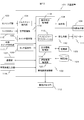
- FIG. 13 is a configuration diagram of the in-vehicle device 101 according to the second embodiment.
- a vehicle information input unit 118, an operation means control unit 119, a driving load estimation unit 120, and a map DB (database) 121 are added.
- the vehicle information input unit 118, the operation unit control unit 119, and the driving load estimation unit 120 are also operated by the in-vehicle device control unit 102 according to the program stored in the storage unit 123, so that the vehicle information input unit 118, the operation unit control unit 119, the function as the driving load estimation unit 120 is expressed.
- the vehicle information input unit 118 is a part that acquires information related to a running vehicle.
- the vehicle information input unit 118 is connected to the vehicle via a CAN (Control Area Network), and the vehicle speed, accelerator opening, brake depth, blinker signal, steering angle, etc. Get etc.
- the operation means control unit 119 controls to which operation the operation input from the gesture detection unit 104, the voice recognition unit 116, and various switch operation units is reflected.
- the driving load estimation unit 120 estimates how much the user's driving load in driving operation is. For example, in addition to the various input signals from the vehicle information input unit 118 described above, information input from the communication unit 107 (map information, type of road on which the vehicle is traveling, distance to the preceding vehicle, etc.) is integrated, and the driving load Define levels in four levels (none, low, medium and high). “None” is a straight line with no obstacles in the vicinity, such as when the vehicle is stopped without waiting for a signal, or when the driver is driving without any special operation such as ACC (Adaptive Cruise Control). When driving on roads, “medium” is at a certain speed or higher, driving situations that require steering operation at all times, or when turning left or right at intersections. Situation, etc.
- the map DB 121 is a database that stores map information.
- the operation of the in-vehicle device 101 according to the second embodiment will be described in detail.
- the basic operation is the same as that described in the first embodiment, and the second embodiment is characterized in that the operation is controlled according to the output of the driving load estimation unit 120.
- the in-vehicle device control unit 102 defines in advance the driving load level output from the driving load estimation unit 120, the operation means that can be operated at that time, and the display contents that can be presented.
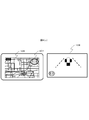
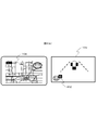
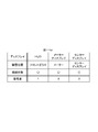
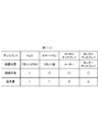
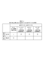
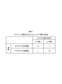
- FIGS. 14A to 14D show the definitions.
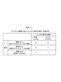
- FIG. 14A shows whether or not each operation means can be used at each operation load level.
- the driving load level is “none” or “low”
- a reply operation can be performed by all the operation means described in the first embodiment.
- the driving load level is “high”
- all operations are prohibited.
- the driving load is “medium”
- display of an operation guide by hand-holding and subsequent selection of an option by gesture operation are prohibited. This is because the operation with a hand-hold is an operation means forcing one-handed operation, and this operation is prohibited in a situation where the user should concentrate on the driving operation.
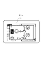
- the current operating load level is displayed as shown by an icon 1503 in FIG.
- This figure means a state where the driving load level is “medium”, and an icon 1501 indicates that the operation by the hand holding is prohibited as an icon 1501.
- the icon 1501 is emphasized by changing the display or color, and a warning sound or a warning sound is output to immediately stop holding the hand. Prompt.
- the user can grasp the current driving load situation and keep one hand away from the handle for a long time in an attempt to display the operation guide even when the handle operation is necessary. It can be prevented as much as possible.
- a direct utterance reply by voice recognition without using a hand or a direct gesture completed by a momentary operation can be used even in a situation where the driving load level is “medium”.
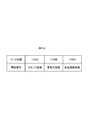
- FIG. 14 (b) is a definition regarding the operation load level and the output content of the center display.
- the messenger application 113 displays all the text of the message.
- a reply operation is performed from a basic operation such as touching an operation icon on the screen, all options such as a stamp candidate are also displayed.
- the driving load is “low” or “medium”
- the message text is not displayed and only the name of the message sender is displayed. Also, the operation system is not displayed using the touch operation.
- the driving load is “high”
- the screen of the messenger application 113 is also turned off, and a warning message corresponding to the situation (for example, “Warning!”) Is displayed.
- the driving load is “Low” or “Medium”
- the operating load level changes to “None” while performing a reply operation by holding the hand, it is displayed on the HUD.
- the operation can be performed even by a touch operation on the center display. For example, as shown in FIG. 16 (a), assuming that the stamp has been returned on the HUD, the center display as shown in FIG. Also displayed.
- the content is displayed on the center display like 1602 while maintaining the contents of the stamp candidate 1601 on the HUD and the arrangement relationship on the screen. Further, the contents of 1602 are arranged close to the driver side so that the driver can easily operate, and the stamp can be selected by a touch operation. Further, the remaining stamp candidates are arranged at positions far from the driver side on the screen as 1603.
- the driving load is switched to “Low” or “Medium” due to the start of the car while the operation is being performed on the center display while the vehicle is stopped, the display and selection of options on the center display Is stopped, the reply method that was in the middle of the operation is retained, the process proceeds to step S315 in FIG. 3A, and the operation is directly taken over.
- FIG. 14 (c) is a definition regarding the operation load level and the output contents of the HUD.
- the driving load level is “none” or “low”
- the name of the sender at the time of reading a message is displayed, and the operation guide at the time of reply operation is displayed.
- the driving load level is “medium”, it is displayed that the operation by hand-holding is prohibited or the operation guide display is taken over only when the driving load level is changed from “low” to “medium”. indicate.
- the driving load level is “high”, a warning message corresponding to the situation (for example, “attention between vehicles!”) Is displayed.
- FIG. 14 (d) is a definition regarding the driving load level and the sound output from the speaker.
- the driving load level is “None” to “Medium”, an operation sound or a reading voice at that time is output.
- the driving load level is “high”, only a warning sound is output. Even if the message is read out, the output is stopped. The stopped read-out message is resumed after the driving load level is lowered, and read again from the head of the message.
- the hand-holding detection algorithm which is designed to be able to operate quickly and without moving the line of sight from the front, allows touch operations and side-views to be permitted when stopped. It is possible to prevent erroneous detection due to an operation other than the operation.
- the user can operate intuitively and quickly while looking forward while driving, as well as a margin for stopping, etc.
- you can receive operations by a variety of means and a large amount of information, and in situations where you should concentrate on driving operations, other operations may focus attention other than driving operations Can be prevented and safe driving can be performed.
- the in-vehicle device has been described as an example.
- the present invention is not limited to this, and includes a display unit and an operation unit such as a personal computer, a digital signage, a construction machine, an aircraft, and a monitoring operator device. Can be applied.
- FIG. 17 is a configuration diagram of the in-vehicle device 101 according to the third embodiment. Compared to the configuration diagram of FIG. 1, an operation menu application 1701, a display output unit 1702, a steering controller 1703, a steering contact detection unit 1704, a commander controller 1705, and a commander contact detection unit 1706 are added.
- the operation menu application 1701 is software that displays an operation menu on the display unit 108 and the external display unit 109 in accordance with a program stored in the storage unit 123.
- the display output unit 1702 has a function of outputting a video signal to the display unit 108 when a display device that is not built in the in-vehicle device 101 is used as the display unit 108.
- the steering controller 1703 is a switch component provided in the steering and is used by the user to input an operation.
- the steering contact detection unit 1704 detects whether the user's hand is touching the switch part of the steering controller 1703.
- the commander controller 1705 is a switch component provided in an instrument panel or a center console in the vehicle, and is used for a user to input an operation.
- the commander contact detection unit 1706 detects whether the user's hand is touching the switch part of the commander controller 1705.
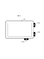
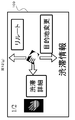
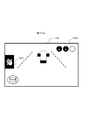
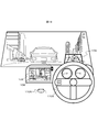
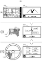
- FIG. 18 shows the appearance of the cockpit in the third embodiment.
- the display unit 108 is installed at the center of the instrument panel, and can be touched by the touch operation unit 106.
- a sensing unit 103 for detecting a gesture is provided on the upper right of the display unit 108.
- the external display unit 109 uses a HUD, and can display various information while passing through the scenery in front of the driver (user).
- a steering controller 1703 is provided in the steering.
- a commander controller 1705 is provided on the center console.
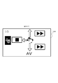
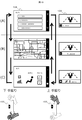
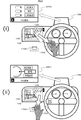
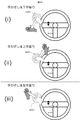
- FIG. 19 shows how the display contents of the display unit 108 and the external display unit 109 are changed by the upward and downward hand movements with respect to the sensing unit 103.
- Each display of (A), (B), and (C) of FIG. 19 shows a display in a screen mode controlled by the operation menu application 1701, (A) is an audio operation mode, and (B) is a navigation operation. Mode (C) is an air conditioner operation mode.
- Mode (C) is an air conditioner operation mode.
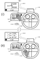
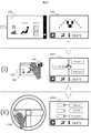
- FIG. 20 shows a state where the gesture and the steering controller 1703 are operated in the (B) navigation operation mode.
- a gesture operation menu 2001 is displayed on the external display unit 109. By moving the hand in one direction, it is guided that an item corresponding to the direction is selected.
- a steering controller operation menu 2002 is displayed as shown in FIG. 20 (ii).
- pressing one of the upper, middle, and lower switches of the steering controller 1703 guides selection of an item corresponding to the switch.
- the state of (ii) of FIG. 20 if the user puts his hand over the sensing unit 103 again without pressing any switch, the state of (i) of FIG. 20 is obtained.
- FIG. 21, FIG. 22, and FIG. 23 show screen transitions of the external display unit 109 in the series of operations described in FIG. 19 and FIG.
- FIG. 21 shows screen transitions in the (B) navigation operation mode
- FIG. 22 shows the (A) audio operation mode
- FIG. 23 shows (C) the air conditioner operation mode.
- FIG. 24 shows the details of the movement in the screen of the external display unit 109 in the (B) navigation operation mode.
- the gesture operation menu 2001 is displayed on the external display unit 109.
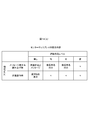
- FIG. 26A is a table showing the correspondence between gesture detection states and operation devices in the in-vehicle device 101 of the third embodiment.
- FIG. 26C is a table showing the correspondence between operation devices and display devices according to the running and stop states.
- the output information control unit 114 according to the third embodiment determines an operation device and a display device used for an operation of a predetermined menu according to FIGS. 26 (a) and 26 (c).
- the output information control unit 114 determines that the user is about to operate with a gesture.
- the hand is away from the sensing unit 103, it is determined that the user is about to operate with the steering controller 1703.
- the output information control unit 114 instructs the operation menu application 1701 to output a predetermined screen.
- the output information control unit 114 determines that the user is about to perform an operation using the gesture and steering controller 1703 and the commander controller 1705 when the vehicle is running. At that time, an operation menu is displayed on the HUD which is the external display unit 109. As a result, the user can visually recognize the operation menu with little line-of-sight movement from the state of visually confirming the front of the vehicle, and thus an effect of suppressing the influence on the driving operation by operating the operation menu is obtained.
- the steering controller operation menu 2002 when the user returns his hand to the steering wheel, the steering controller operation menu 2002 is displayed on the external display unit 109, but when the user tries to perform a driving operation with his hand returned to the steering wheel. It may be considered that the display of the steering controller operation menu 2002 is troublesome. Therefore, as shown in FIG. 27, when the user returns his hand to the steering wheel, a simple menu is displayed in which the menu display portion is reduced in the external display unit 109 as shown in 2701 of FIG. When the steering contact detection unit 1704 detects that the user touches the switch of the steering controller 1703, the steering controller operation menu 2002 may be displayed.
- the steering controller operation menu 2002 is not displayed until just before the user operates the steering controller 1703, so that the troublesomeness of the menu display can be reduced, and the display on the external display unit 109 can be replaced with other information necessary for driving.
- the effect that it can be effectively used for the display of is obtained.
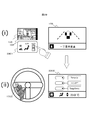
- FIG. 28 shows the external appearance of the operation of the in-vehicle device 101 in the fourth embodiment.
- a state in which a commander operation menu 2801 is displayed on the external display unit 109 when the user brings his hand close to the commander controller 1705 is added.
- a camera is used for the sensing unit 103 as shown in FIG.
- the sensing unit 103 according to the fourth embodiment detects in which direction the user's hand is moving around the sensing unit 103.
- the sensing unit 103 may be a sensing device other than a camera as long as the direction in which the user's hand is moving can be detected.
- FIG. 28 shows a state in which the gesture and operation by the steering controller 1703 and the commander controller 1705 are performed in the (B) navigation operation mode.
- a steering controller operation menu 2002 is displayed as shown in (i) of FIG. Is done.
- an operation menu 2801 is displayed. In the state of (ii) of FIG. 28, it is guided that one item is selected by rotating the rotary controller corresponding to the rotary controller mounted on the commander controller 1705.
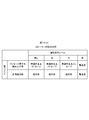
- FIG. 26B is a table showing selection of operation devices according to the position and movement direction of the hand in the in-vehicle device 101 according to the fourth embodiment.
- the output information control unit 114 according to the fourth embodiment determines an operation device to be used for a predetermined menu operation according to FIG. As illustrated in FIG. 26B, when the hand is near the sensing unit 103, the output information control unit 114 determines that the user is about to operate with a gesture. When the user's hand moves from the sensing unit 103 to the direction or position of the steering controller 1703, it is determined that the user is about to operate with the steering controller 1703.
- the output information control unit 114 instructs the operation menu application 1701 to output a predetermined screen. As a result, it is possible to display an operation menu and an operation guide suitable for the operation device that the user intends to operate, and an effect that the user can smoothly perform an operation using a desired operation device is obtained.
- the operation menu when displaying the operation menu, it may be based on the pointing direction of the user detected by the sensing unit 103 instead of based on the direction or position of the user's hand moving from the sensing unit 103.
- the sensing unit 103 detects that the user points to the air conditioner operation panel 2901, and based on this, the external display unit 109 is used for air conditioner operation.
- a steering controller operation menu 2302 may be displayed. Thereby, an effect that a desired operation menu can be displayed more smoothly without the user once holding the hand over the sensing unit 103 is obtained.
- FIG. 30 is a configuration diagram of the in-vehicle device 101 according to the fifth embodiment. Compared to the configuration diagrams of FIGS. 13 and 17, a steering operation detection unit 3001, a driving situation recognition unit 3002, and a gesture control unit 3003 are added.
- the driving situation recognition unit 3002 and the gesture control unit 3003 represent functions realized by executing the program stored in the storage unit 123 by the in-vehicle device control unit 102 as function blocks.
- the steering operation detection unit 3001 detects the steering operation status by the user based on the steering angle information acquired by the vehicle information input unit 118 and outputs the detected steering operation status to the driving status recognition unit 3002.
- the driving situation recognition unit 3002 detects the driving situation of the vehicle based on the output of the steering operation detection unit 3001. When the driving situation recognition unit 3002 determines that the driving situation of the vehicle is in a predetermined state to be described later, it outputs a gesture operation invalidation command to the gesture control unit 3003.
- the gesture control unit 3003 normally outputs the input from the gesture detection unit 104 to the operation menu application 1701 so that the operation based on the gesture is valid.
- the gesture control unit 3003 discards the input from the gesture detection unit 104 and invalidates it, and makes the operation based on the gesture invalid.
- the gesture control unit 3003 may stop the operation of the gesture detection unit 104, that is, stop the gesture detection by the gesture detection unit 104 when the driving condition recognition unit 3002 outputs an invalidation command.
- FIG. 31 is a view showing the appearance of the cockpit in the present embodiment.
- a sensing unit 3101 for detecting a gesture is provided on the left side in the steering of the right-hand drive vehicle. Similar to the sensing unit 103 described in the first to fourth embodiments, the sensing unit 3101 is a part that detects the distance between the user's hand and the sensor and the user's hand shake.
- the external display unit 109 uses a HUD, and can display various information while passing through the scenery in front of the driver (user).
- the display unit 108 is installed at the center of the instrument panel and can be touched by the touch operation unit 106.
- Display corresponding to the gesture operation detected by the sensing unit 3101 is performed on the display unit 108 or the external display unit 109.
- the output information control unit 114 shown in FIG. 30 instructs the operation menu application 1701 to output a predetermined screen
- the operation menu related to the gesture operation is displayed on the display unit 108 or the external display unit 109.
- the operation menu application 1701 is software that displays an operation menu on the display unit 108 and the external display unit 109 in accordance with a program stored in the storage unit 123.
- the installation position of the sensing unit 3101 is changed from the sensing unit 103 shown in FIG. 2 and the like.
- the gesture detection area that is in the vicinity of the display unit 108 is the steering.
- To the left of The display unit 108 is displayed in accordance with the display content of the display unit 108 or the external display unit 109 being changed by a gesture such as upward or downward in the vicinity of the left side of the steering and the steering angle detected by the steering operation detection unit 3001.
- it is characterized in controlling whether to change the operation menu and operation guide displayed on the external display unit 109, that is, whether to accept the user's gesture operation as valid.
- the user can perform a gesture operation with a small movement in the vicinity of the steering wheel without releasing a large hand from the steering wheel while driving, and at the same time, the gesture operation is switched between valid / invalid depending on the steering angle.
- the steering operation detection part 3001 demonstrated the example which detects the operation condition of steering based on information, such as a steering angle which the vehicle information input part 118 acquired, it is not restricted to this, A steering angle is used using a camera or a sensor.
- the configuration may be such that the steering operation of the user is detected.
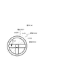
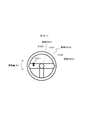
- a gesture detection area 3201 in FIG. 32 and FIG. 33 is an area in which the sensing unit 3101 visualizes an area where a user's hand movement is detected. As described above, in the present embodiment, the gesture detection area 3201 is set near the left side of the steering wheel, and the user performs a gesture operation with the left hand.
- FIG. 32 (i) shows a gesture operation of a hand movement in which the hand moves across the gesture detection area 3201 from the top to the bottom without stopping the hand in the gesture detection area 3201.
- FIG. 32 (ii) shows a gesture operation for moving the hand so as to cross the gesture detection area 3201 from below without stopping the hand in the gesture detection area 3201.
- these two gesture operations are collectively referred to as “direct gesture”.
- FIG. 33 shows a gesture operation method of moving a hand after a hand hold that temporarily stops the hand in the gesture detection area 3201, and this is referred to as a “hand hold gesture” in the present embodiment.
- a gesture operation menu 2001 as shown in FIG. 20 (i) is displayed on the external display unit 109.
- an item corresponding to the direction is selected by moving the hand in the downward, upward, or left direction from the position where the user holds the hand.
- “Destination setting” is selected.
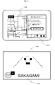
- FIG. 34 is a diagram illustrating an example of an operation using the direct gesture of FIG. 32, and shows that processing for the gesture operation changes according to the steering angle of the steering.
- FIG. 34 (i) shows a state where the steering operation detection unit 3001 detects that the steering is hardly turned, that is, a state where the steering angle 3410 is almost zero. In this state, when a downward hand gesture with respect to the gesture detection area 3201 is detected, the display content of the display unit 108 is changed from the audio operation mode to the air conditioner by the operation of the operation menu application 1701 according to the control of the output information control unit 114. Switch to operation mode.
- FIG. 34 (ii) shows a state where the steering angle 3411 is not zero, that is, a state where the steering is being turned.
- the gesture control unit 3003 performs control to invalidate the user's gesture operation detected by the gesture detection unit 104.
- the output information control unit 114 displays the operation menu related to the gesture operation as described above even when the downward gesture with respect to the gesture detection area 3201 is detected. Control for displaying on the external display unit 109 is not executed.
- the display content of the display unit 108 shown in the lower right of FIG. 34 (ii) remains in the audio operation mode, indicating that the gesture operation has been invalidated.
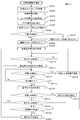
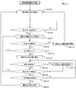
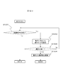
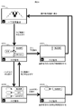
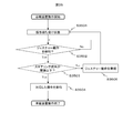
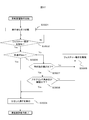
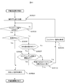
- FIG. 35 is a flowchart showing the operation of the in-vehicle device 101.
- the in-vehicle device 101 executes a program whose operation is represented by FIG.
- step S3501 the gesture detection unit 104 starts waiting for input from the user, and proceeds to step S3502.
- step S3502 it is determined whether or not the gesture detection unit 104 has detected a gesture operation. If it is determined that the gesture operation has been detected, the process proceeds to step S3503. If it is determined that the gesture operation has not been detected, the process proceeds to step S3502.
- the gesture operation in this step is the above-described direct gesture or hand-holding gesture.
- step S3503 the driving situation recognition unit 3002 determines whether the steering angle is equal to or less than a predetermined threshold based on information from the steering operation detection unit 3001. This threshold value is stored in the storage unit 123. If it is determined that the steering angle is equal to or less than the threshold, the process proceeds to step S3504. If it is determined that the steering angle is greater than the threshold, the process proceeds to step S3505.
- step S3504 the output information control unit 114 and the operation menu application 1701 execute processing corresponding to the gesture operation detected in step S3502, and the program whose operation is represented in FIG.
- the process corresponding to the gesture operation is, for example, transition of the display unit 108 or the external display unit 109 shown in FIG. 34 (i) or execution of a selection operation.
- step S3505 the driving situation recognition unit 3002 outputs an invalidation command for invalidating the gesture operation to the gesture control unit 3003.
- the gesture control unit 3003 invalidates the gesture operation by invalidating the input from the gesture detection unit 104 or stopping the operation of the gesture detection unit 104 as described above. . Thereafter, the process returns to step S3501.
- step S3504 is executed for the first time. Is done.
- the output information control unit 114 causes the display unit 108 or the external display unit 109 to display a gesture operation menu indicating a gesture operation candidate corresponding to the movement of the user's hand after the hand is held over. .
- a gesture operation menu 2001 as shown in FIG. 20 (i) is displayed on the external display unit 109.
- step S3504 is executed again, so that the gesture is supported according to the gesture operation menu displayed on the display unit 108 or the external display unit 109. Is performed.
- step S3505 is executed and the gesture operation is invalidated.
- the output information control unit 114 does not display the gesture operation menu as described above on the display unit 108 or the external display unit 109 because step S3504 is not executed.
- the output information control unit 114 does not change the display content of the display unit 108 or the external display unit 109. After that, even if the user performs a hand movement operation to move the hand held over, the gesture operation corresponding to the hand movement is not executed.
- step S3502 after gesture detection is performed in step S3502, the gesture operation detected in step S3505 is ignored, and the gesture recognition result is not reflected in the function operation, thereby invalidating the gesture operation.
- the gesture operation may be invalidated by invalidating the gesture recognition function itself without performing gesture detection by the gesture detection unit 104.
- the in-vehicle device 101 includes a gesture detection unit 104 that recognizes the position of a user's hand in a predetermined gesture detection region 3201, a driving situation recognition unit 3002 that detects a driving situation of the vehicle, and a gesture detection unit 104.
- a gesture control unit 3003 for controlling the state of the gesture operation based on the recognition result of the hand position.
- the gesture control unit 3003 invalidates the gesture operation when the driving situation of the vehicle detected by the driving situation recognition unit 3002 is the invalidation target state. Since the in-vehicle device 101 is configured as described above, the gesture operation is invalidated based on the driving state of the vehicle, and the safety and operability of the operation of the in-vehicle device by the driver during driving can be improved.
- the in-vehicle device 101 includes a steering operation detection unit 3001 that detects a steering operation for driving the vehicle, and an output information control that controls display contents of the display unit 108 or the external display unit 109 connected to the in-vehicle device 101.
- the driving situation recognition unit 3002 detects the driving situation of the vehicle based on the steering operation.
- the invalidation target state is a state in which the steering operation amount of the user detected by the steering operation detection unit 3001, that is, the steering angle exceeds a predetermined threshold, that is, a prescribed operation amount.
- the output information control unit 114 does not change the display on the display unit 108 or the external display unit 109 even when the position of the user's hand is in the gesture detection area 3201. For this reason, if the steering operation amount exceeds a predetermined operation amount, the display on the display unit 108 or the external display unit 109 is not transitioned even if a direct gesture is performed. It will not be disturbed.
- the output information control unit 114 detects that the user has held the hand in the gesture detection area 3201, and the gesture detection unit 104 detects that the user's hand is held in step S3504.
- a gesture operation menu 2001 as shown in FIG. 20 (i) showing the gesture operation candidates corresponding to the above operation is displayed on the display unit 108 or the external display unit 109.
- the output information control unit 114 does not display the gesture operation menu 2001 on the display unit 108 or the external display unit 109.
- the gesture operation menu is not displayed on the display unit 108 or the external display unit 109 even if a hand-holding gesture is performed, and the gesture operation is not accepted.
- the user can be made aware.
- the in-vehicle device 101 includes a steering operation detection unit 3001 that detects a steering operation for driving the vehicle.
- the invalidation target state is a state in which the steering operation amount of the user detected by the steering operation detection unit 3001 exceeds a predetermined threshold, that is, a prescribed operation amount.
- the gesture control unit 3003 invalidates the gesture operation by stopping the operation of the gesture detection unit 104 or invalidating the input from the gesture detection unit 104.
- the steering angle exceeds the threshold value, it is considered that the user is turning the steering wheel to perform the driving operation. That is, there is a high possibility that the hand is moved for driving operation near the steering.
- the steering operation amount is an angle of steering operated by the user.
- the driving situation recognition unit 3002 evaluates the steering angle, that is, the steering angle, based on the output of the steering operation detection unit 3001.
- the steering operation speed that is, the steering angular speed may be evaluated. That is, in step S3503 in FIG. 35, it may be determined whether the steering angular velocity, that is, the steering operation speed is equal to or less than a predetermined threshold value. According to this modification, in addition to the operational effects of the fifth embodiment, the following operational effects are obtained.
- the steering operation amount is an operation speed of the steering operated by the user.
- the state where the steering angular velocity is almost zero is a state where the steering angle remains constant, and the user turns the steering a certain amount to perform driving operation, but slowly turns a curve with a large curvature. It is considered that the amount of operation with respect to the steering is small. In such a case, it is considered that the user can afford to perform an operation other than the driving operation regardless of the size of the steering angle. Therefore, by enabling the gesture operation, the gesture operation is performed in more cases. It can be performed and usability can be improved.
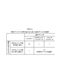
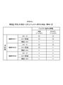
- FIG. 36 (a) is a diagram illustrating an example in which the steering angle in the steering operation is defined as a plurality of regions.
- a region between the steering angle SA00 and the steering angle SA01 is set as a region 3601, where the steering wheel is slightly turned. 3603.
- the area division is not limited to this, and the area may be divided more finely.
- FIG. 36B is a diagram illustrating the correspondence between the steering angle and the validity / invalidity of the gesture operation.
- the gesture control unit 3003 determines which gesture operation type is to be validated among a plurality of gesture operations according to the steering angle in accordance with FIG. For example, when the steering angle is in the region 3601, the gesture control unit 3003 validates both the direct gesture shown in FIG. 32 and the hand-holding gesture shown in FIG. This is because the steering angle for driving is not so much performed because the steering angle is small, and the hand movement performed in the gesture detection area 3201 near the steering is performed by the user for the gesture operation. It is possible.
- the gesture control unit 3003 invalidates both the direct gesture and the hand-holding gesture. This is because the steering angle is large, so the user concentrates on the steering operation for driving, and the possibility of performing the gesture operation is low, and the steering operation performed by the user for driving is erroneously recognized as a gesture operation. It is intended to prevent that.
- the gesture control unit 3003 validates only the direct gesture and invalidates the hand-holding gesture. This is because the characteristics of how to move the hand in direct gesture and hand-holding gesture are considered. While direct gestures end with a short hand gesture, hand-holding gestures move the hand over the gesture detection area 3201 for a certain period of time to perform the operation, so there is little steering operation for driving, and device operation It is suitable for performing when there is a relatively large margin. For this reason, considering the amount of work required for the steering operation for driving, it is determined that the user is unlikely to perform a hand-hold gesture when the amount of work is large, and the hand-hold gesture is controlled to be invalid.
- control is not limited to this, and for example, the determination may be made using only the region 3601 and the region 3603 or may be divided into four or more regions.
- the gesture control unit 3003 invalidates only a specific gesture operation from a plurality of gesture operations performed by the user based on the steering operation amount. Therefore, the gesture operation accepted according to the steering operation amount can be limited.
- the driving situation recognition unit 3002 increases gesture operations that are invalidated when the steering operation amount increases. For this reason, it is possible to reduce the number of gesture operations that are accepted as the user is less likely to perform a gesture operation and the possibility that a steering operation for driving is mistaken as a gesture operation is higher. Further, it is possible to perform fine gesture recognition processing with few false recognitions by controlling whether to accept the gesture operation of the user as valid by using the steering operation amount recognized by the driving situation recognition unit 3002 in a composite manner. It becomes possible.
- the configuration of the in-vehicle device 101 in the sixth embodiment is the same as that of the fifth embodiment. However, the operation of the vehicle device control unit 102 is different from that of the fifth embodiment.
- the driving status recognition unit 3002 is based on not only the steering operation status output from the steering operation detection unit 3001 but also information such as the vehicle speed, the accelerator opening, the winker signal based on the operation of the direction indicator, and the like acquired by the vehicle information input unit 118. , Recognize the driving situation.
- the driving situation to be recognized includes, for example, a state where the blinker signal is ON and the vehicle speed is zero, that is, a state where the vehicle is stopped, a state where the steering is turned rightward during traveling, and the like.
- the operation of the in-vehicle device 101 in the sixth embodiment will be described.
- the basic operation is the same as that described in the fifth embodiment.
- the operation speed of the steering by the user recognized by the driving situation recognition unit 3002 (for example, it is characterized by controlling whether or not a user's gesture operation is accepted as valid in accordance with on / off of a blinker signal (direction indicator), vehicle speed, and the like.
- FIG. 37 is a flowchart showing the operation of the in-vehicle device 101 according to the sixth embodiment.
- the same steps as those in FIG. 35 in the fifth embodiment are denoted by the same step numbers, and the description thereof is omitted.
- step S3501 the gesture detection unit 104 starts waiting for input from the user, and proceeds to step S3502.
- step S3502 it is determined whether or not the gesture detection unit 104 has detected a gesture motion. If it is determined that the gesture has been detected, the process proceeds to step S3506. If it is determined that the gesture has not been detected, the process remains in step S3502.
- step S3506 the driving situation recognition unit 3002 determines whether or not the vehicle speed is zero, that is, whether the vehicle is stopped or traveling. If it is determined that the vehicle speed is zero, the process proceeds to step S3504. It progresses to step S3507.
- step S3507 the driving situation recognition unit 3002 determines whether or not the direction indicator is off, that is, whether or not the blinker signal is off. It is determined whether or not there is a high possibility of performing a steering operation for driving by turning on and off the direction indicator. If it is determined that the direction indicator is off, the process proceeds to step S3508. If it is determined that the direction indicator is on, the process proceeds to step S3505.
- step S3508 the driving situation recognition unit 3002 determines whether or not the steering operation speed, that is, the angular speed is equal to or less than a predetermined threshold value. If it is determined that the value is less than or equal to the threshold, the process proceeds to step S3504. If it is determined that the value is greater than the threshold, the process proceeds to step S3505. In step S3505, which is executed when the vehicle speed is not zero, the direction indicator is on, or the steering angular velocity is greater than the threshold, the driving situation recognition unit 3002 ignores the gesture motion signal detected in step S3502, The process returns to S3501. In step S3504, the operation menu application 1701 executes an operation corresponding to the gesture motion detected in step S3502, and the program whose operation is represented by FIG. 37 is terminated.
- the invalidation target state where the gesture operation is invalidated is a state where at least the vehicle speed is not zero. Therefore, it is estimated that there is a possibility that the steering operation is performed due to the traveling of the vehicle, and it is possible to avoid erroneously recognizing the hand moved for the steering operation.
- the invalidation target state in which the gesture operation is invalidated further includes a state in which the direction indicator of the vehicle is on, in addition to a state in which the steering angular velocity exceeds the threshold value. Therefore, it can be estimated that there is a possibility that the steering operation is performed when the direction indicator is on, and it is possible to avoid erroneous recognition of the hand moved for the steering operation.
- FIG. 38 (a) is a diagram showing the definition of the region indicating the steering angle in the steering operation and the definition of the angular velocity AV.
- the steering angle is defined as a region 3601 between the steering angle SA00 and the steering angle SA01, a state where the steering wheel is slightly turned, and a region 3602 between the steering angle SA01 and the steering angle SA02.
- a state in which the steering wheel is turned largely by a steering angle SA02 or more is defined as a region 3603.
- the angular velocity AV takes a positive value regardless of the direction of rotation of the handle.
- FIG. 38B is a diagram showing a steering amount that is a combination of a steering angle and an angular velocity, and which gesture operation type is valid among a plurality of gesture operations for each steering amount.
- the angular velocity AV is substantially zero, for example, the angular velocity is 5 degrees or less per second
- the threshold value in the figure is, for example, an angular velocity of 15 degrees per second.
- the gesture control unit 3003 determines that the hand movement detected in the gesture detection region 3201 is for a gesture operation by the user. To do. Therefore, both direct gestures and hand-holding gestures are valid. On the other hand, also in the area 3601, when the steering angular velocity AV is larger than the threshold value, it is determined that the steering operation is busy and the driving operation is prioritized, and both the direct gesture and the hand-holding gesture are invalidated. .
- both the direct gesture and the hand-holding gesture are enabled, and when the steering angular velocity AV is larger than the threshold, both the direct gesture and the hand-holding gesture are performed. Invalid. If the steering angular velocity AV is not zero but smaller than the threshold value, only the direct gesture is validated and the hand-hold gesture is invalidated.
- the driving operation is preferentially determined because the steering angle is large, and both the direct gesture and the hand-holding gesture are invalid regardless of the magnitude of the steering angular velocity AV.
- the steering operation amount is a combination of a steering angle and a steering operation speed operated by the user
- the output information control unit 114 can display the display unit 108 or the steering operation speed according to the combination of the steering angle and the steering operation speed.
- the display on the external display unit 109 is made different. That is, according to the combination of the steering angle and the steering angular velocity AV, the gesture control unit 3003 determines which type of gesture operation is valid among a plurality of gesture operations. As a result, if the gesture operation is determined to be valid, the output information control unit 114 changes the display on the display unit 108 or the external display unit 109 according to the gesture operation.
- the output information control unit 114 does not change the display on the display unit 108 or the external display unit 109.
- the steering rudder angle and the steering angular speed are combined to determine whether the gesture operation is valid / invalid.
- the steering rudder angle is a constant amount, such as when driving stably on a curve or the like. In a case where the driving operation is hardly performed, it is possible for the user to perform a gesture operation on the target device, and it is possible to obtain an effect of improving usability while suppressing a false recognition rate of the gesture operation.
- FIG. 39 (i) shows an example of direct gesture operation when the steering wheel is rotated to the right, that is, when the vehicle is running on a right curve, turning right, or changing the lane to the right lane.
- FIG. 39 (ii) shows an example in which the steering is rotated counterclockwise.
- FIG. 40 is a diagram showing which one of the downward gesture and the upward gesture of the direct gesture operation is valid in each of the steering right rotation and the steering left rotation.
- FIG. 39 (i) in which the steering is rotated to the right, it is assumed that the hand passes the gesture detection region 3201 from the left to the right by moving the hand with the steering. For this reason, the upward gesture of a direct gesture that is easily confused with a driving operation is invalidated and is not recognized as a gesture operation.
- FIG. 41 is a flowchart illustrating the operation of the in-vehicle device 101 in the second modification of the sixth embodiment.
- step S3510 is added.
- step S3510 which is executed when a negative determination is made in step S3508, the driving condition recognition unit 3002 determines whether or not the movement direction of the hand movement detected in step S3502 matches the rotation direction of the steering detected in step S3508. to decide.
- the coincidence in this step is an upward hand shake when the steering wheel is rotated clockwise and a downward hand gesture when the steering wheel is rotated counterclockwise. If it is determined that they match, the process proceeds to step S3505. If it is determined that they do not match, the process proceeds to step S3504.
- the invalidation of the gesture operation means that a gesture operation for moving a hand in the same direction as the user's steering operation direction detected by the steering operation detection unit 3001 is not accepted.
- gesture control that is easily confused with the rotation direction of the steering wheel is eliminated by performing control to change the validity / invalidity of the downward gesture and the upward gesture within the gesture according to the rotation direction of the steering wheel.
- the effect of improving the accuracy of gesture recognition can be obtained.
- the effect that the steering operation for driving and the movement of the hand for gesture operation can be appropriately distinguished is obtained.
- FIG. 42 is a diagram illustrating the relationship between the steering and the gesture detection area.
- FIG. 42 (i) is an example in which the sensing unit 4001 is installed not on the steering but on a sensor installation location 4002 such as a base that does not rotate with the steering.
- FIG. 42 (ii) is an example in which the sensing unit 3101 is provided on the steering.
- the gesture detection area 3201 moves to the upper right together with the steering.
- FIG. 42 (iii) shows an example in which the steering is rotated clockwise from the state of FIG. 42 (i). In this case, the gesture detection area 3201 does not move even when the steering wheel is rotated, and the gesture detection area 3201 is always provided at the same place.
- the user can perform a gesture operation in the vicinity of the steering wheel without greatly releasing his hand during driving, and an effect of realizing a user-friendly device operation can be obtained.
Abstract
La présente invention concerne un dispositif embarqué équipé : d'une unité de détection de geste qui reconnaît la position de la main d'un utilisateur dans une plage prédéfinie; d'une unité de reconnaissance de l'état de marche d'un véhicule qui détecte l'état de marche d'un véhicule; et une unité de commande de geste qui commande l'état de l'opération gestuelle sur la base du résultat de la position de la main reconnue par l'unité de détection de geste. L'unité de commande de geste annule l'opération gestuelle lorsque l'état de marche du véhicule détecté par l'unité de reconnaissance d'état de marche est dans un état prédéfini dans lequel l'opération gestuelle doit être annulée.
Priority Applications (3)
| Application Number | Priority Date | Filing Date | Title |
|---|---|---|---|
| EP16878131.8A EP3395600B1 (fr) | 2015-12-22 | 2016-10-24 | Dispositif embarqué |
| US16/065,040 US10528150B2 (en) | 2015-12-22 | 2016-10-24 | In-vehicle device |
| CN201680075292.2A CN108430819B (zh) | 2015-12-22 | 2016-10-24 | 车载装置 |
Applications Claiming Priority (2)
| Application Number | Priority Date | Filing Date | Title |
|---|---|---|---|
| JP2015249369A JP6543185B2 (ja) | 2015-12-22 | 2015-12-22 | 車載装置 |
| JP2015-249369 | 2015-12-22 |
Publications (1)
| Publication Number | Publication Date |
|---|---|
| WO2017110233A1 true WO2017110233A1 (fr) | 2017-06-29 |
Family
ID=59089268
Family Applications (1)
| Application Number | Title | Priority Date | Filing Date |
|---|---|---|---|
| PCT/JP2016/081485 WO2017110233A1 (fr) | 2015-12-22 | 2016-10-24 | Dispositif embarqué |
Country Status (5)
| Country | Link |
|---|---|
| US (1) | US10528150B2 (fr) |
| EP (1) | EP3395600B1 (fr) |
| JP (1) | JP6543185B2 (fr) |
| CN (1) | CN108430819B (fr) |
| WO (1) | WO2017110233A1 (fr) |
Cited By (3)
| Publication number | Priority date | Publication date | Assignee | Title |
|---|---|---|---|---|
| GB2568507A (en) * | 2017-11-17 | 2019-05-22 | Jaguar Land Rover Ltd | Vehicle Controller |
| CN110688885A (zh) * | 2018-06-19 | 2020-01-14 | 本田技研工业株式会社 | 控制装置和控制方法 |
| GB2570629B (en) * | 2017-11-17 | 2020-08-26 | Jaguar Land Rover Ltd | Vehicle controller |
Families Citing this family (11)
| Publication number | Priority date | Publication date | Assignee | Title |
|---|---|---|---|---|
| USD896820S1 (en) | 2017-08-09 | 2020-09-22 | Sony Corporation | Projector table with graphical user interface |
| JP2019040468A (ja) * | 2017-08-25 | 2019-03-14 | 富士ゼロックス株式会社 | 情報処理装置及びプログラム |
| JP2019139633A (ja) * | 2018-02-14 | 2019-08-22 | 京セラ株式会社 | 電子機器、移動体、プログラムおよび制御方法 |
| JP7225586B2 (ja) * | 2018-07-10 | 2023-02-21 | オムロン株式会社 | 入力装置 |
| US20210379995A1 (en) * | 2019-01-28 | 2021-12-09 | Mitsubishi Electric Corporation | Display control device, display control system, and display control method |
| CN110333782B (zh) * | 2019-06-25 | 2023-10-20 | 浙江吉利控股集团有限公司 | 一种大灯照射角度调节方法及其系统 |
| JP7276471B2 (ja) * | 2019-09-09 | 2023-05-18 | 日産自動車株式会社 | 車両遠隔制御方法及び車両遠隔制御装置 |
| DE102019215290A1 (de) * | 2019-10-04 | 2021-04-08 | Brose Fahrzeugteile Se & Co. Kommanditgesellschaft, Bamberg | Verfahren zum Betrieb einer Eingabevorrichtung eines Kraftfahrzeugs |
| US20210253135A1 (en) * | 2020-02-18 | 2021-08-19 | Toyota Motor North America, Inc. | Determining transport operation level for gesture control |
| US11873000B2 (en) | 2020-02-18 | 2024-01-16 | Toyota Motor North America, Inc. | Gesture detection for transport control |
| DE102022210527A1 (de) * | 2022-10-05 | 2024-04-11 | Volkswagen Aktiengesellschaft | Gezielte 3D Bilderzeugung in einem Kraftfahrzeug |
Citations (4)
| Publication number | Priority date | Publication date | Assignee | Title |
|---|---|---|---|---|
| JP2012117846A (ja) * | 2010-11-29 | 2012-06-21 | Pioneer Electronic Corp | 車両用プロセス制御システム |
| US20130076615A1 (en) * | 2010-11-18 | 2013-03-28 | Mike Iao | Interface method and apparatus for inputting information with air finger gesture |
| JP2013257686A (ja) * | 2012-06-12 | 2013-12-26 | Sony Corp | 投影型画像表示装置及び画像投影方法、並びにコンピューター・プログラム |
| JP2015132905A (ja) * | 2014-01-10 | 2015-07-23 | アルパイン株式会社 | 電子システム、検出範囲の制御方法、及び制御プログラム |
Family Cites Families (25)
| Publication number | Priority date | Publication date | Assignee | Title |
|---|---|---|---|---|
| JP2010215194A (ja) | 2009-03-19 | 2010-09-30 | Hyundai Motor Co Ltd | 車載機器の操作装置 |
| US20120281129A1 (en) * | 2011-05-06 | 2012-11-08 | Nokia Corporation | Camera control |
| DE102011110974A1 (de) * | 2011-08-18 | 2013-02-21 | Volkswagen Aktiengesellschaft | Verfahren und Einrichtung zum Bedienen einer elektronischen Einrichtung und/ oder Applikationen |
| JP5875605B2 (ja) * | 2012-01-12 | 2016-03-02 | 三菱電機株式会社 | 地図表示装置 |
| US20150015521A1 (en) * | 2012-03-15 | 2015-01-15 | Panasonic Corporation | Gesture input operation processing device |
| US9377946B2 (en) * | 2012-03-19 | 2016-06-28 | Panasonic Intellectual Property Management Co., Ltd. | On-board apparatus |
| JP5946162B2 (ja) * | 2012-11-27 | 2016-07-05 | ネオノード インコーポレイテッド | ステアリングホイール及びダッシュボード上の光ベースのタッチコントロール |
| JP2016503741A (ja) * | 2012-12-21 | 2016-02-08 | ハーマン ベッカー オートモーティブ システムズ ゲーエムベーハー | 自動車用の入力装置 |
| DE102014106681B4 (de) * | 2013-05-24 | 2021-08-26 | Pyreos Ltd. | Schalterbetätigungseinrichtung, mobiles Gerät und Verfahren zum Betätigen eines Schalters durch eine Präsenz eines Wärme emittierenden Teils |
| CN103257713B (zh) * | 2013-05-31 | 2016-05-04 | 华南理工大学 | 一种手势控制方法 |
| JP5750687B2 (ja) * | 2013-06-07 | 2015-07-22 | 島根県 | カーナビ用ジェスチャ入力装置 |
| EP2857276B1 (fr) * | 2013-08-20 | 2018-12-12 | Harman International Industries, Incorporated | Système d'assistance au conducteur |
| JP6075255B2 (ja) * | 2013-09-20 | 2017-02-08 | 株式会社デンソー | 入力装置、動作特定方法 |
| KR101518904B1 (ko) * | 2013-09-23 | 2015-05-11 | 현대자동차 주식회사 | 차량용 조작 장치 |
| KR101550604B1 (ko) * | 2013-09-25 | 2015-09-07 | 현대자동차 주식회사 | 차량용 조작 장치 |
| KR101537936B1 (ko) * | 2013-11-08 | 2015-07-21 | 현대자동차주식회사 | 차량 및 그 제어방법 |
| KR20150062317A (ko) * | 2013-11-29 | 2015-06-08 | 현대모비스 주식회사 | 자동차의 통합 멀티미디어 장치 |
| CN103699224A (zh) * | 2013-12-16 | 2014-04-02 | 苏州佳世达光电有限公司 | 一种手势感应的方法和系统 |
| WO2015133057A1 (fr) * | 2014-03-05 | 2015-09-11 | 株式会社デンソー | Dispositif de détection et dispositif d'entrée de geste |
| JP2015197849A (ja) * | 2014-04-02 | 2015-11-09 | 株式会社東海理化電機製作所 | ステアリング用操作検出装置 |
| CN105095852A (zh) * | 2014-05-23 | 2015-11-25 | 上海通用汽车有限公司 | 一种车载手势指令识别系统 |
| US9540016B2 (en) * | 2014-09-26 | 2017-01-10 | Nissan North America, Inc. | Vehicle interface input receiving method |
| CN104866106A (zh) * | 2015-06-03 | 2015-08-26 | 深圳市光晕网络科技有限公司 | 一种结合hud与红外识别的人机交互方法和系统 |
| EP4145263A1 (fr) * | 2015-07-17 | 2023-03-08 | Crown Equipment Corporation | Dispositif de traitement avec interface utilisateur graphique pour véhicule industriel |
| CN105138125A (zh) * | 2015-08-25 | 2015-12-09 | 华南理工大学 | 一种基于Leapmotion手势识别的智能车载系统 |
-
2015
- 2015-12-22 JP JP2015249369A patent/JP6543185B2/ja active Active
-
2016
- 2016-10-24 WO PCT/JP2016/081485 patent/WO2017110233A1/fr active Application Filing
- 2016-10-24 US US16/065,040 patent/US10528150B2/en active Active
- 2016-10-24 CN CN201680075292.2A patent/CN108430819B/zh active Active
- 2016-10-24 EP EP16878131.8A patent/EP3395600B1/fr active Active
Patent Citations (4)
| Publication number | Priority date | Publication date | Assignee | Title |
|---|---|---|---|---|
| US20130076615A1 (en) * | 2010-11-18 | 2013-03-28 | Mike Iao | Interface method and apparatus for inputting information with air finger gesture |
| JP2012117846A (ja) * | 2010-11-29 | 2012-06-21 | Pioneer Electronic Corp | 車両用プロセス制御システム |
| JP2013257686A (ja) * | 2012-06-12 | 2013-12-26 | Sony Corp | 投影型画像表示装置及び画像投影方法、並びにコンピューター・プログラム |
| JP2015132905A (ja) * | 2014-01-10 | 2015-07-23 | アルパイン株式会社 | 電子システム、検出範囲の制御方法、及び制御プログラム |
Non-Patent Citations (1)
| Title |
|---|
| See also references of EP3395600A4 * |
Cited By (4)
| Publication number | Priority date | Publication date | Assignee | Title |
|---|---|---|---|---|
| GB2568507A (en) * | 2017-11-17 | 2019-05-22 | Jaguar Land Rover Ltd | Vehicle Controller |
| GB2570629B (en) * | 2017-11-17 | 2020-08-26 | Jaguar Land Rover Ltd | Vehicle controller |
| CN110688885A (zh) * | 2018-06-19 | 2020-01-14 | 本田技研工业株式会社 | 控制装置和控制方法 |
| CN110688885B (zh) * | 2018-06-19 | 2022-12-06 | 本田技研工业株式会社 | 控制装置和控制方法 |
Also Published As
| Publication number | Publication date |
|---|---|
| JP6543185B2 (ja) | 2019-07-10 |
| EP3395600A1 (fr) | 2018-10-31 |
| EP3395600A4 (fr) | 2019-08-28 |
| EP3395600B1 (fr) | 2022-05-04 |
| US20190004614A1 (en) | 2019-01-03 |
| CN108430819B (zh) | 2021-09-24 |
| CN108430819A (zh) | 2018-08-21 |
| US10528150B2 (en) | 2020-01-07 |
| JP2017114191A (ja) | 2017-06-29 |
Similar Documents
| Publication | Publication Date | Title |
|---|---|---|
| WO2017110233A1 (fr) | Dispositif embarqué | |
| WO2016132876A1 (fr) | Dispositif de traitement d'informations | |
| JP6282188B2 (ja) | 情報処理装置 | |
| EP2933130B1 (fr) | Appareil de commande de véhicule et procédé associé | |
| US9103691B2 (en) | Multimode user interface of a driver assistance system for inputting and presentation of information | |
| KR101474448B1 (ko) | 컨텐츠 내비게이션 장치 및 그 방법과 그를 이용한텔레매틱스 단말기 | |
| US9703472B2 (en) | Method and system for operating console with touch screen | |
| KR20150000076A (ko) | 차량용 블라인드 콘트롤 시스템 | |
| JP2004362429A (ja) | タッチパネルディスプレイを用いたコマンド入力装置 | |
| JP6575915B2 (ja) | 運転支援装置、運転支援システム、運転支援方法、運転支援プログラム及び自動運転車両 | |
| JP2005321948A (ja) | 操作入力装置 | |
| JP5626259B2 (ja) | 画像表示装置 | |
| US20210141385A1 (en) | Method and system for operating an automatic driving function in a vehicle | |
| JP2015184841A (ja) | ジェスチャ入力装置 | |
| JP2018043535A (ja) | 車両用操作システム及びコンピュータプログラム | |
| KR101876739B1 (ko) | 차량용 조작 시스템 및 그 제어방법 | |
| JP7340150B2 (ja) | 操作画像表示装置、操作画像表示システム、及び操作画像表示プログラム | |
| JP4840332B2 (ja) | 遠隔操作装置 | |
| JP6798608B2 (ja) | ナビゲーションシステムおよびナビゲーションプログラム | |
| CN112000263B (zh) | 车载人机交互装置 | |
| JP2009252040A (ja) | ポインタ表示・移動装置およびポインタ表示・移動装置用のプログラム |
Legal Events
| Date | Code | Title | Description |
|---|---|---|---|
| 121 | Ep: the epo has been informed by wipo that ep was designated in this application |
Ref document number: 16878131 Country of ref document: EP Kind code of ref document: A1 |
|
| NENP | Non-entry into the national phase |
Ref country code: DE |
|
| WWE | Wipo information: entry into national phase |
Ref document number: 2016878131 Country of ref document: EP |
|
| ENP | Entry into the national phase |
Ref document number: 2016878131 Country of ref document: EP Effective date: 20180723 |