WO2017110051A1 - グリズリ装置及び主灰排出システム - Google Patents
グリズリ装置及び主灰排出システム Download PDFInfo
- Publication number
- WO2017110051A1 WO2017110051A1 PCT/JP2016/005049 JP2016005049W WO2017110051A1 WO 2017110051 A1 WO2017110051 A1 WO 2017110051A1 JP 2016005049 W JP2016005049 W JP 2016005049W WO 2017110051 A1 WO2017110051 A1 WO 2017110051A1
- Authority
- WO
- WIPO (PCT)
- Prior art keywords
- grizzly
- guide
- main ash
- rivers
- outer shell
- Prior art date
- Legal status (The legal status is an assumption and is not a legal conclusion. Google has not performed a legal analysis and makes no representation as to the accuracy of the status listed.)
- Ceased
Links
Images


Classifications
-
- B—PERFORMING OPERATIONS; TRANSPORTING
- B07—SEPARATING SOLIDS FROM SOLIDS; SORTING
- B07B—SEPARATING SOLIDS FROM SOLIDS BY SIEVING, SCREENING, SIFTING OR BY USING GAS CURRENTS; SEPARATING BY OTHER DRY METHODS APPLICABLE TO BULK MATERIAL, e.g. LOOSE ARTICLES FIT TO BE HANDLED LIKE BULK MATERIAL
- B07B1/00—Sieving, screening, sifting, or sorting solid materials using networks, gratings, grids, or the like
- B07B1/12—Apparatus having only parallel elements
- B07B1/14—Roller screens
- B07B1/145—Roller screens the material to be screened moving along the axis of the parallel elements
-
- B—PERFORMING OPERATIONS; TRANSPORTING
- B07—SEPARATING SOLIDS FROM SOLIDS; SORTING
- B07B—SEPARATING SOLIDS FROM SOLIDS BY SIEVING, SCREENING, SIFTING OR BY USING GAS CURRENTS; SEPARATING BY OTHER DRY METHODS APPLICABLE TO BULK MATERIAL, e.g. LOOSE ARTICLES FIT TO BE HANDLED LIKE BULK MATERIAL
- B07B1/00—Sieving, screening, sifting, or sorting solid materials using networks, gratings, grids, or the like
- B07B1/46—Constructional details of screens in general; Cleaning or heating of screens
-
- B—PERFORMING OPERATIONS; TRANSPORTING
- B07—SEPARATING SOLIDS FROM SOLIDS; SORTING
- B07B—SEPARATING SOLIDS FROM SOLIDS BY SIEVING, SCREENING, SIFTING OR BY USING GAS CURRENTS; SEPARATING BY OTHER DRY METHODS APPLICABLE TO BULK MATERIAL, e.g. LOOSE ARTICLES FIT TO BE HANDLED LIKE BULK MATERIAL
- B07B13/00—Grading or sorting solid materials by dry methods, not otherwise provided for; Sorting articles otherwise than by indirectly controlled devices
- B07B13/04—Grading or sorting solid materials by dry methods, not otherwise provided for; Sorting articles otherwise than by indirectly controlled devices according to size
- B07B13/07—Apparatus in which aggregates or articles are moved along or past openings which increase in size in the direction of movement
-
- B—PERFORMING OPERATIONS; TRANSPORTING
- B07—SEPARATING SOLIDS FROM SOLIDS; SORTING
- B07B—SEPARATING SOLIDS FROM SOLIDS BY SIEVING, SCREENING, SIFTING OR BY USING GAS CURRENTS; SEPARATING BY OTHER DRY METHODS APPLICABLE TO BULK MATERIAL, e.g. LOOSE ARTICLES FIT TO BE HANDLED LIKE BULK MATERIAL
- B07B13/00—Grading or sorting solid materials by dry methods, not otherwise provided for; Sorting articles otherwise than by indirectly controlled devices
- B07B13/14—Details or accessories
- B07B13/16—Feed or discharge arrangements
-
- F—MECHANICAL ENGINEERING; LIGHTING; HEATING; WEAPONS; BLASTING
- F23—COMBUSTION APPARATUS; COMBUSTION PROCESSES
- F23J—REMOVAL OR TREATMENT OF COMBUSTION PRODUCTS OR COMBUSTION RESIDUES; FLUES
- F23J1/00—Removing ash, clinker, or slag from combustion chambers
-
- B—PERFORMING OPERATIONS; TRANSPORTING
- B07—SEPARATING SOLIDS FROM SOLIDS; SORTING
- B07B—SEPARATING SOLIDS FROM SOLIDS BY SIEVING, SCREENING, SIFTING OR BY USING GAS CURRENTS; SEPARATING BY OTHER DRY METHODS APPLICABLE TO BULK MATERIAL, e.g. LOOSE ARTICLES FIT TO BE HANDLED LIKE BULK MATERIAL
- B07B1/00—Sieving, screening, sifting, or sorting solid materials using networks, gratings, grids, or the like
- B07B1/42—Drive mechanisms, regulating or controlling devices, or balancing devices, specially adapted for screens
Definitions
- the present invention relates to a grizzly device and a main ash discharge system including the grizzly device.
- a sieve called a grizzly device has been used to send the raw stone to the hopper while removing the mud.
- the grizzly apparatus is a plurality of grizzly bars arranged in parallel at a predetermined interval corresponding to the mesh with an inclination angle of approximately 35 to 45 degrees from the horizontal.
- Patent Document 1 discloses this type of grizzly device.
- the grizzly device described in Patent Document 1 includes a plurality of rollers provided in parallel at a predetermined interval and a plurality of separators disposed above the rollers at the input portion of the raw stone hopper. Two adjacent rollers form a pair, and the pair of rollers are driven to rotate in directions opposite to each other. A slit for sorting the rough is formed between the pair of rollers, and a gap is provided between two adjacent pairs of rollers.
- the separator is disposed so as to close a gap between two adjacent pairs of rollers, and has a shape in which a rectangular plate is folded in two in a mountain shape. The separator guides the rough stone to the slit between the pair of rollers.
- An object of the present invention is to provide a grizzly device suitable for separating a remarkably large lump from the ash (main ash) dropped on the furnace bottom of the furnace, and a main ash discharge system equipped with the grizzly device.
- a coal fired boiler equipped with a furnace for burning finely pulverized coal is known.
- Some of the coal-burning ash particles produced in the boiler furnace melt and agglomerate with each other to form a porous mass and fall to the furnace bottom.
- the main ash falling on the furnace bottom in this way is discharged to the outside by a dry or wet conveyor device.
- the inventors came up with the idea of separating a remarkably large lump from the main ash and carrying out the main ash from which the large lump was removed by a conveyor.
- the inventors are suitable for separating a remarkably large lump from the main ash that has fallen to the furnace bottom, based on the technology of the grizzly device that has been used in the technical fields of beneficiation and crushed stone.
- a grizzly device was devised.
- a grizzly device according to one aspect of the present invention is provided.
- a plurality of grizzly rivers arranged at predetermined intervals in a second direction orthogonal to the first direction so that the extending direction of the axis is parallel to the first direction;
- the guide includes an outer shell member that forms an outer shell, and a reinforcing member that provides rigidity for shape retention to the outer shell member provided in a space formed by the outer shell member. It has at least 1 guide surface which inclines with respect to the said 2nd direction so that it may go down as it progresses to the said 2nd direction, and guides the to-be-sieved object to fall to the said slit.
- the main ash discharge system is a main ash discharge system for discharging the main ash that has fallen to the furnace bottom of the furnace from the furnace bottom to the outside,
- a box having an inlet to which the main ash is charged, an outlet for discharging a large mass exceeding a predetermined size of the main ash, and an outlet for discharging the main ash excluding the large mass; It is provided in the flow path of the main ash from the entrance of the box to the exit, and is provided with a grizzly device which isolates the large block from the main ash.
- the guide provided above the grizzly river prevents a significantly large lump contained in the sieve object falling toward the grizzly river from directly hitting the grizzly river.
- the guide is given rigidity to suppress deformation of the outer shell member by the reinforcing member.
- the guide is provided with an impact strength that can withstand a large lump. Therefore, even if a remarkably large lump that falls with the main ash from the furnace falls to the grizzly device, the grizzly device can withstand this impact and can separate a remarkably large lump from the main ash.
- the grizzly device is suitable for separating a remarkably large lump from the main ash falling on the bottom of the furnace.
- the reinforcing member may be composed of a filler filled in a space formed by the outer shell member.
- the guide filled with the reinforcing member is solid. Thereby, it is possible to provide the guide with an impact resistance strength that can withstand a large lump.
- a surface layer portion of the outer shell member may be formed of a refractory material.
- the said grizzly apparatus becomes suitable in order to isolate
- the intermediate layer portion of the outer shell member may be formed of a heat insulating material.
- the said grizzly apparatus becomes suitable in order to isolate
- the guide may have a width in the second direction from the gap to the axis of the grizzly river forming the gap.
- the upper part from the gap to the shaft center of the grizzly river forming the gap is covered by the guide, so that the entry of the sieve object to the gap where the article to be sieved may be engaged is prevented, and this gap The object to be sieved that has fallen toward is guided to the slit.
- At least one of the plurality of grizzly bars has a roller having a spiral protrusion formed on an outer peripheral surface that travels in the first direction in the same winding direction as the rotation direction. It may be.
- the protrusion of the rotating roller acts on the object to be sieved, and the effect of pushing up the object to be sieved in the slit can be enhanced.
- the grizzly device further includes a frame through which the plurality of grizzly bars are inserted, and a shaft seal device that seals between each of the plurality of grizzly bars and the frame,
- Each of the plurality of grizzly rivers may be detachable in the first direction with respect to the frame together with the corresponding shaft seal device.
- the guide of the grizzly device is supported by a beam provided on the frame above the plurality of grizzly bars, and the beam forms the gap from the gap. It may have a width in the second direction up to the axis of the grizzly river.
- the extending direction of the shaft center of the grizzly bar has an inclination of 45 to 55 degrees or more in order for the sieve to roll on the grizzly device without any delay.
- the lifting height of the grizzly river is increased in the replacement work of the grizzly river.
- the guide may have a ridge line that is inclined with respect to the first direction so as to descend toward one side of the first direction.
- the guide may have at least one inclined surface that is inclined with respect to the first direction so as to be lowered toward one side of the first direction.
- the guide as described above has, for example, a pyramid shape having an apex at the end portion on the other side in the first direction.
- the extending direction of the axis of the grizzly bar is parallel to the first direction, and the ridge line of the guide is inclined with respect to the first direction.
- the inclination with respect to the horizontal of the ridgeline of a guide can be enlarged rather than the inclination with respect to the horizontal of a grizzly river.
- the suitable inclination for a to-be-sieved object to roll without stagnation can be given to a grizzly apparatus. In this way, it is possible to give the grizzly device a necessary inclination by the guide while suppressing the inclination of the grizzly bar from the horizontal.
- a grizzly device suitable for separating a remarkably large lump from the main ash falling on the furnace bottom of the furnace, and a main ash discharge system including the grizzly device.
- FIG. 1 is a plan view of a grizzly apparatus according to an embodiment of the present invention in a state where the extending direction of the axis of the grizzly bar is horizontal.
- 2 is a cross-sectional view taken along the line II-II in FIG. 3 is a view taken in the direction of arrows III-III in FIG. 4 is a cross-sectional view taken along the line IV-IV in FIG.
- FIG. 5 is a plan view of a pair of grizzly rivers.
- FIG. 6 is a cross-sectional view of the guide.
- FIG. 7A is a perspective view of the guide.
- FIG. 7B is a perspective view of the guide.
- FIG. 7C is a perspective view of the guide.
- FIG. 8 is a table showing guide variations.
- FIG. 9 is a diagram showing a schematic configuration of a main ash discharge system according to an embodiment of the present invention.
- FIG. 1 is a plan view showing a state in which the extending direction of the axis of the grizzly bar 6 of the grizzly device 5 according to one embodiment of the present invention is horizontal
- FIG. 2 is a cross-sectional view taken along the line II-II in FIG. 3 is a cross-sectional view taken along arrows III-III in FIG. 1
- FIG. 4 is a cross-sectional view taken along arrows IV-IV in FIG.
- the grizzly device 5 includes a plurality of rotary grizzly rivers 6, a drive device 8 that rotationally drives the plurality of grizzly rivers 6, and at least one for guiding the object to be sieved T to a slit S described later.
- a guide 9 and a frame 7 that supports components such as the grizzly river 6 and the guide 9 are provided.
- the frame 7 has a rectangular frame shape with flanges 75 and 76 at the upper and lower portions, respectively.
- the flanges 75 and 76 are provided with a plurality of bolt holes (not shown).
- the plurality of bolt holes are used, for example, when the grizzly device 5 is attached to a hopper of a main ash discharge system described later.
- the frame 7 has a pair of support walls 51 that are spaced apart from each other in the first direction X, and a plurality of grizzly rivers 6 are bridged between the pair of support walls 51.
- the extending direction of the axis of each grizzly river 6 is parallel to the first direction X.
- Each support wall 51 is provided with a through hole 52 through which the grizzly river 6 is inserted. Between the grizzly river 6 and the edge of the through hole 52 is sealed by a shaft sealing device 53 such as a gland packing.
- the shaft seal device 53 prevents the sieving object T, liquid, and gas inside and outside the frame 7 from passing through the through hole 52 while allowing the grizzly river 6 to rotate.
- the grizzly river 6 inserted into the frame 7 as described above can be inserted into and removed from the frame 7.
- the grizzled river 6 is moved in parallel with the shaft extending direction (first direction X) together with the shaft sealing device 53, and the grizzled river 6 is pulled out from the frame 7. In this way, each grizzly river 6 can be individually removed from the frame 7 for replacement or repair.
- the plurality of grizzly rivers 6 are arranged at a predetermined interval in a second direction Y orthogonal to the first direction X.
- the extending direction of the axis of the grizzly bar 6 (that is, the first direction X) is horizontal, but in the grizzled device 5, the extending direction of the axis of the grizzly bar 6 is inclined from the horizontal.
- the grizzly device 5 Used in posture. That is, in the grizzly device 5 in use, one end portion and the other end portion of the grizzly river 6 have a height difference.
- upstream side X1 the side having the higher end of the grizzly river 6 in the first direction X
- downstream X2 the opposite side
- the number of grizzly rivers 6 is not limited to this.
- a slit S extending in the first direction X is formed between the pair of grizzly rivers 6.
- a gap G in the second direction Y is provided between the two pairs of grizzly rivers 6 and between the pair of grizzly rivers 6 and the frame 7.
- the dimension of the slit S in the second direction Y is set to a predetermined size corresponding to the sieve mesh because the object to be sieved T is sorted by its size.
- the dimension of the gap G in the second direction Y may be such that the adjacent grizzly bars 6 or the outer peripheral surface of the roller 61 of the grizzled river 6 and the frame 7 do not contact each other.
- Each grizzly river 6 is integrally formed by a cylindrical roller 61 accommodated in the frame 7 and extending in the first direction X, and a rotating shaft 62 penetrating the axial center portion of the roller 61 in the first direction X.
- Both ends of the rotating shaft 62 extend from the frame 7 in the first direction X, and the end of the rotating shaft 62 is rotatably supported by the bearing device 54 outside the frame 7.
- a driven sprocket 63 that rotates integrally with the rotating shaft 62 (that is, the grizzly river 6) is provided at one end of the rotating shaft 62.
- the driving device 8 includes a motor 81 that is a power source, a speed reducer 82 that adjusts the rotational torque of the output of the motor 81, and a chain-type power transmission mechanism 80 that transmits the output from the speed reducer 82 to each grizzly river 6.
- the power transmission mechanism 80 includes an input sprocket 84 provided on the output shaft 83 of the speed reducer 82, a driven sprocket 63 provided on each grizzly river 6, and a rotational direction adjusting member.
- the sprocket 86 is composed of an endless chain 85 wound around the sprocket 86.
- the configuration of the drive device 8 is not limited to the above, and may be configured by a speed reducer that couples the rotating shafts 62 of the plurality of grizzly bars 6 and a motor that inputs rotational power to the speed reducer.
- the driving device 8 rotationally drives each grizzly river 6 so that the object to be sieved T in the slit S between them is pushed upward by the rotation of the paired grizzly river 6.
- each grizzly river 6 is driven to rotate in the opposite direction to the adjacent grizzly river 6.
- the plurality of grizzly rivers 6 are driven to rotate in reverse (counterclockwise), normal (clockwise), reverse, and normal rotation in order from the right end of the page.
- the slit S is formed by a peripheral surface rotating upwards of the two grizzly rivers 6.
- a force to push up the sieve T is applied by the rotating grizzly river 6.
- the gap G is formed by the peripheral surfaces rotating downwardly of the two grizzly rivers 6. Further, the gap G is also formed by the peripheral surface rotating downward and the frame 7 of the single grizzly river 6.
- FIG. 5 is a plan view of a pair of grizzly rivers 6.
- a spiral protrusion 65 that travels in the first direction X (that is, the direction in which the axis extends) is formed on the outer peripheral surface of the roller 61 of each grizzly bar 6.
- the rotation direction of the grizzly river 6 is the same as the winding direction of the spiral protrusion 65 formed on the outer peripheral surface thereof.
- the spiral winding direction is the forward screw direction in the forward rotating grizzly river 6 (6a), and the reverse screw direction in the reverse rotating grizzly river 6 (6b).
- the protrusion 65 formed on the outer peripheral surface of the roller 61 acts on the sieve T in the slit S, and further enhances the effect of pushing up the sieve T by the rotation of the pair of grizzly ribs 6. Yes. Further, the rotation of the pair of grizzly rivers 6 promotes the movement of the object T to be sieved in the slit S to the downstream side X2. Furthermore, the heat load from the upper side of the grizzly device 5 is relieved by the rotation of the grizzly river 6 forming a pair.
- At least one guide 9 is provided above the plurality of grizzly rivers 6.
- the grizzly device 5 includes an upper portion of a gap G formed between the frame 7 adjacent to the second direction Y and the grizzly river 6, and A total of three guides 9 are provided above the gap G between the grizzly rivers 6 adjacent in the second direction Y.
- 7A to 7C are perspective views of the guide 9 according to the present embodiment, and FIGS. 7A and 7C are located above the gap G formed between the frame 7 and the grizzly river 6 adjacent in the second direction Y.
- FIG. 7B shows the guide 9 provided above the gap G between the grizzly rivers 6 adjacent in the second direction Y.
- the guide 9 includes an outer shell member 91 that forms the outer shape of the guide 9 and a reinforcing member 92 that is provided in a space formed by the outer shell member 91.
- the outer shell member 91 forms the outer shape (excluding the bottom surface) of the guide 9.
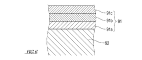
- FIG. 6 is a sectional view of the guide.
- the outer shell member 91 according to this embodiment includes a base layer portion 91a made of a metal plate material, an intermediate layer portion 91b formed on the outside of the base layer portion 91a and made of a heat insulating material, and an intermediate layer portion. It is formed on the outer side of 91b and has a layer structure with a surface layer portion 91c made of a refractory material.
- the surface layer portion 91c is provided with fire resistance. Further, in order to suppress the deformation of the guide 9 due to the heat of the main ash that has fallen, the intermediate layer portion 91b of the outer shell member 91 is provided with a heat insulating performance that blocks heat transmitted to the base layer portion 91a.
- the reinforcing member 92 gives the outer shell member 91 rigidity for shape retention.
- the reinforcing member 92 in the present embodiment is a space formed by the outer shell member 91 made of a material (filler) having both heat resistance and impact resistance such as mortar, concrete, and a cured resin material having heat resistance. It was poured and cured. In this way, the space formed by the outer shell member 91 of the guide 9 is filled with a heat-resistant / impact-resistant filler (reinforcing member 92). It is solid. Thereby, the guide 9 is provided with the impact strength which does not deform
- the reinforcing member 92 is not limited to the above filler.
- the reinforcing member 92 may be a frame, a block, or the like arranged in a space formed by the outer shell member 91.
- the guide 9 is attached to and supported by a beam 57 as a strength member spanned in the first direction X on the upper part of the frame 7.
- the joint between the beam 57 and the frame 7 is reinforced by using an L-shaped stay 58 and an I-shaped stay 59 so that the load resistance of the beam 57 is improved. Thereby, even if an impact load is applied to the guide 9, the guide 9 and the beam 57 are supported by the frame 7 without being bent or deformed.
- the guide 9 extends in the first direction X along the plurality of grizzly rivers 6 and has a length in the first direction X substantially equal to the distance between the pair of support walls 51 of the frame 7. Further, the guide 9 has a width in the second direction Y from the gap G to the axis of the grizzly river 6 forming the gap G. In this way, the upper part from the gap G to the axis of the grizzly river 6 forming the gap G is covered with the guide 9.
- the guide 9 that closes the gap G between the pair of grizzly rivers 6 and the frame 7 extends from the inside of the frame 7 to almost directly above the axial center of the pair of grizzly rivers 6 that is close to the frame 7.
- the guide 9 that closes the gap G between the two pairs of grizzly rivers 6 is a first guide from substantially right above the axis of one grizzly river 6 forming the gap G to almost right above the axis of the other grizzly river 6. It has a width in two directions Y.
- the guide 9 prevents the object to be sieved T from entering the gap G where the article to be sieved T may be engaged, and the article T that has fallen toward the gap G is guided to the slit S.
- the guide 9 is disposed above the grizzly river 6 so as to partially overlap with the grizzly river 6 in plan view. Therefore, the large block that has fallen mixed with the object to be sieved T collides with the guide 9 having impact resistance strength before the grizzly river 6. In this way, the grizzly river 6 is protected by the guide 9 so that the falling mass does not collide.
- the beam 57 supporting the guide 9 has a shape that substantially overlaps with the guide 9 in the vertical direction.
- the beam 57 also has a width in the second direction Y from the gap G to the axis of the grizzly river 6 forming the gap G.
- a narrow portion G ⁇ b> 1 of the gap between the beam 57 and the grizzly river 6 is formed above the axis of the grizzly river 6.
- the narrow portion G1 is set to have a vertical dimension so that only a sufficiently fine sieve T can pass through the gap G without clogging. The narrow portion G1 prevents the object T to be sieved around the grizzly river 6 from entering the gap G.
- the guide 9 has at least one guide surface 9g for guiding the object T to be sieved falling on the guide 9 to the slit S.
- the guide surface 9g is inclined with respect to the second direction Y so as to be lowered toward the slit S in the second direction Y.
- the central angle formed by the guide surface 9g of the guide 9 and the second direction Y is an acute angle of less than 90 °.
- the to-be-sieved object T that has fallen on the guide 9 is guided to the slit S located in the second direction Y as seen from the guide 9 without rolling by rolling according to gravity along the inclination of the guide surface 9g.
- the guide 9 has at least one inclined surface 9s for accelerating the movement of the sieve T that has fallen onto the guide 9 to the downstream side X2 in the first direction X.
- the inclined surface 9s is inclined with respect to the first direction X so as to descend as it proceeds to the downstream side X2 in the first direction X.
- the to-be-sieved object T that has fallen on the guide 9 rolls down according to gravity along the inclination of the inclined surface 9s, thereby promoting the movement in the first direction X toward the downstream side X2. Due to the action of the inclined surface 9s, the object to be sieved T and its fine particles are also dispersed to the downstream side X2 in the first direction X without staying on the surface of the guide 9.
- the guide 9 having the inclined surface 9s as described above is inclined with respect to the first direction X so that a part or all of the ridge line thereof is lowered as it proceeds to the downstream side X2 in the first direction X.
- the “ridge line” of the guide 9 is a line segment that connects the highest point from the bottom of the outer shape of the guide 9 in the first direction X when the guide 9 is viewed from the second direction Y.
- the bottom surface of the guide 9 is a plane parallel to the first direction X.
- the ridgeline of the guide 9 inclines from the horizontal more greatly than the inclination of the axis of the grizzly bar 6 from the horizontal in the grizzly device 5 in use.
- the inclination of the ridgeline of the guide 9 is steeper than the inclination of the axis of the grizzly river 6.
- the device 5 can be given. In other words, it is possible to provide the necessary inclination to the grizzly device 5 by the guide 9 while suppressing the inclination of the grizzly river 6 from the horizontal or regardless of the inclination of the grizzly river 6 from the horizontal.
- the guide 9 has a pyramid shape with the end on the upstream side X1 in the first direction X as a vertex.
- the guide 9 provided above the gap G between the grizzly rivers 6 adjacent in the second direction Y has an end surface and a bottom surface on the upstream side X1 in the first direction X.
- the guide 9 is directed toward the slit S so as to move down in the second direction Y, and is lowered as the guide surface 9g is inclined with respect to the second direction Y and the downstream side X2 in the first direction X. And one inclined surface 9s inclined with respect to the first direction X.
- the guide 9 provided above the gap G formed between the frame 7 adjacent to the second direction Y and the grizzly river 6 is formed in the shape of the quadrangular pyramid.
- the guide 9 is shaped in such a manner that it is cut in the center of the second direction Y in parallel with the first direction X.
- These guides 9 have one guide surface 9g and one inclined surface 9s.
- the guide 9 is mixed with the object to be sieved T, the function of blocking the upper part of the gap G and preventing the entry of the sieve T into the gap G, the function of guiding the article T to the slit S without delay. It has a function of protecting the grizzly river 6 from a large lump that has fallen.
- the shape of the guide 9 is not limited to this embodiment as long as it has the above function.
- the shape of the guide 9 may be selected from those shown in the table showing the variations of the guide 9 in FIG.
- FIG. 8 shows the shape of the guide 9 provided above the gap G between the grizzly bars 6 adjacent to each other in the second direction Y. The shape is parallel to the first direction X at the center of the second direction Y. If it cut
- the end face on the upstream side X1 in the first direction X is a triangle, and the end face on the upstream side X1 in the first direction X and the bottom face are orthogonal to each other.
- the A row and 1 column guide has a constant cross-sectional shape in the first direction X and has two guide surfaces 9g.
- the corner portion including the half ridge line on the downstream side X2 in the first direction X and the end surface on the downstream side X2 in the first direction X is cut off from the guide shown in the A row and 1 column. And has one inclined surface 9s in addition to the two guide surfaces 9g.
- the A row and 3 column guide is a quadrangular pyramid formed by cutting off a corner portion including a ridge line extending over the entire area in the first direction X from the guide shown in the A row and 1 column and the end face on the downstream side X2 in the first direction X. It has a shape, and has one inclined surface 9s in addition to the two guide surfaces 9g.
- the end surface on the upstream side X1 in the first direction X is pentagonal (home base type), and the end surface and the bottom surface on the upstream side X1 in the first direction X And are orthogonal.
- the guide in B row and 1 column has a constant cross-sectional shape in the first direction X and has two guide surfaces 9g.
- the corner portion including the ridge line on the downstream side X2 in the first direction X and the end surface on the downstream side X2 in the first direction X is cut off from the guide shown in the B row and 1 column. And has one inclined surface 9s in addition to the two guide surfaces 9g.
- the B row and 3 column guide has a shape in which corners including a ridge line extending in the entire first direction X from the guide shown in the B row and 1 column and the end surface of the downstream side X2 in the first direction X are cut off.
- the upper part is a quadrangular pyramid shape.
- the guide in B row and 3 column has one inclined surface 9s in addition to the two guide surfaces 9g.
- the guide shown in C row 1 to 3 column in FIG. 8 has a shape in which the ridge line portion is cut away from the guide in B row 1 to 3 column in parallel with the bottom surface.
- the guide of C row and 1 column has two guide surfaces 9g inclined with respect to the second direction Y.
- the guide in C row 2 to 3 column has one inclined surface 9s in addition to the two guide surfaces 9g.
- the guide shown in D row 1 to 3 column of FIG. 8 has a semicircular end surface on the upstream side X1 in the first direction X, and the end surface and the bottom surface on the upstream side X1 in the first direction X are perpendicular to each other. ing.
- the guide in D row and 1 column has a constant cross-sectional shape in the first direction X and has two guide surfaces 9g. In the guide shown in line D, the guide surface 9g is a curved surface.
- the guide shown in D row does not have a clear ridgeline, one and the other of the 2nd direction Y are each demonstrated as one guide surface 9g via the top part.
- the corner portion including the top half of the downstream side X2 in the first direction X and the end face of the downstream side X2 in the first direction X is scraped from the guide shown in the D row and first column. And has one inclined surface 9s in addition to the two guide surfaces 9g.
- the D row and 3 column guide has a shape in which corners including the top portion extending in the entire first direction X from the guide shown in the D row and 1 column and the end surface of the downstream side X2 in the first direction X are cut off. In addition to the two guide surfaces 9g, it has one inclined surface 9s.
- FIG. 9 is a diagram showing a schematic configuration of the main ash discharge system 1 according to one embodiment of the present invention.
- the main ash discharge system 1 includes a hopper 2, a separation device 3, and a conveyor device 4 from the upstream side toward the downstream side along the flow of the main ash movement.
- the hopper 2 receives the main ash falling from the boiler furnace 10 and discharges it to the downstream side (that is, the separation device 3).
- the hopper 2 is disposed below the boiler furnace 10 and is connected to the bottom of the boiler furnace 10.
- the hopper 2 has one or a plurality of cone portions 24 corresponding to the length of the boiler furnace 10 in the longitudinal direction.
- a closing valve device 21 is provided at or below the outlet 20 of each cone portion 24. The charging valve device 21 switches the charging and stopping of the main ash to the separation device 3 and adjusts the amount of main ash charged to the separation device 3.
- the separation device 3 receives the main ash discharged from the hopper 2, separates and collects a large mass of ash exceeding a predetermined size from the main flow of the main ash, and removes the remaining main ash on the downstream side (that is, It is discharged to the conveyor device 4).
- the inlet 30 of the box 31 that forms the flow path of the main ash in the separator 3 is connected to the outlet 20 of the cone portion 24 of the hopper 2.
- the box body 31 has a hopper shape (funnel shape) whose cross-sectional area decreases as it goes downward, and a fire-resistant material 313 having impact resistance is attached inside.
- the box body 31 is provided with an inlet 30 through which main ash flows in at the top, and an outlet 36 through which main ash flows out toward the conveyor device 4 and a discharge port 35 through which large lumps are discharged.
- the box body 31 has a first bottom portion 71 inclined from the horizontal and a second bottom portion 72 inclined from the horizontal in a direction opposite to the first bottom portion 71.
- the first bottom portion 71 and the second bottom portion 72 intersect at the bottom portion of the box body 31, whereby the bottom portion of the box body 31 is tapered.
- An outlet 36 of the box 31 is opened at the first bottom 71 of the box 31.
- a discharge port 35 of the box body 31 is opened at the second bottom portion 72 of the box body 31.
- each of the perpendicular line of the opening surface of the outlet 36 and the perpendicular line of the opening surface of the discharge port 35 has an inclination from the vertical direction, and the inclinations of these perpendicular lines have opposite horizontal components.
- the “opening surface” means a virtual plane defined by the edge of the opening.
- the inlet of the chute 32 is connected to the outlet 36 of the box 31 via the grizzly device 5. More specifically, the flange 75 (see FIG. 2) of the frame 7 of the grizzly device 5 is fastened to the opening edge of the outlet 36 of the box 31 with bolts, and the flange 76 (see FIG. 2) of the frame 7 is fastened. The opening edge of the entrance of the chute 32 is fastened with a bolt.
- the outlet of the chute 32 is connected to the casing 41 of the conveyor device 4.
- the frame 7 and the chute 32 of the grizzly device 5 connected to the box body 31 form a passage for sending the main ash flowing out from the outlet 36 of the box body 31 to the conveyor device 4.
- the grizzly device 5 is attached to the box 31 so that the grizzly river 6 is inclined 35 to 55 ° from the horizontal.
- the guide 9 of the grizzly device 5 enters the inside of the box 31 and forms a part of the first bottom portion 71.
- the ridgeline of the guide 9 is larger than the inclination of the grizzly river 6 from the horizontal, and is inclined 45 to 65 ° from the horizontal.
- the grizzly river 6 can be repaired and replaced individually by attaching and detaching the grizzly river 6 separately from the frame 7 while the frame 7 is coupled to the box 31 and the chute 32. At this time, the grizzly bar 6 and the shaft seal device 53 are moved in the first direction X with respect to the frame 7. As described above, by suppressing the inclination of the grizzly river 6 from the horizontal, the lifting height of the grizzly river 6 during maintenance work can be suppressed.
- an inspection port 39 is provided on a wall facing the outlet 36.
- An inspection port 321 is also provided on the wall of the chute 32 facing the grizzly device 5. These inspection ports 39 and 321 can be opened, and when clogging occurs in the grizzly device 5, the main ash clogged in the grizzly device 5 is crushed through at least one of the inspection ports 39 and 321. can do.
- the discharge port 35 of the box 31 is located on the extended line of the guide 9 of the grizzly device 5, and the lowest position of the discharge port 35 is the lowest position of the guide 9 of the grizzly device 5 (the first guide 9 of the guide 9 shown in FIG. 1).
- the lower end position of the guide 9 is smoothly continuous with the second bottom portion 72 of the box 31. In this way, the large mass of ash that has rolled down on the guide 9 can be moved to the discharge port 35 without any delay.
- the discharge port 35 of the box 31 is provided with a discharge valve device 38 that opens and closes the discharge port 35.
- the discharge valve device 38 according to the present embodiment includes a flap 381 that can close the discharge port 35, a drive mechanism 382 thereof, and a control device 383.
- the drive mechanism 382 is, for example, a hydraulic cylinder.
- the discharge port 35 is provided with an enclosure 162 surrounding the discharge port 35.
- the discharge port 35 When the discharge port 35 is opened, the inside of the enclosure 162 and the inside of the box 31 of the separation device 3 are communicated.
- a container 161 Inside the enclosure 162, below the discharge port 35, there is provided a container 161 for storing a large mass of ash that has fallen through the discharge port 35.
- the main ash dropped from the furnace bottom of the boiler furnace 10 to the hopper 2 passes through the hopper 2 and is put into the box 31 of the separation device 3.
- the main ash thrown into the box 31 falls on the upper surface of the grizzly device 5 according to gravity.
- the grizzly device 5 As described above, in the main ash discharge system 1, the ash mass is separated from the main ash mainstream in the separation device 3, and the separated ash mass is recovered.
- an extremely large lump of ash may fall on the grizzly device 5 included in the separation device 3, but the guide 9 prevents the large lump of ash from directly hitting the grizzly river 6.
- the solid guide 9 has an impact strength that can withstand a large lump hit, and even if a large lump of ash hits directly, deformation or damage that impairs its function does not occur.
- the grizzly device 5 can withstand the impact of the large ash mass that has fallen from the boiler furnace 10, and can separate the large ash mass from the main ash flow. Therefore, the grizzly device 5 is suitable as a separating means for separating a large mass of ash from the main ash flow in the main ash discharge system 1.
Landscapes
- Engineering & Computer Science (AREA)
- Mechanical Engineering (AREA)
- General Engineering & Computer Science (AREA)
- Combined Means For Separation Of Solids (AREA)
Priority Applications (4)
| Application Number | Priority Date | Filing Date | Title |
|---|---|---|---|
| CN201680072082.8A CN108367318B (zh) | 2015-12-25 | 2016-12-02 | 格筛装置和主灰排出系统 |
| EP16877956.9A EP3398694B1 (en) | 2015-12-25 | 2016-12-02 | Grizzly apparatus and bottom ash discharge system |
| US16/065,828 US10562072B2 (en) | 2015-12-25 | 2016-12-02 | Grizzly apparatus and bottom ash discharge system |
| KR1020187021011A KR102174951B1 (ko) | 2015-12-25 | 2016-12-02 | 그리즐리 장치 및 주재 배출 시스템 |
Applications Claiming Priority (2)
| Application Number | Priority Date | Filing Date | Title |
|---|---|---|---|
| JP2015-253123 | 2015-12-25 | ||
| JP2015253123A JP6722447B2 (ja) | 2015-12-25 | 2015-12-25 | グリズリ装置及び主灰排出システム |
Publications (1)
| Publication Number | Publication Date |
|---|---|
| WO2017110051A1 true WO2017110051A1 (ja) | 2017-06-29 |
Family
ID=59089878
Family Applications (1)
| Application Number | Title | Priority Date | Filing Date |
|---|---|---|---|
| PCT/JP2016/005049 Ceased WO2017110051A1 (ja) | 2015-12-25 | 2016-12-02 | グリズリ装置及び主灰排出システム |
Country Status (7)
| Country | Link |
|---|---|
| US (1) | US10562072B2 (https=) |
| EP (1) | EP3398694B1 (https=) |
| JP (1) | JP6722447B2 (https=) |
| KR (1) | KR102174951B1 (https=) |
| CN (1) | CN108367318B (https=) |
| TW (1) | TWI624423B (https=) |
| WO (1) | WO2017110051A1 (https=) |
Families Citing this family (4)
| Publication number | Priority date | Publication date | Assignee | Title |
|---|---|---|---|---|
| CN110404779A (zh) * | 2018-04-26 | 2019-11-05 | 苏州任我行自动化有限公司 | X型支架筛选轨道 |
| CN111974670B (zh) * | 2020-08-07 | 2022-02-08 | 云南曲靖钢铁集团凤凰钢铁有限公司 | 一种废弃钢渣回收处理设备 |
| CN116367933B (zh) * | 2020-11-02 | 2026-01-06 | 意昂能源基础设施公司 | 用于筛分颗粒流的装置和方法 |
| CN112871637B (zh) * | 2021-01-12 | 2022-08-02 | 湖南省煤业集团白山坪矿业有限公司 | 一种栅条间隙可调节的煤矿用振动给料设备 |
Citations (8)
| Publication number | Priority date | Publication date | Assignee | Title |
|---|---|---|---|---|
| US3848744A (en) * | 1972-12-04 | 1974-11-19 | J Flaherty | Green pellet sizing screen |
| JPS5576048U (https=) * | 1978-11-17 | 1980-05-26 | ||
| US4600106A (en) * | 1983-11-17 | 1986-07-15 | Maurice Minardi | Separation of molded parts from connectors |
| GB2239157A (en) * | 1989-12-19 | 1991-06-26 | Reekie Mfg Ltd | Roller separating tables for root crop harvesters |
| JPH0491773U (https=) * | 1990-12-25 | 1992-08-10 | ||
| US5175906A (en) * | 1990-06-01 | 1993-01-05 | Agricon, Inc. | Bean cleaning apparatus |
| JPH05139522A (ja) * | 1991-11-14 | 1993-06-08 | Mitsunori Saka | 回転式グリズリバー |
| JP2005233563A (ja) * | 2004-02-23 | 2005-09-02 | Jfe Engineering Kk | 廃棄物処理設備 |
Family Cites Families (19)
| Publication number | Priority date | Publication date | Assignee | Title |
|---|---|---|---|---|
| US2743813A (en) * | 1951-04-25 | 1956-05-01 | Lester E Erickson | Materials separating means |
| US3113574A (en) * | 1959-08-14 | 1963-12-10 | Fmc Corp | Corn conveying, orienting and husking machine |
| US3283895A (en) * | 1964-05-18 | 1966-11-08 | Hesston Mfg Co Inc | Beet cleaning apparatus |
| US3261108A (en) | 1964-12-02 | 1966-07-19 | Allis Chalmers Mfg Co | Grizzly bar construction |
| US3250277A (en) * | 1965-03-30 | 1966-05-10 | Morgan Packing Company Inc | Automatic controlled supply means for a corn husking machine |
| DE2140371A1 (de) * | 1971-08-12 | 1973-02-15 | Komen & Kuin N V Maschf | Sortiervorrichtung |
| US3900036A (en) * | 1974-10-03 | 1975-08-19 | Ronald L Anderson | Corn husking machine |
| DE3124446A1 (de) * | 1981-06-22 | 1982-12-30 | Felix 6712 Bobenheim-Roxheim Voll | Verfahren und vorrichtung zum sortieren und kalibrieren saemtlicher zwiebelgewaechse, von kartoffeln, moehren, roten beeten, gurken, rosenkohl, blumenkohl (gefrostet), radieschen und allen ballig geformten handelsguetern |
| US4396503A (en) * | 1981-08-10 | 1983-08-02 | Hein Lehmann Ag | Method and device for coating elements and screen elements made thereby |
| FR2545385B3 (fr) * | 1983-05-05 | 1986-07-25 | Raggi Jacques | Grille pour crible de premiere separation de calibrage pour produits heterogenes contenant des elements filiformes |
| US4804147A (en) * | 1987-12-28 | 1989-02-14 | Waste Management Energy Systems, Inc. | Process for manufacturing aggregate from ash residue |
| TW239183B (https=) * | 1993-06-01 | 1995-01-21 | Hitachi Shipbuilding Eng Co | |
| US5373947A (en) * | 1993-08-24 | 1994-12-20 | Kyowa Kogyo Co., Ltd. | Separator for removing foreign materials in granulated materials |
| JPH0714893U (ja) * | 1993-08-24 | 1995-03-14 | 協和工業株式会社 | 粒状物中の異物除去装置 |
| KR200312568Y1 (ko) * | 2003-01-17 | 2003-05-13 | 안두혁 | 골재 선별용 스크린 철망 |
| RU2351409C2 (ru) * | 2003-12-22 | 2009-04-10 | Ньютек Инджиниринг А/С | Устройство для контроля картофеля или подобных продуктов |
| CN102189076A (zh) * | 2010-03-04 | 2011-09-21 | 辛华 | 生物质滚轴筛 |
| JP2013230435A (ja) * | 2012-04-27 | 2013-11-14 | Hosokawa Micron Corp | 分級機 |
| JP6202394B2 (ja) * | 2014-02-14 | 2017-09-27 | 国立研究開発法人産業技術総合研究所 | 選別装置 |
-
2015
- 2015-12-25 JP JP2015253123A patent/JP6722447B2/ja active Active
-
2016
- 2016-12-02 KR KR1020187021011A patent/KR102174951B1/ko active Active
- 2016-12-02 US US16/065,828 patent/US10562072B2/en active Active
- 2016-12-02 CN CN201680072082.8A patent/CN108367318B/zh active Active
- 2016-12-02 EP EP16877956.9A patent/EP3398694B1/en active Active
- 2016-12-02 WO PCT/JP2016/005049 patent/WO2017110051A1/ja not_active Ceased
- 2016-12-08 TW TW105140625A patent/TWI624423B/zh active
Patent Citations (8)
| Publication number | Priority date | Publication date | Assignee | Title |
|---|---|---|---|---|
| US3848744A (en) * | 1972-12-04 | 1974-11-19 | J Flaherty | Green pellet sizing screen |
| JPS5576048U (https=) * | 1978-11-17 | 1980-05-26 | ||
| US4600106A (en) * | 1983-11-17 | 1986-07-15 | Maurice Minardi | Separation of molded parts from connectors |
| GB2239157A (en) * | 1989-12-19 | 1991-06-26 | Reekie Mfg Ltd | Roller separating tables for root crop harvesters |
| US5175906A (en) * | 1990-06-01 | 1993-01-05 | Agricon, Inc. | Bean cleaning apparatus |
| JPH0491773U (https=) * | 1990-12-25 | 1992-08-10 | ||
| JPH05139522A (ja) * | 1991-11-14 | 1993-06-08 | Mitsunori Saka | 回転式グリズリバー |
| JP2005233563A (ja) * | 2004-02-23 | 2005-09-02 | Jfe Engineering Kk | 廃棄物処理設備 |
Non-Patent Citations (1)
| Title |
|---|
| See also references of EP3398694A4 * |
Also Published As
| Publication number | Publication date |
|---|---|
| CN108367318A (zh) | 2018-08-03 |
| TWI624423B (zh) | 2018-05-21 |
| TW201726528A (zh) | 2017-08-01 |
| KR102174951B1 (ko) | 2020-11-05 |
| US10562072B2 (en) | 2020-02-18 |
| KR20180095076A (ko) | 2018-08-24 |
| JP2017113717A (ja) | 2017-06-29 |
| US20190009303A1 (en) | 2019-01-10 |
| EP3398694A1 (en) | 2018-11-07 |
| JP6722447B2 (ja) | 2020-07-15 |
| EP3398694A4 (en) | 2019-10-16 |
| EP3398694B1 (en) | 2023-02-01 |
| CN108367318B (zh) | 2021-08-13 |
Similar Documents
| Publication | Publication Date | Title |
|---|---|---|
| WO2017110051A1 (ja) | グリズリ装置及び主灰排出システム | |
| EP0056851B1 (en) | Thermal reactor of fluidizing bed type | |
| EP3388745B1 (en) | Ash discharge system | |
| CN103115365A (zh) | 循环流化床垃圾焚烧炉给料装置及给料方法 | |
| ITRM20090488A1 (it) | Sistema di estrazione e trasporto di ceneri leggere mediante trasportatore a nastro in acciaio. | |
| CN204769479U (zh) | 筛轴式筛分机 | |
| JP6850382B2 (ja) | グリズリ装置及び主灰排出システム | |
| JP6747396B2 (ja) | 粉体供給装置 | |
| JP6656747B2 (ja) | 搬送装置 | |
| Shah | Fundamentals, troubleshooting & maintenance of ash handling plants and pneumatic conveying systems for bulk materials | |
| CN116371517B (zh) | 一种井下采矿碎石安全输送装置及其输送方法 | |
| JP4133744B2 (ja) | ごみの受け入れ供給装置およびその運用方法 | |
| CN220469928U (zh) | 用于盾构机排渣的出渣装置 | |
| JPS61223421A (ja) | 流動層熱反応炉 | |
| JP2013103212A (ja) | 竪型粉砕装置およびそれを備えた石炭焚きボイラプラント | |
| CN109250432B (zh) | 自封闭落料斗 | |
| JP2005106435A (ja) | 不燃物分離ダンパ | |
| SU908877A1 (ru) | Устройство дл обработки сыпучих кусковых материалов | |
| US868102A (en) | Device for arresting the explosion discharge from blast-furnaces. | |
| US698449A (en) | Ash-remover for boiler-furnaces. | |
| ITMI952009A1 (it) | Sistema di filtrazione fumi a letto mobile di pietrisco | |
| JPS6260610B2 (https=) | ||
| Bresler | RETROFITTING MATERIALS HANDLING PLANT TO ALTER FLOW PATTERNS | |
| PL224056B1 (pl) | Urządzenie przenosząco-chłodzące |
Legal Events
| Date | Code | Title | Description |
|---|---|---|---|
| 121 | Ep: the epo has been informed by wipo that ep was designated in this application |
Ref document number: 16877956 Country of ref document: EP Kind code of ref document: A1 |
|
| NENP | Non-entry into the national phase |
Ref country code: DE |
|
| ENP | Entry into the national phase |
Ref document number: 20187021011 Country of ref document: KR Kind code of ref document: A |
|
| WWE | Wipo information: entry into national phase |
Ref document number: 1020187021011 Country of ref document: KR |
|
| WWE | Wipo information: entry into national phase |
Ref document number: 2016877956 Country of ref document: EP |
|
| ENP | Entry into the national phase |
Ref document number: 2016877956 Country of ref document: EP Effective date: 20180725 |