WO2017110043A1 - 鉄道車両用台車、その輪重調整方法、及び輪重調整システム - Google Patents
鉄道車両用台車、その輪重調整方法、及び輪重調整システム Download PDFInfo
- Publication number
- WO2017110043A1 WO2017110043A1 PCT/JP2016/005003 JP2016005003W WO2017110043A1 WO 2017110043 A1 WO2017110043 A1 WO 2017110043A1 JP 2016005003 W JP2016005003 W JP 2016005003W WO 2017110043 A1 WO2017110043 A1 WO 2017110043A1
- Authority
- WO
- WIPO (PCT)
- Prior art keywords
- vehicle
- liner
- axle box
- longitudinal direction
- leaf spring
- Prior art date
- Legal status (The legal status is an assumption and is not a legal conclusion. Google has not performed a legal analysis and makes no representation as to the accuracy of the status listed.)
- Ceased
Links
Images

Classifications
-
- B—PERFORMING OPERATIONS; TRANSPORTING
- B61—RAILWAYS
- B61F—RAIL VEHICLE SUSPENSIONS, e.g. UNDERFRAMES, BOGIES OR ARRANGEMENTS OF WHEEL AXLES; RAIL VEHICLES FOR USE ON TRACKS OF DIFFERENT WIDTH; PREVENTING DERAILING OF RAIL VEHICLES; WHEEL GUARDS, OBSTRUCTION REMOVERS OR THE LIKE FOR RAIL VEHICLES
- B61F5/00—Constructional details of bogies; Connections between bogies and vehicle underframes; Arrangements or devices for adjusting or allowing self-adjustment of wheel axles or bogies when rounding curves
- B61F5/26—Mounting or securing axle-boxes in vehicle or bogie underframes
- B61F5/30—Axle-boxes mounted for movement under spring control in vehicle or bogie underframes
- B61F5/301—Axle-boxes mounted for movement under spring control in vehicle or bogie underframes incorporating metal springs
- B61F5/302—Leaf springs
-
- B—PERFORMING OPERATIONS; TRANSPORTING
- B61—RAILWAYS
- B61F—RAIL VEHICLE SUSPENSIONS, e.g. UNDERFRAMES, BOGIES OR ARRANGEMENTS OF WHEEL AXLES; RAIL VEHICLES FOR USE ON TRACKS OF DIFFERENT WIDTH; PREVENTING DERAILING OF RAIL VEHICLES; WHEEL GUARDS, OBSTRUCTION REMOVERS OR THE LIKE FOR RAIL VEHICLES
- B61F3/00—Types of bogies
- B61F3/02—Types of bogies with more than one axle
- B61F3/08—Types of bogies with more than one axle without driven axles or wheels
-
- B—PERFORMING OPERATIONS; TRANSPORTING
- B61—RAILWAYS
- B61F—RAIL VEHICLE SUSPENSIONS, e.g. UNDERFRAMES, BOGIES OR ARRANGEMENTS OF WHEEL AXLES; RAIL VEHICLES FOR USE ON TRACKS OF DIFFERENT WIDTH; PREVENTING DERAILING OF RAIL VEHICLES; WHEEL GUARDS, OBSTRUCTION REMOVERS OR THE LIKE FOR RAIL VEHICLES
- B61F5/00—Constructional details of bogies; Connections between bogies and vehicle underframes; Arrangements or devices for adjusting or allowing self-adjustment of wheel axles or bogies when rounding curves
- B61F5/26—Mounting or securing axle-boxes in vehicle or bogie underframes
- B61F5/30—Axle-boxes mounted for movement under spring control in vehicle or bogie underframes
- B61F5/32—Guides, e.g. plates, for axle-boxes
-
- B—PERFORMING OPERATIONS; TRANSPORTING
- B61—RAILWAYS
- B61F—RAIL VEHICLE SUSPENSIONS, e.g. UNDERFRAMES, BOGIES OR ARRANGEMENTS OF WHEEL AXLES; RAIL VEHICLES FOR USE ON TRACKS OF DIFFERENT WIDTH; PREVENTING DERAILING OF RAIL VEHICLES; WHEEL GUARDS, OBSTRUCTION REMOVERS OR THE LIKE FOR RAIL VEHICLES
- B61F5/00—Constructional details of bogies; Connections between bogies and vehicle underframes; Arrangements or devices for adjusting or allowing self-adjustment of wheel axles or bogies when rounding curves
- B61F5/50—Other details
- B61F5/52—Bogie frames
Definitions
- the present invention relates to a railway vehicle bogie, its wheel load adjusting method, and a wheel load adjusting system.
- an axle box that houses a bearing that rotatably supports a wheel shaft is supported by a bogie frame via an axle box support device.
- the bogie frame has a pair of side beams extending in the longitudinal direction of the vehicle and a side beam connecting the pair of side beams in the vehicle width direction, and the axle box support device (axial spring) is a shaft.
- the box and the side frame of the bogie frame are connected.
- Patent Document 2 proposes a cart having a leaf spring which is long in the longitudinal direction of the vehicle, omitting the side beams in the cart frame.
- the center in the longitudinal direction of the leaf spring is supported by mounting portions provided at both ends of the lateral width in the vehicle width direction, and both longitudinal ends of the leaf spring are inserted into spring receivers formed in the axle box.
- wheel load adjustment work for adjusting the wheel load balance between the wheels is performed.
- the balance of wheel load is adjusted by changing the spring constant of the shaft spring by inserting a liner between the shaft box and the shaft spring, or by removing the inserted liner. Is done.
- an object of the present invention is to improve the workability of wheel load adjustment in a state where a railway vehicle is present.
- a railcar bogie includes a rail for supporting a vehicle body of a railcar, a shaft box that houses a bearing that rotatably supports a wheel shaft, and a support provided on an upper portion of the shaft box.
- a shaft beam facing the plate spring in the vertical direction, and an upper surface of the shaft beam has an installation surface on which a push-up device for pushing up the lower surface of the plate spring can be installed.
- An installation seat is provided.
- a wheel load adjustment method for a railway vehicle bogie includes a lateral beam for supporting a vehicle body of a railway vehicle, a shaft box that houses a bearing that rotatably supports a wheel shaft, A support member provided at an upper portion, a leaf spring extending in the longitudinal direction of the vehicle in a state of supporting both ends in the vehicle width direction of the side beam, and both ends in the longitudinal direction of the vehicle supported by the support member; and the axle box
- a wheel load adjustment method for a railway vehicle bogie comprising a shaft beam coupled to the longitudinal direction of the vehicle and a shaft beam facing the plate spring in the vertical direction, and provided on an upper surface of the shaft beam.
- a push-up device that pushes up the lower surface of the plate spring on the installation surface of the installation seat; and by pushing up the lower surface of the plate spring by operating the push-up device, between the support member and the axle box Generating a gap in the gap and a line in the gap.
- a wheel load adjustment system includes a railcar bogie and a lifting device, and the railcar bogie is capable of rotating a horizontal shaft and a wheel shaft for supporting a railcar body.
- An axle box that houses a bearing to be supported on the axle, a support member provided on the upper part of the axle box, and extending in the vehicle longitudinal direction while supporting both ends in the vehicle width direction of the lateral beam, both ends in the vehicle longitudinal direction
- the lower surface of the leaf spring is pushed up, and an installation seat having an installation surface on which the push-up device can be installed is provided on the upper surface of the shaft beam.
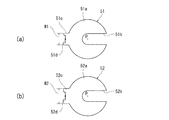
- FIG. 3 is a plan view of a first liner and a second liner shown in FIG. 2.
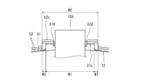
- FIG. 3 is a diagram showing a state where one first liner and two second liners are inserted into the axle box shown in FIG. 2.
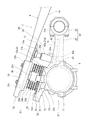
- FIG. 1 is a side view of a railway vehicle carriage 1 according to an embodiment.
- a railcar bogie (hereinafter referred to as a bogie) 1 includes a bogie frame 3 for supporting a vehicle body 30 via an air spring 2.
- the bogie frame 3 includes a horizontal beam 4 extending in the vehicle width direction at the vehicle longitudinal direction center of the bogie 1.
- the bogie frame 3 extends from the vehicle width direction both ends 4a of the horizontal beam 4 in the vehicle longitudinal direction. There is no extending side beam.
- An axle 6 extending along the vehicle width direction is disposed on both sides of the lateral beam 4 in the longitudinal direction of the vehicle.
- Wheels 7 are press-fitted on both sides of the axle 6 in the vehicle width direction.
- the axle 6 and the wheel 7 constitute a wheel shaft 15.
- the pair of wheel shafts 15 provided on the carriage 1 are disposed on both sides of the lateral beam 4 in the longitudinal direction of the vehicle.
- Bearings 8 that rotatably support the wheels 7 on the outer side in the vehicle width direction than the wheels 7 are provided at both ends of the axle 6 in the vehicle width direction.
- the bearings 8 are accommodated in the axle box 10.
- the axle box 10 is elastically connected to the side beam 4 of the carriage frame 3 via the axle box support device 16.
- the axle box support device 16 includes an axle beam 21 that couples the axle box 10 and the lateral beam 4 in the longitudinal direction of the vehicle.
- the shaft beam 21 is formed integrally with the shaft box 10 and extends from the shaft box 10 toward the side beam 4 in the longitudinal direction of the vehicle.
- a cylindrical portion 21b (see FIG. 2) that opens on both sides in the vehicle width direction is formed at the tip of the shaft beam 21, and the cylindrical portion 21b is provided at the vehicle width direction end portion 4a of the horizontal beam 4. It is elastically connected to the receiving seat 4b via a rubber bush and a mandrel (not shown).
- a leaf spring 9 extending in the longitudinal direction of the vehicle is bridged between the axle box 10 and the side wall 4.
- the leaf spring 9 supports the vehicle width direction end portion 4a of the lateral beam 4 from below at the vehicle longitudinal direction central portion 9a, and the vehicle longitudinal direction both end portions 9b of the leaf spring 9 are indirectly attached to the axle box 10. It is supported. That is, the leaf spring 9 has the function of a primary suspension and the function of a conventional side beam.
- Both end portions 9 b of the plate spring 9 in the longitudinal direction of the vehicle are supported by the axle box 10 via support members 31.
- the support member 31 is provided on the upper portion of the axle box 10.
- the support member 31 includes a receiving member 32 and a vibration isolating rubber unit 33.
- the receiving member 32 supports the vehicle longitudinal direction both ends 9b of the leaf spring 9 from below.
- the anti-vibration rubber unit 33 has a substantially cylindrical shape, and is inserted between the axle box 10 and the receiving member 32.
- the anti-vibration rubber unit 33 includes a plurality of rubber plates 33a and a plurality of metal plates 33b interposed between the plurality of rubber plates 33a (see FIG. 2).
- the upper surface of the vibration isolating rubber unit 33 is inclined obliquely downward toward the center in the vehicle longitudinal direction.
- the upper surface of the vibration isolating rubber unit 33 may not be inclined as long as it is substantially parallel to the lower surface of the vehicle longitudinal direction end portion 9b of the leaf spring 9.
- the axle box 10 has an axle box body 11 in which the bearing 8 is accommodated, and a spring seat 12 that indirectly supports the leaf spring 9.
- the spring seat 12 is formed integrally with the axle box main body 11. Further, a plurality of liners 51 and 52 described later (see FIG. 4) are provided between the spring seat 12 and the anti-vibration rubber unit 33, specifically, between the upper surface of the spring seat 12 and the lower surface of the anti-vibration rubber unit 33. A liner set 50 is interposed.
- the liner set 50 is a group of liner parts used to adjust the wheel load balance of each wheel 7 when the railway vehicle is present.
- the wheel load adjustment operation is performed by selectively interposing a liner set 50 between the leaf spring 9 and the axle box 10 for transmitting the load from the vehicle body 30 to the wheel 7.
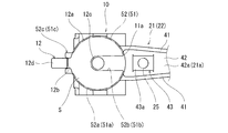
- FIG. 2 is a side view of the main part of the carriage 1 in a state where the hydraulic jack 25 is installed on the upper surface 21a of the shaft beam 21 shown in FIG.
- FIG. 3 is a plan view of the axle box 10 shown in FIG. 2 and its surroundings.
- the shaft beam 21 has a shaft beam main body portion 22 and a shaft beam end portion 23.
- the shaft beam main body portion 22 has a pair of side plate portions 41 extending from the axle box 10 in the vehicle longitudinal direction, and a connecting plate portion 42 for connecting the pair of side plate portions 41 in the vehicle width direction, as viewed from the vehicle longitudinal direction. It has an H-shaped cross-sectional shape.
- the shaft beam main body 22 is provided with an installation seat 43 on which the hydraulic jack 25 can be installed.
- the installation seat 43 is provided on the upper surface 42 a of the coupling plate portion 42 in a state covered with the pair of side plate portions 41 from both sides in the vehicle width direction.
- the installation seat 43 may be formed integrally with the shaft beam 21 or may be fixed by welding or the like.
- the installation seat 43 has an installation surface 43a on which the hydraulic jack 25 can be installed, and is substantially parallel to the lower surface 9c of the leaf spring 9.
- the angle at which the installation surface 43a is inclined is different from the angle at which the upper surface 42a of the connecting plate portion 42 is inclined.
- the hydraulic jack 25 is attached in a substantially vertical direction with respect to the lower surface 9c of the leaf spring 9.
- the hydraulic jack 25 is also inclined with respect to the horizontal plane.
- the wheel load adjustment system 60 is roughly composed of a carriage 1 and a hydraulic jack 25.
- the hydraulic jack 25 includes a substantially cylindrical cylinder 25a in which an oil chamber to which hydraulic oil is supplied is formed, and a piston 25b partially protruding from the upper surface of the cylinder 25a, and the piston 25b expands and contracts in the axial direction. To do.
- the worker When performing the wheel load adjustment work, the worker installs the hydraulic jack 25 on the installation seat 43 provided on the connecting plate portion 42.
- the installation seat 43 is covered by the pair of side plate portions 41 of the shaft beam 21 from both sides in the vehicle width direction.
- the hydraulic jack 25 When the hydraulic jack 25 is installed on the installation seat 43, the hydraulic jack 25 is connected to the pair of side plates of the shaft beam 21.
- the portion 41, the connecting plate portion 42, the leaf spring 9, and the axle box body 11 are disposed. Therefore, when the hydraulic jack 25 is operated, it does not fall off from the installation location.
- a steel pad 17 having a rubber plate attached to the contact surface side with the plate spring 9 is attached.
- the pad 17 includes a groove portion 17a into which the upper end portion of the piston 25b is fitted and a contact surface 17b.
- the pad 17 is attached when the hydraulic jack 25 is installed during the wheel load adjustment work.
- the contact surface 17b is subjected to spherical processing.
- a member may be interposed.
- a liner set 50 is interposed in advance between the spring seat 12 of the axle box 10 and the vibration isolating rubber unit 33.
- the liner set 50 may be interposed between the anti-vibration rubber unit 33 and the receiving member 32.
- the liner set 50 illustrated in the present embodiment includes a plurality of liners including one first liner 51 and two second liners 52 having different thicknesses. The number of liners and the type of thickness are appropriately selected in order to obtain an appropriate wheel load value. The shape of the liner will be described later.
- the spring seat 12 has a substantially circular installation portion 12a in plan view where the liners 51 and 52 are installed.
- the upper surface S of the installation portion 12a is substantially parallel to the lower surface 9c of the leaf spring 9, and is inclined obliquely downward toward the center side in the vehicle longitudinal direction.
- the spring seat 12 is formed with a first protrusion 12c that protrudes upward from the center of the installation part 12a and a second protrusion 12d that protrudes upward from the end in the vehicle longitudinal direction.
- the first projecting portion 12 c has a substantially cylindrical shape and is inserted into a lower through hole 33 c formed on the lower surface of the vibration isolating rubber unit 33.
- the second protruding portion 12d is adjacent to the protruding portion 12b of the installation portion 12a and protrudes upward from the protruding portion 12b.
- a first liner 51 and a second liner 52 engage with the first protrusion 12c and the second protrusion 12d.
- the receiving member 32 has a substantially rectangular shape in plan view, and supports both end portions 9b of the leaf spring 9 in the vehicle longitudinal direction.
- the receiving member 32 has a bottom wall portion 32a, an outer wall portion 32b, and a protruding portion 32c that protrudes downward from the lower surface of the bottom wall portion 32a.
- the protruding portion 32 c is inserted into the upper through hole 33 d of the vibration isolating rubber unit 33.
- FIG. 4A is a plan view of the first liner 51 shown in FIG.
- FIG. 4B is a plan view of the second liner 52 shown in FIG.
- the first liner 51 and the second liner 52 have pressure receiving portions 51a and 52a, first engaging portions 51b and 52b, and second engaging portions 51c, respectively. 52c.
- the pressure receiving portions 51a and 52a are portions that receive a load from the leaf spring 9, and the outer edges thereof are substantially C-shaped with a part of a circle cut out in plan view.
- the first engaging portions 51b and 52b are formed by indenting part of the outer edges of the pressure receiving portions 51a and 52a inward. Specifically, the first engaging portions 51b and 52b are recessed toward the center P of a circle formed by the outer edges of the pressure receiving portions 51a and 52a.
- the second engaging portions 51c and 52c protrude outward from the pressure receiving portions 51a and 52a on the side opposite to the first engaging portions 51b and 52b, and have concave notches 51d and 52d at the tips.
- the notch widths of the notches 51d and 52d are set to be the same as or slightly larger than the dimension in the vehicle width direction of the second protrusion 12d.
- first liner 51 and the second liner 52 have different thicknesses, and the width direction dimension W1 of the first liner 51 is smaller than the width direction dimension W2 of the second engagement portion 52c.
- the operator uses a tool such as pliers to grip the second engaging portion of the liner, and then removes the liner from the longitudinal direction of the vehicle.
- the width of the second engaging portion depends on the thickness of the liner. Since the dimensions are different, it is easy to distinguish liners having different thicknesses, and attachment / detachment work becomes easy.
- the liners 51 and 52 are displaced inward in the vehicle longitudinal direction and the vehicle. Displacement in the width direction is restricted. Furthermore, the second engaging portions 51c and 52c engage with the second engaged portion 12d provided at the end of the spring seat 12 on the vehicle longitudinal direction outer side, so that the liners 51 and 52 move outward in the vehicle longitudinal direction. Displacement is regulated. Furthermore, when the concave notches 51d and 52d are fitted into the second engaged portion 12d, the rotational displacement about the first engaged portion 12c is also restricted.
- FIG. 5 is a view showing a state in which one first liner 51 and two second liners 52 are inserted into the axle box 10.
- the thin first liner 51 is inserted below the thick second liner 52, and is sandwiched between the spring seat 12 and the second liner 52.
- the width direction dimension W1 of the notch portion 51d of the first liner 51 is smaller than the width direction dimension W2 of the notch portion 52d of the second liner 52, and thus the second engagement portion 51c of the first liner 51.
- a second engaging portion 52c of the second liner 52 is formed with a stepped portion W3. Thereby, the operator can easily pull out the desired liner by gripping the second engagement portion.
- wheel load adjustment is performed by the following steps.
- a push-up device 25 (see FIG. 2), which is a hydraulic jack, for example, is installed on the shaft beam 21.
- the hydraulic jack 25 is operated to push up the lower surface 9 c of the leaf spring 9, thereby generating a gap between the receiving member 32 and the vibration isolating rubber unit 33.
- lifting the anti-vibration rubber unit 33 creates a gap between the spring seat 12 of the axle box 10 and the anti-vibration rubber unit 33, so that the liners 51 and 52 can be inserted, or The inserted liners 51 and 52 can be extracted.
- the cart 1 and the wheel load adjustment system 60 configured as described above have the following effects.
- an installation seat 43 capable of installing the hydraulic jack 25 is provided on the upper surface 21 a of the shaft beam 21 facing the leaf spring 9 in the vertical direction.
- the lower surface 9c of the leaf spring 9 can be pushed up by the hydraulic jack 25 during the wheel load adjustment work. Therefore, the liners 51 and 52 for adjusting the wheel load balance can be attached and detached by pushing up the lower surface 9c of the leaf spring 9 to generate a gap between the spring seat 12 and the vibration isolating rubber unit 33. . Therefore, when the wheel load adjustment work is performed in the state where the railway vehicle including the leaf spring type carriage 1 is present, it is not necessary to remove the plate spring 9 and the workability of the wheel load adjustment can be improved.
- the hydraulic jack 25 can be easily attached to the leaf spring 9 in a substantially vertical direction. Accordingly, the wheel load adjustment work is easier than the configuration in which the pressing force by the hydraulic jack 25 is easily applied in a substantially vertical direction to the lower surface 9c of the leaf spring 9, and the hydraulic jack is inclined and attached to the lower surface of the leaf spring. The pressing force required at times can be minimized.
- the installation seat 43 is provided on the upper surface 42a of the connecting plate portion 42 in a state where it is covered by the pair of side plate portions 41 of the shaft beam 21 from both the vehicle longitudinal direction and the vehicle width direction.
- the hydraulic jack 25 is disposed so as to be surrounded by the pair of side plate portions 41, the connecting plate portion 42, the plate spring 9, and the axle box main body 11. Therefore, it is possible to prevent the hydraulic jack 25 from falling off the shaft beam 21 outward.
- the angle at which the installation surface 43 a of the installation seat 43 is inclined is different from the angle at which the upper surface 42 a of the connecting plate portion 42 is inclined.
- the receiving member 32 is fixed to the vibration isolating rubber unit 33, and the cover member 34 is fixed to the receiving member 32 so as to cover both ends 9b of the leaf spring 9 in the vehicle longitudinal direction from above.
- the hydraulic jack 25 pushes up the lower surface 9 c of the plate spring 9
- the receiving member 32 is pushed up together with the plate spring 9.
- a gap can be generated between the vibration isolating rubber unit 33 and the receiving member 32.
- a gap for attaching and detaching the liner can also be provided between the spring seat 12 of the axle box 10 and the anti-vibration rubber unit 33.
- the first liner 51 and the second liner 52 having different thicknesses have second engaging portions 51c and 52c having different outer shapes.
- the first liner 51 and the second liner 52 are spring seats. 12 and the anti-vibration rubber unit 33, the second engaging portion 51c of the first liner 51 and the second engaging portion 52c of the second liner 52 form a step. Therefore, the operator can easily grasp the difference in thickness of the plurality of liners 51 and 52 stacked from the difference in level difference, and can easily grasp the second engaging portion of the desired liner as a grip margin. Can do. Thereby, workability
- the second engaging portion 51 c of the first liner 51 becomes the axle box 10. Therefore, it is possible to prevent the first liner 51 from falling off the axle box 10 while realizing a good engagement state. Further, since the outer shape of the second engaging portions 51c and 52c stacked on each other is larger in the upper layer, it is easy to grip the second engaging portion 52c in the upper layer, and the operation of extracting the liners 51 and 52 in order from the upper layer is performed. It can be done easily.
- the present invention is not limited to the above-described embodiment, and the configuration can be changed, added, or deleted without departing from the spirit of the present invention.
- the outer shapes of the second engagement portions 51c and 52c are made different by making the width direction dimensions W1 and W2 of the second engagement portions 51c and 52c of the liners 51 and 52 different from each other. If it is a shape which can recognize the difference in the thickness of the liners 51 and 52 when engaging with the 2nd to-be-engaged part 12d provided in the spring seat 12 of the axle box 10, it will not be restricted to this structure.
- the second engaging portions 51c and 52c may be color-coded by painting.
- the second engaged portion 12d provided on the spring seat 12 of the axle box 10 protrudes outward from the vehicle longitudinal direction outer end portion of the installation portion 12a.
- the second engaged portion 12d may protrude outward from the outer end of the installation portion 12a in the vehicle width direction. That is, the liners 51 and 52 may be inserted between the spring seat 12 and the vibration isolating rubber unit 33 from the outside in the vehicle width direction.
- the push-up device 25 is not limited to a hydraulic jack, and may be an air jack or the like. In the embodiment, two types of liners having different thicknesses are used.
Landscapes
- Engineering & Computer Science (AREA)
- Mechanical Engineering (AREA)
- Vibration Prevention Devices (AREA)
- Springs (AREA)
- Vehicle Body Suspensions (AREA)
Abstract
鉄道車両用台車は、横ばりと、軸箱と、支持部材と、板バネと、軸ばりとを備える。軸箱は、輪軸を回転自在に支持する軸受を収容する。支持部材は、軸箱の上部に設けられる。板バネは、横ばりの車幅方向両端部を支持した状態で車両長手方向に延びて、その車両長手方向両端部が支持部材に支持される。軸ばりは、軸箱と横ばりとを車両長手方向に連結し、板バネと上下方向に対向している。軸ばりの上面には、板バネの下面を押し上げる押上装置を設置可能な設置面を有する設置座が設けられている。
Description
本発明は、鉄道車両用台車、その輪重調整方法、及び輪重調整システムに関する。
鉄道車両用台車では、輪軸を回転自在に支持する軸受を収容する軸箱が軸箱支持装置を介して台車枠に支持されている。例えば、特許文献1では、台車枠が、車両長手方向に延びる一対の側ばりと、その一対の側ばりを車幅方向につなぐ横ばりとを有し、軸箱支持装置(軸バネ)が軸箱と台車枠の側ばりとを接続している。
また、特許文献2では、台車枠のうち側ばりを省略して、車両長手方向に長い板バネを有する台車が提案されている。板バネの長手方向中央は、横ばりの車幅方向両端部に設けられた取付部に支持されると共に、板バネの長手方向両端が軸箱に形成されたバネ受け内に挿入されている。
ところで、鉄道車両のメンテナンス時には、車輪間の輪重バランスを調整する輪重調整作業が行われる。例えば、特許文献1に示す台車では、軸箱と軸バネとの間にライナーを挿入したり、挿入されていたライナーを抜き出すことにより、軸バネのバネ定数を変化させて、輪重バランスが調整される。
特許文献1に示す台車においては、軸バネ座と軸箱との間に油圧ジャッキを2つ取り付けて輪重調整作業を行う必要があるため、作業性が悪かった。
また、特許文献2に示す台車では、輪重調整時には、板バネと軸箱との間に隙間を設け、当該隙間にライナーを挿入する等の作業を行うことが考えられるが、具体的にどのように輪重調整を行うのか述べられていない。
そこで本発明は、鉄道車両の在姿状態において、輪重調整の作業性を向上させることを目的としている。
本発明の一形態に係る鉄道車両用台車は、鉄道車両の車体を支持するための横ばりと、輪軸を回転自在に支持する軸受を収容する軸箱と、前記軸箱の上部に設けられる支持部材と、前記横ばりの車幅方向両端部を支持した状態で車両長手方向に延びて、その車両長手方向両端部が前記支持部材に支持される板バネと、前記軸箱と前記横ばりとを前記車両長手方向に連結し、前記板バネと上下方向に対向する軸ばりと、を備え、前記軸ばりの上面には、前記板バネの下面を押し上げる押上装置を設置可能な設置面を有する設置座が設けられている。
本発明の一形態に係る鉄道車両用台車の輪重調整方法は、鉄道車両の車体を支持するための横ばりと、輪軸を回転自在に支持する軸受を収容する軸箱と、前記軸箱の上部に設けられる支持部材と、前記横ばりの車幅方向両端部を支持した状態で車両長手方向に延びて、その車両長手方向両端部が前記支持部材に支持される板バネと、前記軸箱と前記横ばりとを前記車両長手方向に連結し、前記板バネと上下方向に対向する軸ばりと、を備える鉄道車両用台車の輪重調整方法であって、前記軸ばりの上面に設けられた設置座の設置面に前記板バネの下面を押し上げる押上装置を設置する工程と、前記押上装置を作動させることで前記板バネの前記下面を押し上げて、前記支持部材と前記軸箱との間に隙間を発生させる工程と、前記隙間にライナーを挿入する又は前記支持部材と前記軸箱との間に予め挿入されているライナーを抜き出す工程と、を備える。
本発明の一形態に係る輪重調整システムは、鉄道車両用台車と、押上装置と、を備え、前記鉄道車両用台車は、鉄道車両の車体を支持するための横ばりと、輪軸を回転自在に支持する軸受を収容する軸箱と、前記軸箱の上部に設けられる支持部材と、前記横ばりの車幅方向両端部を支持した状態で車両長手方向に延びて、その車両長手方向両端部が前記支持部材に支持される板バネと、前記軸箱と前記横ばりとを前記車両長手方向に連結し、前記板バネと上下方向に対向する軸ばりと、を有し、前記押上装置は、前記板バネの下面を押し上げ、前記軸ばりの上面には、前記押上装置を設置可能な設置面を有する設置座が設けられている。
前記各構成によれば、軸箱と横ばりとを連結する軸ばりの上面に押上装置を設置可能な設置座を設けたことで、在姿状態で輪重バランスの調整作業を行う際に、板バネの下面を押上装置によって押し上げることが可能となる。よって、板バネの下面を押し上げて隙間を発生させることにより、当該隙間に輪重バランスを調整するためのライナーを挿入する又は予め挿入されているライナーを容易に抜き出すことができる。したがって、板バネ式の鉄道車両用台車を備えた鉄道車両の在姿状態において、輪重調整のために板バネを取り外す必要が無く、輪重調整の作業性を向上させることができる。
本発明によれば、鉄道車両の在姿状態において、輪重調整の作業性を向上させることができる。
以下、図面を参照しながら実施形態について説明する。なお、同一の又は対応する要素には全ての図を通じて同一の符号を付して重複する詳細説明を省略する。
図1は、実施形態に係る鉄道車両用台車1の側面図である。図1に示すように、鉄道車両用台車(以下、台車と呼ぶ)1は、空気バネ2を介して車体30を支持するための台車枠3を備えている。台車枠3は、台車1の車両長手方向中央において車幅方向に延びる横ばり4を備えるが、従来の台車枠の構成とは異なり、横ばり4の車幅方向両端部4aから車両長手方向に延びる側ばりを備えていない。
横ばり4の車両長手方向両側には、それぞれ車幅方向に沿って延びる車軸6が配置されている。車軸6の車幅方向両側には車輪7が圧入される。車軸6及び車輪7は、輪軸15を構成する。そして、台車1に設けられた一対の輪軸15は、横ばり4の車両長手方向両側に離間して配置されている。車軸6の車幅方向両側の端部には、車輪7よりも車幅方向外側にて車輪7を回転自在に支持する軸受8が設けられ、その軸受8は軸箱10に収容される。
軸箱10は、軸箱支持装置16を介して台車枠3の横ばり4に弾性的に連結されている。軸箱支持装置16は、軸箱10と横ばり4とを車両長手方向に連結する軸ばり21を備えている。軸ばり21は、軸箱10と一体に成形されて当該軸箱10から車両長手方向のうち横ばり4側に向かって延びている。軸ばり21の先端には、車幅方向両側に開口する筒状部21b(図2参照)が形成されており、当該筒状部21bが横ばり4の車幅方向端部4aに設けられた受け座4bに対して、ゴムブッシュ及び心棒(図示せず)を介して弾性的に連結されている。
軸箱10と横ばり4との間には、車両長手方向に延びる板バネ9が架け渡されている。板バネ9は、その車両長手方向中央部9aにおいて、横ばり4の車幅方向端部4aを下方から支持しており、板バネ9の車両長手方向両端部9bは、軸箱10に間接に支持されている。即ち、板バネ9は、一次サスペンションの機能と従来の側ばりの機能とを有している。
板バネ9の車両長手方向両端部9bは、支持部材31を介して軸箱10に支持されている。支持部材31は、軸箱10の上部に設けられている。そして、支持部材31は、受け部材32と、防振ゴムユニット33とを有している。受け部材32は、板バネ9の車両長手方向両端部9bを下方から支持している。防振ゴムユニット33は略円柱状であり、軸箱10と受け部材32との間に挿入されている。防振ゴムユニット33は、複数のゴム板33aと、当該複数のゴム板33aの間に介装された複数の金属板33bとによって構成されている(図2参照)。防振ゴムユニット33の上面は、車両長手方向の中央側に向けて斜め下方に傾斜している。なお、防振ゴムユニット33の上面は、板バネ9のうち車両長手方向端部9bの下面と略平行であれば、傾斜していなくてもよい。
軸箱10は、軸受8が収容された軸箱本体11と、板バネ9を間接に支持するバネ座12とを有している。本実施形態では、バネ座12は、軸箱本体11と一体に成形されている。また、バネ座12と防振ゴムユニット33との間、具体的には、バネ座12の上面と防振ゴムユニット33の下面との間には後述する複数のライナー51,52(図4参照)からなるライナーセット50が介在している。
ライナーセット50は、鉄道車両の在姿状態において、各車輪7の輪重バランスを調整するために用いるライナーの部品群である。車体30からの荷重を車輪7に伝える板バネ9と軸箱10との間にライナーセット50を選択的に介在させて輪重調整作業を行う。
図2は、図1に示す軸ばり21の上面21aに油圧ジャッキ25を設置した状態の台車1の要部側面図である。図3は、図2に示す軸箱10及びその周辺の平面図である。図2及び3に示すように、軸ばり21は、軸ばり本体部22と、軸ばり端部23とを有している。軸ばり本体部22は、軸箱10から車両長手方向に延びる一対の側板部41と、一対の側板部41を車幅方向に連結する連結板部42とを有し、車両長手方向から見てH形の断面形状を有している。
軸ばり本体部22には、油圧ジャッキ25を設置可能な設置座43が設けられている。具体的には、設置座43は、一対の側板部41により車幅方向両側から覆われた状態で連結板部42の上面42aに設けられている。設置座43は、軸ばり21と一体に成形されていていてもよいし、溶接等で固定されていてもよい。
設置座43は、油圧ジャッキ25を設置可能な設置面43aを有し、板バネ9の下面9cと略平行である。ここで、設置面43aが傾斜する角度は、連結板部42の上面42aが傾斜する角度と異なる。
油圧ジャッキ25は、板バネ9の下面9cに対して略垂直方向に取り付けられる。ここで、板バネ9の下面9cは水平面に対して傾斜しているため、油圧ジャッキ25も水平面に対して傾斜して設置される。
図2に示すように、輪重調整システム60は、概略、台車1と、油圧ジャッキ25とから構成される。油圧ジャッキ25は、作動油が供給される油室が形成された略円筒状のシリンダ25aと、シリンダ25aの上面から一部が突出するピストン25bとを有し、ピストン25bは軸線方向に伸縮動作する。
輪重調整作業を行う場合、作業者は、油圧ジャッキ25を連結板部42に設けられた設置座43に設置する。設置座43は軸ばり21の一対の側板部41に車幅方向両側から覆われていると共に、油圧ジャッキ25を設置座43に設置したとき、当該油圧ジャッキ25は、軸ばり21の一対の側板部41と連結板部42と板バネ9と軸箱本体11に囲まれて配置されている。そのため、油圧ジャッキ25を作動させた際に、設置箇所から脱落するようなことはない。
また、板バネ9の下面9cには、板バネ9との接触面側にゴム板が取り付けられた鋼製のパッド17が取り付けられている。パッド17には、ピストン25bの上端部が嵌入する溝部17a及び当接面17bを含んでいる。パッド17は、輪重調整作業時に油圧ジャッキ25を設置する際に取り付けられる。ここで、図2に示すように、当接面17bには球面加工が施されている。これにより、油圧ジャッキ25の上面と板バネ9の下面9cとに角度差がある場合であっても、その誤差を吸収することができ、油圧ジャッキ25からの力を、板バネ9の下面9cに対して垂直方向に作用させることができる。なお、油圧ジャッキ25の高さ寸法がパッド17と設置座43との間の寸法よりも小さい場合には、シリンダ25aの下面と設置座43の設置面43aとの間に所定の厚みを有するスペーサ部材を介在させてもよい。
本実施形態では、軸箱10のバネ座12と防振ゴムユニット33との間に予めライナーセット50を介在させている。なお、ライナーセット50は、防振ゴムユニット33と受け部材32との間に介在させてもよい。本実施形態で図示されたライナーセット50は、厚みの異なる1つの第1ライナー51及び2つの第2ライナー52を含む複数のライナーからなる。なお、ライナーの数や厚みの種類は、適正な輪重値とするため、適宜選択される。ライナーの形状については後述する。
バネ座12は、ライナー51,52が設置される、平面視で略円形の設置部12aを有している。設置部12aの上面Sは、板バネ9の下面9cと略平行であり、車両長手方向の中央側に向けて斜め下方に傾斜している。
また、バネ座12には、設置部12aの中央から上方に突出する第1突出部12cと、車両長手方向端部から上方に突出する第2突出部12dとが形成されている。第1突出部12cは略円柱状であり、防振ゴムユニット33の下面に形成された下側貫通孔33cに挿入されている。第2突出部12dは、設置部12aの突起部分12bに隣接しており、当該突起部分12bから上方に突出している。第1突出部12c及び第2突出部12dには、第1ライナー51及び第2ライナー52が係合する。
受け部材32は、平面視で略矩形の形状であり、板バネ9の車両長手方向両端部9bを支持する。受け部材32は、底壁部32aと、外壁部32bと、底壁部32aの下面から下方に突出する突出部32cとを有している。突出部32cは、防振ゴムユニット33の上側貫通孔33dに挿入されている。
次に、ライナー51,52の形状等について説明する。
図4(a)は、図2に示す第1ライナー51の平面図である。図4(b)は、図2に示す第2ライナー52の平面図である。図4(a)及び(b)に示すように、第1ライナー51及び第2ライナー52はそれぞれ、受圧部51a,52aと、第1係合部51b,52bと、第2係合部51c,52cと、を有している。受圧部51a,52aは板バネ9からの荷重を受ける部分であり、その外縁は、平面視において円の一部を切り欠いた略C字形状である。
第1係合部51b,52bは、受圧部51a,52aの外縁の一部を内方に窪ませてなる。具体的には、第1係合部51b,52bは、受圧部51a,52aの外縁が一部をなす円の中心Pに向かって窪んでいる。第2係合部51c,52cは、第1係合部51b,52bとは反対側において受圧部51a,52aから外方に突出し、先端に凹状の切欠部51d,52dを有している。切欠部51d,52dの切欠幅は、第2突出部12dの車幅方向寸法と同一又はやや大きくなるように設定される。
ここで、第1ライナー51と第2ライナー52とはその厚みが異なるとともに、第1ライナー51の幅方向寸法W1は、第2係合部52cの幅方向寸法W2よりも小さい。作業者は、ペンチ等の工具を用いて、ライナーの第2係合部を把持することで、車両長手方向からライナーの着脱作業を行うが、ライナーの厚みに応じて第2係合部の幅寸法が異なるので、厚みの異なるライナーを判別しやすく、着脱作業が容易になる。
図3及び4に示すように、ライナー51,52がバネ座12と防振ゴムユニット33との間に挿入されると、第1係合部51b,52bはバネ座12の第1突出部12cと係合し、第2係合部51c,52cはバネ座12の第2突出部12dと係合する。
ライナー51,52の第1係合部51b,52bとバネ座12の中心にある第1被係合部12cとが係合することで、ライナー51,52は車両長手方向内側への変位及び車幅方向への変位が規制される。さらに、第2係合部51c,52cがバネ座12の車両長手方向外側の端部に設けられた第2被係合部12dに係合することで、ライナー51,52は車両長手方向外側への変位が規制される。更に、凹状の切欠部51d,52dが第2被係合部12dに嵌合することで、第1被係合部12cを中心とした回転変位も規制される。
図5は、軸箱10に1枚の第1ライナー51と、2枚の第2ライナー52が挿入された状態を示す図である。図5に示すように、肉厚の薄い第1ライナー51は、肉厚の厚い第2ライナー52の下側に挿入されており、バネ座12と第2ライナー52とで挟持されている。また、上述の通り、第1ライナー51の切欠部51dの幅方向寸法W1は、第2ライナー52の切欠部52dの幅方向寸法W2よりも小さいため、第1ライナー51の第2係合部51cと第2ライナー52の第2係合部52cとの間で段差部W3が形成されている。これにより、作業者は、第2係合部を把持することで、所望のライナーを容易に抜き出すことができる。
以上のように構成された台車1及び輪重調整システムにおいては、以下の工程により輪重調整が行われる。
すなわち、まず第1工程では、例えば油圧ジャッキである押上装置25(図2参照)を軸ばり21に設置する。続いて、第2工程において、油圧ジャッキ25を作動させて板バネ9の下面9cを押し上げることにより、受け部材32と防振ゴムユニット33との間に隙間を発生させる。最後に、第3工程において、防振ゴムユニット33を持ち上げることで、軸箱10のバネ座12と防振ゴムユニット33との間に隙間が生まれるので、ライナー51,52を挿入したり、あるいは挿入されているライナー51,52を抜き出すことができる。
以上のように構成された台車1及び輪重調整システム60は、以下の効果を奏する。
板バネ9を用いた台車1及びその台車1を備える輪重調整システム60において、当該板バネ9と上下方向に対向する軸ばり21の上面21aに油圧ジャッキ25を設置可能な設置座43を設けたことで、輪重調整作業時に板バネ9の下面9cを油圧ジャッキ25によって押し上げることが可能となる。よって、板バネ9の下面9cを押し上げて、バネ座12と防振ゴムユニット33との間に隙間を発生させることにより、輪重バランスを調整するためのライナー51,52を着脱することができる。したがって、板バネ式の台車1を備えた鉄道車両の在姿状態において輪重調整作業を行う場合に、板バネ9を取り外す必要がなく、輪重調整の作業性を向上させることができる。
また、一般的な台車枠を備える台車における輪重調整作業では1つの軸箱に対して2つの油圧ジャッキが必要であったが、本実施の形態においては1つの油圧ジャッキ25により輪重調整作業が可能であるため、作業性を向上させることができる。
また、設置座43の設置面43aが板バネ9の下面9cと略平行であることにより、油圧ジャッキ25を板バネ9に対して略垂直方向に取り付け易くなる。よって、油圧ジャッキ25による押圧力が板バネ9の下面9cに対して略垂直方向に付与され易く、板バネの下面に対して油圧ジャッキが傾斜して取り付けられる構成と比べて、輪重調整作業時において必要な押圧力を最小限とすることができる。
また、設置座43は、軸ばり21の一対の側板部41により車両長手方向及び車両幅方向両側から覆われた状態で連結板部42の上面42aに設けられている。これにより、油圧ジャッキ25を設置座43に設置したときに、油圧ジャッキ25が一対の側板部41と連結板部42と板バネ9と軸箱本体11とに囲まれて配置されることになるので、油圧ジャッキ25の軸ばり21から外方への脱落を防ぐことができる。
側面視において、設置座43の設置面43aが傾斜する角度は、連結板部42の上面42aが傾斜する角度と異なる。これにより、設置座43の設計と連結板部42の設計とを独立して行うことができ、設計自由度を向上させることができる。
また、防振ゴムユニット33に受け部材32が固定されていると共に、当該受け部材32に板バネ9の車両長手方向両端部9bを上方から覆うカバー部材34が固定されている。これにより、油圧ジャッキ25が板バネ9の下面9cを押し上げたときに、受け部材32が板バネ9と共に上方に押し上げられる。その結果、防振ゴムユニット33と受け部材32との間に隙間を発生することが可能となる。その後、防振ゴムユニット33を持ち上げることで、軸箱10のバネ座12と防振ゴムユニット33との間にもライナーを着脱するための隙間を設けることができる。
また、互いに肉厚の異なる第1ライナー51及び第2ライナー52は、互いに外形が異なる第2係合部51c,52cを有する。本実施形態では、第2ライナー52の第2係合部52cが第1ライナー51の第2係合部51cよりも幅方向寸法が大きいため、第1ライナー51と第2ライナー52とがバネ座12と防振ゴムユニット33との間で積層されたときに、第1ライナー51の第2係合部51cと第2ライナー52の第2係合部52cとが段差を形成する。よって、作業者は、その段差の違いから積層された複数のライナー51,52の肉厚の相違を容易に把握できるとともに、所望のライナーの第2係合部を掴み代として容易に把持することができる。これにより、複数のライナー51,52から所望の肉厚のライナーを抜き出す作業等を行う際の作業性が向上する。
また、肉厚の薄い第1ライナー51が肉厚の厚い第2ライナー52と軸箱10のバネ座12との間に挟まれるため、第1ライナー51の第2係合部51cが軸箱10の第2被係合部12dから外れにくくなり、良好な係合状態を実現しながら第1ライナー51が軸箱10から脱落するのを防止できる。また、互いに積層された第2係合部51c,52cの外形は上層の方が大きくなるので、上層の第2係合部52cを把持し易く、上層から順番にライナー51,52を抜き出す作業を容易に行うことができる。
なお、本発明は前述した実施形態に限定されるものではなく、本発明の趣旨を逸脱しない範囲でその構成を変更、追加、又は削除することができる。前述の実施形態では、ライナー51,52の第2係合部51c,52cの幅方向寸法W1,W2を互いに異ならせることで、第2係合部51c,52cの外形を異ならせていたが、軸箱10のバネ座12に設けられた第2被係合部12dに係合したときのライナー51,52の肉厚の相違が認識できる形状であれば、この構成に限られない。例えば、第2係合部51c,52cを塗装により色分けしてもよい。また、前述の実施形態では、軸箱10のバネ座12に設けられた第2被係合部12dは、設置部12aの車両長手方向外側の端部から外方に突出していたが、この構成に限られない。例えば、第2被係合部12dは、設置部12aの車幅方向外側の端部から外方に突出していてもよい。即ち、ライナー51,52は、バネ座12と防振ゴムユニット33との間に車幅方向外側から挿入してもよい。また、押上装置25は油圧ジャッキに限らず、エアジャッキ等であってもよい。また、実施形態において、ライナーは厚みの異なる2種類としたが、それ以上であってもよい。
1 鉄道車両用台車
4 横ばり
5 輪軸
9 板バネ
9c 下面
10 軸箱
21 軸ばり
21a 上面
25 押上装置
30 車体
31 支持部材
32 受け部材
34 カバー部材
41 側板部
42 連結板部
43 設置座
43a 設置面
51 第1ライナー
51a 受圧部
51c 第2係合部(係合部)
52 第2ライナー
52a 受圧部
52c 第2係合部(係合部)
60 輪重調整システム
4 横ばり
5 輪軸
9 板バネ
9c 下面
10 軸箱
21 軸ばり
21a 上面
25 押上装置
30 車体
31 支持部材
32 受け部材
34 カバー部材
41 側板部
42 連結板部
43 設置座
43a 設置面
51 第1ライナー
51a 受圧部
51c 第2係合部(係合部)
52 第2ライナー
52a 受圧部
52c 第2係合部(係合部)
60 輪重調整システム
Claims (9)
- 鉄道車両の車体を支持するための横ばりと、
輪軸を回転自在に支持する軸受を収容する軸箱と、
前記軸箱の上部に設けられる支持部材と、
前記横ばりの車幅方向両端部を支持した状態で車両長手方向に延びて、その車両長手方向両端部が前記支持部材に支持される板バネと、
前記軸箱と前記横ばりとを前記車両長手方向に連結し、前記板バネと上下方向に対向する軸ばりと、を備え、
前記軸ばりの上面には、前記板バネの下面を押し上げる押上装置を設置可能な設置面を有する設置座が設けられている、鉄道車両用台車。 - 前記設置面は、前記板バネの前記下面と略平行である、請求項1に記載の鉄道車両用台車。
- 前記軸ばりは、前記軸箱から車両長手方向に延びる一対の側板部と、前記一対の側板部を車幅方向に連結すると共に前記上面が形成された連結板部とを有し、
前記設置座は、前記一対の側板部により車幅方向両側から覆われた状態で前記連結板部の前記上面に設けられている、請求項1又は2に記載の鉄道車両用台車。 - 前記設置座の前記設置面の角度は、前記連結板部の前記上面の角度と異なる、請求項3に記載の鉄道車両用台車。
- 前記板バネの前記車両長手方向両端部を上方から覆うカバー部材を更に備え、
前記支持部材は、前記板バネの前記車両長手方向両端部を下方から支持すると共に前記カバー部材が固定される受け部材を有し、
前記カバー部材は、前記設置面に設置される前記押上装置による前記板バネに対する押圧力によって前記板バネ及び前記受け部材と共に押し上げられる、請求項1乃至4のいずれか1項に記載の鉄道車両用台車。 - 前記軸箱と前記板バネとの間に介在させる複数のライナーを更に備え、
前記ライナーは、
前記板バネからの荷重を受ける受圧部と、
前記受圧部から外方に突出し、かつ、前記軸箱の被係合部と係合する係合部と、を有し、
複数の前記ライナーの肉厚は、互いに異なり、
複数の前記ライナーの各係合部の外形は、前記ライナーの肉厚に応じて互いに異なる、請求項1乃至5のいずれか1項に記載の鉄道車両用台車。 - 前記複数のライナーは、第1ライナー及び第2ライナーを含み、
前記第1ライナーは、前記第2ライナーよりも薄く、
前記第1ライナーの前記係合部の外形は、前記第2ライナーの前記係合部の外形よりも小さく、
前記第1ライナーが前記第2ライナーの下側に積層される、請求項6に記載の鉄道車両用台車。 - 鉄道車両の車体を支持するための横ばりと、輪軸を回転自在に支持する軸受を収容する軸箱と、前記軸箱の上部に設けられる支持部材と、前記横ばりの車幅方向両端部を支持した状態で車両長手方向に延びて、その車両長手方向両端部が前記支持部材に支持される板バネと、前記軸箱と前記横ばりとを前記車両長手方向に連結し、前記板バネと上下方向に対向する軸ばりと、を備える鉄道車両用台車の輪重調整方法であって、
前記軸ばりの上面に設けられた設置座の設置面に前記板バネの下面を押し上げる押上装置を設置する工程と、
前記押上装置を作動させることで前記板バネの前記下面を押し上げて、前記支持部材と前記軸箱との間に隙間を発生させる工程と、
前記隙間にライナーを挿入する又は前記支持部材と前記軸箱との間に予め挿入されているライナーを抜き出す工程と、を備える、鉄道車両用台車の輪重調整方法。 - 鉄道車両用台車と、
押上装置と、を備え、
前記鉄道車両用台車は、
鉄道車両の車体を支持するための横ばりと、
輪軸を回転自在に支持する軸受を収容する軸箱と、
前記軸箱の上部に設けられる支持部材と、
前記横ばりの車幅方向両端部を支持した状態で車両長手方向に延びて、その車両長手方向両端部が前記支持部材に支持される板バネと、
前記軸箱と前記横ばりとを前記車両長手方向に連結し、前記板バネと上下方向に対向する軸ばりと、を有し、
前記押上装置は、前記板バネの下面を押し上げ、
前記軸ばりの上面には、前記押上装置を設置可能な設置面を有する設置座が設けられている、輪重調整システム。
Priority Applications (3)
| Application Number | Priority Date | Filing Date | Title |
|---|---|---|---|
| US16/065,846 US10766508B2 (en) | 2015-12-25 | 2016-11-29 | Railcar bogie, wheel load adjusting method thereof, and wheel load adjusting system |
| SG11201805405UA SG11201805405UA (en) | 2015-12-25 | 2016-11-29 | Railcar bogie, wheel load adjusting method thereof, and wheel load adjusting system |
| CN201680075189.8A CN108367760B (zh) | 2015-12-25 | 2016-11-29 | 铁道车辆用转向架、其轮重调整方法、及轮重调整系统 |
Applications Claiming Priority (2)
| Application Number | Priority Date | Filing Date | Title |
|---|---|---|---|
| JP2015252986A JP6557596B2 (ja) | 2015-12-25 | 2015-12-25 | 鉄道車両用台車、その輪重調整方法、及び輪重調整システム |
| JP2015-252986 | 2015-12-25 |
Publications (1)
| Publication Number | Publication Date |
|---|---|
| WO2017110043A1 true WO2017110043A1 (ja) | 2017-06-29 |
Family
ID=59089862
Family Applications (1)
| Application Number | Title | Priority Date | Filing Date |
|---|---|---|---|
| PCT/JP2016/005003 Ceased WO2017110043A1 (ja) | 2015-12-25 | 2016-11-29 | 鉄道車両用台車、その輪重調整方法、及び輪重調整システム |
Country Status (6)
| Country | Link |
|---|---|
| US (1) | US10766508B2 (ja) |
| JP (1) | JP6557596B2 (ja) |
| CN (1) | CN108367760B (ja) |
| SG (1) | SG11201805405UA (ja) |
| TW (1) | TWI635007B (ja) |
| WO (1) | WO2017110043A1 (ja) |
Families Citing this family (4)
| Publication number | Priority date | Publication date | Assignee | Title |
|---|---|---|---|---|
| JP6595905B2 (ja) * | 2015-12-25 | 2019-10-23 | 川崎重工業株式会社 | 鉄道車両用台車の輪重調整具、それを備えた鉄道車両用台車、及び鉄道車両用台車の製造方法 |
| US11814087B2 (en) * | 2018-04-17 | 2023-11-14 | Kawasaki Railcar Manufacturing Co., Ltd. | Support structure of railcar bogie and method of supporting railcar bogie |
| US11104308B1 (en) * | 2020-04-13 | 2021-08-31 | Glen J. Dunn & Associates, Ltd. | Semi-trailer |
| US11772689B1 (en) * | 2022-09-26 | 2023-10-03 | Bnsf Railway Company | Locked-axle spring compression system and method |
Citations (4)
| Publication number | Priority date | Publication date | Assignee | Title |
|---|---|---|---|---|
| JPH06329021A (ja) * | 1993-05-20 | 1994-11-29 | Hitachi Ltd | 鉄道車両用軸ばね装置 |
| US6338300B1 (en) * | 1998-09-02 | 2002-01-15 | Alstom France Sa | Bogie with composite side members |
| JP2002249045A (ja) * | 2001-02-27 | 2002-09-03 | East Japan Railway Co | 鉄道車両の軸箱支持装置 |
| JP2015051763A (ja) * | 2012-04-06 | 2015-03-19 | 川崎重工業株式会社 | 鉄道車両用台車 |
Family Cites Families (17)
| Publication number | Priority date | Publication date | Assignee | Title |
|---|---|---|---|---|
| GB245844A (en) * | 1924-10-15 | 1926-01-15 | Henry Tainsh | Improvements in or relating to vehicles |
| US2861798A (en) * | 1955-03-28 | 1958-11-25 | Lenet Sidney | Vehicle spring |
| US3083034A (en) * | 1960-11-10 | 1963-03-26 | Ford Motor Co | Wheel suspension with ride control |
| US4065153A (en) * | 1976-08-19 | 1977-12-27 | United States Steel Corporation | Vehicle wheel suspension assembly |
| US4225152A (en) * | 1978-03-31 | 1980-09-30 | Eaton Peter R K | Trailer suspensions |
| JPS5547950A (en) | 1978-09-27 | 1980-04-05 | Sumitomo Metal Ind | Truck for railway rolling stock that side beam is omitted |
| GB2091660A (en) * | 1981-01-22 | 1982-08-04 | Pullmann Standard Inc | Leaf spring railway bogies |
| US4750718A (en) * | 1985-09-05 | 1988-06-14 | A. O. Smith Corporation | Dual rate leaf spring construction |
| NL9100701A (nl) * | 1991-04-23 | 1992-11-16 | Werkspoor Services Bv | Spoorwegvoertuig. |
| JP2897606B2 (ja) | 1993-09-03 | 1999-05-31 | 株式会社日立製作所 | 鉄道車両用軸箱支持装置 |
| WO2000007864A1 (en) * | 1998-08-06 | 2000-02-17 | Herbert Scheffel | Self-steering bogies |
| CN201945463U (zh) * | 2010-09-19 | 2011-08-24 | 南车青岛四方机车车辆股份有限公司 | 轨道车辆转向架一系轴箱簧加垫调整装置 |
| US8505942B2 (en) * | 2011-01-31 | 2013-08-13 | Toyota Motor Engineering & Manufacturing North America, Inc. | Adjustable spring assembly |
| EP2733041B1 (en) * | 2011-07-14 | 2019-09-11 | Kawasaki Jukogyo Kabushiki Kaisha | Railway vehicle truck |
| JP5878791B2 (ja) * | 2012-02-29 | 2016-03-08 | 川崎重工業株式会社 | 板バネユニット及びそれを用いた鉄道車両用台車 |
| JP5950752B2 (ja) * | 2012-08-13 | 2016-07-13 | 川崎重工業株式会社 | 鉄道車両用台車および軸ばね高さ調整システム |
| JP6190148B2 (ja) * | 2013-04-24 | 2017-08-30 | 川崎重工業株式会社 | 鉄道車両用台車 |
-
2015
- 2015-12-25 JP JP2015252986A patent/JP6557596B2/ja active Active
-
2016
- 2016-11-29 CN CN201680075189.8A patent/CN108367760B/zh active Active
- 2016-11-29 SG SG11201805405UA patent/SG11201805405UA/en unknown
- 2016-11-29 US US16/065,846 patent/US10766508B2/en active Active
- 2016-11-29 WO PCT/JP2016/005003 patent/WO2017110043A1/ja not_active Ceased
- 2016-12-07 TW TW105140322A patent/TWI635007B/zh not_active IP Right Cessation
Patent Citations (4)
| Publication number | Priority date | Publication date | Assignee | Title |
|---|---|---|---|---|
| JPH06329021A (ja) * | 1993-05-20 | 1994-11-29 | Hitachi Ltd | 鉄道車両用軸ばね装置 |
| US6338300B1 (en) * | 1998-09-02 | 2002-01-15 | Alstom France Sa | Bogie with composite side members |
| JP2002249045A (ja) * | 2001-02-27 | 2002-09-03 | East Japan Railway Co | 鉄道車両の軸箱支持装置 |
| JP2015051763A (ja) * | 2012-04-06 | 2015-03-19 | 川崎重工業株式会社 | 鉄道車両用台車 |
Also Published As
| Publication number | Publication date |
|---|---|
| US20190009799A1 (en) | 2019-01-10 |
| US10766508B2 (en) | 2020-09-08 |
| CN108367760B (zh) | 2019-09-24 |
| TW201730028A (zh) | 2017-09-01 |
| JP2017114368A (ja) | 2017-06-29 |
| CN108367760A (zh) | 2018-08-03 |
| TWI635007B (zh) | 2018-09-11 |
| JP6557596B2 (ja) | 2019-08-07 |
| SG11201805405UA (en) | 2018-07-30 |
Similar Documents
| Publication | Publication Date | Title |
|---|---|---|
| JP6557596B2 (ja) | 鉄道車両用台車、その輪重調整方法、及び輪重調整システム | |
| KR101707342B1 (ko) | 철도 차량의 대차 프레임 | |
| JP5061075B2 (ja) | 鉄道車両用空気ばね及び鉄道車両の高さ調節方法 | |
| EP2202127A2 (en) | Bogie of railway vehicle | |
| JP6564300B2 (ja) | 鉄道車両用台車枠 | |
| WO2014054235A1 (ja) | 軸ばねを備えた鉄道車両用台車 | |
| JP6595905B2 (ja) | 鉄道車両用台車の輪重調整具、それを備えた鉄道車両用台車、及び鉄道車両用台車の製造方法 | |
| JP6324193B2 (ja) | 鉄道車両のアンチローリング装置 | |
| WO2017110046A1 (ja) | 鉄道車両用台車の軸箱支持装置及びその製造方法 | |
| JP4567774B2 (ja) | 鉄道車両用台車 | |
| JP2014037191A (ja) | 鉄道車両用台車および軸ばね高さ調整システム | |
| JP5052436B2 (ja) | 鉄道車両用台車の軸バネ高さ調整装置 | |
| JP2009241771A (ja) | 軸箱支持装置用軸ばね座及びその製造方法 | |
| JP2009225532A (ja) | 車両用主電動機の軸受部交換方法 | |
| JP6900117B2 (ja) | 鉄道車両の車体支持構造及び鉄道車両の車体高さ調整方法 | |
| JP6650352B2 (ja) | 鉄道車両台車の組立方法及びそれに用いる軸距固定治具 | |
| CN109048322B (zh) | 一种驱动轮总成自动安装液压装置及其使用方法 | |
| WO2025234384A1 (ja) | 鉄道車両の台車の軸箱支持装置 | |
| KR102837835B1 (ko) | 철도차량용 윤축 리프팅 및 분리 지그 | |
| JP2016074532A (ja) | 油圧エレベータの電磁弁脱着治具 | |
| JP4771769B2 (ja) | エレベータのガイドレール給油装置 | |
| WO2019202653A1 (ja) | 鉄道車両用台車の支持構造及び支持方法 |
Legal Events
| Date | Code | Title | Description |
|---|---|---|---|
| 121 | Ep: the epo has been informed by wipo that ep was designated in this application |
Ref document number: 16877948 Country of ref document: EP Kind code of ref document: A1 |
|
| WWE | Wipo information: entry into national phase |
Ref document number: 11201805405U Country of ref document: SG |
|
| NENP | Non-entry into the national phase |
Ref country code: DE |
|
| 122 | Ep: pct application non-entry in european phase |
Ref document number: 16877948 Country of ref document: EP Kind code of ref document: A1 |