WO2017109959A1 - Moteur à turbocompresseur d'échappement - Google Patents
Moteur à turbocompresseur d'échappement Download PDFInfo
- Publication number
- WO2017109959A1 WO2017109959A1 PCT/JP2015/086294 JP2015086294W WO2017109959A1 WO 2017109959 A1 WO2017109959 A1 WO 2017109959A1 JP 2015086294 W JP2015086294 W JP 2015086294W WO 2017109959 A1 WO2017109959 A1 WO 2017109959A1
- Authority
- WO
- WIPO (PCT)
- Prior art keywords
- engine
- threshold
- exhaust
- throttle valve
- opening
- Prior art date
Links
Images


Classifications
-
- F—MECHANICAL ENGINEERING; LIGHTING; HEATING; WEAPONS; BLASTING
- F02—COMBUSTION ENGINES; HOT-GAS OR COMBUSTION-PRODUCT ENGINE PLANTS
- F02B—INTERNAL-COMBUSTION PISTON ENGINES; COMBUSTION ENGINES IN GENERAL
- F02B37/00—Engines characterised by provision of pumps driven at least for part of the time by exhaust
- F02B37/12—Control of the pumps
- F02B37/18—Control of the pumps by bypassing exhaust from the inlet to the outlet of turbine or to the atmosphere
- F02B37/183—Arrangements of bypass valves or actuators therefor
- F02B37/186—Arrangements of actuators or linkage for bypass valves
-
- F—MECHANICAL ENGINEERING; LIGHTING; HEATING; WEAPONS; BLASTING
- F02—COMBUSTION ENGINES; HOT-GAS OR COMBUSTION-PRODUCT ENGINE PLANTS
- F02D—CONTROLLING COMBUSTION ENGINES
- F02D23/00—Controlling engines characterised by their being supercharged
-
- F—MECHANICAL ENGINEERING; LIGHTING; HEATING; WEAPONS; BLASTING
- F02—COMBUSTION ENGINES; HOT-GAS OR COMBUSTION-PRODUCT ENGINE PLANTS
- F02D—CONTROLLING COMBUSTION ENGINES
- F02D41/00—Electrical control of supply of combustible mixture or its constituents
- F02D41/0002—Controlling intake air
- F02D41/0007—Controlling intake air for control of turbo-charged or super-charged engines
-
- F—MECHANICAL ENGINEERING; LIGHTING; HEATING; WEAPONS; BLASTING
- F02—COMBUSTION ENGINES; HOT-GAS OR COMBUSTION-PRODUCT ENGINE PLANTS
- F02D—CONTROLLING COMBUSTION ENGINES
- F02D19/00—Controlling engines characterised by their use of non-liquid fuels, pluralities of fuels, or non-fuel substances added to the combustible mixtures
- F02D19/02—Controlling engines characterised by their use of non-liquid fuels, pluralities of fuels, or non-fuel substances added to the combustible mixtures peculiar to engines working with gaseous fuels
- F02D19/021—Control of components of the fuel supply system
- F02D19/023—Control of components of the fuel supply system to adjust the fuel mass or volume flow
-
- F—MECHANICAL ENGINEERING; LIGHTING; HEATING; WEAPONS; BLASTING
- F02—COMBUSTION ENGINES; HOT-GAS OR COMBUSTION-PRODUCT ENGINE PLANTS
- F02D—CONTROLLING COMBUSTION ENGINES
- F02D2200/00—Input parameters for engine control
- F02D2200/02—Input parameters for engine control the parameters being related to the engine
- F02D2200/04—Engine intake system parameters
- F02D2200/0406—Intake manifold pressure
-
- F—MECHANICAL ENGINEERING; LIGHTING; HEATING; WEAPONS; BLASTING
- F02—COMBUSTION ENGINES; HOT-GAS OR COMBUSTION-PRODUCT ENGINE PLANTS
- F02D—CONTROLLING COMBUSTION ENGINES
- F02D41/00—Electrical control of supply of combustible mixture or its constituents
- F02D41/0025—Controlling engines characterised by use of non-liquid fuels, pluralities of fuels, or non-fuel substances added to the combustible mixtures
- F02D41/0027—Controlling engines characterised by use of non-liquid fuels, pluralities of fuels, or non-fuel substances added to the combustible mixtures the fuel being gaseous
-
- F—MECHANICAL ENGINEERING; LIGHTING; HEATING; WEAPONS; BLASTING
- F05—INDEXING SCHEMES RELATING TO ENGINES OR PUMPS IN VARIOUS SUBCLASSES OF CLASSES F01-F04
- F05D—INDEXING SCHEME FOR ASPECTS RELATING TO NON-POSITIVE-DISPLACEMENT MACHINES OR ENGINES, GAS-TURBINES OR JET-PROPULSION PLANTS
- F05D2220/00—Application
- F05D2220/40—Application in turbochargers
-
- Y—GENERAL TAGGING OF NEW TECHNOLOGICAL DEVELOPMENTS; GENERAL TAGGING OF CROSS-SECTIONAL TECHNOLOGIES SPANNING OVER SEVERAL SECTIONS OF THE IPC; TECHNICAL SUBJECTS COVERED BY FORMER USPC CROSS-REFERENCE ART COLLECTIONS [XRACs] AND DIGESTS
- Y02—TECHNOLOGIES OR APPLICATIONS FOR MITIGATION OR ADAPTATION AGAINST CLIMATE CHANGE
- Y02T—CLIMATE CHANGE MITIGATION TECHNOLOGIES RELATED TO TRANSPORTATION
- Y02T10/00—Road transport of goods or passengers
- Y02T10/10—Internal combustion engine [ICE] based vehicles
- Y02T10/12—Improving ICE efficiencies
Definitions
- the present disclosure mainly applies to a four-stroke gas engine, and an exhaust bypass passage connected to a turbocharger outlet by bypassing a turbine from an exhaust turbocharger inlet of an exhaust passage, and an engine opening and closing the exhaust bypass passage
- the present invention relates to an exhaust turbocharged engine provided with a waste gate valve for adjusting the output.
- An exhaust turbocharged engine which is capable of adjusting the amount of inflow to a turbine by diverting a part of exhaust gas in order to adjust the supply of supercharging pressure to the engine by the exhaust turbocharger. ing.
- an exhaust that bypasses a turbine by connecting between an exhaust turbocharger inlet of an exhaust passage and a turbocharger outlet.
- a bypass passage is provided, and the exhaust bypass passage is provided with a waste gate valve for opening and closing the passage.
- a throttle valve is provided in an intake passage for supplying intake air to the exhaust turbocharged engine. In the throttle valve, the opening degree of the throttle valve is adjusted based on a detection value of an engine rotation number detector that detects an engine rotation number.
- the temperature of intake air to the engine intake temperature
- the humidity of intake air intake humidity
- the opening degree of the throttle valve is smaller than that in summer and the like where the suction temperature and the suction humidity become high in order to keep the excess air ratio at a constant target value. If this is done, there is a possibility that the pump loss in the cylinder may increase and the thermal efficiency may decrease, particularly during high load and high revolution operations.
- the minimum allowable opening of the throttle valve that can suppress the increase in pump loss in the cylinder is set, and the opening of the throttle valve is the minimum allowable opening at the time of operation where intake temperature and intake humidity to the engine decrease. If it becomes smaller, the degree of opening of the waste gate valve is increased to decrease the flow rate of exhaust gas acting on the exhaust turbine of the exhaust turbocharger. Therefore, the amount of intake air supplied from the compressor of the exhaust turbocharger to the engine decreases to reduce the engine speed, and the opening degree of the throttle valve increases to maintain the engine speed at the target speed. Therefore, during high load and high revolution operation of the engine, the engine can be normally operated without reducing the opening of the throttle valve, and increase of pump loss in the cylinder is avoided during high load and high revolution operation. It is possible to prevent the reduction of the thermal efficiency.
- the opening degree of the throttle valve is maintained in order to maintain the excess air ratio at a constant target value during operation where the intake temperature and intake humidity to the engine become low. Is set to the fully open position or the opening degree in the vicinity, and the opening degree of the waste gate valve is controlled so that the difference between the measured value of the excess air ratio of the engine and the target value of the excess air ratio becomes small. .
- the opening degree of the throttle valve can be kept large and the engine can be operated normally with a required excess air ratio, and at high load and high revolution operation, An increase in pump loss in the cylinder can be avoided, and a decrease in thermal efficiency can be prevented.
- the throttle valve has a role of adjusting the intake pressure downstream of the throttle valve in the intake passage
- the relationship between the throttle valve opening and the pressure loss caused by the throttle valve is not linear.
- the sensitivity of the relationship between the throttle valve opening and the pressure loss due to the throttle valve is low when the throttle valve opening is near full opening, so if the throttle valve opening near the full opening is used for control, the desired excess air ratio is achieved. The accuracy may be reduced.
- the throttle valve has a solid difference, and even when the throttle valve opening degree is constant, the pressure loss caused by the throttle valve may not be constant, and the necessary load response can not be ensured. In addition, the pumping efficiency may be reduced more than necessary.
- the pressure loss due to the throttle valve is affected by the flow rate of intake air as well as the throttle valve opening degree, so even when the throttle valve opening degree is constant, the pressure loss at the throttle valve does not become constant. There is a case. As a result, the necessary load response can not be secured, and the pumping efficiency may be reduced more than necessary.
- At least some embodiments of the present invention can ensure necessary load responsiveness regardless of the size of the opening of the throttle valve and the individual differences of the throttle valve, and more than necessary It is an object of the present invention to provide an exhaust turbocharged engine which does not have the possibility of reducing the pumping efficiency.
- An exhaust turbocharged engine comprises An exhaust bypass passage connected to the exhaust turbocharger from the exhaust turbocharger inlet of the exhaust passage, bypassing the turbine of the exhaust turbocharger; A waste gate valve that adjusts the engine output by opening and closing the exhaust bypass passage; A throttle valve for controlling an intake amount to the engine in an intake passage between the exhaust turbocharger and the engine; A first pressure sensor and a second pressure sensor provided upstream and downstream of the throttle valve in the intake passage for detecting an intake pressure in the intake passage; These pressure differences are calculated based on pressure values detected by the first pressure sensor and the second pressure sensor, and when the calculated pressure difference is smaller than a preset threshold value, the waste gate valve is used. And a valve opening / closing control means for opening the waste gate valve when the closing operation is performed and the calculated pressure difference is larger than the threshold value.
- the throttle valve when the amount of intake air is insufficient, the throttle valve is opened in order to keep the engine speed constant. Therefore, the pressure difference across the throttle valve becomes smaller than the threshold, and the waste gate valve operates in the closing direction. Therefore, the load response can be secured without increasing the opening degree of the throttle valve.
- the throttle valve when the intake amount is excessive, the throttle valve is closed in order to keep the engine speed constant. For this reason, the pressure difference between the front and rear of the throttle valve becomes larger than the threshold, and the waste gate valve operates open. Therefore, an increase in pump loss can be avoided without reducing the opening degree of the throttle valve.
- the threshold is set to be constant in a region where the engine load is large, and is set to a threshold larger than the constant threshold in a region where the engine load is small.
- the valve opening / closing control means controls the opening of the waste gate valve to be smaller in a region where the threshold is larger than the constant threshold, and the region where the threshold is constant makes the opening of the waste gate valve large. Configured to control.
- the valve opening / closing control means controls the opening of the waste gate valve in a smaller direction in a region where the threshold is larger than a certain threshold, and in the region where the threshold is constant, the opening of the waste gate valve. Since the control is performed so as to be present in the large direction, for example, the opening degree of the waste gate valve can be controlled on the small side in the low load area where the engine load is likely to fluctuate. For this reason, since the supercharging pressure of the intake by the supercharger is high and the intake amount adjustment allowance by the throttle valve is large, it is possible to secure the load responsiveness according to the load fluctuation.
- the opening of the waste gate valve can be controlled on the large side in the high load area where the engine load is likely to be constant, the charge pressure of the intake air by the supercharger can be reduced to more than necessary. The possibility of reducing the pumping efficiency can be reduced.
- the threshold of the region where the threshold is larger than a certain threshold is configured to be preset as a function or a map with the load of the engine such that the threshold decreases as the engine load increases.
- the modification threshold is configured such that the threshold in the region where the threshold is greater than a certain threshold is preset as a function or map with the engine load such that the threshold decreases as the engine load increases. Therefore, for example, when the engine load gradually increases in a low load area where the engine load is likely to fluctuate, it is possible to more reliably ensure the load responsiveness according to the load fluctuation.
- the threshold of the region where the threshold is greater than a certain threshold is a function or a map of the engine oil temperature such that the threshold decreases as the oil temperature increases. It is configured as being preset.
- the opening degree of the waste gate valve can be controlled on the small side in the region where the lubricant response is poor, and the engine load response is low. For this reason, the load responsiveness can be compensated because the supercharging pressure of the intake air by the supercharger is high and the intake amount adjustment allowance by the throttle valve is large.
- the required load response can be secured regardless of the size of the opening of the throttle valve and the individual differences of the throttle valve, and the pumping loss is increased more than necessary. It is possible to provide an exhaust turbocharged engine that does not have the risk of causing
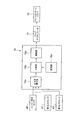
- the exhaust turbocharged engine 1 (hereinafter simply referred to as “engine 1”) is, as shown in FIG. 1, an exhaust heat recovery device 5 and an exhaust from the downstream side to the upstream side of the exhaust passage 3 of the engine 1.
- An exhaust turbine 11 of the turbocharger 10 is disposed.
- the exhaust heat recovery device 5 recovers the exhaust heat and discharges it to the outside.
- An exhaust gas bypass passage 14 bypassing the exhaust gas turbine 11 of the exhaust gas turbocharger 10 is connected between the exhaust gas turbocharger inlet of the exhaust passage 3 and the exhaust gas turbocharger outlet.
- the exhaust bypass passage 14 is provided with a waste gate valve 16 for opening and closing the exhaust bypass passage 14.
- a waste gate valve actuator 17 for driving the waste gate valve 16 to open and close the waste gate valve 16 is connected. The operation of the waste gate valve actuator 17 is performed by a waste gate valve controller 19 described later.
- an intake air cooler 21, a throttle valve 23, a compressor 12 of the exhaust gas turbocharger 10, and a mixer 25 are disposed from the downstream side to the upstream side of the intake passage 7 of the engine 1.
- the intake air cooler 21 cools the intake air and supplies it to the engine 1.
- the throttle valve 23 adjusts the flow rate of intake air.
- a throttle valve actuator 27 that adjusts the opening degree of the throttle valve 23 is connected to the throttle valve 23.
- the operation control of the throttle valve actuator 27 is performed by a throttle valve controller 30 described later.
- a gas amount control valve 33 is connected to the mixer 25.
- a mixed gas obtained by mixing the fuel gas from the fuel gas passage 35 connected to the gas amount control valve 33 and the intake air from the intake air passage 37 is an exhaust turbocharger. 10 supply to the compressor 12; Opening and closing control of the gas amount control valve 33 is performed by a gas amount control valve controller 40 described later.
- a first pressure sensor 42 for detecting the pressure of intake air in the intake passage 7a is provided in the intake passage 7a of the intake passage 7 between the throttle valve 23 and the compressor 12.
- the first pressure sensor 42, the second pressure sensor 43, and the intake air temperature sensor 44 are electrically connected to the waste gate valve controller 19 via the gas amount control valve controller 40.
- the engine 1 is attached with an engine speed sensor 47 for detecting an engine speed and an engine load sensor 48 for detecting an engine load.
- the engine speed sensor 47 and the engine load sensor 48 are electrically connected to the gas amount control valve controller 40.
- the engine 1 may be attached with a lubricating oil temperature sensor 49 described later that detects the temperature of the lubricating oil in the engine 1.
- the throttle valve controller 30 controls the throttle valve actuator 27 based on the detected value of the engine rotational speed from the engine rotational speed sensor 47 to control the opening degree of the throttle valve 23.
- the gas amount control valve controller 40 detects the intake pressure from the second pressure sensor 43, the intake temperature from the intake temperature sensor 44, and the engine rotational speed from the engine speed sensor 47. The air-fuel ratio is calculated, the opening degree of the gas amount control valve 33 corresponding to the air-fuel ratio of the engine is calculated, and the operation of the gas amount control valve 33 is controlled.
- the waste gate valve controller 19 calculates a pressure difference between the first pressure sensor 42 and the second pressure sensor 43 based on the pressure values detected by the first pressure sensor 42 and the second pressure sensor 43.
- the pressure difference calculated by the comparison unit 19 b that compares the pressure difference calculated by the calculation unit 19 a with the threshold set in advance, the storage unit 19 c that stores the threshold, and the comparison unit 19 b is smaller than the threshold
- the drive unit 19 d is operated to operate the waste gate valve 16 in the closing direction and to operate the waste gate valve 16 in the opening direction when the calculated pressure difference is larger than the threshold.
- the waste gate valve controller 19 is configured to operate when the engine 1 is started.
- an engine load sensor 48 is electrically connected to the pressure difference calculation unit 19a. Details of the engine load sensor 48 will be described later.
- the drive unit 19 d operates the waste gate valve actuator 17 in accordance with the control signal from the drive unit 19 d to open and close the waste gate valve 16.
- FIG. 3 shows the relationship between the flow rate of intake air and the degree of opening of the throttle valve 23 and the pressure difference across the throttle valve.
- the vertical axis of this graph indicates the flow rate of intake air
- the horizontal axis indicates the opening degree of the throttle valve 23 and the pressure difference before and after the throttle valve.
- the sensitivity to the flow rate is low when the opening degree of the throttle valve 23 is near the fully open position (near the arrow A). For this reason, when the throttle valve opening near the full opening is used for control, there is a possibility that the control accuracy may be reduced.
- the relationship between the pressure difference before and after the throttle valve and the flow rate is a linear relationship (the range indicated by arrow B)
- the sensitivity to the flow rate is high in the entire throttle valve opening range.
- the present invention utilizes the relationship between the pressure difference before and after the throttle valve and the flow rate.
- FIG. 4 and FIG. 5 the vertical axis shows the magnitude of various parameters (slot opening degree, engine load, engine speed, pressure difference ⁇ P), and the horizontal axis shows time.
- the throttle valve 23 controls the flow rate of intake air, but when the engine load (engine load) shown by the solid line rises sharply, the engine speed ( Since the engine rotation speed is lowered, the throttle valve 23 is opened to increase the intake amount.
- the pressure difference ⁇ P has a margin (the pressure difference is relatively large), the intake amount can be increased, and the responsiveness to load fluctuation can be further improved.
- the reason why the pressure difference ⁇ P once decreases and then gradually increases is because the intake turbocharging by the exhaust turbocharger 10 (see FIG. 1) catches up and the intake gradually becomes excessive. This is because the valve 23 is controlled to the closing side and the pressure difference ⁇ P is increased.
- a threshold value is set in the storage unit 19c (see FIG. 2) so as to satisfy the minimum pressure difference ⁇ P in which the rotational speed fluctuation of the engine 1 does not increase. It is done.
- the threshold Ps is set to have an upper threshold Psu having a control width as the threshold Ps and a lower threshold Psd.
- the throttle valve is on the open side in order to keep the rotational speed constant. For this reason, the pressure difference between the front and rear of the throttle valve becomes smaller than the upper threshold Psd, and the waste gate valve 16 operates to the closing side. Therefore, the load response can be secured without increasing the opening degree of the throttle valve 23.
- the threshold value Ps is fixed, but as shown in FIG. 1 and FIG. 7A, a change threshold value Ps ′ larger than the threshold value Ps may be set.
- the change threshold Ps ′ is set to be a linear function with respect to the engine load such that the threshold decreases as the load on the engine 1 increases.
- the change threshold Ps' is set as a linear function having a negative slope. In this way, for example, the opening degree of the waste gate valve 16 can be controlled on the small side in a low load area where the engine load is likely to fluctuate.
- the change threshold Ps ′ may be set as a map in the storage unit 19c (see FIG. 2).
- the change threshold Ps ' is set as a function of the engine load, but even if the change threshold Ps' is set as a function of the temperature of the lubricating oil in the engine 1 which is closely related to the engine load response.
- the engine 1 is provided with a lubricating oil temperature sensor 49 (see FIG. 1) for detecting the temperature of the lubricating oil, and this lubricating oil temperature sensor 49 is transmitted to the waste gate valve controller 19 via the gas amount control valve controller 40. Connect electrically.
Abstract
L'invention concerne un moteur à turbocompresseur d'échappement qui est pourvu : d'un passage de dérivation d'échappement qui est relié à un passage d'échappement et qui contourne une turbine du turbocompresseur d'échappement ; d'une soupape de décharge qui ouvre et ferme ce passage ; d'une soupape d'étranglement disposée sur un passage d'admission. Un premier capteur de pression et un second capteur de pression sont respectivement disposés sur le côté amont et le côté aval de la soupape d'étranglement du passage d'admission. De plus, un moyen de commande d'ouverture/fermeture de soupape est fourni pour calculer la différence de pression entre les valeurs de pression obtenues par le premier capteur de pression et le second capteur de pression, pour fermer la soupape de décharge lorsque la différence de pression est inférieure à un seuil, et pour ouvrir la soupape de décharge lorsque la différence de pression est supérieure au seuil.
Priority Applications (3)
| Application Number | Priority Date | Filing Date | Title |
|---|---|---|---|
| US16/064,223 US20190003375A1 (en) | 2015-12-25 | 2015-12-25 | Engine with exhaust turbocharger |
| PCT/JP2015/086294 WO2017109959A1 (fr) | 2015-12-25 | 2015-12-25 | Moteur à turbocompresseur d'échappement |
| EP15911396.8A EP3379052A4 (fr) | 2015-12-25 | 2015-12-25 | Moteur à turbocompresseur d'échappement |
Applications Claiming Priority (1)
| Application Number | Priority Date | Filing Date | Title |
|---|---|---|---|
| PCT/JP2015/086294 WO2017109959A1 (fr) | 2015-12-25 | 2015-12-25 | Moteur à turbocompresseur d'échappement |
Publications (1)
| Publication Number | Publication Date |
|---|---|
| WO2017109959A1 true WO2017109959A1 (fr) | 2017-06-29 |
Family
ID=59089829
Family Applications (1)
| Application Number | Title | Priority Date | Filing Date |
|---|---|---|---|
| PCT/JP2015/086294 WO2017109959A1 (fr) | 2015-12-25 | 2015-12-25 | Moteur à turbocompresseur d'échappement |
Country Status (3)
| Country | Link |
|---|---|
| US (1) | US20190003375A1 (fr) |
| EP (1) | EP3379052A4 (fr) |
| WO (1) | WO2017109959A1 (fr) |
Cited By (1)
| Publication number | Priority date | Publication date | Assignee | Title |
|---|---|---|---|---|
| CN114941557A (zh) * | 2022-05-09 | 2022-08-26 | 潍柴动力股份有限公司 | 发动机连接管路及控制方法、发动机系统 |
Families Citing this family (2)
| Publication number | Priority date | Publication date | Assignee | Title |
|---|---|---|---|---|
| US11193434B2 (en) * | 2019-11-29 | 2021-12-07 | Caterpillar Inc. | Turbocharger control using an intake throttle valve |
| CN114233489B (zh) * | 2021-12-22 | 2024-03-19 | 潍柴动力股份有限公司 | 一种增压废气旁通阀的驱动占空比确定方法及相关设备 |
Citations (5)
| Publication number | Priority date | Publication date | Assignee | Title |
|---|---|---|---|---|
| JPH04287835A (ja) * | 1991-03-19 | 1992-10-13 | Toyota Motor Corp | ターボチャージャの過給圧制御装置 |
| JP2007262968A (ja) * | 2006-03-28 | 2007-10-11 | Toyota Motor Corp | 加速要求判定装置及び制御装置 |
| JP2010014122A (ja) | 2009-09-08 | 2010-01-21 | Mitsubishi Heavy Ind Ltd | ウェストゲートバルブを備えた排気ターボ過給機付きエンジン及びその運転方法 |
| JP2012241625A (ja) * | 2011-05-19 | 2012-12-10 | Toyota Motor Corp | 過給エンジンの制御装置 |
| WO2013105226A1 (fr) * | 2012-01-11 | 2013-07-18 | トヨタ自動車株式会社 | Dispositif de commande pour moteur à combustion interne |
Family Cites Families (3)
| Publication number | Priority date | Publication date | Assignee | Title |
|---|---|---|---|---|
| DE2716470A1 (de) * | 1977-04-14 | 1978-10-19 | Daimler Benz Ag | Brennkraftmaschine mit einem abgasturbolader |
| JPS5569725A (en) * | 1978-11-18 | 1980-05-26 | Nissan Motor Co Ltd | Exhaust gas by-passing valve mechanism for use with exhaust turbo-supercharger |
| US6640754B1 (en) * | 2000-09-14 | 2003-11-04 | Yamaha Hatsudoki Kabushiki Kaisha | Ignition timing system for homogeneous charge compression engine |
-
2015
- 2015-12-25 WO PCT/JP2015/086294 patent/WO2017109959A1/fr active Application Filing
- 2015-12-25 EP EP15911396.8A patent/EP3379052A4/fr not_active Withdrawn
- 2015-12-25 US US16/064,223 patent/US20190003375A1/en not_active Abandoned
Patent Citations (5)
| Publication number | Priority date | Publication date | Assignee | Title |
|---|---|---|---|---|
| JPH04287835A (ja) * | 1991-03-19 | 1992-10-13 | Toyota Motor Corp | ターボチャージャの過給圧制御装置 |
| JP2007262968A (ja) * | 2006-03-28 | 2007-10-11 | Toyota Motor Corp | 加速要求判定装置及び制御装置 |
| JP2010014122A (ja) | 2009-09-08 | 2010-01-21 | Mitsubishi Heavy Ind Ltd | ウェストゲートバルブを備えた排気ターボ過給機付きエンジン及びその運転方法 |
| JP2012241625A (ja) * | 2011-05-19 | 2012-12-10 | Toyota Motor Corp | 過給エンジンの制御装置 |
| WO2013105226A1 (fr) * | 2012-01-11 | 2013-07-18 | トヨタ自動車株式会社 | Dispositif de commande pour moteur à combustion interne |
Non-Patent Citations (1)
| Title |
|---|
| See also references of EP3379052A4 * |
Cited By (1)
| Publication number | Priority date | Publication date | Assignee | Title |
|---|---|---|---|---|
| CN114941557A (zh) * | 2022-05-09 | 2022-08-26 | 潍柴动力股份有限公司 | 发动机连接管路及控制方法、发动机系统 |
Also Published As
| Publication number | Publication date |
|---|---|
| EP3379052A1 (fr) | 2018-09-26 |
| US20190003375A1 (en) | 2019-01-03 |
| EP3379052A4 (fr) | 2018-10-03 |
Similar Documents
| Publication | Publication Date | Title |
|---|---|---|
| US7905091B2 (en) | Method and device for controlling or regulating the boost pressure of an internal combustion engine having a compressor | |
| US8783029B2 (en) | Supercharged internal combustion engine and method for operating an internal combustion engine of said type | |
| US6662562B2 (en) | Method and device for regulating the boost pressure of an internal combustion engine | |
| US11692498B2 (en) | Internal combustion engine system and method for reduced turbo lag | |
| JP5389238B1 (ja) | 内燃機関のウェイストゲートバルブ制御装置 | |
| CN102758687B (zh) | 内燃机控制装置 | |
| US7908858B2 (en) | System that limits turbo speed by controlling fueling | |
| JP2010014122A (ja) | ウェストゲートバルブを備えた排気ターボ過給機付きエンジン及びその運転方法 | |
| JP2006266216A (ja) | ディーゼルエンジンの吸排気装置 | |
| CN103233825A (zh) | 二级可调增压控制系统及其控制方法 | |
| WO2017109959A1 (fr) | Moteur à turbocompresseur d'échappement | |
| JP6818513B2 (ja) | 車両のスーパーチャージャー制御方法及びその制御システム | |
| JP5800873B2 (ja) | 内燃機関の制御装置 | |
| EP3078830B1 (fr) | Appareil de commande pour un moteur à combustion interne avec un compresseur de suralimentation et un procédé pour commander la pression d'admission | |
| US10895207B2 (en) | Method of operating an engine assembly | |
| JPH0543860B2 (fr) | ||
| KR20110115533A (ko) | 질량 흐름을 개회로 제어하기 위한 플랩 액추에이터의 작동 방법 및 작동 장치와, 플랩 액추에이터 | |
| KR102223103B1 (ko) | 내연 기관의 가스 안내 시스템의 기본 부스트 압력을 결정하기 위한 방법 및 이와 같은 방법을 실행하기 위한 엔진 제어부 | |
| JP2016017431A (ja) | 排気ターボ過給機付きエンジン | |
| KR101513587B1 (ko) | 볼텍스 튜브를 이용하는 유로가변형 흡입공기 냉각장치 및 그 제어방법 | |
| JP6907977B2 (ja) | ターボチャージャの制御装置 | |
| US9273619B2 (en) | Supercharged engine and method of control | |
| JP4452163B2 (ja) | ウェストゲートバルブを備えた排気ターボ過給機付きエンジン及びその運転方法 | |
| US10634100B2 (en) | Control device for internal combustion engine | |
| JP5067268B2 (ja) | 過給機付きエンジンの過給圧制御装置 |
Legal Events
| Date | Code | Title | Description |
|---|---|---|---|
| 121 | Ep: the epo has been informed by wipo that ep was designated in this application |
Ref document number: 15911396 Country of ref document: EP Kind code of ref document: A1 |
|
| WWE | Wipo information: entry into national phase |
Ref document number: 2015911396 Country of ref document: EP |
|
| NENP | Non-entry into the national phase |
Ref country code: DE |
|
| ENP | Entry into the national phase |
Ref document number: 2015911396 Country of ref document: EP Effective date: 20180620 |
|
| NENP | Non-entry into the national phase |
Ref country code: JP |