WO2017109959A1 - Engine with exhaust turbocharger - Google Patents
Engine with exhaust turbocharger Download PDFInfo
- Publication number
- WO2017109959A1 WO2017109959A1 PCT/JP2015/086294 JP2015086294W WO2017109959A1 WO 2017109959 A1 WO2017109959 A1 WO 2017109959A1 JP 2015086294 W JP2015086294 W JP 2015086294W WO 2017109959 A1 WO2017109959 A1 WO 2017109959A1
- Authority
- WO
- WIPO (PCT)
- Prior art keywords
- engine
- threshold
- exhaust
- throttle valve
- opening
- Prior art date
Links
Images


Classifications
-
- F—MECHANICAL ENGINEERING; LIGHTING; HEATING; WEAPONS; BLASTING
- F02—COMBUSTION ENGINES; HOT-GAS OR COMBUSTION-PRODUCT ENGINE PLANTS
- F02B—INTERNAL-COMBUSTION PISTON ENGINES; COMBUSTION ENGINES IN GENERAL
- F02B37/00—Engines characterised by provision of pumps driven at least for part of the time by exhaust
- F02B37/12—Control of the pumps
- F02B37/18—Control of the pumps by bypassing exhaust from the inlet to the outlet of turbine or to the atmosphere
- F02B37/183—Arrangements of bypass valves or actuators therefor
- F02B37/186—Arrangements of actuators or linkage for bypass valves
-
- F—MECHANICAL ENGINEERING; LIGHTING; HEATING; WEAPONS; BLASTING
- F02—COMBUSTION ENGINES; HOT-GAS OR COMBUSTION-PRODUCT ENGINE PLANTS
- F02D—CONTROLLING COMBUSTION ENGINES
- F02D23/00—Controlling engines characterised by their being supercharged
-
- F—MECHANICAL ENGINEERING; LIGHTING; HEATING; WEAPONS; BLASTING
- F02—COMBUSTION ENGINES; HOT-GAS OR COMBUSTION-PRODUCT ENGINE PLANTS
- F02D—CONTROLLING COMBUSTION ENGINES
- F02D41/00—Electrical control of supply of combustible mixture or its constituents
- F02D41/0002—Controlling intake air
- F02D41/0007—Controlling intake air for control of turbo-charged or super-charged engines
-
- F—MECHANICAL ENGINEERING; LIGHTING; HEATING; WEAPONS; BLASTING
- F02—COMBUSTION ENGINES; HOT-GAS OR COMBUSTION-PRODUCT ENGINE PLANTS
- F02D—CONTROLLING COMBUSTION ENGINES
- F02D19/00—Controlling engines characterised by their use of non-liquid fuels, pluralities of fuels, or non-fuel substances added to the combustible mixtures
- F02D19/02—Controlling engines characterised by their use of non-liquid fuels, pluralities of fuels, or non-fuel substances added to the combustible mixtures peculiar to engines working with gaseous fuels
- F02D19/021—Control of components of the fuel supply system
- F02D19/023—Control of components of the fuel supply system to adjust the fuel mass or volume flow
-
- F—MECHANICAL ENGINEERING; LIGHTING; HEATING; WEAPONS; BLASTING
- F02—COMBUSTION ENGINES; HOT-GAS OR COMBUSTION-PRODUCT ENGINE PLANTS
- F02D—CONTROLLING COMBUSTION ENGINES
- F02D2200/00—Input parameters for engine control
- F02D2200/02—Input parameters for engine control the parameters being related to the engine
- F02D2200/04—Engine intake system parameters
- F02D2200/0406—Intake manifold pressure
-
- F—MECHANICAL ENGINEERING; LIGHTING; HEATING; WEAPONS; BLASTING
- F02—COMBUSTION ENGINES; HOT-GAS OR COMBUSTION-PRODUCT ENGINE PLANTS
- F02D—CONTROLLING COMBUSTION ENGINES
- F02D41/00—Electrical control of supply of combustible mixture or its constituents
- F02D41/0025—Controlling engines characterised by use of non-liquid fuels, pluralities of fuels, or non-fuel substances added to the combustible mixtures
- F02D41/0027—Controlling engines characterised by use of non-liquid fuels, pluralities of fuels, or non-fuel substances added to the combustible mixtures the fuel being gaseous
-
- F—MECHANICAL ENGINEERING; LIGHTING; HEATING; WEAPONS; BLASTING
- F05—INDEXING SCHEMES RELATING TO ENGINES OR PUMPS IN VARIOUS SUBCLASSES OF CLASSES F01-F04
- F05D—INDEXING SCHEME FOR ASPECTS RELATING TO NON-POSITIVE-DISPLACEMENT MACHINES OR ENGINES, GAS-TURBINES OR JET-PROPULSION PLANTS
- F05D2220/00—Application
- F05D2220/40—Application in turbochargers
-
- Y—GENERAL TAGGING OF NEW TECHNOLOGICAL DEVELOPMENTS; GENERAL TAGGING OF CROSS-SECTIONAL TECHNOLOGIES SPANNING OVER SEVERAL SECTIONS OF THE IPC; TECHNICAL SUBJECTS COVERED BY FORMER USPC CROSS-REFERENCE ART COLLECTIONS [XRACs] AND DIGESTS
- Y02—TECHNOLOGIES OR APPLICATIONS FOR MITIGATION OR ADAPTATION AGAINST CLIMATE CHANGE
- Y02T—CLIMATE CHANGE MITIGATION TECHNOLOGIES RELATED TO TRANSPORTATION
- Y02T10/00—Road transport of goods or passengers
- Y02T10/10—Internal combustion engine [ICE] based vehicles
- Y02T10/12—Improving ICE efficiencies
Definitions
- the present disclosure mainly applies to a four-stroke gas engine, and an exhaust bypass passage connected to a turbocharger outlet by bypassing a turbine from an exhaust turbocharger inlet of an exhaust passage, and an engine opening and closing the exhaust bypass passage
- the present invention relates to an exhaust turbocharged engine provided with a waste gate valve for adjusting the output.
- An exhaust turbocharged engine which is capable of adjusting the amount of inflow to a turbine by diverting a part of exhaust gas in order to adjust the supply of supercharging pressure to the engine by the exhaust turbocharger. ing.
- an exhaust that bypasses a turbine by connecting between an exhaust turbocharger inlet of an exhaust passage and a turbocharger outlet.
- a bypass passage is provided, and the exhaust bypass passage is provided with a waste gate valve for opening and closing the passage.
- a throttle valve is provided in an intake passage for supplying intake air to the exhaust turbocharged engine. In the throttle valve, the opening degree of the throttle valve is adjusted based on a detection value of an engine rotation number detector that detects an engine rotation number.
- the temperature of intake air to the engine intake temperature
- the humidity of intake air intake humidity
- the opening degree of the throttle valve is smaller than that in summer and the like where the suction temperature and the suction humidity become high in order to keep the excess air ratio at a constant target value. If this is done, there is a possibility that the pump loss in the cylinder may increase and the thermal efficiency may decrease, particularly during high load and high revolution operations.
- the minimum allowable opening of the throttle valve that can suppress the increase in pump loss in the cylinder is set, and the opening of the throttle valve is the minimum allowable opening at the time of operation where intake temperature and intake humidity to the engine decrease. If it becomes smaller, the degree of opening of the waste gate valve is increased to decrease the flow rate of exhaust gas acting on the exhaust turbine of the exhaust turbocharger. Therefore, the amount of intake air supplied from the compressor of the exhaust turbocharger to the engine decreases to reduce the engine speed, and the opening degree of the throttle valve increases to maintain the engine speed at the target speed. Therefore, during high load and high revolution operation of the engine, the engine can be normally operated without reducing the opening of the throttle valve, and increase of pump loss in the cylinder is avoided during high load and high revolution operation. It is possible to prevent the reduction of the thermal efficiency.
- the opening degree of the throttle valve is maintained in order to maintain the excess air ratio at a constant target value during operation where the intake temperature and intake humidity to the engine become low. Is set to the fully open position or the opening degree in the vicinity, and the opening degree of the waste gate valve is controlled so that the difference between the measured value of the excess air ratio of the engine and the target value of the excess air ratio becomes small. .
- the opening degree of the throttle valve can be kept large and the engine can be operated normally with a required excess air ratio, and at high load and high revolution operation, An increase in pump loss in the cylinder can be avoided, and a decrease in thermal efficiency can be prevented.
- the throttle valve has a role of adjusting the intake pressure downstream of the throttle valve in the intake passage
- the relationship between the throttle valve opening and the pressure loss caused by the throttle valve is not linear.
- the sensitivity of the relationship between the throttle valve opening and the pressure loss due to the throttle valve is low when the throttle valve opening is near full opening, so if the throttle valve opening near the full opening is used for control, the desired excess air ratio is achieved. The accuracy may be reduced.
- the throttle valve has a solid difference, and even when the throttle valve opening degree is constant, the pressure loss caused by the throttle valve may not be constant, and the necessary load response can not be ensured. In addition, the pumping efficiency may be reduced more than necessary.
- the pressure loss due to the throttle valve is affected by the flow rate of intake air as well as the throttle valve opening degree, so even when the throttle valve opening degree is constant, the pressure loss at the throttle valve does not become constant. There is a case. As a result, the necessary load response can not be secured, and the pumping efficiency may be reduced more than necessary.
- At least some embodiments of the present invention can ensure necessary load responsiveness regardless of the size of the opening of the throttle valve and the individual differences of the throttle valve, and more than necessary It is an object of the present invention to provide an exhaust turbocharged engine which does not have the possibility of reducing the pumping efficiency.
- An exhaust turbocharged engine comprises An exhaust bypass passage connected to the exhaust turbocharger from the exhaust turbocharger inlet of the exhaust passage, bypassing the turbine of the exhaust turbocharger; A waste gate valve that adjusts the engine output by opening and closing the exhaust bypass passage; A throttle valve for controlling an intake amount to the engine in an intake passage between the exhaust turbocharger and the engine; A first pressure sensor and a second pressure sensor provided upstream and downstream of the throttle valve in the intake passage for detecting an intake pressure in the intake passage; These pressure differences are calculated based on pressure values detected by the first pressure sensor and the second pressure sensor, and when the calculated pressure difference is smaller than a preset threshold value, the waste gate valve is used. And a valve opening / closing control means for opening the waste gate valve when the closing operation is performed and the calculated pressure difference is larger than the threshold value.
- the throttle valve when the amount of intake air is insufficient, the throttle valve is opened in order to keep the engine speed constant. Therefore, the pressure difference across the throttle valve becomes smaller than the threshold, and the waste gate valve operates in the closing direction. Therefore, the load response can be secured without increasing the opening degree of the throttle valve.
- the throttle valve when the intake amount is excessive, the throttle valve is closed in order to keep the engine speed constant. For this reason, the pressure difference between the front and rear of the throttle valve becomes larger than the threshold, and the waste gate valve operates open. Therefore, an increase in pump loss can be avoided without reducing the opening degree of the throttle valve.
- the threshold is set to be constant in a region where the engine load is large, and is set to a threshold larger than the constant threshold in a region where the engine load is small.
- the valve opening / closing control means controls the opening of the waste gate valve to be smaller in a region where the threshold is larger than the constant threshold, and the region where the threshold is constant makes the opening of the waste gate valve large. Configured to control.
- the valve opening / closing control means controls the opening of the waste gate valve in a smaller direction in a region where the threshold is larger than a certain threshold, and in the region where the threshold is constant, the opening of the waste gate valve. Since the control is performed so as to be present in the large direction, for example, the opening degree of the waste gate valve can be controlled on the small side in the low load area where the engine load is likely to fluctuate. For this reason, since the supercharging pressure of the intake by the supercharger is high and the intake amount adjustment allowance by the throttle valve is large, it is possible to secure the load responsiveness according to the load fluctuation.
- the opening of the waste gate valve can be controlled on the large side in the high load area where the engine load is likely to be constant, the charge pressure of the intake air by the supercharger can be reduced to more than necessary. The possibility of reducing the pumping efficiency can be reduced.
- the threshold of the region where the threshold is larger than a certain threshold is configured to be preset as a function or a map with the load of the engine such that the threshold decreases as the engine load increases.
- the modification threshold is configured such that the threshold in the region where the threshold is greater than a certain threshold is preset as a function or map with the engine load such that the threshold decreases as the engine load increases. Therefore, for example, when the engine load gradually increases in a low load area where the engine load is likely to fluctuate, it is possible to more reliably ensure the load responsiveness according to the load fluctuation.
- the threshold of the region where the threshold is greater than a certain threshold is a function or a map of the engine oil temperature such that the threshold decreases as the oil temperature increases. It is configured as being preset.
- the opening degree of the waste gate valve can be controlled on the small side in the region where the lubricant response is poor, and the engine load response is low. For this reason, the load responsiveness can be compensated because the supercharging pressure of the intake air by the supercharger is high and the intake amount adjustment allowance by the throttle valve is large.
- the required load response can be secured regardless of the size of the opening of the throttle valve and the individual differences of the throttle valve, and the pumping loss is increased more than necessary. It is possible to provide an exhaust turbocharged engine that does not have the risk of causing
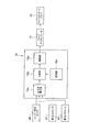
- the exhaust turbocharged engine 1 (hereinafter simply referred to as “engine 1”) is, as shown in FIG. 1, an exhaust heat recovery device 5 and an exhaust from the downstream side to the upstream side of the exhaust passage 3 of the engine 1.
- An exhaust turbine 11 of the turbocharger 10 is disposed.
- the exhaust heat recovery device 5 recovers the exhaust heat and discharges it to the outside.
- An exhaust gas bypass passage 14 bypassing the exhaust gas turbine 11 of the exhaust gas turbocharger 10 is connected between the exhaust gas turbocharger inlet of the exhaust passage 3 and the exhaust gas turbocharger outlet.
- the exhaust bypass passage 14 is provided with a waste gate valve 16 for opening and closing the exhaust bypass passage 14.
- a waste gate valve actuator 17 for driving the waste gate valve 16 to open and close the waste gate valve 16 is connected. The operation of the waste gate valve actuator 17 is performed by a waste gate valve controller 19 described later.
- an intake air cooler 21, a throttle valve 23, a compressor 12 of the exhaust gas turbocharger 10, and a mixer 25 are disposed from the downstream side to the upstream side of the intake passage 7 of the engine 1.
- the intake air cooler 21 cools the intake air and supplies it to the engine 1.
- the throttle valve 23 adjusts the flow rate of intake air.
- a throttle valve actuator 27 that adjusts the opening degree of the throttle valve 23 is connected to the throttle valve 23.
- the operation control of the throttle valve actuator 27 is performed by a throttle valve controller 30 described later.
- a gas amount control valve 33 is connected to the mixer 25.
- a mixed gas obtained by mixing the fuel gas from the fuel gas passage 35 connected to the gas amount control valve 33 and the intake air from the intake air passage 37 is an exhaust turbocharger. 10 supply to the compressor 12; Opening and closing control of the gas amount control valve 33 is performed by a gas amount control valve controller 40 described later.
- a first pressure sensor 42 for detecting the pressure of intake air in the intake passage 7a is provided in the intake passage 7a of the intake passage 7 between the throttle valve 23 and the compressor 12.
- the first pressure sensor 42, the second pressure sensor 43, and the intake air temperature sensor 44 are electrically connected to the waste gate valve controller 19 via the gas amount control valve controller 40.
- the engine 1 is attached with an engine speed sensor 47 for detecting an engine speed and an engine load sensor 48 for detecting an engine load.
- the engine speed sensor 47 and the engine load sensor 48 are electrically connected to the gas amount control valve controller 40.
- the engine 1 may be attached with a lubricating oil temperature sensor 49 described later that detects the temperature of the lubricating oil in the engine 1.
- the throttle valve controller 30 controls the throttle valve actuator 27 based on the detected value of the engine rotational speed from the engine rotational speed sensor 47 to control the opening degree of the throttle valve 23.
- the gas amount control valve controller 40 detects the intake pressure from the second pressure sensor 43, the intake temperature from the intake temperature sensor 44, and the engine rotational speed from the engine speed sensor 47. The air-fuel ratio is calculated, the opening degree of the gas amount control valve 33 corresponding to the air-fuel ratio of the engine is calculated, and the operation of the gas amount control valve 33 is controlled.
- the waste gate valve controller 19 calculates a pressure difference between the first pressure sensor 42 and the second pressure sensor 43 based on the pressure values detected by the first pressure sensor 42 and the second pressure sensor 43.
- the pressure difference calculated by the comparison unit 19 b that compares the pressure difference calculated by the calculation unit 19 a with the threshold set in advance, the storage unit 19 c that stores the threshold, and the comparison unit 19 b is smaller than the threshold
- the drive unit 19 d is operated to operate the waste gate valve 16 in the closing direction and to operate the waste gate valve 16 in the opening direction when the calculated pressure difference is larger than the threshold.
- the waste gate valve controller 19 is configured to operate when the engine 1 is started.
- an engine load sensor 48 is electrically connected to the pressure difference calculation unit 19a. Details of the engine load sensor 48 will be described later.
- the drive unit 19 d operates the waste gate valve actuator 17 in accordance with the control signal from the drive unit 19 d to open and close the waste gate valve 16.
- FIG. 3 shows the relationship between the flow rate of intake air and the degree of opening of the throttle valve 23 and the pressure difference across the throttle valve.
- the vertical axis of this graph indicates the flow rate of intake air
- the horizontal axis indicates the opening degree of the throttle valve 23 and the pressure difference before and after the throttle valve.
- the sensitivity to the flow rate is low when the opening degree of the throttle valve 23 is near the fully open position (near the arrow A). For this reason, when the throttle valve opening near the full opening is used for control, there is a possibility that the control accuracy may be reduced.
- the relationship between the pressure difference before and after the throttle valve and the flow rate is a linear relationship (the range indicated by arrow B)
- the sensitivity to the flow rate is high in the entire throttle valve opening range.
- the present invention utilizes the relationship between the pressure difference before and after the throttle valve and the flow rate.
- FIG. 4 and FIG. 5 the vertical axis shows the magnitude of various parameters (slot opening degree, engine load, engine speed, pressure difference ⁇ P), and the horizontal axis shows time.
- the throttle valve 23 controls the flow rate of intake air, but when the engine load (engine load) shown by the solid line rises sharply, the engine speed ( Since the engine rotation speed is lowered, the throttle valve 23 is opened to increase the intake amount.
- the pressure difference ⁇ P has a margin (the pressure difference is relatively large), the intake amount can be increased, and the responsiveness to load fluctuation can be further improved.
- the reason why the pressure difference ⁇ P once decreases and then gradually increases is because the intake turbocharging by the exhaust turbocharger 10 (see FIG. 1) catches up and the intake gradually becomes excessive. This is because the valve 23 is controlled to the closing side and the pressure difference ⁇ P is increased.
- a threshold value is set in the storage unit 19c (see FIG. 2) so as to satisfy the minimum pressure difference ⁇ P in which the rotational speed fluctuation of the engine 1 does not increase. It is done.
- the threshold Ps is set to have an upper threshold Psu having a control width as the threshold Ps and a lower threshold Psd.
- the throttle valve is on the open side in order to keep the rotational speed constant. For this reason, the pressure difference between the front and rear of the throttle valve becomes smaller than the upper threshold Psd, and the waste gate valve 16 operates to the closing side. Therefore, the load response can be secured without increasing the opening degree of the throttle valve 23.
- the threshold value Ps is fixed, but as shown in FIG. 1 and FIG. 7A, a change threshold value Ps ′ larger than the threshold value Ps may be set.
- the change threshold Ps ′ is set to be a linear function with respect to the engine load such that the threshold decreases as the load on the engine 1 increases.
- the change threshold Ps' is set as a linear function having a negative slope. In this way, for example, the opening degree of the waste gate valve 16 can be controlled on the small side in a low load area where the engine load is likely to fluctuate.
- the change threshold Ps ′ may be set as a map in the storage unit 19c (see FIG. 2).
- the change threshold Ps ' is set as a function of the engine load, but even if the change threshold Ps' is set as a function of the temperature of the lubricating oil in the engine 1 which is closely related to the engine load response.
- the engine 1 is provided with a lubricating oil temperature sensor 49 (see FIG. 1) for detecting the temperature of the lubricating oil, and this lubricating oil temperature sensor 49 is transmitted to the waste gate valve controller 19 via the gas amount control valve controller 40. Connect electrically.
Landscapes
- Engineering & Computer Science (AREA)
- Chemical & Material Sciences (AREA)
- Combustion & Propulsion (AREA)
- Mechanical Engineering (AREA)
- General Engineering & Computer Science (AREA)
- Supercharger (AREA)
Abstract
This engine with an exhaust turbocharger is provided with: an exhaust bypass passage that is connected to an exhaust passage and bypasses a turbine of the exhaust turbocharger; a waist gate valve that opens and closes this passage; and a throttle valve provided to an intake passage. A first pressure sensor and a second pressure sensor are respectively provided on the upstream side and the downstream side of the throttle valve of the intake passage. In addition, a valve opening/closing control means is provided that calculates the pressure difference between pressure values obtained from the first pressure sensor and the second pressure sensor, closes the waist gate valve when the pressure difference is less than a threshold, and opens the waist gate valve when the pressure difference is greater than the threshold.
Description
本開示は、主として4サイクルガスエンジンに適用され、排気通路の排気ターボ過給機入口からタービンをバイパスして過給機出口に接続される排気バイパス通路と、該排気バイパス通路を開閉してエンジン出力を調整するウェイストゲートバルブとを備えた排気ターボ過給機付きエンジンに関する。
The present disclosure mainly applies to a four-stroke gas engine, and an exhaust bypass passage connected to a turbocharger outlet by bypassing a turbine from an exhaust turbocharger inlet of an exhaust passage, and an engine opening and closing the exhaust bypass passage The present invention relates to an exhaust turbocharged engine provided with a waste gate valve for adjusting the output.
排気ターボ過給機によるエンジンへの過給圧の供給を調整等するために、排気ガスの一部を分流させることによりタービンへの流入量を調節可能な排気ターボ過給機付きエンジンが知られている。
An exhaust turbocharged engine is known which is capable of adjusting the amount of inflow to a turbine by diverting a part of exhaust gas in order to adjust the supply of supercharging pressure to the engine by the exhaust turbocharger. ing.
このような排気ターボ過給機付きエンジンには、例えば特許文献1に記載されているように、排気通路の排気ターボ過給機入口と過給機出口との間を繋いでタービンをバイパスする排気バイパス通路が設けられ、この排気バイパス通路にこの通路を開閉するウェイストゲートバルブが設けられている。排気ターボ過給機付きエンジンに吸気を供給する吸気通路には、スロットルバルブが設けられている。スロットルバルブは、エンジン回転数を検出するエンジン回転数検出器の検出値に基づいてスロットルバルブの開度が調整されるようになっている。
In such an exhaust turbocharged engine, as described in, for example, Patent Document 1, an exhaust that bypasses a turbine by connecting between an exhaust turbocharger inlet of an exhaust passage and a turbocharger outlet. A bypass passage is provided, and the exhaust bypass passage is provided with a waste gate valve for opening and closing the passage. A throttle valve is provided in an intake passage for supplying intake air to the exhaust turbocharged engine. In the throttle valve, the opening degree of the throttle valve is adjusted based on a detection value of an engine rotation number detector that detects an engine rotation number.
このようなスロットルバルブが設けられた排気ターボ過給機付きエンジンでは、冬季や寒冷地での運転時のような、エンジンへの吸入空気の温度(吸入温度)や吸入空気の湿度(吸入湿度)が低くなる運転時には、空気密度の増加によって排気ターボ過給機の過給圧力つまり吸気圧力が高くなる。従って、吸入温度や吸入湿度が低くなる運転時には、空気過剰率を一定の目標値に保持するために、スロットルバルブの開度を吸入温度や吸入湿度が高くなる夏季等での運転時に比べて小さくする必要があるが、このようにすると、特に高負荷、高回転運転時において、シリンダ内のポンプ損失が増大して熱効率が低下する虞が生じる。
In an exhaust turbocharged engine provided with such a throttle valve, the temperature of intake air to the engine (intake temperature) or the humidity of intake air (intake humidity) as in winter or during operation in a cold region During operation, when the air pressure becomes lower, the boost pressure or intake pressure of the exhaust turbocharger becomes higher due to the increase of the air density. Therefore, when the suction temperature and the suction humidity are low, the opening degree of the throttle valve is smaller than that in summer and the like where the suction temperature and the suction humidity become high in order to keep the excess air ratio at a constant target value. If this is done, there is a possibility that the pump loss in the cylinder may increase and the thermal efficiency may decrease, particularly during high load and high revolution operations.
そこで、シリンダ内のポンプ損失の増大を抑制できるスロットルバルブの許容最小開度を設定しておき、エンジンへの吸入温度や吸入湿度が低くなる運転時等において、スロットルバルブの開度が許容最小開度よりも小さくなると、ウェイストゲートバルブの開度を増加させて、排気ターボ過給機の排気タービンに作用する排気ガス流量を減少させる。したがって、排気ターボ過給機のコンプレッサからエンジンに供給される吸気量が減少してエンジン回転数が低下し、エンジン回転数を目標回転数に維持するためにスロットルバルブの開度が増加する。このため、エンジンの高負荷、高回転運転時に、スロットルバルブの開度を小さくすることなくエンジンを正常運転することができ、高負荷、高回転運転時において、シリンダ内のポンプ損失の増大を回避でき熱効率の低下を防止することができる。
Therefore, the minimum allowable opening of the throttle valve that can suppress the increase in pump loss in the cylinder is set, and the opening of the throttle valve is the minimum allowable opening at the time of operation where intake temperature and intake humidity to the engine decrease. If it becomes smaller, the degree of opening of the waste gate valve is increased to decrease the flow rate of exhaust gas acting on the exhaust turbine of the exhaust turbocharger. Therefore, the amount of intake air supplied from the compressor of the exhaust turbocharger to the engine decreases to reduce the engine speed, and the opening degree of the throttle valve increases to maintain the engine speed at the target speed. Therefore, during high load and high revolution operation of the engine, the engine can be normally operated without reducing the opening of the throttle valve, and increase of pump loss in the cylinder is avoided during high load and high revolution operation. It is possible to prevent the reduction of the thermal efficiency.
また、特許文献1に記載の排気ターボ過給機付きエンジンでは、エンジンへの吸入温度や吸入湿度が低くなる運転時に、空気過剰率を一定の目標値に保持するために、スロットルバルブの開度を全開あるいはその近傍の開度になるように設定しておき、エンジンの空気過剰率の実測値と空気過剰率の目標値との差が小さくなるように、ウェイストゲートバルブの開度を制御する。これにより、エンジンの高負荷、高回転運転時に、スロットルバルブの開度を大きく保持してエンジンを所要の空気過剰率で以って正常運転することができ、高負荷、高回転運転時において、シリンダ内のポンプ損失の増大を回避でき熱効率の低下を防止することができる。
Further, in the engine with an exhaust turbo charger described in Patent Document 1, the opening degree of the throttle valve is maintained in order to maintain the excess air ratio at a constant target value during operation where the intake temperature and intake humidity to the engine become low. Is set to the fully open position or the opening degree in the vicinity, and the opening degree of the waste gate valve is controlled so that the difference between the measured value of the excess air ratio of the engine and the target value of the excess air ratio becomes small. . As a result, at high load and high revolution operation of the engine, the opening degree of the throttle valve can be kept large and the engine can be operated normally with a required excess air ratio, and at high load and high revolution operation, An increase in pump loss in the cylinder can be avoided, and a decrease in thermal efficiency can be prevented.
しかしながら、スロットルバルブは、吸気通路においてスロットルバルブよりも下流側の吸気圧力を調整する役割を担っているが、スロットルバルブ開度とスロットルバルブに起因する圧力損失との関係はリニアな関係ではなく、特にスロットルバルブ開度が全開付近ではスロットルバルブ開度とスロットルバルブに起因する圧力損失との関係の感度が低いため、全開付近のスロットルバルブ開度を制御に用いると、所望の空気過剰率にする精度が低下する虞がある。
However, although the throttle valve has a role of adjusting the intake pressure downstream of the throttle valve in the intake passage, the relationship between the throttle valve opening and the pressure loss caused by the throttle valve is not linear. In particular, the sensitivity of the relationship between the throttle valve opening and the pressure loss due to the throttle valve is low when the throttle valve opening is near full opening, so if the throttle valve opening near the full opening is used for control, the desired excess air ratio is achieved. The accuracy may be reduced.
また、スロットルバルブは、固体差があり、スロットルバルブ開度を一定にした場合でも、スロットルバルブに起因する圧力損失が一定にならない場合があり、必要な負荷応答性を確保することができず、また必要以上にポンピング効率を低下させる虞が生じる。
Further, the throttle valve has a solid difference, and even when the throttle valve opening degree is constant, the pressure loss caused by the throttle valve may not be constant, and the necessary load response can not be ensured. In addition, the pumping efficiency may be reduced more than necessary.
また、スロットルバルブに起因する圧力損失は、スロットルバルブ開度の他に、吸気の流量等の影響を受けるので、スロットルバルブ開度を一定にした場合でも、スロットルバルブでの圧力損失が一定とならない場合がある。このため、必要な負荷応答性を確保することができず、また必要以上にポンピング効率を低下させる虞が生じる。
In addition, the pressure loss due to the throttle valve is affected by the flow rate of intake air as well as the throttle valve opening degree, so even when the throttle valve opening degree is constant, the pressure loss at the throttle valve does not become constant. There is a case. As a result, the necessary load response can not be secured, and the pumping efficiency may be reduced more than necessary.
上述の事情に鑑みて、本発明の少なくとも幾つかの実施形態は、スロットルバルブの開度の大きさやスロットルバルブの個体差に関係なく、必要な負荷応答性を確保することができ、また必要以上にポンピング効率を低下させる虞がない排気ターボ過給機付きエンジンを提供することを目的とする。
In view of the above-mentioned circumstances, at least some embodiments of the present invention can ensure necessary load responsiveness regardless of the size of the opening of the throttle valve and the individual differences of the throttle valve, and more than necessary It is an object of the present invention to provide an exhaust turbocharged engine which does not have the possibility of reducing the pumping efficiency.
本発明の幾つかの実施形態に係わる排気ターボ過給機付きエンジンは、
排気通路の排気ターボ過給機入口から該排気ターボ過給機のタービンをバイパスして前記排気ターボ過給機出口に接続される排気バイパス通路と、
前記排気バイパス通路を開閉してエンジン出力を調整するウェイストゲートバルブと、
前記排気ターボ過給機とエンジンとの間の吸気通路に該エンジンへの吸気量を制御するスロットルバルブと、
前記吸気通路の前記スロットルバルブよりも上流側及び下流側に設けられ、前記吸気通路中の吸気圧力を検出する第1圧力センサ及び第2圧力センサと、
前記第1圧力センサ及び前記第2圧力センサにより検出された圧力値に基づいてこれらの圧力差を算出し、この算出された圧力差が予め設定された閾値よりも小さいときには、前記ウェイストゲートバルブを閉作動させ、前記算出された圧力差が前記閾値よりも大きいときには、前記ウェイストゲートバルブを開作動させるバルブ開閉制御手段と、を備えるように構成される。 An exhaust turbocharged engine according to some embodiments of the invention comprises
An exhaust bypass passage connected to the exhaust turbocharger from the exhaust turbocharger inlet of the exhaust passage, bypassing the turbine of the exhaust turbocharger;
A waste gate valve that adjusts the engine output by opening and closing the exhaust bypass passage;
A throttle valve for controlling an intake amount to the engine in an intake passage between the exhaust turbocharger and the engine;
A first pressure sensor and a second pressure sensor provided upstream and downstream of the throttle valve in the intake passage for detecting an intake pressure in the intake passage;
These pressure differences are calculated based on pressure values detected by the first pressure sensor and the second pressure sensor, and when the calculated pressure difference is smaller than a preset threshold value, the waste gate valve is used. And a valve opening / closing control means for opening the waste gate valve when the closing operation is performed and the calculated pressure difference is larger than the threshold value.
上記排気ターボ過給機付きエンジンによれば、吸気量が不足な場合、エンジン回転数を一定に保持するため、スロットルバルブが開側となる。このため、スロットルバルブ前後の圧力差は閾値よりも小さくなり、ウェイストゲートバルブは閉側に作動する。このため、スロットルバルブの開度を大きくすることなく、負荷応答性を確保することができる。また、吸気量が余剰な場合、エンジン回転数を一定に保持するため、スロットルバルブが閉側となる。このため、スロットルバルブ前後の圧力差は閾値よりも大きくなり、ウェイストゲートバルブは開側に作動する。このため、スロットルバルブの開度を小さくすることなく、ポンプ損失の増大を回避することができる。
According to the above exhaust turbo-supercharger-equipped engine, when the amount of intake air is insufficient, the throttle valve is opened in order to keep the engine speed constant. Therefore, the pressure difference across the throttle valve becomes smaller than the threshold, and the waste gate valve operates in the closing direction. Therefore, the load response can be secured without increasing the opening degree of the throttle valve. In addition, when the intake amount is excessive, the throttle valve is closed in order to keep the engine speed constant. For this reason, the pressure difference between the front and rear of the throttle valve becomes larger than the threshold, and the waste gate valve operates open. Therefore, an increase in pump loss can be avoided without reducing the opening degree of the throttle valve.
また、幾つかの実施形態では、
前記閾値は、エンジン負荷が大きい域では一定に設定され、前記エンジン負荷が小さい域では前記一定の閾値よりも大きな閾値に設定され、
前記バルブ開閉制御手段は、前記閾値が前記一定の閾値よりも大きくなる域では前記ウェイストゲートバルブの開度を小さくするように制御し、前記閾値が一定する域はウェイストゲートバルブの開度を大きくするように制御するように構成される。 Also, in some embodiments,
The threshold is set to be constant in a region where the engine load is large, and is set to a threshold larger than the constant threshold in a region where the engine load is small.
The valve opening / closing control means controls the opening of the waste gate valve to be smaller in a region where the threshold is larger than the constant threshold, and the region where the threshold is constant makes the opening of the waste gate valve large. Configured to control.
この場合、バルブ開閉制御手段は、閾値が一定の閾値よりも大きくなる域ではウェイストゲートバルブの開度を小さい方向に存在させるように制御し、閾値が一定する域はウェイストゲートバルブの開度を大きい方向に存在させるように制御するので、例えば、機関負荷が変動する可能性が高い低負荷域において、ウェイストゲートバルブの開度を小さい側で制御することができる。このため、過給機による吸気の過給圧が高くスロットル弁での吸気量調整代が大きいため負荷変動に応じた負荷応答性を確保することができる。また、機関負荷が一定となる可能性の高い高負荷域では、ウェイストゲートバルブの開度を大きい側で制御することができるので、過給機による吸気の過給圧を減少させて必要以上にポンピング効率を低下させる虞が少なくすることができる。
In this case, the valve opening / closing control means controls the opening of the waste gate valve in a smaller direction in a region where the threshold is larger than a certain threshold, and in the region where the threshold is constant, the opening of the waste gate valve. Since the control is performed so as to be present in the large direction, for example, the opening degree of the waste gate valve can be controlled on the small side in the low load area where the engine load is likely to fluctuate. For this reason, since the supercharging pressure of the intake by the supercharger is high and the intake amount adjustment allowance by the throttle valve is large, it is possible to secure the load responsiveness according to the load fluctuation. In addition, since the opening of the waste gate valve can be controlled on the large side in the high load area where the engine load is likely to be constant, the charge pressure of the intake air by the supercharger can be reduced to more than necessary. The possibility of reducing the pumping efficiency can be reduced.
また、幾つかの実施形態では、
前記閾値が一定の閾値よりも大きくなる域の閾値は、前記エンジン負荷が増大するに従って前記閾値が減少するような前記エンジンの負荷との関数又はマップとして予め設定されているように構成される。 Also, in some embodiments,
The threshold of the region where the threshold is larger than a certain threshold is configured to be preset as a function or a map with the load of the engine such that the threshold decreases as the engine load increases.
この場合、変更閾値は、閾値が一定の閾値よりも大きくなる域の閾値は、エンジン負荷が増大するに従って閾値が減少するようなエンジンの負荷との関数又はマップとして予め設定されているように構成されるので、例えば、機関負荷が変動する可能性が高い低負荷域において機関負荷が徐々に増加するような場合に、負荷変動に応じた負荷応答性をより確実に確保することができる。
In this case, the modification threshold is configured such that the threshold in the region where the threshold is greater than a certain threshold is preset as a function or map with the engine load such that the threshold decreases as the engine load increases. Therefore, for example, when the engine load gradually increases in a low load area where the engine load is likely to fluctuate, it is possible to more reliably ensure the load responsiveness according to the load fluctuation.
また、幾つかの実施形態では、前記閾値が一定の閾値よりも大きくなる域の閾値は、潤滑油温度が増大するに従って前記閾値が減少するような前記エンジンの潤滑油温度との関数又はマップとして予め設定されているように構成される。
Also, in some embodiments, the threshold of the region where the threshold is greater than a certain threshold is a function or a map of the engine oil temperature such that the threshold decreases as the oil temperature increases. It is configured as being preset.
この場合、エンジンの負荷応答性が悪い潤滑油温度が低い領域ではウェイストゲートバルブの開度を小さい側で制御することができる。このため、過給機による吸気の過給圧が高くスロットル弁での吸気量調整代が大きいため負荷応答性を補うことができる。
In this case, the opening degree of the waste gate valve can be controlled on the small side in the region where the lubricant response is poor, and the engine load response is low. For this reason, the load responsiveness can be compensated because the supercharging pressure of the intake air by the supercharger is high and the intake amount adjustment allowance by the throttle valve is large.
本発明の少なくとも幾つかの実施形態によれば、スロットルバルブの開度の大きさやスロットルバルブの個体差に関係なく、必要な負荷応答性を確保することができ、また必要以上にポンピング損失を増大させる虞がない排気ターボ過給機付きエンジンを提供することができる。
According to at least some embodiments of the present invention, the required load response can be secured regardless of the size of the opening of the throttle valve and the individual differences of the throttle valve, and the pumping loss is increased more than necessary. It is possible to provide an exhaust turbocharged engine that does not have the risk of causing
以下、添付図面に従って本発明の排気ターボ過給機付きエンジンの実施形態について、図1~図7を参照しながら説明する。なお、この実施形態に記載されている構成部品の材質、形状、その相対的配置等は、本発明の範囲をこれに限定する趣旨ではなく、単なる説明例にすぎない。
BEST MODE FOR CARRYING OUT THE INVENTION Embodiments of the exhaust turbocharged engine of the present invention will be described below with reference to the attached drawings with reference to FIGS. 1 to 7. In addition, the material of the component described in this embodiment, the shape, the relative arrangement, etc. are not the meaning which limits the scope of the present invention to this, but are only a mere illustration example.
排気ターボ過給機付きエンジン1(以下、単に「エンジン1」と記す)は、図1に示すように、エンジン1の排気通路3の下流側から上流側に向かって排熱回収装置5及び排気ターボ過給機10の排気タービン11が配設されている。排熱回収装置5は、排熱を回収して外部に排出する。排気通路3の排気ターボ過給機入口と排気ターボ過給機出口との間には、排気ターボ過給機10の排気タービン11をバイパスする排気バイパス通路14が接続されている。この排気バイパス通路14には、排気バイパス通路14を開閉するウェイストゲートバルブ16が設けられている。ウェイストゲートバルブ16には、これを開閉駆動するウェイストゲートバルブアクチュエータ17が接続されている。ウェイストゲートバルブアクチュエータ17の作動は、後述するウェイストゲートバルブコントローラ19によって行われる。
The exhaust turbocharged engine 1 (hereinafter simply referred to as “engine 1”) is, as shown in FIG. 1, an exhaust heat recovery device 5 and an exhaust from the downstream side to the upstream side of the exhaust passage 3 of the engine 1. An exhaust turbine 11 of the turbocharger 10 is disposed. The exhaust heat recovery device 5 recovers the exhaust heat and discharges it to the outside. An exhaust gas bypass passage 14 bypassing the exhaust gas turbine 11 of the exhaust gas turbocharger 10 is connected between the exhaust gas turbocharger inlet of the exhaust passage 3 and the exhaust gas turbocharger outlet. The exhaust bypass passage 14 is provided with a waste gate valve 16 for opening and closing the exhaust bypass passage 14. A waste gate valve actuator 17 for driving the waste gate valve 16 to open and close the waste gate valve 16 is connected. The operation of the waste gate valve actuator 17 is performed by a waste gate valve controller 19 described later.
また、エンジン1は、エンジン1の吸気通路7の下流側から上流側に向かって吸気冷却器21、スロットルバルブ23、排気ターボ過給機10のコンプレッサ12、ミキサー25が配設されている。吸気冷却器21は、吸気を冷却してエンジン1に供給する。スロットルバルブ23は吸気の流量を調整する。スロットルバルブ23には、スロットルバルブ23の開度を調整するスロットルバルブアクチュエータ27が接続されている。スロットルバルブアクチュエータ27の作動制御は、後述するスロットルバルブコントローラ30によって行われる。ミキサー25には、ガス量制御弁33が接続され、ガス量制御弁33に繋がる燃料ガス通路35からの燃料ガスと吸入空気通路37からの吸入空気とを混合した混合ガスを排気ターボ過給機10のコンプレッサ12に供給する。ガス量制御弁33の開閉制御は、後述するガス量制御弁コントローラ40によって行われる。
Further, in the engine 1, an intake air cooler 21, a throttle valve 23, a compressor 12 of the exhaust gas turbocharger 10, and a mixer 25 are disposed from the downstream side to the upstream side of the intake passage 7 of the engine 1. The intake air cooler 21 cools the intake air and supplies it to the engine 1. The throttle valve 23 adjusts the flow rate of intake air. A throttle valve actuator 27 that adjusts the opening degree of the throttle valve 23 is connected to the throttle valve 23. The operation control of the throttle valve actuator 27 is performed by a throttle valve controller 30 described later. A gas amount control valve 33 is connected to the mixer 25. A mixed gas obtained by mixing the fuel gas from the fuel gas passage 35 connected to the gas amount control valve 33 and the intake air from the intake air passage 37 is an exhaust turbocharger. 10 supply to the compressor 12; Opening and closing control of the gas amount control valve 33 is performed by a gas amount control valve controller 40 described later.
吸気通路7のうちスロットルバルブ23とコンプレッサ12との間の吸気通路7aには、吸気通路7a内の吸気の圧力を検出する第1圧力センサ42が設けられている。また、吸気冷却器21よりも下流側の吸気通路7bには、吸気通路7b内の吸気の圧力を検出する第2圧力センサ43と、吸気通路7b内の吸気の圧力を検出する吸気温度センサ44が設けられている。これら第1圧力センサ42、第2圧力センサ43、吸気温度センサ44は、ガス量制御弁コントローラ40を介してウェイストゲートバルブコントローラ19に電気的に接続されている。また、エンジン1には、エンジン回転数を検出するエンジン回転数センサ47及びエンジン負荷を検出するエンジン負荷センサ48が取り付けられている。これらエンジン回転数センサ47及びエンジン負荷センサ48は、ガス量制御弁コントローラ40に電気的に接続されている。なお、エンジン1には、エンジン1内の潤滑油の温度を検出する後述する潤滑油温度センサ49を取り付けてもよい。
In the intake passage 7a of the intake passage 7 between the throttle valve 23 and the compressor 12, a first pressure sensor 42 for detecting the pressure of intake air in the intake passage 7a is provided. Further, a second pressure sensor 43 for detecting the pressure of intake air in the intake passage 7b and an intake temperature sensor 44 for detecting the pressure of intake air in the intake passage 7b in the intake passage 7b downstream of the intake cooler 21. Is provided. The first pressure sensor 42, the second pressure sensor 43, and the intake air temperature sensor 44 are electrically connected to the waste gate valve controller 19 via the gas amount control valve controller 40. Further, the engine 1 is attached with an engine speed sensor 47 for detecting an engine speed and an engine load sensor 48 for detecting an engine load. The engine speed sensor 47 and the engine load sensor 48 are electrically connected to the gas amount control valve controller 40. The engine 1 may be attached with a lubricating oil temperature sensor 49 described later that detects the temperature of the lubricating oil in the engine 1.
次に、スロットルバルブコントローラ30、ガス量制御弁コントローラ40、ウェイストゲートバルブコントローラ19について説明する。スロットルバルブコントローラ30は、エンジン回転数センサ47からのエンジン回転数の検出値に基づきスロットルバルブアクチュエータ27を制御してスロットルバルブ23の開度を制御する。ガス量制御弁コントローラ40は、第2圧力センサ43からの吸気圧力の検出値及び吸気温度センサ44からの吸気温度の検出値、エンジン回転数センサ47からのエンジン回転数の検出値に基づいてエンジンの空燃比を算出し、エンジンの空燃比に対応するガス量制御弁33の開度を算出して、ガス量制御弁33の作動を制御する。
Next, the throttle valve controller 30, the gas amount control valve controller 40, and the waste gate valve controller 19 will be described. The throttle valve controller 30 controls the throttle valve actuator 27 based on the detected value of the engine rotational speed from the engine rotational speed sensor 47 to control the opening degree of the throttle valve 23. The gas amount control valve controller 40 detects the intake pressure from the second pressure sensor 43, the intake temperature from the intake temperature sensor 44, and the engine rotational speed from the engine speed sensor 47. The air-fuel ratio is calculated, the opening degree of the gas amount control valve 33 corresponding to the air-fuel ratio of the engine is calculated, and the operation of the gas amount control valve 33 is controlled.
ウェイストゲートバルブコントローラ19は、図2に示すように、第1圧力センサ42及び第2圧力センサ43により検出された圧力値に基づいてこれらの圧力差を算出する圧力差算出部19aと、圧力差算出部19aによって算出された圧力差と予め設定された閾値との大きさを比較する比較部19bと、閾値を記憶する記憶部19cと、比較部19bにより算出された圧力差が閾値よりも小さいときには、ウェイストゲートバルブ16を閉じる方向に作動させ、算出された圧力差が閾値よりも大きいときには、ウェイストゲートバルブ16を開く方向に作動させる駆動部19dとを有してなる。ウェイストゲートバルブコントローラ19は、エンジン1が始動すると作動するように構成されている。なお、圧力差算出部19aには、第1圧力センサ42、第2圧力センサ43の他にエンジン負荷センサ48が電気的に接続されている。エンジン負荷センサ48についての詳細は後述する。駆動部19dは、駆動部19dからの制御信号に応じてウェイストゲートバルブアクチュエータ17を作動させて、ウェイストゲートバルブ16が開閉する。
As shown in FIG. 2, the waste gate valve controller 19 calculates a pressure difference between the first pressure sensor 42 and the second pressure sensor 43 based on the pressure values detected by the first pressure sensor 42 and the second pressure sensor 43. The pressure difference calculated by the comparison unit 19 b that compares the pressure difference calculated by the calculation unit 19 a with the threshold set in advance, the storage unit 19 c that stores the threshold, and the comparison unit 19 b is smaller than the threshold Sometimes, the drive unit 19 d is operated to operate the waste gate valve 16 in the closing direction and to operate the waste gate valve 16 in the opening direction when the calculated pressure difference is larger than the threshold. The waste gate valve controller 19 is configured to operate when the engine 1 is started. In addition to the first pressure sensor 42 and the second pressure sensor 43, an engine load sensor 48 is electrically connected to the pressure difference calculation unit 19a. Details of the engine load sensor 48 will be described later. The drive unit 19 d operates the waste gate valve actuator 17 in accordance with the control signal from the drive unit 19 d to open and close the waste gate valve 16.
ここで、スロットルバルブ23の上流側及び下流側(以下、「スロットルバルブ前後」と記す。)の圧力差と吸気通路7を流れる吸気の流量について図3を参照しながら説明する。図3は、吸気の流量と、スロットルバルブ23の開度及びスロットルバルブ前後の圧力差との関係を示している。このグラフの縦軸は吸気の流量を示し、横軸はスロットルバルブ23の開度及びスロットルバルブ前後の圧力差を示している。前述したように、従来技術では、スロットルバルブ23の開度が一定値以下となるとウェイストゲートバルブ16を開作動させ、スロットルバルブ23の開度が一定値以上となるとウェイストゲートバルブ16を閉作動させるように構成されているが、スロットルバルブ23の開度が全開付近(矢印Aで示した付近)では、流量に対する感度が低くなっている。このため、全開付近のスロットルバルブ開度を制御に用いると、制御の精度が低下する虞がある。
Here, the pressure difference between the upstream side and the downstream side (hereinafter referred to as “front and rear throttle valve”) of the throttle valve 23 and the flow rate of intake air flowing through the intake passage 7 will be described with reference to FIG. FIG. 3 shows the relationship between the flow rate of intake air and the degree of opening of the throttle valve 23 and the pressure difference across the throttle valve. The vertical axis of this graph indicates the flow rate of intake air, and the horizontal axis indicates the opening degree of the throttle valve 23 and the pressure difference before and after the throttle valve. As described above, in the prior art, the waste gate valve 16 is opened when the opening of the throttle valve 23 becomes less than a predetermined value, and the waste gate valve 16 is closed when the opening of the throttle valve 23 becomes more than a predetermined value. However, the sensitivity to the flow rate is low when the opening degree of the throttle valve 23 is near the fully open position (near the arrow A). For this reason, when the throttle valve opening near the full opening is used for control, there is a possibility that the control accuracy may be reduced.
一方、スロットルバルブ前後の圧力差と流量との関係は、リニアな関係(矢印Bで示した範囲)になっているので、スロットルバルブ開度の全量域において流量に対する感度は高い。本願発明は、このスロットルバルブ前後の圧力差と流量との関係を利用したものである。
On the other hand, since the relationship between the pressure difference before and after the throttle valve and the flow rate is a linear relationship (the range indicated by arrow B), the sensitivity to the flow rate is high in the entire throttle valve opening range. The present invention utilizes the relationship between the pressure difference before and after the throttle valve and the flow rate.
スロットルバルブ前後の圧力差の大きさを変えた場合の制御について、図4及び図5を参照しながら説明する。図4及び図5は、縦軸が各種パラメータ(スロット開度、機関負荷、機関回転数、圧力差ΔP)の大きさを示し、横軸が時間を示している。図4に示すように、スロットルバルブ23(図1参照)は、吸気の流量を制御するものであるが、実線で示す機関負荷(エンジン負荷)が急激に上昇した場合には、機関回転数(エンジン回転数)が低下するので、吸気量を増すためにスロットルバルブ23が開作動する。このとき、圧力差ΔPに余裕がある(圧力差が比較的に大きいこと)ほど、吸気量を増すことができ、より負荷変動に対する応答性を向上させることができる。ここで、圧力差ΔPが一旦低下した後に徐々に増加するのは、排気ターボ過給機10(図1参照)による吸気の過給が追いついてきて吸気が徐々に過剰となってくるため、スロットルバルブ23が閉じ側に制御されて圧力差ΔPが上がるためである。
Control in the case where the magnitude of the pressure difference before and after the throttle valve is changed will be described with reference to FIGS. 4 and 5. In FIG. 4 and FIG. 5, the vertical axis shows the magnitude of various parameters (slot opening degree, engine load, engine speed, pressure difference ΔP), and the horizontal axis shows time. As shown in FIG. 4, the throttle valve 23 (see FIG. 1) controls the flow rate of intake air, but when the engine load (engine load) shown by the solid line rises sharply, the engine speed ( Since the engine rotation speed is lowered, the throttle valve 23 is opened to increase the intake amount. At this time, as the pressure difference ΔP has a margin (the pressure difference is relatively large), the intake amount can be increased, and the responsiveness to load fluctuation can be further improved. Here, the reason why the pressure difference ΔP once decreases and then gradually increases is because the intake turbocharging by the exhaust turbocharger 10 (see FIG. 1) catches up and the intake gradually becomes excessive. This is because the valve 23 is controlled to the closing side and the pressure difference ΔP is increased.
一方、図5に示すように、圧力差ΔPに余裕がない場合(圧力差が比較的に小さい場合)には、実線で示す機関負荷(エンジン負荷)が急激に上昇して機関回転数(エンジン回転数)が低下し、吸気量を増すためにスロットルバルブ23(図1参照)3が開作動しても、圧力差ΔPに余裕がないため、ウェイストゲートバルブ16(図1参照)が開く側に作動して排気ターボ過給機10(図1参照)による吸気の過給が少なくなり、機関回転数の増加が遅くなって、回転数変動が大きくなる。このため、圧力差ΔPは余裕がある程度の大きさが必要である。しかしながら、圧力差ΔPが大きすぎると、必要以上にポンピング損失を増大させる。そこで、本願では、必要な圧力差ΔPを確保したうえで、エンジン1の回転数変動が大きくなることがない最低限の圧力差ΔPを満たすような閾値が記憶部19c(図2参照)に設定されている。
On the other hand, as shown in FIG. 5, when there is no margin in the pressure difference ΔP (when the pressure difference is relatively small), the engine load (engine load) shown by the solid line rises rapidly and the engine speed (engine Even if the throttle valve 23 (see FIG. 1) 3 is opened to increase the intake amount because the rotational speed decreases, there is no margin in the pressure difference ΔP, so the side where the waste gate valve 16 (see FIG. 1) opens As a result, the supercharging of the intake air by the exhaust turbocharger 10 (see FIG. 1) is reduced, the increase of the engine speed is delayed, and the speed fluctuation is increased. Therefore, the pressure difference ΔP needs to have a certain degree of margin. However, if the pressure difference ΔP is too large, the pumping loss is increased more than necessary. Therefore, in the present application, after securing the necessary pressure difference ΔP, a threshold value is set in the storage unit 19c (see FIG. 2) so as to satisfy the minimum pressure difference ΔP in which the rotational speed fluctuation of the engine 1 does not increase. It is done.
この閾値Psは、図6に示すように、閾値Psに制御幅を有した上限閾値Psuと下限閾値Psdとを有して設定されている。
As shown in FIG. 6, the threshold Ps is set to have an upper threshold Psu having a control width as the threshold Ps and a lower threshold Psd.
次に、排気ターボ過給機付きエンジン1の作動について図1及び図6を参照しながら説明する。吸気量が余剰な場合、回転数を一定に保持するため、スロットル弁が閉側となる。このため、スロットルバルブ前後の圧力差は上限閾値Psuよりも大きくなり、ウェイストゲートバルブ16は開側に作動する。このため、スロットルバルブ23の開度を小さくすることなく、ポンプ損失の増大を回避することができる。
Next, the operation of the exhaust turbocharged engine 1 will be described with reference to FIGS. 1 and 6. When the intake amount is excessive, the throttle valve is on the closing side in order to keep the rotational speed constant. For this reason, the pressure difference between the front and rear of the throttle valve becomes larger than the upper threshold Psu, and the waste gate valve 16 operates to the open side. Therefore, an increase in pump loss can be avoided without reducing the opening degree of the throttle valve 23.
また、吸気量が不足な場合、回転数を一定に保持するため、スロットル弁が開側となる。このため、スロットルバルブ前後の圧力差は上限閾値Psdよりも小さくなり、ウェイストゲートバルブ16は閉側に作動する。このため、スロットルバルブ23の開度を大きくすることなく、負荷応答性を確保することができる。
Further, when the intake amount is insufficient, the throttle valve is on the open side in order to keep the rotational speed constant. For this reason, the pressure difference between the front and rear of the throttle valve becomes smaller than the upper threshold Psd, and the waste gate valve 16 operates to the closing side. Therefore, the load response can be secured without increasing the opening degree of the throttle valve 23.
なお、前述した実施形態では、閾値Psを一定としたが、図1及び図7(a)に示すように、閾値Psよりも大きな変更閾値Ps'を設定してもよい。この場合、変更閾値Ps'は、エンジン1の負荷が増大するに従って閾値が小さくなるようなエンジン負荷に対して一次関数となるように設定されている。図7(a)では、変更閾値Ps'は、マイナスの傾きを有した一次関数として設定されている。このようにすると、例えば、エンジン負荷が変動する可能性が高い低負荷域において、ウェイストゲートバルブ16の開度を小さい側で制御することができる。変更閾値Ps'は、マップとして記憶部19c(図2参照)に設定してもよい。
In the embodiment described above, the threshold value Ps is fixed, but as shown in FIG. 1 and FIG. 7A, a change threshold value Ps ′ larger than the threshold value Ps may be set. In this case, the change threshold Ps ′ is set to be a linear function with respect to the engine load such that the threshold decreases as the load on the engine 1 increases. In FIG. 7A, the change threshold Ps' is set as a linear function having a negative slope. In this way, for example, the opening degree of the waste gate valve 16 can be controlled on the small side in a low load area where the engine load is likely to fluctuate. The change threshold Ps ′ may be set as a map in the storage unit 19c (see FIG. 2).
なお、前述した実施形態では、変更閾値Ps'をエンジン負荷の関数として設定したが、エンジン負荷応答性に関係が深いエンジン1内の潤滑油の温度の関数として変更閾値Ps'を設定してもよい。この場合には、エンジン1に潤滑油の温度を検出する潤滑油温度センサ49(図1参照)を設け、この潤滑油温度センサ49をガス量制御弁コントローラ40を介してウェイストゲートバルブコントローラ19に電気的に接続する。
In the embodiment described above, the change threshold Ps 'is set as a function of the engine load, but even if the change threshold Ps' is set as a function of the temperature of the lubricating oil in the engine 1 which is closely related to the engine load response. Good. In this case, the engine 1 is provided with a lubricating oil temperature sensor 49 (see FIG. 1) for detecting the temperature of the lubricating oil, and this lubricating oil temperature sensor 49 is transmitted to the waste gate valve controller 19 via the gas amount control valve controller 40. Connect electrically.
以上、本発明の実施形態について説明したが、本発明は上記の形態に限定されるものではなく、本発明の目的を逸脱しない範囲での種々の変更が可能である。例えば、上述した各種実施形態を適宜組み合わせてもよい。
As mentioned above, although embodiment of this invention was described, this invention is not limited to said form, A various change in the range which does not deviate from the objective of this invention is possible. For example, the various embodiments described above may be combined as appropriate.
1 排気ターボ過給機付きエンジン
3 排気通路
5 背熱回収装置
7 吸気通路
10 排気ターボ過給機
11 排気タービン
12 コンプレッサ
14 排気バイパス通路
16 ウェイストゲートバルブ
17 ウェイストゲートバルブアクチュエータ
19 ウェイストゲートバルブコントローラ
19a 圧力算出部
19b 比較部
19c 記憶部
19d 駆動部
21 吸気冷却器
23 スロットルバルブ
25 ミキサー
27 スロットルバルブアクチュエータ
30 スロットルバルブコントローラ
33 ガス量制御弁
35 燃料ガス通路
37 吸入空気通路
40 ガス量制御弁コントローラ
42 第1圧力センサ
43 第2圧力センサ
44 吸気温度センサ
47 エンジン回転数センサ
48 エンジン負荷センサ
49 潤滑油温度センサ
Ps 閾値
Ps' 変更閾値
Psd 下限閾値
Psu 上限閾値 1 exhaust turbochargedengine 3 exhaust passage 5 back heat recovery device 7 intake passage 10 exhaust turbocharger 11 exhaust turbine 12 compressor 14 exhaust bypass passage 16 waste gate valve 17 waste gate valve actuator 19 waste gate valve controller 19a pressure Calculation unit 19b Comparison unit 19c Storage unit 19d Drive unit 21 Intake cooler 23 Throttle valve 25 Mixer 27 Throttle valve actuator 30 Throttle valve controller 33 Gas amount control valve 35 Fuel gas passage 37 Intake air passage 40 Gas amount control valve controller 42 1st Pressure sensor 43 Second pressure sensor 44 Intake temperature sensor 47 Engine speed sensor 48 Engine load sensor 49 Lubricant temperature sensor Ps threshold Ps' change threshold sd lower threshold Psu upper threshold
3 排気通路
5 背熱回収装置
7 吸気通路
10 排気ターボ過給機
11 排気タービン
12 コンプレッサ
14 排気バイパス通路
16 ウェイストゲートバルブ
17 ウェイストゲートバルブアクチュエータ
19 ウェイストゲートバルブコントローラ
19a 圧力算出部
19b 比較部
19c 記憶部
19d 駆動部
21 吸気冷却器
23 スロットルバルブ
25 ミキサー
27 スロットルバルブアクチュエータ
30 スロットルバルブコントローラ
33 ガス量制御弁
35 燃料ガス通路
37 吸入空気通路
40 ガス量制御弁コントローラ
42 第1圧力センサ
43 第2圧力センサ
44 吸気温度センサ
47 エンジン回転数センサ
48 エンジン負荷センサ
49 潤滑油温度センサ
Ps 閾値
Ps' 変更閾値
Psd 下限閾値
Psu 上限閾値 1 exhaust turbocharged
Claims (4)
- 排気通路の排気ターボ過給機入口から該排気ターボ過給機のタービンをバイパスして前記排気ターボ過給機出口に接続される排気バイパス通路と、
前記排気バイパス通路を開閉してエンジン出力を調整するウェイストゲートバルブと、
前記排気ターボ過給機とエンジンとの間の吸気通路に該エンジンへの吸気量を制御するスロットルバルブと、
前記吸気通路の前記スロットルバルブよりも上流側及び下流側に設けられ、前記吸気通路中の吸気圧力を検出する第1圧力センサ及び第2圧力センサと、
前記第1圧力センサ及び前記第2圧力センサにより検出された圧力値に基づいてこれらの圧力差を算出し、この算出された圧力差が予め設定された閾値よりも小さいときには、前記ウェイストゲートバルブを閉作動させ、前記算出された圧力差が前記閾値よりも大きいときには、前記ウェイストゲートバルブを開作動させるバルブ開閉制御手段と、を備える
ことを特徴とする排気ターボ過給機付きエンジン。 An exhaust bypass passage connected to the exhaust turbocharger from the exhaust turbocharger inlet of the exhaust passage, bypassing the turbine of the exhaust turbocharger;
A waste gate valve that adjusts the engine output by opening and closing the exhaust bypass passage;
A throttle valve for controlling an intake amount to the engine in an intake passage between the exhaust turbocharger and the engine;
A first pressure sensor and a second pressure sensor provided upstream and downstream of the throttle valve in the intake passage for detecting an intake pressure in the intake passage;
These pressure differences are calculated based on pressure values detected by the first pressure sensor and the second pressure sensor, and when the calculated pressure difference is smaller than a preset threshold value, the waste gate valve is used. And an opening / closing control means for opening the waste gate valve when the closing operation is performed and the calculated pressure difference is larger than the threshold value. - 前記閾値は、エンジン負荷が大きい域では一定に設定され、前記エンジン負荷が小さい域では前記一定の閾値よりも大きな閾値に設定され、
前記バルブ開閉制御手段は、前記閾値が前記一定の閾値よりも大きくなる域では前記ウェイストゲートバルブの開度を小さくするように制御し、前記閾値が一定する域は前記ウェイストゲートバルブの開度を大きくするように制御する
ことを特徴とする請求項1に記載の排気ターボ過給機付きエンジン。 The threshold is set to be constant in a region where the engine load is large, and is set to a threshold larger than the constant threshold in a region where the engine load is small.
The valve opening / closing control means controls the opening of the waste gate valve to be smaller in a region where the threshold is larger than the constant threshold, and the region where the threshold is constant is the opening of the waste gate valve. The exhaust turbosupercharger-engine according to claim 1, wherein the control is performed to increase the size. - 前記閾値が前記一定の閾値よりも大きくなる域の閾値は、前記エンジン負荷が増大するに従って前記閾値が減少するような前記エンジンの負荷との関数又はマップとして予め設定されている
ことを特徴とする請求項2に記載の排気ターボ過給機付きエンジン。 The threshold of the region where the threshold is larger than the predetermined threshold is preset as a function or a map with the load of the engine such that the threshold decreases as the load on the engine increases. An engine with an exhaust turbo charger according to claim 2. - 前記閾値が前記一定の閾値よりも大きくなる域の閾値は、潤滑油温度が増大するに従って前記閾値が減少するような前記エンジンの潤滑油温度との関数又はマップとして予め設定されている
ことを特徴とする請求項2に記載の排気ターボ過給機付きエンジン。 The threshold value in the range where the threshold value is larger than the predetermined threshold value is preset as a function or a map with the engine oil temperature such that the threshold value decreases as the oil temperature increases. An engine with an exhaust turbocharger according to claim 2.
Priority Applications (3)
| Application Number | Priority Date | Filing Date | Title |
|---|---|---|---|
| US16/064,223 US20190003375A1 (en) | 2015-12-25 | 2015-12-25 | Engine with exhaust turbocharger |
| EP15911396.8A EP3379052A4 (en) | 2015-12-25 | 2015-12-25 | Engine with exhaust turbocharger |
| PCT/JP2015/086294 WO2017109959A1 (en) | 2015-12-25 | 2015-12-25 | Engine with exhaust turbocharger |
Applications Claiming Priority (1)
| Application Number | Priority Date | Filing Date | Title |
|---|---|---|---|
| PCT/JP2015/086294 WO2017109959A1 (en) | 2015-12-25 | 2015-12-25 | Engine with exhaust turbocharger |
Publications (1)
| Publication Number | Publication Date |
|---|---|
| WO2017109959A1 true WO2017109959A1 (en) | 2017-06-29 |
Family
ID=59089829
Family Applications (1)
| Application Number | Title | Priority Date | Filing Date |
|---|---|---|---|
| PCT/JP2015/086294 WO2017109959A1 (en) | 2015-12-25 | 2015-12-25 | Engine with exhaust turbocharger |
Country Status (3)
| Country | Link |
|---|---|
| US (1) | US20190003375A1 (en) |
| EP (1) | EP3379052A4 (en) |
| WO (1) | WO2017109959A1 (en) |
Cited By (1)
| Publication number | Priority date | Publication date | Assignee | Title |
|---|---|---|---|---|
| CN114941557A (en) * | 2022-05-09 | 2022-08-26 | 潍柴动力股份有限公司 | Engine connecting pipeline, control method and engine system |
Families Citing this family (2)
| Publication number | Priority date | Publication date | Assignee | Title |
|---|---|---|---|---|
| US11193434B2 (en) * | 2019-11-29 | 2021-12-07 | Caterpillar Inc. | Turbocharger control using an intake throttle valve |
| CN114233489B (en) * | 2021-12-22 | 2024-03-19 | 潍柴动力股份有限公司 | Method for determining driving duty ratio of supercharging waste gate valve and related equipment |
Citations (5)
| Publication number | Priority date | Publication date | Assignee | Title |
|---|---|---|---|---|
| JPH04287835A (en) * | 1991-03-19 | 1992-10-13 | Toyota Motor Corp | Supercharging pressure controller of turbocharger |
| JP2007262968A (en) * | 2006-03-28 | 2007-10-11 | Toyota Motor Corp | Acceleration request determining system and control system |
| JP2010014122A (en) | 2009-09-08 | 2010-01-21 | Mitsubishi Heavy Ind Ltd | Engine with exhaust turbocharger having waist gate valve and its operation method |
| JP2012241625A (en) * | 2011-05-19 | 2012-12-10 | Toyota Motor Corp | Control device for supercharging engine |
| WO2013105226A1 (en) * | 2012-01-11 | 2013-07-18 | トヨタ自動車株式会社 | Control device for internal combustion engine |
Family Cites Families (3)
| Publication number | Priority date | Publication date | Assignee | Title |
|---|---|---|---|---|
| DE2716470A1 (en) * | 1977-04-14 | 1978-10-19 | Daimler Benz Ag | COMBUSTION ENGINE WITH AN EXHAUST GAS TURBOCHARGER |
| JPS5569725A (en) * | 1978-11-18 | 1980-05-26 | Nissan Motor Co Ltd | Exhaust gas by-passing valve mechanism for use with exhaust turbo-supercharger |
| US6640754B1 (en) * | 2000-09-14 | 2003-11-04 | Yamaha Hatsudoki Kabushiki Kaisha | Ignition timing system for homogeneous charge compression engine |
-
2015
- 2015-12-25 EP EP15911396.8A patent/EP3379052A4/en not_active Withdrawn
- 2015-12-25 US US16/064,223 patent/US20190003375A1/en not_active Abandoned
- 2015-12-25 WO PCT/JP2015/086294 patent/WO2017109959A1/en active Application Filing
Patent Citations (5)
| Publication number | Priority date | Publication date | Assignee | Title |
|---|---|---|---|---|
| JPH04287835A (en) * | 1991-03-19 | 1992-10-13 | Toyota Motor Corp | Supercharging pressure controller of turbocharger |
| JP2007262968A (en) * | 2006-03-28 | 2007-10-11 | Toyota Motor Corp | Acceleration request determining system and control system |
| JP2010014122A (en) | 2009-09-08 | 2010-01-21 | Mitsubishi Heavy Ind Ltd | Engine with exhaust turbocharger having waist gate valve and its operation method |
| JP2012241625A (en) * | 2011-05-19 | 2012-12-10 | Toyota Motor Corp | Control device for supercharging engine |
| WO2013105226A1 (en) * | 2012-01-11 | 2013-07-18 | トヨタ自動車株式会社 | Control device for internal combustion engine |
Non-Patent Citations (1)
| Title |
|---|
| See also references of EP3379052A4 * |
Cited By (1)
| Publication number | Priority date | Publication date | Assignee | Title |
|---|---|---|---|---|
| CN114941557A (en) * | 2022-05-09 | 2022-08-26 | 潍柴动力股份有限公司 | Engine connecting pipeline, control method and engine system |
Also Published As
| Publication number | Publication date |
|---|---|
| EP3379052A1 (en) | 2018-09-26 |
| US20190003375A1 (en) | 2019-01-03 |
| EP3379052A4 (en) | 2018-10-03 |
Similar Documents
| Publication | Publication Date | Title |
|---|---|---|
| US7905091B2 (en) | Method and device for controlling or regulating the boost pressure of an internal combustion engine having a compressor | |
| US8783029B2 (en) | Supercharged internal combustion engine and method for operating an internal combustion engine of said type | |
| US6662562B2 (en) | Method and device for regulating the boost pressure of an internal combustion engine | |
| US11692498B2 (en) | Internal combustion engine system and method for reduced turbo lag | |
| JP5389238B1 (en) | Waste gate valve control device for internal combustion engine | |
| CN102758687B (en) | Internal combustion engine control apparatus | |
| US7908858B2 (en) | System that limits turbo speed by controlling fueling | |
| JP4492406B2 (en) | Diesel engine intake / exhaust system | |
| JP2010014122A (en) | Engine with exhaust turbocharger having waist gate valve and its operation method | |
| CN103233825A (en) | Secondary adjustable boosting control system and control method thereof | |
| WO2017109959A1 (en) | Engine with exhaust turbocharger | |
| JP5800873B2 (en) | Control device for internal combustion engine | |
| EP3078830B1 (en) | Control apparatus for an internal combustion engine with supercharger and method for controlling the supercharging pressure | |
| JPH0543860B2 (en) | ||
| KR20110115533A (en) | Method and device for operation a flap actuator for controlling a mass flow as well as a flap actuator | |
| KR102223103B1 (en) | Method for determining the basic boost pressure of a gas guide system of an internal combustion engine and engine control for implementing the method | |
| JP2016017431A (en) | Engine with exhaust gas turbocharger | |
| KR101513587B1 (en) | Flow path variable type intake air cooling apparatus using vortex tube and its controlling method | |
| JP6907977B2 (en) | Turbocharger controller | |
| US9273619B2 (en) | Supercharged engine and method of control | |
| JP4452163B2 (en) | Exhaust turbocharged engine equipped with a wastegate valve and method of operating the same | |
| US20190203652A1 (en) | Method of operating an engine assembly | |
| US10634100B2 (en) | Control device for internal combustion engine | |
| JP5067268B2 (en) | Supercharging pressure control device for turbocharged engine | |
| JP4155397B2 (en) | Exhaust gas recirculation control device for supercharged engine |
Legal Events
| Date | Code | Title | Description |
|---|---|---|---|
| 121 | Ep: the epo has been informed by wipo that ep was designated in this application |
Ref document number: 15911396 Country of ref document: EP Kind code of ref document: A1 |
|
| WWE | Wipo information: entry into national phase |
Ref document number: 2015911396 Country of ref document: EP |
|
| NENP | Non-entry into the national phase |
Ref country code: DE |
|
| ENP | Entry into the national phase |
Ref document number: 2015911396 Country of ref document: EP Effective date: 20180620 |
|
| NENP | Non-entry into the national phase |
Ref country code: JP |