WO2017104499A1 - ガスセンサ - Google Patents
ガスセンサ Download PDFInfo
- Publication number
- WO2017104499A1 WO2017104499A1 PCT/JP2016/086326 JP2016086326W WO2017104499A1 WO 2017104499 A1 WO2017104499 A1 WO 2017104499A1 JP 2016086326 W JP2016086326 W JP 2016086326W WO 2017104499 A1 WO2017104499 A1 WO 2017104499A1
- Authority
- WO
- WIPO (PCT)
- Prior art keywords
- electrode
- gas
- sensor
- measured
- pump
- Prior art date
Links
Images


Classifications
-
- G—PHYSICS
- G01—MEASURING; TESTING
- G01N—INVESTIGATING OR ANALYSING MATERIALS BY DETERMINING THEIR CHEMICAL OR PHYSICAL PROPERTIES
- G01N27/00—Investigating or analysing materials by the use of electric, electrochemical, or magnetic means
- G01N27/26—Investigating or analysing materials by the use of electric, electrochemical, or magnetic means by investigating electrochemical variables; by using electrolysis or electrophoresis
- G01N27/403—Cells and electrode assemblies
- G01N27/406—Cells and probes with solid electrolytes
- G01N27/407—Cells and probes with solid electrolytes for investigating or analysing gases
- G01N27/4071—Cells and probes with solid electrolytes for investigating or analysing gases using sensor elements of laminated structure
-
- G—PHYSICS
- G01—MEASURING; TESTING
- G01N—INVESTIGATING OR ANALYSING MATERIALS BY DETERMINING THEIR CHEMICAL OR PHYSICAL PROPERTIES
- G01N27/00—Investigating or analysing materials by the use of electric, electrochemical, or magnetic means
- G01N27/26—Investigating or analysing materials by the use of electric, electrochemical, or magnetic means by investigating electrochemical variables; by using electrolysis or electrophoresis
- G01N27/403—Cells and electrode assemblies
- G01N27/406—Cells and probes with solid electrolytes
- G01N27/407—Cells and probes with solid electrolytes for investigating or analysing gases
- G01N27/409—Oxygen concentration cells
-
- G—PHYSICS
- G01—MEASURING; TESTING
- G01N—INVESTIGATING OR ANALYSING MATERIALS BY DETERMINING THEIR CHEMICAL OR PHYSICAL PROPERTIES
- G01N27/00—Investigating or analysing materials by the use of electric, electrochemical, or magnetic means
- G01N27/26—Investigating or analysing materials by the use of electric, electrochemical, or magnetic means by investigating electrochemical variables; by using electrolysis or electrophoresis
- G01N27/403—Cells and electrode assemblies
- G01N27/406—Cells and probes with solid electrolytes
- G01N27/4067—Means for heating or controlling the temperature of the solid electrolyte
-
- G—PHYSICS
- G01—MEASURING; TESTING
- G01N—INVESTIGATING OR ANALYSING MATERIALS BY DETERMINING THEIR CHEMICAL OR PHYSICAL PROPERTIES
- G01N27/00—Investigating or analysing materials by the use of electric, electrochemical, or magnetic means
- G01N27/26—Investigating or analysing materials by the use of electric, electrochemical, or magnetic means by investigating electrochemical variables; by using electrolysis or electrophoresis
- G01N27/403—Cells and electrode assemblies
- G01N27/406—Cells and probes with solid electrolytes
- G01N27/407—Cells and probes with solid electrolytes for investigating or analysing gases
- G01N27/41—Oxygen pumping cells
-
- G—PHYSICS
- G01—MEASURING; TESTING
- G01N—INVESTIGATING OR ANALYSING MATERIALS BY DETERMINING THEIR CHEMICAL OR PHYSICAL PROPERTIES
- G01N27/00—Investigating or analysing materials by the use of electric, electrochemical, or magnetic means
- G01N27/26—Investigating or analysing materials by the use of electric, electrochemical, or magnetic means by investigating electrochemical variables; by using electrolysis or electrophoresis
- G01N27/416—Systems
- G01N27/4163—Systems checking the operation of, or calibrating, the measuring apparatus
-
- G—PHYSICS
- G01—MEASURING; TESTING
- G01N—INVESTIGATING OR ANALYSING MATERIALS BY DETERMINING THEIR CHEMICAL OR PHYSICAL PROPERTIES
- G01N27/00—Investigating or analysing materials by the use of electric, electrochemical, or magnetic means
- G01N27/26—Investigating or analysing materials by the use of electric, electrochemical, or magnetic means by investigating electrochemical variables; by using electrolysis or electrophoresis
- G01N27/416—Systems
- G01N27/417—Systems using cells, i.e. more than one cell and probes with solid electrolytes
- G01N27/419—Measuring voltages or currents with a combination of oxygen pumping cells and oxygen concentration cells
Definitions
- the present invention relates to a gas sensor for measuring the concentration of a specific gas component in a gas to be measured such as exhaust gas.
- Patent Document 1 discloses a gas sensor that measures the concentration of a specific gas component other than oxygen in exhaust gas.
- the gas sensor disclosed in Patent Document 1 includes a pump electrode that adjusts the oxygen concentration of exhaust gas (that is, the gas to be measured) on the surface in contact with the gas chamber to be measured in the solid electrolyte body, and after the oxygen concentration is adjusted.
- the monitor electrode for monitoring the residual oxygen concentration in the exhaust gas and the sensor electrode for detecting the concentration of the specific gas component in the exhaust gas after the oxygen concentration is adjusted are arranged. Further, the monitor electrode and the sensor electrode are arranged adjacent to each other on the downstream side of the pump electrode with respect to the flow of the gas to be measured in the gas chamber to be measured.
- the pump electrode lead portion for energizing the pump electrode is disposed adjacent to the side of the sensor electrode. For this reason, the current flowing through the sensor electrode according to the concentration of the specific gas component may vary due to the influence of electrical noise based on the leakage of the current flowing through the pump electrode. For this reason, further improvement is required to increase the detection accuracy of the concentration of the specific gas component.
- the present invention has been made in view of such problems, and an object of the present invention is to provide a gas sensor capable of increasing the detection accuracy of the concentration of a specific gas component in a gas to be measured.
- a gas sensor includes: A solid electrolyte plate having oxygen ion conductivity; A gas chamber to be measured formed adjacent to the first surface of the solid electrolyte plate; A pump electrode provided on the first surface of the solid electrolyte plate so as to be exposed to the gas to be measured in the gas chamber to be measured; Monitors provided adjacent to each other at a position downstream of the pump electrode with respect to the flow of the gas to be measured on the first surface of the solid electrolyte plate so as to be exposed to the gas to be measured in the gas chamber to be measured.
- An electrode and a sensor electrode At least one reference electrode provided on a second surface of the solid electrolyte plate opposite the first surface to be exposed to a reference gas;
- a heater that is disposed opposite the second surface of the solid electrolyte plate and heats the solid electrolyte plate;
- a pump cell unit that adjusts the oxygen concentration of the gas to be measured in the gas chamber to be measured when a voltage is applied between the pump electrode and the reference electrode via the first portion of the solid electrolyte plate; The current flowing through the second part of the solid electrolyte plate is detected between the monitor electrode and the reference electrode, and the residual oxygen concentration in the gas to be measured after the oxygen concentration is adjusted by the pump electrode is detected.
- a sensor cell unit for detecting In the width direction orthogonal to the direction of the flow of the gas to be measured, the monitor electrode is disposed between the sensor electrode and the pump electrode lead portion extending from the pump electrode toward the downstream side of the flow of the gas to be measured.
- the pump electrode lead portion and the sensor electrode lead portion extending from the sensor electrode toward the downstream side with respect to the flow of the gas to be measured toward the downstream side with respect to the flow of the gas to be measured from the monitor electrode.
- Extending monitor electrode lead part is arranged, A space of 0.5 mm or more is provided between the upstream portion of the pump electrode lead portion including the portion facing the monitor electrode from the width direction and the monitor electrode lead portion.
- the arrangement relationship between the pump electrode lead portion and the sensor electrode is devised. Specifically, a monitor electrode is disposed between the pump electrode lead portion and the sensor electrode in the width direction orthogonal to the direction of the flow of the gas to be measured. A monitor electrode lead portion is disposed between the pump electrode lead portion and the sensor electrode lead portion.
- the specific gas component detected by the sensor cell unit is only slightly present in the gas to be measured, and the current flowing through the sensor cell unit when the specific gas component is decomposed at the sensor electrode is weak.
- the current flowing through the pump cell part flows when oxygen contained in the gas to be measured such as exhaust gas is reduced, and is significantly larger than the current flowing through the sensor cell part.
- the sensor electrode that detects a weak current is kept away from the pump electrode lead portion through which a large current flows, so that the sensor cell portion is less susceptible to the influence of electrical noise generated when a current flows through the pump electrode lead portion.
- a monitor electrode is interposed between the pump electrode lead portion and the sensor electrode. As a result, the monitor electrode serves to guard the sensor electrode, and the influence of electrical noise generated from the pump electrode lead portion on the sensor electrode can be reduced.
- the concentration of the specific gas component in the gas to be measured after the oxygen concentration is adjusted by the pump electrode, but also the residual oxygen concentration is detected.
- the gas sensor by subtracting the output of the monitor cell unit from the output of the sensor cell unit, the influence of the residual oxygen concentration in the gas to be measured after the oxygen concentration is adjusted on the concentration of the specific gas component can be reduced. .
- the monitor cell unit is used for correcting the detection of the concentration of the specific gas component by reducing the influence of the residual oxygen concentration, and does not directly detect the concentration of the specific gas component. Therefore, the sensor electrode is affected by the electrical noise generated from the pump electrode lead, and the monitor electrode is affected by the electrical noise generated from the pump electrode lead, compared to the error that occurs in the detection of the concentration of the specific gas component. Accordingly, the error that occurs in the detection of the concentration of the specific gas component is small.
- the detection accuracy of the concentration of the specific gas component can be increased by interposing the monitor electrode between the pump electrode lead portion and the sensor electrode.
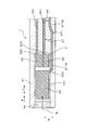
- FIG. 2 is a schematic cross-sectional view of the gas sensor taken along the line II-II in FIG. 1.
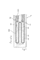
- FIG. 3 is a schematic cross-sectional view of the gas sensor as viewed in the direction of arrows III-III in FIG. 1.
- FIG. 4 is a schematic cross-sectional view of the gas sensor as viewed in the direction of arrows IV-IV in FIG. 1.
- the typical sectional view showing the whole gas sensor composition concerning an embodiment.
- the graph which shows the relationship between the space
- the gas sensor 1 includes a solid electrolyte plate 2, a gas chamber to be measured 101, a pump electrode 21, a monitor electrode 22, a sensor electrode 23, a reference electrode 24, a heater 5, and a pump cell unit. 31, a monitor cell unit 32 and a sensor cell unit 33.
- the solid electrolyte plate 2 has oxygen ion conductivity and is formed in a plate shape.
- the gas chamber 101 to be measured is formed adjacent to the first surface 201 of the solid electrolyte plate 2.
- the pump electrode 21 is provided on the first surface 201 of the solid electrolyte plate 2 and is exposed to the measured gas G in the measured gas chamber 101.
- the monitor electrode 22 and the sensor electrode 23 are provided adjacent to each other on the first surface 201 of the solid electrolyte plate 2 at a position downstream of the pump electrode 21 with respect to the flow of the gas G to be measured. It is exposed to the measurement gas G in the gas chamber 101.
- the reference electrode 24 is provided on the second surface 202 of the solid electrolyte plate 2 on the opposite side of the first surface 201 and is exposed to the reference gas A.
- the heater 5 is disposed opposite to the second surface 202 of the solid electrolyte plate 2 and heats the solid electrolyte plate 2.
- the pump cell unit 31 adjusts the oxygen concentration of the measured gas G in the measured gas chamber 101 when a voltage is applied between the pump electrode 21 and the reference electrode 24 via the first portion 2A of the solid electrolyte plate 2. To do.
- the monitor cell unit 32 detects the current flowing between the monitor electrode 22 and the reference electrode 24 through the second portion 2B of the solid electrolyte plate 2 and the gas to be measured after the oxygen concentration is adjusted by the pump electrode 21 The residual oxygen concentration in G is detected.
- the sensor cell unit 33 detects a current flowing between the sensor electrode 23 and the reference electrode 24 via the third portion 2C of the solid electrolyte plate 2, and the gas to be measured after the oxygen concentration is adjusted by the pump electrode 21 The concentration of a specific gas component other than oxygen in G is detected.
- the pump electrode extending from the pump electrode 21 toward the downstream side of the flow of the measurement gas G in the width direction W orthogonal to the flow direction F of the measurement gas G in the measurement gas chamber 101.
- a monitor electrode 22 is disposed between the lead portion 211 and the sensor electrode 23. Between the pump electrode lead portion 211 and the sensor electrode lead portion 231 extending from the sensor electrode 23 toward the downstream side of the flow of the measurement gas G, the downstream side of the flow of the measurement gas G from the monitor electrode 22 A monitor electrode lead portion 221 extending toward is disposed.
- a gap w1 of 0.5 mm or more is provided between the upstream electrode portion 211A including the portion facing the monitor electrode 22 from the width direction W in the pump electrode lead portion 211 and the monitor electrode lead portion 221.
- the gas sensor 1 is used by being disposed in an exhaust passage of an internal combustion engine in a vehicle, and detects the concentration of NOx (nitrogen oxide) as a specific gas component contained in the exhaust gas using the exhaust gas flowing through the exhaust passage as the gas to be measured G. To do.
- the gas sensor 1 constitutes a sensor element and is formed in a long shape. A proximal end portion in the longitudinal direction L of the gas sensor 1 is held by an insulator 12, and the insulator 12 is held by a housing 13 attached to the internal combustion engine.
- a detection unit 11 into which the gas G to be measured flows is provided at the distal end portion in the longitudinal direction L of the gas sensor 1, and the detection unit 11 is covered by a protective cover 14 provided with a through hole 141. ing.
- the gas chamber 101 to be measured, the pump electrode 21, the monitor electrode 22, the sensor electrode 23, the reference electrode 24, the heater 5, the pump cell unit 31, the monitor cell unit 32, and the sensor cell unit 33 are provided in the detection unit 11.
- the distal end side in the longitudinal direction L of the gas sensor 1 corresponds to the upstream side with respect to the flow of the measured gas G in the measured gas chamber 101
- the proximal end side in the longitudinal direction L of the gas sensor 1 is This corresponds to the downstream side of the flow of the measurement gas G in the measurement gas chamber 101.
- the solid electrolyte plate 2 is made of yttria-stabilized zirconia, and only one is disposed in the gas sensor 1.
- a second insulating plate 42 is laminated on the first surface 201 of the solid electrolyte plate 2 with a notched first insulating plate 41 for forming the gas chamber 101 to be measured.
- the first insulating plate 41 and the second insulating plate 42 are made of an insulator such as alumina.
- the first insulating plate 41 is provided on the base end side portion in the longitudinal direction L and the both side portions in the width direction W on the first surface 201 of the solid electrolyte plate 2.
- An opening is formed in the distal end portion of the first insulating plate 41 in the longitudinal direction L, and a diffusion resistor 44 made of a porous body is disposed in the opening.
- the measured gas chamber 101 is formed between the first surface 201 of the solid electrolyte plate 2 and the second insulating plate 42 so as to be surrounded by the diffusion resistor 44 and the first insulating plate 41.
- the measured gas G flows into the measured gas chamber 101 via the diffusion resistor 44.
- the pump electrode 21, the monitor electrode 22, the sensor electrode 23, and the reference electrode 24 are provided on the same solid electrolyte plate 2.
- the pump electrode 21 is positioned upstream of the flow of the gas G to be measured in the gas chamber 101 to be measured and is closer to the diffusion resistor 44 than the monitor electrode 22 and the sensor electrode 23.
- the monitor electrode 22 and the sensor electrode 23 are formed to have the same size and are disposed at the same distance from the pump electrode 21.
- the arrangement conditions of the monitor electrode 22 and the sensor electrode 23 are made equal to the flow of the measurement gas G after passing through the arrangement position of the pump electrode 21 in the measurement gas chamber 101.
- One reference electrode 24 is provided at a position facing the pump electrode 21, the monitor electrode 22, and the sensor electrode 23 as a whole. In addition, three reference electrodes 24 can be separately provided at positions facing the pump electrode 21, the monitor electrode 22, and the sensor electrode 23.
- the pump electrode 21 and the monitor electrode 22 are made of a cermet material containing a metal component such as a Pt—Au alloy that can decompose oxygen and not decompose a specific gas component.
- the sensor electrode 23 is made of oxygen and a specific gas.
- a cermet material containing a metal component such as a Pt—Rh alloy capable of decomposing the component is used.
- the reference electrode 24 is configured using a cermet material containing a metal component such as Pt capable of decomposing oxygen.
- the heater 5 includes two ceramic substrates 51 such as alumina, and a conductor layer 52 embedded between the two ceramic substrates 51.
- the heater 5 is laminated on the second surface 202 of the solid electrolyte plate 2 via a third insulating plate 43 for forming a reference gas chamber 102 into which the atmosphere as the reference gas A is introduced.
- the third insulating plate 43 is made of an insulator such as alumina.
- the third insulating plate 43 is formed in a notch shape having an opening at the base end in the longitudinal direction L of the gas sensor 1.
- the reference gas chamber 102 is formed between the second surface 202 of the solid electrolyte plate 2 and the ceramic substrate 51 so as to be surrounded on three sides by the third insulating plate 43.
- the reference gas A flows into the reference gas chamber 102 from the proximal end portion in the longitudinal direction L of the gas sensor 1.
- the conductor layer 52 of the heater 5 connects the pair of lead parts 521 connected to the energization means outside the gas sensor 1 and the pair of lead parts 521, and is applied to the pair of lead parts 521.
- a heat generating portion 522 that generates heat when energized by voltage.
- the heat generating portion 522 mainly generates heat due to Joule heat.
- the pump electrode 21, the monitor electrode 22, and the sensor electrode 23 are heated to a desired operating temperature by the heat generated by the heat generating unit 522.
- the resistance value of the heat generating part 522 is larger than the resistance value of the lead part 521.
- the resistance value of the heat generating portion 522 can occupy 50% or more of the resistance value of the entire conductor layer 52.
- the heat generating portion 522 is provided at a position facing substantially the entire planar area where the pump electrode 21, the monitor electrode 22, and the sensor electrode 23 are disposed.
- the resistance value of the heat generating part 522 can be made larger than the resistance value of the lead part 521 by making the pattern wiring of the heat generating part 522 thinner than the pattern wiring of the lead part 521. Further, the heat generation portion 522 can also generate heat by making the film thickness of the heat generation portion 522 smaller than the film thickness of the lead portion 521 or by making the material of the heat generation portion 522 larger in specific resistance than the material of the lead portion 521. The resistance value of the part 522 can be made larger than the resistance value of the lead part 521. In addition, the resistance value of the heat generating part 522 can be made larger than the resistance value of the lead part 521 by combining techniques for changing the thickness, film thickness, constituent material, and the like of the pattern wiring.
- the pump cell unit 31 includes a pump electrode 21, a part of the reference electrode 24, and a first part 2 ⁇ / b> A of the solid electrolyte plate 2 sandwiched between the pump electrode 21 and a part of the reference electrode 24. And is composed of.
- a voltage application circuit 61 for applying a voltage between the electrodes 21 and 24 is provided.
- oxygen in the gas G to be measured that contacts the pump electrode 21 is decomposed and passed through the solid electrolyte plate 2. Oxygen ions permeate the reference electrode 24, and oxygen in the measurement gas G in the measurement gas chamber 101 is reduced.
- the monitor cell unit 32 includes a monitor electrode 22, a part of the reference electrode 24, and a second part of the solid electrolyte plate 2 sandwiched between the monitor electrode 22 and a part of the reference electrode 24. 2B.
- a first current detection circuit for detecting a current flowing between the electrodes 22 and 24 between the monitor electrode 22 and the reference electrode 24 in a state where a predetermined voltage is applied between the electrodes 22 and 24. 62 is provided. When residual oxygen in the measurement gas G that contacts the monitor electrode 22 is decomposed, oxygen ions permeate the reference electrode 24 through the solid electrolyte plate 2. At this time, the current flowing between the monitor electrode 22 and the reference electrode 24 via the second portion 2B of the solid electrolyte plate 2 is detected by the first current detection circuit 62.
- the sensor cell part 33 includes a sensor electrode 23, a part of the reference electrode 24, and a third part of the solid electrolyte plate 2 sandwiched between the sensor electrode 23 and a part of the reference electrode 24. 2C.
- a second current detection circuit that detects a current flowing between the electrodes 23 and 24 in a state where a predetermined voltage is applied between the electrodes 23 and 24. 63 is provided.
- oxygen ions permeate the reference electrode 24 through the solid electrolyte plate 2.
- the current flowing between the sensor electrode 23 and the reference electrode 24 via the third portion 2C of the solid electrolyte plate 2 is detected by the second current detection circuit 63.
- movement of the gas sensor 1 the influence of the residual oxygen in the waste gas which is the to-be-measured gas G is relieve
- the concentration of NOx that is the specific gas component is obtained.
- the pump electrode lead portion 211 is formed on the first surface 201 of the solid electrolyte plate 2 so as to be connected to the pump electrode 21.
- the pump electrode lead portion 211 is for connecting the pump electrode 21 to the voltage application circuit 61.
- the pump electrode lead 211 is displaced from the downstream end of one side surface in the width direction W of the pump electrode 21 to one side in the width direction W, and the flow of the gas G to be measured in the gas chamber 101 to be measured. Is provided toward the downstream side (the base end side in the longitudinal direction L of the gas sensor 1).
- the entire pump electrode lead portion 211 excluding the portion 212 connected to the pump electrode 21 is embedded between the solid electrolyte plate 2 and the first insulating plate 41.
- the entire downstream portion 211B located on the downstream side with respect to the flow of the gas G is embedded between the solid electrolyte plate 2 and the first insulating plate 41.
- the pump electrode lead portion 211 can be enclosed by the solid electrolyte plate 2 and the first insulating plate 41.
- the monitor electrode lead portion 221 extending from the monitor electrode 22 toward the downstream side of the flow of the gas G to be measured is connected to the downstream end portion of the monitor electrode 22.
- the monitor electrode lead 221 is for connecting the monitor electrode 22 to the first current detection circuit 62.
- the monitor electrode lead part 221 is linearly provided toward the downstream side of the flow of the gas G to be measured.
- the whole of the monitor electrode lead part 221 except the portion 222 connected to the monitor electrode 22 is embedded between the solid electrolyte plate 2 and the first insulating plate 41.
- a sensor electrode lead portion 231 extending from the sensor electrode 23 toward the downstream side of the flow of the gas G to be measured is connected to the downstream end portion of the sensor electrode 23.
- the sensor electrode lead portion 231 is for connecting the sensor electrode 23 to the second current detection circuit 63.
- the sensor electrode lead portion 231 is linearly provided toward the downstream side with respect to the flow of the gas G to be measured.
- the entire sensor electrode lead portion 231 except the portion 232 connected to the sensor electrode 23 is buried between the solid electrolyte plate 2 and the first insulating plate 41.
- the monitor electrode lead portion 221 is disposed between the pump electrode lead portion 211 and the sensor electrode lead portion 231 in the width direction W of the gas sensor 1.
- the monitor electrode lead portion 221 is connected to the monitor electrode 22 while being biased to the side away from the pump electrode lead portion 211. More specifically, the monitor electrode lead portion 221 is connected to a position farthest from the pump electrode lead portion 211 at the downstream end portion of the monitor electrode 22. With this configuration, the monitor electrode lead portion 221 can be easily moved away from the pump electrode lead portion 211.
- the sensor electrode lead portion 231 is connected to the sensor electrode 23 while being biased to the side away from the pump electrode lead portion 211.
- the sensor electrode lead portion 231 is connected to a position farthest from the pump electrode lead portion 211 at the downstream end portion of the sensor electrode 23. With this configuration, it becomes easy to move the sensor electrode lead portion 231 away from the pump electrode lead portion 211.
- the interval w1 between the upstream portion 211A of the pump electrode lead portion 211 and the monitor electrode lead portion 221 is the interval between the downstream portion 211B of the pump electrode lead portion 211 and the monitor electrode lead portion 221. Greater than w2.
- the upstream portion 211A of the pump electrode lead portion 211 is arranged around the one side in the width direction W so as to be away from the monitor electrode 22, and the downstream portion 211B of the pump electrode lead portion 211 is disposed upstream. It is arranged closer to the monitor electrode lead portion 221 than the portion 211A.
- an interval w1 of 0.5 mm or more is provided between the upstream portion 211A of the pump electrode lead portion 211 and the monitor electrode lead portion 221. This interval w1 can be set to 1.5 mm or less in consideration of the size of the gas sensor 1 actually manufactured.
- the pump electrode 21, the monitor electrode 22, and the sensor electrode 23 are heated to 650 ° C. or more by the heat generating part 522 of the heater 5.
- the center of heating by the heat generating part 522 of the heater 5 is set at a position facing the pump electrode 21.
- the upstream portion 211 ⁇ / b> A of the pump electrode lead portion 211 is heated to 650 ° C. or more by the heat generating portion 522 of the heater 5.
- the front end portion of the gas sensor 1 is in a high temperature region of 650 ° C. or higher, and is easily affected by electrical noise generated from the pump electrode lead portion 211 when a current is passed through the pump electrode 21 due to the high temperature. .
- the pump electrode lead portion 211 can be separated from the monitor electrode 22 and the sensor electrode 23 as much as possible by diverting the upstream portion 211A of the pump electrode lead portion 211 from the monitor electrode 22 to one side in the width direction W. Further, when the arrangement position of the pump electrode lead portion 211 is too close to the outer end face in the width direction W between the solid electrolyte plate 2 and the first insulating plate 41, the solid electrolyte plate 2 and the first insulating plate 41 are arranged. It becomes easy to produce the trouble at the time of joining. In this case, the measurement gas G leaks easily from the measurement gas chamber 101 to the outside of the gas sensor 1. Therefore, the downstream portion 211 ⁇ / b> B of the pump electrode lead portion 211 is disposed at a position close to the monitor electrode lead portion 221.
- the pump electrode lead part 211, the monitor electrode lead part 221 and the sensor electrode lead part 231 are made of a cermet material containing a metal component such as Pt.
- Each lead portion is provided up to the base end portion in the longitudinal direction L of the gas sensor 1 and is electrically connected to a control device outside the gas sensor 1 via a metal fitting, a lead wire, and the like.
- the monitor electrode 22 and the monitor electrode lead part 221 are arranged between the pump electrode lead part 211 and the sensor electrode 23 and the sensor electrode lead part 231 in the width direction W of the gas sensor 1.
- the specific gas component such as NOx detected by the sensor cell unit 33 is only slightly present in the measured gas G such as exhaust gas, and the current flowing through the sensor cell unit 33 when the specific gas component is decomposed at the sensor electrode 23 is It is weak.
- the current flowing through the pump cell unit 31 flows when the oxygen contained in the measurement gas G is reduced, and is significantly larger than the current flowing through the sensor cell unit 33.
- the sensor electrode 23 for detecting a weak current is moved away from the pump electrode lead part 211 through which a large current flows, so that the sensor cell part 33 causes a leakage current or the like generated when a current flows through the pump electrode lead part 211. It can be made less susceptible to the effects of electrical noise.
- the monitor electrode 22 is interposed between the pump electrode lead portion 211 and the sensor electrode 23. Thereby, the monitor electrode 22 plays a role of guarding the sensor electrode 23, and the influence of electrical noise generated from the pump electrode lead portion 211 on the sensor electrode 23 can be reduced.
- the monitor cell unit 32 is used for correcting the detection of the concentration of the specific gas component by reducing the influence of the residual oxygen concentration, and directly detects the concentration of the specific gas component. It is not a thing. Therefore, the sensor electrode 23 is affected by the electrical noise generated from the pump electrode lead portion 211, and the monitor electrode 22 is electrically generated from the pump electrode lead portion 211 as compared with the error generated in the detection of the concentration of the specific gas component. The error that occurs in the detection of the concentration of a specific gas component due to the influence of noise is small.
- the following effects can be obtained by interposing the monitor electrode 22 between the pump electrode lead portion 211 and the sensor electrode 23 in the width direction W of the gas sensor 1.
- the gas sensor 1 when the laminated body in which the solid electrolyte plate 2, the insulating plates 41, 42, 43, the heater 5, etc. are laminated, or when the gas sensor 1 is used, a high temperature environment is used. There is a possibility that the metal components and the like of the pump electrode lead part 211 exposed to the vaporization may volatilize.
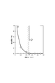
- FIG. 6 an error in the concentration of nitric oxide detected by the gas sensor 1 with respect to the actual concentration of nitric oxide is shown as a detection error.
- the detection error increases as the interval w1 between the upstream portion 211A of the pump electrode lead portion 211 and the monitor electrode lead portion 221 decreases.
- the detection error increases rapidly.
- the interval w1 between the lead portions 211A and 221 is smaller than 0.5 mm, the electrical insulation between the upstream portion 211A of the pump electrode lead portion 211 and the monitor electrode lead portion 221 decreases. This is considered to be because the leakage current generated between these lead portions 211A and 221 is increased.
- the arrangement relationship between the pump electrode lead portion 211, the sensor electrode 23, and the monitor electrode 22 is made appropriate, and the distance between the upstream portion 211A of the pump electrode lead portion 211 and the monitor electrode 22 is increased. It is important to make w1 appropriate.
- the present invention is not limited to the above-described embodiments, and can be implemented in various forms without departing from the scope of the invention.
Abstract
ガスセンサ1は、ポンプ電極21を用いて被測定ガスGの酸素濃度を調整するポンプセル部と、モニタ電極22を用いて被測定ガスGの残留酸素濃度を検出するモニタセル部と、センサ電極23を用いて被測定ガスGにおける特定ガス成分の濃度を検出するセンサセル部と、を備える。ポンプ電極リード部211と、センサ電極23との間には、モニタ電極22が配置されている。ポンプ電極リード部211の上流側部分211Aと、モニタ電極リード部221との間には、0.5mm以上の間隔w1が設けられている。
Description
本発明は、排ガス等の被測定ガスにおける特定ガス成分の濃度を測定するガスセンサに関する。
ガスセンサは、内燃機関から排出される排ガスにおける酸素濃度や酸素以外の特定ガス成分(例えば、NOx)の濃度等を測定するために用いられる。例えば、特許文献1には、排ガスにおける酸素以外の特定ガス成分の濃度を測定するガスセンサが開示されている。
特許文献1に開示されたガスセンサは、固体電解質体における、被測定ガス室に接する表面には、排ガス(即ち、被測定ガス)の酸素濃度を調整するポンプ電極と、酸素濃度が調整された後の排ガスにおける残留酸素濃度を監視するモニタ電極と、酸素濃度が調整された後の排ガスにおける特定ガス成分の濃度を検出するセンサ電極と、を配置して構成されている。また、モニタ電極とセンサ電極とは、被測定ガス室における被測定ガスの流れについてのポンプ電極の下流側に互いに隣接して配置されている。
特許文献1に開示されたガスセンサは、固体電解質体における、被測定ガス室に接する表面には、排ガス(即ち、被測定ガス)の酸素濃度を調整するポンプ電極と、酸素濃度が調整された後の排ガスにおける残留酸素濃度を監視するモニタ電極と、酸素濃度が調整された後の排ガスにおける特定ガス成分の濃度を検出するセンサ電極と、を配置して構成されている。また、モニタ電極とセンサ電極とは、被測定ガス室における被測定ガスの流れについてのポンプ電極の下流側に互いに隣接して配置されている。
しかしながら、ポンプ電極においては、排ガスの酸素濃度を少なくするために、大きな電流を流しており、ポンプ電極に流れる電流値は、モニタ電極及びセンサ電極に流れる電流値と比べて桁違いに大きい。特許文献1に開示されたガスセンサにおいては、ポンプ電極に通電を行うためのポンプ電極リード部は、センサ電極の側方に隣接して配置されている。そのため、特定ガス成分の濃度に応じてセンサ電極に流れる電流が、ポンプ電極に流れる電流の漏洩等に基づく電気的ノイズの影響を受けて変動するおそれがある。そのため、特定ガス成分の濃度の検出精度を高めるためには更なる工夫が必要とされる。
本発明は、かかる課題に鑑みてなされたものであり、被測定ガスにおける特定ガス成分の濃度の検出精度を高めることができるガスセンサを提供することを目的としている。
本発明の一実施形態に係るガスセンサは、
酸素イオン伝導性を有する固体電解質板と、
該固体電解質板の第1表面に隣接して形成された被測定ガス室と、
上記被測定ガス室における被測定ガスに晒されるよう、上記固体電解質板の上記第1表面に設けられたポンプ電極と、
上記被測定ガス室における被測定ガスに晒されるよう、上記固体電解質板の上記第1表面における、被測定ガスの流れについての上記ポンプ電極の下流側の位置に、互いに隣接して設けられたモニタ電極及びセンサ電極と、
基準ガスに晒されるよう、上記第1表面の反対側にある、上記固体電解質板の第2表面に設けられた少なくとも1つの基準電極と、
上記固体電解質板の上記第2表面に対向して配置され、該固体電解質板を加熱するヒータと、
上記ポンプ電極と上記基準電極との間に上記固体電解質板の第一部分を介して電圧が印加されるときに、上記被測定ガス室における被測定ガスの酸素濃度を調整するポンプセル部と、
上記モニタ電極と上記基準電極との間に上記固体電解質板の第二部分を介して流れる電流を検出して、上記ポンプ電極によって酸素濃度が調整された後の被測定ガスにおける残留酸素濃度を検出するモニタセル部と、
上記センサ電極と上記基準電極との間に上記固体電解質板の第三部分を介して流れる電流を検出して、上記ポンプ電極によって酸素濃度が調整された後の被測定ガスにおける特定ガス成分の濃度を検出するセンサセル部と、を備え、
被測定ガスの流れの方向に直交する幅方向において、上記ポンプ電極から被測定ガスの流れについての下流側に向けて伸びるポンプ電極リード部と、上記センサ電極との間には、上記モニタ電極が配置されており、
上記ポンプ電極リード部と、上記センサ電極から被測定ガスの流れについての下流側に向けて伸びるセンサ電極リード部との間には、上記モニタ電極から被測定ガスの流れについての下流側に向けて伸びるモニタ電極リード部が配置されており、
上記ポンプ電極リード部における、上記幅方向から上記モニタ電極に対向する部分を含む上流側部分と、上記モニタ電極リード部との間には、0.5mm以上の間隔が設けられている。
上記ガスセンサにおいては、ポンプ電極リード部とセンサ電極との配置関係に工夫をしている。具体的には、被測定ガスの流れの方向に直交する幅方向において、ポンプ電極リード部とセンサ電極との間にモニタ電極が配置されている。また、ポンプ電極リード部とセンサ電極リード部との間には、モニタ電極リード部が配置されている。
センサセル部によって検出する特定ガス成分は、被測定ガス中に僅かしか存在せず、この特定ガス成分がセンサ電極において分解される際にセンサセル部に流れる電流は微弱である。一方、ポンプセル部に流れる電流は、排ガス等の被測定ガスに含まれる酸素を減らす際に流れるものであり、センサセル部に流れる電流に比べて桁違いに大きい。
センサセル部によって検出する特定ガス成分は、被測定ガス中に僅かしか存在せず、この特定ガス成分がセンサ電極において分解される際にセンサセル部に流れる電流は微弱である。一方、ポンプセル部に流れる電流は、排ガス等の被測定ガスに含まれる酸素を減らす際に流れるものであり、センサセル部に流れる電流に比べて桁違いに大きい。
そのため、微弱な電流を検出するセンサ電極を、大電流が流れるポンプ電極リード部から遠ざけることにより、センサセル部が、ポンプ電極リード部に電流を流す際に生じる電気的ノイズの影響を受けにくくすることができる。特に、上記ガスセンサにおいては、ポンプ電極リード部とセンサ電極との間にモニタ電極を介在させている。これにより、モニタ電極がセンサ電極をガードする役割を果たし、ポンプ電極リード部から生じる電気的ノイズがセンサ電極に与える影響を少なくすることができる。
センサセル部においては、ポンプ電極によって酸素濃度が調整された後の被測定ガスにおける特定ガス成分の濃度だけでなく、残留酸素濃度も検出される。そして、ガスセンサにおいては、センサセル部の出力からモニタセル部の出力を差し引くことにより、酸素濃度が調整された後の被測定ガスにおける残留酸素濃度が特定ガス成分の濃度に与える影響を緩和することができる。
このように、モニタセル部は、残留酸素濃度による影響を緩和して特定ガス成分の濃度の検出の補正を行うために用いられるものであり、特定ガス成分の濃度の検出を直接行うものではない。そのため、センサ電極が、ポンプ電極リード部から生じる電気的ノイズの影響を受けて、特定ガス成分の濃度の検出に生じる誤差に比べて、モニタ電極が、ポンプ電極リード部から生じる電気的ノイズの影響を受けて、特定ガス成分の濃度の検出に生じる誤差は小さい。
特に、ポンプ電極リード部の上流側部分と、モニタ電極リード部との間に、0.5mm以上の間隔を設けることにより、特定ガス成分の濃度の検出に生じる誤差をより小さくすることができる。
それ故、上記ガスセンサにおいては、ポンプ電極リード部とセンサ電極との間にモニタ電極を介在させることによって、特定ガス成分の濃度の検出精度を高めることができる。
それ故、上記ガスセンサにおいては、ポンプ電極リード部とセンサ電極との間にモニタ電極を介在させることによって、特定ガス成分の濃度の検出精度を高めることができる。
本形態に係るガスセンサ1は、図1~図3に示すように、固体電解質板2、被測定ガス室101、ポンプ電極21、モニタ電極22、センサ電極23、基準電極24、ヒータ5、ポンプセル部31、モニタセル部32及びセンサセル部33を備える。
固体電解質板2は、酸素イオン伝導性を有しており、板状に形成されている。被測定ガス室101は、固体電解質板2の第1表面201に隣接して形成されている。ポンプ電極21は、固体電解質板2の第1表面201に設けられており、被測定ガス室101における被測定ガスGに晒されている。モニタ電極22とセンサ電極23とは、固体電解質板2の第1表面201における、被測定ガスGの流れについてのポンプ電極21の下流側の位置に、互いに隣接して設けられており、被測定ガス室101における被測定ガスGに晒されている。基準電極24は、第1表面201の反対側にある、固体電解質板2の第2表面202に設けられており、基準ガスAに晒されている。
固体電解質板2は、酸素イオン伝導性を有しており、板状に形成されている。被測定ガス室101は、固体電解質板2の第1表面201に隣接して形成されている。ポンプ電極21は、固体電解質板2の第1表面201に設けられており、被測定ガス室101における被測定ガスGに晒されている。モニタ電極22とセンサ電極23とは、固体電解質板2の第1表面201における、被測定ガスGの流れについてのポンプ電極21の下流側の位置に、互いに隣接して設けられており、被測定ガス室101における被測定ガスGに晒されている。基準電極24は、第1表面201の反対側にある、固体電解質板2の第2表面202に設けられており、基準ガスAに晒されている。
ヒータ5は、固体電解質板2の第2表面202に対向して配置されており、固体電解質板2を加熱するものである。ポンプセル部31は、ポンプ電極21と基準電極24との間に固体電解質板2の第一部分2Aを介して電圧が印加されるときに、被測定ガス室101における被測定ガスGの酸素濃度を調整するものである。モニタセル部32は、モニタ電極22と基準電極24との間に固体電解質板2の第二部分2Bを介して流れる電流を検出して、ポンプ電極21によって酸素濃度が調整された後の被測定ガスGにおける残留酸素濃度を検出するものである。センサセル部33は、センサ電極23と基準電極24との間に固体電解質板2の第三部分2Cを介して流れる電流を検出して、ポンプ電極21によって酸素濃度が調整された後の被測定ガスGにおける酸素以外の特定ガス成分の濃度を検出するものである。
図3に示すように、被測定ガス室101における被測定ガスGの流れの方向Fに直交する幅方向Wにおいて、ポンプ電極21から被測定ガスGの流れについての下流側に向けて伸びるポンプ電極リード部211と、センサ電極23との間には、モニタ電極22が配置されている。ポンプ電極リード部211と、センサ電極23から被測定ガスGの流れについての下流側に向けて伸びるセンサ電極リード部231との間には、モニタ電極22から被測定ガスGの流れについての下流側に向けて伸びるモニタ電極リード部221が配置されている。ポンプ電極リード部211における、幅方向Wからモニタ電極22に対向する部分を含む上流側部分211Aと、モニタ電極リード部221との間には、0.5mm以上の間隔w1が設けられている。
以下に、本形態に係るガスセンサ1の構成について、詳細に説明する。
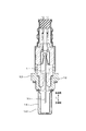
ガスセンサ1は、車両における内燃機関の排気通路に配置されて用いられ、排気通路を流れる排ガスを被測定ガスGとして、排ガス中に含まれる特定ガス成分としてのNOx(窒素酸化物)の濃度を検出するものである。図5に示すように、ガスセンサ1は、センサ素子を構成するものであり、長尺形状に形成されている。ガスセンサ1の長尺方向Lの基端側部分は、絶縁碍子12に保持されており、絶縁碍子12は、内燃機関に取り付けられるハウジング13に保持されている。また、ガスセンサ1の長尺方向Lの先端側部分には、被測定ガスGが流入する検知部11が設けられており、検知部11は、貫通孔141が設けられた保護カバー14によって覆われている。被測定ガス室101、ポンプ電極21、モニタ電極22、センサ電極23、基準電極24、ヒータ5、ポンプセル部31、モニタセル部32及びセンサセル部33等は、検知部11に設けられている。
ガスセンサ1は、車両における内燃機関の排気通路に配置されて用いられ、排気通路を流れる排ガスを被測定ガスGとして、排ガス中に含まれる特定ガス成分としてのNOx(窒素酸化物)の濃度を検出するものである。図5に示すように、ガスセンサ1は、センサ素子を構成するものであり、長尺形状に形成されている。ガスセンサ1の長尺方向Lの基端側部分は、絶縁碍子12に保持されており、絶縁碍子12は、内燃機関に取り付けられるハウジング13に保持されている。また、ガスセンサ1の長尺方向Lの先端側部分には、被測定ガスGが流入する検知部11が設けられており、検知部11は、貫通孔141が設けられた保護カバー14によって覆われている。被測定ガス室101、ポンプ電極21、モニタ電極22、センサ電極23、基準電極24、ヒータ5、ポンプセル部31、モニタセル部32及びセンサセル部33等は、検知部11に設けられている。
本形態において、ガスセンサ1の長尺方向Lの先端側は、被測定ガス室101における被測定ガスGの流れについての上流側に相当し、ガスセンサ1の長尺方向Lの基端側は、被測定ガス室101における被測定ガスGの流れについての下流側に相当する。
図1、図2に示すように、固体電解質板2は、イットリア安定化ジルコニアによって構成されており、ガスセンサ1において1枚だけ配置されている。固体電解質板2の第1表面201には、被測定ガス室101を形成するための切欠き形状の第1絶縁板41を介して第2絶縁板42が積層されている。第1絶縁板41及び第2絶縁板42は、アルミナ等の絶縁物によって構成されている。第1絶縁板41は、固体電解質板2の第1表面201における、長尺方向Lの基端側部分及び幅方向Wの両側部分に設けられている。第1絶縁板41の長尺方向Lの先端側部分には、開口部が形成されており、この開口部には、多孔質体からなる拡散抵抗体44が配置されている。被測定ガス室101は、固体電解質板2の第1表面201と第2絶縁板42との間において、拡散抵抗体44と第1絶縁板41とによって四方が囲まれて形成されている。被測定ガスGは、拡散抵抗体44を経由して被測定ガス室101に流入する。
図1、図3に示すように、ポンプ電極21、モニタ電極22、センサ電極23及び基準電極24は、同じ固体電解質板2に設けられている。ポンプ電極21は、被測定ガス室101における、被測定ガスGの流れについての上流側の位置であって、モニタ電極22及びセンサ電極23に比べて拡散抵抗体44に近い位置に配置されている。モニタ電極22とセンサ電極23とは、同等の大きさに形成されており、ポンプ電極21から同等の距離に配置されている。そして、被測定ガス室101における、ポンプ電極21の配置位置を通過した後の被測定ガスGの流れに対して、モニタ電極22とセンサ電極23との配置条件を同等にしている。
基準電極24は、ポンプ電極21、モニタ電極22及びセンサ電極23の全体に対向する位置に1つ設けられている。これ以外にも、基準電極24は、ポンプ電極21、モニタ電極22及びセンサ電極23のそれぞれに対向する位置に別々に3つ設けることもできる。
ポンプ電極21及びモニタ電極22は、酸素を分解可能で特定ガス成分を分解しない、Pt-Au合金等の金属成分を含むサーメット材料を用いて構成されており、センサ電極23は、酸素及び特定ガス成分を分解可能な、Pt-Rh合金等の金属成分を含むサーメット材料を用いて構成されている。基準電極24は、酸素を分解可能な、Pt等の金属成分を含むサーメット材料を用いて構成されている。
ポンプ電極21及びモニタ電極22は、酸素を分解可能で特定ガス成分を分解しない、Pt-Au合金等の金属成分を含むサーメット材料を用いて構成されており、センサ電極23は、酸素及び特定ガス成分を分解可能な、Pt-Rh合金等の金属成分を含むサーメット材料を用いて構成されている。基準電極24は、酸素を分解可能な、Pt等の金属成分を含むサーメット材料を用いて構成されている。
図1、図2、図4に示すように、ヒータ5は、アルミナ等の2枚のセラミック基板51と、2枚のセラミック基板51の間に埋設された導体層52とを有している。ヒータ5は、基準ガスAとしての大気が導入される基準ガス室102を形成するための第3絶縁板43を介して、固体電解質板2の第2表面202に積層されている。第3絶縁板43は、アルミナ等の絶縁物によって構成されている。
第3絶縁板43は、ガスセンサ1の長尺方向Lの基端部に開口部を有する切欠き形状に形成されている。基準ガス室102は、固体電解質板2の第2表面202とセラミック基板51との間において、第3絶縁板43によって三方が囲まれて形成されている。基準ガスAは、ガスセンサ1の長尺方向Lの基端部から基準ガス室102に流入する。
第3絶縁板43は、ガスセンサ1の長尺方向Lの基端部に開口部を有する切欠き形状に形成されている。基準ガス室102は、固体電解質板2の第2表面202とセラミック基板51との間において、第3絶縁板43によって三方が囲まれて形成されている。基準ガスAは、ガスセンサ1の長尺方向Lの基端部から基準ガス室102に流入する。
図4に示すように、ヒータ5の導体層52は、ガスセンサ1の外部における通電手段に接続される一対のリード部521と、一対のリード部521を繋ぎ、一対のリード部521に印加される電圧によって通電されるときに発熱する発熱部522とを有している。導体層52に通電が行われるときには、ジュール熱によって主に発熱部522が発熱する。そして、この発熱部522の発熱によって、ポンプ電極21、モニタ電極22及びセンサ電極23が所望の作動温度に昇温される。
発熱部522の抵抗値は、リード部521の抵抗値よりも大きい。発熱部522の抵抗値は、導体層52全体の抵抗値の50%以上を占めるようにすることができる。発熱部522は、ポンプ電極21、モニタ電極22及びセンサ電極23が配置された平面領域の略全体に対向する位置に設けられている。
発熱部522の抵抗値は、リード部521の抵抗値よりも大きい。発熱部522の抵抗値は、導体層52全体の抵抗値の50%以上を占めるようにすることができる。発熱部522は、ポンプ電極21、モニタ電極22及びセンサ電極23が配置された平面領域の略全体に対向する位置に設けられている。
発熱部522のパターン配線を、リード部521のパターン配線よりも細くすることによって、発熱部522の抵抗値をリード部521の抵抗値よりも大きくすることができる。また、発熱部522の膜厚をリード部521の膜厚よりも小さくすること、または発熱部522の構成材料をリード部521の構成材料よりも比抵抗の大きな材料とすること等によっても、発熱部522の抵抗値をリード部521の抵抗値よりも大きくすることができる。また、パターン配線の太さ、膜厚、構成材料等を変化させる手法を組み合わせて、発熱部522の抵抗値をリード部521の抵抗値よりも大きくすることもできる。
図1に示すように、ポンプセル部31は、ポンプ電極21と、基準電極24の一部と、ポンプ電極21と基準電極24の一部との間に挟まれた固体電解質板2の第一部分2Aとによって構成されている。ポンプ電極21と基準電極24との間には、これらの電極21,24の間に電圧を印加する電圧印加回路61が設けられている。電圧印加回路61によって、ポンプ電極21と基準電極24との間に電圧が印加されるときに、ポンプ電極21に接触する被測定ガスG中の酸素が分解されて、固体電解質板2を介して基準電極24へ酸素イオンが透過し、被測定ガス室101における被測定ガスG中の酸素が減らされる。
図2に示すように、モニタセル部32は、モニタ電極22と、基準電極24の一部と、モニタ電極22と基準電極24の一部との間に挟まれた固体電解質板2の第二部分2Bとによって構成されている。モニタ電極22と基準電極24との間には、これらの電極22,24の間に所定の電圧を印加した状態で、これらの電極22,24の間に流れる電流を検出する第一電流検出回路62が設けられている。モニタ電極22に接触する被測定ガスG中の残留酸素が分解されるときには、固体電解質板2を介して基準電極24へ酸素イオンが透過する。このとき、モニタ電極22と基準電極24との間に固体電解質板2の第二部分2Bを介して流れる電流が、第一電流検出回路62によって検出される。
同図に示すように、センサセル部33は、センサ電極23と、基準電極24の一部と、センサ電極23と基準電極24の一部との間に挟まれた固体電解質板2の第三部分2Cとによって構成されている。センサ電極23と基準電極24との間には、これらの電極23,24の間に所定の電圧を印加した状態で、これらの電極23,24の間に流れる電流を検出する第二電流検出回路63が設けられている。センサ電極23に接触する被測定ガスG中の残留酸素及び特定ガス成分が分解されるときには、固体電解質板2を介して基準電極24へ酸素イオンが透過する。このとき、センサ電極23と基準電極24との間に固体電解質板2の第三部分2Cを介して流れる電流が、第二電流検出回路63によって検出される。
また、ガスセンサ1の動作を制御する制御部においては、センサセル部33の電流の出力からモニタセル部32の電流の出力が差し引かれることにより、被測定ガスGである排ガス中の残留酸素の影響が緩和されて、特定ガス成分であるNOxの濃度が求められる。
また、ガスセンサ1の動作を制御する制御部においては、センサセル部33の電流の出力からモニタセル部32の電流の出力が差し引かれることにより、被測定ガスGである排ガス中の残留酸素の影響が緩和されて、特定ガス成分であるNOxの濃度が求められる。
図3に示すように、ポンプ電極リード部211は、固体電解質板2の第1表面201において、ポンプ電極21に繋がって形成されている。ポンプ電極リード部211は、ポンプ電極21を電圧印加回路61に接続するためのものである。ポンプ電極リード部211は、ポンプ電極21の幅方向Wにおける一方側の側面の下流側端部から、幅方向Wにおける一方側に位置ずれして、被測定ガス室101における被測定ガスGの流れについての下流側(ガスセンサ1の長尺方向Lの基端側)に向けて設けられている。ポンプ電極リード部211における、ポンプ電極21に繋がる部分212を除く全体は、固体電解質板2と第1絶縁板41との間に埋設されている。
より具体的には、ポンプ電極リード部211における、ポンプ電極21に繋がる部分212を除く、幅方向Wからモニタ電極22に対向する部分を含む上流側部分211Aと、上流側部分211Aよりも被測定ガスGの流れについての下流側に位置する下流側部分211Bの全体とは、固体電解質板2と第1絶縁板41との間に埋設されている。この構成により、ポンプ電極リード部211を固体電解質板2と第1絶縁板41とによって包み込むことができる。これにより、ガスセンサ1を製造する際に、固体電解質板2、各絶縁板41,42,43及びヒータ5等を積層した積層体の燒結を行うとき、あるいはガスセンサ1を使用するときにおいて、高温の環境下に晒されたポンプ電極リード部211の金属成分等が揮発して、センサ電極23やモニタ電極22に付着することを抑制することができる。
固体電解質板2の第1表面201において、モニタ電極22の下流側端部には、モニタ電極22から被測定ガスGの流れについての下流側に向けて伸びるモニタ電極リード部221が繋がっている。モニタ電極リード部221は、モニタ電極22を第一電流検出回路62に接続するためのものである。モニタ電極リード部221は、被測定ガスGの流れについての下流側に向けて直線状に設けられている。モニタ電極リード部221における、モニタ電極22に繋がる部分222を除く全体は、固体電解質板2と第1絶縁板41との間に埋設されている。
固体電解質板2の第1表面201において、センサ電極23の下流側端部には、センサ電極23から被測定ガスGの流れについての下流側に向けて伸びるセンサ電極リード部231が繋がっている。センサ電極リード部231は、センサ電極23を第二電流検出回路63に接続するためのものである。センサ電極リード部231は、被測定ガスGの流れについての下流側に向けて直線状に設けられている。センサ電極リード部231における、センサ電極23に繋がる部分232を除く全体は、固体電解質板2と第1絶縁板41との間に埋設されている。
図3に示すように、モニタ電極リード部221は、ガスセンサ1の幅方向Wにおいて、ポンプ電極リード部211とセンサ電極リード部231との間に配置されている。
モニタ電極リード部221は、ポンプ電極リード部211から離れた側に偏ってモニタ電極22に繋がっている。より具体的には、モニタ電極リード部221は、モニタ電極22の下流側端部における、ポンプ電極リード部211から最も離れた位置に繋がっている。この構成により、モニタ電極リード部221をポンプ電極リード部211から遠ざけることが容易になる。また、センサ電極リード部231は、ポンプ電極リード部211から離れた側に偏ってセンサ電極23に繋がっている。より具体的には、センサ電極リード部231は、センサ電極23の下流側端部における、ポンプ電極リード部211から最も離れた位置に繋がっている。この構成により、センサ電極リード部231をポンプ電極リード部211から遠ざけることが容易になる。
モニタ電極リード部221は、ポンプ電極リード部211から離れた側に偏ってモニタ電極22に繋がっている。より具体的には、モニタ電極リード部221は、モニタ電極22の下流側端部における、ポンプ電極リード部211から最も離れた位置に繋がっている。この構成により、モニタ電極リード部221をポンプ電極リード部211から遠ざけることが容易になる。また、センサ電極リード部231は、ポンプ電極リード部211から離れた側に偏ってセンサ電極23に繋がっている。より具体的には、センサ電極リード部231は、センサ電極23の下流側端部における、ポンプ電極リード部211から最も離れた位置に繋がっている。この構成により、センサ電極リード部231をポンプ電極リード部211から遠ざけることが容易になる。
同図に示すように、ポンプ電極リード部211の上流側部分211Aと、モニタ電極リード部221との間隔w1は、ポンプ電極リード部211の下流側部分211Bと、モニタ電極リード部221との間隔w2よりも大きい。そして、ポンプ電極リード部211の上流側部分211Aは、モニタ電極22から離れるように幅方向Wの一方側に迂回して配置されており、ポンプ電極リード部211の下流側部分211Bは、上流側部分211Aに比べてモニタ電極リード部221に近づいて配置されている。また、ポンプ電極リード部211の上流側部分211Aと、モニタ電極リード部221との間には、0.5mm以上の間隔w1が設けられている。この間隔w1は、実際に製造するガスセンサ1の大きさを考慮して、1.5mm以下とすることができる。
ポンプ電極21、モニタ電極22及びセンサ電極23は、ヒータ5の発熱部522によって650℃以上に加熱される。ヒータ5の発熱部522による加熱中心は、ポンプ電極21と対向する位置に設定されている。また、ポンプ電極リード部211の上流側部分211Aも同様に、ヒータ5の発熱部522によって650℃以上に加熱される。そして、ガスセンサ1の先端側部分は、650℃以上の高温領域となり、高温であることによって、ポンプ電極21に電流を流す際に、ポンプ電極リード部211から生じる電気的ノイズの影響を受けやすくなる。
ポンプ電極リード部211の上流側部分211Aを、モニタ電極22から幅方向Wの一方側に迂回させることにより、ポンプ電極リード部211をモニタ電極22及びセンサ電極23から極力離すことができる。また、ポンプ電極リード部211の配置位置が、固体電解質板2と第1絶縁板41との間における幅方向Wの外側の端面に近づき過ぎる場合には、固体電解質板2と第1絶縁板41とを接合する際の不具合が生じやすくなる。また、この場合には、被測定ガス室101からガスセンサ1の外部への被測定ガスGのリークが生じやすくなる。そのため、ポンプ電極リード部211の下流側部分211Bは、モニタ電極リード部221に近くなる位置に配置している。
ポンプ電極リード部211、モニタ電極リード部221及びセンサ電極リード部231は、Pt等の金属成分を含むサーメット材料によって構成されている。各リード部は、ガスセンサ1の長尺方向Lの基端部まで設けられ、金具、リード線等を介してガスセンサ1の外部における制御機器に電気的に接続される。
本形態のガスセンサ1においては、ガスセンサ1の幅方向Wにおいて、ポンプ電極リード部211と、センサ電極23及びセンサ電極リード部231との間に、モニタ電極22及びモニタ電極リード部221を配置している。
センサセル部33によって検出するNOx等の特定ガス成分は、排ガス等の被測定ガスG中に僅かしか存在せず、この特定ガス成分がセンサ電極23において分解される際にセンサセル部33に流れる電流は微弱である。一方、ポンプセル部31に流れる電流は、被測定ガスGに含まれる酸素を減らす際に流れるものであり、センサセル部33に流れる電流に比べて桁違いに大きい。
センサセル部33によって検出するNOx等の特定ガス成分は、排ガス等の被測定ガスG中に僅かしか存在せず、この特定ガス成分がセンサ電極23において分解される際にセンサセル部33に流れる電流は微弱である。一方、ポンプセル部31に流れる電流は、被測定ガスGに含まれる酸素を減らす際に流れるものであり、センサセル部33に流れる電流に比べて桁違いに大きい。
そのため、微弱な電流を検出するためのセンサ電極23を、大電流が流れるポンプ電極リード部211から遠ざけることにより、センサセル部33が、ポンプ電極リード部211に電流を流す際に生じるリーク電流等の電気的ノイズの影響を受けにくくすることができる。ガスセンサ1においては、ポンプ電極リード部211とセンサ電極23との間にモニタ電極22を介在させている。これにより、モニタ電極22がセンサ電極23をガードする役割を果たし、ポンプ電極リード部211から生じる電気的ノイズがセンサ電極23に与える影響を少なくすることができる。
また、上述したように、モニタセル部32は、残留酸素濃度による影響を緩和して特定ガス成分の濃度の検出の補正を行うために用いられるものであり、特定ガス成分の濃度の検出を直接行うものではない。そのため、センサ電極23が、ポンプ電極リード部211から生じる電気的ノイズの影響を受けて、特定ガス成分の濃度の検出に生じる誤差に比べて、モニタ電極22が、ポンプ電極リード部211から生じる電気的ノイズの影響を受けて、特定ガス成分の濃度の検出に生じる誤差は小さい。特に、ポンプ電極リード部211の上流側部分211Aと、モニタ電極リード部221との間に、0.5mm以上の間隔を設けることにより、特定ガス成分の濃度の検出に生じる誤差をより小さくすることができる。
それ故、ガスセンサ1においては、ポンプ電極リード部211とセンサ電極23との間にモニタ電極22を介在させることによって、特定ガス成分の濃度の検出精度を高めることができる。
それ故、ガスセンサ1においては、ポンプ電極リード部211とセンサ電極23との間にモニタ電極22を介在させることによって、特定ガス成分の濃度の検出精度を高めることができる。
また、ガスセンサ1の幅方向Wにおいて、ポンプ電極リード部211とセンサ電極23との間にモニタ電極22を介在させることによって、次の効果を得ることもできる。
ガスセンサ1を製造する際に、固体電解質板2、各絶縁板41,42,43及びヒータ5等を積層した積層体の燒結を行うとき、あるいはガスセンサ1を使用するときにおいては、高温の環境下に晒されたポンプ電極リード部211の金属成分等が揮発するおそれがある。この場合、ポンプ電極リード部211から揮発した金属成分等がセンサ電極23に付着して、センサ電極23が被毒すると、特定ガス成分の濃度の検出精度を悪化させる要因となり得る。そのため、ポンプ電極リード部211とセンサ電極23との間にモニタ電極22を介在させ、センサ電極23をポンプ電極リード部211からできるだけ遠ざけることによって、センサ電極23の被毒のおそれを少なくすることができる。
ガスセンサ1を製造する際に、固体電解質板2、各絶縁板41,42,43及びヒータ5等を積層した積層体の燒結を行うとき、あるいはガスセンサ1を使用するときにおいては、高温の環境下に晒されたポンプ電極リード部211の金属成分等が揮発するおそれがある。この場合、ポンプ電極リード部211から揮発した金属成分等がセンサ電極23に付着して、センサ電極23が被毒すると、特定ガス成分の濃度の検出精度を悪化させる要因となり得る。そのため、ポンプ電極リード部211とセンサ電極23との間にモニタ電極22を介在させ、センサ電極23をポンプ電極リード部211からできるだけ遠ざけることによって、センサ電極23の被毒のおそれを少なくすることができる。
(確認試験)
本確認試験においては、ポンプ電極リード部211の上流側部分211Aとモニタ電極リード部221との間に設けられた間隔w1と、ガスセンサ1による特定ガス成分の濃度の検出誤差との関係を測定した。そして、このリード部211A,221同士の間の間隔w1が異なる複数のガスセンサ1を試作し、各ガスセンサ1の被測定ガス室101には、酸素の濃度が5%、一酸化窒素(NO)の濃度が100ppm、残部が窒素である被測定ガスGを流入させて、特定ガス成分の濃度の検出を行った。
本確認試験においては、ポンプ電極リード部211の上流側部分211Aとモニタ電極リード部221との間に設けられた間隔w1と、ガスセンサ1による特定ガス成分の濃度の検出誤差との関係を測定した。そして、このリード部211A,221同士の間の間隔w1が異なる複数のガスセンサ1を試作し、各ガスセンサ1の被測定ガス室101には、酸素の濃度が5%、一酸化窒素(NO)の濃度が100ppm、残部が窒素である被測定ガスGを流入させて、特定ガス成分の濃度の検出を行った。
図6においては、実際の一酸化窒素の濃度に対する、ガスセンサ1によって検出した一酸化窒素の濃度の誤差を検出誤差として示す。同図に示すように、ポンプ電極リード部211の上流側部分211Aとモニタ電極リード部221との間の間隔w1が狭くなるほど検出誤差が大きくなる。特に、リード部211A,221同士の間の間隔w1が0.5mmよりも小さくなると、検出誤差が急激に増加することが分かる。この理由は、リード部211A,221同士の間の間隔w1が0.5mmよりも小さくなると、ポンプ電極リード部211の上流側部分211Aとモニタ電極リード部221との間の電気的絶縁性が低下して、これらのリード部211A,221間に生じるリーク電流が増大したためであると考える。
特定ガス成分の濃度に起因する微小な電流を検出する本形態のガスセンサ1においては、電気的ノイズが特定ガス成分の濃度の検出に与える影響が無視できない。そのため、上述したように、ポンプ電極リード部211と、センサ電極23及びモニタ電極22との配置関係を適切にし、かつ、ポンプ電極リード部211の上流側部分211Aとモニタ電極22との間の間隔w1を適切にすることが重要となる。
本発明は、上述した実施形態に限定されるものではなく、その要旨を逸脱しない範囲において様々な形態で実施することができる。
本発明は、上述した実施形態に限定されるものではなく、その要旨を逸脱しない範囲において様々な形態で実施することができる。
1 ガスセンサ
101 被測定ガス室
2 固体電解質板
21 ポンプ電極
211 ポンプ電極リード部
22 モニタ電極
23 センサ電極
24 基準電極
5 ヒータ
101 被測定ガス室
2 固体電解質板
21 ポンプ電極
211 ポンプ電極リード部
22 モニタ電極
23 センサ電極
24 基準電極
5 ヒータ
Claims (4)
- 酸素イオン伝導性を有する固体電解質板(2)と、
該固体電解質板の第1表面(201)に隣接して形成された被測定ガス室(101)と、
上記被測定ガス室における被測定ガス(G)に晒されるよう、上記固体電解質板の上記第1表面に設けられたポンプ電極(21)と、
上記被測定ガス室における被測定ガスに晒されるよう、上記固体電解質板の上記第1表面における、被測定ガスの流れについての上記ポンプ電極の下流側の位置に、互いに隣接して設けられたモニタ電極(22)及びセンサ電極(23)と、
基準ガス(A)に晒されるよう、上記第1表面の反対側にある、上記固体電解質板の第2表面(202)に設けられた少なくとも1つの基準電極(24)と、
上記固体電解質板の上記第2表面に対向して配置され、該固体電解質板を加熱するヒータ(5)と、
上記ポンプ電極と上記基準電極との間に上記固体電解質板の第一部分(2A)を介して電圧が印加されるときに、上記被測定ガス室における被測定ガスの酸素濃度を調整するポンプセル部(31)と、
上記モニタ電極と上記基準電極との間に上記固体電解質板の第二部分(2B)を介して流れる電流を検出して、上記ポンプ電極によって酸素濃度が調整された後の被測定ガスにおける残留酸素濃度を検出するモニタセル部(32)と、
上記センサ電極と上記基準電極との間に上記固体電解質板の第三部分(2C)を介して流れる電流を検出して、上記ポンプ電極によって酸素濃度が調整された後の被測定ガスにおける特定ガス成分の濃度を検出するセンサセル部(33)と、を備え、
被測定ガスの流れの方向(F)に直交する幅方向(W)において、上記ポンプ電極から被測定ガスの流れについての下流側に向けて伸びるポンプ電極リード部(211)と、上記センサ電極との間には、上記モニタ電極が配置されており、
上記ポンプ電極リード部と、上記センサ電極から被測定ガスの流れについての下流側に向けて伸びるセンサ電極リード部(231)との間には、上記モニタ電極から被測定ガスの流れについての下流側に向けて伸びるモニタ電極リード部(221)が配置されており、
上記ポンプ電極リード部における、上記幅方向から上記モニタ電極に対向する部分を含む上流側部分(211A)と、上記モニタ電極リード部との間には、0.5mm以上の間隔(w1)が設けられている、ガスセンサ(1)。 - 上記モニタ電極リード部は、上記ポンプ電極リード部から離れた側に偏って上記モニタ電極に繋がっており、
上記センサ電極リード部は、上記ポンプ電極リード部から離れた側に偏って上記センサ電極に繋がっている、請求項1に記載のガスセンサ。 - 上記ポンプ電極リード部の上記上流側部分は、上記固体電解質板と、上記被測定ガス室を形成する絶縁板(41)との間に埋設されている、請求項1又は2に記載のガスセンサ。
- 上記ポンプ電極リード部の上記上流側部分と上記モニタ電極リード部との間に設けられた上記間隔は、上記ポンプ電極リード部における、上記上流側部分よりも被測定ガスの流れについての下流側に位置する下流側部分(211B)と上記モニタ電極リード部との間に設けられた間隔(w2)よりも大きい、請求項1~3のいずれか一項に記載のガスセンサ。
Priority Applications (2)
| Application Number | Priority Date | Filing Date | Title |
|---|---|---|---|
| US16/061,790 US10890552B2 (en) | 2015-12-17 | 2016-12-07 | Gas sensor |
| DE112016005780.6T DE112016005780T5 (de) | 2015-12-17 | 2016-12-07 | Gassensor |
Applications Claiming Priority (2)
| Application Number | Priority Date | Filing Date | Title |
|---|---|---|---|
| JP2015246458A JP6382178B2 (ja) | 2015-12-17 | 2015-12-17 | ガスセンサ |
| JP2015-246458 | 2015-12-17 |
Publications (1)
| Publication Number | Publication Date |
|---|---|
| WO2017104499A1 true WO2017104499A1 (ja) | 2017-06-22 |
Family
ID=59056464
Family Applications (1)
| Application Number | Title | Priority Date | Filing Date |
|---|---|---|---|
| PCT/JP2016/086326 WO2017104499A1 (ja) | 2015-12-17 | 2016-12-07 | ガスセンサ |
Country Status (4)
| Country | Link |
|---|---|
| US (1) | US10890552B2 (ja) |
| JP (1) | JP6382178B2 (ja) |
| DE (1) | DE112016005780T5 (ja) |
| WO (1) | WO2017104499A1 (ja) |
Families Citing this family (1)
| Publication number | Priority date | Publication date | Assignee | Title |
|---|---|---|---|---|
| JP7234988B2 (ja) * | 2020-03-31 | 2023-03-08 | 株式会社デンソー | ガスセンサ |
Citations (7)
| Publication number | Priority date | Publication date | Assignee | Title |
|---|---|---|---|---|
| US20060185978A1 (en) * | 2005-02-08 | 2006-08-24 | Ngk Spark Plug Co., Ltd. | Gas sensor and method for manufacturing the same |
| JP2013051070A (ja) * | 2011-08-30 | 2013-03-14 | Denso Corp | セラミックヒータ及びそれを用いたガスセンサ素子 |
| JP2013257215A (ja) * | 2012-06-13 | 2013-12-26 | Ngk Spark Plug Co Ltd | センサ素子 |
| JP2015062013A (ja) * | 2013-08-21 | 2015-04-02 | 株式会社デンソー | ガスセンサ |
| JP2015064341A (ja) * | 2013-08-30 | 2015-04-09 | 株式会社デンソー | ガス濃度検出装置 |
| JP2015064227A (ja) * | 2013-09-24 | 2015-04-09 | 株式会社デンソー | ガス濃度検出装置 |
| JP2015215334A (ja) * | 2014-04-22 | 2015-12-03 | 株式会社デンソー | NOx濃度測定システム |
Family Cites Families (1)
| Publication number | Priority date | Publication date | Assignee | Title |
|---|---|---|---|---|
| JP3973900B2 (ja) | 2001-02-08 | 2007-09-12 | 株式会社日本自動車部品総合研究所 | ガスセンサ素子 |
-
2015
- 2015-12-17 JP JP2015246458A patent/JP6382178B2/ja active Active
-
2016
- 2016-12-07 WO PCT/JP2016/086326 patent/WO2017104499A1/ja active Application Filing
- 2016-12-07 DE DE112016005780.6T patent/DE112016005780T5/de active Pending
- 2016-12-07 US US16/061,790 patent/US10890552B2/en active Active
Patent Citations (7)
| Publication number | Priority date | Publication date | Assignee | Title |
|---|---|---|---|---|
| US20060185978A1 (en) * | 2005-02-08 | 2006-08-24 | Ngk Spark Plug Co., Ltd. | Gas sensor and method for manufacturing the same |
| JP2013051070A (ja) * | 2011-08-30 | 2013-03-14 | Denso Corp | セラミックヒータ及びそれを用いたガスセンサ素子 |
| JP2013257215A (ja) * | 2012-06-13 | 2013-12-26 | Ngk Spark Plug Co Ltd | センサ素子 |
| JP2015062013A (ja) * | 2013-08-21 | 2015-04-02 | 株式会社デンソー | ガスセンサ |
| JP2015064341A (ja) * | 2013-08-30 | 2015-04-09 | 株式会社デンソー | ガス濃度検出装置 |
| JP2015064227A (ja) * | 2013-09-24 | 2015-04-09 | 株式会社デンソー | ガス濃度検出装置 |
| JP2015215334A (ja) * | 2014-04-22 | 2015-12-03 | 株式会社デンソー | NOx濃度測定システム |
Also Published As
| Publication number | Publication date |
|---|---|
| JP2017111039A (ja) | 2017-06-22 |
| JP6382178B2 (ja) | 2018-08-29 |
| DE112016005780T5 (de) | 2018-10-11 |
| US20180364193A1 (en) | 2018-12-20 |
| US10890552B2 (en) | 2021-01-12 |
Similar Documents
| Publication | Publication Date | Title |
|---|---|---|
| JP6393722B2 (ja) | ガスセンサ | |
| US10921283B2 (en) | Gas sensor for detecting concentration of specific gas component | |
| JP6561719B2 (ja) | ガスセンサ | |
| JP6321968B2 (ja) | ガスセンサ素子 | |
| JP4680276B2 (ja) | ガスセンサ素子 | |
| JP6596535B2 (ja) | ガスセンサ | |
| JP5254154B2 (ja) | ガスセンサ | |
| US10837938B2 (en) | Gas sensor element and gas sensor unit | |
| JP6350359B2 (ja) | ガスセンサ | |
| JP3922239B2 (ja) | ガス濃度検出装置 | |
| WO2017104499A1 (ja) | ガスセンサ | |
| JP2015230220A (ja) | ガスセンサ素子 | |
| US10895553B2 (en) | Gas sensor | |
| WO2020195080A1 (ja) | ガスセンサ | |
| JP2004151017A (ja) | 積層型ガスセンサ素子 | |
| JP6511405B2 (ja) | ガスセンサ | |
| JP2004093307A (ja) | ガスセンサ素子 | |
| WO2016067975A1 (ja) | ガスセンサ | |
| JP2008134258A (ja) | ガスセンサ素子 | |
| JP2021032812A (ja) | センサ素子 |
Legal Events
| Date | Code | Title | Description |
|---|---|---|---|
| 121 | Ep: the epo has been informed by wipo that ep was designated in this application |
Ref document number: 16875479 Country of ref document: EP Kind code of ref document: A1 |
|
| WWE | Wipo information: entry into national phase |
Ref document number: 112016005780 Country of ref document: DE |
|
| 122 | Ep: pct application non-entry in european phase |
Ref document number: 16875479 Country of ref document: EP Kind code of ref document: A1 |