WO2017104435A1 - 方向指示機構、および方向指示機構の組立方法 - Google Patents
方向指示機構、および方向指示機構の組立方法 Download PDFInfo
- Publication number
- WO2017104435A1 WO2017104435A1 PCT/JP2016/085802 JP2016085802W WO2017104435A1 WO 2017104435 A1 WO2017104435 A1 WO 2017104435A1 JP 2016085802 W JP2016085802 W JP 2016085802W WO 2017104435 A1 WO2017104435 A1 WO 2017104435A1
- Authority
- WO
- WIPO (PCT)
- Prior art keywords
- case
- moderation
- fastening member
- bracket
- indicating mechanism
- Prior art date
- Legal status (The legal status is an assumption and is not a legal conclusion. Google has not performed a legal analysis and makes no representation as to the accuracy of the status listed.)
- Ceased
Links
Images







Classifications
-
- B—PERFORMING OPERATIONS; TRANSPORTING
- B60—VEHICLES IN GENERAL
- B60Q—ARRANGEMENT OF SIGNALLING OR LIGHTING DEVICES, THE MOUNTING OR SUPPORTING THEREOF OR CIRCUITS THEREFOR, FOR VEHICLES IN GENERAL
- B60Q1/00—Arrangement of optical signalling or lighting devices, the mounting or supporting thereof or circuits therefor
- B60Q1/26—Arrangement of optical signalling or lighting devices, the mounting or supporting thereof or circuits therefor the devices being primarily intended to indicate the vehicle, or parts thereof, or to give signals, to other traffic
- B60Q1/34—Arrangement of optical signalling or lighting devices, the mounting or supporting thereof or circuits therefor the devices being primarily intended to indicate the vehicle, or parts thereof, or to give signals, to other traffic for indicating change of drive direction
-
- B—PERFORMING OPERATIONS; TRANSPORTING
- B60—VEHICLES IN GENERAL
- B60R—VEHICLES, VEHICLE FITTINGS, OR VEHICLE PARTS, NOT OTHERWISE PROVIDED FOR
- B60R16/00—Electric or fluid circuits specially adapted for vehicles and not otherwise provided for; Arrangement of elements of electric or fluid circuits specially adapted for vehicles and not otherwise provided for
- B60R16/02—Electric or fluid circuits specially adapted for vehicles and not otherwise provided for; Arrangement of elements of electric or fluid circuits specially adapted for vehicles and not otherwise provided for electric constitutive elements
-
- G—PHYSICS
- G05—CONTROLLING; REGULATING
- G05G—CONTROL DEVICES OR SYSTEMS INSOFAR AS CHARACTERISED BY MECHANICAL FEATURES ONLY
- G05G1/00—Controlling members, e.g. knobs or handles; Assemblies or arrangements thereof; Indicating position of controlling members
- G05G1/04—Controlling members for hand actuation by pivoting movement, e.g. levers
-
- G—PHYSICS
- G05—CONTROLLING; REGULATING
- G05G—CONTROL DEVICES OR SYSTEMS INSOFAR AS CHARACTERISED BY MECHANICAL FEATURES ONLY
- G05G25/00—Other details or appurtenances of control mechanisms, e.g. supporting intermediate members elastically
-
- H—ELECTRICITY
- H01—ELECTRIC ELEMENTS
- H01H—ELECTRIC SWITCHES; RELAYS; SELECTORS; EMERGENCY PROTECTIVE DEVICES
- H01H25/00—Switches with compound movement of handle or other operating part
- H01H25/04—Operating part movable angularly in more than one plane, e.g. joystick
Definitions
- the present disclosure relates to a direction indicating mechanism mounted on a vehicle and an assembling method of the direction indicating mechanism.
- Patent Document 1 discloses a turn signal switch which is an example of this type of direction indicating mechanism. Various components constituting the turn signal switch are accommodated in a space defined by a switch case and a cover.
- a first aspect for achieving the above object is a direction indicating mechanism mounted on a vehicle, A rotating member that is rotatable in response to an operation of the lever; A moderation piece connected to the rotating member; A first case and a second case defining a space for accommodating the rotating member and the moderation piece; A fastening member fastening the first case and the second case; With The fastening member has a moderation surface with which the moderation piece comes into contact.
- a second aspect for achieving the above object is a method for assembling a direction indicating mechanism mounted on a vehicle,
- the first case and the second case are arranged in a first direction so as to define a space for accommodating a rotation member that can be rotated in accordance with an operation of the lever and a moderation piece connected to the rotation member.
- a fastening member having a moderation surface with which the moderation piece comes into contact with the first case and the second case in a second direction intersecting the first direction the first case and The second case is fastened.
- the fastening of both is completed only by the operation of coupling the fastening member to the first case and the second case.
- the fastening member has a moderation surface, which is essential for the direction indicating mechanism, in a part thereof. Therefore, as compared with a manufacturing method that requires screw tightening, not only an increase in the number of parts and an increase in the size of the housing due to screw holes can be suppressed, but also the assembly workability can be improved. As a result, an increase in the size of the casing of the direction indication mechanism and an increase in manufacturing cost can be suppressed.
- the above direction indicating mechanism can be configured as follows.
- the first case and the second case are arranged in a first direction
- the fastening member includes a first convex portion and a second convex portion extending in a second direction intersecting the first direction
- the first convex portion and the second convex portion are arranged in the first direction
- a part of the first case and a part of the second case are sandwiched between the first convex part and the second convex part.
- the first case and the second case can be fastened more firmly than a configuration in which a plurality of cases constituting the housing are fastened by snap fit or the like.
- the fastening member itself can have a moderation surface positioning function. By determining the position of the moderation surface with high accuracy, the operation position of the rotating member is determined with high accuracy via the moderation piece. Therefore, it is possible not only to suppress an increase in size and manufacturing cost of the casing of the direction indicating mechanism, but also to suppress the shakiness of components constituting the casing and improve the operability of the rotating member.
- the direction indicating mechanism described above can be configured as follows.
- the first convex portion and the second convex portion have a portion that becomes narrower as the distance between the first convex portion and the second convex portion in the first direction is away from the moderation surface. .
- the above direction indicating mechanism can be configured as follows.
- the fastening member includes an engaging portion engaged with at least one of the first case and the second case so as to restrict displacement in a direction away from the moderation piece.
- the fastening member when the moderation piece is pressed against the moderation surface by the urging force of the elastic member, the fastening member is prevented from being displaced in a direction away from the moderation piece. Thereby, it can prevent that the fastening state by a fastening member cannot be maintained with the repeated use of a direction indication mechanism. Therefore, rattling of parts constituting the casing of the direction indicating mechanism can be further suppressed.
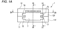
- FIG. 1A shows the appearance of the direction indicating mechanism 1 according to an embodiment.
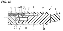
- FIG. 1B is a sectional view of a part of the direction indicating mechanism 1 as viewed from the direction of the arrow along the line IB-IB in FIG. 1A.
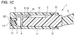
- FIG. 1C is a cross-sectional view of a part of the direction indicating mechanism 1 as viewed from the direction of the arrow along the line IC-IC in FIG. 1A.
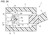
- 2A is a cross-sectional view of a part of the direction indicating mechanism 1 as viewed from the direction of the arrow along the line IIA-IIA in FIG. 1A.
- the expressions “clockwise” and “counterclockwise” used in the following description are based on the direction in FIG. 2A.
- the direction indicating mechanism 1 is mounted on a vehicle. Specifically, it is arranged on the side of the steering shaft connected to the steering wheel that controls the steering of the vehicle.
- the direction indicating mechanism 1 includes a lever 2.
- the lever 2 is operated by the driver in order to turn on and off the direction indicator lamp indicating the steering direction of the vehicle.
- the direction indicating mechanism 1 includes a bracket 3 (an example of a rotating member).
- the bracket 3 includes a pair of rotating shafts 31.
- the bracket 3 is connected to the lever 2.
- the bracket 3 rotates clockwise and counterclockwise about the pair of rotating shafts 31 in response to the operation of the lever 2.
- the direction indicating mechanism 1 includes a moderation piece 4 and a coil spring 5 (an example of an elastic member).
- the moderation piece 4 is connected to the bracket 3 so as to be displaceable. Specifically, as shown in FIG. 1B, a part of the moderation piece 4 and the coil spring 5 are disposed in the sliding hole 32 formed in the bracket 3. The moderation piece 4 is slidable in the sliding hole 32 of the bracket 3 in accordance with the elastic deformation of the coil spring 5.
- the direction indicating mechanism 1 includes a moderation surface 6.
- the moderation surface 6 and the coil spring 5 urge the moderation piece 4 toward the moderation surface 6. Thereby, the moderation piece 4 can contact the moderation surface 6.
- the direction indicating mechanism 1 includes a first case 11 and a second case 12.
- the first case 11 and the second case 12 form a casing of the direction indicating mechanism 1.
- the first case 11 and the second case 12 define a space for accommodating the bracket 3, the moderation piece 4, the coil spring 5, and the moderation surface 6.
- the direction indicating mechanism 1 includes a ratchet 8.
- the ratchet 8 includes a first rotation shaft 81.
- the bracket 3 has a ratchet contact surface 33.
- the first rotation shaft 81 of the ratchet 8 is held by the bracket 3 and the second case 12 so as to contact the ratchet contact surface 33.
- the ratchet 8 includes a second rotation shaft 82.
- a groove 12 a is formed in the second case 12.
- the second rotating shaft 82 of the ratchet 8 is held by the second case 12 so as to be slidable in the groove 12a.
- the first rotation shaft 81 of the ratchet 8 is biased toward the ratchet contact surface 33 of the bracket 3 by an elastic member (not shown) such as a coil spring or a leaf spring.
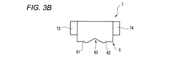
- the moderation surface 6 includes a first peak portion 61, a second peak portion 62, and a neutral holding portion 63.
- the 1st peak part 61 and the 2nd peak part 62 are connected so that a trough part may be formed.
- a neutral holding portion 63 is defined by the valley.
- the ratchet contact surface 33 of the bracket 3 includes a first contact surface 33a and a second contact surface 33b.
- the first contact surface 33a and the second contact surface 33b are connected so as to form a ridge 33c.
- the ratchet 8 includes an engaging protrusion 83.
- the first rotation shaft 81 of the ratchet 8 is disposed at the peak portion 33c of the ratchet contact surface.
- the engaging protrusion 83 is retracted from the turning locus of a cancel cam (not shown) mounted on the steering shaft of the vehicle.
- FIG. 2B shows this state.
- the moderation piece 4 moves so as to get over the first peak portion 61 adjacent to the neutral holding portion 63.
- the moderation piece 4 slides in the sliding hole 32 of the bracket 3 so as to compress the coil spring 5.
- the moderation piece 4 is prevented from returning to the neutral holding portion 63 by the urging force of the first peak portion 61 and the coil spring 5. Therefore, the bracket 3 is held at the left turn instruction position.
- a signal for turning on the left turn direction indicator of the vehicle is output from the direction indication mechanism 1 through a switch mechanism (not shown).
- the first rotation shaft 81 of the ratchet 8 moves along the first contact surface 33a from the peak portion 33c of the ratchet contact surface 33.
- the ratchet 8 advances toward the steering shaft by the urging force of the elastic member.
- the rotation of the bracket 3 is regulated by the inner wall of the first case 11 (or a regulating member such as a protrusion provided on the inner wall).
- the engaging protrusion 83 of the ratchet 8 enters the rotation locus of the cancel cam.
- the left turn instruction operation is cancelled.
- the cancel cam mounted on the steering shaft rotates clockwise and engages with the engagement protrusion 83 of the ratchet 8 entering the rotation locus.
- the ratchet 8 is rotatable about the first rotation shaft 81 and the second rotation shaft 82 in a plane parallel to the rotation locus. Accordingly, the ratchet 8 rotates counterclockwise about the first rotation shaft 81 and the second rotation shaft 82 so as to allow passage of the cancel cam that rotates counterclockwise.
- Rotational force of the cancel cam transmitted through the ratchet 8 rotates the bracket 3 clockwise through a cancel mechanism (not shown).
- the moderation piece 4 moves over the first peak 61 of the moderation surface 6 and moves to the neutral holding unit 63. Thereby, the output of the signal for turning on the left turn direction indicator of the vehicle is stopped.
- the lever 2 When turning right or changing to the right lane, the lever 2 is operated so that the bracket 3 rotates clockwise around the rotation shaft 31. As the bracket 3 rotates, the moderation piece 4 moves so as to get over the second peak portion 62 adjacent to the neutral holding portion 63. At this time, the moderation piece 4 slides in the sliding hole 32 of the bracket 3 so as to compress the coil spring 5.
- the moderation piece 4 is prevented from returning to the neutral holding portion 63 by the urging force of the second peak portion 62 and the coil spring 5. Therefore, the bracket 3 is held at the left turn instruction position.
- a signal for turning on the right turn direction indicator of the vehicle is output from the direction indication mechanism 1 through a switch mechanism (not shown).
- the first rotation shaft 81 of the ratchet 8 moves along the second contact surface 33b from the peak portion 33c of the ratchet contact surface 33.
- the ratchet 8 advances toward the steering shaft by the urging force of the elastic member.
- the rotation of the bracket 3 is regulated by the inner wall of the first case 11 (or a regulating member such as a protrusion provided on the inner wall).
- the engaging protrusion 83 of the ratchet 8 enters the rotation locus of the cancel cam.
- the right turn instruction operation is cancelled.
- the cancel cam mounted on the steering shaft rotates counterclockwise and engages with the engagement protrusion 83 of the ratchet 8 entering the rotation locus.
- the ratchet 8 rotates clockwise about the first rotation shaft 81 and the second rotation shaft 82 so as to allow passage of the cancel cam that rotates counterclockwise.
- Rotational force of the cancel cam transmitted via the ratchet 8 rotates the bracket 3 counterclockwise via a cancel mechanism (not shown).
- the moderation piece 4 moves over the second peak 62 of the moderation surface 6 and moves to the neutral holding portion 63. Thereby, the output of the signal for turning on the right turn direction indicator of the vehicle is stopped.
- the direction indicating mechanism 1 includes a fastening member 7.
- the fastening member 7 fastens the first case 11 and the second case 12.
- the fastening member 7 has the moderation surface 6 described above.
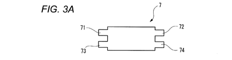
- FIG. 3A is a rear view showing the appearance of the fastening member 7.
- FIG. 3B is a top view showing the appearance of the fastening member 7.
- FIG. 3C is a front view showing the appearance of the fastening member 7.
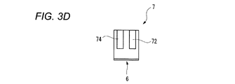
- FIG. 3D is a right side view showing the appearance of the fastening member 7. Since the bottom view and the left side view are symmetrical with the top view and the right side view, respectively, illustration is omitted.
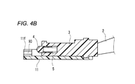
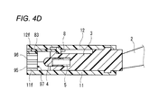
- 4A to 4D show an assembly method of the direction indicating mechanism 1.
- 4A and 4C are front views corresponding to FIG. 1A.
- 4B and 4D are cross-sectional views corresponding to FIG. 1B.
- the lever 2 is connected, and the bracket 3 in a state where the moderation piece 4 and the coil spring 5 are mounted is coupled to the first case 11.
- the second case 12 is coupled to the first case 11 from above so that the ratchet 8 is sandwiched between the bracket 3 and the ratchet 8.
- an engagement hole (not shown) is formed on one of the first case 11 and the second case 12, and an engagement claw (not shown) is formed on the other.
- the first case 11 and the second case 12 are connected by engaging the engaging claw with the engaging hole.
- a first notch 91, a first fitting groove 92, and a second fitting groove 93 are formed in the front wall 11f of the first case 11 at all.
- the first fitting groove 92 and the second fitting groove 93 each open to the first notch 91.
- the second fitting groove 93 extends so as to communicate the inside and the outside of the first case 11. The same applies to the first fitting groove 92.
- a second notch 94, a third fitting groove 95, and a fourth fitting groove 96 are formed in the front wall 12f of the second case 12.
- the third fitting groove 95 and the fourth fitting groove 96 open to the second cutout portion 94, respectively.
- the fourth fitting groove 96 extends so as to communicate the inside and the outside of the second case 12. The same applies to the third fitting groove 95.
- the first notch 91 and the second notch 94 define the fitting hole 97.
- the fitting hole 97 extends to communicate the inside and the outside of the first case 11 and the second case 12.
- the fastening member 7 includes a first fitting protrusion 71, a second fitting protrusion 72, a third fitting protrusion 73, and a fourth fitting protrusion 74.
- the fastening member 7 is inserted into the fitting hole 97 from the state shown in FIGS. 4C and 4D.
- the first fitting protrusion 71 is fitted with the first fitting groove 92 of the first case 11.
- the second fitting protrusion 72 is fitted with the second fitting groove 93 of the first case 11.
- the third fitting protrusion 73 is fitted with the third fitting groove 95 of the second case 12.
- the fourth fitting protrusion 74 is fitted with the fourth fitting groove 96 of the second case 12.
- the fastening member 7 is coupled to the first case 11 and the second case 12 in a direction crossing these coupling directions. Thereby, as shown in FIGS. 1A to 1C, the fastening member 7 fastens the first case 11 and the second case 12.
- the fastening of both is completed only by the operation of coupling the fastening member 7 to the first case 11 and the second case 12.
- the fastening member 7 has a moderation surface 6 that is essential for the direction indicating mechanism 1 in a part thereof. Therefore, as compared with a manufacturing method that requires screw tightening, not only an increase in the number of parts and an increase in the size of the housing due to screw holes can be suppressed, but also the assembly workability can be improved. As a result, an increase in the size of the casing of the direction indication mechanism 1 and an increase in manufacturing cost can be suppressed.
- the first case 11 and the second case 12 are arranged in the vertical direction (an example of the first direction).
- the first fitting protrusion 71 and the second fitting protrusion 72 (an example of the first protrusion) of the fastening member 7 extend in the front-rear direction and the left-right direction (an example of the second direction).
- the 3rd fitting protrusion 73 and the 4th fitting protrusion 74 (an example of a 2nd convex part) of the fastening member 7 are extended in the front-back direction and the left-right direction (an example of a 2nd direction).
- the first fitting protrusion 71 and the third fitting protrusion 73 are arranged in the vertical direction.
- the second fitting protrusion 72 and the fourth fitting protrusion 74 are arranged in the vertical direction.
- the first case 11 and the second case 12 can be fastened more firmly than a configuration in which a plurality of cases constituting the housing are fastened by snap fit or the like.
- the fastening member 7 itself can have the positioning function of the moderation surface 6.
- the fastening member 7 includes the first fitting protrusion 71 and the second fitting protrusion 72 as members that are fitted to the first case 11, and is a member that is fitted to the second case 12.
- a third fitting protrusion 73 and a fourth fitting protrusion 74 are provided.
- the pair of the first fitting protrusion 71 and the third fitting protrusion 73, the second fitting protrusion 72, and the fourth Either one of the pair of fitting protrusions 74 may be omitted.
- FIG. 5A shows a fastening member 7A according to a first modified example having such a configuration.
- a first fitting protrusion 71 and a third fitting protrusion 73 are shown as representatives.
- the fastening member 7 when the fastening member 7 is coupled to the first case 11 and the second case 12, the first fitting groove 92 of the first case 11 and the third fitting of the second case 12 indicated by the two-dot chain line.
- the first fitting protrusion 71 and the third fitting protrusion 73 of the fastening member 7 slide along the mating groove 95.
- the distance between the first fitting projection 71 and the third fitting projection 73 that sandwich a part of the front wall 11f and a part of the front wall 12f is narrowed.
- the tightening of a part of the wall 12f gradually increases.
- the fastening member 7 can include an engaging portion that can be engaged with the first case 11 and the second case 12 so as to restrict displacement in a direction away from the moderation piece 4.
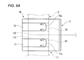
- FIG. 6A shows a fastening member 7B according to a second modification having such a configuration.
- a first fitting protrusion 71 and a third fitting protrusion 73 are shown as representatives.
- the engaging portion 71 a is provided on the first fitting protrusion 71, and the engaging portion 73 a is provided on the third fitting protrusion 73.
- the engaging part 71a and the engaging part 73a are, for example, flexible engaging claws. 6B, the engaging portion 71a engages with the front wall 11f of the first case 11 at the end of the first fitting groove 92, and the engaging portion 73a has the third fitting groove. 95 is engaged with the front wall 12f of the second case 12 at the end.
- similar engaging portions may be provided for the second fitting protrusion 72 and the fourth fitting protrusion 74 of the fastening member 7.
- any one of the engaging portion 71a and the engaging portion 73a can be omitted as long as the desired displacement regulating function can be exhibited.
- the moderation piece 4 is supported by the bracket 3 connected to the lever 2.
- the moderation piece 4 may be supported by a part of the lever 2.
- the coil spring 5 is used as an elastic member that biases the moderation piece 4 toward the moderation surface 6.
- a rod-like rubber member or the like can be appropriately employed.
Landscapes
- Engineering & Computer Science (AREA)
- Mechanical Engineering (AREA)
- Physics & Mathematics (AREA)
- General Physics & Mathematics (AREA)
- Automation & Control Theory (AREA)
- Lighting Device Outwards From Vehicle And Optical Signal (AREA)
- Mechanical Control Devices (AREA)
Abstract
ブラケット(3)は、レバー(2)の操作に応じて回動可能とされている。節度ピース(4)は、ブラケット(3)に連結されている。第一ケース(11)と第二ケース(12)は、ブラケット(3)と節度ピース(4)を収容する空間を区画している。締結部材(7)は、第一ケース(11)と第二ケース(12)を締結している。締結部材(7)は、節度ピース(4)が接触する節度面(6)を有している。
Description
本開示は、車両に搭載される方向指示機構、および当該方向指示機構の組立方法に関する。
特許文献1は、この種の方向指示機構の一例であるターンシグナルスイッチを開示している。ターンシグナルスイッチを構成する各種の部品は、スイッチケースとカバーにより区画される空間に収容されている。
特許文献1に記載されたターンシグナルスイッチにおいては、ねじによってカバーがスイッチケースに固定されている。この場合、部品点数が増加するだけでなく、ねじ締め工程が必要になるため、製造コストの上昇が避けられない。また、ねじ孔を形成する必要があるため、スイッチケースの大型化が避けられない。
したがって、方向指示機構の筐体の大型化と製造コストの上昇を抑制するという目的が存在する。
上記の目的を達成するための第一の態様は、車両に搭載される方向指示機構であって、
レバーの操作に応じて回動可能とされている回動部材と、
前記回動部材に連結されている節度ピースと、
前記回動部材と前記節度ピースを収容する空間を区画している第一ケースおよび第二ケースと、
前記第一ケースと前記第二ケースを締結している締結部材と、
を備えており、
前記締結部材は、前記節度ピースが接触する節度面を有している。
レバーの操作に応じて回動可能とされている回動部材と、
前記回動部材に連結されている節度ピースと、
前記回動部材と前記節度ピースを収容する空間を区画している第一ケースおよび第二ケースと、
前記第一ケースと前記第二ケースを締結している締結部材と、
を備えており、
前記締結部材は、前記節度ピースが接触する節度面を有している。
上記の目的を達成するための第二の態様は、車両に搭載される方向指示機構の組立方法であって、
レバーの操作に応じて回動可能とされている回動部材、および当該回動部材に連結されている節度ピースを収容する空間を区画するように、第一ケースと第二ケースを第一方向に結合し、
前記節度ピースが接触する節度面を有している締結部材を、前記第一ケースと前記第二ケースに対して前記第一方向と交差する第二方向に結合することにより、前記第一ケースと前記第二ケースを締結する。
レバーの操作に応じて回動可能とされている回動部材、および当該回動部材に連結されている節度ピースを収容する空間を区画するように、第一ケースと第二ケースを第一方向に結合し、
前記節度ピースが接触する節度面を有している締結部材を、前記第一ケースと前記第二ケースに対して前記第一方向と交差する第二方向に結合することにより、前記第一ケースと前記第二ケースを締結する。
このような構成によれば、第一ケースと第二ケースに締結部材を結合するという動作のみで両者の締結が完了する。また、締結部材は、方向指示機構にとって必須である節度面をその一部に有している。したがって、ねじ締めを要する製造方法と比較して部品点数の増加とねじ孔による筐体の大型化を抑制できるだけでなく、組立作業性が向上する。結果として、方向指示機構の筐体の大型化と製造コストの上昇を抑制できる。
上記の方向指示機構は、以下のように構成されうる。
前記第一ケースと前記第二ケースは第一方向に配列されており、
前記締結部材は、前記第一方向と交差する第二方向に延びている第一凸部と第二凸部を備えており、
前記第一凸部と前記第二凸部は、前記第一方向に配列されており、
前記第一ケースの一部と前記第二ケースの一部が、前記第一凸部と前記第二凸部の間に挟持されている。
前記第一ケースと前記第二ケースは第一方向に配列されており、
前記締結部材は、前記第一方向と交差する第二方向に延びている第一凸部と第二凸部を備えており、
前記第一凸部と前記第二凸部は、前記第一方向に配列されており、
前記第一ケースの一部と前記第二ケースの一部が、前記第一凸部と前記第二凸部の間に挟持されている。
このような構成によれば、筐体を構成する複数のケースをスナップフィットなどにより締結する構成と比較して、第一ケースと第二ケースをより堅固に締結できる。また、締結部材自身に節度面の位置決め機能を担わせることができる。節度面の位置が高い精度で定められることにより、節度ピースを介して回動部材の動作位置が高い精度で定まる。したがって、方向指示機構の筐体の大型化と製造コストの上昇を抑制できるだけでなく、当該筐体を構成する部品のがたつきを抑制し、回動部材の動作性を向上できる。
この場合、上記の方向指示機構は、以下のように構成されうる。
前記第一凸部と前記第二凸部は、前記第一方向における前記第一凸部と前記第二凸部の間隔が前記節度面から離れるに連れて狭くなっている部分を有している。
前記第一凸部と前記第二凸部は、前記第一方向における前記第一凸部と前記第二凸部の間隔が前記節度面から離れるに連れて狭くなっている部分を有している。
このような構成によれば、締結部材の第一ケースと第二ケースに対する結合が進行するに連れて、両ケースの一部を挟む第一凸部と第二凸部の間隔が狭まるため、当該両ケースの一部に対する締め付けが徐々に強くなっていく。これにより、第一ケースと第二ケースをより堅固に締結できる。したがって、方向指示機構の筐体を構成する部品のがたつきをさらに抑制できる。
上記の方向指示機構は、以下のように構成されうる。
前記節度ピースを前記節度面に向けて付勢している弾性部材を備えており、
前記締結部材は、前記節度ピースから離れる方向への変位を規制するように前記第一ケースと前記第二ケースの少なくとも一方と係合している係合部を備えている。
前記節度ピースを前記節度面に向けて付勢している弾性部材を備えており、
前記締結部材は、前記節度ピースから離れる方向への変位を規制するように前記第一ケースと前記第二ケースの少なくとも一方と係合している係合部を備えている。
このような構成によれば、弾性部材の付勢力により節度ピースが節度面に押し付けられることにより、締結部材が節度ピースから離れる方向へ変位することが防止される。これにより、方向指示機構の繰り返し使用に伴って締結部材による締結状態が維持できなくなることを防止できる。したがって、方向指示機構の筐体を構成する部品のがたつきをさらに抑制できる。
添付の図面を参照しつつ、実施形態例について以下詳細に説明する。以下の説明に用いる各図面では、各部材を認識可能な大きさとするために縮尺を適宜変更している。「前後」「左右」「上下」という表現は、説明の便宜のために用いており、実際の使用状態における姿勢や方向を限定する意図はない。
図1Aは、一実施形態に係る方向指示機構1の外観を示している。図1Bは、図1Aにおける線IB-IBに沿って方向指示機構1の一部を矢印方向から見た断面図である。図1Cは、図1Aにおける線IC-ICに沿って方向指示機構1の一部を矢印方向から見た断面図である。図2Aは、図1Aにおける線IIA-IIAに沿って方向指示機構1の一部を矢印方向から見た断面図である。以降の説明に用いられる「時計回り」「反時計回り」という表現は、図2Aにおける方向を基準とする。
方向指示機構1は、車両に搭載される。具体的には、車両の転舵を司るステアリングホイールに連結されたステアリングシャフトの側方に配置される。
図1Bと図1Cに示されるように、方向指示機構1は、レバー2を備えている。レバー2は、車両の転舵方向を示す方向指示灯を点消灯させるために運転者によって操作される。
方向指示機構1は、ブラケット3(回動部材の一例)を備えている。ブラケット3は、一対の回動軸31を備えている。ブラケット3は、レバー2と連結されている。ブラケット3は、レバー2の操作に応じて、一対の回動軸31を中心として時計回りおよび反時計回りに回動する。
方向指示機構1は、節度ピース4とコイルばね5(弾性部材の一例)を備えている。節度ピース4は、ブラケット3に対して変位可能に連結されている。具体的には、図1Bに示されるように、ブラケット3に形成された摺動穴32内に、節度ピース4の一部とコイルばね5が配置されている。節度ピース4は、コイルばね5の弾性変形に伴ってブラケット3の摺動穴32内を摺動可能とされている。
方向指示機構1は、節度面6を備えている。本実施形態においては、節度面6は、コイルばね5は、節度ピース4を節度面6へ向けて付勢している。これにより、節度ピース4は、節度面6に接触可能とされている。
図1Aから図1Cに示されるように、方向指示機構1は、第一ケース11と第二ケース12を備えている。第一ケース11と第二ケース12は、方向指示機構1の筐体を形成する。第一ケース11と第二ケース12は、ブラケット3、節度ピース4、コイルばね5、および節度面6を収容する空間を区画している。
方向指示機構1は、ラチェット8を備えている。図1Bと図2Aに示されるように、ラチェット8は、第一回動軸81を備えている。他方、ブラケット3は、ラチェット当接面33を有している。ラチェット8の第一回動軸81は、ラチェット当接面33に当接するように、ブラケット3と第二ケース12により保持されている。また、図1Bに示されるように、ラチェット8は、第二回動軸82を備えている。他方、第二ケース12には溝12aが形成されている。ラチェット8の第二回動軸82は、溝12a内を摺動可能に第二ケース12に保持されている。
ラチェット8の第一回動軸81は、コイルばねや板ばねなどの弾性部材(不図示)により、ブラケット3のラチェット当接面33に向けて付勢されている。
図2Aに示されるように、節度面6は、第一峰部61、第二峰部62、および中立保持部63を含んでいる。第一峰部61と第二峰部62は、谷部を形成するように接続されている。当該谷部によって中立保持部63が区画されている。ブラケット3が中立位置にあるとき、節度ピース4は、節度面6の中立保持部63に配置されている。
ブラケット3のラチェット当接面33は、第一当接面33aと第二当接面33bを含んでいる。第一当接面33aと第二当接面33bは、峰部33cを形成するように接続されている。
ラチェット8は、係合突起83を備えている。ブラケット3が中立位置にあるとき、ラチェット8の第一回動軸81は、ラチェット当接面の峰部33cに配置されている。このとき、係合突起83は、車両のステアリングシャフトに装着されたキャンセルカム(不図示)の回動軌跡から退避している。
左折時あるいは左車線への進路変更時には、回動軸31を中心としてブラケット3が反時計回りに回動するようにレバー2が操作される。図2Bは、この状態を示している。ブラケット3の回動に伴い、節度ピース4は、中立保持部63に隣接している第一峰部61を乗り越えるように移動する。このとき、節度ピース4は、コイルばね5を圧縮するようにブラケット3の摺動穴32内を摺動する。
ブラケット3が左折指示位置に到達すると、節度ピース4は、第一峰部61とコイルばね5の付勢力により、中立保持部63への戻りを阻止される。したがって、ブラケット3は、左折指示位置に保持される。
これにより、図示しないスイッチ機構を介して、車両の左折用方向指示器を点灯させるための信号が方向指示機構1から出力される。
他方、ラチェット8の第一回動軸81は、ラチェット当接面33の峰部33cから第一当接面33aに沿って移動する。ラチェット8は、上記の弾性部材の付勢力によってステアリングシャフトに向かって前進する。
ブラケット3が図2Bに示される左折指示位置に到達すると、ブラケット3の回動は、第一ケース11の内壁(あるいは当該内壁に設けられた突起などの規制部材)によって規制される。このとき、ラチェット8の係合突起83は、キャンセルカムの回動軌跡内に進入する。
ブラケット3が左折指示位置にある状態において、ステアリングホイールが右回転(時計回りの回転)されると、左折指示動作のキャンセルが行なわれる。具体的には、ステアリングホイールの右回転に伴い、ステアリングシャフトに装着されたキャンセルカムが時計回りに回動し、回動軌跡に進入しているラチェット8の係合突起83と係合する。ラチェット8は、回動軌跡に平行な面内において第一回動軸81と第二回動軸82を中心として回動可能とされている。したがって、反時計回りに回動するキャンセルカムの通過を許容するように、ラチェット8は、第一回動軸81と第二回動軸82を中心として反時計回りに回動する。
ラチェット8を介して伝達されるキャンセルカムの回動力は、図示しないキャンセル機構を介してブラケット3を時計回りに回動させる。節度ピース4は、節度面6の第一峰部61を乗り越えて中立保持部63へ移動する。これにより、車両の左折用方向指示器を点灯させるための信号の出力が停止される。
右折時あるいは右車線への進路変更時には、回動軸31を中心としてブラケット3が時計回りに回動するようにレバー2が操作される。ブラケット3の回動に伴い、節度ピース4は、中立保持部63に隣接している第二峰部62を乗り越えるように移動する。このとき、節度ピース4は、コイルばね5を圧縮するようにブラケット3の摺動穴32内を摺動する。
ブラケット3が右折指示位置に到達すると、節度ピース4は、第二峰部62とコイルばね5の付勢力により、中立保持部63への戻りを阻止される。したがって、ブラケット3は、左折指示位置に保持される。
これにより、図示しないスイッチ機構を介して、車両の右折用方向指示器を点灯させるための信号が方向指示機構1から出力される。
他方、ラチェット8の第一回動軸81は、ラチェット当接面33の峰部33cから第二当接面33bに沿って移動する。ラチェット8は、上記の弾性部材の付勢力によってステアリングシャフトに向かって前進する。
ブラケット3が右折指示位置に到達すると、ブラケット3の回動は、第一ケース11の内壁(あるいは当該内壁に設けられた突起などの規制部材)によって規制される。このとき、ラチェット8の係合突起83は、キャンセルカムの回動軌跡内に進入する。
ブラケット3が右折指示位置にある状態において、ステアリングホイールが左回転(反時計回りの回転)されると、右折指示動作のキャンセルが行なわれる。具体的には、ステアリングホイールの左回転に伴い、ステアリングシャフトに装着されたキャンセルカムが反時計回りに回動し、回動軌跡に進入しているラチェット8の係合突起83と係合する。したがって、反時計回りに回動するキャンセルカムの通過を許容するように、ラチェット8は、第一回動軸81と第二回動軸82を中心として時計回りに回動する。
ラチェット8を介して伝達されるキャンセルカムの回動力は、図示しないキャンセル機構を介してブラケット3を反時計回りに回動させる。節度ピース4は、節度面6の第二峰部62を乗り越えて中立保持部63へ移動する。これにより、車両の右折用方向指示器を点灯させるための信号の出力が停止される。
図1Aに示されるように、方向指示機構1は、締結部材7を備えている。締結部材7は、第一ケース11と第二ケース12を締結している。図1Bに示されるように、締結部材7は、上記の節度面6を有している。
図3Aは、締結部材7の外観を示す背面図である。図3Bは、締結部材7の外観を示す上面図である。図3Cは、締結部材7の外観を示す正面図である。図3Dは、締結部材7の外観を示す右側面図である。下面図および左側面図は、それぞれ上面図および右側面図と対称であるため、図示を省略している。
図4Aから図4Dは、方向指示機構1の組立方法を示している。図4Aと図4Cは、図1Aに対応する正面図である。図4Bと図4Dは、図1Bに対応する断面図である。
まず、図4Aと図4Bに示されるように、レバー2が連結され、節度ピース4とコイルばね5が装着された状態のブラケット3が、第一ケース11と結合される。次いで、図4Cと図4Dに示されるように、ラチェット8をブラケット3との間に挟持するように、上方から第二ケース12が第一ケース11と結合される。例えば、第一ケース11と第二ケース12の一方には図示しない係合穴が形成されており、他方には図示しない係合爪が形成されている。第一ケース11と第二ケース12の結合は、係合爪が係合穴と係合することによりなされる。
図4Aに示されるように、第一ケース11の前壁11fには、第一切欠部91、第一嵌合溝92、および第二嵌合溝93が形成されている。第一嵌合溝92と第二嵌合溝93は、それぞれ第一切欠部91に開口している。図4Bに示されるように、第二嵌合溝93は、第一ケース11の内部と外部を連通するように延びている。第一嵌合溝92も同様である。
図4Cに示されるように、第二ケース12の前壁12fには、第二切欠部94、第三嵌合溝95、および第四嵌合溝96が形成されている。第三嵌合溝95と第四嵌合溝96は、それぞれ第二切欠部94に開口している。図4Dに示されるように、第四嵌合溝96は、第二ケース12の内部と外部を連通するように延びている。第三嵌合溝95も同様である。
図4Cに示されるように、第一ケース11と第二ケース12が結合されると、第一切欠部91と第二切欠部94が嵌合穴97を区画する。嵌合穴97は、第一ケース11および第二ケース12の内部と外部を連通するように延びている。
図3Aから図3Dに示されるように、締結部材7は、第一嵌合突起71、第二嵌合突起72、第三嵌合突起73、および第四嵌合突起74を備えている。図4Cと図4Dに示された状態から、締結部材7が嵌合穴97に挿入される。このとき、第一嵌合突起71は、第一ケース11の第一嵌合溝92と嵌合する。第二嵌合突起72は、第一ケース11の第二嵌合溝93と嵌合する。第三嵌合突起73は、第二ケース12の第三嵌合溝95と嵌合する。第四嵌合突起74は、第二ケース12の第四嵌合溝96と嵌合する。
すなわち、締結部材7は、第一ケース11と第二ケース12に対し、これらの結合方向と交差する向きに結合される。これにより、図1Aから図1Cに示されるように、締結部材7は、第一ケース11と第二ケース12を締結する。
このような構成によれば、第一ケース11と第二ケース12に締結部材7を結合するという動作のみで両者の締結が完了する。また、締結部材7は、方向指示機構1にとって必須である節度面6をその一部に有している。したがって、ねじ締めを要する製造方法と比較して部品点数の増加とねじ孔による筐体の大型化を抑制できるだけでなく、組立作業性が向上する。結果として、方向指示機構1の筐体の大型化と製造コストの上昇を抑制できる。
図1Aと図1Cに示されるように、第一ケース11と第二ケース12は、上下方向(第一方向の一例)に配列されている。締結部材7の第一嵌合突起71と第二嵌合突起72(第一凸部の一例)は、前後方向および左右方向(第二方向の一例)に延びている。同様に、締結部材7の第三嵌合突起73と第四嵌合突起74(第二凸部の一例)は、前後方向および左右方向(第二方向の一例)に延びている。第一嵌合突起71と第三嵌合突起73は、上下方向に配列されている。同様に、第二嵌合突起72と第四嵌合突起74は、上下方向に配列されている。
締結部材7により第一ケース11と第二ケース12が締結された状態において、第一ケース11の前壁11fの一部と第二ケース12の前壁12fの一部は、第一嵌合突起71と第三嵌合突起73の間に挟持されている。同様に、第一ケース11の前壁11fの別の一部と第二ケース12の前壁12fの別の一部は、第二嵌合突起72と第四嵌合突起74の間に挟持されている。
このような構成によれば、筐体を構成する複数のケースをスナップフィットなどにより締結する構成と比較して、第一ケース11と第二ケース12をより堅固に締結できる。また、締結部材7自身に節度面6の位置決め機能を担わせることができる。節度面6の位置が高い精度で定められることにより、節度ピース4を介してブラケット3の中立位置と方向指示位置が高い精度で定まる。したがって、方向指示機構1の筐体の大型化と製造コストの上昇を抑制できるだけでなく、当該筐体を構成する部品のがたつきを抑制し、ブラケット3の動作性を向上できる。
上記の実施形態は、本開示の理解を容易にするための例示にすぎない。上記の実施形態に係る構成は、本開示の趣旨を逸脱しなければ、適宜に変更・改良されうる。また、等価物が本開示の技術的範囲に含まれることは明らかである。
上記の実施形態においては、締結部材7は、第一ケース11と嵌合する部材として第一嵌合突起71と第二嵌合突起72を備えており、第二ケース12と嵌合する部材として第三嵌合突起73と第四嵌合突起74を備えている。しかしながら、第一ケース11と第二ケース12に対して所望の締結機能を発揮できるのであれば、第一嵌合突起71および第三嵌合突起73の対と第二嵌合突起72および第四嵌合突起74の対のいずれか一方は省略されうる。
上記の実施形態においては、第一嵌合突起71と第三嵌合突起73の上下方向における間隔は、前後方向について一定である。同様に、第二嵌合突起72と第四嵌合突起74の上下方向における間隔は、前後方向について一定である。しかしながら、第一嵌合突起71と第三嵌合突起73は、上下方向における両者の間隔が節度面6から離れるに連れて狭くなる部分を有していてもよい。同様に、第二嵌合突起72と第四嵌合突起74は、上下方向における両者の間隔が節度面6から離れるに連れて狭くなる部分を有していてもよい。図5Aは、このような構成を有する第一の変形例に係る締結部材7Aを示している。同図においては、第一嵌合突起71と第三嵌合突起73が代表して示されている。
より具体的には、第一嵌合突起71と第三嵌合突起73の上下方向における間隔寸法が、節度面6から離れるに連れて両者に挟まれる第一ケース11の前壁11fの一部と第二ケース12の前壁12fの一部の厚みの合計寸法よりも小さくなる部分を有している。
この場合、締結部材7が第一ケース11と第二ケース12に対する結合される際には、二点鎖線で示される第一ケース11の第一嵌合溝92と第二ケース12の第三嵌合溝95に沿って締結部材7の第一嵌合突起71と第三嵌合突起73が摺動する。結合が進行するに連れて、前壁11fの一部と前壁12fの一部を挟む第一嵌合突起71と第三嵌合突起73の間隔が狭まるため、前壁11fの一部と前壁12fの一部に対する締め付けが徐々に強くなっていく。
図5Bに示される締結の完了時においては、前壁11fの一部と前壁12fの一部を僅かに圧縮変形させつつ、第一嵌合突起71と第三嵌合突起73による挟持がなされる。これにより、第一ケース11と第二ケース12をより堅固に締結できる。したがって、方向指示機構1の筐体を構成する部品のがたつきをさらに抑制できる。
締結部材7は、節度ピース4から離れる方向への変位を規制するように第一ケース11および第二ケース12と係合可能な係合部を備えうる。図6Aは、このような構成を有する第二の変形例に係る締結部材7Bを示している。同図においては、第一嵌合突起71と第三嵌合突起73が代表して示されている。
より具体的には、第一嵌合突起71に係合部71aが設けられており、第三嵌合突起73に係合部73aが設けられている。係合部71aと係合部73aは、例えば、柔軟性を有する係合爪である。図6Bに示される締結完了状態において、係合部71aは、第一嵌合溝92の端部において第一ケース11の前壁11fと係合し、係合部73aは、第三嵌合溝95の端部において第二ケース12の前壁12fと係合する。図示を省略するが、締結部材7の第二嵌合突起72と第四嵌合突起74についても同様の係合部が設けられうる。
このような構成によれば、コイルばね5の付勢力により節度ピース4が節度面6に押し付けられることにより、締結部材7が節度ピース4から離れる方向へ変位することが防止される。これにより、方向指示機構1の繰り返し使用に伴って締結部材7による締結状態が維持できなくなることを防止できる。したがって、方向指示機構1の筐体を構成する部品のがたつきをさらに抑制できる。
所望の変位規制機能を発揮できるのであれば、係合部71aと係合部73aのいずれか一方は省略されうる。
上記の実施形態においては、レバー2に連結されたブラケット3に節度ピース4が支持されている。しかしながら、節度ピース4は、レバー2の一部に支持されてもよい。
上記の実施形態においては、節度ピース4を節度面6に向けて付勢する弾性部材としてコイルばね5が用いられている。しかしながら、節度ピース4の摺動方向への弾性変形と当該摺動方向に交差する向きへの弾性変形が可能であれば、棒状のゴム部材などが適宜に採用されうる。
本出願の記載の一部を構成するものとして、2015年12月15日に提出された日本国特許出願2015-244158の内容を援用する。
Claims (5)
- 車両に搭載される方向指示機構であって、
レバーの操作に応じて回動可能とされている回動部材と、
前記回動部材に連結されている節度ピースと、
前記回動部材と前記節度ピースを収容する空間を区画している第一ケースおよび第二ケースと、
前記第一ケースと前記第二ケースを締結している締結部材と、
を備えており、
前記締結部材は、前記節度ピースが接触する節度面を有している、
方向指示機構。 - 前記第一ケースと前記第二ケースは第一方向に配列されており、
前記締結部材は、前記第一方向と交差する第二方向に延びている第一凸部と第二凸部を備えており、
前記第一凸部と前記第二凸部は、前記第一方向に配列されており、
前記第一ケースの一部と前記第二ケースの一部が、前記第一凸部と前記第二凸部の間に挟持されている、
請求項1に記載の方向指示機構。 - 前記第一凸部と前記第二凸部は、前記第一方向における前記第一凸部と前記第二凸部の間隔が前記節度面から離れるに連れて狭くなっている部分を有している、
請求項2に記載の方向指示機構。 - 前記節度ピースを前記節度面に向けて付勢している弾性部材を備えており、
前記締結部材は、前記節度ピースから離れる方向への変位を規制するように前記第一ケースと前記第二ケースの少なくとも一方と係合している係合部を備えている、
請求項1から3のいずれか一項に記載の方向指示機構。 - レバーの操作に応じて回動可能とされている回動部材、および当該回動部材に連結されている節度ピースを収容する空間を区画するように、第一ケースと第二ケースを第一方向に結合し、
前記節度ピースが接触する節度面を有している締結部材を、前記第一ケースと前記第二ケースに対して前記第一方向と交差する第二方向に結合することにより、前記第一ケースと前記第二ケースを締結する、
車両に搭載される方向指示機構の組立方法。
Applications Claiming Priority (2)
| Application Number | Priority Date | Filing Date | Title |
|---|---|---|---|
| JP2015244158A JP2017109548A (ja) | 2015-12-15 | 2015-12-15 | 方向指示機構、および方向指示機構の組立方法 |
| JP2015-244158 | 2015-12-15 |
Publications (1)
| Publication Number | Publication Date |
|---|---|
| WO2017104435A1 true WO2017104435A1 (ja) | 2017-06-22 |
Family
ID=59056356
Family Applications (1)
| Application Number | Title | Priority Date | Filing Date |
|---|---|---|---|
| PCT/JP2016/085802 Ceased WO2017104435A1 (ja) | 2015-12-15 | 2016-12-01 | 方向指示機構、および方向指示機構の組立方法 |
Country Status (2)
| Country | Link |
|---|---|
| JP (1) | JP2017109548A (ja) |
| WO (1) | WO2017104435A1 (ja) |
Cited By (1)
| Publication number | Priority date | Publication date | Assignee | Title |
|---|---|---|---|---|
| CN113632309A (zh) * | 2018-12-13 | 2021-11-09 | 株式会社Lg新能源 | 电池模块 |
Citations (2)
| Publication number | Priority date | Publication date | Assignee | Title |
|---|---|---|---|---|
| JPH08167345A (ja) * | 1994-12-12 | 1996-06-25 | Matsushita Electric Ind Co Ltd | ターンシグナルスイッチのキャンセル装置 |
| JP2010277711A (ja) * | 2009-05-26 | 2010-12-09 | Teikoku Tsushin Kogyo Co Ltd | クリック機構及び回転式電子部品 |
-
2015
- 2015-12-15 JP JP2015244158A patent/JP2017109548A/ja active Pending
-
2016
- 2016-12-01 WO PCT/JP2016/085802 patent/WO2017104435A1/ja not_active Ceased
Patent Citations (2)
| Publication number | Priority date | Publication date | Assignee | Title |
|---|---|---|---|---|
| JPH08167345A (ja) * | 1994-12-12 | 1996-06-25 | Matsushita Electric Ind Co Ltd | ターンシグナルスイッチのキャンセル装置 |
| JP2010277711A (ja) * | 2009-05-26 | 2010-12-09 | Teikoku Tsushin Kogyo Co Ltd | クリック機構及び回転式電子部品 |
Cited By (3)
| Publication number | Priority date | Publication date | Assignee | Title |
|---|---|---|---|---|
| CN113632309A (zh) * | 2018-12-13 | 2021-11-09 | 株式会社Lg新能源 | 电池模块 |
| CN113632309B (zh) * | 2018-12-13 | 2023-10-24 | 株式会社Lg新能源 | 电池模块、包括电池模块的电池组和包括电池组的装置 |
| US12506228B2 (en) | 2018-12-13 | 2025-12-23 | Lg Energy Solution, Ltd. | Battery module |
Also Published As
| Publication number | Publication date |
|---|---|
| JP2017109548A (ja) | 2017-06-22 |
Similar Documents
| Publication | Publication Date | Title |
|---|---|---|
| US7332684B2 (en) | Turn signal switch for vehicle | |
| US10935126B2 (en) | Shift device | |
| JP2015105710A (ja) | ボールねじおよびパワーステアリング装置 | |
| GB2524626A (en) | Steering apparatus | |
| US9865945B2 (en) | Attachment structure for housing | |
| WO2017090327A1 (ja) | パワーステアリング装置 | |
| WO2017104435A1 (ja) | 方向指示機構、および方向指示機構の組立方法 | |
| JP2006067694A (ja) | アクチュエータ装置 | |
| US10266052B2 (en) | Steering column assembly having a shift gate assembly | |
| JP6934625B2 (ja) | 複合操作入力装置 | |
| JP2006067695A (ja) | アクチュエータ装置 | |
| JP4834475B2 (ja) | 回転コネクタ装置とコンビスイッチの取付構造 | |
| US20140000404A1 (en) | Shift lever device | |
| KR101670367B1 (ko) | 멀티펑션 스위치 어셈블리 | |
| JPWO2015151882A1 (ja) | スイッチ装置 | |
| WO2018079109A1 (ja) | 方向指示機構 | |
| JP4256276B2 (ja) | 車両用方向指示装置 | |
| US10622173B2 (en) | Rocker switch device | |
| JP2017103177A (ja) | 方向指示機構 | |
| US9550451B2 (en) | Case-equipped mechanism device | |
| JP6451951B2 (ja) | 車両用ドアのアウトハンドル装置 | |
| WO2018079108A1 (ja) | 方向指示機構 | |
| WO2017138460A1 (ja) | スイッチ機構 | |
| WO2018168408A1 (ja) | シフト装置 | |
| JP4300152B2 (ja) | 回転式操作装置のスイッチ機構 |
Legal Events
| Date | Code | Title | Description |
|---|---|---|---|
| 121 | Ep: the epo has been informed by wipo that ep was designated in this application |
Ref document number: 16875418 Country of ref document: EP Kind code of ref document: A1 |
|
| NENP | Non-entry into the national phase |
Ref country code: DE |
|
| 122 | Ep: pct application non-entry in european phase |
Ref document number: 16875418 Country of ref document: EP Kind code of ref document: A1 |