WO2017104389A1 - 複合型電気接続装置 - Google Patents
複合型電気接続装置 Download PDFInfo
- Publication number
- WO2017104389A1 WO2017104389A1 PCT/JP2016/085154 JP2016085154W WO2017104389A1 WO 2017104389 A1 WO2017104389 A1 WO 2017104389A1 JP 2016085154 W JP2016085154 W JP 2016085154W WO 2017104389 A1 WO2017104389 A1 WO 2017104389A1
- Authority
- WO
- WIPO (PCT)
- Prior art keywords
- short
- terminal
- circuit
- connector
- female
- Prior art date
- Legal status (The legal status is an assumption and is not a legal conclusion. Google has not performed a legal analysis and makes no representation as to the accuracy of the status listed.)
- Ceased
Links
Images


Classifications
-
- H—ELECTRICITY
- H01—ELECTRIC ELEMENTS
- H01R—ELECTRICALLY-CONDUCTIVE CONNECTIONS; STRUCTURAL ASSOCIATIONS OF A PLURALITY OF MUTUALLY-INSULATED ELECTRICAL CONNECTING ELEMENTS; COUPLING DEVICES; CURRENT COLLECTORS
- H01R31/00—Coupling parts supported only by co-operation with counterpart
- H01R31/08—Short-circuiting members for bridging contacts in a counterpart
-
- H—ELECTRICITY
- H01—ELECTRIC ELEMENTS
- H01R—ELECTRICALLY-CONDUCTIVE CONNECTIONS; STRUCTURAL ASSOCIATIONS OF A PLURALITY OF MUTUALLY-INSULATED ELECTRICAL CONNECTING ELEMENTS; COUPLING DEVICES; CURRENT COLLECTORS
- H01R13/00—Details of coupling devices of the kinds covered by groups H01R12/70 or H01R24/00 - H01R33/00
- H01R13/40—Securing contact members in or to a base or case; Insulating of contact members
- H01R13/42—Securing in a demountable manner
- H01R13/436—Securing a plurality of contact members by one locking piece or operation
- H01R13/4361—Insertion of locking piece perpendicular to direction of contact insertion
-
- H—ELECTRICITY
- H01—ELECTRIC ELEMENTS
- H01R—ELECTRICALLY-CONDUCTIVE CONNECTIONS; STRUCTURAL ASSOCIATIONS OF A PLURALITY OF MUTUALLY-INSULATED ELECTRICAL CONNECTING ELEMENTS; COUPLING DEVICES; CURRENT COLLECTORS
- H01R13/00—Details of coupling devices of the kinds covered by groups H01R12/70 or H01R24/00 - H01R33/00
- H01R13/46—Bases; Cases
- H01R13/502—Bases; Cases composed of different pieces
- H01R13/506—Bases; Cases composed of different pieces assembled by snap action of the parts
-
- H—ELECTRICITY
- H01—ELECTRIC ELEMENTS
- H01R—ELECTRICALLY-CONDUCTIVE CONNECTIONS; STRUCTURAL ASSOCIATIONS OF A PLURALITY OF MUTUALLY-INSULATED ELECTRICAL CONNECTING ELEMENTS; COUPLING DEVICES; CURRENT COLLECTORS
- H01R13/00—Details of coupling devices of the kinds covered by groups H01R12/70 or H01R24/00 - H01R33/00
- H01R13/46—Bases; Cases
- H01R13/514—Bases; Cases composed as a modular blocks or assembly, i.e. composed of co-operating parts provided with contact members or holding contact members between them
-
- H—ELECTRICITY
- H01—ELECTRIC ELEMENTS
- H01R—ELECTRICALLY-CONDUCTIVE CONNECTIONS; STRUCTURAL ASSOCIATIONS OF A PLURALITY OF MUTUALLY-INSULATED ELECTRICAL CONNECTING ELEMENTS; COUPLING DEVICES; CURRENT COLLECTORS
- H01R2107/00—Four or more poles
Definitions
- the present invention is a composite electrical connection having both a short-circuit function for short-circuiting three or more short-circuit target wires and an interconnect function for connecting specific wires different from the short-circuit target wires one-to-one. Relates to the device.
- Patent Document 1 discloses a short-circuit bus bar that connects a plurality of tab-shaped terminals to each other, and a connector that holds the tab-shaped terminals and the bus bar in a posture in which the tab-shaped terminals are arranged in a horizontal row.
- a connector comprising a housing is disclosed.
- a conventional general connector that is, a male terminal and a female terminal respectively connected to the ends of the electric wires to be interconnected, and a male connector housing for holding the male terminal And a female connector housing for holding the female terminal, and connecting the electric wires to each other by fitting the male terminal and the female terminal is used.
- the present invention is a composite electric that enables both short-circuiting of three or more electric wires and one-to-one interconnection of specific electric wires with a compact structure and efficient work.
- An object is to provide a connection device.
- the device includes a first connector and a second connector that can be fitted to the first connector in a specific connector fitting direction.
- the first connector has a female electrical contact portion and has a first short-circuit female terminal attached to a part of the terminals of the plurality of short-circuited wires, and a female electrical contact portion.
- the electrical contact portions of the interconnecting female terminal attached to one end of the interconnect target wires, the first short-circuiting female terminal, and the interconnecting female terminal are all the same.
- the second connector has a female electrical contact portion, and is for a second short circuit that is attached to a terminal of an electric wire other than the electric wire to which the first short-circuit female terminal is attached among the plurality of short-circuited electric wires.
- An interconnecting male that has a female terminal and a male electrical contact portion that can be engaged with the electrical contact portion of the interconnecting female terminal and is attached to the other end of the interconnect target wires And a first terminal projecting from the base and a plurality of female terminals including the first short-circuit female terminal and the second short-circuit female terminal.
- a first male terminal having a shape that protrudes in a direction and fits into an electrical contact portion of the first short-circuiting female terminal; and a second protruding direction opposite to the first protruding direction from the base and the first protruding terminal. Integrating the second male terminal portion having a shape that can be fitted into the electrical contact portion of the second short-circuit female terminal And a short circuit for short-circuiting the first short-circuit female terminal fitted to the first male terminal and the second short-circuit female terminal fitted to the second male terminal. And a second connector housing that can be fitted in the first connector housing and the connector fitting direction. The second connector housing is held by the first connector housing when the first connector housing is fitted to the housing fitting portion and the housing fitting portion to be fitted to the first connector housing.
- the first short-circuit female terminal is disengaged from the short-circuit member in a direction perpendicular to the connector fitting direction, and a short-circuit member holding portion that holds the short-circuit member at a position where the first short-circuit female terminal is fitted to the first male terminal portion.
- the female terminal for interconnection held by the first connector housing is fitted to the male terminal for interconnection.
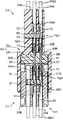
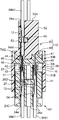
- FIG. 4 is a side view showing a cross section taken along line IV-IV in FIG. 3.
- FIG. 5 is a side view showing a cross section taken along line VV in FIG. 3.
- FIG. 4 is a side view showing a cross section taken along line VI-VI in FIG. 3.
- FIG. 4 is a bottom view showing a cross section taken along line VII-VII in FIG. 3.
- FIG. 4 is a bottom view showing a cross section taken along line VIII-VIII in FIG. 3.
- FIG. 4 is a side view showing a cross section taken along line VIII-VIII in FIG. 3.
- FIG. 4 is a bottom view showing a cross section taken along line IV-IV in FIG. 3. It is a perspective view which shows the 1st connector housing of the said electrical connection apparatus. It is a front view which shows the said 1st connector housing. It is a perspective view which shows the short circuit member of the said electrical connection apparatus, and the short circuit member holding member holding this. It is a front view which shows the said short circuit member and the said short circuit member holding member.
- FIG. 14 is a side view showing a cross section taken along line XIV-XIV in FIG. 13.
- FIG. 14 is a side view showing a cross section taken along line XV-XV in FIG. 13.
- This composite electrical connecting device has a function of mutually short-circuiting three or more (total of eight in this embodiment) short-circuited electric wires and the short-circuited electric wires (three sets in this embodiment). And an interconnection function for connecting the interconnection target wires to each other one to one.
- the electrical connection device includes a first connector C1 and a second connector C2.
- the second connector C2 can be fitted to the first connector C1 in a specific connector fitting direction, in the horizontal direction in the posture shown in each drawing, and the respective connections are collectively performed by the fitting. .
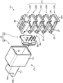
- the first connector C1 includes a plurality of first short-circuit female terminals TS1, a plurality of interconnection female terminals TM1, and a first connector housing H1.
- the first short-circuit female terminal TS1 is a part of a plurality of short-circuit target wires (in this embodiment, a total of six short-circuit target wires; hereinafter, “first short-circuit target wires”). It is attached to each terminal of WS1.
- the interconnection female terminal TM1 is one of the sets of interconnection target wires (in this embodiment, a total of three interconnection target wires; hereinafter referred to as “first interconnection target wires”). ) It is attached to each terminal of WM1.
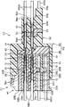
- each female terminal TS1, TM1 integrally has a female electrical contact portion 10 as shown in FIGS. 4 to 9 and a crimping portion 12 located behind the female contact portion 10.
- the crimping portion 12 has a barrel that is crimped so as to embrace the conductor portion exposed at the end of each of the electric wires WS1 and WM1 and the insulating coating portion behind the conductor portion.
- the crimping part 12 enables electrical conduction between the conductor part and the female terminals TS1, TM2 by being crimped to the conductor part.
- the electrical contact portions of the plurality of first short-circuit female terminals TS1 and the plurality of interconnection female terminals TM1 all have the same direction (direction along the connector fitting direction).
- the first short-circuit female terminal TS1 and the interconnection female terminal TM1 are held in a posture to face.
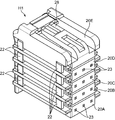
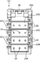
- the first connector housing H1 is divided into a plurality of housing elements 20A, 20B, 20C, 20D and 20E.
- Each of the housing elements 20A to 20E is formed as a separate member from an insulating material such as a synthetic resin.
- These housing elements 20A to 20E are stacked in a direction perpendicular to the connector fitting direction (in this embodiment, the vertical direction; hereinafter referred to as “connector longitudinal direction” for convenience in this embodiment) and mutually.
- the housing elements 20A to 20E are stacked from the bottom in that order.
- each of the housing elements 20A to 20D has a pair of holding pieces 22, and the pair of holding pieces 22 hold the housing elements 20B to 20E which are respectively superimposed on the holding pieces 22 so as to embrace them.
- the first connector housing according to the present invention is not limited to such a split type.
- the first connector housing may be integrally molded as a whole.
- the housing elements 20A to 20D each have a plurality of terminal accommodating chambers 24 having the same shape.
- the plurality of terminal accommodating chambers 24 in the housing elements 20A to 20D are arranged in a direction perpendicular to the connector fitting direction and the direction in which the housing elements 20A to 20E are stacked (horizontal direction perpendicular to the connector fitting direction; In this embodiment, it is referred to as “connector lateral direction” for convenience.)
- Each terminal accommodating chamber 24 is a terminal that opens at the end of the first connector housing H1 and on the end opposite to the second connector C2 (hereinafter referred to as the rear end of the first connector housing H1).
- An insertion port 24a is provided, and the insertion of the first short-circuit female terminal TS1 or the interconnection female terminal TM1 along the connector fitting direction through the terminal insertion port 24a is received.
- the housing elements 20A to 20D are formed with a plurality of terminal locking portions (lances) (not shown) corresponding to the terminal housing chambers 24, respectively.
- Each terminal locking portion has a function of engaging and holding the female terminal TM1 or TS1 inserted into the corresponding terminal accommodating chamber 24.
- the positions where the terminals TS1, TM1 are held in the terminal accommodating chambers 24 are such that all the electrical contact portions 10 of the terminals TS1, TM1 are the end portions of the first connector housing H1, and the second connector C2.
- a terminal arrangement direction (the connector longitudinal direction and the connector lateral direction) orthogonal to the connector fitting direction at the end portion close to the connector (hereinafter referred to as the front end portion of the first connector housing H1). Is set.
- the number of first connector housings H1 is greater than the total number (nine in this embodiment) of the first short-circuit female terminals TS1 and the interconnection female terminals TM1. 12 terminal storage chambers 24 in total. A part of the terminal accommodating chambers 24 is selected, and the female terminal TS1 or TM1 is inserted and accommodated only in the terminal accommodating chamber 24.
- the housing elements 20B, 20C, 20D and 20E except the lowermost housing element 20A have secondary locking protrusions 26B, 26C, 26D and 26E which protrude downward from the bottom surface. Is formed.
- the secondary locking protrusions 26B to 26B of the housing elements 20B to 20E immediately above the housing elements 20A to 20E are combined.
- a protrusion insertion opening 27 for receiving insertion from above 26E is formed.
- Each of the secondary locking projections 26B to 26E is inserted into the housing elements 20A to 20D through the projection insertion port 27, whereby the female terminal accommodated in the terminal accommodating chamber 24 of the housing elements 20A to 20D.
- the female terminal TS1 or TM1 is secondarily locked (locked in addition to the locking by the lance) by engaging with an appropriate part of TS1 or TM1.
- the secondary locking is not essential in the present invention.
- the lance may be omitted and each terminal may be held only by the secondary locking projections 26B to 26E.
- the specific mode of holding the terminal in the first connector housing is not limited.
- the uppermost housing element 20E among the housing elements 20A to 20E is formed with a locked piece 28.
- the to-be-latched piece 28 can be elastically bent and displaced downward, and by using this, the fitting of the first and second connectors C1 and C2 is locked as will be described later.
- the second connector C1 includes a plurality of second short-circuit female terminals TS2, a plurality of interconnection male terminals TM2, a first short-circuit member SA, a second short-circuit member SB, 2 connector housings H2.
- the second short-circuit female terminal TS2 is composed of a plurality of short-circuit target wires excluding the first short-circuit target wire WS1 among the plurality of short-circuit target wires (a total of two short-circuit target wires in this embodiment; It is referred to as “2 short-circuited electric wire.”) Each is attached to the terminal of WS2.
- the male terminal TM2 for interconnection is the other of the sets of interconnection target wires (in this embodiment, a total of three interconnection target wires; hereinafter referred to as “second interconnection target wires”). ) Connected to the terminal of WM2.
- each second short-circuit female terminal TS2 has the same shape as the first short-circuit female terminal TS1, that is, the female electrical contact portion 10 and the crimping portion 12 located behind the female contact portion 10. It has a shape that it has integrally.
- each male terminal TM2 for interconnection has a male electrical contact portion 10 and a crimping portion 12 located behind it.
- the male electrical contact portion 10 has a shape that can be fitted into the female electrical contact portion 10 of the female terminal for interconnection TM1 in a close contact state.
- the electrical contact portions 10 and 11 enable the electrical connection between the interconnecting female terminal TM1 and the interconnecting male terminal TM2 by their mutual fitting.
- the crimping part 12 of the second short-circuit female terminal TS2 and the interconnection male terminal TM2 is a conductor exposed at the end of the corresponding electric wire WS2, WM2, like each terminal TS1, TM1 of the first connector C1.
- a barrel which is crimped so as to embrace the portion and the insulating coating portion behind the portion, and the conductor portion can be electrically connected to the female terminal TS2 or the male terminal TM2 by being crimped to the conductor portion. To do.
- Each of the first short-circuit member SA and the second short-circuit member SB is made of a conductor (metal plate), and includes the plurality of first short-circuit female terminals TS1 and the plurality of second short-circuit female terminals TS2.
- a short circuit for short-circuiting the plurality of female terminals TS1, TS2 selected from the female terminal group is formed.
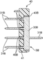
- the first short-circuit member SA includes a single base portion 30A and a plurality of (two in this embodiment) first male terminal portions 31A.
- the second male terminal portion 31B (one in this embodiment) is integrally provided.
- the second short-circuit member SB includes a single base portion 30A, a plurality of (four in this embodiment) first male terminal portions 31A, and a second male (one in this embodiment). And a mold terminal portion 31B.
- the first and second short-circuit members SA and SB are held by the second connector housing H2 so as to be aligned with each other in the connector width direction in an upright posture.
- the base portions 30A and 30B of the first and second short-circuit members SA and SB each have a rectangular plate shape extending in the vertical direction in this embodiment.
- Each of the first male terminal portions 31A, 31B protrudes in a first protruding direction (leftward in FIGS. 4 to 6) from the base portions 30A, 30B toward the first connector C1, and each of the first male terminal portions 31A, 31B.
- 1 Short-circuit female terminal TS1 has a shape that can be fitted into female electrical contact portion 10 of TS1.
- each of the second male terminal portions 32A, 32B protrudes from the base portions 30A, 30B in a second protruding direction opposite to the first protruding direction, and makes electrical contact with the second short-circuit female terminal TS2. It has a shape that can be fitted into the portion 10.
- the first short-circuit member SA is fitted to each first short-circuit female terminal TS1 and each second male terminal portion 32A that are fitted to each first male terminal portion 31A.
- Each of the second short-circuit female terminals TS2 is short-circuited to each other.
- the second short-circuit member SB is fitted to each first short-circuit female terminal TS1 fitted to each first male terminal portion 31B and each second male terminal portion 32B.
- a short circuit for short-circuiting the second short-circuit female terminals TS2 is formed.
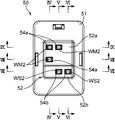
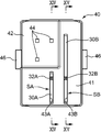
- the second connector housing H2 includes a short-circuit member holding member 40 and a housing body 50.
- the short-circuit member holding member 40 and the housing body 50 are molded as separate members from each other by an insulating material such as synthetic resin.
- the short-circuit member holding member 40 is attached to the housing main body 50 while holding the first short-circuit member SA and the second short-circuit member SB, so that the first short-circuit member SA and the second short-circuit member SB are attached.
- the second connector housing H2 is positioned in a predetermined posture at a predetermined position.
- the housing body 50 includes a hood 51 and a terminal holding part 52.
- the hood 51 is a housing fitting portion having a shape into which the first connector housing H1 can be fitted, and an end of the hood 51 is provided with the locked portion of the connector housing H1.
- a locking projection 58 that locks the fitted state by engaging with the piece 28 is formed.
- the terminal holding part 52 is connected to the hood 51 in a direction parallel to the connector fitting direction, and holds the plurality of second short-circuit female terminals TS2 and the plurality of interconnection male terminals TM2. .
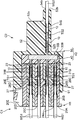
- the short-circuit member holding member 40 has a substantially rectangular plate shape, and integrally includes a short-circuit member holding portion 41 and a male terminal insertion allowing portion 42.
- the short-circuit member holding portion 41 includes a first base press-fit groove 43A, a second base press-fit groove 43B, and a plurality of (two in this embodiment) male terminal portion insertion holes connected to the first base press-fit groove 43A. 45A and a plurality (four in this embodiment) of male terminal portion insertion holes 45B connected to the second short-circuit member press-fitting groove 43B.
- the first base press-fitting groove 43A has a shape that allows the base 30A of the first short-circuit member SA to be press-fitted into the first base press-fitting groove 43A and that is elongated in the vertical direction.
- the plurality of male terminal insertion holes 45A are inserted into the first male terminal insertion holes 45A as the base 30A of the first short-circuit member SA is press-fitted into the first base press-fitting grooves 43A.
- Each first male terminal portion 31 ⁇ / b> A of the short-circuit member SA has a shape that allows the first male terminal portion 31 ⁇ / b> A to be inserted and protrude from the short-circuit member holding portion 41. In this manner, the short-circuit member holding portion 41 has a posture in which the base 30A of the first short-circuit member SA extends in the vertical direction and the plurality of first male terminal portions 31A are aligned in the vertical direction. ,Hold.
- the second base press-fitting groove 43B is formed at a position adjacent to the first base press-fitting groove 43A in the connector lateral direction (left-right direction in FIG. 13), and the second short-circuit member SB in the second base press-fitting groove 43B.
- the base portion 30B has a shape that can be press-fitted and that is elongated in the vertical direction.
- the plurality of male terminal portion insertion holes 45B are formed in the second terminal insertion holes 45B as the base portion 30B of the second short-circuit member SB is press-fitted into the second base press-fit grooves 43B.
- Each of the first male terminal portions 31 ⁇ / b> B of the short-circuit member SB is inserted and protrudes from the short-circuit member holding portion 41. In this manner, the short-circuit member holding portion 41 is configured such that the base 30B of the second short-circuit member SB extends in the vertical direction and the plurality of first male terminal portions 31B are aligned in the vertical direction. ,H
- the male terminal insertion allowing portion 42 is located away from the short-circuit member holding portion 41 in a direction orthogonal to the connector fitting direction, and the plurality of interconnection terminals regardless of the presence of the short-circuit member holding member 40.
- the male terminal TM2 has a shape that allows the male electrical contact portion 11 to be inserted.
- the male terminal insertion allowing portion 42 has a thickness smaller than the thickness of the short-circuit member holding portion 41 and a plurality of penetrating male terminal insertion allowing portions 42 in the thickness direction.
- a male terminal insertion hole 44 is provided, and each male terminal insertion hole 44 has a shape that allows insertion of the electrical contact portion 11 of each of the interconnection male terminals TM2.
- the short-circuit member holding member 41 has a pair of latching protrusions 46 projecting on both sides thereof, and the latching protrusions 46 are formed at the rear end of the hood 51 of the housing body 50 as shown in FIG. The formed step 56 is locked. Thereby, the short-circuit member holding member 41 is fixed in the housing body 50.
- the short-circuit member holding member 41 is connected to the first and second short-circuit members SA and SB.
- the electrical contact portions 11 of the single male terminal portions 31A and 31B protrude into the hood 51 and are aligned in the hood 51 in a direction (connector longitudinal direction and connector lateral direction) perpendicular to the connector fitting direction.
- the first and second short-circuit members SA and SB are positioned.
- the positions of the first and second short-circuit members SA and SB are such that the first connector housing H1 is in a proper position in the hood 51 (the locked piece 28 of the first connector housing H1 is the end of the hood 51).
- first and second electrical terminals 10 of the first short-circuit female terminals TS1 held in the first connector housing H1 when the first contact housing H1 is inserted into the first projection housing 58.
- the first male terminal portions 31A and 32A of the two short-circuit members SA and SB are set at positions where they are fitted with each other.
- the terminal holding part 52 functions as a male terminal holding part for holding each of the interconnection male terminals TM2 and a female terminal holding part for holding each of the second short-circuiting female terminals TS2.
- the terminal holding part 52 has a substantially rectangular parallelepiped shape extending from the hood 51 to the rear side (opposite side to the first connector C1), and also includes a plurality of male terminals for housing the interconnection male terminals TM2.
- a plurality of female terminal accommodating chambers 54S for accommodating the mold terminal accommodating chamber 54M and the second short-circuit female terminal TS2 are provided.
- each male terminal TM2 for interconnection is inserted into the male terminal insertion hole 44 of the short-circuit member holding member 40 from the side opposite to the hood 51, and into the hood 51.
- the interconnecting male terminal TM2 is accommodated in a position where it can protrude.
- the electrical contact portions 10 of the respective second short-circuit female terminals TS2 are fitted to the second male terminal portions 32A and 32B of the first and second short-circuit members SA and SB.
- the second short-circuit female terminal TS2 is accommodated at a position where it can be performed.
- Each of the male terminal accommodating chamber 54M and the female terminal accommodating chamber 54S is an end portion of the entire second connector housing H2 out of both end portions of the terminal holding portion 52 and on the side opposite to the hood 51.
- Each of the terminals has a male terminal insertion port 54a and a female terminal insertion port 54b that open at the ends (hereinafter, referred to as a rear end portion of the second connector housing H2 or a rear end portion of the terminal holding portion 52).
- the insertion of the interconnecting male terminal TM2 and the second short-circuiting female terminal TS2 in the terminal insertion direction parallel to the connector fitting direction through the insertion ports 54a and 54b is accepted.
- the terminal holding portion 52 is formed with a plurality of terminal locking portions (lances) (not shown) corresponding to the terminal accommodating chambers 54M and 54S, similarly to the first connector housing H1.
- Each terminal locking portion has a function of engaging and holding the terminal TM2 or TS2 inserted into the corresponding terminal accommodating chamber 54M, 54S.
- the position of the male terminal TM2 for interconnection in each male terminal accommodating chamber 54M is such that the electrical contact portion 11 of the male terminal TM2 is inserted into the male terminal insertion hole 44 of the short-circuit member holding member 40.
- the terminal arrangement direction (the connector vertical direction) that protrudes into the hood 51 and is orthogonal to the connector fitting direction together with the first male terminal portions 31A and 31B of the first and second short-circuit members SA and SB in the hood 51 In the direction and the lateral direction of the connector).
- the electrical contact portion 11 of the interconnecting male terminal TM2 is held by the first connector housing H1 as the first connector housing H1 is inserted into the hood 51. It is a position that can be fitted to the electrical contact portion 10 of the interconnecting female terminal TM1.
- each female terminal storage chamber 54S is such that the electrical contact portion 10 of each second short-circuit female terminal TS2 is the first and second short-circuit members. They are set at positions where they are respectively fitted to the second male terminal portions 32A and 32B of SA and SB.
- a plurality of terminal insertion ports 23 are formed in the front end wall of the first connector housing H1. These terminal insertion openings 23 allow the first male terminal portions 31A, 31B and the first male terminal portions 31A, 31B and the interconnection male terminals TM2 to be inserted through the electrical contact portions 11 respectively.
- the electrical contact portion 11 can be fitted to the electrical contact portion 10 of the first short-circuit female terminal TS1 and the interconnection female terminal TM1.
- the rear end surface of the second connector housing H2 includes a step as shown in FIGS.
- the step corresponds to the female terminal in the rear end of the second connector housing H2 such that the female terminal insertion port 54b is located behind the male terminal insertion port 54a in the terminal insertion direction. It is provided between an end surface (lower rear end surface in this embodiment) 52b surrounding the insertion port 54b and an end surface (upper rear end surface in this embodiment) 52a surrounding the male terminal insertion port 54a.
- This step is connected to the interconnecting male terminal TM2 that directly fits to the interconnecting female terminal TM1 and to the first shorting female terminal TS1 via the short-circuit members SA and SB.
- the second short-circuit female terminal TS2 is set in correspondence with the displacement of the position in the connector fitting direction.
- the second short-circuit female terminal TS2 and the interconnecting male terminal TM2 are further engaged with a secondary lock (in addition to the lock by the lance).
- a retainer 60 is mounted to perform the stop. Specifically, a retainer mounting groove 53 having an appropriate shape is formed in the second connector housing H2 so as to cross this in a direction orthogonal to the connector fitting direction, and the retainer 60 is fitted into the retainer mounting groove 53. It is.
- the retainer 60 is completely positioned in the terminal accommodating chambers 54M and 54S, as shown in FIGS. 4 to 9, and at positions allowing the terminals TM2 and TS2 to be inserted into the terminal accommodating chambers 54M and 54S.
- the inserted terminals TM2 and TS2 are fitted into the retainer mounting grooves 53 so as to be movable in the connector lateral direction between the positions where the terminals TM2 and TS2 are secondarily locked.
- the shapes of the retainer mounting groove 53 and the retainer 60 correspond to the displacement of the connector fitting direction between the interconnecting male terminal TM2 and the second short-circuiting female terminal TS2 as described above. Step is given.
- the secondary locking by the retainer 60 is not essential in the present invention.
- the lance may be omitted and each terminal may be held only by the retainer 60.
- the specific mode of holding the terminal in the second connector housing is not limited.
- a one-to-one relationship between the plurality of short-circuit target wires WS1 and WS2 and the first interconnect target wire WM1 and the second interconnect target wire WM2 is as follows. Can be performed simultaneously and efficiently.
- each first short-circuit female terminal TS1 is the terminal of the first short-circuit target electric wire WS1 among the plurality of short-circuit target wires.
- the interconnection female terminal TM1 is attached to the terminal of the first interconnection target wire WM1 of each set of interconnection target wires WM1 and WM2.
- each of the second short-circuit female terminals TS2 is attached to a terminal of the second short-circuit target wire WS2 among the plurality of short-circuit target wires, and
- the male terminal TM2 for interconnection is attached to the terminal of the second interconnection target electric wire WM2 among the respective sets of interconnection target electric wires WM1, WM2.
- an appropriate terminal accommodating chamber 24 is selected from the plurality of terminal accommodating chambers 24 formed in each housing element 20A to 20D.
- the first short-circuit female terminal TS1 and the interconnect female terminal TM1 are respectively inserted and held through the terminal insertion openings 24a.
- the first connector housing H1 is constructed by the housing elements 20A to 20E being stacked on each other and united. The selection of the terminal accommodating chamber 24 is based on the fact that the first short-circuit female terminal TS1 and the interconnecting female terminal TM1 held in the selected terminal accommodating chamber 24 are first and second connector housings to be described later.
- the first male terminal portions 31A and 31B of the first and second short-circuit members SA and SB of the second connector C2 and the male terminal TM2 for interconnection can be respectively fitted. To be done.
- the insertion of the terminals TS1 and TM1 may be performed after the housing elements 20A to 20E are combined. Needless to say, when the entire first connector housing H1 is integrally formed, the work of combining is not necessary.
- the short-circuit member holding member 40 is mounted at a predetermined position in the housing main body 50 (a position serving as a boundary between the hood 51 and the terminal holding portion 52), whereby the second connector housing H2
- the first and second short-circuit members SA and SB are set.
- the male terminals TM2 for interconnection are inserted and held in the male terminal accommodating chambers 54M through the male terminal insertion openings 54a along the terminal insertion direction, and are also held in the female terminal accommodating chambers 54S.
- Each of the second short-circuit female terminals TS2 is inserted and held in the terminal insertion direction through the female terminal insertion port 54b.
- the insertion of the male terminal TM2 for interconnection into each male terminal accommodating chamber 54M is an electrical contact of the male terminal TM2 for interconnection into each male terminal insertion hole 42 of the short-circuit member holding member 40.
- the electrical contact portion 11 protrudes into the hood 51 together with the first male terminal portions 31A and 31B of the first and second short-circuit members SA and SB and is orthogonal to the connector fitting direction in the hood 51. It is possible to align with each other in the terminal arrangement direction.
- the insertion of the second short-circuit female terminal TS2 into each female terminal storage chamber 54S causes the electrical contact portion 10 of the second short-circuit female terminal TS2 to be the first and second short-circuit members SA. , SB are respectively fitted to the second male terminal portions 32A, 32B, so that the first and second short-circuit members SA, SB can be electrically connected to each other.
- the insertion it is provided between an upper rear end surface 52a surrounding each male terminal insertion port 54a and a lower rear end surface 52b surrounding each female terminal insertion port 54b in the rear end surface of the terminal holding portion 52.
- the difference in level makes it easy to distinguish between the female terminal accommodating chamber 54S and the male terminal accommodating chamber 54M, and erroneous insertion between the second short-circuit female terminal TS2 and the interconnecting male terminal TM2.
- the insertion depth of the second short-circuit female terminal TS2 into the female terminal storage chamber 54S and the insertion depth of the interconnection male terminal TM2 into the male terminal storage chamber 54M are equalized. Enable.
- the electrical contact portion 11 of the interconnection male terminal TM2 directly fits with the electrical contact portion of the interconnection female terminal TM1, whereas the electrical contact portion of the second short-circuit female terminal TS2 Since the contact portion 10 is fitted with the second male terminal portion 32A or 32B of the short-circuit member SA or SB interposed between the electric contact portion 10 and the electric contact portion 10 of the first short-circuit female terminal TS1.
- the electrical contact portions 10 of the first short-circuit female terminal TS1 and the interconnection female terminal TM1 are aligned in the terminal arrangement direction, the electrical contact portion 11 of the interconnection male terminal TM2 is connected to the interconnection.
- the step between the upper rear end surface 52a and the lower rear end surface 52b according to this embodiment is such that the electrical contact portion 10 of the interconnection female terminal TM1 is electrically connected to the interconnection male terminal TM2.
- a size equivalent to the shift in the terminal insertion direction is possible that the insertion depth of the second short-circuit female terminal TS2 into the female terminal storage chamber 54S is the same as the insertion depth of the interconnection male terminal TM2 into the male terminal storage chamber 54M. It is possible to further reduce the uncomfortable feeling of the person.
- the first connector C1 and the second connector C2 are fitted together, so that all necessary Electrical connection is achieved simultaneously in bulk.
- the electrical contact portion 10 of the first short-circuit female terminal TS1 of the first connector C1 is the first.
- 2 includes the first short-circuit female terminal TS1 and the second short-circuit female terminal TS2 that are fitted to the first male terminal portions 31A and 31B of the first and second short-circuit members SA and SB of the connector C2.
- a short circuit for short-circuiting all the female terminals for short circuit is formed.
- the electrical contact portion 10 of the interconnection female terminal TM1 of each first connector C1 is directly fitted to the corresponding electrical contact portion 11 of the interconnection male terminal TM2 of the second connector C2.
- the terminals TM1 and TM2 can be connected one to one.
- a plurality of types of devices can be provided by a simple operation of fitting the first connector C1 and the second connector C2 to each other. Forming a short circuit that short-circuits all short-circuited wires WS1 and WS2 to each other and a one-to-one connection between the interconnection wires WM1 and WM2 are realized simultaneously with a compact structure that is not required. can do.
- the present invention is not limited to the embodiment described above.
- the total number of short-circuit members included in the second connector according to the present invention is not limited.
- the second connector may include only a single short-circuit member, or may include third and fourth short-circuit members.
- the short-circuit member holding portion may be formed integrally with the housing fitting portion and the terminal holding portion.
- the short-circuit member holding member is formed as a separate member from the housing body as in the above-described embodiment, which facilitates the arrangement of the plurality of short-circuit members.
- the short-circuit member holding member has a male terminal insertion allowing portion in addition to the terminal holding portion, and the male terminal for interconnection at a position deviated from the short-circuit member in a direction orthogonal to the connector fitting direction.
- This insertion allows the interconnection male terminals to be arranged in a direction orthogonal to the connector fitting direction together with the first male terminal portion of the short-circuit member. This allows the interconnecting male terminal to mate with the interconnecting female terminal regardless of the presence of the shorting member holding member.
- This effect is not limited to the case where the short-circuit member holding member has the male terminal insertion hole 44 according to the above embodiment, but may have an outer shape that avoids the region where the male terminal for interconnection exists. It is possible to get.
- the device includes a first connector and a second connector that can be fitted to the first connector in a specific connector fitting direction.
- the first connector has a female electrical contact portion and has a first short-circuit female terminal attached to a part of the terminals of the plurality of short-circuited wires, and a female electrical contact portion.
- the electrical contact portions of the interconnecting female terminal attached to one end of the interconnect target wires, the first short-circuiting female terminal, and the interconnecting female terminal are all the same.
- the second connector has a female electrical contact portion, and is for a second short circuit that is attached to a terminal of an electric wire other than the electric wire to which the first short-circuit female terminal is attached among the plurality of short-circuited electric wires.
- An interconnecting male that has a female terminal and a male electrical contact portion that can be engaged with the electrical contact portion of the interconnecting female terminal and is attached to the other end of the interconnect target wires And a first terminal projecting from the base and a plurality of female terminals including the first short-circuit female terminal and the second short-circuit female terminal.
- a first male terminal having a shape that protrudes in a direction and fits into an electrical contact portion of the first short-circuiting female terminal; and a second protruding direction opposite to the first protruding direction from the base and the first protruding terminal. Integrating the second male terminal portion having a shape that can be fitted into the electrical contact portion of the second short-circuit female terminal And a short circuit for short-circuiting the first short-circuit female terminal fitted to the first male terminal and the second short-circuit female terminal fitted to the second male terminal. And a second connector housing that can be fitted in the first connector housing and the connector fitting direction. The second connector housing is held by the first connector housing when the first connector housing is fitted to the housing fitting portion and the housing fitting portion to be fitted to the first connector housing.
- the first short-circuit female terminal is disengaged from the short-circuit member in a direction perpendicular to the connector fitting direction, and a short-circuit member holding portion that holds the short-circuit member at a position where the first short-circuit female terminal is fitted to the first male terminal portion.
- the female terminal for interconnection held by the first connector housing is fitted to the male terminal for interconnection.
- the second short-circuit female terminal and the interconnection male terminal of the second connector are the second short-circuit female terminal holding portion and the interconnection male terminal holding portion of the second connector housing.
- the housing fitting portion of the second connector housing The electrical contact portion of the first short-circuit female terminal in the first connector and the electrical contact portion of the first male terminal portion in the short-circuit member can be obtained by simply fitting the first connector housing of one connector.
- the female terminal holding portion of the second connector housing has a female terminal insertion opening that opens on the opposite side of the housing fitting portion across the short-circuit member, and the female terminal insertion opening.
- a female terminal receiving chamber for receiving the second short-circuit female terminal inserted in a terminal insertion direction parallel to the connector fitting direction to a position where the second male terminal portion is fitted to the second male terminal portion.
- the male terminal holding part of the connector housing has a male terminal insertion opening that opens on the opposite side of the housing fitting part across the short-circuit member, and a position where the male terminal holding part can be fitted to the female terminal for interconnection. It is preferable to include a male terminal accommodating chamber for receiving the interconnecting male terminal inserted in the terminal insertion direction.
- the electrical contact portion of the first short-circuit female terminal and the electrical contact portion of the mutual contact female terminal are aligned in a terminal arrangement direction orthogonal to the connector fitting direction.
- the first short-circuit female terminal and the mutual contact female terminal are held, and the short-circuit member holding portion and the male terminal-holding portion of the second connector housing are the first male type of the short-circuit member. It is preferable that the short-circuit member and the interconnecting male terminal are respectively held so that the electrical contact portions of the terminal portion and the interconnecting male terminal are aligned in the terminal arrangement direction.
- the alignment of the terminals in the terminal arrangement direction is such that the first short-circuit female terminal and the interconnect female terminal held by the first connector housing without complicating the shape and structure of the first connector housing. It enables batch fitting with the first male terminal portion of the short-circuit member held by the second connector housing and the male terminal for interconnection.
- the male terminal holding portion and the male terminal holding portion of the second connector housing include the female terminal receiving chamber and the male terminal receiving chamber, respectively, Surrounding the end surface surrounding the female terminal insertion port and the male terminal insertion port of the second connector housing so that the terminal insertion port is located behind the male terminal insertion port in the terminal insertion direction. It is preferable that a step in the terminal insertion direction is provided between the end surface. The step makes it easy to distinguish between the female terminal receiving chamber and the male terminal receiving chamber to prevent erroneous insertion of each terminal, and the insertion of the second short-circuiting female terminal into the female terminal receiving chamber. It is possible to equalize the depth and the insertion depth of the male terminal for interconnection into the male terminal accommodating chamber.
- the electrical contact portion of the interconnecting male terminal directly fits with the electrical contact portion of the interconnecting female terminal
- the electrical contact portion of the second shorting female terminal is Since it fits with the second male terminal portion of the short-circuit member interposed between the electrical contact portions instead of the electrical contact portion of the first short-circuiting female terminal, the first short-circuiting female terminal and the interconnection
- the electrical contact portions of the female terminals for use are aligned in the terminal arrangement direction, a position where the electrical contact portions of the interconnecting female terminals are fitted with the electrical contact portions of the interconnecting male terminals and the second short circuit
- the terminal insertion direction shifts between the electrical contact portion of the female terminal for use and the position where the electrical contact portion of the short-circuit member is fitted to the second male terminal portion.
- the step between the end surface surrounding the female terminal insertion port and the end surface surrounding the male terminal insertion port absorbs the above-described deviation and causes the second short-circuit female to the female terminal receiving chamber.
- the difference between the insertion depth of the mold terminal and the insertion depth of the male terminal for interconnection to the male terminal receiving chamber can be reduced, thereby making it possible to equalize the insertion operation of each terminal and reduce the operator's discomfort. .
- the step includes the position where the electrical contact portion of the interconnecting female terminal is fitted with the electrical contact portion of the interconnecting male terminal and the electrical contact portion of the second shorting female terminal is the shorting member.
- the second male terminal portion of the second short-circuited female terminal the second short-circuiting female terminal into the female terminal receiving chamber It is possible to further reduce the operator's uncomfortable feeling by making the insertion depth the same as the insertion depth of the male terminal for interconnection into the male terminal accommodating chamber.
- the second connector may include a plurality of short-circuit members, for example, a first short-circuit member and a second short-circuit member independent of the first short-circuit member, as the short-circuit member.
- the second connector housing includes a housing body including the housing fitting portion, the second short-circuit female terminal holding portion, and the interconnecting male terminal holding portion, and a member different from the housing main body.
- the first short circuit member and the second short circuit member are configured to hold the first short circuit member and the short circuit member holding member mounted on the housing body to facilitate the arrangement of the first short circuit member and the second short circuit member. This is preferable.
- the short-circuit member holding member allows the insertion of the male terminal for interconnection at a position deviated from the short-circuit member in a direction orthogonal to the connector fitting direction, and the interconnection male by the insertion.
- the connecting male terminal can be fitted with the interconnecting female terminal.
- the short-circuit member holding member may have a male terminal insertion hole that allows the interconnection male terminal to pass therethrough, and has an outer shape that avoids a region where the interconnection male terminal exists. It may be a thing.
Landscapes
- Connector Housings Or Holding Contact Members (AREA)
Priority Applications (3)
| Application Number | Priority Date | Filing Date | Title |
|---|---|---|---|
| CN201680071088.3A CN108370127B (zh) | 2015-12-16 | 2016-11-28 | 复合型电气连接装置 |
| DE112016005801.2T DE112016005801T5 (de) | 2015-12-16 | 2016-11-28 | Komplexe elektrische Verbindungsvorrichtung |
| US15/779,558 US10833446B2 (en) | 2015-12-16 | 2016-11-28 | Complex electrical connection device |
Applications Claiming Priority (2)
| Application Number | Priority Date | Filing Date | Title |
|---|---|---|---|
| JP2015245029A JP6497313B2 (ja) | 2015-12-16 | 2015-12-16 | 複合型電気接続装置 |
| JP2015-245029 | 2015-12-16 |
Publications (1)
| Publication Number | Publication Date |
|---|---|
| WO2017104389A1 true WO2017104389A1 (ja) | 2017-06-22 |
Family
ID=59056256
Family Applications (1)
| Application Number | Title | Priority Date | Filing Date |
|---|---|---|---|
| PCT/JP2016/085154 Ceased WO2017104389A1 (ja) | 2015-12-16 | 2016-11-28 | 複合型電気接続装置 |
Country Status (5)
| Country | Link |
|---|---|
| US (1) | US10833446B2 (enExample) |
| JP (1) | JP6497313B2 (enExample) |
| CN (1) | CN108370127B (enExample) |
| DE (1) | DE112016005801T5 (enExample) |
| WO (1) | WO2017104389A1 (enExample) |
Families Citing this family (2)
| Publication number | Priority date | Publication date | Assignee | Title |
|---|---|---|---|---|
| KR102840128B1 (ko) * | 2019-09-18 | 2025-07-31 | 현대자동차주식회사 | 커넥터 및 그 제조방법 |
| JP7447857B2 (ja) * | 2021-03-31 | 2024-03-12 | 住友電装株式会社 | コネクタ及びワイヤハーネス |
Citations (6)
| Publication number | Priority date | Publication date | Assignee | Title |
|---|---|---|---|---|
| JP2005346940A (ja) * | 2004-05-31 | 2005-12-15 | Yazaki Corp | ジョイントコネクタ構造 |
| JP2005353361A (ja) * | 2004-06-09 | 2005-12-22 | Sumitomo Wiring Syst Ltd | コネクタ |
| JP2009054473A (ja) * | 2007-08-28 | 2009-03-12 | Sumitomo Wiring Syst Ltd | ジョイントコネクタ |
| JP2011082027A (ja) * | 2009-10-07 | 2011-04-21 | Yazaki Corp | ジョイント機能付きコネクタ |
| JP2013012437A (ja) * | 2011-06-30 | 2013-01-17 | Yazaki Corp | ジョイントコネクタ |
| JP2013149501A (ja) * | 2012-01-19 | 2013-08-01 | Sumitomo Wiring Syst Ltd | コネクタ |
Family Cites Families (8)
| Publication number | Priority date | Publication date | Assignee | Title |
|---|---|---|---|---|
| EP2023445B1 (en) | 2007-08-10 | 2012-07-25 | Sumitomo Wiring Systems, Ltd. | A joint connector and an assembling method therefor |
| CN101651278B (zh) * | 2009-07-24 | 2011-07-27 | 贵州航天电器股份有限公司 | 一种短路电连接器 |
| US8454378B2 (en) * | 2011-08-31 | 2013-06-04 | Yazaki North America, Inc. | Connector |
| US8992251B2 (en) * | 2013-03-19 | 2015-03-31 | Delphi Technologies, Inc. | Electrical splice assembly |
| JP6206392B2 (ja) * | 2014-12-25 | 2017-10-04 | 株式会社オートネットワーク技術研究所 | ジョイントコネクタ |
| JP6365392B2 (ja) * | 2015-04-28 | 2018-08-01 | 株式会社オートネットワーク技術研究所 | ジョイントコネクタ |
| JP6376053B2 (ja) * | 2015-06-22 | 2018-08-22 | 株式会社オートネットワーク技術研究所 | ジョイントコネクタ |
| JP6372428B2 (ja) * | 2015-06-22 | 2018-08-15 | 株式会社オートネットワーク技術研究所 | ジョイントコネクタ |
-
2015
- 2015-12-16 JP JP2015245029A patent/JP6497313B2/ja not_active Expired - Fee Related
-
2016
- 2016-11-28 US US15/779,558 patent/US10833446B2/en not_active Expired - Fee Related
- 2016-11-28 DE DE112016005801.2T patent/DE112016005801T5/de not_active Withdrawn
- 2016-11-28 CN CN201680071088.3A patent/CN108370127B/zh not_active Expired - Fee Related
- 2016-11-28 WO PCT/JP2016/085154 patent/WO2017104389A1/ja not_active Ceased
Patent Citations (6)
| Publication number | Priority date | Publication date | Assignee | Title |
|---|---|---|---|---|
| JP2005346940A (ja) * | 2004-05-31 | 2005-12-15 | Yazaki Corp | ジョイントコネクタ構造 |
| JP2005353361A (ja) * | 2004-06-09 | 2005-12-22 | Sumitomo Wiring Syst Ltd | コネクタ |
| JP2009054473A (ja) * | 2007-08-28 | 2009-03-12 | Sumitomo Wiring Syst Ltd | ジョイントコネクタ |
| JP2011082027A (ja) * | 2009-10-07 | 2011-04-21 | Yazaki Corp | ジョイント機能付きコネクタ |
| JP2013012437A (ja) * | 2011-06-30 | 2013-01-17 | Yazaki Corp | ジョイントコネクタ |
| JP2013149501A (ja) * | 2012-01-19 | 2013-08-01 | Sumitomo Wiring Syst Ltd | コネクタ |
Also Published As
| Publication number | Publication date |
|---|---|
| US10833446B2 (en) | 2020-11-10 |
| JP6497313B2 (ja) | 2019-04-10 |
| CN108370127A (zh) | 2018-08-03 |
| CN108370127B (zh) | 2019-11-01 |
| JP2017111959A (ja) | 2017-06-22 |
| US20200303864A1 (en) | 2020-09-24 |
| DE112016005801T5 (de) | 2018-09-27 |
Similar Documents
| Publication | Publication Date | Title |
|---|---|---|
| CN109661755B (zh) | 双绞线用接头连接器 | |
| JP3106157U (ja) | 電気コネクタ | |
| US11108193B2 (en) | Connector and connector device | |
| US10205264B2 (en) | Joint connector | |
| CN115377719B (zh) | 端子、电线连接器及线对板连接器 | |
| JP2017010758A (ja) | ジョイントコネクタ | |
| JP6497313B2 (ja) | 複合型電気接続装置 | |
| JP5542238B2 (ja) | ジョイントコネクタ及びジョイントコネクタにおけるバスバーパターン識別方法 | |
| JP4391310B2 (ja) | 多極コネクタ及びその組立方法 | |
| US10079445B2 (en) | Electrical connector for a twisted pair cable | |
| WO2016208369A1 (ja) | 複合コネクタ及びその製造方法 | |
| US20200006885A1 (en) | Stacked connector and wire harness | |
| JP7410562B2 (ja) | 電気コネクタ | |
| JP2020173894A (ja) | ジョイントコネクタ | |
| JP5590703B2 (ja) | ジョイント機能付きコネクタ | |
| CN107735911B (zh) | 接头连接器 | |
| CN115088142A (zh) | 连接器 | |
| CN110168819B (zh) | 接头连接器 | |
| JP2001229989A (ja) | ジョイントコネクタ | |
| JP4983759B2 (ja) | ジョイントコネクタ | |
| JP2023038053A (ja) | ジョイントコネクタ | |
| JP5582632B2 (ja) | ジョイント機能付きコネクタ | |
| JP2023170121A (ja) | コネクタ及びコネクタ付きワイヤハーネス | |
| CN117916959A (zh) | 层叠连接器 | |
| JP6886886B2 (ja) | コネクタ、電線付きコネクタ、ワイヤハーネス配索体 |
Legal Events
| Date | Code | Title | Description |
|---|---|---|---|
| 121 | Ep: the epo has been informed by wipo that ep was designated in this application |
Ref document number: 16875373 Country of ref document: EP Kind code of ref document: A1 |
|
| WWE | Wipo information: entry into national phase |
Ref document number: 112016005801 Country of ref document: DE |
|
| 122 | Ep: pct application non-entry in european phase |
Ref document number: 16875373 Country of ref document: EP Kind code of ref document: A1 |