WO2017104387A1 - 物体検知装置及び物体検知方法 - Google Patents
物体検知装置及び物体検知方法 Download PDFInfo
- Publication number
- WO2017104387A1 WO2017104387A1 PCT/JP2016/085097 JP2016085097W WO2017104387A1 WO 2017104387 A1 WO2017104387 A1 WO 2017104387A1 JP 2016085097 W JP2016085097 W JP 2016085097W WO 2017104387 A1 WO2017104387 A1 WO 2017104387A1
- Authority
- WO
- WIPO (PCT)
- Prior art keywords
- upper limit
- speed
- moving
- object detection
- lateral
- Prior art date
- Legal status (The legal status is an assumption and is not a legal conclusion. Google has not performed a legal analysis and makes no representation as to the accuracy of the status listed.)
- Ceased
Links
Images


Classifications
-
- G—PHYSICS
- G08—SIGNALLING
- G08G—TRAFFIC CONTROL SYSTEMS
- G08G1/00—Traffic control systems for road vehicles
- G08G1/16—Anti-collision systems
- G08G1/166—Anti-collision systems for active traffic, e.g. moving vehicles, pedestrians, bikes
-
- B—PERFORMING OPERATIONS; TRANSPORTING
- B60—VEHICLES IN GENERAL
- B60R—VEHICLES, VEHICLE FITTINGS, OR VEHICLE PARTS, NOT OTHERWISE PROVIDED FOR
- B60R21/00—Arrangements or fittings on vehicles for protecting or preventing injuries to occupants or pedestrians in case of accidents or other traffic risks
-
- B—PERFORMING OPERATIONS; TRANSPORTING
- B60—VEHICLES IN GENERAL
- B60T—VEHICLE BRAKE CONTROL SYSTEMS OR PARTS THEREOF; BRAKE CONTROL SYSTEMS OR PARTS THEREOF, IN GENERAL; ARRANGEMENT OF BRAKING ELEMENTS ON VEHICLES IN GENERAL; PORTABLE DEVICES FOR PREVENTING UNWANTED MOVEMENT OF VEHICLES; VEHICLE MODIFICATIONS TO FACILITATE COOLING OF BRAKES
- B60T7/00—Brake-action initiating means
- B60T7/12—Brake-action initiating means for automatic initiation; for initiation not subject to will of driver or passenger
- B60T7/22—Brake-action initiating means for automatic initiation; for initiation not subject to will of driver or passenger initiated by contact of vehicle, e.g. bumper, with an external object, e.g. another vehicle, or by means of contactless obstacle detectors mounted on the vehicle
-
- B—PERFORMING OPERATIONS; TRANSPORTING
- B60—VEHICLES IN GENERAL
- B60W—CONJOINT CONTROL OF VEHICLE SUB-UNITS OF DIFFERENT TYPE OR DIFFERENT FUNCTION; CONTROL SYSTEMS SPECIALLY ADAPTED FOR HYBRID VEHICLES; ROAD VEHICLE DRIVE CONTROL SYSTEMS FOR PURPOSES NOT RELATED TO THE CONTROL OF A PARTICULAR SUB-UNIT
- B60W10/00—Conjoint control of vehicle sub-units of different type or different function
- B60W10/18—Conjoint control of vehicle sub-units of different type or different function including control of braking systems
-
- B—PERFORMING OPERATIONS; TRANSPORTING
- B60—VEHICLES IN GENERAL
- B60W—CONJOINT CONTROL OF VEHICLE SUB-UNITS OF DIFFERENT TYPE OR DIFFERENT FUNCTION; CONTROL SYSTEMS SPECIALLY ADAPTED FOR HYBRID VEHICLES; ROAD VEHICLE DRIVE CONTROL SYSTEMS FOR PURPOSES NOT RELATED TO THE CONTROL OF A PARTICULAR SUB-UNIT
- B60W30/00—Purposes of road vehicle drive control systems not related to the control of a particular sub-unit, e.g. of systems using conjoint control of vehicle sub-units
- B60W30/08—Active safety systems predicting or avoiding probable or impending collision or attempting to minimise its consequences
- B60W30/09—Taking automatic action to avoid collision, e.g. braking and steering
-
- B—PERFORMING OPERATIONS; TRANSPORTING
- B60—VEHICLES IN GENERAL
- B60W—CONJOINT CONTROL OF VEHICLE SUB-UNITS OF DIFFERENT TYPE OR DIFFERENT FUNCTION; CONTROL SYSTEMS SPECIALLY ADAPTED FOR HYBRID VEHICLES; ROAD VEHICLE DRIVE CONTROL SYSTEMS FOR PURPOSES NOT RELATED TO THE CONTROL OF A PARTICULAR SUB-UNIT
- B60W30/00—Purposes of road vehicle drive control systems not related to the control of a particular sub-unit, e.g. of systems using conjoint control of vehicle sub-units
- B60W30/08—Active safety systems predicting or avoiding probable or impending collision or attempting to minimise its consequences
- B60W30/095—Predicting travel path or likelihood of collision
- B60W30/0956—Predicting travel path or likelihood of collision the prediction being responsive to traffic or environmental parameters
-
- B—PERFORMING OPERATIONS; TRANSPORTING
- B60—VEHICLES IN GENERAL
- B60W—CONJOINT CONTROL OF VEHICLE SUB-UNITS OF DIFFERENT TYPE OR DIFFERENT FUNCTION; CONTROL SYSTEMS SPECIALLY ADAPTED FOR HYBRID VEHICLES; ROAD VEHICLE DRIVE CONTROL SYSTEMS FOR PURPOSES NOT RELATED TO THE CONTROL OF A PARTICULAR SUB-UNIT
- B60W40/00—Estimation or calculation of non-directly measurable driving parameters for road vehicle drive control systems not related to the control of a particular sub unit, e.g. by using mathematical models
- B60W40/02—Estimation or calculation of non-directly measurable driving parameters for road vehicle drive control systems not related to the control of a particular sub unit, e.g. by using mathematical models related to ambient conditions
- B60W40/04—Traffic conditions
-
- B—PERFORMING OPERATIONS; TRANSPORTING
- B60—VEHICLES IN GENERAL
- B60W—CONJOINT CONTROL OF VEHICLE SUB-UNITS OF DIFFERENT TYPE OR DIFFERENT FUNCTION; CONTROL SYSTEMS SPECIALLY ADAPTED FOR HYBRID VEHICLES; ROAD VEHICLE DRIVE CONTROL SYSTEMS FOR PURPOSES NOT RELATED TO THE CONTROL OF A PARTICULAR SUB-UNIT
- B60W50/00—Details of control systems for road vehicle drive control not related to the control of a particular sub-unit, e.g. process diagnostic or vehicle driver interfaces
- B60W50/08—Interaction between the driver and the control system
- B60W50/14—Means for informing the driver, warning the driver or prompting a driver intervention
-
- G—PHYSICS
- G01—MEASURING; TESTING
- G01S—RADIO DIRECTION-FINDING; RADIO NAVIGATION; DETERMINING DISTANCE OR VELOCITY BY USE OF RADIO WAVES; LOCATING OR PRESENCE-DETECTING BY USE OF THE REFLECTION OR RERADIATION OF RADIO WAVES; ANALOGOUS ARRANGEMENTS USING OTHER WAVES
- G01S13/00—Systems using the reflection or reradiation of radio waves, e.g. radar systems; Analogous systems using reflection or reradiation of waves whose nature or wavelength is irrelevant or unspecified
- G01S13/02—Systems using reflection of radio waves, e.g. primary radar systems; Analogous systems
- G01S13/50—Systems of measurement based on relative movement of target
- G01S13/58—Velocity or trajectory determination systems; Sense-of-movement determination systems
- G01S13/589—Velocity or trajectory determination systems; Sense-of-movement determination systems measuring the velocity vector
-
- G—PHYSICS
- G01—MEASURING; TESTING
- G01S—RADIO DIRECTION-FINDING; RADIO NAVIGATION; DETERMINING DISTANCE OR VELOCITY BY USE OF RADIO WAVES; LOCATING OR PRESENCE-DETECTING BY USE OF THE REFLECTION OR RERADIATION OF RADIO WAVES; ANALOGOUS ARRANGEMENTS USING OTHER WAVES
- G01S13/00—Systems using the reflection or reradiation of radio waves, e.g. radar systems; Analogous systems using reflection or reradiation of waves whose nature or wavelength is irrelevant or unspecified
- G01S13/66—Radar-tracking systems; Analogous systems
- G01S13/72—Radar-tracking systems; Analogous systems for two-dimensional tracking, e.g. combination of angle and range tracking, track-while-scan radar
-
- G—PHYSICS
- G01—MEASURING; TESTING
- G01S—RADIO DIRECTION-FINDING; RADIO NAVIGATION; DETERMINING DISTANCE OR VELOCITY BY USE OF RADIO WAVES; LOCATING OR PRESENCE-DETECTING BY USE OF THE REFLECTION OR RERADIATION OF RADIO WAVES; ANALOGOUS ARRANGEMENTS USING OTHER WAVES
- G01S13/00—Systems using the reflection or reradiation of radio waves, e.g. radar systems; Analogous systems using reflection or reradiation of waves whose nature or wavelength is irrelevant or unspecified
- G01S13/88—Radar or analogous systems specially adapted for specific applications
- G01S13/93—Radar or analogous systems specially adapted for specific applications for anti-collision purposes
- G01S13/931—Radar or analogous systems specially adapted for specific applications for anti-collision purposes of land vehicles
-
- G—PHYSICS
- G01—MEASURING; TESTING
- G01S—RADIO DIRECTION-FINDING; RADIO NAVIGATION; DETERMINING DISTANCE OR VELOCITY BY USE OF RADIO WAVES; LOCATING OR PRESENCE-DETECTING BY USE OF THE REFLECTION OR RERADIATION OF RADIO WAVES; ANALOGOUS ARRANGEMENTS USING OTHER WAVES
- G01S7/00—Details of systems according to groups G01S13/00, G01S15/00, G01S17/00
- G01S7/02—Details of systems according to groups G01S13/00, G01S15/00, G01S17/00 of systems according to group G01S13/00
- G01S7/41—Details of systems according to groups G01S13/00, G01S15/00, G01S17/00 of systems according to group G01S13/00 using analysis of echo signal for target characterisation; Target signature; Target cross-section
- G01S7/415—Identification of targets based on measurements of movement associated with the target
-
- G—PHYSICS
- G06—COMPUTING OR CALCULATING; COUNTING
- G06V—IMAGE OR VIDEO RECOGNITION OR UNDERSTANDING
- G06V10/00—Arrangements for image or video recognition or understanding
- G06V10/70—Arrangements for image or video recognition or understanding using pattern recognition or machine learning
- G06V10/74—Image or video pattern matching; Proximity measures in feature spaces
- G06V10/75—Organisation of the matching processes, e.g. simultaneous or sequential comparisons of image or video features; Coarse-fine approaches, e.g. multi-scale approaches; using context analysis; Selection of dictionaries
- G06V10/751—Comparing pixel values or logical combinations thereof, or feature values having positional relevance, e.g. template matching
-
- G—PHYSICS
- G06—COMPUTING OR CALCULATING; COUNTING
- G06V—IMAGE OR VIDEO RECOGNITION OR UNDERSTANDING
- G06V20/00—Scenes; Scene-specific elements
- G06V20/50—Context or environment of the image
- G06V20/56—Context or environment of the image exterior to a vehicle by using sensors mounted on the vehicle
- G06V20/58—Recognition of moving objects or obstacles, e.g. vehicles or pedestrians; Recognition of traffic objects, e.g. traffic signs, traffic lights or roads
-
- B—PERFORMING OPERATIONS; TRANSPORTING
- B60—VEHICLES IN GENERAL
- B60T—VEHICLE BRAKE CONTROL SYSTEMS OR PARTS THEREOF; BRAKE CONTROL SYSTEMS OR PARTS THEREOF, IN GENERAL; ARRANGEMENT OF BRAKING ELEMENTS ON VEHICLES IN GENERAL; PORTABLE DEVICES FOR PREVENTING UNWANTED MOVEMENT OF VEHICLES; VEHICLE MODIFICATIONS TO FACILITATE COOLING OF BRAKES
- B60T2201/00—Particular use of vehicle brake systems; Special systems using also the brakes; Special software modules within the brake system controller
- B60T2201/02—Active or adaptive cruise control system; Distance control
- B60T2201/022—Collision avoidance systems
-
- B—PERFORMING OPERATIONS; TRANSPORTING
- B60—VEHICLES IN GENERAL
- B60W—CONJOINT CONTROL OF VEHICLE SUB-UNITS OF DIFFERENT TYPE OR DIFFERENT FUNCTION; CONTROL SYSTEMS SPECIALLY ADAPTED FOR HYBRID VEHICLES; ROAD VEHICLE DRIVE CONTROL SYSTEMS FOR PURPOSES NOT RELATED TO THE CONTROL OF A PARTICULAR SUB-UNIT
- B60W50/00—Details of control systems for road vehicle drive control not related to the control of a particular sub-unit, e.g. process diagnostic or vehicle driver interfaces
- B60W50/08—Interaction between the driver and the control system
- B60W50/14—Means for informing the driver, warning the driver or prompting a driver intervention
- B60W2050/143—Alarm means
-
- B—PERFORMING OPERATIONS; TRANSPORTING
- B60—VEHICLES IN GENERAL
- B60W—CONJOINT CONTROL OF VEHICLE SUB-UNITS OF DIFFERENT TYPE OR DIFFERENT FUNCTION; CONTROL SYSTEMS SPECIALLY ADAPTED FOR HYBRID VEHICLES; ROAD VEHICLE DRIVE CONTROL SYSTEMS FOR PURPOSES NOT RELATED TO THE CONTROL OF A PARTICULAR SUB-UNIT
- B60W50/00—Details of control systems for road vehicle drive control not related to the control of a particular sub-unit, e.g. process diagnostic or vehicle driver interfaces
- B60W50/08—Interaction between the driver and the control system
- B60W50/14—Means for informing the driver, warning the driver or prompting a driver intervention
- B60W2050/146—Display means
-
- B—PERFORMING OPERATIONS; TRANSPORTING
- B60—VEHICLES IN GENERAL
- B60W—CONJOINT CONTROL OF VEHICLE SUB-UNITS OF DIFFERENT TYPE OR DIFFERENT FUNCTION; CONTROL SYSTEMS SPECIALLY ADAPTED FOR HYBRID VEHICLES; ROAD VEHICLE DRIVE CONTROL SYSTEMS FOR PURPOSES NOT RELATED TO THE CONTROL OF A PARTICULAR SUB-UNIT
- B60W2554/00—Input parameters relating to objects
- B60W2554/40—Dynamic objects, e.g. animals, windblown objects
- B60W2554/402—Type
- B60W2554/4026—Cycles
-
- B—PERFORMING OPERATIONS; TRANSPORTING
- B60—VEHICLES IN GENERAL
- B60W—CONJOINT CONTROL OF VEHICLE SUB-UNITS OF DIFFERENT TYPE OR DIFFERENT FUNCTION; CONTROL SYSTEMS SPECIALLY ADAPTED FOR HYBRID VEHICLES; ROAD VEHICLE DRIVE CONTROL SYSTEMS FOR PURPOSES NOT RELATED TO THE CONTROL OF A PARTICULAR SUB-UNIT
- B60W2554/00—Input parameters relating to objects
- B60W2554/40—Dynamic objects, e.g. animals, windblown objects
- B60W2554/402—Type
- B60W2554/4029—Pedestrians
-
- B—PERFORMING OPERATIONS; TRANSPORTING
- B60—VEHICLES IN GENERAL
- B60W—CONJOINT CONTROL OF VEHICLE SUB-UNITS OF DIFFERENT TYPE OR DIFFERENT FUNCTION; CONTROL SYSTEMS SPECIALLY ADAPTED FOR HYBRID VEHICLES; ROAD VEHICLE DRIVE CONTROL SYSTEMS FOR PURPOSES NOT RELATED TO THE CONTROL OF A PARTICULAR SUB-UNIT
- B60W2554/00—Input parameters relating to objects
- B60W2554/80—Spatial relation or speed relative to objects
- B60W2554/801—Lateral distance
-
- B—PERFORMING OPERATIONS; TRANSPORTING
- B60—VEHICLES IN GENERAL
- B60W—CONJOINT CONTROL OF VEHICLE SUB-UNITS OF DIFFERENT TYPE OR DIFFERENT FUNCTION; CONTROL SYSTEMS SPECIALLY ADAPTED FOR HYBRID VEHICLES; ROAD VEHICLE DRIVE CONTROL SYSTEMS FOR PURPOSES NOT RELATED TO THE CONTROL OF A PARTICULAR SUB-UNIT
- B60W2554/00—Input parameters relating to objects
- B60W2554/80—Spatial relation or speed relative to objects
- B60W2554/802—Longitudinal distance
-
- B—PERFORMING OPERATIONS; TRANSPORTING
- B60—VEHICLES IN GENERAL
- B60W—CONJOINT CONTROL OF VEHICLE SUB-UNITS OF DIFFERENT TYPE OR DIFFERENT FUNCTION; CONTROL SYSTEMS SPECIALLY ADAPTED FOR HYBRID VEHICLES; ROAD VEHICLE DRIVE CONTROL SYSTEMS FOR PURPOSES NOT RELATED TO THE CONTROL OF A PARTICULAR SUB-UNIT
- B60W2554/00—Input parameters relating to objects
- B60W2554/80—Spatial relation or speed relative to objects
- B60W2554/803—Relative lateral speed
-
- B—PERFORMING OPERATIONS; TRANSPORTING
- B60—VEHICLES IN GENERAL
- B60W—CONJOINT CONTROL OF VEHICLE SUB-UNITS OF DIFFERENT TYPE OR DIFFERENT FUNCTION; CONTROL SYSTEMS SPECIALLY ADAPTED FOR HYBRID VEHICLES; ROAD VEHICLE DRIVE CONTROL SYSTEMS FOR PURPOSES NOT RELATED TO THE CONTROL OF A PARTICULAR SUB-UNIT
- B60W2554/00—Input parameters relating to objects
- B60W2554/80—Spatial relation or speed relative to objects
- B60W2554/804—Relative longitudinal speed
-
- G—PHYSICS
- G01—MEASURING; TESTING
- G01S—RADIO DIRECTION-FINDING; RADIO NAVIGATION; DETERMINING DISTANCE OR VELOCITY BY USE OF RADIO WAVES; LOCATING OR PRESENCE-DETECTING BY USE OF THE REFLECTION OR RERADIATION OF RADIO WAVES; ANALOGOUS ARRANGEMENTS USING OTHER WAVES
- G01S13/00—Systems using the reflection or reradiation of radio waves, e.g. radar systems; Analogous systems using reflection or reradiation of waves whose nature or wavelength is irrelevant or unspecified
- G01S13/88—Radar or analogous systems specially adapted for specific applications
- G01S13/93—Radar or analogous systems specially adapted for specific applications for anti-collision purposes
- G01S13/931—Radar or analogous systems specially adapted for specific applications for anti-collision purposes of land vehicles
- G01S2013/9315—Monitoring blind spots
Definitions
- the present disclosure relates to an object detection device and an object detection method for detecting an object existing around a mounted object.
- pre-crash safety (hereinafter referred to as PCS) that detects the position of an object such as another vehicle, a pedestrian, or a road structure located in front of the traveling direction of the vehicle and reduces or prevents the collision damage with the object. ) Is realized.
- PCS pre-crash safety
- an area having a predetermined width is provided in front of the traveling direction of the vehicle, and an object located in the area is set as an object having a possibility of a collision.
- TTC Time to Collation
- the PCS Based on the predicted collision time, the PCS notifies the vehicle driver of an approach by an alarm device or activates a vehicle braking device.
- a travel support device described in Patent Document 1 as a device related to PCS.
- the speed of an object that crosses the front in the traveling direction of the vehicle is detected, and the width of the region provided in front of the traveling direction of the vehicle is widened based on the speed. Then, when an object enters the area, it is determined that the operating condition of the safety device is satisfied.
- an object detection device that detects an object moving around the object, the velocity and acceleration of the object in a lateral direction that is a direction orthogonal to a predetermined direction around the self.
- a speed acquisition unit that acquires at least one object speed value, and an upper limit setting unit that sets an upper limit of the object speed value based on angle information that is a relationship indicating an angle of the moving direction of the object with respect to a predetermined direction.
- the speed and acceleration of an object moving around itself can be decomposed into a speed and acceleration in a predetermined direction around the self and a speed and acceleration in a lateral direction that is a direction orthogonal to the predetermined direction. Therefore, if the relationship indicating the angle between the moving direction of the object and the predetermined direction is acquired, the upper limit of the value that can be taken as the object speed value that is at least one of the speed in the lateral direction and the acceleration is determined.
- the upper limit of the object speed value based on the relationship indicating the angle of the moving direction of the object with respect to the predetermined direction, when acquiring the object speed value, a value larger than the value that can be taken as the upper limit is acquired.
- the object speed value can be suppressed to a value equal to or lower than the upper limit.
- FIG. 1 is a block diagram showing the configuration of the object detection device of the present embodiment.
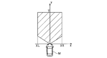
- FIG. 2 is a diagram for explaining an operation region
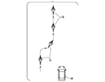
- FIG. 3 is a diagram illustrating an example in which an object interrupts the course of a vehicle.
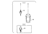
- 4A and 4B are diagrams showing the relative angle and the shape of the object when the relative angle is 0 °
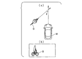
- 5A and 5B are diagrams showing the relative angle and the shape of the object when the relative angle is 45 °
- 6A and 6B are diagrams showing the relative angle and the shape of the object when the relative angle is 90 °.
- FIG. 1 is a block diagram showing the configuration of the object detection device of the present embodiment.
- FIG. 2 is a diagram for explaining an operation region
- FIG. 3 is a diagram illustrating an example in which an object interrupts the course of a vehicle.
- 4A and 4B are diagrams showing the relative angle and the shape of the object when the relative angle is 0 °
- 5A and 5B are diagrams showing the relative angle and
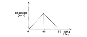
- FIG. 7 is a diagram showing the relationship between the upper limit value of the lateral speed and the relative angle
- FIG. 8 is a flowchart showing the processing executed by the object detection device
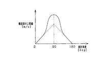
- FIG. 9 is another example of the relationship between the upper limit value of the lateral speed and the relative angle
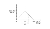
- FIG. 10 is another example of the relationship between the upper limit value of the lateral speed and the relative angle.
- the object detection device is mounted on a vehicle, detects an object existing around the front of the vehicle in the traveling direction, and controls to avoid collision with the object or reduce collision damage. Functions as a PCS system to perform.
- an object detection apparatus 10 is a computer including a CPU (Central Processing Unit), a ROM (Read Only Memory), a RAM (Random Access Memory), an I / O (Input / Output), and the like.
- these functions are realized by the CPU executing a program installed in the ROM.
- the object detection device 10 is connected to a measurement device 21 and an imaging device 22 as sensor devices for inputting various types of detection information.
- the measuring device 21 is, for example, a known millimeter wave radar that uses a millimeter wave band high frequency signal as a transmission wave.
- the measuring device 21 is provided at the front end portion of the vehicle, detects an object in a region that falls within a predetermined detection angle, and detects the position of the object within the detection range.
- an exploration wave is transmitted to an object at a predetermined period, and reflected waves from the object are received by a plurality of antennas.
- the distance to the object is calculated from the transmission time of the exploration wave and the reception time of the reflected wave.
- the relative velocity is calculated from the frequency of the reflected wave reflected by the object, which has changed due to the Doppler effect.
- the azimuth of the object is calculated from the phase difference of the reflected waves received by the plurality of antennas. If the position and orientation of the object can be calculated, the relative position of the object with respect to the vehicle can be specified. Note that the measurement device 21 performs transmission of the exploration wave, reception of the reflected wave, calculation of the reflection position and relative velocity at predetermined intervals, and the object detection device 10 using the calculated reflection position and relative velocity as the first detection information. Send to.
- the imaging device 22 is a monocular imaging device such as a CCD (Charged-Coupled Device) camera, a CMOS (Complementary Metal-Oxide Semiconductor) image sensor, or a near-infrared camera.
- the imaging device 22 is attached to a predetermined height in the center of the vehicle in the vehicle width direction, and images an area that extends in a predetermined angle range toward the front of the vehicle from an overhead viewpoint.
- the imaging device 22 extracts feature points indicating the presence of an object in the captured image. Specifically, edge points are extracted based on the luminance information of the captured image, and Hough transform is performed on the extracted edge points.
- the imaging device 22 performs imaging and feature point extraction at the same or different control period as the measurement device 21 and transmits the feature point extraction result to the object detection device 10 as second detection information.
- the vehicle includes an alarm device 31 and a brake device 32 as a safety device that is driven by a control command from the object detection device 10.
- the alarm device 31 is a speaker or a display installed in the passenger compartment of the vehicle.
- an alarm sound or a warning message is output according to a control command from the object detection device 10 to reduce the risk of collision to the driver. Inform.
- the brake device 32 is a braking device that brakes the vehicle.
- the object detection device 10 determines that the possibility of collision with an obstacle has increased, the object detection device 10 operates according to a control command from the object detection device 10. Specifically, the braking force with respect to the brake operation by the driver is increased (brake assist function), or automatic braking is performed if the driver does not perform the brake operation (automatic brake function).
- the information acquisition unit 11 acquires first detection information from the measurement device 21 and acquires second detection information from the imaging device 22. Then, the first position, which is a position obtained from the first detection information, and the second position, which is a feature point obtained from the second detection information, are associated with each other as being based on the same object. .
- the second position exists in the vicinity of the first position, there is a high possibility that an object actually exists in the first position.
- a state in which the position of the object can be accurately acquired by the measurement device 21 and the imaging device 22 is referred to as a fusion state.
- the detection history is referred to and it is determined whether or not the object continues to be in the fusion state.
- the detection history is referred to, and the object is handled as being present at the past position for a predetermined period.
- the object determined to be in this fusion state For the object determined to be in this fusion state, pattern matching using a pattern prepared in advance is performed on the second detection information. Then, the type is associated with the object.
- examples of the types of objects include automobiles, motorcycles, bicycles, pedestrians, and various road structures. A motorcycle and a bicycle may be combined into a motorcycle.
- the information acquisition unit 11 associates a relative position and a relative speed with respect to the vehicle for each object.
- a relative position a horizontal position indicating a relative distance in a direction orthogonal to the traveling direction of the vehicle and a vertical position that is a relative position in the traveling direction of the vehicle are obtained.
- a lateral speed that is a relative speed in a direction orthogonal to the traveling direction of the vehicle and a vertical speed that is a relative speed in the traveling direction of the vehicle are calculated.
- the direction orthogonal to the traveling direction of the vehicle can be referred to as a first direction
- the traveling direction of the vehicle can be referred to as a second direction. Since it can be said that the lateral velocity is a value indicating information related to the object, it can be referred to as an object velocity value, and the information acquisition unit 11 can be referred to as a velocity acquisition unit when acquiring the lateral velocity.
- the collision time calculation unit 12 calculates a collision prediction time which is a time until the vertical position of the object indicating the relative distance between the vehicle and the object becomes zero. Specifically, the vertical position of the object is divided by the vertical speed, which is the relative speed between the vehicle and the object, and the obtained time is set as the collision prediction time. At this time, when the vertical velocity is zero or when the vertical velocity takes a negative value (when the vehicle and the object move away from each other), the vertical position is not contracted, so the collision prediction time is not calculated. In calculating the collision prediction time, the collision prediction time may be calculated by using relative acceleration in addition to the relative distance and the relative speed and assuming that the object performs an equal acceleration motion with respect to the vehicle.
- the collision prediction time is calculated.
- the region setting unit 13 sets an operation region having a predetermined width in the lateral direction orthogonal to the traveling direction of the vehicle.
- This operation area is an area for determining whether or not the lateral position of the object is a position where the safety device should be operated. That is, if the lateral position of the object is within the operation region, it is determined that one condition for operating the safety device is satisfied.
- the width of the operation region is set larger as the lateral speed of the object is larger. This is because even if the object is not positioned in the course of the vehicle, the higher the lateral velocity of the object, the higher the possibility that the object will enter the course of the vehicle, and the possibility that the driver can recognize the object. This is because it is necessary to make the safety device easy to operate because of lowering.
- the width of the operating region may be different for each function of the safety device, or may be the same.
- the width of the operation area of the alarm device 31 is set to be the largest. This is because the object detection device 10 can avoid the collision without issuing a control command to the brake device 32 if the driver recognizes the danger of the collision by the warning device 31 and performs an operation to avoid the collision.
- the operation timing setting unit 14 sets the operation timing of the safety device. This operation timing is compared with the above-described collision prediction time. Then, when the position of the object is within the operation region and the predicted collision time is less than the operation timing, the safety device operates. That is, it can be said that the greater the operation timing is set, the more the safety device operates even when the predicted collision time is longer, and the safety device is operated earlier.
- This operation timing is set to a different value for each safety device function. Specifically, the operation timing of the alarm device 31 is set as the largest value. This is because the object detection device 10 can avoid the collision without issuing a control command to the brake device 32 if the driver notices the danger of the collision by the warning device 31 and depresses the brake pedal. Note that the operation timing of the brake device 32 is provided separately for the brake assist function and the automatic brake function. These operation timings may be the same value or different ones.
- the traveling direction of the vehicle M is the vertical axis (y axis), and the direction orthogonal to the vertical axis is the horizontal axis (x axis).
- the working area has a predetermined width in the x-axis direction, and the right width XR and the left width XL that indicate the width in the left-right direction of the working area are values determined in advance for each type of object.
- T which is the operation timing, is determined in the y-axis direction, and the value obtained by multiplying the operation timing by the relative speed (vertical speed) between the vehicle M and the object indicates the position. Corresponds to the value of the operation timing T.
- the operation timing T is also set in advance for each type of object.
- region is provided along the shape of the road where the vehicle M drive
- the operation region set by the region setting unit 13 and the operation timing set by the operation timing setting unit 14 are input to the operation determination unit 15.
- the operation determination unit 15 determines whether or not the lateral position of the object is within the operation region, and determines that one condition for operating the safety device is satisfied if the lateral position of the object is within the operation region. Similarly, it is determined whether the predicted collision time is equal to or shorter than the operation timing. If the predicted collision time is equal to or lower than the operation timing, it is determined that one condition for operating the safety device is satisfied. If the operation determination unit 15 determines that all conditions for operating the safety device are satisfied, an operation command is transmitted to the safety device, and the corresponding function of the safety device is executed.
- an upper limit value for the lateral speed of the object is provided by the angle acquisition unit 16 and the upper limit setting unit 17 included in the object detection device 10, If the detected lateral speed is greater than the upper limit value, processing for limiting the lateral speed value to the upper limit value is performed.
- the angle acquisition unit 16 acquires the relative angle of the moving direction of the object with respect to the moving direction of the vehicle as angle information based on the image of the object acquired from the imaging device 22. Specifically, one or a plurality of template images are stored in advance for each angle (posture angle) representing the posture of the object with respect to the vehicle M. Then, template matching between the template image and the object image is performed, and the posture angle associated with the template image having the highest similarity is set as a relative angle between the moving direction of the vehicle M and the moving direction of the object. Note that the value of the relative angle can be said to be a relationship indicating an angle.
- the traveling direction of the vehicle M and the traveling direction of the object B are the same, the traveling direction does not intersect, but the relative angle ⁇ is defined as 0 °.
- the image of the object B acquired from the imaging device 22 is an image of the object B taken from behind as shown in FIG.
- FIG. 5A shows an example in which the object B travels obliquely with respect to the moving direction of the vehicle M, and the relative angle ⁇ is 45 °.
- the image of the object B acquired from the imaging device 22 is an image of the object B taken obliquely from the rear as shown in FIG.
- FIG. 6A shows an example in which the object B moves so as to travel orthogonally to the moving direction of the vehicle, and the relative angle ⁇ is 90 °.
- the image of the object B acquired from the imaging device 22 is an image of the object B taken from the side as shown in FIG.
- the captured images differ depending on the relative angle between the traveling direction of the vehicle M and the traveling direction of the object B. It becomes. Using this, the relative angle is obtained by template matching.
- the template image may be provided for a person driving the bicycle, may be provided for the bicycle, or the person and the bicycle may be combined into a single template image. Moreover, the template image is provided for every predetermined angle. At this time, the relative angle intervals at which the template images are provided may be equal intervals, or may not be equal intervals. In this way, a template image is provided for each predetermined angle, and the template image is associated with the relative angle. For example, if the actual relative angle is 35 °, the image of the object B has the highest degree of similarity to the 30 ° template image. There is a high possibility that it will become large, and it is most likely that the relative angle will be determined to be 30 °.
- the upper limit setting unit 17 sets the upper limit value of the lateral speed based on the relative angle.
- the relationship between the upper limit value of the lateral velocity and the relative angle is shown in FIG.
- the relative angle when the traveling direction of the vehicle M and the traveling direction of the object B are orthogonal to each other is set to 90 °, and the traveling direction of the vehicle M and the traveling direction of the object B are the same direction.
- the relative angle is defined as 0 °, and the relative angle when the traveling direction of the vehicle M and the traveling direction of the object B are opposite is defined as 180 °.
- the lateral speed of the object B becomes maximum when the relative angle is 90 °, and decreases as the relative angle approaches 0 ° and approaches 180 °. Thus, it is zero when the relative angle is 0 ° and when the relative angle is 180 °.
- the upper limit of the speed that can be taken on the road is set as a maximum speed based on laws and empirical rules, and the maximum speed is the lateral speed when the relative angle is 90 °.
- the upper limit is set to a value of about 10 m / s, for example.
- a table in which the value of the relative angle and the value of the lateral velocity are associated with each other may be stored.
- the upper limit value of the lateral velocity of the object is obtained by the upper limit setting unit 17, the upper limit value is output to the region setting unit 13. If the lateral speed acquired from the information acquisition unit 11 is larger than the upper limit value, the area setting unit 13 sets the operating area using the lateral speed as the upper limit value. Further, if the lateral speed is equal to or lower than the upper limit value, the operation region is set using the lateral speed value as it is.
- An object detection method which is a series of processing executed by the object detection apparatus 10 configured as described above, will be described with reference to the flowchart of FIG.
- the flowchart shown in FIG. 8 is repeatedly executed every predetermined control cycle.
- the information acquisition unit 11 acquires detection information from the measurement device 21 and the imaging device 22, performs object recognition processing (S101), calculates the position of each object (S102), and calculates the vertical speed and the horizontal speed. Calculation is performed (S103). Then, based on the position and the vertical velocity, the collision time calculation unit 12 calculates the collision prediction time (S104). Subsequently, based on the image acquired from the imaging device 22, the angle acquisition unit 16 acquires a relative angle of the traveling direction of the object with respect to the traveling direction of the vehicle (S ⁇ b> 105), and the upper limit setting unit 17 determines the horizontal angle based on the relative angle. The upper limit value of speed is acquired (S106).
- the upper limit value of the lateral speed it is determined whether or not the lateral speed obtained from the measurement result of the measuring device 21 is larger than the upper limit value (S107). That is, it is determined whether or not the measurement result of the measurement device 21 is a value deviating from the lateral speed that can actually be taken. If the lateral speed is greater than the upper limit value (S107: YES), the lateral speed value is set as the upper limit value (S108). On the other hand, if the lateral speed is less than or equal to the upper limit value (S107: NO), the lateral speed is not deviated from the value that can actually be taken, and it can be said that it is detected correctly or with a small error. Value shall be used. If the value of the lateral speed is obtained in this way, the operation region is calculated based on the lateral speed (S109), and the operation timing is calculated (S110).
- the operation region is set as described above, it is determined whether or not the position of the object is within the operation region (S111).
- the position of the object is within the operation region (S111: YES)
- it is subsequently determined whether or not the predicted collision time is less than the operation timing (S112). . If the predicted collision time is equal to or shorter than the operation timing (S112: YES), since all conditions for operating the safety device are satisfied, the safety device is operated (S113), and the series of processes is terminated.
- the object detection device 10 has the following effects.
- the measuring device 21 Since the upper limit value is set based on the imaging result of the imaging device 22 for the lateral velocity acquired based on the measurement result of the measuring device 21, the measuring device 21 that easily causes a numerical detection error in the lateral direction is imaged. It can be supplemented by the function of the device 22.
- the speed can be limited to an upper limit value or less. Therefore, it is possible to suppress erroneous detection of the lateral speed with higher accuracy.
- the maximum is set when the relative angle is 90 °, and the relative angle is set so as to gradually decrease linearly toward each of 0 ° and 180 °.
- the relationship between the upper limit value of the lateral speed and the relative angle is not limited to that shown in the embodiment.
- the upper limit value of the lateral speed may be changed stepwise.
- the upper limit value of the lateral speed is the maximum when the relative angle is 90 °, and the relative angle is 0 ° and 180 °. It is good also based on the sine wave which makes 0 into. Other setting methods may be adopted.
- the upper limit value of the lateral speed is set to 0 when the relative angle is 0 ° and when the relative angle is 180 °, but may be a value larger than 0.
- the actual relative angle is 0. It is a value near ° or 0 °. Therefore, a value larger than 0 is often detected as the lateral speed.
- the object detection apparatus 10 excludes a value that is close to the actual lateral speed when the value that deviates from the actual value is detected as the lateral speed value. There is no. Therefore, as described above, the upper limit value of the lateral velocity may be set to a value larger than 0 when the relative angle is 0 ° and when the relative angle is 180 °.
- the maximum value is set at 90 °, and the upper limit value is reduced by the same amount of change as when approaching 0 ° and approaching 180 °.
- the amount of change need not be equal.
- the erroneous detection of the lateral velocity of the object is particularly problematic when the object B interrupts the course of the vehicle M as shown in FIG. 3.
- the traveling direction of the vehicle M and the object B The relative angle with respect to the traveling direction is a value closer to 0 ° than 90 °. Therefore, the relationship between the relative angle and the upper limit value of the lateral speed may be as shown in FIG. That is, in the range where the relative angle is close to 0 °, it is set as in the embodiment, and when the lateral speed is erroneously detected, the lateral speed is easily set as the upper limit value, and in the range where the relative angle is close to 90 °.
- the upper limit value may be set larger than the maximum speed to suppress the situation where the lateral speed becomes larger than the maximum speed. Further, as shown in FIG. 10, the upper limit value of the lateral speed may not be provided for the predetermined range ⁇ around 90 °. 9 and 10, the relationship between the relative angle and the upper limit value of the lateral velocity in the embodiment is indicated by a broken line.
- the relative angle when the moving direction of the vehicle and the moving direction of the object are orthogonal is defined as 90 °, but how to define the value of the angle is arbitrary.
- the relative angle when the moving direction of the vehicle and the moving direction of the object are orthogonal may be defined as 0 °.
- the relationship between the upper limit value of the lateral speed and the relative angle is stored in advance in the storage unit for each type of object, and the relative angle is calculated from the storage unit based on the detected type and relative angle of the object.
- the value is to be read.
- the upper limit value of the lateral speed may be set based on the speed of the object in the traveling direction.
- the width of the operation region is set using the lateral speed.
- the higher the lateral velocity of the object the higher the possibility that the object will enter the vehicle path, and the higher the possibility that the driver cannot recognize the object. Therefore, the operation timing of the safety device may be set larger as the lateral speed is larger, and the safety device may be operated even when the vertical distance is large.
- the relative angle between the traveling direction of the vehicle and the traveling direction of the object is obtained between 0 ° and 180 °.
- the traveling direction of the object is away from the lateral direction. It is good also as what calculates
- the relative angle between the traveling direction of the vehicle and the traveling direction of the object is obtained based on the image acquired by the imaging device 22, but can be obtained by other methods.
- the traveling direction may be obtained from the history of the position of the object.
- the relative angle of the traveling direction of the object with respect to the traveling direction of the vehicle is obtained, but acquisition of the relative angle is not an essential configuration. That is, it is possible to associate the upper limit value of the lateral velocity instead of the relative angle with the template image used when performing template matching, and acquire the upper limit value of the lateral velocity without acquiring the relative angle. Also in this case, since the upper limit value of the lateral speed is acquired based on the relationship between the traveling direction of the vehicle and the traveling direction of the object, the angle acquisition unit 16 can be rephrased as a relationship acquisition unit.
- the speed of the object in the direction orthogonal to the traveling direction of the vehicle is the lateral speed
- the upper limit value of the lateral speed is determined by the angle formed by the traveling direction of the vehicle and the traveling direction of the object.
- the upper limit of the lateral speed is determined by the lateral speed, which is the speed of the object in a direction perpendicular to the predetermined direction of the vehicle, not limited to the traveling direction of the vehicle, and the angle between the predetermined direction of the vehicle and the traveling direction of the object. May be.
- the vehicle may be moving or may not be moving.
- a bicycle is cited as an example of an object, but the present invention can be similarly applied to a moving body around the vehicle, such as a pedestrian, a motorcycle, and an automobile.
- the width of the operation region of the safety device is set using the lateral speed of the object, but the use of the lateral speed is not limited to this.
- the function of the object detection device 10 according to the embodiment may be adopted in realizing the function of causing the vehicle to follow the other vehicle traveling forward in the traveling direction.
- the upper limit value is set with the lateral velocity of the object as the object velocity value, and the width of the region is set using the lateral velocity.
- the lateral acceleration that is the lateral acceleration instead of the lateral velocity of the object is acquired as the object velocity value, and an upper limit value is set for the lateral acceleration, and the width of the region is set using the lateral acceleration.
- the upper limit value when the relative angle is 90 ° may be the maximum acceleration.
- both the lateral velocity and the lateral acceleration of the object may be acquired as the object velocity values, and an upper limit value may be set for each of the lateral velocity and the lateral acceleration.
- the object detection device 10 is mounted on the vehicle, but the mounting target is not limited to the vehicle, and can be mounted on various moving objects. Further, the object to be mounted on the object detection apparatus 10 is not limited to a moving body, and may be a stationary object. In this case, it can be used as a device for monitoring the moving direction and moving speed of an object around the mounting target.
- the present disclosure has been described with reference to the embodiments, it is understood that the present disclosure is not limited to the embodiments and structures. The present disclosure includes various modifications and modifications within the equivalent range. In addition, various combinations and forms, as well as other combinations and forms including only one element, more or less, are within the scope and spirit of the present disclosure.
Landscapes
- Engineering & Computer Science (AREA)
- Radar, Positioning & Navigation (AREA)
- Remote Sensing (AREA)
- Physics & Mathematics (AREA)
- General Physics & Mathematics (AREA)
- Mechanical Engineering (AREA)
- Transportation (AREA)
- Computer Networks & Wireless Communication (AREA)
- Automation & Control Theory (AREA)
- Theoretical Computer Science (AREA)
- Computer Vision & Pattern Recognition (AREA)
- Multimedia (AREA)
- Electromagnetism (AREA)
- Artificial Intelligence (AREA)
- Health & Medical Sciences (AREA)
- Evolutionary Computation (AREA)
- General Health & Medical Sciences (AREA)
- Medical Informatics (AREA)
- Software Systems (AREA)
- Computing Systems (AREA)
- Databases & Information Systems (AREA)
- Mathematical Physics (AREA)
- Human Computer Interaction (AREA)
- Chemical & Material Sciences (AREA)
- Combustion & Propulsion (AREA)
- Traffic Control Systems (AREA)
- Control Of Driving Devices And Active Controlling Of Vehicle (AREA)
Priority Applications (1)
| Application Number | Priority Date | Filing Date | Title |
|---|---|---|---|
| US16/062,522 US10960877B2 (en) | 2015-12-17 | 2016-11-28 | Object detection device and object detection method |
Applications Claiming Priority (2)
| Application Number | Priority Date | Filing Date | Title |
|---|---|---|---|
| JP2015-246691 | 2015-12-17 | ||
| JP2015246691A JP6477453B2 (ja) | 2015-12-17 | 2015-12-17 | 物体検知装置、物体検知方法 |
Publications (1)
| Publication Number | Publication Date |
|---|---|
| WO2017104387A1 true WO2017104387A1 (ja) | 2017-06-22 |
Family
ID=59056257
Family Applications (1)
| Application Number | Title | Priority Date | Filing Date |
|---|---|---|---|
| PCT/JP2016/085097 Ceased WO2017104387A1 (ja) | 2015-12-17 | 2016-11-28 | 物体検知装置及び物体検知方法 |
Country Status (3)
| Country | Link |
|---|---|
| US (1) | US10960877B2 (enExample) |
| JP (1) | JP6477453B2 (enExample) |
| WO (1) | WO2017104387A1 (enExample) |
Cited By (2)
| Publication number | Priority date | Publication date | Assignee | Title |
|---|---|---|---|---|
| EP3770804A1 (de) * | 2019-07-24 | 2021-01-27 | Jungheinrich Aktiengesellschaft | Flurförderzeug mit einer objekterkennung |
| WO2022034775A1 (ja) * | 2020-08-11 | 2022-02-17 | 株式会社デンソー | 衝突判定装置、衝突判定方法および衝突回避システム |
Families Citing this family (10)
| Publication number | Priority date | Publication date | Assignee | Title |
|---|---|---|---|---|
| JP6729282B2 (ja) * | 2016-10-18 | 2020-07-22 | 株式会社デンソー | 車両制御装置 |
| DE102017205030A1 (de) * | 2017-03-24 | 2018-09-27 | Volkswagen Aktiengesellschaft | Fahrassistenzsystembasiertes Lenkunterstützungsverfahren, Lenkunterstützungssystem und Fahrzeug |
| JP6806250B2 (ja) * | 2017-06-20 | 2021-01-06 | 日本電気株式会社 | 位置測定装置、位置測定方法およびプログラム |
| KR102054926B1 (ko) * | 2018-02-27 | 2019-12-12 | 주식회사 만도 | Free Space 신호 기반 근거리 컷인 차량 검출 시스템 및 방법 |
| CN111497837B (zh) * | 2019-01-29 | 2022-07-19 | 宇通客车股份有限公司 | 一种基于前向感知的车辆控制方法及系统 |
| JP7328863B2 (ja) * | 2019-10-11 | 2023-08-17 | 株式会社デンソー | 制御装置 |
| JP7265971B2 (ja) * | 2019-10-11 | 2023-04-27 | 株式会社デンソー | 制御装置 |
| CN111409631B (zh) * | 2020-04-10 | 2022-01-11 | 新石器慧通(北京)科技有限公司 | 一种车辆行驶的控制方法、装置、车辆及存储介质 |
| JP2022099973A (ja) * | 2020-12-23 | 2022-07-05 | ロベルト・ボッシュ・ゲゼルシャフト・ミト・ベシュレンクテル・ハフツング | ライダー支援システムの制御装置及び制御方法 |
| KR20230055722A (ko) * | 2021-10-19 | 2023-04-26 | 현대모비스 주식회사 | 차량의 타겟 감지 시스템 및 방법 |
Citations (2)
| Publication number | Priority date | Publication date | Assignee | Title |
|---|---|---|---|---|
| JP2012048460A (ja) * | 2010-08-26 | 2012-03-08 | Denso Corp | 走行支援装置 |
| JP2012513651A (ja) * | 2008-12-23 | 2012-06-14 | コンテイネンタル・セイフテイ・エンジニヤリング・インターナシヨナル・ゲゼルシヤフト・ミツト・ベシユレンクテル・ハフツング | 車両と生物との衝突確率を求める方法 |
Family Cites Families (7)
| Publication number | Priority date | Publication date | Assignee | Title |
|---|---|---|---|---|
| DE10235414A1 (de) * | 2002-08-02 | 2004-02-12 | Robert Bosch Gmbh | Verfahren und Vorrichtung zur Ermittlung des Bevorstehens einer unausweichbaren Kollision |
| JP2007534041A (ja) | 2003-09-23 | 2007-11-22 | ダイムラークライスラー・アクチェンゲゼルシャフト | 車両用の車線変更運転認識方法及び装置 |
| JP5111321B2 (ja) * | 2008-10-06 | 2013-01-09 | 株式会社豊田中央研究所 | 瞼尤度演算装置、及びプログラム |
| JP5482672B2 (ja) | 2011-01-12 | 2014-05-07 | 株式会社デンソーアイティーラボラトリ | 移動物体検出装置 |
| JP6175846B2 (ja) * | 2013-03-27 | 2017-08-09 | 富士通株式会社 | 車両追跡プログラム、サーバ装置および車両追跡方法 |
| JP5905846B2 (ja) * | 2013-03-29 | 2016-04-20 | 株式会社日本自動車部品総合研究所 | 横断判定装置およびプログラム |
| JP6397934B2 (ja) * | 2014-12-19 | 2018-09-26 | 株式会社日立製作所 | 走行制御装置 |
-
2015
- 2015-12-17 JP JP2015246691A patent/JP6477453B2/ja active Active
-
2016
- 2016-11-28 WO PCT/JP2016/085097 patent/WO2017104387A1/ja not_active Ceased
- 2016-11-28 US US16/062,522 patent/US10960877B2/en active Active
Patent Citations (2)
| Publication number | Priority date | Publication date | Assignee | Title |
|---|---|---|---|---|
| JP2012513651A (ja) * | 2008-12-23 | 2012-06-14 | コンテイネンタル・セイフテイ・エンジニヤリング・インターナシヨナル・ゲゼルシヤフト・ミツト・ベシユレンクテル・ハフツング | 車両と生物との衝突確率を求める方法 |
| JP2012048460A (ja) * | 2010-08-26 | 2012-03-08 | Denso Corp | 走行支援装置 |
Cited By (3)
| Publication number | Priority date | Publication date | Assignee | Title |
|---|---|---|---|---|
| EP3770804A1 (de) * | 2019-07-24 | 2021-01-27 | Jungheinrich Aktiengesellschaft | Flurförderzeug mit einer objekterkennung |
| WO2022034775A1 (ja) * | 2020-08-11 | 2022-02-17 | 株式会社デンソー | 衝突判定装置、衝突判定方法および衝突回避システム |
| JP2022032109A (ja) * | 2020-08-11 | 2022-02-25 | 株式会社デンソー | 衝突判定装置、衝突判定方法および衝突回避システム |
Also Published As
| Publication number | Publication date |
|---|---|
| JP6477453B2 (ja) | 2019-03-06 |
| JP2017111682A (ja) | 2017-06-22 |
| US20180370531A1 (en) | 2018-12-27 |
| US10960877B2 (en) | 2021-03-30 |
Similar Documents
| Publication | Publication Date | Title |
|---|---|---|
| JP6477453B2 (ja) | 物体検知装置、物体検知方法 | |
| JP6561584B2 (ja) | 車両制御装置、及び車両制御方法 | |
| JP6432447B2 (ja) | 車両制御装置、及び車両制御方法 | |
| US10559205B2 (en) | Object existence determination method and apparatus | |
| US9470790B2 (en) | Collision determination device and collision determination method | |
| JP6504042B2 (ja) | 制御装置、制御方法 | |
| JP6451623B2 (ja) | 走行支援装置 | |
| JP6493196B2 (ja) | 制御装置、制御方法 | |
| JP6432482B2 (ja) | 車両制御装置、車両制御方法 | |
| JP6380232B2 (ja) | 物体検出装置、及び物体検出方法 | |
| JP2017117344A (ja) | 走行支援装置 | |
| CN108137007B (zh) | 车辆控制装置以及车辆控制方法 | |
| JP6432538B2 (ja) | 衝突予測装置 | |
| JP2019052920A (ja) | 物体検出装置、物体検出方法及び車両制御システム | |
| WO2017171082A1 (ja) | 車両制御装置、車両制御方法 | |
| WO2016186124A1 (ja) | 車両制御方法及び装置 | |
| WO2017145845A1 (ja) | 衝突予測装置 | |
| WO2017154471A1 (ja) | 横断判定装置 |
Legal Events
| Date | Code | Title | Description |
|---|---|---|---|
| 121 | Ep: the epo has been informed by wipo that ep was designated in this application |
Ref document number: 16875371 Country of ref document: EP Kind code of ref document: A1 |
|
| NENP | Non-entry into the national phase |
Ref country code: DE |
|
| 122 | Ep: pct application non-entry in european phase |
Ref document number: 16875371 Country of ref document: EP Kind code of ref document: A1 |