WO2017098874A1 - リレー - Google Patents
リレー Download PDFInfo
- Publication number
- WO2017098874A1 WO2017098874A1 PCT/JP2016/083974 JP2016083974W WO2017098874A1 WO 2017098874 A1 WO2017098874 A1 WO 2017098874A1 JP 2016083974 W JP2016083974 W JP 2016083974W WO 2017098874 A1 WO2017098874 A1 WO 2017098874A1
- Authority
- WO
- WIPO (PCT)
- Prior art keywords
- contact
- low
- rigidity
- pressing member
- contact piece
- Prior art date
- Legal status (The legal status is an assumption and is not a legal conclusion. Google has not performed a legal analysis and makes no representation as to the accuracy of the status listed.)
- Ceased
Links
Images



Classifications
-
- H—ELECTRICITY
- H01—ELECTRIC ELEMENTS
- H01H—ELECTRIC SWITCHES; RELAYS; SELECTORS; EMERGENCY PROTECTIVE DEVICES
- H01H51/00—Electromagnetic relays
- H01H51/02—Non-polarised relays
- H01H51/04—Non-polarised relays with single armature; with single set of ganged armatures
- H01H51/06—Armature is movable between two limit positions of rest and is moved in one direction due to energisation of an electromagnet and after the electromagnet is de-energised is returned by energy stored during the movement in the first direction, e.g. by using a spring, by using a permanent magnet, by gravity
- H01H51/08—Contacts alternately opened and closed by successive cycles of energisation and de-energisation of the electromagnet, e.g. by use of a ratchet
-
- H—ELECTRICITY
- H01—ELECTRIC ELEMENTS
- H01H—ELECTRIC SWITCHES; RELAYS; SELECTORS; EMERGENCY PROTECTIVE DEVICES
- H01H50/00—Details of electromagnetic relays
- H01H50/54—Contact arrangements
- H01H50/56—Contact spring sets
-
- H—ELECTRICITY
- H01—ELECTRIC ELEMENTS
- H01H—ELECTRIC SWITCHES; RELAYS; SELECTORS; EMERGENCY PROTECTIVE DEVICES
- H01H50/00—Details of electromagnetic relays
- H01H50/64—Driving arrangements between movable part of magnetic circuit and contact
-
- H—ELECTRICITY
- H01—ELECTRIC ELEMENTS
- H01H—ELECTRIC SWITCHES; RELAYS; SELECTORS; EMERGENCY PROTECTIVE DEVICES
- H01H51/00—Electromagnetic relays
- H01H51/02—Non-polarised relays
- H01H51/04—Non-polarised relays with single armature; with single set of ganged armatures
- H01H51/06—Armature is movable between two limit positions of rest and is moved in one direction due to energisation of an electromagnet and after the electromagnet is de-energised is returned by energy stored during the movement in the first direction, e.g. by using a spring, by using a permanent magnet, by gravity
- H01H51/08—Contacts alternately opened and closed by successive cycles of energisation and de-energisation of the electromagnet, e.g. by use of a ratchet
- H01H51/082—Contacts alternately opened and closed by successive cycles of energisation and de-energisation of the electromagnet, e.g. by use of a ratchet using rotating ratchet mechanism
- H01H51/084—Contacts alternately opened and closed by successive cycles of energisation and de-energisation of the electromagnet, e.g. by use of a ratchet using rotating ratchet mechanism with axial ratchet elements
-
- H—ELECTRICITY
- H01—ELECTRIC ELEMENTS
- H01H—ELECTRIC SWITCHES; RELAYS; SELECTORS; EMERGENCY PROTECTIVE DEVICES
- H01H50/00—Details of electromagnetic relays
- H01H50/16—Magnetic circuit arrangements
- H01H50/18—Movable parts of magnetic circuits, e.g. armature
- H01H50/20—Movable parts of magnetic circuits, e.g. armature movable inside coil and substantially lengthwise with respect to axis thereof; movable coaxially with respect to coil
-
- H—ELECTRICITY
- H01—ELECTRIC ELEMENTS
- H01H—ELECTRIC SWITCHES; RELAYS; SELECTORS; EMERGENCY PROTECTIVE DEVICES
- H01H50/00—Details of electromagnetic relays
- H01H50/64—Driving arrangements between movable part of magnetic circuit and contact
- H01H50/641—Driving arrangements between movable part of magnetic circuit and contact intermediate part performing a rectilinear movement
- H01H50/642—Driving arrangements between movable part of magnetic circuit and contact intermediate part performing a rectilinear movement intermediate part being generally a slide plate, e.g. a card
-
- H—ELECTRICITY
- H01—ELECTRIC ELEMENTS
- H01H—ELECTRIC SWITCHES; RELAYS; SELECTORS; EMERGENCY PROTECTIVE DEVICES
- H01H50/00—Details of electromagnetic relays
- H01H50/64—Driving arrangements between movable part of magnetic circuit and contact
- H01H50/643—Driving arrangements between movable part of magnetic circuit and contact intermediate part performing a rotating or pivoting movement
Definitions
- the present invention relates to a relay.
- contacts are opened and closed by moving one contact with respect to the other.
- the pressing member when a voltage is applied to the coil, the pressing member is driven by the magnetic force of the coil. Then, when the pressing member presses the contact piece, the movable contact attached to the contact piece moves to contact the fixed contact.
- the pressing member moves the movable contact by pressing and bending the contact piece. Therefore, when the rigidity of the contact piece increases, it is necessary to increase the force for driving the pressing member. As a result, there is a problem that the power consumption of the coil increases. In particular, when an actuator that uses an overshoot position that exceeds the on position is used when moving the pressing member from the off position to the on position, if the rigidity of the contact piece increases, the pressing member is moved to the overshoot position. In order to move it, a greater force is required. Therefore, the power consumption of the coil further increases.
- An object of the present invention is to suppress an increase in energy consumption in an actuator and to obtain a stable operation of a contact piece even when an actuator that moves a pressing member via an overshoot position is used in a relay. .
- the relay includes a first contact, a terminal, a second contact, a contact piece, a pressing member, and an actuator.
- the first contact is attached to the terminal.
- the second contact is disposed to face the first contact.
- a second contact is attached to the contact piece.
- the pressing member is provided to be movable between an off position and an on position. When the pressing member is in the off position, the first contact and the second contact are in a non-contact state. When the pressing member is in the on position, the pressing member presses the contact piece, so that the first contact and the second contact are in contact.
- the actuator moves the pressing member from the off position to the on position via an overshoot position exceeding the on position.
- a contact piece has a main-body part and a low-rigidity part whose rigidity is lower than a main-body part. The pressing member presses the low rigidity portion.
- the low rigidity portion can be bent with a small force by the pressing member pressing the low rigidity portion. Therefore, an increase in energy consumption at the actuator can be suppressed. Even if the rigidity of the terminal is high, the load on the contact piece caused by moving the pressing member to the overshoot position can be released because the low-rigidity portion bends. Thereby, the operation
- the low rigidity portion may be thinner than the main body portion. In this case, since the thickness of the low-rigidity portion is thin, the rigidity of the low-rigidity portion can be reduced.
- the contact piece may have a plurality of leaf springs stacked on each other. The number of leaf springs constituting the low rigidity portion may be smaller than the number of leaf springs constituting the main body portion. In this case, since the number of leaf springs constituting the low-rigidity portion is small, the rigidity of the low-rigidity portion can be reduced.
- the low-rigidity part may be located on the tip side of the contact piece with respect to the second contact. In this case, the low rigidity portion can be greatly bent with a small force.
- the width of the low rigidity portion may be smaller than the width of the main body portion. In this case, the rigidity of the low-rigidity part can be reduced by reducing the width of the low-rigidity part.
- the contact piece may have a slit provided between the low-rigidity part and the main body part. In this case, the slit can reduce the rigidity of the low rigidity portion.
- the low rigidity portion may include a first low rigidity portion and a second low rigidity portion.
- the first low-rigidity part and the second low-rigidity part may extend from the main body part in the longitudinal direction of the contact piece, and may be arranged apart from each other in the width direction of the contact piece. In this case, the load on the contact piece can be released by bending the first low-rigidity portion and the second low-rigidity portion.
- the main body may have a contact attachment portion to which the second contact is attached.
- the contact attachment portion may be disposed between the first low rigidity portion and the second low rigidity portion.
- the contact piece may have a first slit and a second slit.
- the first slit may be provided between the first low-rigidity part and the contact attachment part, and may extend in the longitudinal direction of the contact piece.
- the second slit may be provided between the second low-rigidity part and the contact attachment part, and may extend in the longitudinal direction of the contact piece. In this case, the first slit and the second slit can reduce the rigidity of the first low-rigidity portion and the second low-rigidity portion.
- the first slit and the second slit may extend to a position closer to the base end side of the contact piece than the second contact. Thereby, the rigidity of the first low-rigidity part and the second low-rigidity part can be further reduced.
- the low-rigidity part may further include a connecting part that connects the first low-rigidity part and the second low-rigidity part. Thereby, the twist of a 1st low-rigidity part and a 2nd low-rigidity part is suppressed, and, thereby, the shift
- the pressing member may press the connecting portion.
- the pressing member may press the first low rigidity portion and the second low rigidity portion.
- the pressing position of the low-rigidity portion by the pressing member may be located closer to the distal end side of the contact piece than the second contact.
- the low rigidity portion can be greatly bent with a small force.
- the actuator may further include a holding member that holds the pressing member in the on position by being engaged with the pressing member. In this case, the pressing member can be stably held at the on position without being affected by an impact or external magnetic force as compared with the case where the pressing member is held at the on position by magnetic force.
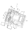
- FIG. 1 is a perspective view of a relay 1 according to the embodiment.
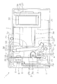
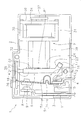
- 2 and 3 are plan views of the relay 1.
- FIG. 2 shows the relay 1 in the set state
- FIG. 3 shows the relay 1 in the reset state.
- the relay 1 according to the present embodiment is a latch type relay.
- the relay 1 includes a base 2, a fixed contact terminal 3, a movable contact terminal 4, a contact piece 5, a pressing member 6, and an actuator 7.
- the base 2 accommodates a fixed contact terminal 3, a movable contact terminal 4, a contact piece 5, a pressing member 6, and an actuator 7.
- One surface of the base 2 is open, and the opening of the base 2 is covered with a cover (not shown).
- the fixed contact terminal 3 is formed of a conductive material such as copper.
- a first contact 8 is attached to one end of the fixed contact terminal 3.
- the other end of the fixed contact terminal 3 protrudes from the base 2 to the outside.
- a first support groove 11 is provided inside the base 2, and the fixed contact terminal 3 is supported by the base 2 by being fitted into the first support groove 11.
- the movable contact terminal 4 is formed of a conductive material such as copper. As shown in FIG. 2, a support portion 12 is provided at one end of the movable contact terminal 4. The contact piece 5 is attached to the support portion 12. The other end of the movable contact terminal 4 protrudes from the base 2 to the outside. A second support groove 13 is provided inside the base 2, and the movable contact terminal 4 is supported by the base 2 by being fitted into the second support groove 13.
- the contact piece 5 is formed of a conductive material such as copper.
- the contact piece 5 is disposed to face the fixed contact terminal 3.
- the tip 14 of the contact piece 5 is pressed by the pressing member 6.
- the base end portion 15 of the contact piece 5 is attached to the support portion 12 of the movable contact terminal 4.
- the contact piece 5 is supported by the support portion 12.
- a second contact 9 is attached to the contact piece 5.
- the second contact 9 is disposed to face the first contact 8.
- the second contact 9 is located between the tip portion 14 and the support portion 12.
- the contact piece 5 has a curved portion 16.
- the bending portion 16 is located between the second contact 9 and the support portion 12.
- the second contact 9 is located between the distal end portion 14 and the bending portion 16.
- the curved portion 16 has a shape that bulges away from the fixed contact terminal 3.
- the curved portion 16 may have a shape that bulges in the direction toward the fixed contact terminal 3.
- the contact piece 5 has a plurality of leaf springs 5a and 5b.
- the contact piece 5 is formed by overlapping a plurality of leaf springs 5a and 5b.
- the second contact 9 is provided so as to be movable with respect to the first contact 8. Specifically, when the contact piece 5 is pressed by the pressing member 6, the contact piece 5 is elastically deformed and bent toward the fixed contact terminal 3. As a result, the second contact 9 moves toward the first contact 8. When the pressing to the contact piece 5 by the pressing member 6 is released, the contact piece 5 returns to the direction away from the fixed contact terminal 3 due to the elastic force of the contact piece 5. As a result, the second contact 9 is separated from the first contact 8. The second contact 9 may be separated from the first contact 8 when the contact piece 5 is pulled by the pressing member 6.
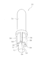
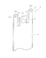
- FIG. 4 is a perspective view of the contact piece 5 according to the first embodiment.
- the contact piece 5 has a main body portion 71 and a low rigidity portion 72.
- a second contact 9 is attached to the main body 71.
- the main body portion 71 includes the bending portion 16 and the base end portion 15 described above.
- the low-rigidity portion 72 protrudes from the main body portion 71 toward the distal end side.
- the low-rigidity portion 72 is located on the tip side of the contact piece 5 with respect to the second contact 9.
- the low rigidity portion 72 includes the tip portion 14 described above. Therefore, the pressing member 6 presses the low rigidity portion 72.
- the pressing position of the low-rigidity portion 72 by the pressing member 6 is located closer to the distal end side of the contact piece 5 than the second contact 9.
- the number of leaf springs 5a constituting the low rigidity portion 72 is smaller than the number of leaf springs 5a and 5b constituting the main body portion 71. Accordingly, the low rigidity portion 72 is thinner than the main body portion 71.
- the width W1 of the low-rigidity portion 72 is smaller than the width W2 of the main body portion 71.
- the rigidity of the low-rigidity part 72 is lower than the rigidity of the main body part 71. That is, even when pressed with the same force, the displacement amount of the low-rigidity portion 72 is larger than the displacement amount of the main body portion 71. In other words, the low-rigidity portion 72 can obtain the same displacement amount with a pressing force smaller than the pressing force required by the main body portion 71.
- the number of leaf springs 5a and 5b constituting the main body 71 is two, and the number of leaf springs 5a constituting the low-rigidity portion 72 is one.
- the number of leaf springs 5a and 5b constituting the main body 71 may be more than two.
- the number of leaf springs 5a constituting the low rigidity portion 72 may be more than one.
- the pressing member 6 includes a first pressing member 33 and a second pressing member 38.
- the first pressing member 33 presses the second pressing member 38 by moving in the axial direction.
- the second pressing member 38 has a fulcrum 17 and a contact portion 18.
- the fulcrum 17 is rotatably supported by the base 2.
- the fulcrum 17 is located closer to the support portion 12 than the bending portion 16.
- the contact portion 18 is disposed to face the contact piece 5.
- the second pressing member 38 makes the contact portion 18 contact the contact piece 5 by rotating in the direction approaching the contact piece 5 around the fulcrum 17. Thereby, the contact part 18 presses the front-end
- the second pressing member 38 has a first movable part 21 and a second movable part 22.
- the first movable part 21 and the second movable part 22 are separate from each other.
- the first movable part 21 includes a fulcrum 17.
- the second movable portion 22 includes the contact portion 18 and extends from the first movable portion 21 toward the contact piece 5.
- the first movable portion 21 has a first portion 23 and a second portion 24.
- the first movable portion 21 has a shape bent between the first portion 23 and the second portion 24. Specifically, the first portion 23 extends obliquely from the fulcrum 17 toward the contact piece 5.
- the second portion 24 is disposed between the contact piece 5 and the actuator 7.
- the second movable portion 22 extends from the distal end of the first movable portion 21 toward the distal end portion 14 of the contact piece 5.
- the second movable part 22 is connected to the tip of the first movable part 21.
- the second movable portion 22 has an opening 25.
- the tip of the first movable part 21 is disposed in the opening 25 of the second movable part 22.
- the second movable part 22 has a recess 26.
- the distal end portion 14 of the contact piece 5 is disposed in the recess 26.
- the contact portion 18 described above is a part of the edge of the recess 26.
- the front end portion 14 of the contact piece 5 has a shape bent toward the contact portion 18.
- Actuator 7 moves the first pressing member 33 in the axial direction.
- the actuator 7 has a coil part 31 and a holding mechanism 32.
- the coil unit 31 includes a bobbin 34, a winding 35, a coil case 36, and an iron core 37.
- the winding 35 is wound around the bobbin 34.
- the winding 35 is connected to a coil terminal (not shown).
- the coil part 31 generates a magnetic force so that the iron core 37 arrange
- the holding mechanism 32 and the first pressing member 33 are disposed in the housing 39.
- the holding mechanism 32 transmits the operation of the iron core 37 to the first pressing member 33, thereby moving the first pressing member 33 to the on position shown in FIG. 2 and the off position shown in FIG.
- the holding mechanism 32 mechanically holds the first pressing member 33 between the on position and the off position in a state where no voltage is applied to the coil portion 31.
- the holding mechanism 32 will be described in detail later.
- the first pressing member 33 presses the second pressing member 38 by moving in the axial direction.
- the pressing position P ⁇ b> 1 where the first pressing member 33 presses the second pressing member 38 is located between the fulcrum 17 and the contact portion 18.
- the pressing position P ⁇ b> 1 is located closer to the second contact 9 than the bending portion 16.
- the pressing position P ⁇ b> 1 is located closer to the bending portion 16 than the second contact 9.
- the contact piece 5 bends in the direction toward the movable contact terminal 4.
- the first contact 8 and the second contact 9 come into contact, and the relay 1 is set.
- the first pressing member 33 returns from the on position to the off position, the first contact 8 and the second contact 9 are separated and the relay 1 returns to the reset state.
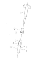
- FIG. 5 is a cross-sectional view showing the configuration of the holding mechanism 32.
- FIG. 6 is an exploded perspective view showing a part of the configuration of the holding mechanism 32.
- the holding mechanism 32 includes a lid portion 41, a holding member 42, and a pusher 43.
- the lid 41 is attached to the tip of the holding member 42.
- a through hole 44 is provided inside the lid portion 41 and the holding member 42.
- the first pressing member 33, the pusher 43, and the above-described iron core 37 are disposed so as to be movable in the axial direction in the through hole 44.
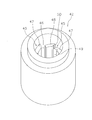
- FIG. 7 is a perspective view of the holding member 42.
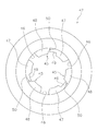
- FIG. 8 is a view of the holding member 42 as seen from the axial direction.
- the holding member 42 has a plurality of holding convex portions 45.
- the holding convex portion 45 protrudes from the inner peripheral surface of the holding member 42.
- the plurality of holding convex portions 45 are arranged at intervals in the circumferential direction of the holding member 42. Release grooves 46 extending in the axial direction are provided between the plurality of holding convex portions 45.
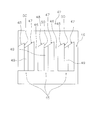
- FIG. 9 is a diagram in which the inner peripheral surface of the holding member 42 is developed on a plane.
- the holding convex portion 45 has a locking inclined surface 47 and a releasing inclined surface 48.
- a step portion is provided between the locking inclined surface 47 and the release inclined surface 48.
- the holding protrusion 45 is provided with a guide groove 49 extending in the axial direction.
- FIG. 10 is a perspective view of the pusher 43. As shown in FIG. 10, a plurality of guide convex portions 51 are provided on the outer peripheral surface of the pusher 43.
- the guide protrusions 51 are arranged at intervals in the circumferential direction of the pusher 43.
- the guide convex portions 51 are disposed in the guide groove 49 and the release groove 46 of the holding member 42, respectively.
- the guide protrusion 51 moves along the guide groove 49 and the release groove 46.
- a hole 52 and a plurality of inclined surfaces 53 are provided at one end of the pusher 43.
- the plurality of inclined surfaces 53 are arranged around the hole 52.
- One end of the pusher 43 is provided so as to be pressed by an iron core 37.
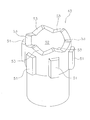
- FIG. 11 is a perspective view of the first pressing member 33.
- the first pressing member 33 includes a pressing portion 55, a locking portion 56, and a support shaft 57.
- the pressing portion 55 has a shaft shape.
- the tip of the pressing part 55 is curved.
- the locking part 56 has a plurality of locking projections 58.
- the plurality of locking projections 58 are arranged at intervals in the circumferential direction of the locking portion 56.
- the plurality of locking projections 58 are provided to be movable along the release groove 46 described above.
- FIG. 12 is a view showing the first pressing member 33 and the pusher 43.
- the plurality of inclined surfaces 59 of the locking portion 56 are arranged to face the plurality of inclined surfaces 53 of the pusher 43.
- the support shaft 57 protrudes from the locking portion 56.
- the support shaft 57 is disposed in the hole 52 of the pusher 43.
- FIG. 13 is a cross-sectional view showing the operating state of the actuator 7.
- the on position of the first pressing member 33 is indicated by “Pon”, and the off position is indicated by “Poff”.
- “Pov” indicates an overshoot position of the first pressing member 33 described later.
- 14 and 15 are diagrams showing the relationship between the inner peripheral surface of the holding member 42 and the locking projection 58 of the first pressing member 33 on a plane.
- the “off direction” means a direction from the on position Pon to the off position Poff.
- the “off direction” is the right side in FIG. 13 and the lower side in FIGS.
- the “on direction” means a direction from the off position Poff to the on position Pon.
- the “on direction” is the left side in FIG. 13 and the upper side in FIGS. 14 and 15.
- the first pressing member 33 is located at the off position Poff.
- the locking convex portion 58 of the first pressing member 33 is disposed in the release groove 46 of the holding member 42.
- a voltage is applied to the actuator 7
- an electromagnetic force in the ON direction is generated on the iron core 37 by the coil portion 31.
- the iron core 37 moves in the ON direction and presses the pusher 43.
- the pusher 43 presses the locking portion 56 in the ON direction.
- the latching convex part 58 moves to an ON direction along the cancellation
- the first pressing member 33 is further moved from the on position Pon to the overshoot position Pov in the on direction. Is located.
- the first pressing member 33 moves in the off direction by the elastic force of the contact piece 5.
- the locking projection 58 contacts the locking inclined surface 47 by moving in the off direction.
- the end of the locking projection 58 has an inclined surface 64 that is inclined in the same direction as the locking inclined surface 47. Therefore, when the locking portion 56 is further pressed in the off direction, the inclined surface 64 of the locking convex portion 58 slides along the locking inclined surface 47 (arrow A4). And the latching convex part 58 is latched by the latching inclined surface 47 and the step part 50, and stops.
- the first pressing member 33 is located at the on position Pon shown in FIG. As shown in FIG. 13C, even if the pusher 43 and the iron core 37 return in the off direction, the first pressing member 33 is turned off because the locking portion 56 is locked to the holding member 42. Does not move in the direction. Accordingly, the first pressing member 33 is held at the on position Pon against the elastic force of the contact piece 5.
- the locking projection 58 moves to a position facing the guide groove 49, the outer diameter of the locking projection 58 is larger than the inner diameter of the guide groove 49. Therefore, the locking projection 58 does not enter the guide groove 49 but is locked to the holding projection 45. Thereby, the movement to the OFF direction of the latching convex part 58 is controlled.
- FIG. 13C when a voltage is applied to the actuator 7 in a state where the first pressing member 33 is located at the on position Pon, the coil portion 31 turns on the iron core 37 in the on direction. Electromagnetic force is generated. As a result, the iron core 37 moves in the ON direction, and the pusher 43 presses the first pressing member 33 in the ON direction from the ON position Pon against the elastic force of the contact piece 5. Thereby, as shown to FIG. 15 (A), the latching convex part 58 moves to an ON direction (arrow A5).
- the locking projection 58 exceeds the stepped portion 50 of the holding member 42, the locking portion 56 rotates around the axis, as described above. Thereby, as shown in FIG. 15B, the locking projection 58 moves to a position facing the release inclined surface 48 (arrow A6). At this time, the first pressing member 33 is located at the overshoot position Pov shown in FIG. Next, when the voltage to the actuator 7 is released, the first pressing member 33 moves in the off direction by the elastic force of the contact piece 5. Thereby, the inclined surface 53 of the locking projection 58 slides along the release inclined surface 48 and moves to a position facing the release groove 46 as shown in FIG. Then, the locking projection 58 moves in the off direction along the release groove 46. Thereby, the latching
- the actuator 7 moves the first pressing member 33 from the off position Poff to the on position Pon via the overshoot position Pov.
- the actuator 7 moves the first pressing member 33 from the on position Pon to the off position Poff via the overshoot position Pov.
- the holding member 42 is switched between holding and releasing the first pressing member 33.
- the relay 1 has the following characteristics.
- the low rigidity portion 72 can be bent with a small force. Therefore, an increase in energy consumption at the actuator 7 can be suppressed.
- the thickness of the main body portion 71 can be made larger than the thickness of the low rigidity portion 72. Thereby, the electroconductivity of the contact piece 5 can be improved and the excessive temperature rise at the time of electricity supply can be suppressed.
- the thickness of the fixed contact terminal 3 is larger than the thickness of the main body 71. Therefore, the rigidity of the fixed contact terminal 3 is larger than the rigidity of the main body 71. However, even if the rigidity of the fixed contact terminal 3 is high, the load on the contact piece 5 due to the movement of the first pressing member 33 to the overshoot position Pov can be released because the low rigidity portion 72 is bent. Thereby, the operation
- the first pressing member 33 is held at the on position Pon when the locking portion 56 is locked to the holding member 42. That is, the first pressing member 33 is mechanically held at the on position Pon, not magnetic force. For this reason, even if the voltage of the coil 31 is eliminated, the relay 1 can be maintained in the set state. Further, when a voltage is applied to the coil 31 to release the set state, the pusher 43 rotates and the first pressing member 33 is held at the off position Poff. For this reason, even if the voltage of the coil 31 is eliminated, the relay 1 can be maintained in the reset state.
- the relay 1 every time a pulse signal is input to the actuator 7, the relay 1 is alternately switched between a set state and a reset state. If no signal is input, the state of the relay 1 is maintained as it is. Therefore, the state of the relay 1 can be maintained without maintaining the application of voltage to the actuator 7. Thereby, the power consumption of the relay 1 can be reduced. Further, since the control can be performed by the pulse signal, the control circuit of the actuator 7 can be easily configured.
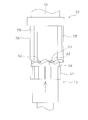
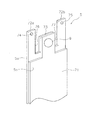
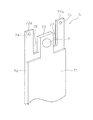
- FIG. 16 is a perspective view of the contact piece 5 according to the second embodiment.
- the contact piece 5 according to the second embodiment includes a main body 71, a first low-rigidity portion 72a, and a second low-rigidity portion 72b.
- the main body 71 has a contact attachment part 73.
- the second contact 9 is attached to the contact attachment portion 73.
- the contact attachment portion 73 is disposed between the first low rigidity portion 72a and the second low rigidity portion 72b.
- the number of leaf springs 5a constituting the first low-rigidity portion 72a is smaller than the number of leaf springs 5a and 5b constituting the main body portion 71.
- the number of leaf springs 5a constituting the second low-rigidity portion 72b is smaller than the number of leaf springs 5a, 5b constituting the main body portion 71.
- the number of leaf springs constituting the first low-rigidity portion 72a and the second low-rigidity portion 72b is one
- the number of leaf springs 5a and 5b constituting the main body portion 71 is two. It is.
- the number of leaf springs constituting the first low-rigidity portion 72a and the second low-rigidity portion 72b may be more than one.
- the number of leaf springs 5a and 5b constituting the main body 71 may be more than two.
- the contact piece 5 has a first slit 76 and a second slit 77.
- the first slit 76 is provided between the first low-rigidity portion 72 a and the contact attachment portion 73 and extends in the longitudinal direction of the contact piece 5.
- the second slit 77 is provided between the second low-rigidity portion 72 b and the contact attachment portion 73 and extends in the longitudinal direction of the contact piece 5.
- the first slit 76 and the second slit 77 extend to the proximal end side of the contact piece 5 from the second contact 9.
- FIG. 17 is a perspective view illustrating a part (second movable portion 22) of the pressing member 6 according to the second embodiment. As shown in FIG. 17, the pressing member 6 has a first protrusion 22a and a second protrusion 22b. The 1st protrusion part 22a and the 2nd protrusion part 22b are arrange
- the tip of the first protrusion 22a is inserted into the first hole 74 of the first low rigidity portion 72a.
- the tip of the second protrusion 22b is inserted into the second hole 75 of the second low rigidity portion 72b.
- a recess 22c is provided between the first protrusion 22a and the second protrusion 22b.
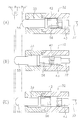
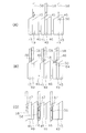
- FIG. 18 is a diagram illustrating the operation of the contact piece 5 according to the second embodiment.
- the first pressing member 33 described above moves from the off position Poff toward the on position Pon (see FIG. 13), as shown in FIG. 18 (A), the first protrusion 22a and the second protrusion 22b cause the first The 1st low rigidity part 72a and the 2nd low rigidity part 72b are pressed, respectively, and the 2nd contact 9 contacts the 1st contact 8.
- the pressing member 33 passes the on position Pon and reaches the overshoot position Pov, as shown in FIG. 18B, the pressing member 6 further moves, so that the first low rigidity portion 72a and the second low rigidity portion 72a are moved.
- the rigid portion 72b is bent.
- the pressing member 6 presses the first low-rigidity portion 72a and the second low-rigidity portion 72b, so that the first low-rigidity portion 72a and the second low-rigidity portion 72a can be pressed with a small force.
- the low rigidity portion 72b can be bent. Therefore, an increase in energy consumption at the actuator 7 can be suppressed.
- the load to the contact piece 5 by moving the 1st press member 33 to the overshoot position Pov can be released because the 1st low-rigidity part 72a and the 2nd low-rigidity part 72b bend. Thereby, the operation
- the configuration of the relay 1 may be changed.
- the number of the first contacts 8 and the second contacts 9 is not limited to one and may be two or more.
- the configuration related to the contact piece 5 is not limited to the configuration of the above embodiment, and may be changed.
- the shape of the pressing member 6 is not limited to that of the above embodiment, and may be changed.
- the first movable part 21 and the second movable part 22 may be integrated.
- the second pressing member 38 may be omitted. That is, the contact piece 5 may be directly pressed by the first pressing member 33.
- the configuration of the actuator 7 is not limited to the configuration of the above embodiment, and may be changed. Further, the configuration of the holding mechanism 32 may be changed.
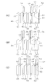
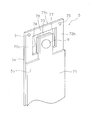
- FIG. 19 is a perspective view showing the contact piece 5 according to the first modification.
- the contact piece 5 may further include a connecting portion 72c that connects the first low-rigidity portion 72a and the second low-rigidity portion 72b.
- the first slit 76 and the second slit 77 may be connected by a third slit 78.
- the third slit 78 is provided between the connecting portion 72 c and the contact mounting portion 73 and extends in the width direction of the contact piece 5.
- connection part 72c By providing the connection part 72c, the twist of the 1st low-rigidity part 72a and the 2nd low-rigidity part 72b is suppressed. Thereby, the shift
- the pressing member 6 may press the first low-rigidity portion 72a and the second low-rigidity portion 72b.
- the pressing member 6 may press the connecting portion 72c.
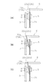
- FIG. 20 is a perspective view showing the contact piece 5 according to the second modification. As shown in FIG. 20, the thickness of the low-rigidity portions 72a and 72b and the thickness of the main body portion 71 may be the same.
- FIG. 21 is a perspective view showing a contact piece 5 according to a third modification.
- the thickness of the low-rigidity portions 72 a and 72 b may be thinner than the thickness of the main body portion 71.
Landscapes
- Physics & Mathematics (AREA)
- Electromagnetism (AREA)
- Electromagnets (AREA)
- Contacts (AREA)
- Push-Button Switches (AREA)
- Coupling Device And Connection With Printed Circuit (AREA)
Abstract
Description
本発明の課題は、リレーにおいて、オーバーシュート位置を経由させて押圧部材を移動させるアクチュエータが用いられる場合でも、アクチュエータでの消費エネルギーの増大を抑えると共に、安定した接触片の動作を得ることにある。
接触片は、互いに積層される複数の板バネを有してもよい。低剛性部を構成する板バネの枚数は、本体部を構成する板バネの枚数よりも少なくてもよい。この場合、低剛性部を構成する板バネの枚数が少ないことにより、低剛性部の剛性を小さくすることができる。
低剛性部の幅は、本体部の幅よりも小さくてもよい。この場合、低剛性部の幅が小さいことによって、低剛性部の剛性を小さくすることができる。
接触片は、低剛性部と本体部との間に設けられるスリットを有してもよい。この場合、スリットによって、低剛性部の剛性を小さくすることができる。
本体部は、第2接点が取り付けられる接点取付部を有してもよい。接点取付部は、第1低剛性部と第2低剛性部との間に配置されてもよい。接触片は、第1スリットと、第2スリットと、を有してもよい。第1スリットは、第1低剛性部と接点取付部との間に設けられ、接触片の長手方向に延びいてもよい。第2スリットは、第2低剛性部と接点取付部との間に設けられ、接触片の長手方向に延びていてもよい。この場合、第1スリットと第2スリットとによって、第1低剛性部と第2低剛性部との剛性を小さくすることができる。
低剛性部は、第1低剛性部と第2低剛性部とを連結する連結部をさらに有してもよい。これにより、第1低剛性部と第2低剛性部との捻れが抑えられ、それにより押圧位置のずれを抑えることができる。
押圧部材による低剛性部の押圧位置は、第2接点よりも接触片の先端側に位置してもよい。この場合、小さな力で低剛性部を大きく撓ませることができる。
アクチュエータは、押圧部材に係止することで押圧部材をオン位置に保持する保持部材をさらに有してもよい。この場合、磁力によって押圧部材をオン位置に保持する場合と比べて、衝撃、或いは、外部からの磁力の影響を受けずに、押圧部材をオン位置に安定的に保持することができる。
固定接点端子3は、銅などの導電性を有する材料で形成される。固定接点端子3の一端には第1接点8が取り付けられている。固定接点端子3の他端は、ベース2から外部に突出している。ベース2の内部には第1支持溝11が設けられており、固定接点端子3は第1支持溝11に嵌め込まれることで、ベース2に支持されている。
低剛性部72は、本体部71から先端側へ突出している。低剛性部72は、第2接点9よりも接触片5の先端側に位置する。低剛性部72は、上述した先端部14を含む。従って、押圧部材6は、低剛性部72を押圧する。押圧部材6による低剛性部72の押圧位置は、第2接点9よりも接触片5の先端側に位置する。
第1可動部21は、第1部分23と第2部分24とを有する。第1可動部21は、第1部分23と第2部分24との間で屈曲した形状を有する。詳細には、第1部分23は、支点17から接触片5に向かって斜めに延びる。第2部分24は、接触片5とアクチュエータ7と間に配置される。
第2可動部22は、凹部26を有する。接触片5の先端部14は、凹部26内に配置される。上述した接触部18は凹部26の縁の一部である。接触片5の先端部14は、接触部18に向かって屈曲した形状を有する。第1可動部21が支点17を中心に接触片5に近づく方向に回転すると、第1可動部21の先端によって第2可動部22が押される。これにより、第2可動部22は、接触部18が接触片5に向かう方向に、直線的に移動する。
第1押圧部材33が図3に示すオフ位置では、第1接点8と第2接点9とが乖離しており、リレー1はリセット状態となる。第1押圧部材33が図2に示すオン位置に移動すると、第2押圧部材38が第1押圧部材33によって押圧されることで、接触部18が接触片5を押圧する。これにより、接触片5が可動接点端子4に向かう方向に撓む。その結果、図2に示すように、第1接点8と第2接点9とが接触して、リレー1はセット状態となる。図3に示すように、第1押圧部材33がオン位置からオフ位置に戻ると、第1接点8と第2接点9とは乖離して、リレー1はリセット状態に戻る。
蓋部41は、保持部材42の先端に取り付けられる。蓋部41と保持部材42との内部には貫通孔44が設けられている。第1押圧部材33とプッシャー43と上述した鉄芯37とは、貫通孔44内において軸線方向に移動可能に配置される。
図10は、プッシャー43の斜視図である。図10に示すように、プッシャー43の外周面には、複数のガイド凸部51が設けられている。ガイド凸部51は、プッシャー43の周方向に間隔をあけて配置される。ガイド凸部51は、保持部材42のガイド溝49内と解除溝46内とにそれぞれ配置される。プッシャー43が軸線方向に移動するときには、ガイド凸部51がガイド溝49と解除溝46とに沿って移動する。プッシャー43の一方の端部には、孔52と、複数の傾斜面53とが設けられている。複数の傾斜面53は、孔52の周囲に配置される。プッシャー43の一方の端部は、鉄芯37によって押圧可能に設けられている。
係止部56は、複数の係止凸部58を有する。複数の係止凸部58は、係止部56の周方向に間隔をあけて配置される。複数の係止凸部58は、上述した解除溝46に沿って移動可能に設けられる。
次に、アクチュエータ7の動作について説明する。図13は、アクチュエータ7の動作状態を示す断面図である。図13では、第1押圧部材33のオン位置を「Pon」、オフ位置を「Poff」で示している。また、「Pov」は、後述する第1押圧部材33のオーバーシュート位置を示している。図14及び図15は、保持部材42の内周面と第1押圧部材33の係止凸部58との関係を平面上で示した図である。
アクチュエータ7への電圧が解除されると、接触片5の弾性力によって第1押圧部材33がオフ方向へ移動する。これにより、図14(C)に示すように、係止凸部58は、オフ方向へ移動することで、係止傾斜面47に接触する。係止凸部58の端部は、係止傾斜面47と同方向に傾斜している傾斜面64を有する。そのため、係止部56が、さらにオフ方向に押圧されることで、係止凸部58の傾斜面64が、係止傾斜面47に沿って滑る(矢印A4)。そして、係止凸部58は、係止傾斜面47と段部50とによって係止されて停止する。
次に、図13(C)に示すように、第1押圧部材33がオン位置Ponに位置している状態で、アクチュエータ7に電圧が印加されると、コイル部31によって鉄芯37にオン方向への電磁力が発生する。これにより、鉄芯37がオン方向へ移動して、プッシャー43が、接触片5の弾性力に抗して、第1押圧部材33をオン位置Ponからオン方向へ押圧する。これにより、図15(A)に示すように、係止凸部58がオン方向へ移動する(矢印A5)。
次に、アクチュエータ7への電圧が解除されると、接触片5の弾性力によって第1押圧部材33がオフ方向へ移動する。これにより、係止凸部58の傾斜面53が、解除傾斜面48に沿って滑り、図15(C)に示すように、解除溝46に対向する位置へ移動する。そして、係止凸部58が解除溝46に沿ってオフ方向に移動する。これにより、係止部56がオフ方向へ移動して、第1押圧部材33がオフ位置Poffに戻る。
押圧部材6が低剛性部72を押圧することで、小さな力で低剛性部72を撓ませることができる。そのため、アクチュエータ7での消費エネルギーの増大を抑えることができる。また、本体部71の厚さを低剛性部72の厚さよりも大きくすることができる。これにより、接触片5の導電性を向上させることができ、通電時の過剰な温度上昇を抑えることができる。
次に第2実施形態に係る接触片5に付いて説明する。図16は、第2実施形態に係る接触片5の斜視図である。図16に示すように、第2実施形態に係る接触片5は、本体部71と第1低剛性部72aと第2低剛性部72bとを有する。本体部71は、接点取付部73を有する。接点取付部73には第2接点9が取り付けられる。接点取付部73は、第1低剛性部72aと第2低剛性部72bとの間に配置される。
第1低剛性部72aの厚さは本体部71の厚さよりも薄い。第2低剛性部72bの厚さは本体部71の厚さよりも薄い。第1低剛性部72aを構成する板バネ5aの枚数は、本体部71を構成する板バネ5a,5bの枚数よりも少ない。第2低剛性部72bを構成する板バネ5aの枚数は、本体部71を構成する板バネ5a,5bの枚数よりも少ない。本実施形態では、第1低剛性部72aと第2低剛性部72bとを構成する板バネの枚数は、それぞれ1枚であり、本体部71を構成する板バネ5a,5bの枚数は2枚である。ただし、第1低剛性部72aと第2低剛性部72bとを構成する板バネの枚数は、それぞれ1枚より多くてもよい。本体部71を構成する板バネ5a,5bの枚数は2枚より多くてもよい。
図17は、第2実施形態に係る押圧部材6の一部(第2可動部22)を示す斜視図である。図17に示すように、押圧部材6は、第1突出部22aと第2突出部22bとを有する。第1突出部22aと第2突出部22bとは、接触片5の幅方向に互いに離れて配置される。第1突出部22aの先端は、第1低剛性部72aの第1孔74に挿入される。第2突出部22bの先端は、第2低剛性部72bの第2孔75に挿入される。第1突出部22aと第2突出部22bとの間には凹部22cが設けられる。
リレー1の構成は変更されてもよい。例えば、第1接点8及び第2接点9の数は、それぞれ1つに限らず、2つ以上であってもよい。接触片5に関する構成は、上記の実施形態の構成に限らず、変更されてもよい。
アクチュエータ7の構成は上記の実施形態の構成に限らず、変更されてもよい。また、保持機構32の構成が変更されてもよい。
図20は、第2変形例に係る接触片5を示す斜視図である。図20に示すように、低剛性部72a,72bの厚さと本体部71の厚さとが同じであってもよい。
3 固定接点端子
9 第2接点
5 接触片
6 押圧部材
7 アクチュエータ
71 本体部
72 低剛性部
5a,5b 板バネ
72a 第1低剛性部
72b 第2低剛性部
73 接点取付部
76 第1スリット
77 第2スリット
72c 連結部
42 保持部材
Claims (14)
- 第1接点と、
前記第1接点が取り付けられる端子と、
前記第1接点と対向して配置される第2接点と、
前記第2接点が取り付けられる接触片と、
前記第1接点と前記第2接点とが非接触状態となるオフ位置と、前記接触片を押圧することで前記第1接点と前記第2接点とが接触状態となるオン位置と、に移動可能に設けられる押圧部材と、
前記押圧部材を、前記オフ位置から前記オン位置を越えたオーバーシュート位置を経て前記オン位置に移動させるアクチュエータと、
を備え、
前記接触片は、本体部と、前記本体部よりも剛性の低い低剛性部と、を有し、
前記押圧部材は、前記低剛性部を押圧する、
リレー。 - 前記低剛性部は、前記本体部よりも厚さが薄い、
請求項1に記載のリレー。 - 前記接触片は、互いに積層される複数の板バネを有し、
前記低剛性部を構成する板バネの枚数は、前記本体部を構成する板バネの枚数よりも少ない、
請求項1又は2に記載のリレー。 - 前記低剛性部は、前記第2接点よりも前記接触片の先端側に位置する、
請求項1から3のいずれかに記載のリレー。 - 前記低剛性部の幅は、前記本体部の幅よりも小さい、
請求項1から4のいずれかに記載のリレー。 - 前記接触片は、前記低剛性部と前記本体部との間に設けられるスリットを有する、
請求項1から5のいずれかに記載のリレー。 - 前記低剛性部は、第1低剛性部と第2低剛性部とを有し、
前記第1低剛性部と前記第2低剛性部とは、前記本体部から前記接触片の長手方向に延び、前記接触片の幅方向に互いに離れて配置される、
請求項1から6のいずれかに記載のリレー。 - 前記本体部は、前記第1低剛性部と前記第2低剛性部との間に配置され前記第2接点が取り付けられる接点取付部を有し、
前記接触片は、
前記第1低剛性部と前記接点取付部との間に設けられ前記接触片の長手方向に延びる第1スリットと、
前記第2低剛性部と前記接点取付部との間に設けられ前記接触片の長手方向に延びる第2スリットと、
を有する、
請求項7に記載のリレー。 - 前記第1スリットと前記第2スリットとは、前記第2接点よりも前記接触片の基端側の位置まで延びている、
請求項8に記載のリレー。 - 前記低剛性部は、前記第1低剛性部と前記第2低剛性部とを連結する連結部をさらに有する、
請求項7から9のいずれかに記載のリレー。 - 前記押圧部材は、前記第1低剛性部と前記第2低剛性部とを押圧する、
請求項7から10のいずれかに記載のリレー。 - 前記押圧部材は、前記連結部を押圧する、
請求項10に記載のリレー。 - 前記押圧部材による前記低剛性部の押圧位置は、前記第2接点よりも前記接触片の先端側に位置する、
請求項1から12のいずれかに記載のリレー。 - 前記アクチュエータは、前記押圧部材に係止することで前記押圧部材を前記オン位置に保持する保持部材を有する、
請求項1から13のいずれかに記載のリレー。
Priority Applications (3)
| Application Number | Priority Date | Filing Date | Title |
|---|---|---|---|
| CN201680048513.7A CN107924789B (zh) | 2015-12-11 | 2016-11-16 | 继电器 |
| DE112016005641.9T DE112016005641B4 (de) | 2015-12-11 | 2016-11-16 | Relais |
| US15/754,772 US10714291B2 (en) | 2015-12-11 | 2016-11-16 | Relay |
Applications Claiming Priority (2)
| Application Number | Priority Date | Filing Date | Title |
|---|---|---|---|
| JP2015-242409 | 2015-12-11 | ||
| JP2015242409A JP6421745B2 (ja) | 2015-12-11 | 2015-12-11 | リレー |
Publications (1)
| Publication Number | Publication Date |
|---|---|
| WO2017098874A1 true WO2017098874A1 (ja) | 2017-06-15 |
Family
ID=59013064
Family Applications (1)
| Application Number | Title | Priority Date | Filing Date |
|---|---|---|---|
| PCT/JP2016/083974 Ceased WO2017098874A1 (ja) | 2015-12-11 | 2016-11-16 | リレー |
Country Status (5)
| Country | Link |
|---|---|
| US (1) | US10714291B2 (ja) |
| JP (1) | JP6421745B2 (ja) |
| CN (1) | CN107924789B (ja) |
| DE (1) | DE112016005641B4 (ja) |
| WO (1) | WO2017098874A1 (ja) |
Families Citing this family (7)
| Publication number | Priority date | Publication date | Assignee | Title |
|---|---|---|---|---|
| JP6458705B2 (ja) * | 2015-10-29 | 2019-01-30 | オムロン株式会社 | リレー |
| JP6471678B2 (ja) * | 2015-10-29 | 2019-02-20 | オムロン株式会社 | 接触片ユニット及びリレー |
| JP6414019B2 (ja) | 2015-10-29 | 2018-10-31 | オムロン株式会社 | リレー |
| CN109585229B (zh) * | 2018-10-30 | 2020-02-28 | 宁波高灵电子有限公司 | 一种高柔韧度的继电器动簧片组件和继电器 |
| WO2020110912A1 (ja) * | 2018-11-28 | 2020-06-04 | パナソニックIpマネジメント株式会社 | 接点装置 |
| US11328886B1 (en) * | 2020-11-06 | 2022-05-10 | Song Chuan Precision Co., Ltd. | Relay structure |
| DE102023108668A1 (de) * | 2023-04-04 | 2024-10-10 | E. Dold & Söhne Gmbh & Co. Kg | Elektromagnetisches Relais |
Citations (9)
| Publication number | Priority date | Publication date | Assignee | Title |
|---|---|---|---|---|
| JPS474698Y1 (ja) * | 1967-10-18 | 1972-02-18 | ||
| JPS6318182A (ja) * | 1986-07-09 | 1988-01-26 | Nippon Denso Co Ltd | スタ−タ用電磁ソレノイドのプランジヤ機構 |
| JPS6431315A (en) * | 1987-07-28 | 1989-02-01 | Matsushita Electric Works Ltd | Driving method for contact point spring |
| JPH11273533A (ja) * | 1998-03-20 | 1999-10-08 | Omron Corp | 電磁継電器 |
| JP2002343215A (ja) * | 2001-05-15 | 2002-11-29 | Matsushita Electric Works Ltd | 電磁リレー |
| JP2012129206A (ja) * | 2010-12-16 | 2012-07-05 | Tyco Electronics Austria Gmbh | 改善されたコンタクトばねを備えるリレー |
| JP2015088463A (ja) * | 2013-09-27 | 2015-05-07 | オムロン株式会社 | 接点機構部およびこれを備えた電磁継電器 |
| JP5741679B1 (ja) * | 2013-12-27 | 2015-07-01 | オムロン株式会社 | 電磁継電器 |
| WO2016039220A1 (ja) * | 2014-09-08 | 2016-03-17 | オムロン株式会社 | 接点開閉装置 |
Family Cites Families (80)
| Publication number | Priority date | Publication date | Assignee | Title |
|---|---|---|---|---|
| US1339922A (en) * | 1911-03-23 | 1920-05-11 | Westinghouse Electric & Mfg Co | Switch for electric circuits |
| US1354708A (en) * | 1917-07-25 | 1920-10-05 | Monitor Controller Co | Multivalue overload-relay |
| US1369934A (en) * | 1920-02-16 | 1921-03-01 | Weyerhaeuser Forest Products | Branding-machine |
| US2005195A (en) * | 1933-07-31 | 1935-06-18 | Ira E Mccabe | Delayed action switch mechanism |
| US2157844A (en) * | 1936-08-28 | 1939-05-09 | Westinghouse Electric & Mfg Co | Electromagnet with shading coil |
| US2654009A (en) * | 1950-01-28 | 1953-09-29 | Westinghouse Electric Corp | Circuit breaker |
| US2663774A (en) * | 1950-07-22 | 1953-12-22 | Westinghouse Electric Corp | Electromagnetic trip circuit breaker |
| US2959962A (en) * | 1957-10-02 | 1960-11-15 | Epstein Saul | Electromagnetic fluid pressure responsive device |
| US3098912A (en) * | 1961-08-28 | 1963-07-23 | Heinemann Electric Co | Movable arm actuated interconnected circuit breakers |
| US3344372A (en) * | 1963-01-18 | 1967-09-26 | Heinemann Electric Co | Time delay tube reset device |
| US3234344A (en) * | 1963-01-18 | 1966-02-08 | Heinemann Electric Co | Electromagnetic circuit breaker having a solenoid with a hydraulic time delay means |
| US3272934A (en) * | 1963-12-30 | 1966-09-13 | Heinemann Electric Co | Circuit breaker unit for abnormally high inrush currents and/or inrush currents of long duration |
| US3268043A (en) * | 1964-02-14 | 1966-08-23 | Chad W Pennebaker | Magnetic clutch |
| DE1488740A1 (de) * | 1964-10-23 | 1969-07-17 | Schwarzkopf Dipl El Ing Gabrie | Elektromagnetischer Schwinganker |
| US3363571A (en) * | 1965-08-02 | 1968-01-16 | Reynolds Products | Metering pump and system |
| US3517357A (en) * | 1968-04-04 | 1970-06-23 | Heinemann Electric Co | Electromagnetic device having a short circuited turn |
| US3566320A (en) * | 1969-06-05 | 1971-02-23 | Heinemann Electric Co | Electromagnetic device having a dual coil for independent tripping thereof |
| US3773992A (en) * | 1971-08-02 | 1973-11-20 | Heinemann Electric Co | Circuit breaker case |
| US3791408A (en) * | 1972-05-31 | 1974-02-12 | Yuken Kogyo Co Ltd | Electromagnetic pressure-telecontrolling valve |
| US3788597A (en) * | 1972-05-31 | 1974-01-29 | Yukon Kogyo Co Ltd | Electromagnetic flow controlling valve |
| US4267539A (en) * | 1979-08-02 | 1981-05-12 | Heinemann Electric Company | Circuit breaker having a cam for external adjustment of its trip point |
| FR2466844A1 (fr) * | 1979-09-28 | 1981-04-10 | Telemecanique Electrique | Electro-aimant comportant un noyau-plongeur muni d'un aimant monostable ou bistable |
| JPS59159504A (ja) * | 1983-03-02 | 1984-09-10 | Tokai Rika Co Ltd | 保持マグネツト |
| US4515343A (en) * | 1983-03-28 | 1985-05-07 | Fev Forschungsgesellschaft fur Energietechnik und ver Brennungsmotoren mbH | Arrangement for electromagnetically operated actuators |
| US4683453A (en) * | 1985-11-25 | 1987-07-28 | Automatic Switch Company | Solenoid actuator with fastener |
| US5207410A (en) * | 1992-06-03 | 1993-05-04 | Siemens Automotive L.P. | Means for improving the opening response of a solenoid operated fuel valve |
| US5389910A (en) * | 1992-12-08 | 1995-02-14 | Alliedsignal Inc. | Solenoid encasement with variable reluctance |
| IT1287151B1 (it) * | 1996-11-11 | 1998-08-04 | Abb Research Ltd | Attuatore magnetico |
| US5845672A (en) * | 1996-12-10 | 1998-12-08 | General Motors Corporation | Solenoid coil positioning assembly |
| US6125803A (en) * | 1997-09-22 | 2000-10-03 | Toyota Jidosha Kabushiki Kaisha | Electromagnetically driven valve for an internal combustion engine |
| US6049264A (en) * | 1997-12-09 | 2000-04-11 | Siemens Automotive Corporation | Electromagnetic actuator with composite core assembly |
| US6157277A (en) * | 1997-12-09 | 2000-12-05 | Siemens Automotive Corporation | Electromagnetic actuator with improved lamination core-housing connection |
| US6044813A (en) * | 1997-12-09 | 2000-04-04 | Siemens Automotive Corporation | Electromagnetic actuator with detached lower collar to align with cylinder head bore |
| US20010040018A1 (en) * | 1997-12-09 | 2001-11-15 | Dennis Bulgatz | Electromagnetic actuator with lamination stack-housing dovetail connection |
| US6092784A (en) * | 1997-12-30 | 2000-07-25 | Dana Corporation | Coil assembly useful in solenoid valves |
| US6155503A (en) * | 1998-05-26 | 2000-12-05 | Cummins Engine Company, Inc. | Solenoid actuator assembly |
| JP2983523B1 (ja) | 1998-08-03 | 1999-11-29 | ザ・パック株式会社 | 優れた剥離性を有する抗菌性食品包装用シート材 |
| US7021603B2 (en) * | 1998-10-08 | 2006-04-04 | Wladyslaw Wygnaski | Electromagnetic actuator and integrated actuator and fluid flow control valve |
| JP2001126918A (ja) * | 1999-10-28 | 2001-05-11 | Honda Motor Co Ltd | 電磁アクチュエータ |
| JP2001126921A (ja) * | 1999-10-27 | 2001-05-11 | Honda Motor Co Ltd | 電磁アクチュエータのコア |
| JP2001126922A (ja) * | 1999-10-27 | 2001-05-11 | Honda Motor Co Ltd | 電磁アクチュエータのコア |
| JP2002083712A (ja) * | 1999-12-09 | 2002-03-22 | Sumitomo Electric Ind Ltd | 電磁アクチュエータ及び内燃機関用弁開閉機構 |
| US6373363B1 (en) * | 2000-03-28 | 2002-04-16 | Delphi Technologies, Inc. | Dual coil solenoid for a gas direct injection fuel injector |
| DE10037399A1 (de) * | 2000-08-01 | 2002-02-14 | Daimler Chrysler Ag | Verfahren zur Herstellung eines elektromagnetischen Aktuators |
| DE10053596A1 (de) * | 2000-10-28 | 2002-05-02 | Daimler Chrysler Ag | Elektromagnetischer Aktuator zur Betätigung eines Stellgliedes |
| US6677844B1 (en) * | 2002-10-21 | 2004-01-13 | Adams Rite Aerospace, Inc. | Quick-return electro-mechanical actuator |
| DE10261811B4 (de) * | 2002-12-19 | 2005-01-20 | Siemens Ag | Elektromagnetischer Antrieb |
| US7252114B2 (en) * | 2003-05-30 | 2007-08-07 | Camcon Limited | Electromagnetic fluid flow control valve |
| US7209020B2 (en) * | 2003-06-09 | 2007-04-24 | Borgwarner Inc. | Variable force solenoid |
| EP1812929A4 (en) * | 2004-10-01 | 2017-05-10 | Novelorg Inc. | Proportional electromagnet actuator and control system |
| CA2622425C (en) * | 2005-09-13 | 2012-04-10 | Armour Magnetic Components, Inc. | Solenoid actuator and method for making and using same |
| FR2896615A1 (fr) * | 2006-01-20 | 2007-07-27 | Areva T & D Sa | Actionneur magnetique a aimant permanent a volume reduit |
| US7741941B2 (en) * | 2006-11-30 | 2010-06-22 | Honeywell International Inc. | Dual armature solenoid valve assembly |
| US8186379B2 (en) * | 2007-06-26 | 2012-05-29 | Advics Co., Ltd. | Electromagnetic valve and method for manufacturing the same |
| FR2925754B1 (fr) * | 2007-12-20 | 2015-06-05 | Valeo Sys Controle Moteur Sas | Ensemble d'un electroaimant et d'une palette d'electroaimant et actionneur de soupape comprenant un tel ensemble |
| DE102008008118B4 (de) * | 2008-02-08 | 2026-01-15 | Schaeffler Technologies AG & Co. KG | Elektromagnetische Stelleinheit für ein hydraulisches Wegeventil |
| EP2182531B1 (en) * | 2008-10-29 | 2014-01-08 | Sauer-Danfoss ApS | Valve actuator |
| DE102008059012A1 (de) * | 2008-11-26 | 2010-05-27 | Schaeffler Kg | Elektromagnetische Stelleinheit für ein hydraulisches Wegeventil und Verfahren zu dessen Montage |
| US7866301B2 (en) * | 2009-01-26 | 2011-01-11 | Caterpillar Inc. | Self-guided armature in single pole solenoid actuator assembly and fuel injector using same |
| DE102009006355A1 (de) * | 2009-01-28 | 2010-07-29 | Schaeffler Technologies Gmbh & Co. Kg | Proportionalmagnet für ein hydraulisches Wegeventil und Verfahren zu dessen Herstellung |
| CN102237207A (zh) | 2010-05-06 | 2011-11-09 | 刘伟亮 | 开关装置及应用 |
| CN201766036U (zh) | 2010-09-06 | 2011-03-16 | 厦门宏发电力电器有限公司 | 具有双柔性推动连接的磁保持继电器 |
| JP2012074138A (ja) | 2010-09-27 | 2012-04-12 | Panasonic Corp | 電磁リレー |
| US20120153199A1 (en) * | 2010-12-20 | 2012-06-21 | Robertshaw Controls Company | Solenoid for a Direct Acting Valve Having Stepped Guide Tube |
| US20120268225A1 (en) * | 2011-04-19 | 2012-10-25 | Honeywell International Inc. | Solenoid actuator with surface features on the poles |
| CN202423142U (zh) | 2012-01-16 | 2012-09-05 | 浙江朗万电气科技有限公司 | 一种应用于磁保持继电器中的铰链型驱动机构 |
| FR2999014B1 (fr) * | 2012-12-03 | 2016-01-15 | Schneider Electric Ind Sas | Actionneur a shunt magnetothermique, en particulier pour le declenchement de disjoncteur |
| CN203013634U (zh) | 2013-01-09 | 2013-06-19 | 厦门宏发电力电器有限公司 | 一种直动式磁路结构的磁保持继电器 |
| GB2511569B (en) | 2013-03-08 | 2015-05-06 | Christopher John Stanton | Improved switch and associated methods |
| CN203205353U (zh) | 2013-04-19 | 2013-09-18 | 湖南航天经济发展有限公司 | 一种增加负荷触点压力的磁保持继电器 |
| JP6393025B2 (ja) | 2013-07-01 | 2018-09-19 | 富士通コンポーネント株式会社 | 電磁継電器 |
| DE102013214209A1 (de) | 2013-07-19 | 2015-01-22 | Tyco Electronics Amp Gmbh | Elektrischer Schaltkontakt und Schaltvorrichtung mit selbigem |
| DE112015001356T5 (de) * | 2014-03-20 | 2016-12-01 | GM Global Technology Operations LLC (n. d. Ges. d. Staates Delaware) | Aufbau eines elektromagnetischen aktors |
| US9659698B2 (en) * | 2014-05-22 | 2017-05-23 | Husco Automotive Holdings Llc | Electromechanical solenoid having a pole piece alignment member |
| CN204668248U (zh) | 2015-04-15 | 2015-09-23 | 浙江正泰电器股份有限公司 | 磁保持继电器的接触系统 |
| US9502167B1 (en) * | 2015-11-18 | 2016-11-22 | Hamilton Sundstrand Corporation | High temperature electromagnetic actuator |
| US9702477B1 (en) * | 2015-12-17 | 2017-07-11 | Glen A. Robertson | Power versatile and energy efficient electric coaxial valve |
| DE102016107461A1 (de) * | 2016-04-22 | 2017-10-26 | Eto Magnetic Gmbh | Aktorvorrichtung und Verfahren zum Betrieb einer Aktorvorrichtung |
| DE102017103027A1 (de) * | 2017-02-15 | 2018-08-16 | Rausch & Pausch Gmbh | Linearaktuator |
| JP6933099B2 (ja) * | 2017-11-16 | 2021-09-08 | 株式会社ジェイテクト | 断続装置 |
-
2015
- 2015-12-11 JP JP2015242409A patent/JP6421745B2/ja active Active
-
2016
- 2016-11-16 DE DE112016005641.9T patent/DE112016005641B4/de active Active
- 2016-11-16 CN CN201680048513.7A patent/CN107924789B/zh active Active
- 2016-11-16 US US15/754,772 patent/US10714291B2/en active Active
- 2016-11-16 WO PCT/JP2016/083974 patent/WO2017098874A1/ja not_active Ceased
Patent Citations (9)
| Publication number | Priority date | Publication date | Assignee | Title |
|---|---|---|---|---|
| JPS474698Y1 (ja) * | 1967-10-18 | 1972-02-18 | ||
| JPS6318182A (ja) * | 1986-07-09 | 1988-01-26 | Nippon Denso Co Ltd | スタ−タ用電磁ソレノイドのプランジヤ機構 |
| JPS6431315A (en) * | 1987-07-28 | 1989-02-01 | Matsushita Electric Works Ltd | Driving method for contact point spring |
| JPH11273533A (ja) * | 1998-03-20 | 1999-10-08 | Omron Corp | 電磁継電器 |
| JP2002343215A (ja) * | 2001-05-15 | 2002-11-29 | Matsushita Electric Works Ltd | 電磁リレー |
| JP2012129206A (ja) * | 2010-12-16 | 2012-07-05 | Tyco Electronics Austria Gmbh | 改善されたコンタクトばねを備えるリレー |
| JP2015088463A (ja) * | 2013-09-27 | 2015-05-07 | オムロン株式会社 | 接点機構部およびこれを備えた電磁継電器 |
| JP5741679B1 (ja) * | 2013-12-27 | 2015-07-01 | オムロン株式会社 | 電磁継電器 |
| WO2016039220A1 (ja) * | 2014-09-08 | 2016-03-17 | オムロン株式会社 | 接点開閉装置 |
Also Published As
| Publication number | Publication date |
|---|---|
| DE112016005641B4 (de) | 2026-03-19 |
| JP6421745B2 (ja) | 2018-11-14 |
| JP2017107812A (ja) | 2017-06-15 |
| CN107924789B (zh) | 2019-08-13 |
| US20180269018A1 (en) | 2018-09-20 |
| CN107924789A (zh) | 2018-04-17 |
| US10714291B2 (en) | 2020-07-14 |
| DE112016005641T5 (de) | 2018-08-30 |
Similar Documents
| Publication | Publication Date | Title |
|---|---|---|
| JP6421745B2 (ja) | リレー | |
| US11289296B2 (en) | Contact device and relay using the same | |
| JP6399434B2 (ja) | 接点装置 | |
| JP5930092B1 (ja) | リレー | |
| JP6471678B2 (ja) | 接触片ユニット及びリレー | |
| JP6264236B2 (ja) | 接点開閉装置 | |
| WO2011125142A1 (ja) | 有極電磁石及び電磁接触器 | |
| US11538647B2 (en) | Electromagnetic relay | |
| JP6575343B2 (ja) | リレー | |
| US20080001689A1 (en) | Electromagnetic relay | |
| JP7819732B2 (ja) | 電磁継電器 | |
| WO2020026479A1 (ja) | リレー | |
| JP2012199139A (ja) | 接点装置及びそれを用いた電磁開閉装置 | |
| WO2020026478A1 (ja) | リレー | |
| JP7569979B2 (ja) | 接点装置及び電磁継電器 | |
| JP4920095B2 (ja) | 電磁ソレノイド | |
| JP7468277B2 (ja) | 電磁継電器 | |
| JP2010062042A (ja) | リレー | |
| JP5541819B2 (ja) | リレー | |
| JP2011192488A (ja) | 電磁接触器 | |
| JP2007103201A (ja) | プッシュスイッチ | |
| CN105281516A (zh) | 致动器 | |
| JP2012199151A (ja) | 接点装置 |
Legal Events
| Date | Code | Title | Description |
|---|---|---|---|
| 121 | Ep: the epo has been informed by wipo that ep was designated in this application |
Ref document number: 16872774 Country of ref document: EP Kind code of ref document: A1 |
|
| WWE | Wipo information: entry into national phase |
Ref document number: 15754772 Country of ref document: US |
|
| WWE | Wipo information: entry into national phase |
Ref document number: 112016005641 Country of ref document: DE |
|
| 122 | Ep: pct application non-entry in european phase |
Ref document number: 16872774 Country of ref document: EP Kind code of ref document: A1 |
|
| WWG | Wipo information: grant in national office |
Ref document number: 112016005641 Country of ref document: DE |