WO2017094559A1 - 反射特性測定システム - Google Patents
反射特性測定システム Download PDFInfo
- Publication number
- WO2017094559A1 WO2017094559A1 PCT/JP2016/084552 JP2016084552W WO2017094559A1 WO 2017094559 A1 WO2017094559 A1 WO 2017094559A1 JP 2016084552 W JP2016084552 W JP 2016084552W WO 2017094559 A1 WO2017094559 A1 WO 2017094559A1
- Authority
- WO
- WIPO (PCT)
- Prior art keywords
- light
- correction
- unit
- opening
- characteristic
- Prior art date
- Legal status (The legal status is an assumption and is not a legal conclusion. Google has not performed a legal analysis and makes no representation as to the accuracy of the status listed.)
- Ceased
Links
Images






Classifications
-
- G—PHYSICS
- G01—MEASURING; TESTING
- G01J—MEASUREMENT OF INTENSITY, VELOCITY, SPECTRAL CONTENT, POLARISATION, PHASE OR PULSE CHARACTERISTICS OF INFRARED, VISIBLE OR ULTRAVIOLET LIGHT; COLORIMETRY; RADIATION PYROMETRY
- G01J3/00—Spectrometry; Spectrophotometry; Monochromators; Measuring colours
- G01J3/46—Measurement of colour; Colour measuring devices, e.g. colorimeters
- G01J3/50—Measurement of colour; Colour measuring devices, e.g. colorimeters using electric radiation detectors
-
- G—PHYSICS
- G01—MEASURING; TESTING
- G01N—INVESTIGATING OR ANALYSING MATERIALS BY DETERMINING THEIR CHEMICAL OR PHYSICAL PROPERTIES
- G01N21/00—Investigating or analysing materials by the use of optical means, i.e. using sub-millimetre waves, infrared, visible or ultraviolet light
- G01N21/17—Systems in which incident light is modified in accordance with the properties of the material investigated
- G01N21/25—Colour; Spectral properties, i.e. comparison of effect of material on the light at two or more different wavelengths or wavelength bands
- G01N21/27—Colour; Spectral properties, i.e. comparison of effect of material on the light at two or more different wavelengths or wavelength bands using photo-electric detection ; circuits for computing concentration
Definitions
- the present invention relates to a system for measuring light reflection characteristics on the surface of a sample.
- the sample placed in the opening of the integrating sphere is illuminated using the integrating sphere as a colorimetric object, and the reflected light from the sample is received, and the surface color of the sample (specifically, the object color)
- a color measurement device that measures the above (for example, Patent Document 1).
- the size of the measurement opening (also referred to as measurement opening) in the integrating sphere is appropriately determined according to the type and size of the sample. And the measurement (average value measurement, spot measurement) which made the part distribute
- the diameter of the measurement opening is set to about 3 mm to 20 mm according to the size of the integrating sphere. This is because the aperture diameter of the measurement aperture is set within a range in which measurement of the object color is unlikely to occur with respect to the diameter of the integrating sphere.
- the color measurement device if a two-dimensional distribution of colors in a measurement area of a predetermined size can be measured, the selection of the measurement area, simultaneous measurement of a plurality of distant places, measurement of an elongated area, etc. Intricate shapes such as uneven color and patterned objects in the measurement area can be measured. Such a measurement can be realized in a mode in which the average value of the color of the circular measurement area arranged in the circular measurement opening on the surface of the sample is measured as in the conventional color measurement device. There wasn't.
- the color measuring device capable of measuring the two-dimensional color distribution is not limited to a large type installed on a desk or the like, but is a small and lightweight portable type that can be carried by hand. Can be considered.
- the diameter of the measurement opening facing the sample must be larger than the size of the integrating sphere.
- the light irradiated on the sample is reflected by the sample against the light reflected so as to diffuse in the integrating sphere.
- the ratio of light reflected from the surface and returning to the inside of the integrating sphere increases.
- the illumination light in the integrating sphere can be modulated depending on the surface color of the sample.
- an error is likely to occur in the result of color measurement by the color measuring device.
- the present invention has been made in view of the above problems, and an object of the present invention is to provide a small reflection characteristic measurement system capable of measuring the reflection characteristic of light on the surface of a sample with high accuracy.
- the reflection characteristic measurement system includes an integrating sphere, a light source unit, a detection unit, an acquisition unit, a setting unit, and a correction unit.
- the integrating sphere passes a reflected light from the device under test with a first opening forming a measurement opening arranged to cover the device under test, and facing the first opening. And a second opening forming a detection opening.
- the light source unit irradiates light on the inner wall surface of the integrating sphere.
- the detection unit includes the reflected light from the two-dimensional region of the surface of the object to be measured that is incident on the integrating sphere through the measurement opening, and the periphery of the first opening in the integrating sphere.
- the reflected light from the correction region located at is received through the detection aperture, and signals corresponding to three or more light in different wavelength ranges are output.
- the acquisition unit acquires a two-dimensional distribution of light reflection characteristics in the two-dimensional region based on a signal output from the detection unit, and acquires a characteristic value related to the light reflection property in the correction region. To do.
- the setting unit has a reflection characteristic of light in the correction region acquired by the acquisition unit according to a signal output from the detection unit when a reference object is arranged to cover the measurement opening.
- the first characteristic value according to the above and the light in the correction area acquired by the acquisition unit in response to a signal output from the detection unit when the sample is arranged to cover the measurement opening Based on the second characteristic value related to the reflection characteristic, a conversion rule capable of converting the second characteristic value into the first characteristic value is set.
- the correction unit is acquired by the acquisition unit according to a signal output from the detection unit when the sample is arranged so as to cover the measurement opening by conversion based on the conversion rule. A two-dimensional distribution of the reflection characteristic in the two-dimensional region of the sample is corrected.
- the reflection characteristic measurement system since the influence of the modulation of the illumination light according to the reflection characteristic of the light on the surface of the sample is suppressed, the reflection characteristic of the light on the surface of the sample is measured with high accuracy. A small reflection characteristic measuring system can be realized.
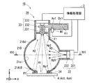
- FIG. 1 is a diagram illustrating a schematic configuration of a reflection characteristic measurement system according to an embodiment.
- FIG. 2 is a diagram illustrating the bottom of the integrating sphere as viewed from the inside.
- FIG. 3 is a plan view showing a configuration example of the rotary filter unit.
- FIG. 4 is a diagram illustrating a variation of the correction area.
- FIG. 5 is a diagram illustrating a variation of the correction area.
- FIG. 6 is a block diagram illustrating a configuration example of the information processing unit.
- FIG. 7 is a block diagram illustrating a functional configuration realized by the information processing unit.
- FIG. 8 is a top view illustrating the appearance of the top surface of the sample.
- FIG. 9 is a flowchart illustrating an operation flow related to colorimetry processing in the information processing unit.
- FIG. 9 is a flowchart illustrating an operation flow related to colorimetry processing in the information processing unit.
- FIG. 10 is a flowchart illustrating an operation flow related to colorimetry processing in the information processing unit.
- FIG. 11 is a diagram illustrating the relationship between the correction condition and ⁇ Lab in the simulation.
- FIG. 12 is a diagram illustrating a cross section of an integrating sphere according to the first modification.
- FIG. 13 is a diagram illustrating a state in which the bottom of the integrating sphere according to the first modification is viewed from the inside.
- FIG. 14 is a diagram illustrating the appearance of the bottom of the integrating sphere according to the first modification.
- FIG. 15 is a diagram illustrating a cross section of an integrating sphere according to the second modification.
- FIG. 16 is a diagram illustrating a state in which the bottom of the integrating sphere according to the second modification is viewed from the inside.
- FIG. 1 is a diagram illustrating a schematic configuration of a reflection characteristic measurement system 1 according to an embodiment.
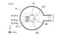
- FIG. 2 is a diagram illustrating a state in which the bottom of the integrating sphere 21 is viewed from the inside. Specifically, FIG. 2 is a diagram showing an XY cross section at a position indicated by a one-dot chain line II-II in FIG.
- the reflection characteristic measurement system 1 is a system for measuring a characteristic (also referred to as a reflection characteristic) that reflects light on the surface of the measurement object 4 including the reference object 4st for calibration and the sample 4sm.
- the reflection characteristic includes, for example, a numerical value related to the object color.
- a white calibration plate also referred to as a calibration white plate or the like may be employed as the calibration reference object 4st.
- the reflection characteristic measurement system 1 includes a reflection characteristic measurement unit 2 and an information processing unit 3.
- the reflection characteristic measuring unit 2 and the information processing unit 3 may be configured integrally, whereby the reflection characteristic measuring system 1 may be configured, or the reflection characteristic measuring unit 2 and the information processing unit 3 may be configured. May be configured separately, so that the reflection characteristic measurement system 1 may be configured.
- the information processing unit 3 is configured by, for example, a personal computer. Then, the reflection characteristic measurement unit 2 and the information processing unit 3 are connected so that data communication is possible, for example, by a cable or wireless communication.
- the reflection characteristic measurement unit 2 includes an integrating sphere 21, an illumination unit 22, and a light receiving unit 23.
- the integrating sphere 21 is a spherical member whose inner wall surface 21si diffuses and reflects light (diffuse reflection) almost completely.
- the inner wall surface 21si can be formed, for example, by applying a white paint such as barium sulfate to the inner surface of a spherical member.
- the color of the inner wall surface 21si of the integrating sphere 21 is substantially equivalent to the color of the surface of the calibration white plate.
- the integrating sphere 21 has openings Hp0, Hp1, and Hp2 that form three openings H0, H1, and H2 whose inner space is open to the outer space. Each opening H0, H1. As H2, for example, a substantially circular one can be adopted.
- the opening Hp0 is a part where the opening H0 for irradiating the inner wall surface 21si of the integrating sphere 21 with the light from the illumination unit 22 is formed.
- the opening Hp1 is a portion (also referred to as a first opening) that forms a measurement opening H1 that is arranged so as to cover the DUT 4.
- the opening Hp ⁇ b> 1 is provided at the bottom of the integrating sphere 21.
- the opening portion Hp2 is a portion (also referred to as a second opening portion) that forms a detection opening H2 that opposes the first opening portion Hp1 and allows the reflected light from the DUT 4 to pass therethrough.
- the illumination unit 22 is a part that irradiates light to the object to be measured 4 in order to measure the light reflection characteristics on the surface of the object to be measured 4.
- the illumination unit 22 includes a light emitting circuit 221 and a light source unit 222.
- the light emitting circuit 221 is a circuit for causing the light source unit 222 to emit light.
- the light source part 222 is a part that irradiates the inner wall surface 21si of the integrating sphere 21 with light.
- a halogen lamp, a xenon lamp, a light emitting diode (LED), or the like may be employed.
- the light emitted from the light source unit 222 is incident on the integrating sphere 21 through the opening H0 and is irradiated on the inner wall surface 21si of the integrating sphere 21.
- the light irradiated on the inner wall surface 21si is irradiated, for example, on the object 4 to be measured so as to cover the opening H1 through the opening H1 through one or more irregular reflections on the inner wall surface 21si.
- the light source unit 222 may be disposed in the integrating sphere 21 without the opening H0 and the opening Hp0, for example.
- the light receiving unit 23 is a part that receives light from the DUT 4.
- the reflected light from the DUT 4 irradiated with the light emitted from the light source unit 222 is incident on the light receiving unit 23 through the opening H1 and the opening H2 in this order, so that the light receiving unit 23 Received light.
- the light receiving unit 23 includes a lens unit 231, a filter unit 232, and a detection unit 233.
- the lens unit 231 forms an image of the reflected light from the DUT 4 in the detection unit 233.
- the filter unit 232 is a part that selectively transmits light in a predetermined wavelength range set in advance.
- the filter unit 232 includes, for example, three or more filters that respectively pass light having three or more different wavelength ranges. And the filter arrange
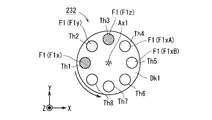
- FIG. 3 is a plan view showing a configuration example of the filter unit 232.
- the filter unit 232 shown in FIG. 3 is a rotary type.
- the filter unit 232 includes a circular disk Dk1, a rotation axis Ax1, a filter unit F1, and a motor unit M1 (FIG. 1) on a plane orthogonal to the lens optical axis (on the XY plane in the drawing). is doing.
- a plurality of through holes Th1, Th2, Th3, Th4, Th5, Th6, Th7, Th8 are provided in the circumferential direction along the outer edge.
- the plurality of through-holes Th1, Th2, Th3, Th4, Th5, Th6, Th7, Th8 are, for example, every 45 ° around the rotation axis Ax1 extending along the Z axis provided at the center of the disk Dk1. Is provided.
- a plurality of preset through holes for example, three through holes Th1, Th3, Th4.
- Three or more preset filter units F1 are attached.
- a filter portion F1x that allows light in the X wavelength range of the XYZ color system to pass is attached to the through hole Th1, and light in the Y wavelength range of the XYZ color system is allowed to pass through the through hole Th2.
- An example is shown in which a filter part F1y is attached, and a filter part F1z that allows light in the Z wavelength region of the XYZ color system to pass through is attached to the through hole Th3.
- the three or more filter portions F1 for example, instead of the three filter portions F1x, F1y, and F1z, red (R), green (G), and blue (B) filter portions, cyan (C), and magenta
- a filter unit for three colors such as (M) and yellow (Y) filter units may be employed.
- the three or more filter parts F1 for example, four or more filter parts F1 may be employed.
- the four or more filter units F1 for example, in addition to the three filter units F1x, F1y, and F1z related to the tristimulus values X, Y, and Z, one or more types of filter units related to the wavelength range of light different from them May be adopted.
- a filter that can approximately represent a spectrum of transmitted light (also referred to as a transmission spectrum) with a Gaussian function may be employed as the one or more types of filter units employed here. That is, the three or more filter units F1 may be a multiband filter having three or more filter units, for example.
- the disk Dk1 is rotated about the rotation axis Ax1 by the motor unit M1, for example, so that the type of the filter unit F1 disposed between the lens unit 231 and the detection unit 233 is switched.
- the disk Dk1 rotates 45 ° counterclockwise about the rotation axis Ax1, so that the filter unit F1 is in the order of the filter unit F1x, the filter unit F1y, and the filter unit F1z. Can be switched.
- the detection unit 233 outputs a signal corresponding to light incident through the filter unit 232.
- the detection unit 233 has, for example, a plurality of photoelectric conversion elements arranged two-dimensionally.
- the plurality of photoelectric conversion elements are arranged in a matrix, for example, to constitute an area sensor such as a CCD.
- the filter unit 232 adjusts the wavelength range of light received by the detection unit 233, and thus the detection unit 233 is configured by a monochrome area sensor or the like.
- the outer edge of the region that can be imaged by the detection unit 233 is indicated by a two-dot chain line.
- the detection unit 233 reflects the reflected light from the area (also referred to as a two-dimensional area) Am1 as a measurement target on the surface of the object 4 to be measured that enters the integrating sphere 21 through the opening H1, Reflected light from a region Ac1 located around the first opening Hp1 (also referred to as a peripheral region) Ac1 is received through the second opening Hp2.
- the detection unit 233 outputs signals corresponding to three or more light beams having different wavelength ranges.
- the output of signals corresponding to light of three or more mutually different wavelength ranges in the detection unit 233 includes output of signals corresponding to the tristimulus values X, Y, and Z.
- a value (also referred to as a characteristic value) related to the corresponding reflection characteristic can be easily obtained.
- the two-dimensional region Am1 is set so as not to include, for example, a region near the outer edge of the opening H1 in the surface of the DUT 4.
- a signal related to the reflected light from the two-dimensional region Am1 in which the influence of the shadow that can be generated on the surface of the measurement object 4 due to the edge of the first opening Hp1 and the decrease in the amount of irradiation light is reduced is obtained.
- the peripheral area Ac1 includes a correction area (also referred to as a correction area) P1. That is, the detection unit 233 receives the reflected light from the correction region P1 located around the first opening Hp1 in the integrating sphere 21 through the second opening Hp2.
- the correction area P1 for example, one or more correction reference plates (also referred to as correction reference plates) are arranged.
- the correction here refers to an error that occurs in the measurement value of the reflection characteristic on the surface of the object 4 to be measured by the illumination light in the integrating sphere 21 being modulated by the retro-reflecting light according to the surface color of the object 4 to be measured. It means to correct.
- the correction reference plate is, for example, a flat plate.
- FIG. 2 shows an example in which a red correction reference plate P1r, a green correction reference plate P1g, and a blue correction reference plate P1b are arranged as correction reference plates.
- the manner in which the correction reference plates are arranged in the correction region P1 is not limited to the manner in which the three-color correction reference plates P1r, P1g, and P1b are arranged.
- 4 and 5 are diagrams illustrating variations of the correction area P1.
- the correction reference plate may not be provided in the correction region P1.
- the inner wall surface 21si of the integrating sphere 21 is white, it is equivalent to a state where the white correction reference plate P1w is arranged in the correction region P1.
- a mode in which one or more correction reference plates are provided in the correction region P1 may be employed.
- a mode in which one or more correction reference plates include the white correction reference plate P1w may be employed.
- one or more correction reference plates may include four or more color correction reference plates.
- four or more correction reference plates include a red correction reference plate P1r, a green correction reference plate P1g, a blue correction reference plate P1b, a white correction reference plate P1w, and a yellow correction reference plate.
- An example is shown in which five color correction reference plates called the reference plate P1y are arranged.
- FIG. 6 is a block diagram illustrating a configuration example of the information processing unit 3.
- the information processing unit 3 includes an input unit 31, an output unit 32, a storage unit 33, an input / output (I / O) unit 34, interface (I / F) units 35, 36, and 37, and a control unit 38. Are connected via a bus 3b so that data can be transmitted and received.
- the input unit 31 is a part that inputs a signal in accordance with, for example, a user operation.
- the input unit 31 for example, an operation unit that inputs a signal according to the operation of various buttons by the user, a voice input unit that performs speech recognition according to a voice uttered by the user, and the like are adopted. obtain.
- the output unit 32 is a part that outputs various types of information in a manner that can be recognized by the user, for example.
- a display device or a projector that outputs various types of information in a manner that can be visually recognized by the user, and a speaker that outputs various types of information in a manner that allows the user to recognize each other may be employed.
- the storage unit 33 is a part that stores, for example, the program 3P and various information.
- a non-volatile storage medium such as a ROM may be employed.
- the I / O unit 34 is a part that receives the storage medium 39 and exchanges data between the storage medium 39 and the control unit 38.
- a USB port and a card reader can be employed.
- the storage medium 39 for example, a flash memory, an SD memory card, or the like can be adopted.
- the I / F units 35, 36, and 37 are portions that transmit and receive various signals and various data to and from portions other than the information processing unit 3 through communication lines or cables.
- the I / F unit 35 is connected to the illumination unit 22
- the I / F unit 36 is connected to the detection unit 233
- the I / F unit 37 is connected to the motor unit M1. ing.
- the control unit 38 is an electric circuit including a processor 38a and a memory 38b.
- a central processing unit CPU: Central Processing Unit
- a volatile memory such as RAM (Random Access Memory) or the like can be adopted as the memory 38b.
- the control unit 38 reads and executes the program 3P stored in the storage unit 33, thereby realizing various functions and various types of information processing in cooperation with the program 3P stored in the storage unit 33. Thereby, operation
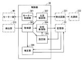
- FIG. 7 is a block diagram illustrating a functional configuration realized by the control unit 38 of the information processing unit 3.
- the information processing unit 3 implements, for example, a plurality of functional configurations by reading and executing the program 3P. That is, the information processing unit 3 has a plurality of functional configurations.
- the plurality of functional configurations include, for example, a motor control unit 381, a light source control unit 382, an acquisition unit 383, a storage control unit 384, a setting unit 385, a correction unit 386, and the like.
- the motor control unit 381 switches the type of the filter unit F1 disposed between the lens unit 231 and the detection unit 233 by controlling the rotation of the motor unit M1.
- one of the filter units F1x, F1y, and F1z of the tristimulus values X, Y, and Z is disposed between the lens unit 231 and the detection unit 233.
- the detection unit 233 can output a signal related to one wavelength region among the tristimulus values X, Y, and Z.
- the filter unit F1x of the tristimulus value X is disposed between the lens unit 231 and the detection unit 233, so that the detection unit 233 outputs a signal related to the wavelength range of the tristimulus value X. obtain.
- the filter unit F1y having the tristimulus value Y is disposed between the lens unit 231 and the detection unit 233, so that the detection unit 233 can output a signal related to the wavelength range of the tristimulus value Y.
- the filter unit F1z of the tristimulus value Z is disposed between the lens unit 231 and the detection unit 233, so that the detection unit 233 can output a signal related to the wavelength range of the tristimulus value Z.
- the light source control unit 382 controls irradiation of illumination light to the inner wall surface 21si of the integrating sphere 21 by the illumination unit 22. Specifically, the light source control unit 382 controls the light emission of the light source unit 222 via the light emitting circuit 221.
- the acquisition unit 383 Based on the signal output from the detection unit 233, the acquisition unit 383 acquires a two-dimensional distribution (also referred to as a two-dimensional distribution) of light reflection characteristics in the two-dimensional region Am1 of the sample 4sm as the object to be measured 4. .
- the acquisition unit 383 After the signal output from the detection unit 233 is corrected for linearity related to the sensor output of the detection unit 233, the acquisition unit 383 generates a two-dimensional distribution of light reflection characteristics.
- the two-dimensional distribution of the light reflection characteristic may be acquired directly from the signal output from the detection unit 233.
- the light reflection characteristics in the two-dimensional area Am1 are, for example, in accordance with the color in the two-dimensional area Am1.
- the acquisition unit 383 acquires image data indicating a two-dimensional distribution of light reflection characteristics in the two-dimensional region Am1 for the wavelength range of light associated with each of the tristimulus values X, Y, and Z. Can be done.
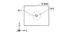
- FIG. 8 is a view showing an example of the surface of a sample 4 sm as the DUT 4.
- FIG. 8 shows an aspect in which the outer edge of the region Ar0 corresponding to the opening H1 is indicated by a two-dot chain line, and the region corresponding to the two-dimensional region Am1 includes the region Ar1 different from the surrounding color. .
- the acquisition unit 383 acquires a characteristic value related to the light reflection characteristic in the correction region P1 based on the signal output from the detection unit 233.
- the light in the correction region P1 is output in accordance with a signal output from the detection unit 233 when the calibration white plate as the reference object 4st is disposed so as to cover the measurement opening H1.
- a characteristic value related to the reflection characteristic (also referred to as a first characteristic value) is acquired.
- a characteristic value also referred to as a second characteristic value
- the two-dimensional distribution of the light reflection characteristic in the two-dimensional area Am1 and the second characteristic value can be acquired under the same illumination condition.
- each of the first characteristic value and the second characteristic value includes, for example, one or more characteristic values relating to the light reflection characteristic of the correction reference plate P1, the surface of the sample 4sm as the object 4 to be measured Thus, the measurement accuracy of the light reflection characteristics can be improved.
- the acquisition unit 383 can acquire the characteristic value related to the reflection characteristic of the light in the correction region P1 for the light in the wavelength range related to each of the tristimulus values X, Y, and Z.
- the characteristic value for example, a representative value for each color portion of the image data indicating the two-dimensional distribution of the light reflection characteristic in the correction region P1 may be employed.
- the representative value for example, a statistical value such as an average value or a mode value may be employed.
- an average value for each color portion in the image data indicating the two-dimensional distribution of the light reflection characteristic in the correction region P1 is employed as the first characteristic value and the second characteristic value.
- the storage control unit 384 acquires image data indicating the two-dimensional distribution of the light reflection characteristics in the two-dimensional area Am1 acquired by the acquisition unit 383, the first characteristic value and the first characteristic value related to the light reflection characteristics in the correction area P1. Two characteristic values are stored in the storage unit 33.
- the setting unit 385 sets a conversion rule that can convert the second characteristic value to the first characteristic value based on the first characteristic value and the second characteristic value acquired by the acquisition unit 383.
- the correction unit 386 converts the sample 4sm acquired by the acquisition unit 383 in accordance with a signal output from the detection unit 233 when the sample 4sm is arranged so as to cover the measurement opening H1 by conversion based on the conversion rule.
- the two-dimensional distribution of the light reflection characteristics in the two-dimensional area Am1 is corrected.
- the image data indicating the two-dimensional distribution of the light reflection characteristics in the two-dimensional region Am1 on the surface of the sample 4sm as the object to be measured 4 can be corrected by conversion based on the conversion rule.
- the conversion rule is defined by, for example, a conversion formula.
- the form of this conversion formula differs depending on the mode of the correction region P1 and the filter unit 232, for example.
- the relationship of Expression (1) is established between the first characteristic value Vx and the second characteristic value Vx ′, and the wavelength range related to the tristimulus value Y
- the relationship of the expression (2) is established between the first characteristic value Vy and the second characteristic value Vy ′, and the first characteristic value Vz and the first characteristic value for the light in the wavelength range related to the tristimulus value Z are established.
- the relationship of the formula (3) is established between the two characteristic values Vz ′.
- k, l, and m are coefficients.
- Vx k ⁇ Vx ′ (1)
- Vy 1 ⁇ Vy ′ (2)
- Vz m ⁇ Vz ′ (3).
- the pixel value Vx ′ ( ⁇ of image data indicating the two-dimensional distribution of the reflection characteristics of the light in the two-dimensional region Am1 of the sample 4sm with respect to the light in the wavelength region related to each of the tristimulus values X, Y, and Z. ) 'Vy' ( ⁇ ), Vz '( ⁇ ) and the pixel values Vx ( ⁇ ), Vy ( ⁇ ), Vz ( ⁇ ) of the corrected image data based on the conversion formula, The relationship from 4) to (6) is established.
- ⁇ represents a wavelength.
- Vx ( ⁇ ) k ⁇ Vx ′ ( ⁇ ) (4)
- Vy ( ⁇ ) 1 ⁇ Vy ′ ( ⁇ ) (5)
- Vz ( ⁇ ) m ⁇ Vz ′ ( ⁇ ) (6).
- the first characteristic value Vxr and the second characteristic value Vxr ′ related to the light in the wavelength range related to the tristimulus value X, and the light in the wavelength range related to the tristimulus value Y are represented by the relations (7) to (9). Is established.
- k1, k2, k3, l1, l2, l3, m1, m2, and m3 are coefficients.
- Vxr k1 * Vxr '+ k2 * Vyr' + k3 * Vzr '(7)
- Vyr l1 ⁇ Vxr ′ + l2 ⁇ Vyr ′ + l3 ⁇ Vzr ′ (8)
- Vzr m1 * Vxr '+ m2 * Vyr' + m3 * Vzr '(9).
- the first characteristic value Vxg and the second characteristic value Vxg ′ related to the light in the wavelength range related to the tristimulus value X, and the second related to the light in the wavelength range related to the tristimulus value Y have the relations of equations (10) to (12). To establish.
- Vxg k1 * Vxg '+ k2 * Vyg' + k3 * Vzg '(10)
- Vyg l1 ⁇ Vxg ′ + l2 ⁇ Vyg ′ + l3 ⁇ Vzg ′ (11)
- Vzg m1 * Vxg '+ m2 * Vyg' + m3 * Vzg '(12).
- the first characteristic value Vxb and the second characteristic value Vxb ′ relating to the light in the wavelength range related to the tristimulus value X and the second characteristic value relating to the light in the wavelength range relating to the tristimulus value Y are obtained.
- the first characteristic value Vyb, the second characteristic value Vyb ′, and the first characteristic value Vzb and the second characteristic value Vzb ′ related to the light in the wavelength range related to the tristimulus value Z have the relations of equations (13) to (15).
- Vxb k1 * Vxb '+ k2 * Vyb' + k3 * Vzb '(13)
- Vyb l1 ⁇ Vxb ′ + l2 ⁇ Vyb ′ + l3 ⁇ Vzb ′ (14)
- Vzb m1 * Vxb '+ m2 * Vyb' + m3 * Vzb '(15).
- the pixel value Vx ′ ( ⁇ of image data indicating the two-dimensional distribution of the reflection characteristics of the light in the two-dimensional region Am1 of the sample 4sm with respect to the light in the wavelength region related to each of the tristimulus values X, Y, and Z. ), Vy ′ ( ⁇ ), Vz ′ ( ⁇ ) and the pixel values Vx ( ⁇ ), Vy ( ⁇ ), Vz ( ⁇ ) of the corrected image data based on the conversion formula, 16) to (18) are established.
- ⁇ represents a wavelength.
- Vx ( ⁇ ) k1 ⁇ Vx ′ ( ⁇ ) + k2 ⁇ Vy ′ ( ⁇ ) + k3 ⁇ Vz ′ ( ⁇ ) (16)
- Vy ( ⁇ ) l1 ⁇ Vx ′ ( ⁇ ) + l2 ⁇ Vy ′ ( ⁇ ) + l3 ⁇ Vz ′ ( ⁇ ) (17)
- Vz ( ⁇ ) m1 ⁇ Vx ′ ( ⁇ ) + m2 ⁇ Vy ′ ( ⁇ ) + m3 ⁇ Vz ′ ( ⁇ ) (18)
- the five color correction reference plates for example, a red correction reference plate P1r, a green correction reference plate P1g, a blue correction reference plate P1b, a white correction reference plate P1w, and a yellow correction reference plate.
- a plate P1y is employed.
- the first characteristic value Vxr and the second characteristic value Vxr ′ related to the light in the wavelength range related to the tristimulus value X, and the light in the wavelength range related to the tristimulus value Y The first characteristic value Vyr and the second characteristic value Vyr ′, the first characteristic value Vzr and the second characteristic value Vzr ′ related to the light in the wavelength range related to the tristimulus value Z, the first related to the light in the wavelength range of the transmission spectrum A
- the relationship of Expressions (19) to (23) is established between the characteristic value Var, the second characteristic value Var ′, and the first characteristic value Vbr and the second characteristic value Vbr ′ relating to light in the wavelength region of the transmission spectrum B.
- k1, k2, k3, k4, k5, l1, l2, l3, l4, l5, m1, m2, m3, m4, m5, n1, n2, n3, n4, n5, o1, o2, o3, o4 , O5 is a coefficient.
- Vxr k1 * Vxr '+ k2 * Vyr' + k3 * Vzr '+ k4 * Var' + k5 * Vbr '(19)
- Vyr l1 ⁇ Vxr ′ + l2 ⁇ Vyr ′ + l3 ⁇ Vzr ′ + l4 ⁇ Var ′ + l5 ⁇ Vbr ′
- Vzr m1 ⁇ Vxr ′ + m2 ⁇ Vyr ′ + m3 ⁇ Vzr ′ + m4 ⁇ Var ′ + m5 ⁇ Vbr ′
- Var n1 ⁇ Vxr ′ + n2 ⁇ Vyr ′ + n3 ⁇ Vzr ′ + n4 ⁇ Var ′ + n5 ⁇ Vbr ′
- Vbr o1 * Vxr '+ o2 * Vyr' + o3 * Vzr
- the first characteristic value Vxg and the second characteristic value Vxg ′ related to the light in the wavelength range related to the tristimulus value X, and the second related to the light in the wavelength range related to the tristimulus value Y are related to the first characteristic value Vxg and the second characteristic value Vxg ′ related to the light in the wavelength range related to the tristimulus value X, and the second related to the light in the wavelength range related to the tristimulus value Y.
- the relationship of Expressions (24) to (28) is established between the value Vag, the second characteristic value Vag ′, and the first characteristic value Vbg and the second characteristic value Vbg ′ relating to light in the wavelength band of the transmission spectrum B.
- Vxg k1 * Vxg '+ k2 * Vyg' + k3 * Vzg '+ k4 * Vag' + k5 * Vbg '(24)
- Vyg l1 ⁇ Vxg ′ + l2 ⁇ Vyg ′ + l3 ⁇ Vzg ′ + l4 ⁇ Vag ′ + l5 ⁇ Vbg ′
- Vzg m1 * Vxg '+ m2 * Vyg' + m3 * Vzg '+ m4 * Vag' + m5 * Vbg '(26)
- Vag n1 ⁇ Vxg ′ + n2 ⁇ Vyg ′ + n3 ⁇ Vzg ′ + n4 ⁇ Vag ′ + n5 ⁇ Vbg ′
- Vbg o1 * Vxg '+ o2 * Vyg' + o3 * Vzg '
- the first characteristic value Vxb and the second characteristic value Vxb ′ relating to the light in the wavelength range related to the tristimulus value X and the second characteristic value relating to the light in the wavelength range relating to the tristimulus value Y are obtained.
- the relationship of Expressions (29) to (33) is established between the value Vab, the second characteristic value Vab ′, and the first characteristic value Vbb and the second characteristic value Vbb ′ relating to light in the wavelength region of the transmission spectrum B.
- Vxb k1 * Vxb '+ k2 * Vyb' + k3 * Vzb '+ k4 * Vab' + k5 * Vbb '(29)
- Vyb l1 ⁇ Vxb ′ + l2 ⁇ Vyb ′ + l3 ⁇ Vzb ′ + l4 ⁇ Vab ′ + l5 ⁇ Vbb ′
- Vzb m1 ⁇ Vxb ′ + m2 ⁇ Vyb ′ + m3 ⁇ Vzb ′ + m4 ⁇ Vab ′ + m5 ⁇ Vbb ′ (31)
- Vab n1 ⁇ Vxb ′ + n2 ⁇ Vyb ′ + n3 ⁇ Vzb ′ + n4 ⁇ Vab ′ + n5 ⁇ Vbb ′ (32)
- Vbb o1 * Vxb '+ o2 * Vyb' +
- the first characteristic value Vxw and the second characteristic value Vxw ′ related to the light in the wavelength range related to the tristimulus value X, and the second related to the light in the wavelength range related to the tristimulus value Y are related to the white correction reference plate P1w.
- the relationship of Expressions (34) to (38) is established between the value Vaw, the second characteristic value Vaw ′, and the first characteristic value Vbw and the second characteristic value Vbw ′ relating to light in the wavelength region of the transmission spectrum B.
- Vxw k1 ⁇ Vxw ′ + k2 ⁇ Vyw ′ + k3 ⁇ Vzw ′ + k4 ⁇ Vaw ′ + k5 ⁇ Vbw ′ (34)
- Vyw l1 ⁇ Vxw ′ + l2 ⁇ Vyw ′ + l3 ⁇ Vzw ′ + l4 ⁇ Vaw ′ + l5 ⁇ Vbw ′ (35)
- Vzw m1 ⁇ Vxw ′ + m2 ⁇ Vyw ′ + m3 ⁇ Vzw ′ + m4 ⁇ Vaw ′ + m5 ⁇ Vbw ′ (36)
- Vaw n1 ⁇ Vxw ′ + n2 ⁇ Vyw ′ + n3 ⁇ Vzw ′ + n4 ⁇ Vaw ′ + n5 ⁇ Vbw ′ (37)
- Vbw o1 * Vxw '+ o
- the first characteristic value Vxy and the second characteristic value Vxy ′ related to the light in the wavelength range related to the tristimulus value X, and the second related to the light in the wavelength range related to the tristimulus value Y are related to the yellow correction reference plate P1y.
- Vxy k1 * Vxy '+ k2 * Vyy' + k3 * Vzy '+ k4 * Vay' + k5 * Vby '(39)
- Vyy l1 ⁇ Vxy ′ + l2 ⁇ Vyy ′ + l3 ⁇ Vzy ′ + l4 ⁇ Vay ′ + l5 ⁇ Vby ′ (40)
- Vzy m1 ⁇ Vxy ′ + m2 ⁇ Vyy ′ + m3 ⁇ Vzy ′ + m4 ⁇ Vay ′ + m5 ⁇ Vby ′ (41)
- Vay n1 ⁇ Vxy ′ + n2 ⁇ Vyy ′ + n3 ⁇ Vzy ′ + n4 ⁇ Vay ′ + n5 ⁇ Vby ′ (42)
- Vby o1 * Vxy '+ o2 * Vyy' + o3 * Vzy '
- Vx ( ⁇ ) k1 ⁇ Vx ′ ( ⁇ ) + k2 ⁇ Vy ′ ( ⁇ ) + k3 ⁇ Vz ′ ( ⁇ ) + k4 ⁇ Va ′ ( ⁇ ) + k5 ⁇ Vb ′ ( ⁇ ) (44)
- Vy ( ⁇ ) l1 ⁇ Vx ′ ( ⁇ ) + l2 ⁇ Vy ′ ( ⁇ ) + l3 ⁇ Vz ′ ( ⁇ ) + l4 ⁇ Va ′ ( ⁇ ) + l5 ⁇ Vb ′ ( ⁇ ) (45)
- Vz ( ⁇ ) m1 ⁇ Vx ′ ( ⁇ ) + m2 ⁇ Vy ′ ( ⁇ ) + m3 ⁇ Vz ′ ( ⁇ ) + m4 ⁇ Va ′ ( ⁇ ) + m5 ⁇ Vb ′ ( ⁇ ) (46)
- Va ( ⁇ ) n1 ⁇ Vx ′ ( ⁇ ) + n2 ⁇ Vy ′ ( ⁇ ) + n3 ⁇ Vz
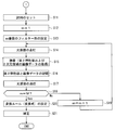
- FIG. 9 and FIG. 10 are diagrams illustrating an example of an operation flow related to color measurement processing in the reflection characteristic measurement system 1. This operation flow is started, for example, by turning on the power of the reflection characteristic measurement system 1 according to the user's operation, and proceeds to step S1 in FIG.
- step S1 a white plate for calibration as the reference object 4st is set to the reflection characteristic measuring unit 2.
- the calibration white plate as the reference object 4st is arranged so as to cover the measurement opening H1.
- step S2 the control unit 38 sets a numerical value m to 1 to identify the number of the filter unit F1 used by the filter unit F1.
- the numerical value m can be sequentially set to a natural number from 1 to a natural number M of 3 or more.
- step S3 the mth filter unit F1 is set in the filter unit 232.
- the mth filter unit F1 is disposed between the lens unit 231 and the detection unit 233.
- step S4 the light source unit 222 is turned on.
- the light source unit 222 is turned on under the control of the light source control unit 382 in accordance with a signal input from the input unit 31 according to the user's operation.
- step S5 imaging by the detection unit 233 is performed.
- the reflected light from the light enters the detection unit 233 via the lens unit 231 and the filter unit 232.
- the acquisition unit 383 can acquire the first characteristic value related to the reflection characteristic of the light in the correction region P1 for the light in the wavelength region related to the m-th filter unit F1.
- the first characteristic value can be acquired for each correction reference plate.
- step S6 the storage control unit 384 stores the first characteristic value acquired in step S5 in the storage unit 33.
- step S7 the light source unit 222 is turned off under the control of the light source control unit 382.
- step S8 the control unit 38 determines whether or not the numerical value m has reached the number M of the filter units F1. If the numerical value m has not reached M, the process proceeds to step S9. If the numerical value m has reached M, the process proceeds to step S11 in FIG.
- step S9 the control unit 38 increments the numerical value m by one and returns to step S4. That is, the processing from step S4 to step S9 is repeated until the first characteristic value is acquired for the M filter units F1.
- step S11 the sample 4sm is set to the reflection characteristic measurement unit 2.
- the sample 4sm is disposed so as to cover the measurement opening H1.
- step S12 the control unit 38 sets a numerical value m to 1 to identify the number of the filter unit F1 to be used.
- step S13 the mth filter unit F1 is set in the filter unit 232.
- the mth filter unit F1 is disposed between the lens unit 231 and the detection unit 233.
- step S14 the light source unit 222 is turned on.
- the light source unit 222 is turned on under the control of the light source control unit 382 in accordance with a signal input from the input unit 31 according to the user's operation.
- step S15 imaging by the detection unit 233 is performed.
- the reflected light from the two-dimensional area Am1 of the sample 4sm that enters the integrating sphere 21 through the opening H1 and the peripheral area Ac1 positioned around the first opening Hp1 in the integrating sphere 21.
- the reflected light enters the detection unit 233 via the lens unit 231 and the filter unit 232.
- the acquisition unit 383 causes the second characteristic value related to the reflection characteristic of the light in the correction region P1 and the reflection of the light in the two-dimensional region Am1 of the sample 4sm with respect to the light in the wavelength region related to the mth filter unit F1.
- Image data showing a two-dimensional distribution of characteristics can be obtained.
- the second characteristic value can be acquired for each correction reference plate.
- step S16 the storage control unit 384 stores the second characteristic value acquired in step S15 and the image data related to the two-dimensional area Am1 of the sample 4sm in the storage unit 33.
- step S17 the light source unit 222 is turned off under the control of the light source control unit 382.
- step S18 the control unit 38 determines whether or not the numerical value m has reached the number M of the filter units F1. If the numerical value m has not reached M, the process proceeds to step S19. If the numerical value m has reached M, the process proceeds to step S20.
- step S19 the numerical value m is incremented by 1, and the process returns to step S14. That is, for the M filter units F1, the processing from step S14 to step S19 is repeated until image data relating to the second characteristic value and the two-dimensional area Am1 of the sample 4sm is acquired.
- a conversion rule is set by the setting unit 385.
- the conversion rule is set based on the first characteristic value obtained in step S5 and the second characteristic value obtained in step S15. Further, for example, the first characteristic value and the second characteristic value are applied to the relational expression corresponding to the number of filter portions F1 in the filter unit 232 and the correction reference plate provided in the correction region P1. A coefficient is calculated. Thereby, a conversion formula as a conversion rule including the coefficient can be set. And by such a process, whenever the sample 4sm is set, the conversion formula as a conversion rule according to the surface color of the sample 4sm can be set.
- step S21 the correction unit 386 corrects the two-dimensional distribution of the light reflection characteristics in the two-dimensional region Am1 related to the sample 4sm obtained in step S15 by the conversion based on the conversion rule set in step S20.
- the image data indicating the two-dimensional distribution of the light reflection characteristics in the two-dimensional region Am1 on the surface of the sample 4sm as the DUT 4 can be corrected by conversion based on the conversion formula as the conversion rule.
- the present invention is not limited to this.
- a calibration white plate as the reference object 4st may be set and the first characteristic value may be acquired.
- a mode in which the first characteristic value is acquired by setting the calibration white plate as the reference object 4st at the timing before the start of the measurement for the plurality of samples 4sm is conceivable. Thereby, the load of measurement and calculation can be reduced.
- the first characteristic value is acquired by setting the calibration white plate as the reference object 4st at the timing after measurement of the plurality of samples 4sm.
- the image data relating to the plurality of samples 4sm can be collectively corrected.
- the two-dimensional distribution of the light reflection characteristics in the two-dimensional area Am1 related to the sample 4sm is corrected by the conversion rule, and then further corrected by the white calibration coefficient, so that the sample 4sm is corrected.
- a two-dimensional distribution of the light reflection characteristics after correction may be acquired.
- the integrating sphere 21 has an inner diameter of 100 mm, the diameter of the opening H1 is set to 40 mm, and the diameter of the two-dimensional region Am1 is set to 35 mm.
- the light source unit 222 employs an A light source that emits light so that the color temperature is 2854K.
- the A light source can be realized by a tungsten light bulb (also called an incandescent bulb).
- the light receiving sensitivity in the light receiving unit 23 is such that an ideal color matching function of XYZ corresponds to a 10 ° field of view.
- the value (it is also called evaluation value) Lab which shows the object color about 13 types of to-be-measured objects 4, the true value on condition that the illumination light in the integrating sphere 21 is not modulated by recursive illumination light (both true value) Say) was calculated. Further, with respect to the object color evaluation value Lab for the 12 types of samples 4sm, a measurement value (also referred to as an uncorrected value) under the condition that the illumination light in the integrating sphere 21 is modulated by the recursive illumination light, and the measurement value A value (correction value) obtained by correcting according to the conversion rule was calculated.
- the object color evaluation value Lab was calculated by conversion from the tristimulus values X, Y, and Z obtained by the detection unit 233.
- the evaluation value ⁇ Lab indicating the error in the measurement result caused by the recursive illumination light
- the difference between the true value and the uncorrected value and the difference between the true value and the corrected value were calculated for 12 types of samples 4sm.
- the evaluation value ⁇ Lab is smaller, it means that the measurement accuracy of the light reflection characteristic is improved by the correction based on the conversion rule.
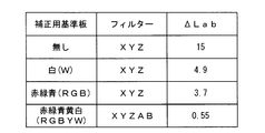
- FIG. 11 is a diagram showing the relationship between the correction condition under simulation and the evaluation value ⁇ Lab. As shown in FIG. 11, when three filter portions F1x, F1y, and F1z corresponding to the tristimulus values X, Y, and Z are used, the following three types of conditions [i] to [iii] are used. A simulation was performed.
- FIG. 11 shows the relationship between the correction condition in the simulation and the evaluation value ⁇ Lab.
- FIG. 11 shows the maximum value of the evaluation values ⁇ Lab calculated for 12 types of samples 4sm for each correction condition.
- the evaluation value ⁇ Lab was about 15 under the condition where no correction was performed.
- the evaluation value ⁇ Lab is about 4.9 under the correction condition [ii]. For this reason, it was found that the evaluation value ⁇ Lab is greatly improved by the correction using the conversion rule.
- the evaluation value ⁇ Lab was about 3.7, and the evaluation value ⁇ Lab was greatly improved by the correction using the conversion rule. For this reason, by using the three-color correction reference plates P1r, P1g, and P1b, it is possible to correct colors existing in a wider color space, and the light reflection characteristics on the surface of the sample 4 sm are highly accurate. It was estimated that it could be measured.
- the evaluation value ⁇ Lab is about 0.55 under the correction condition [iv].
- the types of filter portions F1 increase and the yellow (Y) correction reference plate P1y and the white (W) correction reference plate P1w are employed, the evaluation value ⁇ Lab is corrected using the conversion rule. It has been found that this can be further improved.
- the use of the five color correction reference plates including yellow and white makes it possible to correct colors existing in a wider color space, and the light reflection characteristics on the surface of the sample 4 sm are higher. It was estimated that it could be measured accurately.
- the acquisition unit according to the signal output from the detection unit 233 when the reference object 4st is arranged so as to cover the measurement opening H1.
- the first characteristic value related to the light reflection characteristic in the correction region P1 is acquired.
- the acquisition unit 383 performs a second operation related to the light reflection characteristic in the correction region P1 according to a signal output from the detection unit 233.
- a characteristic value is obtained.
- the setting unit 385 sets a conversion rule that can convert the second characteristic value into the first characteristic value based on the first characteristic value and the second characteristic value.
- the correction unit 386 corrects the two-dimensional distribution of the reflection characteristics related to the two-dimensional region Am1 on the surface of the sample 4sm acquired by the acquisition unit 383 by conversion based on the conversion rule. Thereby, the influence by the modulation
- the two-dimensional area Am1 as the measurement target area in the sample 4sm is expanded by expanding the measurement opening H1 to some extent. obtain.
- the number of the detection units 233 is one, high-precision measurement of light reflection characteristics can be realized.
- a conversion formula as a conversion rule corresponding to the surface color of the sample 4sm for each sample 4sm, even if there is a slight deviation in the modulation of the illumination light by the recursive illumination light, The influence of modulation can be suppressed.
- the integrating sphere 21 is described only as a sphere.
- a configuration in which a spherical portion forming the integrating sphere 21 is formed by two or more portions may be employed.
- the first modified example having such a configuration will be described with a specific example.
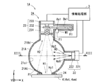
- FIG. 12 is a diagram illustrating a schematic configuration of the reflection characteristic measurement system 1A according to the first modification.
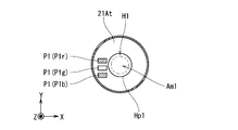
- FIG. 13 is a diagram illustrating a state in which the bottom of the integrating sphere 21A is viewed from the inside. Specifically, FIG. 13 is a diagram showing an XY cross section at a position indicated by a one-dot chain line XIII-XIII in FIG.
- the reflection characteristic measurement system 1A is based on the reflection characteristic measurement system 1 according to the above-described embodiment, and the reflection characteristic measurement unit 2 is changed from the integrating sphere 21 to the integrating sphere 21A. Part 2A is replaced.
- the integrating sphere 21A has a main body portion 21Bd and a mounting portion 21At.
- the main body 21Bd includes the second opening Hp2.
- the attachment portion 21At is attached to the main body portion 21Bd and includes the first opening Hp1 and the correction region P1. If such a configuration is adopted, it becomes easy to manufacture a portion provided with the correction reference plate. As a result, the integrating sphere 21 can be easily manufactured.
- FIG. 14 is a diagram illustrating a schematic configuration of the attachment portion 21At that is not attached to the main body portion 21Bd.
- the attachment portion 21At may have a configuration that can be attached to and detached from the main body portion 21Bd, or a configuration that can only be attached to the main body portion 21Bd by bonding or the like. May be.
- worn by rotating in the state engaged mutually for example may be employ
- FIG. 15 is a diagram illustrating a schematic configuration of a reflection characteristic measurement system 1B according to the second modification.
- FIG. 16 is a diagram illustrating a state in which the bottom of the integrating sphere 21B is viewed from the inside. Specifically, FIG. 16 is a diagram showing an XY cross section at a position indicated by a one-dot chain line XVI-XVI in FIG.
- the reflection characteristic measurement system 1B is based on the reflection characteristic measurement system 1A according to the first modification, and the reflection characteristic measurement unit 2A is changed from the integrating sphere 21A to the integrating sphere 21B.
- the measurement unit 2B is replaced.
- the integrating sphere 21B has a main body portion 21Bd and a mounting portion 21AtB.
- the attachment portion 21AtB is attached to the main body portion 21Bd and includes the first opening Hp1 and the correction region P1.
- the attachment portion 21AtB is provided with three types of correction reference plates P1 (P1r, P1g, P1b) as one or more correction reference plates.
- Each correction reference plate is arranged toward the internal space of the integrating sphere 21B and has one main surface having a virtual normal passing through the detection opening H2.
- the one main surface may be a flat surface, for example.
- virtual normals are drawn with thin arrows.
- correction reference plates P1r, P1g, and P1b are provided.
- one or more correction reference plates may be provided. At least one correction reference plate among the one or more correction reference plates is disposed toward the internal space of the integrating sphere and has a virtual normal line passing through the detection opening H2. If the main surface is provided, the light reflection characteristic on the surface of the sample 4 sm can be measured with higher accuracy.
- the detection unit 233 outputs a signal corresponding to the light incident through the filter unit 232, but the present invention is not limited to this.
- the detection unit 233 may be a color area sensor having a three-plate type (3CCD type) configuration, or a color area sensor having a single-plate type configuration. Also good. That is, the detection unit 233 only needs to output signals corresponding to three or more light beams in different wavelength ranges.
- a filter related to the three colors R, G, and B or a filter related to the three colors C, M, and Y Filters relating to the three wavelength bands of light may be employed.
- the photoelectric conversion element directly outputs signals respectively corresponding to light of three mutually different wavelength ranges corresponding to the tristimulus values X, Y, and Z. Although it output, it is not restricted to this.
- the photoelectric conversion element after the photoelectric conversion element once obtains signals corresponding respectively to light in three or more wavelength ranges different from the tristimulus values X, Y, and Z such as R, G, and B, these Based on the signal, a configuration may be adopted in which signals respectively corresponding to light of three mutually different wavelength ranges corresponding to the tristimulus values X, Y, and Z are output.
- the stimulus value X of the three stimulus values X, Y, and Z may be obtained by being decomposed into values X1 and X2, for example. In this case, for example, the value X1 can be calculated from the stimulus value Z.
- the detection unit 233 is an area sensor, but is not limited thereto.
- the detection unit 233 has a configuration in which a plurality of photoelectric conversion elements are arranged in the first direction, and the detection unit 233 is scanned in the second direction intersecting the first direction.
- a configuration that performs substantially the same function as the area sensor may be employed.
- a first line sensor provided with a filter corresponding to the tristimulus value X
- a second line sensor provided with a filter corresponding to the tristimulus value Y
- a filter corresponding to the tristimulus value Z A sensor having three line sensors composed of a third line sensor in which is arranged may be employed.
- the calibration white plate is used as the calibration reference object 4st.
- the present invention is not limited to this.
- an object of another color different from white may be employed as the reference object 4st for calibration.
- the two-dimensional distribution of the reflection characteristic corrected by the conversion based on the conversion rule indicates a value under illumination affected by the retro-illumination light of the calibration reference object 4st.
- the conversion rule is defined in the form of a conversion formula, but the present invention is not limited to this.
- the conversion rule may be defined by a table (also referred to as a conversion table) in which values obtained in advance by actual measurement or simulation are described.
- the numerical value related to the object color is adopted as the reflection characteristic, but the present invention is not limited to this, and the reflectance of light in a specific wavelength region may be adopted.
- the present invention includes, for example, reflection characteristic measurement systems according to the following second to seventh aspects.
- a reflection characteristic measurement system is the reflection characteristic measurement system according to the first aspect, wherein outputs of signals respectively corresponding to light in the three or more different wavelength ranges in the detection unit are output. 3. Includes output of signals corresponding to tristimulus values.
- the value relating to the reflection characteristic of light corresponding to the color matching function can be easily obtained.
- a reflection characteristic measurement system is the reflection characteristic measurement system according to the first or second aspect, further comprising one or more correction reference plates arranged in the correction region.
- the first characteristic value and the second characteristic value each include characteristic values relating to light reflection characteristics of the one or more correction reference plates.
- the reflection characteristic measurement system is the reflection characteristic measurement system according to the third aspect, wherein the one or more correction reference plates include a white correction reference plate.
- the reflection characteristic measurement system can improve the measurement accuracy of the light reflection characteristic on the surface of the sample.
- a reflection characteristic measurement system is the reflection characteristic measurement system according to the third or fourth aspect, wherein the one or more correction reference plates are red, green and blue correction reference plates. including.
- the reflection characteristic measurement system it is possible to correct a color existing in a wider color space, so that the reflection characteristic of light on the surface of the sample can be measured with high accuracy.
- a reflection characteristic measurement system is the reflection characteristic measurement system according to any one of the third to fifth aspects, wherein at least one of the one or more correction reference plates is used for correction.
- a reference plate is disposed facing the internal space of the integrating sphere and has a principal surface having a virtual normal passing through the detection opening.
- the reflection characteristic measurement system since the influence of the reflection of the inner wall of the integrating sphere is reduced in the detection result of one main surface of the correction reference plate, the reflection characteristic of light on the surface of the sample is reduced. Can be measured with higher accuracy.
- a reflection characteristic measurement system is the reflection characteristic measurement system according to any one of the third to sixth aspects, wherein the integrating sphere includes a main body including the second opening, And an attachment portion that is attached to the main body portion and includes the first opening and the correction region.
- the manufacture of the integrating sphere can be facilitated because the manufacture of the portion provided with the correction reference plate is facilitated.
Landscapes
- Physics & Mathematics (AREA)
- Spectroscopy & Molecular Physics (AREA)
- General Physics & Mathematics (AREA)
- Life Sciences & Earth Sciences (AREA)
- Theoretical Computer Science (AREA)
- Health & Medical Sciences (AREA)
- Mathematical Physics (AREA)
- Chemical & Material Sciences (AREA)
- Analytical Chemistry (AREA)
- Biochemistry (AREA)
- General Health & Medical Sciences (AREA)
- Engineering & Computer Science (AREA)
- Immunology (AREA)
- Pathology (AREA)
- Spectrometry And Color Measurement (AREA)
Abstract
試料の表面における光の反射特性が高精度に測定され得る小型の反射特性測定システムを提供することを目的とする。該目標を達成するために、積分球の測定用の開口に基準物体が覆うように配されている際に検出部から出力される信号に応じて取得される、積分球内の第1開口部の周囲に位置する補正用領域における光の反射特性に係る第1特性値と、測定用の開口に試料が覆うように配されている際に検出部から出力される信号に応じて取得される、補正用領域における光の反射特性に係る第2特性値とに基づいて、該第2特性値を第1特性値に変換することが可能な変換ルールが設定される。変換ルールに基づく変換によって、測定用の開口に試料が覆うように配されている際に検出部から出力される信号に応じて取得された試料の2次元領域における反射特性の2次元の分布が補正される。
Description
本発明は、試料の表面における光の反射特性を測定するシステムに関する。
積分球の開口部に配された試料を測色の対象物として該積分球を用いて照明し、該試料からの反射光を受光して、試料の表面色(具体的には、物体色)を測定する測色装置がある(例えば、特許文献1)。
この測色装置では、積分球における測定用の開口部(測定開口部とも言う)の大きさは、試料の種類および大きさ等に応じて適宜決定される。そして、試料のうちの測定開口部に配された部分を面状の測定の対象としての一領域(被測定領域とも言う)とした測定(平均値測定、スポット測定)が行われる。ここで、一般にポータブルまたはハンディタイプの測色装置では、測定開口部の径は、積分球の大きさに応じて3mmから20mm程度に設定されている。これは、積分球の直径に対して、物体色の測定に影響が生じ難い範囲内で、測定開口部の開口径が設定されることによる。
また、測色装置において、所定の大きさの被測定領域内における色彩の2次元分布が測定され得るのであれば、被測定領域の選択、離れた複数箇所の同時測定および細長い領域の測定等によって、被測定領域における色むらおよび柄物等の複雑な形状が測定され得る。このような測定は、従来の測色装置のように、試料の表面のうちの円形の測定開口部に配された円形の被測定領域の色の平均値が測定される態様では、実現され得なかった。
ところで、色彩の2次元分布が測定され得る測色装置としては、机上等に設置される大型のタイプのものに限られず、小型かつ軽量で、手で持ち運ぶことが可能な携帯式のタイプのものが考えられる。
ただ、試料の被測定領域の大きさがある程度確保されなければ、色彩の2次元分布を捉えることが容易でない。さらに、積分球等を使って、試料をあらゆる方向から均等に照明する測色動作に適した拡散照明方法が採用される場合には、測定用開口部の外縁部に生じ得る影の影響等を考慮すると、被測定領域よりも大きな測定用開口が必要である。
その一方で、携帯式の測色装置に適した大きさおよび重さを実現するためには、積分球の大きさおよび重さを増大させることは適切でない。このため、積分球の大きさに対して、試料に面する測定用開口の径が大きくならざるを得ない。
しかしながら、積分球の径に対して、測定用開口の径が大きくなれば大きくなる程、積分球内で拡散するように反射している光に対して、試料に照射された光が該試料の表面で反射して積分球の内部に戻る光(再帰照明光とも言う)の割合が大きくなる。これにより、積分球内の照明光が試料の表面色に依って変調され得る。その結果、測色装置による測色の結果に誤差が生じ易くなる。
なお、このような問題は、測色装置だけに限られず、試料の表面における光の反射特性を測定するシステム(反射特性測定システムとも言う)一般に共通する。
本発明は、上記課題に鑑みてなされたものであり、試料の表面における光の反射特性が高精度に測定され得る小型の反射特性測定システムを提供することを目的とする。
上記課題を解決するために、第1の態様に係る反射特性測定システムは、積分球と、光源部と、検出部と、取得部と、設定部と、補正部と、を備えている。前記積分球は、被測定物が覆うように配される測定用の開口を形成している第1開口部と、該第1開口部に対向して、前記被測定物からの反射光を通過させる検出用の開口を形成している第2開口部とを有する。前記光源部は、前記積分球の内壁面に光を照射する。前記検出部は、前記測定用の開口を介して前記積分球内に入射される前記被測定物の表面の2次元領域からの前記反射光、および前記積分球内の前記第1開口部の周囲に位置する補正用領域からの反射光を、前記検出用の開口を介して受光し、3以上の相互に異なる波長域の光にそれぞれ対応する信号を出力する。前記取得部は、前記検出部から出力される信号に基づいて、前記2次元領域における光の反射特性の2次元の分布を取得し、前記補正用領域における光の反射特性に係る特性値を取得する。前記設定部は、前記測定用の開口に基準物体が覆うように配されている際に前記検出部から出力される信号に応じて前記取得部で取得される前記補正用領域における光の反射特性に係る第1特性値と、前記測定用の開口に試料が覆うように配されている際に前記検出部から出力される信号に応じて前記取得部で取得される前記補正用領域における光の反射特性に係る第2特性値とに基づいて、該第2特性値を前記第1特性値に変換することが可能な変換ルールを設定する。前記補正部は、前記変換ルールに基づく変換によって、前記測定用の開口に前記試料が覆うように配されている際に前記検出部から出力される信号に応じて前記取得部で取得された前記試料の前記2次元領域における前記反射特性の2次元の分布を補正する。
第1の態様に係る反射特性測定システムによれば、試料の表面における光の反射特性に応じた照明光の変調による影響が抑制されるため、試料の表面における光の反射特性が高精度に測定され得る小型の反射特性測定システムが実現され得る。
以下、本発明の一実施形態および各種変形例を図面に基づいて説明する。なお、図面においては同様な構成および機能を有する部分については同じ符号が付されており、下記説明では重複説明が省略される。また、図面は模式的に示されたものであり、各図における各種構造のサイズおよび位置関係等は適宜変更され得る。図1から図5、図8および図12から図16には、反射特性測定システム1の(図1の図面視上方向)を+Z方向とする右手系のXYZ座標系が付されている。
<(1)一実施形態>
<(1-1)反射特性測定システムの概要>
図1は、一実施形態に係る反射特性測定システム1の概略的な構成を例示する図である。図2は、積分球21の底部を内側から見た様子を例示する図である。具体的には、図2は、図1にて一点鎖線II-IIで示した位置におけるXY断面を示す図である。
<(1-1)反射特性測定システムの概要>
図1は、一実施形態に係る反射特性測定システム1の概略的な構成を例示する図である。図2は、積分球21の底部を内側から見た様子を例示する図である。具体的には、図2は、図1にて一点鎖線II-IIで示した位置におけるXY断面を示す図である。
反射特性測定システム1は、校正用の基準物体4stならびに試料4sm等を含む被測定物4の表面における光を反射させる特性(反射特性とも言う)を測定するためのシステムである。ここで、反射特性には、例えば、物体色に係る数値が含まれる。また、校正用の基準物体4stとしては、例えば、白色の校正用の板(校正用白色板とも言う)等が採用され得る。
反射特性測定システム1は、反射特性測定部2および情報処理部3を備えている。ここでは、例えば、反射特性測定部2と情報処理部3とが一体的に構成されることで、反射特性測定システム1が構成されても良いし、反射特性測定部2と情報処理部3とが別体で構成されることで、反射特性測定システム1が構成されても良い。反射特性測定部2と情報処理部3とが別体で構成される場合には、情報処理部3は、例えば、パーソナルコンピューター等によって構成される。そして、反射特性測定部2と情報処理部3とが、例えば、ケーブルあるいは無線通信によってデータ通信可能に接続される。
反射特性測定部2は、積分球21、照明部22および受光部23を備えている。
積分球21は、内壁面21siが光をほぼ完全に拡散反射(乱反射)する球体状の部材である。ここで、内壁面21siは、例えば、球体状の部材の内面に硫酸バリウム等の白色塗料が塗布されることで形成され得る。なお、積分球21の内壁面21siの色は、校正用白色板の表面の色と略等価である。そして、積分球21は、内部空間が外部空間に対して開かれた3つの開口H0,H1,H2を形成している開口部Hp0,Hp1,Hp2を有している。各開口H0,H1.H2としては、例えば、略円形のものが採用され得る。
開口部Hp0は、照明部22からの光を積分球21の内壁面21siに照射させるための開口H0を形成している部分である。
開口部Hp1は、被測定物4が覆うように配される測定用の開口H1を形成している部分(第1開口部とも言う)である。ここでは、開口部Hp1は、積分球21の底部に設けられている。
開口部Hp2は、第1開口部Hp1に対向して、被測定物4からの反射光を通過させる検出用の開口H2を形成している部分(第2開口部とも言う)である。
照明部22は、被測定物4の表面における光の反射特性を測定するために、該被測定物4に光を照射する部分である。該照明部22は、発光回路221および光源部222を有している。
発光回路221は、光源部222を発光させるための回路である。
光源部222は、積分球21の内壁面21siに光を照射する部分である。光源部222としては、例えば、ハロゲンランプ、キセノンランプ、発光ダイオード(LED)等が採用され得る。
本実施形態では、光源部222から発せられた光は、開口H0を介して、積分球21内に入射されることで、積分球21の内壁面21siに照射される。ここで、内壁面21siに照射された光は、例えば、内壁面21siにおける1回以上の乱反射を経て、開口H1を介して該開口H1を覆うように配されている被測定物4に照射される。なお、光源部222は、例えば、開口H0および開口部Hp0が設けられることなく、積分球21内に配されても良い。
受光部23は、被測定物4からの光を受光する部分である。ここでは、光源部222から発せられた光が照射された被測定物4からの反射光が、開口H1および開口H2を順に介して、受光部23に入射されることで、該受光部23によって受光される。該受光部23は、レンズ部231、フィルターユニット232および検出部233を有している。
レンズ部231は、被測定物4からの反射光を検出部233において結像させる。
フィルターユニット232は、予め設定された所定の波長域の光を選択的に通過させる部分である。該フィルターユニット232は、例えば、相互に異なる3以上の波長域の光をそれぞれ通過させる3以上のフィルターを有している。そして、レンズ部231から検出部233に至る光路上に配置されるフィルターが適宜切り替えられることで、所望の波長域の光を選択的に通過させ得る。
図3は、フィルターユニット232の一構成例を示す平面図である。
図3で示されるフィルターユニット232は、回転式のものである。具体的には、例えば、フィルターユニット232は、レンズ光軸に直交する平面上(図中XY平面上)の円形のディスクDk1、回転軸Ax1、フィルター部F1およびモーター部M1(図1)を有している。ディスクDk1には、例えば、外縁に沿った周方向に複数の貫通孔Th1,Th2,Th3,Th4,Th5,Th6,Th7,Th8が設けられている。複数の貫通孔Th1,Th2,Th3,Th4,Th5,Th6,Th7,Th8は、例えば、ディスクDk1の中心に設けられているZ軸に沿って延在する回転軸Ax1を中心として、45°毎に設けられる。
ここで、例えば、複数の貫通孔Th1,Th2,Th3,Th4,Th5,Th6,Th7,Th8のうち、予め設定された複数の貫通孔(例えば、3つの貫通孔Th1,Th3,Th3)に、予め設定された3以上(本実施形態では、3つ)のフィルター部F1が取り付けられている。図3には、貫通孔Th1に、XYZ表色系のXの波長域の光を通過させるフィルター部F1xが取り付けられ、貫通孔Th2に、XYZ表色系のYの波長域の光を通過させるフィルター部F1yが取り付けられ、貫通孔Th3に、XYZ表色系のZの波長域の光を通過させるフィルター部F1zが取り付けられている一例が示されている。
なお、3以上のフィルター部F1としては、例えば、3つのフィルター部F1x,F1y,F1zの代わりに、赤色(R)、緑色(G)、青色(B)のフィルター部およびシアン(C)、マゼンタ(M)、イエロー(Y)のフィルター部等と言った3色に係るフィルター部が採用されても良い。また、3以上のフィルター部F1としては、例えば、4以上のフィルター部F1が採用されても良い。4以上のフィルター部F1としては、例えば、3刺激値X,Y,Zに係る3つのフィルター部F1x,F1y,F1zに加えて、それらとは異なる光の波長域に係る1種類以上のフィルター部が採用されても良い。ここで採用される1種類以上のフィルター部には、例えば、透過光のスペクトル(透過スペクトルとも言う)が、ガウス関数で近似的に表され得るフィルター等が採用され得る。すなわち、3以上のフィルター部F1は、例えば、3以上のフィルター部を有するマルチバンドのフィルターであれば良い。
ディスクDk1は、例えば、モーター部M1によって回転軸Ax1を中心にして回転されることで、レンズ部231と検出部233との間に配置されるフィルター部F1の種類が切り替えられる。例えば、図3で示されるフィルターユニット232では、ディスクDk1が回転軸Ax1を中心として反時計回りに45°回転することで、フィルター部F1x、フィルター部F1yおよびフィルター部F1zの順に、フィルター部F1が切り替えられ得る。
検出部233は、フィルターユニット232を介して入射する光に対応する信号を出力する。該検出部233は、例えば、2次元的に配置された複数の光電変換素子を有している。ここで、複数の光電変換素子は、例えば、マトリックス状に配置されることで、CCD等のエリアセンサーを構成する。本実施形態では、フィルターユニット232によって、検出部233で受光される光の波長域が調整されるため、検出部233は、モノクロのエリアセンサー等によって構成される。図2には、検出部233によって撮像可能な領域の外縁が2点鎖線で示されている。
ところで、検出部233は、開口H1を介して積分球21内に入射される被測定物4の表面の測定対象としての領域(2次元領域とも言う)Am1からの反射光、および積分球21内の第1開口部Hp1の周囲に位置する領域(周辺領域とも言う)Ac1からの反射光を、第2開口部Hp2を介して受光する。このとき、フィルターユニット232においてフィルター部F1が順次切り替えられることによって、検出部233は、3以上の相互に異なる波長域の光にそれぞれ対応する信号を出力する。本実施形態では、検出部233における3以上の相互に異なる波長域の光にそれぞれ対応する信号の出力が、3刺激値X,Y,Zに対応する信号の出力を含むため、等色関数に対応する反射特性に係る値(特性値とも言う)が容易に取得され得る。
ここで、2次元領域Am1が、例えば、被測定物4の表面のうちの開口H1の外縁近傍の領域を含まないように設定される。これにより、第1開口部Hp1の縁部によって被測定物4の表面に生じ得る影や照射光量の低下等の影響が低減された2次元領域Am1からの反射光に係る信号が得られる。
また、ここで、周辺領域Ac1に、補正用の領域(補正用領域とも言う)P1が含まれる。つまり、検出部233は、積分球21内の第1開口部Hp1の周囲に位置する補正用領域P1からの反射光を、第2開口部Hp2を介して受光する。補正用領域P1には、例えば、1以上の補正の基準となる板(補正用基準板とも言う)が配置される。ここで言う補正とは、積分球21内の照明光が被測定物4の表面色に応じた再帰照明光によって変調されることで被測定物4の表面における反射特性の測定値において生じる誤差を補正することを意味している。また、補正用基準板は、例えば、平板状のものが採用される。
図2には、補正用基準板として、赤色の補正用基準板P1r、緑色の補正用基準板P1gおよび青色の補正用基準板P1bが配置されている例が示されている。但し、補正用領域P1に補正用基準板が配設される態様としては、3色の補正用基準板P1r,P1g,P1bが配設される態様に限られない。
図4および図5は、補正用領域P1のバリエーションを例示する図である。
図4で示されるように、例えば、補正用領域P1に補正用基準板が設けられていなくても良い。ここで、積分球21の内壁面21siは白色であるため、補正用領域P1に白色の補正用基準板P1wが配されている状態と等価な状態となる。
また、例えば、補正用領域P1に、1以上の補正用基準板が設けられる態様が採用されても良い。ここで、例えば、1以上の補正用基準板に、白色の補正用基準板P1wが含まれる態様が採用され得る。また、例えば、図5で示されるように1以上の補正用基準板に、4色以上の補正用基準板が含まれる態様が採用されても良い。図5には、4以上の補正用基準板として、赤色の補正用基準板P1r、緑色の補正用基準板P1g、青色の補正用基準板P1b、白色の補正用基準板P1wおよび黄色の補正用基準板P1yと言った5色の補正用基準板が配置されている例が示されている。
図6は、情報処理部3の一構成例を示すブロック図である。
情報処理部3は、入力部31、出力部32、記憶部33、入出力(I/O)部34、インターフェース(I/F)部35,36,37および制御部38を備えており、各部がバス3bを介してデータ送受信可能に接続されている。
入力部31は、例えば、ユーザーの動作に応じて信号を入力する部分である。入力部31としては、例えば、ユーザーによる各種ボタンの操作等に応じて信号を入力する操作部、およびユーザーの発する音声に応じて音声の認識を行って信号を入力する音声入力部等が採用され得る。
出力部32は、例えば、ユーザーが認識可能な態様で各種情報を出力する部分である。出力部32としては、例えば、各種情報をユーザーが視認可能な態様で出力する表示デバイスまたはプロジェクター、ならびに各種情報をユーザーが聞き分け可能な態様で出力するスピーカー等が採用され得る。
記憶部33は、例えば、プログラム3Pおよび各種情報等を記憶する部分である。記憶部33としては、例えば、ROM等の不揮発性の記憶媒体等が採用され得る。
I/O部34は、記憶媒体39を受け付けて、該記憶媒体39と制御部38との間でデータの授受を行う部分である。I/O部34としては、例えば、USBポートおよびカードリーダー等が採用され得る。また、記憶媒体39としては、例えば、フラッシュメモリー、ならびにSDメモリーカード等が採用され得る。
I/F部35,36,37は、通信回線またはケーブル等を介して、情報処理部3以外の部分との間で、各種信号および各種データの送受信を行う部分である。ここでは、I/F部35が、照明部22に接続され、I/F部36が、検出部233に接続され、I/F部37が、モーター部M1に接続されている例が示されている。
制御部38は、プロセッサー38aおよびメモリー38b等を備えた電気回路である。ここで、プロセッサー38aとしては、例えば、中央処理装置(CPU:Central Processing Unit)等が採用され、メモリー38bとしては、揮発性のメモリーであるRAM(Random Access Memory)等が採用され得る。制御部38は、記憶部33に記憶されているプログラム3Pを読み込んで実行することで、記憶部33に記憶されているプログラム3Pとの協働によって各種機能および各種情報処理等を実現する。これにより、情報処理部3の各部の動作および情報処理部3における各種処理が制御される。なお、各種情報処理において一時的に生成されるデータは、メモリー38b等に適宜記憶される。
<(1-2)反射特性測定システムの機能的な構成>
図7は、情報処理部3の制御部38で実現される機能的な構成を示すブロック図である。情報処理部3は、プログラム3Pを読み込んで実行することで、例えば、複数の機能的な構成を実現する。つまり、情報処理部3が、複数の機能的な構成を備える。該複数の機能的な構成には、例えば、モーター制御部381、光源制御部382、取得部383、記憶制御部384、設定部385および補正部386等が含まれている。
図7は、情報処理部3の制御部38で実現される機能的な構成を示すブロック図である。情報処理部3は、プログラム3Pを読み込んで実行することで、例えば、複数の機能的な構成を実現する。つまり、情報処理部3が、複数の機能的な構成を備える。該複数の機能的な構成には、例えば、モーター制御部381、光源制御部382、取得部383、記憶制御部384、設定部385および補正部386等が含まれている。
モーター制御部381は、モーター部M1の回転を制御することで、レンズ部231と検出部233との間に配置されるフィルター部F1の種類を切り替える。これにより、例えば、3刺激値X,Y,Zのフィルター部F1x,F1y,F1zのうちの何れか1つのフィルター部が、レンズ部231と検出部233との間に配置される。このとき、検出部233によって、3刺激値X,Y,Zのうちの1つの波長域に係る信号が出力され得る。具体的には、3刺激値Xのフィルター部F1xが、レンズ部231と検出部233との間に配置されることで、検出部233によって、3刺激値Xの波長域に係る信号が出力され得る。また、3刺激値Yのフィルター部F1yが、レンズ部231と検出部233との間に配置されることで、検出部233によって、3刺激値Yの波長域に係る信号が出力され得る。また、3刺激値Zのフィルター部F1zが、レンズ部231と検出部233との間に配置されることで、検出部233によって、3刺激値Zの波長域に係る信号が出力され得る。
光源制御部382は、照明部22による積分球21の内壁面21siに対する照明光の照射を制御する。具体的には、光源制御部382によって、発光回路221を介して光源部222の発光が制御される。
取得部383は、検出部233から出力される信号に基づいて、被測定物4としての試料4smの2次元領域Am1における光の反射特性の2次元の分布(2次元分布とも言う)を取得する。ここでは、例えば、検出部233から出力される信号に対して、検出部233のセンサーの出力に係る直線性についての補正が施された後に、取得部383によって光の反射特性の2次元分布が取得されても良いし、検出部233から出力される信号から直接的に光の反射特性の2次元分布が取得されても良い。また、2次元領域Am1における光の反射特性は、例えば、2次元領域Am1における色に応じたものとなる。そして、例えば、取得部383によって、3刺激値X,Y,Zのうちのそれぞれの値に係る光の波長域について、2次元領域Am1における光の反射特性の2次元分布を示す画像データが取得され得る。
図8は、被測定物4としての試料4smの表面の一例を示す図である。図8には、開口H1に対応する領域Ar0の外縁が2点鎖線で示され、2次元領域Am1に対応する領域に周囲の色とは異なる領域Ar1が含まれている態様が示されている。
また、取得部383は、検出部233から出力される信号に基づいて、補正用領域P1における光の反射特性に係る特性値を取得する。例えば、取得部383では、測定用の開口H1に基準物体4stとしての校正用白色板が覆うように配されている際に検出部233から出力される信号に応じて、補正用領域P1における光の反射特性に係る特性値(第1特性値とも言う)が取得される。また、例えば、取得部383では、測定用の開口H1に被測定物4としての試料4smが覆うように配されている際に検出部233から出力される信号に応じて、補正用領域P1における光の反射特性に係る特性値(第2特性値とも言う)が取得される。このとき、同じ照明条件において、2次元領域Am1における光の反射特性の2次元分布と、第2特性値とが取得され得る。
ここで、第1特性値および第2特性値が、例えば、それぞれ1以上の補正用基準板P1における光の反射特性に係る特性値を含んでいれば、被測定物4としての試料4smの表面における光の反射特性の測定精度の向上が図られ得る。
このとき、例えば、取得部383によって、3刺激値X,Y,Zのうちのそれぞれの値に係る波長域の光について、補正用領域P1における光の反射特性に係る特性値が取得され得る。ここでは、特性値として、例えば、補正用領域P1における光の反射特性の2次元分布を示す画像データのうちの各色の部分についての代表値がそれぞれ採用され得る。代表値としては、例えば、平均値あるいは最頻値等の統計値が採用され得る。なお、本実施形態では、第1特性値および第2特性値として、補正用領域P1における光の反射特性の2次元分布を示す画像データのうちの各色の部分についての平均値が採用される。
記憶制御部384は、取得部383で取得される、2次元領域Am1における光の反射特性の2次元分布を示す画像データ、ならびに補正用領域P1における光の反射特性に係る第1特性値および第2特性値を、記憶部33に記憶する。
設定部385は、取得部383で取得された第1特性値と第2特性値とに基づいて、該第2特性値を第1特性値に変換することが可能な変換ルールを設定する。
補正部386は、変換ルールに基づく変換によって、測定用の開口H1に試料4smが覆うように配されている際に検出部233から出力される信号に応じて取得部383によって取得された試料4smの2次元領域Am1における光の反射特性の2次元分布を補正する。ここでは、被測定物4としての試料4smの表面の2次元領域Am1における光の反射特性の2次元分布を示す画像データが、変換ルールに基づく変換によって補正され得る。
<(1-3)変換ルールの設定および変換ルールに基づく補正>
変換ルールは、例えば、変換式によって規定される。そして、この変換式の形態は、例えば、補正用領域P1およびフィルターユニット232の態様に応じて異なる。
変換ルールは、例えば、変換式によって規定される。そして、この変換式の形態は、例えば、補正用領域P1およびフィルターユニット232の態様に応じて異なる。
<(1-3-1)1色の補正用基準板のみが設けられている場合>
補正用領域P1に、1色の補正用基準板が設けられている場合を想定する。ここで、図4で示されたように、1色の補正用基準板としては、例えば、白色の補正用基準板P1wが採用され得る。この場合、3刺激値Xに係る波長域の光について、第1特性値Vxと第2特性値Vx’との間に、式(1)の関係が成立し、3刺激値Yに係る波長域の光について、第1特性値Vyと第2特性値Vy’との間に、式(2)の関係が成立し、3刺激値Zに係る波長域の光について、第1特性値Vzと第2特性値Vz’との間に、式(3)の関係が成立する。ここで、k,l,mは、係数である。
補正用領域P1に、1色の補正用基準板が設けられている場合を想定する。ここで、図4で示されたように、1色の補正用基準板としては、例えば、白色の補正用基準板P1wが採用され得る。この場合、3刺激値Xに係る波長域の光について、第1特性値Vxと第2特性値Vx’との間に、式(1)の関係が成立し、3刺激値Yに係る波長域の光について、第1特性値Vyと第2特性値Vy’との間に、式(2)の関係が成立し、3刺激値Zに係る波長域の光について、第1特性値Vzと第2特性値Vz’との間に、式(3)の関係が成立する。ここで、k,l,mは、係数である。
Vx=k×Vx’ …(1)
Vy=l×Vy’ …(2)
Vz=m×Vz’ …(3)。
Vy=l×Vy’ …(2)
Vz=m×Vz’ …(3)。
ここで、第1特性値Vx,Vy,Vzおよび第2特性値Vx’,Vy’,Vz’は、反射特性測定システム1による実測によって得られるため、係数k,l,mは、式(1)から(3)によって算出され得る。
このとき、3刺激値X,Y,Zのそれぞれの値に係る波長域の光について、試料4smの2次元領域Am1における光の反射特性の2次元分布を示す画像データの画素値Vx’(λ) ’Vy’(λ),Vz’(λ)と、変換式に基づく補正後の画像データの画素値Vx(λ),Vy(λ),Vz(λ)との間に、次の式(4)から(6)の関係が成立する。ここで、λは波長を示す。
Vx(λ)=k×Vx’(λ) …(4)
Vy(λ)=l×Vy’(λ) …(5)
Vz(λ)=m×Vz’(λ) …(6)。
Vy(λ)=l×Vy’(λ) …(5)
Vz(λ)=m×Vz’(λ) …(6)。
これらの式(4)から(6)が、変換ルールを規定する変換式である。
<(1-3-2)3色の補正用基準板が設けられている場合>
補正用領域P1に、3色の補正用基準板が設けられている場合を想定する。ここで、図2で示されたように、3色の補正用基準板としては、例えば、赤色の補正用基準板P1r、緑色の補正用基準板P1gおよび青色の補正用基準板P1bが採用され得る。
補正用領域P1に、3色の補正用基準板が設けられている場合を想定する。ここで、図2で示されたように、3色の補正用基準板としては、例えば、赤色の補正用基準板P1r、緑色の補正用基準板P1gおよび青色の補正用基準板P1bが採用され得る。
この場合、赤色の補正用基準板P1rについての、3刺激値Xに係る波長域の光に係る第1特性値Vxrと第2特性値Vxr’、3刺激値Yに係る波長域の光に係る第1特性値Vyrと第2特性値Vyr’および3刺激値Zに係る波長域の光に係る第1特性値Vzrと第2特性値Vzr’には、式(7)から(9)の関係が成立する。ここで、k1,k2、k3,l1,l2、l3,m1,m2、m3は、係数である。
Vxr=k1×Vxr’+k2×Vyr’+k3×Vzr’ …(7)
Vyr=l1×Vxr’+l2×Vyr’+l3×Vzr’ …(8)
Vzr=m1×Vxr’+m2×Vyr’+m3×Vzr’ …(9)。
Vyr=l1×Vxr’+l2×Vyr’+l3×Vzr’ …(8)
Vzr=m1×Vxr’+m2×Vyr’+m3×Vzr’ …(9)。
また、緑色の補正用基準板P1gについての、3刺激値Xに係る波長域の光に係る第1特性値Vxgと第2特性値Vxg’、3刺激値Yに係る波長域の光に係る第1特性値Vygと第2特性値Vyg’および3刺激値Zに係る波長域の光に係る第1特性値Vzgと第2特性値Vzg’には、式(10)から(12)の関係が成立する。
Vxg=k1×Vxg’+k2×Vyg’+k3×Vzg’ …(10)
Vyg=l1×Vxg’+l2×Vyg’+l3×Vzg’ …(11)
Vzg=m1×Vxg’+m2×Vyg’+m3×Vzg’ …(12)。
Vyg=l1×Vxg’+l2×Vyg’+l3×Vzg’ …(11)
Vzg=m1×Vxg’+m2×Vyg’+m3×Vzg’ …(12)。
また、青色の補正用基準板P1bについての、3刺激値Xに係る波長域の光に係る第1特性値Vxbと第2特性値Vxb’、3刺激値Yに係る波長域の光に係る第1特性値Vybと第2特性値Vyb’および3刺激値Zに係る波長域の光に係る第1特性値Vzbと第2特性値Vzb’には、式(13)から(15)の関係が成立する。
Vxb=k1×Vxb’+k2×Vyb’+k3×Vzb’ …(13)
Vyb=l1×Vxb’+l2×Vyb’+l3×Vzb’ …(14)
Vzb=m1×Vxb’+m2×Vyb’+m3×Vzb’ …(15)。
Vyb=l1×Vxb’+l2×Vyb’+l3×Vzb’ …(14)
Vzb=m1×Vxb’+m2×Vyb’+m3×Vzb’ …(15)。
ここで、第1特性値Vxr,Vyr,Vzr,Vxg,Vyg,Vzg,Vxb,Vyb,Vzbおよび第2特性値Vxr’,Vyr’,Vzr’,Vxg’,Vyg’,Vzg’,Vxb’,Vyb’,Vzb’は、反射特性測定システム1による実測によって得られるため、9つの係数k1,k2,k3,l1,l2,l3,m1,m2,m3は、式(7)から(15)によって算出され得る。
このとき、3刺激値X,Y,Zのそれぞれの値に係る波長域の光について、試料4smの2次元領域Am1における光の反射特性の2次元分布を示す画像データの画素値Vx’(λ),Vy’(λ),Vz’(λ)と、変換式に基づく補正後の画像データの画素値Vx(λ),Vy(λ),Vz(λ)との間に、次の式(16)から(18)の関係が成立する。ここで、λは波長を示す。
Vx(λ)=k1×Vx’(λ)+k2×Vy’(λ)+k3×Vz’(λ) …(16)
Vy(λ)=l1×Vx’(λ)+l2×Vy’(λ)+l3×Vz’(λ) …(17)
Vz(λ)=m1×Vx’(λ)+m2×Vy’(λ)+m3×Vz’(λ) …(18)。
Vy(λ)=l1×Vx’(λ)+l2×Vy’(λ)+l3×Vz’(λ) …(17)
Vz(λ)=m1×Vx’(λ)+m2×Vy’(λ)+m3×Vz’(λ) …(18)。
ここでは、これらの式(16)から(18)が、変換ルールを規定する変換式である。
<(1-3-3)5種のフィルター部と5色の補正用基準板が設けられている場合>
4以上のフィルターを用いる一例として、分光ユニット232に、5種のフィルター部F1が設けられている場合を想定する。ここで、5種のフィルター部F1として、例えば、3刺激値X,Y,Zに係るフィルター部F1x,F1y,F1z、Aフィルター部F1AおよびBフィルター部F1Bが採用される。Aフィルター部F1AおよびBフィルター部F1Bは、異なる透過スペクトルを持つフィルターである。また、5色の補正用基準板として、例えば、赤色の補正用基準板P1r、緑色の補正用基準板P1g、青色の補正用基準板P1b、白色の補正用基準板P1wおよび黄色の補正用基準板P1yが採用される。
4以上のフィルターを用いる一例として、分光ユニット232に、5種のフィルター部F1が設けられている場合を想定する。ここで、5種のフィルター部F1として、例えば、3刺激値X,Y,Zに係るフィルター部F1x,F1y,F1z、Aフィルター部F1AおよびBフィルター部F1Bが採用される。Aフィルター部F1AおよびBフィルター部F1Bは、異なる透過スペクトルを持つフィルターである。また、5色の補正用基準板として、例えば、赤色の補正用基準板P1r、緑色の補正用基準板P1g、青色の補正用基準板P1b、白色の補正用基準板P1wおよび黄色の補正用基準板P1yが採用される。
この場合、赤色の補正用基準板P1rについての、3刺激値Xに係る波長域の光に係る第1特性値Vxrと第2特性値Vxr’、3刺激値Yに係る波長域の光に係る第1特性値Vyrと第2特性値Vyr’、3刺激値Zに係る波長域の光に係る第1特性値Vzrと第2特性値Vzr’、透過スペクトルAの波長域の光に係る第1特性値Varと第2特性値Var’および透過スペクトルBの波長域の光に係る第1特性値Vbrと第2特性値Vbr’には、式(19)から(23)の関係が成立する。ここで、k1,k2,k3,k4,k5,l1,l2,l3,l4,l5,m1,m2,m3,m4,m5,n1,n2,n3,n4,n5,o1,o2,o3,o4,o5は、係数である。
Vxr=k1×Vxr’+k2×Vyr’+k3×Vzr’+k4×Var’+k5×Vbr’ …(19)
Vyr=l1×Vxr’+l2×Vyr’+l3×Vzr’+l4×Var’+l5×Vbr’ …(20)
Vzr=m1×Vxr’+m2×Vyr’+m3×Vzr’+m4×Var’+m5×Vbr’ …(21)
Var=n1×Vxr’+n2×Vyr’+n3×Vzr’+n4×Var’+n5×Vbr’ …(22)
Vbr=o1×Vxr’+o2×Vyr’+o3×Vzr’+o4×Var’+o5×Vbr’ …(23)。
Vyr=l1×Vxr’+l2×Vyr’+l3×Vzr’+l4×Var’+l5×Vbr’ …(20)
Vzr=m1×Vxr’+m2×Vyr’+m3×Vzr’+m4×Var’+m5×Vbr’ …(21)
Var=n1×Vxr’+n2×Vyr’+n3×Vzr’+n4×Var’+n5×Vbr’ …(22)
Vbr=o1×Vxr’+o2×Vyr’+o3×Vzr’+o4×Var’+o5×Vbr’ …(23)。
また、緑色の補正用基準板P1gについての、3刺激値Xに係る波長域の光に係る第1特性値Vxgと第2特性値Vxg’、3刺激値Yに係る波長域の光に係る第1特性値Vygと第2特性値Vyg’、3刺激値Zに係る波長域の光に係る第1特性値Vzgと第2特性値Vzg’、透過スペクトルAの波長域の光に係る第1特性値Vagと第2特性値Vag’および透過スペクトルBの波長域の光に係る第1特性値Vbgと第2特性値Vbg’には、式(24)から(28)の関係が成立する。
Vxg=k1×Vxg’+k2×Vyg’+k3×Vzg’+k4×Vag’+k5×Vbg’ …(24)
Vyg=l1×Vxg’+l2×Vyg’+l3×Vzg’+l4×Vag’+l5×Vbg’ …(25)
Vzg=m1×Vxg’+m2×Vyg’+m3×Vzg’+m4×Vag’+m5×Vbg’ …(26)
Vag=n1×Vxg’+n2×Vyg’+n3×Vzg’+n4×Vag’+n5×Vbg’ …(27)
Vbg=o1×Vxg’+o2×Vyg’+o3×Vzg’+o4×Vag’+o5×Vbg’ …(28)。
Vyg=l1×Vxg’+l2×Vyg’+l3×Vzg’+l4×Vag’+l5×Vbg’ …(25)
Vzg=m1×Vxg’+m2×Vyg’+m3×Vzg’+m4×Vag’+m5×Vbg’ …(26)
Vag=n1×Vxg’+n2×Vyg’+n3×Vzg’+n4×Vag’+n5×Vbg’ …(27)
Vbg=o1×Vxg’+o2×Vyg’+o3×Vzg’+o4×Vag’+o5×Vbg’ …(28)。
また、青色の補正用基準板P1bについての、3刺激値Xに係る波長域の光に係る第1特性値Vxbと第2特性値Vxb’、3刺激値Yに係る波長域の光に係る第1特性値Vybと第2特性値Vyb’、3刺激値Zに係る波長域の光に係る第1特性値Vzbと第2特性値Vzb’、透過スペクトルAの波長域の光に係る第1特性値Vabと第2特性値Vab’および透過スペクトルBの波長域の光に係る第1特性値Vbbと第2特性値Vbb’には、式(29)から(33)の関係が成立する。
Vxb=k1×Vxb’+k2×Vyb’+k3×Vzb’+k4×Vab’+k5×Vbb’ …(29)
Vyb=l1×Vxb’+l2×Vyb’+l3×Vzb’+l4×Vab’+l5×Vbb’ …(30)
Vzb=m1×Vxb’+m2×Vyb’+m3×Vzb’+m4×Vab’+m5×Vbb’ …(31)
Vab=n1×Vxb’+n2×Vyb’+n3×Vzb’+n4×Vab’+n5×Vbb’ …(32)
Vbb=o1×Vxb’+o2×Vyb’+o3×Vzb’+o4×Vab’+o5×Vbb’ …(33)。
Vyb=l1×Vxb’+l2×Vyb’+l3×Vzb’+l4×Vab’+l5×Vbb’ …(30)
Vzb=m1×Vxb’+m2×Vyb’+m3×Vzb’+m4×Vab’+m5×Vbb’ …(31)
Vab=n1×Vxb’+n2×Vyb’+n3×Vzb’+n4×Vab’+n5×Vbb’ …(32)
Vbb=o1×Vxb’+o2×Vyb’+o3×Vzb’+o4×Vab’+o5×Vbb’ …(33)。
また、白色の補正用基準板P1wについての、3刺激値Xに係る波長域の光に係る第1特性値Vxwと第2特性値Vxw’、3刺激値Yに係る波長域の光に係る第1特性値Vywと第2特性値Vyw’、3刺激値Zに係る波長域の光に係る第1特性値Vzwと第2特性値Vzw’、透過スペクトルAの波長域の光に係る第1特性値Vawと第2特性値Vaw’および透過スペクトルBの波長域の光に係る第1特性値Vbwと第2特性値Vbw’には、式(34)から(38)の関係が成立する。
Vxw=k1×Vxw’+k2×Vyw’+k3×Vzw’+k4×Vaw’+k5×Vbw’ …(34)
Vyw=l1×Vxw’+l2×Vyw’+l3×Vzw’+l4×Vaw’+l5×Vbw’ …(35)
Vzw=m1×Vxw’+m2×Vyw’+m3×Vzw’+m4×Vaw’+m5×Vbw’ …(36)
Vaw=n1×Vxw’+n2×Vyw’+n3×Vzw’+n4×Vaw’+n5×Vbw’ …(37)
Vbw=o1×Vxw’+o2×Vyw’+o3×Vzw’+o4×Vaw’+o5×Vbw’ …(38)。
Vyw=l1×Vxw’+l2×Vyw’+l3×Vzw’+l4×Vaw’+l5×Vbw’ …(35)
Vzw=m1×Vxw’+m2×Vyw’+m3×Vzw’+m4×Vaw’+m5×Vbw’ …(36)
Vaw=n1×Vxw’+n2×Vyw’+n3×Vzw’+n4×Vaw’+n5×Vbw’ …(37)
Vbw=o1×Vxw’+o2×Vyw’+o3×Vzw’+o4×Vaw’+o5×Vbw’ …(38)。
また、黄色の補正用基準板P1yについての、3刺激値Xに係る波長域の光に係る第1特性値Vxyと第2特性値Vxy’、3刺激値Yに係る波長域の光に係る第1特性値Vyyと第2特性値Vyy’、3刺激値Zに係る波長域の光に係る第1特性値Vzyと第2特性値Vzy’、透過スペクトルAの波長域の光に係る第1特性値Vayと第2特性値Vay’および透過スペクトルBの波長域の光に係る第1特性値Vbyと第2特性値Vby’には、式(39)から(43)の関係が成立する。
Vxy=k1×Vxy’+k2×Vyy’+k3×Vzy’+k4×Vay’+k5×Vby’ …(39)
Vyy=l1×Vxy’+l2×Vyy’+l3×Vzy’+l4×Vay’+l5×Vby’ …(40)
Vzy=m1×Vxy’+m2×Vyy’+m3×Vzy’+m4×Vay’+m5×Vby’ …(41)
Vay=n1×Vxy’+n2×Vyy’+n3×Vzy’+n4×Vay’+n5×Vby’ …(42)
Vby=o1×Vxy’+o2×Vyy’+o3×Vzy’+o4×Vay’+o5×Vby’ …(43)。
Vyy=l1×Vxy’+l2×Vyy’+l3×Vzy’+l4×Vay’+l5×Vby’ …(40)
Vzy=m1×Vxy’+m2×Vyy’+m3×Vzy’+m4×Vay’+m5×Vby’ …(41)
Vay=n1×Vxy’+n2×Vyy’+n3×Vzy’+n4×Vay’+n5×Vby’ …(42)
Vby=o1×Vxy’+o2×Vyy’+o3×Vzy’+o4×Vay’+o5×Vby’ …(43)。
ここで、第1特性値Vxr,Vyr,Vzr,Var,Vbr、Vxg,Vyg,Vzg,Vag,Vbg,Vxb,Vyb,Vzb,Vab,Vbb,Vxw,Vyw,Vzw,Vaw,Vbw,Vxy、Vyy,Vzy,Vay,Vbyおよび第2特性値Vxr’,Vyr’,Vzr’,Var’,Vbr’,Vxg’,Vyg’,Vzg’,Vag’,Vbg’,Vxb’,Vyb’,Vzb’,Vab’,Vbb’,Vxw’,Vyw’,Vzw’,Vaw’,Vbw’,Vxy’,Vyy’,Vzy’,Vay’,Vby’は、反射特性測定システム1による実測によって得られるため、25個の係数k1,k2,k3,k4,k5,l1,l2,l3,l4,l5,m1,m2,m3,m4,m5,n1,n2,n3,n4,n5,o1,o2,o3,o4,o5は、式(19)から(43)から算出され得る。
このとき、3刺激値X,Y,Zのそれぞれの値に係る波長域の光および透過スペクトルA,Bの波長域の光について、試料4smの2次元領域Am1における光の反射特性の2次元分布を示す画像データの画素値Vx’(λ),Vy’(λ),Vz’(λ),Va’(λ),Vb’(λ)と、変換式に基づく補正後の画像データの画素値Vx(λ),Vy(λ),Vz(λ),Va(λ),Vb(λ)との間に、次の式(44)から(48)の関係が成立する。ここで、λは波長を示す。
Vx(λ)=k1×Vx’(λ)+k2×Vy’(λ)+k3×Vz’(λ)+k4×Va’(λ)+k5×Vb’(λ) …(44)
Vy(λ)=l1×Vx’(λ)+l2×Vy’(λ)+l3×Vz’(λ)+l4×Va’(λ)+l5×Vb’(λ) …(45)
Vz(λ)=m1×Vx’(λ)+m2×Vy’(λ)+m3×Vz’(λ)+m4×Va’(λ)+m5×Vb’(λ) …(46)
Va(λ)=n1×Vx’(λ)+n2×Vy’(λ)+n3×Vz’(λ)+n4×Va’(λ)+n5×Vb’(λ) …(47)
Vb(λ)=o1×Vx’(λ)+o2×Vy’(λ)+o3×Vz’(λ)+o4×Va’(λ)+o5×Vb’(λ) …(48)。
Vy(λ)=l1×Vx’(λ)+l2×Vy’(λ)+l3×Vz’(λ)+l4×Va’(λ)+l5×Vb’(λ) …(45)
Vz(λ)=m1×Vx’(λ)+m2×Vy’(λ)+m3×Vz’(λ)+m4×Va’(λ)+m5×Vb’(λ) …(46)
Va(λ)=n1×Vx’(λ)+n2×Vy’(λ)+n3×Vz’(λ)+n4×Va’(λ)+n5×Vb’(λ) …(47)
Vb(λ)=o1×Vx’(λ)+o2×Vy’(λ)+o3×Vz’(λ)+o4×Va’(λ)+o5×Vb’(λ) …(48)。
ここでは、これらの式(44)から(48)が、変換ルールを規定する変換式である。
<(1-4)反射特性測定システムにおける測色処理に係る動作フロー>
図9および図10は、反射特性測定システム1における測色処理に係る動作フローを例示する図である。本動作フローは、例えば、ユーザーの動作に応じて反射特性測定システム1の電源が投入されることで、開始され、図9のステップS1に進む。
図9および図10は、反射特性測定システム1における測色処理に係る動作フローを例示する図である。本動作フローは、例えば、ユーザーの動作に応じて反射特性測定システム1の電源が投入されることで、開始され、図9のステップS1に進む。
ステップS1では、反射特性測定部2に対して基準物体4stとしての校正用白色板がセットされる。ここでは、例えば、測定用の開口H1に基準物体4stとしての校正用白色板が覆うように配される。
ステップS2では、制御部38によって使用するフィルター部F1が何番目のフィルター部F1であるのかを特定するための数値mが1に設定される。なお、数値mは、1から3以上の自然数Mまでの自然数に順次設定され得る。
ステップS3では、フィルターユニット232において、m番目のフィルター部F1が設定される。ここでは、例えば、レンズ部231と検出部233との間にm番目のフィルター部F1が配置される。
ステップS4では、光源部222が点灯する。ここでは、ユーザーの動作に応じて入力部31で入力される信号に応じた、光源制御部382の制御によって、光源部222が点灯される。
ステップS5では、検出部233による撮像が行われる。このとき、例えば、開口H1を介して積分球21内に入射される基準物体4stの2次元領域Am1からの反射光、および積分球21内の第1開口部Hp1の周囲に位置する周辺領域Ac1からの反射光が、レンズ部231およびフィルターユニット232を介して、検出部233に入射される。これにより、取得部383によって、m番目のフィルター部F1に係る波長域の光について、補正用領域P1における光の反射特性に係る第1特性値が取得され得る。このとき、補正用領域P1に複数の補正用基準板が設けられていれば、各補正用基準板について、第1特性値が取得され得る。
ステップS6では、記憶制御部384によって、ステップS5で取得された第1特性値が記憶部33に記憶される。
ステップS7では、光源制御部382の制御によって、光源部222が消灯される。
ステップS8では、制御部38によって、数値mがフィルター部F1の数Mに到達したか否か判定される。ここで、数値mがMに到達していなければ、ステップS9に進み、数値mがMに到達していれば、図10のステップS11に進む。
ステップS9では、制御部38によって、数値mが1つ増加されて、ステップS4に戻る。つまり、M個のフィルター部F1について、第1特性値が取得されるまで、ステップS4からステップS9の処理が繰り返される。
ステップS11では、反射特性測定部2に対して試料4smがセットされる。ここでは、例えば、測定用の開口H1に試料4smが覆うように配される。
ステップS12では、制御部38によって、使用するフィルター部F1が何番目のフィルター部F1であるのかを特定するための数値mが1に設定される。
ステップS13では、フィルターユニット232において、m番目のフィルター部F1が設定される。ここでは、例えば、レンズ部231と検出部233との間にm番目のフィルター部F1が配置される。
ステップS14では、光源部222が点灯する。ここでは、ユーザーの動作に応じて入力部31で入力される信号に応じた、光源制御部382の制御によって、光源部222が点灯される。
ステップS15では、検出部233による撮像が行われる。このとき、例えば、開口H1を介して積分球21内に入射される試料4smの2次元領域Am1からの反射光、および積分球21内の第1開口部Hp1の周囲に位置する周辺領域Ac1からの反射光が、レンズ部231およびフィルターユニット232を介して、検出部233に入射される。これにより、取得部383によって、m番目のフィルター部F1に係る波長域の光について、補正用領域P1における光の反射特性に係る第2特性値、ならびに試料4smの2次元領域Am1における光の反射特性の2次元分布を示す画像データが取得され得る。このとき、補正用領域P1に複数の補正用基準板が設けられていれば、各補正用基準板について、第2特性値が取得され得る。
ステップS16では、記憶制御部384によって、ステップS15で取得された第2特性値および試料4smの2次元領域Am1に係る画像データが記憶部33に記憶される。
ステップS17では、光源制御部382の制御によって、光源部222が消灯される。
ステップS18では、制御部38によって、数値mがフィルター部F1の数Mに到達したか否か判定される。ここで、数値mがMに到達していなければ、ステップS19に進み、数値mがMに到達していれば、ステップS20に進む。
ステップS19では、数値mが1つ増加されて、ステップS14に戻る。つまり、M個のフィルター部F1について、第2特性値および試料4smの2次元領域Am1に係る画像データが取得されるまで、ステップS14からステップS19の処理が繰り返される。
ステップS20では、設定部385によって、変換ルールが設定される。ここでは、ステップS5で取得された第1特性値と、ステップS15で得られた第2特性値とに基づいて、変換ルールが設定される。また、例えば、フィルターユニット232におけるフィルター部F1の数および補正用領域P1に設けられている補正用基準板に応じた関係式に対して、第1特性値および第2特性値が適用されて、係数が算出される。これにより、該係数を含む変換ルールとしての変換式が設定され得る。そして、このような処理によって、試料4smがセットされる度に、試料4smの表面色に応じた変換ルールとしての変換式が設定され得る。
ステップS21では、補正部386によって、ステップS20で設定された変換ルールに基づく変換によって、ステップS15で取得された試料4smに係る2次元領域Am1における光の反射特性の2次元分布が補正される。ここでは、被測定物4としての試料4smの表面の2次元領域Am1における光の反射特性の2次元分布を示す画像データが、変換ルールとしての変換式に基づく変換によって補正され得る。ステップS21の処理が終了すると、本動作フローが終了する。
ここでは、試料4smの測定毎に、基準物体4stとしての校正用白色板がセットされて第1特性値が取得される例を挙げて説明したが、これに限られない。例えば、複数の試料4smの測定に対して、基準物体4stとしての校正用白色板がセットされて第1特性値が取得されても良い。具体的には、例えば、複数の試料4smについての測定の開始前のタイミングで、基準物体4stとしての校正用白色板がセットされて第1特性値が取得される態様が考えられる。これにより、測定および演算の負荷が低下し得る。なお、例えば、複数の試料4smについての測定後のタイミングで、基準物体4stとしての校正用白色板がセットされて第1特性値が取得される態様も採用可能である。この場合には、例えば、測定後に、複数の試料4smに係る画像データについて、まとめて補正が行われ得る。
また、例えば、校正用白色板に係る第1特性値だけでなく校正用白色板に係る2次元領域Am1の画像データも取得されて、白色に係る測定値のずれを低減するための係数(白色校正係数とも言う)が設定されても良い。この場合、例えば、試料4smに係る2次元領域Am1における光の反射特性の2次元分布について、変換ルールによる補正が行われた後に、白色校正係数による更なる補正が行われることで、試料4smに係る補正後の光の反射特性の2次元分布が取得されても良い。
<(1-5)具体例>
ここで、反射特性の測定において再帰照明光によって生じる測定結果の誤差について、変換ルールによる補正の有無、ならびに変換ルールによる補正の条件が与える影響についての具体例として、シミュレーションを行った結果について説明する。
ここで、反射特性の測定において再帰照明光によって生じる測定結果の誤差について、変換ルールによる補正の有無、ならびに変換ルールによる補正の条件が与える影響についての具体例として、シミュレーションを行った結果について説明する。
このシミュレーションでは、試料4smとして、国際標準カラータイルである12色のBCRAタイルが用いられ、ポリテトラフルオロエチレン(PTFE)製の校正用白色板が用いられた。つまり、13種類の被測定物4が用いられた。また、積分球21の内径は100mmとされ、開口H1の直径が40mmに設定され、2次元領域Am1の直径が35mmに設定された。光源部222には、色温度が2854Kとなるように発光するA光源が採用された。A光源は、タングステン電球(白熱球とも言う)によって実現され得る。受光部23における受光感度は、XYZの理想的な等色関数が10°視野に相当するものとされた。
そして、13種類の被測定物4についての物体色を示す値(評価値とも言う)Labについて、再帰照明光によって積分球21内の照明光が変調されていない条件における真の値(真値とも言う)が算出された。また、12種類の試料4smについての物体色の評価値Labについて、再帰照明光によって積分球21内の照明光が変調されている条件における測定値(非補正値とも言う)と、該測定値を変換ルールによって補正することで得られる値(補正値)とが、それぞれ算出された。物体色の評価値Labは、検出部233で得られる3刺激値X,Y,Zからの換算で算出された。
また、ここでは、再帰照明光によって生じる測定結果の誤差を示す評価値ΔLabとして、12種類の試料4smについて、真値と非補正値との差および真値と補正値との差が算出された。ここで、評価値ΔLabは、小さければ小さい程、変換ルールに基づく補正によって、光の反射特性の測定精度が向上していることを意味している。
図11は、シミュレーションを行った補正の条件と評価値ΔLabとの関係を示す図である。図11で示されるように、3刺激値X,Y,Zに対応する3つのフィルター部F1x,F1y,F1zが用いられている場合、次の[i]から[iii]の3種類の条件について、シミュレーションが行われた。
[i]補正が行われない条件、
[ii]白色(W)の補正用基準板P1wが設けられた条件、
[iii]R,G,Bの3色の補正用基準板P1r,P1g,P1bが設けられた条件。
[ii]白色(W)の補正用基準板P1wが設けられた条件、
[iii]R,G,Bの3色の補正用基準板P1r,P1g,P1bが設けられた条件。
ここで、補正の条件[ii]については、上記の式(1)から(3)によって係数が求められた上記の変換式(4)から(6)が用いられた。補正の条件[iii]については、上記の式(7)から(15)によって係数が求められた上記の変換式(16)から(18)が用いられた。
また、図11で示されるように、3刺激値X,Y,Zに対応する3つのフィルター部F1x,F1y,F1z、透過スペクトルAを呈するAフィルター部F1Aおよび透過スペクトルBを呈するBフィルター部F1Bが用いられる場合、次の[iv]の1種類の条件について、シミュレーションが行われた。
[iv]R,G,B,Yの4色の補正用基準板P1r,P1g,P1b,P1yと白色(W)の補正用基準板P1wとが設けられた条件。
ここで、補正の条件[iv]については、上記の式(19)から(43)によって係数が求められた上記の変換式(44)から(48)が用いられた。
図11には、シミュレーションにおける補正の条件と評価値ΔLabとの関係が示されている。図11には、各補正の条件について、12種類の試料4smについて算出された評価値ΔLabのうちの最大値が示されている。
図11で示されるように、補正を行わない条件では、評価値ΔLabが約15であった。これに対して、3つのフィルター部F1x,F1y,F1zが用いられている場合、補正の条件[ii]では、評価値ΔLabが約4.9となった。このため、評価値ΔLabが、変換ルールを用いた補正によって大幅に改善されることが分かった。
また、補正の条件[iii]では、評価値ΔLabが約3.7となり、評価値ΔLabが、変換ルールを用いた補正によって大幅に改善された。このため、3色の補正用基準板P1r,P1g,P1bが用いられることで、色空間のより広い空間に存在する色の補正が可能となり、試料4smの表面における光の反射特性が高精度に測定され得るものと推定された。
また、3つのフィルター部F1x,F1y,F1zに加えて、Aフィルター部F1AおよびBフィルター部F1Bが用いられる場合、補正の条件[iv]では、評価値ΔLabが約0.55となった。このため、フィルター部F1の種類が増加し、黄色(Y)の補正用基準板P1yおよび白色(W)の補正用基準板P1wが採用されれば、評価値ΔLabが、変換ルールを用いた補正によってさらに改善されることが分かった。これにより、黄色および白色を含む5色の補正用基準板が採用されることで、色空間のさらに広い空間に存在する色の補正が可能となり、試料4smの表面における光の反射特性がより高精度に測定され得るものと推定された。
<(1-6)一実施形態のまとめ>
以上のように、本実施形態に係る反射特性測定システム1では、測定用の開口H1に基準物体4stが覆うように配されている際に検出部233から出力される信号に応じて、取得部383によって、補正用領域P1における光の反射特性に係る第1特性値が取得される。また、測定用の開口H1に試料4smが覆うように配されている際に検出部233から出力される信号に応じて、取得部383によって、補正用領域P1における光の反射特性に係る第2特性値が取得される。さらに、設定部385によって、第1特性値と第2特性値とに基づいて、該第2特性値を第1特性値に変換することが可能な変換ルールが設定される。そして、補正部386によって、変換ルールに基づく変換によって、取得部383によって取得された試料4smの表面の2次元領域Am1に係る反射特性の2次元の分布が補正される。これにより、試料4smの表面における光の反射特性に応じた再帰照明光による照明光の変調による影響が抑制される。その結果、試料4smの表面における光の反射特性が高精度に測定され得る小型の反射特性測定システム1が実現され得る。
以上のように、本実施形態に係る反射特性測定システム1では、測定用の開口H1に基準物体4stが覆うように配されている際に検出部233から出力される信号に応じて、取得部383によって、補正用領域P1における光の反射特性に係る第1特性値が取得される。また、測定用の開口H1に試料4smが覆うように配されている際に検出部233から出力される信号に応じて、取得部383によって、補正用領域P1における光の反射特性に係る第2特性値が取得される。さらに、設定部385によって、第1特性値と第2特性値とに基づいて、該第2特性値を第1特性値に変換することが可能な変換ルールが設定される。そして、補正部386によって、変換ルールに基づく変換によって、取得部383によって取得された試料4smの表面の2次元領域Am1に係る反射特性の2次元の分布が補正される。これにより、試料4smの表面における光の反射特性に応じた再帰照明光による照明光の変調による影響が抑制される。その結果、試料4smの表面における光の反射特性が高精度に測定され得る小型の反射特性測定システム1が実現され得る。
そして、このような構成によって、例えば、小型の反射特性測定システム1であっても、測定用の開口H1をある程度拡大させることで、試料4smにおける測定対象の領域としての2次元領域Am1が拡大され得る。また、例えば、検出部233が1つであっても、光の反射特性の高精度な測定が実現され得る。また、例えば、試料4sm毎に該試料4smの表面色に応じた変換ルールとしての変換式が設定されることで、再帰照明光による照明光の変調に若干のずれが生じても、照明光の変調による影響が抑制され得る。
<(2)変形例>
なお、本発明は上述の一実施形態に限定されるものではなく、本発明の要旨を逸脱しない範囲において種々の変更、改良等が可能である。
なお、本発明は上述の一実施形態に限定されるものではなく、本発明の要旨を逸脱しない範囲において種々の変更、改良等が可能である。
<(2-1)第1変形例>
上記一実施形態では、積分球21が、球体状のものとだけ記述された。この点について、例えば、積分球21を形成する球状の部分が、2以上の部分によって形成される構成が採用され得る。ここで、このような構成を有する第1変形例について、具体例を挙げて説明する。
上記一実施形態では、積分球21が、球体状のものとだけ記述された。この点について、例えば、積分球21を形成する球状の部分が、2以上の部分によって形成される構成が採用され得る。ここで、このような構成を有する第1変形例について、具体例を挙げて説明する。
図12は、第1変形例に係る反射特性測定システム1Aの概略的な構成を例示する図である。図13は、積分球21Aの底部を内側から見た様子を例示する図である。具体的には、図13は、図12にて一点鎖線XIII-XIIIで示した位置におけるXY断面を示す図である。ここで示す一例では、反射特性測定システム1Aは、上記一実施形態に係る反射特性測定システム1がベースとされて、反射特性測定部2が積分球21から積分球21Aに変更された反射特性測定部2Aに置換されたものである。
図12および図13で示されるように、本変形例に係る積分球21Aは、本体部21Bdと取付部21Atとを有する。ここで、本体部21Bdは、第2開口部Hp2を含む。取付部21Atは、本体部21Bdに対して取り付けられており且つ第1開口部Hp1および補正用領域P1を含む。このような構成が採用されれば、補正用基準板が設けられた部分の製造が容易となる。その結果、積分球21の製造が容易となり得る。
図14は、本体部21Bdに取り付けられていない状態の取付部21Atの概略的な構成を例示する図である。ここで、取付部21Atは、例えば、本体部21Bdに対して、着脱可能な構成を有していても良いし、本体部21Bdに対して、接着等によって装着のみが可能な構成を有していても良い。なお、本体部21Bdに取付部21Atが装着されるための構成としては、例えば、相互に係合された状態で、回転させることで装着される構成が採用されても良い。
<(2-2)第2変形例>
また、上記一実施形態および上記第1変形例では、補正用領域P1に1以上の補正用基準板が設けられる構成についてごく簡単に記述されていた。この点について、例えば、1以上の補正用基準板のうちの少なくとも1つの補正用基準板が、受光部23に正対するように配置されている構成が採用され得る。ここで、このような構成を有する第2変形例について、具体例を挙げて説明する。
また、上記一実施形態および上記第1変形例では、補正用領域P1に1以上の補正用基準板が設けられる構成についてごく簡単に記述されていた。この点について、例えば、1以上の補正用基準板のうちの少なくとも1つの補正用基準板が、受光部23に正対するように配置されている構成が採用され得る。ここで、このような構成を有する第2変形例について、具体例を挙げて説明する。
図15は、第2変形例に係る反射特性測定システム1Bの概略的な構成を例示する図である。図16は、積分球21Bの底部を内側から見た様子を例示する図である。具体的には、図16は、図15にて一点鎖線XVI-XVIで示した位置におけるXY断面を示す図である。ここで示す一例では、反射特性測定システム1Bは、上記第1変形例に係る反射特性測定システム1Aがベースとされて、反射特性測定部2Aが積分球21Aから積分球21Bに変更された反射特性測定部2Bに置換されたものである。
図15および図16で示されるように、本変形例に係る積分球21Bは、本体部21Bdと取付部21AtBとを有する。ここで、取付部21AtBは、本体部21Bdに対して取り付けられており且つ第1開口部Hp1および補正用領域P1を含む。そして、取付部21AtBには、1以上の補正用基準板としての3種類の補正用基準板P1(P1r,P1g,P1b)が設けられている。そして、各補正用基準板が、積分球21Bの内部空間に向いて配置されており、且つ検出用の開口H2を通る仮想的な法線を有する一主面を有している。該一主面は、例えば、平面状であれば良い。図15では、仮想的な法線が細い矢印で描かれている。このような構成が採用されることで、検出部233における補正用基準板の一主面についての検出結果において積分球21Bの内壁面21siの映り込みの影響が低減され得る。このため、試料4smの表面における光の反射特性がより高精度に測定され得る。
ここでは、3種類の補正用基準板P1r,P1g,P1bが設けられる例を挙げて説明したが、これに限られず、例えば、1以上の補正用基準板が設けられれば良い。そして、1以上の補正用基準板のうちの少なくとも1つの補正用基準板が、積分球の内部空間に向いて配置されており、且つ検出用の開口H2を通る仮想的な法線を有する一主面を有していれば、試料4smの表面における光の反射特性がより高精度に測定され得る。
<(2-3)その他の変形例>
例えば、上記一実施形態ならびに上記第1および第2変形例では、検出部233が、フィルターユニット232を介して入射する光に対応する信号を出力したが、これに限られない。例えば、フィルターユニット232が設けられることなく、検出部233が、3板式(3CCD方式)の構成を有するカラーのエリアセンサーとされても良いし、単板式の構成を有するカラーのエリアセンサーとされても良い。すなわち、検出部233は、3以上の相互に異なる波長域の光にそれぞれ対応する信号を出力するものであれば良い。そして、このとき、3刺激値X,Y,Zに対応する3種類のフィルターの代わりに、例えば、R,G,Bの3色に係るフィルターあるいはC,M,Yの3色に係るフィルター等の3つの光の波長帯域に係るフィルターが採用されても良い。
例えば、上記一実施形態ならびに上記第1および第2変形例では、検出部233が、フィルターユニット232を介して入射する光に対応する信号を出力したが、これに限られない。例えば、フィルターユニット232が設けられることなく、検出部233が、3板式(3CCD方式)の構成を有するカラーのエリアセンサーとされても良いし、単板式の構成を有するカラーのエリアセンサーとされても良い。すなわち、検出部233は、3以上の相互に異なる波長域の光にそれぞれ対応する信号を出力するものであれば良い。そして、このとき、3刺激値X,Y,Zに対応する3種類のフィルターの代わりに、例えば、R,G,Bの3色に係るフィルターあるいはC,M,Yの3色に係るフィルター等の3つの光の波長帯域に係るフィルターが採用されても良い。
また、上記一実施形態ならびに上記各種変形例では、検出部233において、光電変換素子が、3刺激値X,Y,Zに対応する3つの相互に異なる波長域の光にそれぞれ対応する信号を直接出力したが、これに限られない。例えば、検出部233において、光電変換素子が、R,G,B等の3刺激値X,Y,Zとは異なる3以上の波長域の光にそれぞれ対応する信号を一旦得た後に、これらの信号に基づいて、3刺激値X,Y,Zに対応する3つの相互に異なる波長域の光にそれぞれ対応する信号を出力する構成が採用されても良い。なお、3刺激値X,Y,Zのうちの刺激値Xについては、例えば、値X1,X2に分解されて取得される場合がある。この場合、例えば、値X1は、刺激値Zから算出され得る。
また、上記一実施形態ならびに上記各種変形例では、検出部233が、エリアセンサーであったが、これに限られない。例えば、検出部233が、複数の光電変換素子が第1方向にならべられた構成を有しており、該検出部233が、該第1方向に対して交差する第2方向に走査されることで、実質的にエリアセンサーと同様な機能を果たす構成が採用されても良い。このとき、例えば、3刺激値Xに対応するフィルターが配された第1のラインセンサー、3刺激値Yに対応するフィルターが配された第2のラインセンサー、および3刺激値Zに対応するフィルターが配された第3のラインセンサーからなる3本のラインセンサーを備えたセンサーが採用され得る。
また、上記一実施形態ならびに上記各種変形例では、校正用の基準物体4stとして校正用白色板が採用されたが、これに限られない。例えば、校正用の基準物体4stとして、白色とは異なるその他の色の物体が採用されても良い。このような場合には、変換ルールに基づく変換によって補正された反射特性の2次元分布は、校正用の基準物体4stの再帰照明光の影響を受けた照明下での値を示す。
また、上記一実施形態ならびに上記各種変形例では、変換ルールが、変換式の形式で規定されたが、これに限られない。例えば、変換ルールが、実測あるいはシミュレーション等によって予め得られた値が記述されたテーブル(変換テーブルとも言う)によって規定されても良い。
また、上記一実施形態ならびに上記各種変形例では、反射特性として、物体色に係る数値が採用されたが、これに限られず、特定の波長域における光の反射率が採用されても良い。
なお、上記一実施形態および各種変形例をそれぞれ構成する全部または一部を、適宜、矛盾しない範囲で組み合わせ可能であることは、言うまでもない。
<(2-4)その他>
本発明には、例えば、以下の第2から第7の態様に係る反射特性測定システムが含まれる。
本発明には、例えば、以下の第2から第7の態様に係る反射特性測定システムが含まれる。
第2の態様に係る反射特性測定システムは、上記第1の態様に係る反射特性測定システムであって、前記検出部における前記3以上の相互に異なる波長域の光にそれぞれ対応する信号の出力が、3刺激値に対応する信号の出力を含む。
第2の態様に係る反射特性測定システムによれば、等色関数に対応する光の反射特性に係る値が容易に取得され得る。
第3の態様に係る反射特性測定システムは、上記第1または第2の態様に係る反射特性測定システムであって、前記補正用領域に配置されている1以上の補正用基準板、をさらに備え、前記第1特性値および前記第2特性値が、それぞれ前記1以上の補正用基準板における光の反射特性に係る特性値を含む。
第4の態様に係る反射特性測定システムは、上記第3の態様に係る反射特性測定システムであって、前記1以上の補正用基準板が、白色の補正用基準板を含む。
第3および第4の何れの態様に係る反射特性測定システムによっても、試料の表面における光の反射特性の測定精度の向上が図られ得る。
第5の態様に係る反射特性測定システムは、上記第3または第4の態様に係る反射特性測定システムであって、前記1以上の補正用基準板が、赤色、緑色および青色の補正用基準板を含む。
第5の態様に係る反射特性測定システムによれば、色空間のより広い空間に存在する色の補正が可能となるため、試料の表面における光の反射特性が高精度に測定され得る。
第6の態様に係る反射特性測定システムは、上記第3から第5の何れか1つの態様に係る反射特性測定システムであって、前記1以上の補正用基準板のうちの少なくとも1つの補正用基準板が、前記積分球の内部空間に向いて配置されており、且つ前記検出用の開口を通る仮想的な法線を有する一主面を有している。
第6の態様に係る反射特性測定システムによれば、補正用基準板の一主面についての検出結果において積分球の内壁の映り込みの影響が低減されるため、試料の表面における光の反射特性がより高精度に測定され得る。
第7の態様に係る反射特性測定システムは、上記第3から第6の何れか1つの態様に係る反射特性測定システムであって、前記積分球が、前記第2開口部を含む本体部と、前記本体部に対して取り付けられており且つ前記第1開口部および前記補正用領域を含む取付部と、を有する。
第7の態様に係る反射特性測定システムによれば、補正用基準板が設けられた部分の製造が容易となるため、積分球の製造が容易となり得る。
1,1A,1B 反射特性測定システム
2,2A,2B 反射特性測定部
3 情報処理部
3P プログラム
4 被測定物
4sm 試料
4st 基準物体
21,21A,21B 積分球
21At,21AtB 取付部
21Bd 本体部
21si 内壁面
22 照明部
23 受光部
33 記憶部
38 制御部
38a プロセッサー
38b メモリー
221 発光回路
222 光源部
231 レンズ部
232 フィルターユニット
233 検出部
382 光源制御部
383 取得部
384 記憶制御部
385 設定部
386 補正部
Ac1 周辺領域
Am1 2次元領域
F1x,F1y,F1z,F1a,F1b フィルター部
H0,H1,H2 開口
Hp0,Hp1,Hp2 開口部(第1から第3開口部)
P1 補正用領域
P1r,P1b,P1g,P1y,P1w 補正用基準板
2,2A,2B 反射特性測定部
3 情報処理部
3P プログラム
4 被測定物
4sm 試料
4st 基準物体
21,21A,21B 積分球
21At,21AtB 取付部
21Bd 本体部
21si 内壁面
22 照明部
23 受光部
33 記憶部
38 制御部
38a プロセッサー
38b メモリー
221 発光回路
222 光源部
231 レンズ部
232 フィルターユニット
233 検出部
382 光源制御部
383 取得部
384 記憶制御部
385 設定部
386 補正部
Ac1 周辺領域
Am1 2次元領域
F1x,F1y,F1z,F1a,F1b フィルター部
H0,H1,H2 開口
Hp0,Hp1,Hp2 開口部(第1から第3開口部)
P1 補正用領域
P1r,P1b,P1g,P1y,P1w 補正用基準板
Claims (7)
- 被測定物が覆うように配される測定用の開口を形成している第1開口部と、該第1開口部に対向して、前記被測定物からの反射光を通過させる検出用の開口を形成している第2開口部とを有する積分球と、
前記積分球の内壁面に光を照射する光源部と、
前記測定用の開口を介して前記積分球内に入射される前記被測定物の表面の2次元領域からの前記反射光、および前記積分球内の前記第1開口部の周囲に位置する補正用領域からの反射光を、前記検出用の開口を介して受光し、3以上の相互に異なる波長域の光にそれぞれ対応する信号を出力する検出部と、
前記検出部から出力される信号に基づいて、前記2次元領域における光の反射特性の2次元の分布を取得し、前記補正用領域における光の反射特性に係る特性値を取得する取得部と、
前記測定用の開口に基準物体が覆うように配されている際に前記検出部から出力される信号に応じて前記取得部で取得される前記補正用領域における光の反射特性に係る第1特性値と、前記測定用の開口に試料が覆うように配されている際に前記検出部から出力される信号に応じて前記取得部で取得される前記補正用領域における光の反射特性に係る第2特性値とに基づいて、該第2特性値を前記第1特性値に変換することが可能な変換ルールを設定する設定部と、
前記変換ルールに基づく変換によって、前記測定用の開口に前記試料が覆うように配されている際に前記検出部から出力される信号に応じて前記取得部で取得された前記試料の前記2次元領域における前記反射特性の2次元の分布を補正する補正部と、
を備える反射特性測定システム。 - 請求項1に記載の反射特性測定システムであって、
前記検出部における前記3以上の相互に異なる波長域の光にそれぞれ対応する信号の出力が、3刺激値に対応する信号の出力を含む反射特性測定システム。 - 請求項1または請求項2に記載の反射特性測定システムであって、
前記補正用領域に配置されている1以上の補正用基準板、をさらに備え、
前記第1特性値および前記第2特性値が、
それぞれ前記1以上の補正用基準板における光の反射特性に係る特性値を含む反射特性測定システム。 - 請求項3に記載の反射特性測定システムであって、
前記1以上の補正用基準板が、
白色の補正用基準板を含む反射特性測定システム。 - 請求項3または請求項4に記載の反射特性測定システムであって、
前記1以上の補正用基準板が、
赤色、緑色および青色の補正用基準板を含む反射特性測定システム。 - 請求項3から請求項5の何れか1つの請求項に記載の反射特性測定システムであって、
前記1以上の補正用基準板のうちの少なくとも1つの補正用基準板が、
前記積分球の内部空間に向いて配置されており、且つ前記検出用の開口を通る仮想的な法線を有する一主面を有している反射特性測定システム。 - 請求項3から請求項6の何れか1つの請求項に記載の反射特性測定システムであって、
前記積分球が、
前記第2開口部を含む本体部と、
前記本体部に対して取り付けられており且つ前記第1開口部および前記補正用領域を含む取付部と、
を有する反射特性測定システム。
Applications Claiming Priority (2)
| Application Number | Priority Date | Filing Date | Title |
|---|---|---|---|
| JP2015-237422 | 2015-12-04 | ||
| JP2015237422 | 2015-12-04 |
Publications (1)
| Publication Number | Publication Date |
|---|---|
| WO2017094559A1 true WO2017094559A1 (ja) | 2017-06-08 |
Family
ID=58797244
Family Applications (1)
| Application Number | Title | Priority Date | Filing Date |
|---|---|---|---|
| PCT/JP2016/084552 Ceased WO2017094559A1 (ja) | 2015-12-04 | 2016-11-22 | 反射特性測定システム |
Country Status (1)
| Country | Link |
|---|---|
| WO (1) | WO2017094559A1 (ja) |
Cited By (3)
| Publication number | Priority date | Publication date | Assignee | Title |
|---|---|---|---|---|
| WO2017208937A1 (ja) * | 2016-05-31 | 2017-12-07 | コニカミノルタ株式会社 | 反射特性測定装置 |
| WO2017221756A1 (ja) * | 2016-06-22 | 2017-12-28 | ソニー株式会社 | センシングシステム、センシング方法、及び、センシング装置 |
| WO2019244458A1 (ja) * | 2018-06-20 | 2019-12-26 | コニカミノルタ株式会社 | 光学特性測定装置 |
Citations (7)
| Publication number | Priority date | Publication date | Assignee | Title |
|---|---|---|---|---|
| JPH1172388A (ja) * | 1997-08-28 | 1999-03-16 | Minolta Co Ltd | 反射特性測定装置 |
| JP2002320232A (ja) * | 2001-04-24 | 2002-10-31 | Motoo Nakashiro | カラー撮像方法および被写体照明装置 |
| JP2005037137A (ja) * | 2003-07-15 | 2005-02-10 | Minolta Co Ltd | 分光測定装置 |
| JP2007198983A (ja) * | 2006-01-27 | 2007-08-09 | Hamamatsu Photonics Kk | 積分球用アダプタ及びこれを備える光検出装置 |
| JP2015014590A (ja) * | 2013-06-07 | 2015-01-22 | 本田技研工業株式会社 | 積分球 |
| US20150198522A1 (en) * | 2014-01-15 | 2015-07-16 | Datacolor Holding Ag | Method and apparatus for image-based color measurement using a smart phone |
| JP2015132596A (ja) * | 2013-12-09 | 2015-07-23 | 株式会社リコー | 撮像装置、媒体種別判定装置および画像形成装置 |
-
2016
- 2016-11-22 WO PCT/JP2016/084552 patent/WO2017094559A1/ja not_active Ceased
Patent Citations (7)
| Publication number | Priority date | Publication date | Assignee | Title |
|---|---|---|---|---|
| JPH1172388A (ja) * | 1997-08-28 | 1999-03-16 | Minolta Co Ltd | 反射特性測定装置 |
| JP2002320232A (ja) * | 2001-04-24 | 2002-10-31 | Motoo Nakashiro | カラー撮像方法および被写体照明装置 |
| JP2005037137A (ja) * | 2003-07-15 | 2005-02-10 | Minolta Co Ltd | 分光測定装置 |
| JP2007198983A (ja) * | 2006-01-27 | 2007-08-09 | Hamamatsu Photonics Kk | 積分球用アダプタ及びこれを備える光検出装置 |
| JP2015014590A (ja) * | 2013-06-07 | 2015-01-22 | 本田技研工業株式会社 | 積分球 |
| JP2015132596A (ja) * | 2013-12-09 | 2015-07-23 | 株式会社リコー | 撮像装置、媒体種別判定装置および画像形成装置 |
| US20150198522A1 (en) * | 2014-01-15 | 2015-07-16 | Datacolor Holding Ag | Method and apparatus for image-based color measurement using a smart phone |
Cited By (7)
| Publication number | Priority date | Publication date | Assignee | Title |
|---|---|---|---|---|
| WO2017208937A1 (ja) * | 2016-05-31 | 2017-12-07 | コニカミノルタ株式会社 | 反射特性測定装置 |
| JPWO2017208937A1 (ja) * | 2016-05-31 | 2019-03-28 | コニカミノルタ株式会社 | 反射特性測定装置 |
| US10746650B2 (en) | 2016-05-31 | 2020-08-18 | Konica Minolta, Inc. | Reflection characteristic measuring device |
| WO2017221756A1 (ja) * | 2016-06-22 | 2017-12-28 | ソニー株式会社 | センシングシステム、センシング方法、及び、センシング装置 |
| WO2019244458A1 (ja) * | 2018-06-20 | 2019-12-26 | コニカミノルタ株式会社 | 光学特性測定装置 |
| JPWO2019244458A1 (ja) * | 2018-06-20 | 2021-06-24 | コニカミノルタ株式会社 | 光学特性測定装置 |
| JP7268678B2 (ja) | 2018-06-20 | 2023-05-08 | コニカミノルタ株式会社 | 光学特性測定装置 |
Similar Documents
| Publication | Publication Date | Title |
|---|---|---|
| US9823130B2 (en) | Multi-angle spectral imaging measurement method and apparatus | |
| KR100437583B1 (ko) | 발광 다이오드 또는 그 외의 스펙트럼 광원을 이용한이미저 장치 컬러 보정 방법 | |
| JP6676398B2 (ja) | ディスプレイ検査のための測色システム | |
| US7995838B2 (en) | Color chart processing apparatus, color chart processing method, and color chart processing program | |
| JP6481021B2 (ja) | 分光輝度計の校正に用いる基準光源装置及びそれを用いる校正方法 | |
| CN113454429B (zh) | 用于使用多个照明源的光谱内插的系统和方法 | |
| US10809129B2 (en) | Intelligent alignment system and method for color sensing devices | |
| TW202006339A (zh) | 具有位置校正的手持式非接觸式多光譜測量裝置 | |
| US10302562B2 (en) | Gloss evaluation method and gloss evaluation device | |
| JP2019020311A (ja) | 色彩測定方法及び色彩測定装置 | |
| US7187797B2 (en) | Color machine vision system for colorimetry | |
| JP2015178995A (ja) | 色調校正装置、撮像装置及び色調検査装置 | |
| WO2017094559A1 (ja) | 反射特性測定システム | |
| JP2020036198A5 (ja) | ||
| TW202006341A (zh) | 具有改善的多光譜感測器的非接觸式多光譜測量裝置 | |
| Vilaseca et al. | Repeatability, reproducibility, and accuracy of a novel pushbroom hyperspectral system | |
| JP2008304362A (ja) | 色測定方法、色測定装置、および三刺激値直読型計測器 | |
| JP6919339B2 (ja) | 二次元測色装置 | |
| CN204313959U (zh) | 基于智能移动终端的色度照度测量装置 | |
| US10571333B2 (en) | Colorimetric device | |
| CN104236710B (zh) | 一种手持式光源颜色照度测量仪的光谱超分辨方法 | |
| JP5396211B2 (ja) | 色評価方法及び色評価システム | |
| JP4629554B2 (ja) | 検査表面特性の光学的検査方法および該方法を実施するための装置 | |
| EP4070053A1 (en) | Colour measurement | |
| CN112014069B (zh) | 一种成像测量装置 |
Legal Events
| Date | Code | Title | Description |
|---|---|---|---|
| 121 | Ep: the epo has been informed by wipo that ep was designated in this application |
Ref document number: 16870496 Country of ref document: EP Kind code of ref document: A1 |
|
| NENP | Non-entry into the national phase |
Ref country code: DE |
|
| 122 | Ep: pct application non-entry in european phase |
Ref document number: 16870496 Country of ref document: EP Kind code of ref document: A1 |
|
| NENP | Non-entry into the national phase |
Ref country code: JP |