WO2017094480A1 - 表面保護フィルム - Google Patents
表面保護フィルム Download PDFInfo
- Publication number
- WO2017094480A1 WO2017094480A1 PCT/JP2016/083652 JP2016083652W WO2017094480A1 WO 2017094480 A1 WO2017094480 A1 WO 2017094480A1 JP 2016083652 W JP2016083652 W JP 2016083652W WO 2017094480 A1 WO2017094480 A1 WO 2017094480A1
- Authority
- WO
- WIPO (PCT)
- Prior art keywords
- film
- protective film
- surface protective
- protective layer
- alcohol
- Prior art date
- Legal status (The legal status is an assumption and is not a legal conclusion. Google has not performed a legal analysis and makes no representation as to the accuracy of the status listed.)
- Ceased
Links
Images


Classifications
-
- B—PERFORMING OPERATIONS; TRANSPORTING
- B32—LAYERED PRODUCTS
- B32B—LAYERED PRODUCTS, i.e. PRODUCTS BUILT-UP OF STRATA OF FLAT OR NON-FLAT, e.g. CELLULAR OR HONEYCOMB, FORM
- B32B27/00—Layered products comprising a layer of synthetic resin
- B32B27/16—Layered products comprising a layer of synthetic resin specially treated, e.g. irradiated
-
- B—PERFORMING OPERATIONS; TRANSPORTING
- B32—LAYERED PRODUCTS
- B32B—LAYERED PRODUCTS, i.e. PRODUCTS BUILT-UP OF STRATA OF FLAT OR NON-FLAT, e.g. CELLULAR OR HONEYCOMB, FORM
- B32B27/00—Layered products comprising a layer of synthetic resin
-
- B—PERFORMING OPERATIONS; TRANSPORTING
- B32—LAYERED PRODUCTS
- B32B—LAYERED PRODUCTS, i.e. PRODUCTS BUILT-UP OF STRATA OF FLAT OR NON-FLAT, e.g. CELLULAR OR HONEYCOMB, FORM
- B32B27/00—Layered products comprising a layer of synthetic resin
- B32B27/06—Layered products comprising a layer of synthetic resin as the main or only constituent of a layer, which is next to another layer of the same or of a different material
- B32B27/08—Layered products comprising a layer of synthetic resin as the main or only constituent of a layer, which is next to another layer of the same or of a different material of synthetic resin
-
- B—PERFORMING OPERATIONS; TRANSPORTING
- B32—LAYERED PRODUCTS
- B32B—LAYERED PRODUCTS, i.e. PRODUCTS BUILT-UP OF STRATA OF FLAT OR NON-FLAT, e.g. CELLULAR OR HONEYCOMB, FORM
- B32B27/00—Layered products comprising a layer of synthetic resin
- B32B27/18—Layered products comprising a layer of synthetic resin characterised by the use of special additives
-
- B—PERFORMING OPERATIONS; TRANSPORTING
- B32—LAYERED PRODUCTS
- B32B—LAYERED PRODUCTS, i.e. PRODUCTS BUILT-UP OF STRATA OF FLAT OR NON-FLAT, e.g. CELLULAR OR HONEYCOMB, FORM
- B32B27/00—Layered products comprising a layer of synthetic resin
- B32B27/18—Layered products comprising a layer of synthetic resin characterised by the use of special additives
- B32B27/26—Layered products comprising a layer of synthetic resin characterised by the use of special additives using curing agents
-
- B—PERFORMING OPERATIONS; TRANSPORTING
- B32—LAYERED PRODUCTS
- B32B—LAYERED PRODUCTS, i.e. PRODUCTS BUILT-UP OF STRATA OF FLAT OR NON-FLAT, e.g. CELLULAR OR HONEYCOMB, FORM
- B32B27/00—Layered products comprising a layer of synthetic resin
- B32B27/28—Layered products comprising a layer of synthetic resin comprising synthetic resins not wholly covered by any one of the sub-groups B32B27/30 - B32B27/42
- B32B27/285—Layered products comprising a layer of synthetic resin comprising synthetic resins not wholly covered by any one of the sub-groups B32B27/30 - B32B27/42 comprising polyethers
-
- B—PERFORMING OPERATIONS; TRANSPORTING
- B32—LAYERED PRODUCTS
- B32B—LAYERED PRODUCTS, i.e. PRODUCTS BUILT-UP OF STRATA OF FLAT OR NON-FLAT, e.g. CELLULAR OR HONEYCOMB, FORM
- B32B27/00—Layered products comprising a layer of synthetic resin
- B32B27/32—Layered products comprising a layer of synthetic resin comprising polyolefins
- B32B27/325—Layered products comprising a layer of synthetic resin comprising polyolefins comprising polycycloolefins
-
- B—PERFORMING OPERATIONS; TRANSPORTING
- B32—LAYERED PRODUCTS
- B32B—LAYERED PRODUCTS, i.e. PRODUCTS BUILT-UP OF STRATA OF FLAT OR NON-FLAT, e.g. CELLULAR OR HONEYCOMB, FORM
- B32B27/00—Layered products comprising a layer of synthetic resin
- B32B27/36—Layered products comprising a layer of synthetic resin comprising polyesters
-
- B—PERFORMING OPERATIONS; TRANSPORTING
- B32—LAYERED PRODUCTS
- B32B—LAYERED PRODUCTS, i.e. PRODUCTS BUILT-UP OF STRATA OF FLAT OR NON-FLAT, e.g. CELLULAR OR HONEYCOMB, FORM
- B32B27/00—Layered products comprising a layer of synthetic resin
- B32B27/40—Layered products comprising a layer of synthetic resin comprising polyurethanes
-
- B—PERFORMING OPERATIONS; TRANSPORTING
- B32—LAYERED PRODUCTS
- B32B—LAYERED PRODUCTS, i.e. PRODUCTS BUILT-UP OF STRATA OF FLAT OR NON-FLAT, e.g. CELLULAR OR HONEYCOMB, FORM
- B32B7/00—Layered products characterised by the relation between layers; Layered products characterised by the relative orientation of features between layers, or by the relative values of a measurable parameter between layers, i.e. products comprising layers having different physical, chemical or physicochemical properties; Layered products characterised by the interconnection of layers
- B32B7/02—Physical, chemical or physicochemical properties
- B32B7/027—Thermal properties
-
- B—PERFORMING OPERATIONS; TRANSPORTING
- B32—LAYERED PRODUCTS
- B32B—LAYERED PRODUCTS, i.e. PRODUCTS BUILT-UP OF STRATA OF FLAT OR NON-FLAT, e.g. CELLULAR OR HONEYCOMB, FORM
- B32B7/00—Layered products characterised by the relation between layers; Layered products characterised by the relative orientation of features between layers, or by the relative values of a measurable parameter between layers, i.e. products comprising layers having different physical, chemical or physicochemical properties; Layered products characterised by the interconnection of layers
- B32B7/04—Interconnection of layers
- B32B7/06—Interconnection of layers permitting easy separation
-
- B—PERFORMING OPERATIONS; TRANSPORTING
- B32—LAYERED PRODUCTS
- B32B—LAYERED PRODUCTS, i.e. PRODUCTS BUILT-UP OF STRATA OF FLAT OR NON-FLAT, e.g. CELLULAR OR HONEYCOMB, FORM
- B32B7/00—Layered products characterised by the relation between layers; Layered products characterised by the relative orientation of features between layers, or by the relative values of a measurable parameter between layers, i.e. products comprising layers having different physical, chemical or physicochemical properties; Layered products characterised by the interconnection of layers
- B32B7/04—Interconnection of layers
- B32B7/12—Interconnection of layers using interposed adhesives or interposed materials with bonding properties
-
- C—CHEMISTRY; METALLURGY
- C08—ORGANIC MACROMOLECULAR COMPOUNDS; THEIR PREPARATION OR CHEMICAL WORKING-UP; COMPOSITIONS BASED THEREON
- C08G—MACROMOLECULAR COMPOUNDS OBTAINED OTHERWISE THAN BY REACTIONS ONLY INVOLVING UNSATURATED CARBON-TO-CARBON BONDS
- C08G18/00—Polymeric products of isocyanates or isothiocyanates
- C08G18/06—Polymeric products of isocyanates or isothiocyanates with compounds having active hydrogen
- C08G18/08—Processes
- C08G18/16—Catalysts
- C08G18/22—Catalysts containing metal compounds
- C08G18/24—Catalysts containing metal compounds of tin
- C08G18/242—Catalysts containing metal compounds of tin organometallic compounds containing tin-carbon bonds
-
- C—CHEMISTRY; METALLURGY
- C08—ORGANIC MACROMOLECULAR COMPOUNDS; THEIR PREPARATION OR CHEMICAL WORKING-UP; COMPOSITIONS BASED THEREON
- C08G—MACROMOLECULAR COMPOUNDS OBTAINED OTHERWISE THAN BY REACTIONS ONLY INVOLVING UNSATURATED CARBON-TO-CARBON BONDS
- C08G18/00—Polymeric products of isocyanates or isothiocyanates
- C08G18/06—Polymeric products of isocyanates or isothiocyanates with compounds having active hydrogen
- C08G18/08—Processes
- C08G18/16—Catalysts
- C08G18/22—Catalysts containing metal compounds
- C08G18/24—Catalysts containing metal compounds of tin
- C08G18/244—Catalysts containing metal compounds of tin tin salts of carboxylic acids
-
- C—CHEMISTRY; METALLURGY
- C08—ORGANIC MACROMOLECULAR COMPOUNDS; THEIR PREPARATION OR CHEMICAL WORKING-UP; COMPOSITIONS BASED THEREON
- C08G—MACROMOLECULAR COMPOUNDS OBTAINED OTHERWISE THAN BY REACTIONS ONLY INVOLVING UNSATURATED CARBON-TO-CARBON BONDS
- C08G18/00—Polymeric products of isocyanates or isothiocyanates
- C08G18/06—Polymeric products of isocyanates or isothiocyanates with compounds having active hydrogen
- C08G18/08—Processes
- C08G18/16—Catalysts
- C08G18/22—Catalysts containing metal compounds
- C08G18/24—Catalysts containing metal compounds of tin
- C08G18/244—Catalysts containing metal compounds of tin tin salts of carboxylic acids
- C08G18/246—Catalysts containing metal compounds of tin tin salts of carboxylic acids containing also tin-carbon bonds
-
- C—CHEMISTRY; METALLURGY
- C08—ORGANIC MACROMOLECULAR COMPOUNDS; THEIR PREPARATION OR CHEMICAL WORKING-UP; COMPOSITIONS BASED THEREON
- C08G—MACROMOLECULAR COMPOUNDS OBTAINED OTHERWISE THAN BY REACTIONS ONLY INVOLVING UNSATURATED CARBON-TO-CARBON BONDS
- C08G18/00—Polymeric products of isocyanates or isothiocyanates
- C08G18/06—Polymeric products of isocyanates or isothiocyanates with compounds having active hydrogen
- C08G18/28—Polymeric products of isocyanates or isothiocyanates with compounds having active hydrogen characterised by the compounds used containing active hydrogen
- C08G18/40—High-molecular-weight compounds
- C08G18/48—Polyethers
- C08G18/4854—Polyethers containing oxyalkylene groups having four carbon atoms in the alkylene group
-
- C—CHEMISTRY; METALLURGY
- C08—ORGANIC MACROMOLECULAR COMPOUNDS; THEIR PREPARATION OR CHEMICAL WORKING-UP; COMPOSITIONS BASED THEREON
- C08G—MACROMOLECULAR COMPOUNDS OBTAINED OTHERWISE THAN BY REACTIONS ONLY INVOLVING UNSATURATED CARBON-TO-CARBON BONDS
- C08G18/00—Polymeric products of isocyanates or isothiocyanates
- C08G18/06—Polymeric products of isocyanates or isothiocyanates with compounds having active hydrogen
- C08G18/70—Polymeric products of isocyanates or isothiocyanates with compounds having active hydrogen characterised by the isocyanates or isothiocyanates used
- C08G18/72—Polyisocyanates or polyisothiocyanates
- C08G18/74—Polyisocyanates or polyisothiocyanates cyclic
- C08G18/75—Polyisocyanates or polyisothiocyanates cyclic cycloaliphatic
- C08G18/758—Polyisocyanates or polyisothiocyanates cyclic cycloaliphatic containing two or more cycloaliphatic rings
-
- C—CHEMISTRY; METALLURGY
- C09—DYES; PAINTS; POLISHES; NATURAL RESINS; ADHESIVES; COMPOSITIONS NOT OTHERWISE PROVIDED FOR; APPLICATIONS OF MATERIALS NOT OTHERWISE PROVIDED FOR
- C09D—COATING COMPOSITIONS, e.g. PAINTS, VARNISHES OR LACQUERS; FILLING PASTES; CHEMICAL PAINT OR INK REMOVERS; INKS; CORRECTING FLUIDS; WOODSTAINS; PASTES OR SOLIDS FOR COLOURING OR PRINTING; USE OF MATERIALS THEREFOR
- C09D175/00—Coating compositions based on polyureas or polyurethanes; Coating compositions based on derivatives of such polymers
- C09D175/04—Polyurethanes
-
- C—CHEMISTRY; METALLURGY
- C09—DYES; PAINTS; POLISHES; NATURAL RESINS; ADHESIVES; COMPOSITIONS NOT OTHERWISE PROVIDED FOR; APPLICATIONS OF MATERIALS NOT OTHERWISE PROVIDED FOR
- C09J—ADHESIVES; NON-MECHANICAL ASPECTS OF ADHESIVE PROCESSES IN GENERAL; ADHESIVE PROCESSES NOT PROVIDED FOR ELSEWHERE; USE OF MATERIALS AS ADHESIVES
- C09J7/00—Adhesives in the form of films or foils
- C09J7/20—Adhesives in the form of films or foils characterised by their carriers
-
- C—CHEMISTRY; METALLURGY
- C09—DYES; PAINTS; POLISHES; NATURAL RESINS; ADHESIVES; COMPOSITIONS NOT OTHERWISE PROVIDED FOR; APPLICATIONS OF MATERIALS NOT OTHERWISE PROVIDED FOR
- C09J—ADHESIVES; NON-MECHANICAL ASPECTS OF ADHESIVE PROCESSES IN GENERAL; ADHESIVE PROCESSES NOT PROVIDED FOR ELSEWHERE; USE OF MATERIALS AS ADHESIVES
- C09J7/00—Adhesives in the form of films or foils
- C09J7/40—Adhesives in the form of films or foils characterised by release liners
-
- B—PERFORMING OPERATIONS; TRANSPORTING
- B32—LAYERED PRODUCTS
- B32B—LAYERED PRODUCTS, i.e. PRODUCTS BUILT-UP OF STRATA OF FLAT OR NON-FLAT, e.g. CELLULAR OR HONEYCOMB, FORM
- B32B2250/00—Layers arrangement
- B32B2250/02—2 layers
-
- B—PERFORMING OPERATIONS; TRANSPORTING
- B32—LAYERED PRODUCTS
- B32B—LAYERED PRODUCTS, i.e. PRODUCTS BUILT-UP OF STRATA OF FLAT OR NON-FLAT, e.g. CELLULAR OR HONEYCOMB, FORM
- B32B2250/00—Layers arrangement
- B32B2250/03—3 layers
-
- B—PERFORMING OPERATIONS; TRANSPORTING
- B32—LAYERED PRODUCTS
- B32B—LAYERED PRODUCTS, i.e. PRODUCTS BUILT-UP OF STRATA OF FLAT OR NON-FLAT, e.g. CELLULAR OR HONEYCOMB, FORM
- B32B2250/00—Layers arrangement
- B32B2250/24—All layers being polymeric
-
- B—PERFORMING OPERATIONS; TRANSPORTING
- B32—LAYERED PRODUCTS
- B32B—LAYERED PRODUCTS, i.e. PRODUCTS BUILT-UP OF STRATA OF FLAT OR NON-FLAT, e.g. CELLULAR OR HONEYCOMB, FORM
- B32B2307/00—Properties of the layers or laminate
- B32B2307/30—Properties of the layers or laminate having particular thermal properties
-
- B—PERFORMING OPERATIONS; TRANSPORTING
- B32—LAYERED PRODUCTS
- B32B—LAYERED PRODUCTS, i.e. PRODUCTS BUILT-UP OF STRATA OF FLAT OR NON-FLAT, e.g. CELLULAR OR HONEYCOMB, FORM
- B32B2307/00—Properties of the layers or laminate
- B32B2307/40—Properties of the layers or laminate having particular optical properties
- B32B2307/412—Transparent
-
- B—PERFORMING OPERATIONS; TRANSPORTING
- B32—LAYERED PRODUCTS
- B32B—LAYERED PRODUCTS, i.e. PRODUCTS BUILT-UP OF STRATA OF FLAT OR NON-FLAT, e.g. CELLULAR OR HONEYCOMB, FORM
- B32B2307/00—Properties of the layers or laminate
- B32B2307/50—Properties of the layers or laminate having particular mechanical properties
- B32B2307/546—Flexural strength; Flexion stiffness
-
- B—PERFORMING OPERATIONS; TRANSPORTING
- B32—LAYERED PRODUCTS
- B32B—LAYERED PRODUCTS, i.e. PRODUCTS BUILT-UP OF STRATA OF FLAT OR NON-FLAT, e.g. CELLULAR OR HONEYCOMB, FORM
- B32B2307/00—Properties of the layers or laminate
- B32B2307/50—Properties of the layers or laminate having particular mechanical properties
- B32B2307/584—Scratch resistance
-
- B—PERFORMING OPERATIONS; TRANSPORTING
- B32—LAYERED PRODUCTS
- B32B—LAYERED PRODUCTS, i.e. PRODUCTS BUILT-UP OF STRATA OF FLAT OR NON-FLAT, e.g. CELLULAR OR HONEYCOMB, FORM
- B32B2307/00—Properties of the layers or laminate
- B32B2307/70—Other properties
- B32B2307/712—Weather resistant
-
- B—PERFORMING OPERATIONS; TRANSPORTING
- B32—LAYERED PRODUCTS
- B32B—LAYERED PRODUCTS, i.e. PRODUCTS BUILT-UP OF STRATA OF FLAT OR NON-FLAT, e.g. CELLULAR OR HONEYCOMB, FORM
- B32B2307/00—Properties of the layers or laminate
- B32B2307/70—Other properties
- B32B2307/714—Inert, i.e. inert to chemical degradation, corrosion
- B32B2307/7145—Rot proof, resistant to bacteria, mildew, mould, fungi
-
- B—PERFORMING OPERATIONS; TRANSPORTING
- B32—LAYERED PRODUCTS
- B32B—LAYERED PRODUCTS, i.e. PRODUCTS BUILT-UP OF STRATA OF FLAT OR NON-FLAT, e.g. CELLULAR OR HONEYCOMB, FORM
- B32B2307/00—Properties of the layers or laminate
- B32B2307/70—Other properties
- B32B2307/732—Dimensional properties
-
- B—PERFORMING OPERATIONS; TRANSPORTING
- B32—LAYERED PRODUCTS
- B32B—LAYERED PRODUCTS, i.e. PRODUCTS BUILT-UP OF STRATA OF FLAT OR NON-FLAT, e.g. CELLULAR OR HONEYCOMB, FORM
- B32B2307/00—Properties of the layers or laminate
- B32B2307/70—Other properties
- B32B2307/748—Releasability
-
- B—PERFORMING OPERATIONS; TRANSPORTING
- B32—LAYERED PRODUCTS
- B32B—LAYERED PRODUCTS, i.e. PRODUCTS BUILT-UP OF STRATA OF FLAT OR NON-FLAT, e.g. CELLULAR OR HONEYCOMB, FORM
- B32B2307/00—Properties of the layers or laminate
- B32B2307/70—Other properties
- B32B2307/762—Self-repairing, self-healing
-
- B—PERFORMING OPERATIONS; TRANSPORTING
- B32—LAYERED PRODUCTS
- B32B—LAYERED PRODUCTS, i.e. PRODUCTS BUILT-UP OF STRATA OF FLAT OR NON-FLAT, e.g. CELLULAR OR HONEYCOMB, FORM
- B32B2457/00—Electrical equipment
- B32B2457/20—Displays, e.g. liquid crystal displays, plasma displays
-
- C—CHEMISTRY; METALLURGY
- C09—DYES; PAINTS; POLISHES; NATURAL RESINS; ADHESIVES; COMPOSITIONS NOT OTHERWISE PROVIDED FOR; APPLICATIONS OF MATERIALS NOT OTHERWISE PROVIDED FOR
- C09J—ADHESIVES; NON-MECHANICAL ASPECTS OF ADHESIVE PROCESSES IN GENERAL; ADHESIVE PROCESSES NOT PROVIDED FOR ELSEWHERE; USE OF MATERIALS AS ADHESIVES
- C09J2475/00—Presence of polyurethane
- C09J2475/005—Presence of polyurethane in the release coating
Definitions
- the present invention relates to a surface protective film for protecting a transparent substrate on the display surface.
- a surface protective film may be attached to protect the transparent substrate on the display surface.
- the surface protective film is required to have light transmittance, transparency, scratch resistance, weather resistance, and the like.
- portable electronic devices are generally operated by a capacitive touch panel, which is resistant to fingerprints and sebum, antifouling, touch pen writing, slipperiness, and touch pen tip. There is a new demand for self-repairing properties such that the film returns to its original shape over time.
- Patent Document 1 discloses a protective film having a soft resin layer made of a compound having urethane (meth) acrylate, a fluorine-containing compound and / or a siloxane bond on one surface of a transparent substrate film. Proposed. According to Patent Document 1, the thickness of the soft resin layer is preferably 5 to 200 ⁇ m.
- the soft resin layer is formed by applying a wet film forming method to form a coating film, drying the coating film, and then irradiating with ultraviolet rays. It is described that it is done.
- Patent Document 1 contains a fluorine-containing compound and / or a compound having a siloxane bond, which are low surface tension components, the low surface tension components are separated before the coating is dried, resulting in turbidity. It is easy to form a uniform transparent coating film. Further, in the wet film forming method, it is very difficult to form a coating film having a thickness of 30 ⁇ m or more while maintaining the optical characteristics at the level required for the surface protective film.
- Patent Document 2 proposes an invention of a self-healing laminate including a base film and a self-healing resin layer.
- the thickness of the self-healing resin layer is preferably in the range of 10 to 60 ⁇ m, and the resin for forming the self-healing resin layer is a thermosetting obtained from a polyol having polycaprolactone and a polyisocyanate. It is preferable that polyurethane is preferable, and the composition for self-healing resin layer is continuously applied on the base film, dried as necessary, and then cured by heating to form a self-healing resin layer.
- a polyurethane composed of a polycaprolactone-based polyol is excellent in hydrolyzability as compared with other ester-based polyols, but is inferior in hydrolyzability as compared with ether-based polyols. Further, as in Patent Document 1, it is very difficult to form a coating film having a thickness of 30 ⁇ m or more while maintaining the optical characteristics at the level required for the surface protection film.
- An object of the present invention is to provide a surface protective film excellent in smoothness, light transmittance, transparency, scratch resistance, weather resistance, and self-healing properties.
- the configuration of the present invention is as follows. 1. Three layers of a protective layer, a transparent base film, and a pressure-sensitive adhesive layer made of a thermosetting polyurethane, which is a cured product of a polyether polyol, an aliphatic isocyanate, an alcohol-based curing agent, and a non-amine catalyst, are laminated in this order.
- a surface protective film characterized by 2. 1. The thickness of the protective layer is 100 ⁇ m or more and 300 ⁇ m or less. The surface protective film as described in 2. 3.
- the alcohol-based curing agent is a mixture of 50 parts by weight or more and 100 parts by weight or less of a dihydric alcohol and 50 parts by weight or less of a trihydric alcohol and 0 parts by weight or more.
- the surface protective film as described in 2. 4). 1. Haze value is 0.1% or more and 40% or less ⁇ 3.
- the surface protection film in any one of. 5.1. ⁇ 4.
- a surface protective film laminate comprising a release film and a release film laminated on the surface of the protective layer of the surface protective film according to any one of the above. 6).
- a protective layer consisting of a thermosetting polyurethane obtained by curing a polyether polyol, aliphatic isocyanate, and an alcohol curing agent with a non-amine catalyst, a transparent substrate film, and an adhesive layer are laminated in this order.
- a method for producing a surface protective film characterized by comprising: A material composition containing a polyether polyol, an aliphatic isocyanate, an alcohol-based curing agent, and a non-amine catalyst is poured into the gap between the first and second gap maintaining members sent out by a pair of spaced apart rolls.
- the material composition is thermoset while being held between the first and second gap maintaining members to form the protective layer,
- interval maintenance members is made into the said transparent base film,
- the manufacturing method of the surface protection film characterized by the above-mentioned. 7). 5.
- One of the first and second gap maintaining members is a film not subjected to release treatment, and the other is a film subjected to release treatment.
- the other of the first and second gap maintaining members is a film having unevenness, and the material composition is held on the surface having the unevenness. Or 7.
- the surface protective film of the present invention is excellent in light transmittance, transparency, scratch resistance, weather resistance, and self-healing property by using a protective layer made of a specific polyurethane. Moreover, anti-glare property can also be provided by forming unevenness on the outermost surface of the protective layer.
- mechanical strength can be further increased.
- the surface protective film of the present invention has optical properties that can be used as a surface protective film, even though the protective layer has a thickness of 100 ⁇ m or more and 300 ⁇ m or less, and has a thickness of 100 ⁇ m or more and 300 ⁇ m or less. It has very good writing taste and slipperiness, and has a writing feeling equivalent to that of paper.
- the surface protective film laminate obtained by laminating the release film and the release film on the surface protective film of the present invention is protected in the protective layer and the pressure-sensitive adhesive layer, and is excellent in handleability. By the production method of the present invention, a surface protective film can be produced continuously.
- a protective layer having a thickness of 100 ⁇ m or more and 300 ⁇ m or less which is difficult to manufacture by a wet coating method, can be manufactured without deteriorating optical properties.
- irregularities can be easily formed on the surface of the protective layer by a transfer method.
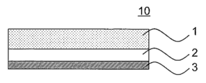
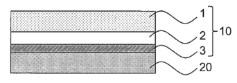
- the figure which shows a surface protection film The figure which shows the surface protection film affixed on the transparent substrate of the display surface.
- the surface protection film of this invention includes a protective layer 1, a transparent base film 2, and an adhesive layer made of a thermosetting polyurethane which is a cured product of a polyether polyol, an aliphatic isocyanate, an alcohol curing agent, and a non-amine catalyst. 3 layers are laminated in this order.
- the surface protective film 10 of the present invention is bonded to the transparent substrate 20 located on the outermost surface of the display with the pressure-sensitive adhesive layer 3 to prevent the transparent substrate 20 from being scratched, cracked, soiled, and the like. Used for. 1 and 2, the thickness of each layer does not mean the actual thickness.
- the protective layer 1 of the present invention comprises a thermosetting polyurethane which is a cured product of a polyether polyol, an aliphatic isocyanate, an alcohol-based curing agent, and a non-amine catalyst.
- thermosetting polyurethane By using this specific thermosetting polyurethane, it is excellent in transparency and light transmission, and is excellent in scratch resistance, weather resistance, and self-repairability.
- thermosetting polyurethane which forms the protective layer 1 of the present invention uses polyether polyol as a polyol component.
- the thermosetting polyurethane obtained from the polyether polyol is excellent in hydrolysis resistance, flexibility and microbial degradation resistance, and has a small permanent set.
- the polyether polyol include polyethylene glycol, polypropylene glycol, polypropylene triol, polytetramethylene glycol, polypropylene tetraol, polytetramethylene triol, polyalkylene glycols such as copolymers thereof, side chains, and branched structures. Derivatives, modified products, etc., in which either or both are introduced. These can be used alone or in combination of two or more.
- polytetramethylene glycol is preferable from the viewpoint of mechanical properties.
- the number average molecular weight of the polyether polyol is preferably 200 or more and 10,000 or less, more preferably 500 or more and 5000 or less, and further preferably 800 or more and 3000 or less. If the number average molecular weight is less than 200, the reaction is too fast and the handleability is poor, and the molded product may lose flexibility and become brittle. On the other hand, if the number average molecular weight is greater than 10,000, the viscosity becomes too high and the handleability is poor, and the molded product may crystallize and become cloudy.
- the number average molecular weight means a molecular weight calculated from a hydroxyl value of a polyol measured according to JIS-K1557. However, even if outside the above numerical range, this is not excluded unless it deviates from the gist of the present invention.
- thermosetting polyurethane forming the protective layer 1 of the present invention uses an aliphatic isocyanate having no aromatic ring and having two or more isocyanate groups in the molecule as the isocyanate component.
- the thermosetting polyurethane obtained from the aliphatic isocyanate is unlikely to yellow, and can prevent the thermosetting polyurethane from being discolored by light or heat from a light source, sunlight, or the like, thereby reducing transparency.
- aliphatic isocyanate examples include hexamethylene diisocyanate, hydrogenated tolylene diisocyanate, hydrogenated diphenylmethane diisocyanate, isophorone diisocyanate, lysine diisocyanate, isopropylidenebis (4-cyclohexylisocyanate), norbornane diisocyanate, modified products and multimers thereof, and the like. Is mentioned. These can be used alone or in combination of two or more. Among these, hydrogenated diphenylmethane diisocyanate is preferable from the viewpoint of mechanical properties.
- thermosetting polyurethane forming the protective layer 1 of the present invention uses an alcohol-based curing agent as the curing agent.
- the alcohol-based curing agent has less adverse effects on the human body and the environment than the amine-based curing agent. Any alcohol-based curing agent can be used without particular limitation as long as it has two or more hydroxy groups in the molecule.
- the dihydric alcohol is 50 parts by weight or more and 100 parts by weight or less with respect to the total amount of the alcohol-based curing agent. It is preferably used in the range of 0 part by weight or more, and more preferably in the range of 60 parts by weight or more and 80 parts by weight or less of dihydric alcohol and 40 parts by weight or less of trihydric alcohol.
- the dihydric alcohol 1,4-butanediol, and as the trihydric alcohol, trimethylolpropane is preferable from the viewpoints of handling properties and mechanical properties.
- thermosetting polyurethane forming the protective layer 1 of the present invention is thermoset in the presence of a non-amine catalyst.
- the thermosetting polyurethane of the present invention is excellent in non-coloring property, transparency and weather resistance by using a non-amine catalyst.
- thermosetting polyurethane thermally cured with an amine-based catalyst emits yellow light, and the appearance is colored over time.
- Non-amine catalysts include, for example, organic tin compounds such as di-n-butyltin dilaurate, dimethyltin dilaurate, dibutyltin oxide, and octane tin, organic titanium compounds, organic zirconium compounds, carboxylic acid tin salts, and carboxylic acids. Bismuth salt etc. are mentioned. Among these, an organic tin compound is preferable because the reaction rate can be easily adjusted.
- Non-amine-based catalysts include the a. To c. It is preferable to add so that it may become 0.0005 weight% or more and 3.0 weight% or less with respect to the total amount.
- the reaction rate may not be sufficiently high, and a molded product may not be obtained efficiently. If it is larger than 3.0% by weight, the reaction rate becomes too fast to obtain a molded product having a uniform thickness, the heat resistance and weather resistance of the molded product are lowered, the light transmittance is lowered, and the molded product is reduced. Problems such as coloring of the body may occur. However, even if outside the above numerical range, this is not excluded unless it deviates from the gist of the present invention.
- thermosetting polyurethane forming the protective layer 1 is a colorant, a light stabilizer, a heat stabilizer, an antioxidant, an antifungal agent, a flame retardant, and a slip agent as necessary, as long as the required properties are not impaired.
- Various additives such as can be contained.
- the protective layer 1 is a molded body made of a thermosetting polyurethane obtained by curing a polyether polyol, an aliphatic isocyanate, and an alcohol curing agent with a non-amine catalyst.
- the molding method includes a one-shot method and a prepolymer. Either the method or the pseudo prepolymer method may be used.
- a polyether polyol, an aliphatic isocyanate, an alcohol-based curing agent, an optional additive, and a non-amine catalyst may be added all at once and cured to produce a thermosetting polyurethane molded body.
- a prepolymer method a prepolymer having an isocyanate group at a terminal is prepared in advance by reacting a polyether polyol with a stoichiometric excess of an aliphatic isocyanate, and a predetermined amount of an alcohol-based curing agent, What is necessary is just to produce the molded object of a thermosetting polyurethane by mixing arbitrary additives and a non-amine type catalyst, and hardening a prepolymer.
- thermosetting polyurethane molded object by mixing and hardening the mixture of an ether polyol, alcohol type hardening
- ⁇ ratio is preferably 0.8 or more and 1.2 or less. If it is less than 0.8, the mechanical properties become unstable, and if it is more than 1.2, the surface tackiness increases and good writing quality is impaired.
- a thermosetting polyurethane does not contain an acrylic skeleton (an acrylic skeleton or a methacryl skeleton).
- thermosetting polyurethane forming the protective layer 1 of the present invention does not contain acrylic-modified polyurethane.
- Thermosetting polyurethane having an acrylic skeleton may be used to introduce an acrylic skeleton or an acrylic skeleton, as the flexibility of the polyurethane may be impaired and the mechanical strength such as abrasion resistance and tear strength may decrease.
- the emitted light may be colored by the catalyst residue.
- the thickness of the protective layer 1 is preferably 100 ⁇ m or more and 300 ⁇ m or less.
- the protective layer 1 has a thickness of 100 ⁇ m or more and 300 ⁇ m or less, the writing quality and slipperiness of the touch pen are very good, the writing feeling is equivalent to that of paper, and it can be operated without feeling uncomfortable.
- the thickness of the protective layer 1 is less than 100 ⁇ m, the writing quality and self-healing properties are lowered, and when the thickness of the protective layer 1 is larger than 300 ⁇ m, the light transmittance, transparency, writing quality, slipperiness and self-healing properties are lowered. In addition, it becomes difficult to mold with a uniform thickness.
- the thickness of the protective layer 1 is more preferably 130 ⁇ m or more and 270 ⁇ m or less, further preferably 150 ⁇ m or more and 250 ⁇ m or less, and most preferably 180 ⁇ m or more and 220 ⁇ m or less.
- the haze value of the surface protective film is 0.1% to 40%, and the total light transmittance is 90% or more. If the haze value is greater than 40% or the total light transmittance is less than 90%, the visibility of the display is lowered.
- the surface protection film 10 has excellent transparency and a clear appearance.
- the antiglare property can be imparted to the surface protective film 10. Further, the surface protective film 10 having the antiglare property is less prone to scratches on the surface of the protective layer 1.
- the concavo-convex shape on the outermost surface of the protective layer 1 is not particularly limited as long as it has the above-described haze value and total light transmittance, and may be appropriately adjusted according to the refractive index, light absorption, etc. of the material used.
- the average length (RSm) of the roughness curve element is about 10 ⁇ m or more and 80 ⁇ m or less.
- the arithmetic average roughness Ra is about 0.01 ⁇ m or more and 0.3 ⁇ m or less, and the maximum height Rz is about 0.1 ⁇ m or more and 2.0 ⁇ m or less.
- the transparent substrate film 2 holds the protective layer 1.
- the material constituting the transparent base film 2 can be used without particular limitation as long as it is excellent in transparency, flexibility, and mechanical strength. Polyethylene terephthalate (PET), cyclic olefin resin (COP) Etc. can be used suitably.
- the thickness of the transparent substrate film 2 is preferably 50 ⁇ m or more and 300 ⁇ m or less.
- the protective layer 1 of the surface protective film 10 of the present invention is made of thermosetting polyurethane. Since the thermal expansion coefficient of the thermosetting polyurethane forming the protective layer 1 is usually larger than the thermal expansion coefficient of the material constituting the transparent base film 2, if the thickness of the transparent base film 2 is less than 50 ⁇ m, the temperature is low.
- the surface protective film 10 may be peeled off from the transparent substrate 20.
- the thickness of the transparent base film 2 is larger than 300 ⁇ m, the surface protection film 10 is bulky and the cost increases. Moreover, the operativity at the time of bonding on the touch-panel-type display surface falls.
- the protective layer 1 is directly formed on the transparent substrate film 2 as will be described in detail in “Method for producing protective layer 1” below.
- the transparent substrate film 2 is preferably thicker. However, even if outside the above numerical range, this is not excluded unless it deviates from the gist of the present invention.
- the pressure-sensitive adhesive layer 3 is for bonding the surface protective film 10 of the present invention to the transparent substrate 20 on the outermost surface of the display.
- the kind of the pressure-sensitive adhesive is not particularly limited, and acrylic resin, epoxy resin, urethane resin, and silicon resin can be used.
- the acrylic resin can be attached even to a surface substrate that has been subjected to a surface treatment such as an antifouling treatment or a low reflection treatment.
- the silicon-based resin is excellent in wettability, is less likely to generate bubbles when attached to a transparent substrate, and has good removability and hardly causes adhesive residue when peeled.
- the thickness of the pressure-sensitive adhesive layer 3 is usually in the range of 5 ⁇ m or more and 60 ⁇ m or less, but can be appropriately adjusted according to the required specifications.
- the surface protective film 10 of the present invention In order to protect the surface protective film 10 of the present invention from production until it is applied to the transparent substrate 20 and used, the surface protective film 10 is separated from the protective layer 1 side, the pressure-sensitive adhesive layer 3 side, and the respective surfaces.
- the mold film 4 and the release film 5 can be attached to form the surface protective film laminate 30.
- FIG. 3 shows the surface protective film laminate 30. In FIG. 3, the thickness of each layer does not mean the actual thickness.
- the release film 4 is to prevent the protective layer 1 from becoming dirty, adhered to dust, and the like, and it is preferable to use a film having a release treatment applied to the surface to be bonded to the protective layer 1.
- the release film 4 that has been subjected to the release treatment is peeled off from the protective layer 1, the release agent is transferred from the release film 4 to the surface of the protective layer 1, and the slipperiness to the surface of the protective layer 1 immediately after the release film is peeled off.
- the touch operation can be performed without a sense of incongruity.
- the protective layer 1 can be directly formed on the release film 4.
- the release film 4 is 50 micrometers or more and 300 micrometers or less, and the thicker one is more preferable.
- the release film 5 protects the pressure-sensitive adhesive layer 3 to prevent dirt, dust adhesion, lowering of adhesive strength, etc., and a release-treated film on the surface to be bonded to the pressure-sensitive adhesive layer 3 is used. It can be suitably used.
- the protective layer 1 separates a material composition containing at least a polyether polyol, an aliphatic isocyanate (or a urethane prepolymer comprising these), an alcohol-based curing agent, an optional additive, and a non-amine catalyst.
- the material composition is poured into a gap between the gap maintaining members fed out by a pair of rolls arranged in the same manner, introduced into a heating device in a state of being held between the gap maintaining members, and thermally cured.
- FIG. 4 the schematic diagram of the manufacturing method of the protective layer 1 is shown.
- the manufacturing method of the protective layer 1 is demonstrated using FIG.
- a material composition 40a containing at least a polyether polyol, an aliphatic isocyanate (or a urethane prepolymer comprising these), an alcohol-based curing agent, an optional additive, and a non-amine catalyst is passed through a casting machine 41. Then, it flows into the gap between the first and second gap maintaining members 42a and 42b sent out by the pair of transport rollers 43a and 43b that are spaced apart. The first and second gap maintaining members 42a and 42b are guided into the heating device 46 while holding the material composition 40a therebetween.
- the material composition 40a is thermoset while being held between the first and second gap maintaining members 42a and 42b, and becomes a thermosetting polyurethane sheet 40.
- 44 is a conveying roller for feeding out the first and second gap maintaining members 42a and 42b
- 45 is an auxiliary roller
- 47 is a first and second gap holding the material composition 40a. It is a conveyor belt for conveying the maintenance members 42a and 42b in the heating device 46.
- the gap can be maintained at a constant size.
- the material composition 40a is sandwiched between the first and second gap maintaining members 42a and 42b and is cured in a state of maintaining a constant thickness, the thermosetting polyurethane sheet-like material 40 having excellent thickness accuracy and Become.
- this manufacturing method it is possible to continuously form a sheet-like material 40 having a thickness of 30 ⁇ m or more, which is difficult to apply, and having practical optical characteristics as a surface protective film for a display.
- the position of the head portion 41a of the casting machine 41 is located on the side of one of the heating rolls from the central portion of the transport rolls 43a and 43b (the central portion of the gap formed by the first and second gap maintaining members 42a and 42b).
- the uneven distribution distance is preferably equal to or less than the radius of the transport roll. That is, it is preferable that the position immediately below the head portion 41a of the casting machine 41 is located between the central portion of the pair of transport rolls 43a and 43b and the central axis of one of the transport rolls.
- tip part of the head part 41a and the surface of a conveyance roll is 5 cm or less.
- the head portion 41a By disposing the head portion 41a in this way, the thickness accuracy of the thermosetting polyurethane sheet-like material 40 is further improved, and the head portion 41a is poured into the gap between the first and second gap maintaining members 42a and 42b. Bubbles are not easily mixed into the uncured material composition 40a, and the mixed bubbles are easily removed.
- the transport rolls 43a and 43b may have only a transport function, but are preferably heating rolls.
- the transport roll is a heating roll
- the material composition 40a can be cured immediately after being held in the gap between the first and second gap maintaining members 42a and 42b, and the resin composition 40a is heated by the heating device 46.
- the thickness can be more uniformly maintained before being introduced into the sheet, and the thermosetting polyurethane sheet-like product 40 having more excellent thickness accuracy can be formed. It is preferable to set the conveyance surface temperature at the time of heating a conveyance roll to 10 degreeC or more and 60 degrees C or less.
- the material composition 40 a may be cured on the transport roll, or bubbles may enter the sheet-like material 40.
- the heating device 46 is a heating furnace provided with a heater and may be anything that can raise the temperature in the furnace to the curing temperature of the material composition 40a.
- the heating conditions (curing conditions) in the heating device 46 are not particularly limited, and may be set as appropriate according to the composition of the material composition 40a, for example, 40 ° C. to 160 ° C., 1 minute to 180 minutes. It may be performed under the conditions of
- the heating device 46 From the heating device 46, a long laminate in which the first gap maintaining member 42a, the thermosetting polyurethane sheet 40, and the second gap maintaining member 42b are laminated in this order is carried out. And the sheet-like object 40 becomes the protective layer 1 of the surface protective film 10 of the present invention, and one of the first gap maintaining member 42a and the second gap maintaining member 42b is a transparent substrate of the surface protective film 10 of the present invention. Film 2 is obtained.
- the first gap maintaining member 42a is the transparent base film 2 will be described as an example.
- the 2nd clearance maintenance member 42b can be utilized as the release film 4 of the surface protection film laminated body 30 of this invention.
- the first gap maintaining member 42a to be the transparent base film 2 is not subjected to the release treatment, and the second gap maintaining member 42b to be the release film 4 is subjected to the release treatment. It is preferable to use a film. Further, by using a film having unevenness as the second gap maintaining member 42b and holding the material composition 40a on the surface having the unevenness, the unevenness is transferred to the outermost surface of the sheet-like material 40 to be the protective layer 1. Can do.
- the pressure-sensitive adhesive layer 3 is formed by coating on the surface of the first gap maintaining member 42a to be the transparent base film 2 of the long laminate carried out from the heating device, and the release film 5 is pasted on the pressure-sensitive adhesive layer 3 By combining them, the elongated surface protective film laminate 30 of the present invention is obtained.
- the peeling film 5 was bonded together through the adhesive layer 3 in the long transparent base film beforehand, and the laminated body which the transparent base film 2, the adhesive layer 3, and the peeling film 5 laminated
- this laminate can also be used as the first gap maintaining member 42a.
- the surface protective film laminated body 30 can be continuously manufactured by what is called a roll to roll.
- the manufactured surface protective film laminate 30 has the release film 4 and the release film 5 on both sides, can prevent the surface protective film 10 from being scratched, contaminated, and the like, and has excellent handleability. If it ships as the surface protection film laminated body 30, the elongate surface protective film laminated body 30 may be wound and shipped in a roll shape, and may be shipped after cut
- a surface protective film laminate 1 having a protective layer thickness of 100 ⁇ m was obtained by the above-described molding method.
- Example 2 In the same manner as in Example 1, a surface protective film laminate 2 having a protective layer thickness of 150 ⁇ m was obtained.
- Example 3 In the same manner as in Example 1, a surface protective film laminate 3 having a protective layer thickness of 200 ⁇ m was obtained.
- Example 4 In the same manner as in Example 1, a surface protective film laminate 4 having a protective layer thickness of 250 ⁇ m was obtained.
- Example 5" The thickness of the protective layer is 200 ⁇ m as in Example 1 except that the release film 4 is silicon-treated thickness 100 ⁇ m, Ra 0.186 ⁇ m, Rz 1.541 ⁇ m, RSm 35.61 ⁇ m. A surface protective film laminate 5 having unevenness was obtained.
- Example 6 The thickness of the protective layer is 200 ⁇ m and the outermost surface is the same as in Example 5 except that the uneven transfer PET having a silicon treatment thickness of 125 ⁇ m, Ra 0.081 ⁇ m, Rz 0.586 ⁇ m, and RSm 20.336 ⁇ m is used as the release film 4. A surface protective film laminate 6 having unevenness was obtained.
- “Comparative Example 2” The protective layer has a thickness of 200 ⁇ m and the outermost surface in the same manner as in Example 5 except that as the release film 4 concavo-convex transfer PET having a thickness of 100 ⁇ m, Ra 0.475 ⁇ m, Rz 2.48 ⁇ m, RSm 34.687 ⁇ m was used. A surface protective film laminate 8 having irregularities was obtained.
- “Load-displacement measurement” In order to determine the lower limit of the thickness of the protective layer, after peeling off the release film and the release film from the surface protective film laminates 1 and 3 obtained in Examples 1 and 3, the thickness was 100 ⁇ m and 200 ⁇ m, respectively. A certain protective layer was affixed to a measurement stand through an adhesive layer, and the amount of displacement when a load was applied to one point was measured.
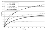
- FIG. 5 shows a graph of load-displacement measurement.
- a maximum displacement of about 47 ⁇ m was found on one sheet of paper, a maximum of about 105 ⁇ m was submerged on two sheets of paper, and a maximum displacement of about 179 ⁇ m was confirmed on five sheets of paper. Therefore, in order to obtain a feeling as if writing on paper, a subsidence displacement amount exceeding 47 ⁇ m is necessary. Particularly, in order to obtain a feeling as if writing is performed on two or more sheets of paper. It was confirmed that a subsidence displacement amount exceeding 105 ⁇ m was necessary. It was found that the protective layer having a thickness of 100 ⁇ m sinks up to about 93 ⁇ m.
- This amount of displacement is considered to be equivalent to 1.8 sheets of paper, which is well beyond the amount of displacement of one sheet of paper, and was confirmed to be close to that of two sheets of paper. It was also found that the protective layer having a thickness of 200 ⁇ m sinks up to about 174 ⁇ m. The protective layer having a thickness of 200 ⁇ m showed a sinking displacement amount equivalent to that of five sheets of paper, and a writing feeling equivalent to that of the stacked papers could be obtained. From the above results, in order to obtain a feeling of writing on two or more sheets of paper, it is necessary to have a film thickness that can sufficiently exceed the displacement of one sheet of paper. It can be determined that a thickness of 100 ⁇ m or more is appropriate.
- the recessed depth was measured using a contact-type surface roughness meter (manufactured by Mitutoyo Corporation, apparatus name: SV-3000) for the recessed portion. .
- the writing quality can be evaluated by the subduction depth after 1 minute, and the writing quality becomes better as the subduction depth increases.
- Self-healing properties can be evaluated by the depth of sinking after 15 minutes, and the smaller the value, the better the self-healing properties.
- Measurement conditions Measurement length: 2.85 mm, speed: 0.05 mm / s, pitch: 0.2 ⁇ m Evaluation conditions Standard: JIS2001, evaluation curve type: PJ01, reference length: 0.25 mm, number of sections: 5, ⁇ s: 0.0025 mm, filter type: Gaussian, evaluation length: 1.25 mm, run-up: 0.8 mm, Rear run: 0.8mm
- ⁇ Friction coefficient> A 15 cm ⁇ 5 cm sample was cut from the prepared surface protective film laminate, and the release film and the release film were peeled off. Then, variations in the static friction coefficient, dynamic friction coefficient, and dynamic friction coefficient on the protective layer side were measured under the following conditions.
- a 2 cm square sample is cut from the prepared surface protective film laminate, the release film and the release film are peeled off, and observed with a laser microscope (manufactured by Keyence Corporation, apparatus name: VK-9710) so that the protective layer side is on top I set it on the table.
- a laser microscope manufactured by Keyence Corporation, apparatus name: VK-9710
- measurement was performed with Z measurement pitch: 0.02 ⁇ m
- measurement mode surface shape
- measurement area surface
- measurement quality high speed.
- Laser brightness adjustment was set to automatic adjustment mode.
- the secondary curved surface correction (automatic) mode was selected as the inclination correction, and the image processing was performed.
- the surface protective film of the present invention obtained in Examples 1 to 4 had excellent performance as a surface protective film such as smoothness, light transmittance, transparency, and weather resistance. Moreover, the surface protective film of the present invention obtained in Examples 5 and 6 was an excellent surface protective film having antiglare property.
- the surface protective film 7 obtained in Comparative Example 1 was inferior in scratch resistance due to insufficient strength of the thermosetting polyurethane used.
- the surface protective film 8 obtained in Comparative Example 2 had a haze value of 60% or more, and had an antiglare property, but the visibility was lowered.
- Example 1 in which the protective layer thickness was 100 ⁇ m was higher than Example 2 in which the protective layer thickness was 150 ⁇ m.
- the depth of subduction after 15 minutes was great.
- the thicker the protective layer the larger the static friction coefficient, the dynamic friction coefficient, and the variation of the dynamic friction coefficient.
- the greater the sinking depth after 1 minute the better the writing quality.
- the greater the sinking depth after 15 minutes the lower the self-repairing property.
- the surface protective film of the present invention obtained in Examples 1 to 4 was excellent in operability and use feeling when using a touch pen, but in particular, Example 3 having a protective layer thickness of 200 ⁇ m was excellent. .
Landscapes
- Chemical & Material Sciences (AREA)
- Organic Chemistry (AREA)
- Health & Medical Sciences (AREA)
- Chemical Kinetics & Catalysis (AREA)
- Medicinal Chemistry (AREA)
- Polymers & Plastics (AREA)
- Materials Engineering (AREA)
- Engineering & Computer Science (AREA)
- Life Sciences & Earth Sciences (AREA)
- Wood Science & Technology (AREA)
- Inorganic Chemistry (AREA)
- Physics & Mathematics (AREA)
- Thermal Sciences (AREA)
- Laminated Bodies (AREA)
- Casting Or Compression Moulding Of Plastics Or The Like (AREA)
- Adhesive Tapes (AREA)
Abstract
本発明は、平滑性、光透過性、透明性、耐擦傷性、耐候性、自己修復性に優れた表面保護フィルムを提供することを課題とする。解決手段として、ポリエーテルポリオールと脂肪族イソシアネートとアルコール系硬化剤と非アミン系触媒の硬化物である熱硬化性ポリウレタンからなる保護層、透明基材フィルム、粘着剤層の三層がこの順に積層されている表面保護フィルムを提供する。
Description
本発明はディスプレイ表面の透明基板を保護するための表面保護フィルムに関する。
スマートフォン、タブレット型PC、音楽プレーヤー等の携帯型電子機器において、ディスプレイ表面の透明基板を保護するために、表面保護フィルムを貼り合わせる場合がある。表面保護フィルムには、光透過性、透明性、耐擦傷性、耐候性などが求められる。また、近年、携帯型電子機器は、静電容量式タッチパネルにより操作されることが一般的となり、指紋や皮脂がつきにくい防汚性、タッチペンの書き味、滑り性、タッチペンの先端で押し込まれたフィルムが経時で元に戻る自己修復性などが新たに求められている。
表面保護フィルムとして、例えば、特許文献1には、透明基材フィルムの一方の面に、ウレタン(メタ)アクリレートとフッ素含有化合物及び/またはシロキサン結合を有する化合物からなる軟質樹脂層を有する保護フィルムが提案されている。特許文献1には、軟質樹脂層の厚みは5~200μmが好ましいこと、軟質樹脂層は湿式成膜法で塗布して塗膜を形成し、塗膜を乾燥した後、紫外線照射を行って形成されることが記載されている。特許文献1の軟質樹脂層は、低表面張力成分であるフッ素含有化合物及び/またはシロキサン結合を有する化合物を含有するため、塗膜が乾燥するまでに低表面張力成分が分離して、濁りが生じやすく、均一な透明塗膜の形成が困難である。また、湿式成膜法では、30μm以上の厚さの塗膜を、表面保護フィルムに求められるレベルの光学特性を維持して形成することは非常に困難である。
特許文献2には、基材フィルムと自己修復性樹脂層を含む自己修復性積層体の発明が提案されている。特許文献2には、自己修復性樹脂層の厚みは10~60μmの範囲が好ましいこと、自己修復性樹脂層を形成する樹脂としては、ポリカプロラクトンを有するポリオールとポリイソシアネートとから得られる熱硬化性ポリウレタンが好ましいこと、基材フィルム上に自己修復性樹脂層用組成物を、連続的に塗工し、必要に応じて乾燥し、次いで加熱により硬化して自己修復性樹脂層を形成することが記載されている。しかしながら、ポリカプロラクトン系ポリオールからなるポリウレタンは、他のエステル系ポリオールと比較すると加水分解性に優れるが、エーテル系ポリオールと比較すると加水分解性に劣る。また、特許文献1と同じく、30μm以上の厚さの塗膜を、表面保護フィルムに求められるレベルの光学特性を維持して形成することは非常に困難である。
特許文献2には、基材フィルムと自己修復性樹脂層を含む自己修復性積層体の発明が提案されている。特許文献2には、自己修復性樹脂層の厚みは10~60μmの範囲が好ましいこと、自己修復性樹脂層を形成する樹脂としては、ポリカプロラクトンを有するポリオールとポリイソシアネートとから得られる熱硬化性ポリウレタンが好ましいこと、基材フィルム上に自己修復性樹脂層用組成物を、連続的に塗工し、必要に応じて乾燥し、次いで加熱により硬化して自己修復性樹脂層を形成することが記載されている。しかしながら、ポリカプロラクトン系ポリオールからなるポリウレタンは、他のエステル系ポリオールと比較すると加水分解性に優れるが、エーテル系ポリオールと比較すると加水分解性に劣る。また、特許文献1と同じく、30μm以上の厚さの塗膜を、表面保護フィルムに求められるレベルの光学特性を維持して形成することは非常に困難である。
本発明は、平滑性、光透過性、透明性、耐擦傷性、耐候性、自己修復性に優れた表面保護フィルムを提供することを課題とする。
上記課題を解決するための、本発明の構成は以下のとおりである。
1.ポリエーテルポリオールと脂肪族イソシアネートとアルコール系硬化剤と非アミン系触媒の硬化物である熱硬化性ポリウレタンからなる保護層、透明基材フィルム、粘着剤層の三層がこの順に積層されていることを特徴とする表面保護フィルム。
2.前記保護層の厚さが100μm以上300μm以下であることを特徴とする1.に記載の表面保護フィルム。
3.前記アルコール系硬化剤が2価アルコール50重量部以上100重量部以下、3価アルコール50重量部以下0重量部以上の混合物であることを特徴とする1.または2.に記載の表面保護フィルム。
4.ヘイズ値が0.1%以上40%以下であることを特徴とする1.~3.のいずれかに記載の表面保護フィルム。
5.1.~4.のいずれかに記載の表面保護フィルムの前記保護層側表面に離型フィルム、前記粘着剤層側表面に剥離フィルムが積層されていることを特徴とする表面保護フィルム積層体。
6.ポリエーテルポリオールと脂肪族イソシアネートとアルコール系硬化剤とを非アミン系触媒で硬化させた熱硬化性ポリウレタンからなる保護層、透明基材フィルム、粘着剤層の三層がこの順に積層されていることを特徴とする表面保護フィルムの製造方法であって、
ポリエーテルポリオールと脂肪族イソシアネートとアルコール系硬化剤と非アミン系触媒とを含む材料組成物を、離間して配置された一対のロールにより送り出される第一および第二の間隙維持部材の間隙に流し込み、
前記材料組成物を、前記第一および第二の間隙維持部材の間に保持された状態で熱硬化して前記保護層とし、
前記第一および第二の間隙維持部材の一方を前記透明基材フィルムとすることを特徴とする表面保護フィルムの製造方法。
7.前記第一および第二の間隙維持部材の一方が離型処理が施されていないフィルム、他方が離型処理が施されているフィルムであることを特徴とする6.に記載の表面保護フィルムの製造方法。
8.前記第一および第二の間隙維持部材の他方が凹凸を有するフィルムであり、該凹凸を有する面で材料組成物を保持することを特徴とする6.または7.に記載の表面保護フィルムの製造方法。
1.ポリエーテルポリオールと脂肪族イソシアネートとアルコール系硬化剤と非アミン系触媒の硬化物である熱硬化性ポリウレタンからなる保護層、透明基材フィルム、粘着剤層の三層がこの順に積層されていることを特徴とする表面保護フィルム。
2.前記保護層の厚さが100μm以上300μm以下であることを特徴とする1.に記載の表面保護フィルム。
3.前記アルコール系硬化剤が2価アルコール50重量部以上100重量部以下、3価アルコール50重量部以下0重量部以上の混合物であることを特徴とする1.または2.に記載の表面保護フィルム。
4.ヘイズ値が0.1%以上40%以下であることを特徴とする1.~3.のいずれかに記載の表面保護フィルム。
5.1.~4.のいずれかに記載の表面保護フィルムの前記保護層側表面に離型フィルム、前記粘着剤層側表面に剥離フィルムが積層されていることを特徴とする表面保護フィルム積層体。
6.ポリエーテルポリオールと脂肪族イソシアネートとアルコール系硬化剤とを非アミン系触媒で硬化させた熱硬化性ポリウレタンからなる保護層、透明基材フィルム、粘着剤層の三層がこの順に積層されていることを特徴とする表面保護フィルムの製造方法であって、
ポリエーテルポリオールと脂肪族イソシアネートとアルコール系硬化剤と非アミン系触媒とを含む材料組成物を、離間して配置された一対のロールにより送り出される第一および第二の間隙維持部材の間隙に流し込み、
前記材料組成物を、前記第一および第二の間隙維持部材の間に保持された状態で熱硬化して前記保護層とし、
前記第一および第二の間隙維持部材の一方を前記透明基材フィルムとすることを特徴とする表面保護フィルムの製造方法。
7.前記第一および第二の間隙維持部材の一方が離型処理が施されていないフィルム、他方が離型処理が施されているフィルムであることを特徴とする6.に記載の表面保護フィルムの製造方法。
8.前記第一および第二の間隙維持部材の他方が凹凸を有するフィルムであり、該凹凸を有する面で材料組成物を保持することを特徴とする6.または7.に記載の表面保護フィルムの製造方法。
本発明の表面保護フィルムは、特定のポリウレタンからなる保護層を用いることにより、光透過性、透明性、耐擦傷性、耐候性、自己修復性に優れている。また、保護層の最表面に凹凸を形成することにより、防眩性を付与することもできる。2価アルコール50重量部以上100重量部以下、3価アルコール50重量部以下0重量部以上をアルコール系硬化剤として用いることにより、機械的強度をさらに高めることができる。
本発明の表面保護フィルムは、保護層が100μm以上300μm以下の厚みを有するにも関わらず、表面保護フィルムとして使用可能な光学特性を有し、100μm以上300μm以下の厚みを有することにより、タッチペンの書き味、滑り性が非常に良好であり、紙と同等の筆記感を有する。
本発明の表面保護フィルムに、離型フィルムと剥離フィルムとを積層した表面保護フィルム積層体は、保護層と粘着剤層とが保護されており、取り扱い性に優れている。
本発明の製造方法により、表面保護フィルムを連続的に製造することができる。さらに、湿式塗布法では製造が困難な100μm以上300μm以下の厚みを有する保護層を、光学特性を低下させることなく製造することができる。また、転写法により、保護層の表面に凹凸を容易に形成することができる。
本発明の表面保護フィルムは、保護層が100μm以上300μm以下の厚みを有するにも関わらず、表面保護フィルムとして使用可能な光学特性を有し、100μm以上300μm以下の厚みを有することにより、タッチペンの書き味、滑り性が非常に良好であり、紙と同等の筆記感を有する。
本発明の表面保護フィルムに、離型フィルムと剥離フィルムとを積層した表面保護フィルム積層体は、保護層と粘着剤層とが保護されており、取り扱い性に優れている。
本発明の製造方法により、表面保護フィルムを連続的に製造することができる。さらに、湿式塗布法では製造が困難な100μm以上300μm以下の厚みを有する保護層を、光学特性を低下させることなく製造することができる。また、転写法により、保護層の表面に凹凸を容易に形成することができる。
1 保護層
2 透明基材フィルム
3 粘着剤層
4 離型フィルム
5 剥離フィルム
10 表面保護フィルム
20 透明基板
30 表面保護フィルム積層体
40 シート状物
40a 材料組成物
41 注型機
41a ヘッド部
42a 第一の間隙維持部材
42b 第二の間隙維持部材
43a 搬送ロール
43b 搬送ロール
44 搬送ローラ
45 補助ローラ
46 加熱装置
47 コンベアベルト
2 透明基材フィルム
3 粘着剤層
4 離型フィルム
5 剥離フィルム
10 表面保護フィルム
20 透明基板
30 表面保護フィルム積層体
40 シート状物
40a 材料組成物
41 注型機
41a ヘッド部
42a 第一の間隙維持部材
42b 第二の間隙維持部材
43a 搬送ロール
43b 搬送ロール
44 搬送ローラ
45 補助ローラ
46 加熱装置
47 コンベアベルト
図1に、本発明の表面保護フィルムを示す。
本発明の表面保護フィルム10は、ポリエーテルポリオールと脂肪族イソシアネートとアルコール系硬化剤と非アミン系触媒の硬化物である熱硬化性ポリウレタンからなる保護層1、透明基材フィルム2、粘着剤層3の三層がこの順に積層されていることを特徴とする。
図2に示すように、本発明の表面保護フィルム10は、ディスプレイ最表面に位置する透明基板20上に粘着剤層3で貼り合わせ、透明基板20の傷付き、ひび割れ、汚れ等を防止するために用いられる。なお、図1、2において、各層の厚さは実際の厚さを意味するものではない。
本発明の表面保護フィルム10は、ポリエーテルポリオールと脂肪族イソシアネートとアルコール系硬化剤と非アミン系触媒の硬化物である熱硬化性ポリウレタンからなる保護層1、透明基材フィルム2、粘着剤層3の三層がこの順に積層されていることを特徴とする。
図2に示すように、本発明の表面保護フィルム10は、ディスプレイ最表面に位置する透明基板20上に粘着剤層3で貼り合わせ、透明基板20の傷付き、ひび割れ、汚れ等を防止するために用いられる。なお、図1、2において、各層の厚さは実際の厚さを意味するものではない。
「保護層1」
本発明の保護層1は、ポリエーテルポリオールと脂肪族イソシアネートとアルコール系硬化剤と非アミン系触媒の硬化物である熱硬化性ポリウレタンからなる。この特定の熱硬化性ポリウレタンを使用することにより、透明性、光透過性に優れ、かつ耐擦傷性、耐候性、自己修復性に優れる。
本発明の保護層1は、ポリエーテルポリオールと脂肪族イソシアネートとアルコール系硬化剤と非アミン系触媒の硬化物である熱硬化性ポリウレタンからなる。この特定の熱硬化性ポリウレタンを使用することにより、透明性、光透過性に優れ、かつ耐擦傷性、耐候性、自己修復性に優れる。
a.ポリエーテルポリオール
本発明の保護層1を形成する熱硬化性ポリウレタンは、ポリオール成分としてポリエーテルポリオールを用いる。ポリエーテルポリオールから得られる熱硬化性ポリウレタンは、耐加水分解性、柔軟性、耐微生物分解性に優れるとともに、永久歪みが小さい。
ポリエーテルポリオールとしては、例えば、ポリエチレングリコール、ポリプロピレングリコール、ポリプロピレントリオール、ポリテトラメチレングリコール、ポリプロピレンテトラオール、ポリテトラメチレントリオール、これらの共重合体等のポリアルキレングリコール、これらに側鎖、分岐構造のいずれか、または両方を導入した誘導体、変性体等が挙げられる。これらは単独、または2種以上を併用して用いることができる。これらの中で、ポリテトラメチレングリコールが、力学物性の観点から好ましい。
ポリエーテルポリオールの数平均分子量は、200以上10000以下であることが好ましく、500以上5000以下であることがより好ましく、800以上3000以下であることがさらに好ましい。数平均分子量が200未満では、反応が速すぎて取り扱い性が悪く、また、成形物が柔軟性を失うとともに脆くなる場合がある。一方、数平均分子量が10000より大きいと、粘度が高くなりすぎて取り扱い性に劣り、また、成形物が結晶化して白濁する場合がある。なお、本発明において、数平均分子量は、JIS-K1557に準じて測定したポリオールの水酸基価より算出した分子量を意味する。但し、上記の数値範囲外であっても、本発明の主旨を逸脱しなければ、これを除外するものではない。
本発明の保護層1を形成する熱硬化性ポリウレタンは、ポリオール成分としてポリエーテルポリオールを用いる。ポリエーテルポリオールから得られる熱硬化性ポリウレタンは、耐加水分解性、柔軟性、耐微生物分解性に優れるとともに、永久歪みが小さい。
ポリエーテルポリオールとしては、例えば、ポリエチレングリコール、ポリプロピレングリコール、ポリプロピレントリオール、ポリテトラメチレングリコール、ポリプロピレンテトラオール、ポリテトラメチレントリオール、これらの共重合体等のポリアルキレングリコール、これらに側鎖、分岐構造のいずれか、または両方を導入した誘導体、変性体等が挙げられる。これらは単独、または2種以上を併用して用いることができる。これらの中で、ポリテトラメチレングリコールが、力学物性の観点から好ましい。
ポリエーテルポリオールの数平均分子量は、200以上10000以下であることが好ましく、500以上5000以下であることがより好ましく、800以上3000以下であることがさらに好ましい。数平均分子量が200未満では、反応が速すぎて取り扱い性が悪く、また、成形物が柔軟性を失うとともに脆くなる場合がある。一方、数平均分子量が10000より大きいと、粘度が高くなりすぎて取り扱い性に劣り、また、成形物が結晶化して白濁する場合がある。なお、本発明において、数平均分子量は、JIS-K1557に準じて測定したポリオールの水酸基価より算出した分子量を意味する。但し、上記の数値範囲外であっても、本発明の主旨を逸脱しなければ、これを除外するものではない。
b.脂肪族イソシアネート
本発明の保護層1を形成する熱硬化性ポリウレタンは、イソシアネート成分として、芳香環を有さず、分子中にイソシアネート基を2個以上有する脂肪族イソシアネートを用いる。脂肪族イソシアネートから得られる熱硬化性ポリウレタンは、黄変しにくく、光源、太陽光線等からの光や熱により、熱硬化性ポリウレタンが変色して透明性が低下することを防ぐことができる。
脂肪族イソシアネートとしては、例えば、ヘキサメチレンジイソシアネート、水素化トリレンジイソシアネート、水素化ジフェニルメタンジイソシアネート、イソホロンジイソシアネート、リジンジイソシアネート、イソプロピリデンビス(4-シクロヘキシルイソシアネート)、ノルボルナンジイソシアネート、これらの変性体や多量体等が挙げられる。これらは単独、または2種以上を併用して用いることができる。これらの中で、水素化ジフェニルメタンジイソシアネートが、力学物性の観点から好ましい。
本発明の保護層1を形成する熱硬化性ポリウレタンは、イソシアネート成分として、芳香環を有さず、分子中にイソシアネート基を2個以上有する脂肪族イソシアネートを用いる。脂肪族イソシアネートから得られる熱硬化性ポリウレタンは、黄変しにくく、光源、太陽光線等からの光や熱により、熱硬化性ポリウレタンが変色して透明性が低下することを防ぐことができる。
脂肪族イソシアネートとしては、例えば、ヘキサメチレンジイソシアネート、水素化トリレンジイソシアネート、水素化ジフェニルメタンジイソシアネート、イソホロンジイソシアネート、リジンジイソシアネート、イソプロピリデンビス(4-シクロヘキシルイソシアネート)、ノルボルナンジイソシアネート、これらの変性体や多量体等が挙げられる。これらは単独、または2種以上を併用して用いることができる。これらの中で、水素化ジフェニルメタンジイソシアネートが、力学物性の観点から好ましい。
c.アルコール系硬化剤
本発明の保護層1を形成する熱硬化性ポリウレタンは、硬化剤としては、アルコール系硬化剤を使用する。アルコール系硬化剤は、アミン系硬化剤と比較して人体、環境への悪影響が小さい。
アルコール系硬化剤としては、分子中に2つ以上のヒドロキシ基を有するものであれば、特に制限することなく使用することができる。例えば、エチレングリコール、1,3-プロパンジオール、2-メチル-1,3-プロパンジオール、1,3-ブタンジオール、1,4-ブタンジオール、1,5-ペンタンジオール、ネオペンチルグリコール(2,2-ジメチル-1,3-プロパンジオール)、1,6-ヘキサンジオール、ポリエチレングリコール、ポリプロピレングリコール、ポリブチレングリコール、シクロヘキサンジメタノール、水素添加ビスフェノールA等の2価アルコール、グリセリン、トリメチロールプロパン、ブタントリオール、ペンタントリオール、ヘキサントリオール、シクロペンタントリオール、シクロヘキサントリオール等の3価アルコール、ペンタエリスリトール、ジペンタエリスリトール、テトラメチロールプロパン等の3価以上のアルコールが挙げられる。これらの中で、2価アルコール単独、または、2価アルコールと3価アルコールとを併用することが好ましい。3価アルコールの量が多いと得られる熱硬化性ポリウレタンの強度が低下するため、アルコール系硬化剤の全量に対して、2価アルコール50重量部以上100重量部以下、3価アルコール50重量部以下0重量部以上の範囲で用いることが好ましく、2価アルコール60重量部以上80重量部以下、3価アルコール40重量部以下20重量部以上の範囲で用いることがさらに好ましい。2価アルコールとしては、1,4-ブタンジオール、3価アルコールとしてはトリメチロールプロパンが、取り扱い性、力学物性の観点から好ましい。
本発明の保護層1を形成する熱硬化性ポリウレタンは、硬化剤としては、アルコール系硬化剤を使用する。アルコール系硬化剤は、アミン系硬化剤と比較して人体、環境への悪影響が小さい。
アルコール系硬化剤としては、分子中に2つ以上のヒドロキシ基を有するものであれば、特に制限することなく使用することができる。例えば、エチレングリコール、1,3-プロパンジオール、2-メチル-1,3-プロパンジオール、1,3-ブタンジオール、1,4-ブタンジオール、1,5-ペンタンジオール、ネオペンチルグリコール(2,2-ジメチル-1,3-プロパンジオール)、1,6-ヘキサンジオール、ポリエチレングリコール、ポリプロピレングリコール、ポリブチレングリコール、シクロヘキサンジメタノール、水素添加ビスフェノールA等の2価アルコール、グリセリン、トリメチロールプロパン、ブタントリオール、ペンタントリオール、ヘキサントリオール、シクロペンタントリオール、シクロヘキサントリオール等の3価アルコール、ペンタエリスリトール、ジペンタエリスリトール、テトラメチロールプロパン等の3価以上のアルコールが挙げられる。これらの中で、2価アルコール単独、または、2価アルコールと3価アルコールとを併用することが好ましい。3価アルコールの量が多いと得られる熱硬化性ポリウレタンの強度が低下するため、アルコール系硬化剤の全量に対して、2価アルコール50重量部以上100重量部以下、3価アルコール50重量部以下0重量部以上の範囲で用いることが好ましく、2価アルコール60重量部以上80重量部以下、3価アルコール40重量部以下20重量部以上の範囲で用いることがさらに好ましい。2価アルコールとしては、1,4-ブタンジオール、3価アルコールとしてはトリメチロールプロパンが、取り扱い性、力学物性の観点から好ましい。
d.非アミン系触媒
本発明の保護層1を形成する熱硬化性ポリウレタンは、非アミン系触媒の存在下で熱硬化させる。本発明の熱硬化性ポリウレタンは、非アミン系触媒を使用することにより、非着色性、透明性、耐候性に優れている。それに対し、アミン系触媒で熱硬化させた熱硬化性ポリウレタンは、出射光が黄色くなり、また、経時で外観が着色してしまう。
非アミン系触媒としては、例えば、ジラウリル酸ジ-n-ブチル錫、ジラウリル酸ジメチル錫、ジブチル錫オキシド、オクタン錫等の有機錫化合物、有機チタン化合物、有機ジルコニウム化合物、カルボン酸錫塩、カルボン酸ビスマス塩等が挙げられる。これらの中で、有機錫化合物が、反応速度を調節しやすいため好ましい。
非アミン系触媒は、上記したa.~c.の総量に対して、0.0005重量%以上3.0重量%以下となるように添加することが好ましい。0.0005重量%未満では、反応速度が十分に速くならず、効率よく成形体を得ることができない場合がある。3.0重量%より大きいと、反応速度が速くなりすぎて、均一な厚みの成形体を得ることができなくなる、成形体の耐熱性や耐候性が低下する、光透過率が低下する、成形体が着色するなどの不具合を生じる場合がある。但し、上記の数値範囲外であっても、本発明の主旨を逸脱しなければ、これを除外するものではない。
本発明の保護層1を形成する熱硬化性ポリウレタンは、非アミン系触媒の存在下で熱硬化させる。本発明の熱硬化性ポリウレタンは、非アミン系触媒を使用することにより、非着色性、透明性、耐候性に優れている。それに対し、アミン系触媒で熱硬化させた熱硬化性ポリウレタンは、出射光が黄色くなり、また、経時で外観が着色してしまう。
非アミン系触媒としては、例えば、ジラウリル酸ジ-n-ブチル錫、ジラウリル酸ジメチル錫、ジブチル錫オキシド、オクタン錫等の有機錫化合物、有機チタン化合物、有機ジルコニウム化合物、カルボン酸錫塩、カルボン酸ビスマス塩等が挙げられる。これらの中で、有機錫化合物が、反応速度を調節しやすいため好ましい。
非アミン系触媒は、上記したa.~c.の総量に対して、0.0005重量%以上3.0重量%以下となるように添加することが好ましい。0.0005重量%未満では、反応速度が十分に速くならず、効率よく成形体を得ることができない場合がある。3.0重量%より大きいと、反応速度が速くなりすぎて、均一な厚みの成形体を得ることができなくなる、成形体の耐熱性や耐候性が低下する、光透過率が低下する、成形体が着色するなどの不具合を生じる場合がある。但し、上記の数値範囲外であっても、本発明の主旨を逸脱しなければ、これを除外するものではない。
保護層1を形成する熱硬化性ポリウレタンは、その要求特性を阻害しない範囲で、必要に応じて、着色剤、光安定剤、熱安定剤、酸化防止剤、防黴剤、難燃剤、滑り剤等の各種添加剤を含有することができる。
保護層1は、ポリエーテルポリオールと脂肪族イソシアネートとアルコール系硬化剤とを、非アミン系触媒で硬化させた熱硬化性ポリウレタンからなる成形体であり、その成形方法は、ワンショット法、プレポリマー法、擬プレポリマー法のいずれでもよい。
ワンショット法では、ポリエーテルポリオール、脂肪族イソシアネート、アルコール系硬化剤、任意の添加剤、非アミン系触媒を一括して投入し、硬化させることにより熱硬化性ポリウレタンの成形体を作製すればよい。
プレポリマー法では、ポリエーテルポリオールと化学量論的に過剰量の脂肪族イソシアネートとを反応させて末端にイソシアネート基を有するプレポリマーを予め調製しておき、ここに所定量のアルコール系硬化剤、任意の添加剤、非アミン系触媒を混合して、プレポリマーを硬化させることにより熱硬化性ポリウレタンの成形体を作製すればよい。
擬プレポリマー法では、ポリエーテルポリオールの一部を予めアルコール系硬化剤に混合しておき、残りのポリエーテルポリオールと脂肪族イソシアネートによりプレポリマーの調製を行い、ここに予め混合しておいたポリエーテルポリオールとアルコール系硬化剤、任意の添加剤、非アミン系触媒との混合物を混合して硬化させることにより熱硬化性ポリウレタンの成形体を作製すればよい。
プレポリマー法では、ポリエーテルポリオールと化学量論的に過剰量の脂肪族イソシアネートとを反応させて末端にイソシアネート基を有するプレポリマーを予め調製しておき、ここに所定量のアルコール系硬化剤、任意の添加剤、非アミン系触媒を混合して、プレポリマーを硬化させることにより熱硬化性ポリウレタンの成形体を作製すればよい。
擬プレポリマー法では、ポリエーテルポリオールの一部を予めアルコール系硬化剤に混合しておき、残りのポリエーテルポリオールと脂肪族イソシアネートによりプレポリマーの調製を行い、ここに予め混合しておいたポリエーテルポリオールとアルコール系硬化剤、任意の添加剤、非アミン系触媒との混合物を混合して硬化させることにより熱硬化性ポリウレタンの成形体を作製すればよい。
本発明のポリウレタン組成物では、アルコール系硬化剤に含まれる水酸基(-OH)のモル数と、脂肪族イソシアネートまたはプレポリマーのイソシアネート基(-NCO)のモル数との比(-OH/-NCO:以下、α比という。)が、0.8以上1.2以下であることが好ましい。0.8未満では、力学物性が不安定になり、1.2より大きいと、表面粘着性が増し、良好な書き味が損なわれる。
また、熱硬化性ポリウレタンは、アクリル骨格(アクリル骨格又はメタクリル骨格)を含有しないことが好ましい。すなわち、本発明の保護層1を形成する熱硬化性ポリウレタンは、アクリル変性ポリウレタンを含まないことが好ましい。アクリル骨格を有する熱硬化性ポリウレタンは、ポリウレタンの柔軟性が損なわれるとともに耐摩耗性や引裂強度などの力学的強度が低下することがあり、また、アクリル骨格又はアクリル骨格を導入するために使用した触媒の残渣により、出射光が着色することがある。
また、熱硬化性ポリウレタンは、アクリル骨格(アクリル骨格又はメタクリル骨格)を含有しないことが好ましい。すなわち、本発明の保護層1を形成する熱硬化性ポリウレタンは、アクリル変性ポリウレタンを含まないことが好ましい。アクリル骨格を有する熱硬化性ポリウレタンは、ポリウレタンの柔軟性が損なわれるとともに耐摩耗性や引裂強度などの力学的強度が低下することがあり、また、アクリル骨格又はアクリル骨格を導入するために使用した触媒の残渣により、出射光が着色することがある。
保護層1の厚みは、100μm以上300μm以下が好ましい。保護層1が100μm以上300μm以下の厚みを有することにより、タッチペンの書き味、滑り性が非常に良好で紙と同等の筆記感を有し、違和感を覚えることなく操作することができる。保護層1の厚みが100μm未満では、書き味、自己修復性が低下し、保護層1の厚みが300μmより厚いと、光透過性、透明性、書き味、滑り性、自己修復性が低下し、また、均一な厚さで成形することが困難となる。100μm以上300μm以下であれば、表面保護フィルムに求められる性能がバランスよく発揮され、また、製造も容易である。保護層1の厚みは、130μm以上270μm以下がより好ましく、150μm以上250μm以下がさらに好ましく、180μm以上220μm以下が最も好ましい。
表面保護フィルムのヘイズ値は、0.1%以上40%以下、全光線透過率は90%以上である。ヘイズ値が40%より大きい、または、全光線透過率が90%未満であると、ディスプレイの視認性が低下する。表面保護フィルム10のヘイズ値が0.1%以上3%未満であると、透明性に優れ、クリアな外観にすることができる。表面保護フィルム10のヘイズ値が3%以上40%以下であると、表面保護フィルム10に防眩性を付与することができる。また、防眩性を有する表面保護フィルム10は、保護層1表面に付いた傷が目立ちにくい。表面保護フィルムのヘイズ値を3%以上40%以下とするには、保護層1の最表面に凹凸を形成すればよい。保護層1最表面の凹凸形状は、上記したヘイズ値と全光線透過率を有するものであれば特に限定されず、使用する材料の屈折率や光吸収性等に応じて適宜調整すればよいが、通常、粗さ曲線要素の平均長さ(RSm)が10μm以上80μm以下程度である。また、算術平均粗さRaは、0.01μm以上0.3μm以下程度、最大高さRzは、0.1μm以上2.0μm以下程度である。
「透明基材フィルム2」
透明基材フィルム2は、保護層1を保持するものである。透明基材フィルム2を構成する材料は、透明性、可撓性、機械的強度に優れるものであれば特に制限することなく用いることができ、ポリエチレンテレフタレート(PET)、環状オレフィン系樹脂(COP)などを好適に用いることができる。
透明基材フィルム2の厚さは、50μm以上300μm以下であることが好ましい。本発明の表面保護フィルム10の保護層1は、熱硬化性ポリウレタンからなる。保護層1を形成する熱硬化性ポリウレタンの熱膨張係数は、通常、透明基材フィルム2を構成する材料の熱膨張係数よりも大きいため、透明基材フィルム2の厚さが50μm未満では、低温時に保護層1の収縮により、透明基材フィルム2端部に内側への応力が加わり、表面保護フィルム10が透明基板20から剥がれることがある。透明基材フィルム2の厚さが300μmより厚いと、表面保護フィルム10が嵩張り、コストが増加する。また、タッチパネル式のディスプレイ表面に貼り合わせた際の操作性が低下する。なお、下記「保護層1の製造方法」で詳述するが、保護層1は、透明基材フィルム2上に直接成形される。熱硬化性ポリウレタンを熱硬化させて保護層1とする際の加熱時の変形を防ぐために、透明基材フィルム2は厚いほうが好ましい。但し、上記の数値範囲外であっても、本発明の主旨を逸脱しなければ、これを除外するものではない。
透明基材フィルム2は、保護層1を保持するものである。透明基材フィルム2を構成する材料は、透明性、可撓性、機械的強度に優れるものであれば特に制限することなく用いることができ、ポリエチレンテレフタレート(PET)、環状オレフィン系樹脂(COP)などを好適に用いることができる。
透明基材フィルム2の厚さは、50μm以上300μm以下であることが好ましい。本発明の表面保護フィルム10の保護層1は、熱硬化性ポリウレタンからなる。保護層1を形成する熱硬化性ポリウレタンの熱膨張係数は、通常、透明基材フィルム2を構成する材料の熱膨張係数よりも大きいため、透明基材フィルム2の厚さが50μm未満では、低温時に保護層1の収縮により、透明基材フィルム2端部に内側への応力が加わり、表面保護フィルム10が透明基板20から剥がれることがある。透明基材フィルム2の厚さが300μmより厚いと、表面保護フィルム10が嵩張り、コストが増加する。また、タッチパネル式のディスプレイ表面に貼り合わせた際の操作性が低下する。なお、下記「保護層1の製造方法」で詳述するが、保護層1は、透明基材フィルム2上に直接成形される。熱硬化性ポリウレタンを熱硬化させて保護層1とする際の加熱時の変形を防ぐために、透明基材フィルム2は厚いほうが好ましい。但し、上記の数値範囲外であっても、本発明の主旨を逸脱しなければ、これを除外するものではない。
「粘着剤層3」
粘着剤層3は、ディスプレイ最表面の透明基板20に、本発明の表面保護フィルム10を貼り合わせるためのものである。粘着剤の種類は特に限定されず、アクリル系樹脂、エポキシ系樹脂、ウレタン系樹脂、シリコン系樹脂を用いることができる。これらの中で、アクリル系樹脂は、防汚処理、低反射処理等の表面処理がなされた表面基板であっても貼り付けることができる。また、シリコン系樹脂は、Wetting性に優れ、透明基板への貼り付け時に気泡が生じにくく、また、再剥離性がよく剥離時に糊残りしにくい。粘着剤層3の厚みは、通常5μm以上60μm以下の範囲内であるが、要求仕様に合わせて適宜調節することができる。
粘着剤層3は、ディスプレイ最表面の透明基板20に、本発明の表面保護フィルム10を貼り合わせるためのものである。粘着剤の種類は特に限定されず、アクリル系樹脂、エポキシ系樹脂、ウレタン系樹脂、シリコン系樹脂を用いることができる。これらの中で、アクリル系樹脂は、防汚処理、低反射処理等の表面処理がなされた表面基板であっても貼り付けることができる。また、シリコン系樹脂は、Wetting性に優れ、透明基板への貼り付け時に気泡が生じにくく、また、再剥離性がよく剥離時に糊残りしにくい。粘着剤層3の厚みは、通常5μm以上60μm以下の範囲内であるが、要求仕様に合わせて適宜調節することができる。
本発明の表面保護フィルム10を、生産から透明基板20へ貼付して使用されるまで保護するために、表面保護フィルム10の保護層1側、粘着剤層3側、それぞれの表面に、それぞれ離型フィルム4、剥離フィルム5を貼着し、表面保護フィルム積層体30とすることができる。図3に表面保護フィルム積層体30を示す。なお、図3において、各層の厚さは実際の厚さを意味するものではない。
離型フィルム4は、保護層1の汚れや埃付着等を防止するものであり、保護層1と貼り合わせる側の表面に離型処理が施されたフィルムを用いることが好ましい。離型処理が施された離型フィルム4を、保護層1から剥離すると、保護層1表面に離型フィルム4から離型剤が移行し、離型フィルム剥離直後の保護層1表面に滑り性を付与することができ、タッチ操作を違和感なく行うことができる。また、下記「保護層1の製造方法」で詳述するが、保護層1は、離型フィルム4上に直接成形することもできる。この際、熱硬化性ポリウレタンを熱硬化させて保護層1とする際の加熱時の変形を防ぐために、離型フィルム4は50μm以上300μm以下であることが好ましく、厚いほうがより好ましい。
剥離フィルム5は、粘着剤層3を保護して、汚れ、埃付着、粘着力の低下等を防ぐものであり、粘着剤層3と貼り合わせる側の表面に離型処理が施されたフィルムを好適に利用することができる。
離型フィルム4は、保護層1の汚れや埃付着等を防止するものであり、保護層1と貼り合わせる側の表面に離型処理が施されたフィルムを用いることが好ましい。離型処理が施された離型フィルム4を、保護層1から剥離すると、保護層1表面に離型フィルム4から離型剤が移行し、離型フィルム剥離直後の保護層1表面に滑り性を付与することができ、タッチ操作を違和感なく行うことができる。また、下記「保護層1の製造方法」で詳述するが、保護層1は、離型フィルム4上に直接成形することもできる。この際、熱硬化性ポリウレタンを熱硬化させて保護層1とする際の加熱時の変形を防ぐために、離型フィルム4は50μm以上300μm以下であることが好ましく、厚いほうがより好ましい。
剥離フィルム5は、粘着剤層3を保護して、汚れ、埃付着、粘着力の低下等を防ぐものであり、粘着剤層3と貼り合わせる側の表面に離型処理が施されたフィルムを好適に利用することができる。
「保護層1の製造方法」
保護層1は、少なくともポリエーテルポリオール、脂肪族イソシアネート(又は、これらからなるウレタンプレポリマー)、アルコール系硬化剤、任意の添加剤、並びに、非アミン系触媒を含有する材料組成物を、離間して配置された一対のロールにより送り出される間隙維持部材の間隙に流し込み、材料組成物が間隙維持部材の間に保持された状態で加熱装置に導入し、熱硬化することにより製造される。
保護層1は、少なくともポリエーテルポリオール、脂肪族イソシアネート(又は、これらからなるウレタンプレポリマー)、アルコール系硬化剤、任意の添加剤、並びに、非アミン系触媒を含有する材料組成物を、離間して配置された一対のロールにより送り出される間隙維持部材の間隙に流し込み、材料組成物が間隙維持部材の間に保持された状態で加熱装置に導入し、熱硬化することにより製造される。
図4に、保護層1の製造方法の模式図を示す。以下、図4を用いて保護層1の製造方法を説明する。
少なくともポリエーテルポリオール、脂肪族イソシアネート(又は、これらからなるウレタンプレポリマー)、アルコール系硬化剤、任意の添加剤、並びに、非アミン系触媒を含有する材料組成物40aを、注型機41を介して、離間して配置された一対の搬送ロール43a、43bにより送り出される第一、および第二の間隙維持部材42a、42bの間隙に流し込む。第一、および第二の間隙維持部材42a、42bは、その間に材料組成物40aを保持した状態で加熱装置46内に導かれる。材料組成物40aは、第一、および第二の間隙維持部材42a、42bの間に保持された状態で熱硬化して、熱硬化性ポリウレタンのシート状物40となる。
なお、図4において、44は第一、および第二の間隙維持部材42a、42bを送り出すための搬送ローラ、45は補助ローラ、47は材料組成物40aを保持した第一、および第二の間隙維持部材42a、42bを加熱装置46内で搬送するためのコンベアベルトである。
少なくともポリエーテルポリオール、脂肪族イソシアネート(又は、これらからなるウレタンプレポリマー)、アルコール系硬化剤、任意の添加剤、並びに、非アミン系触媒を含有する材料組成物40aを、注型機41を介して、離間して配置された一対の搬送ロール43a、43bにより送り出される第一、および第二の間隙維持部材42a、42bの間隙に流し込む。第一、および第二の間隙維持部材42a、42bは、その間に材料組成物40aを保持した状態で加熱装置46内に導かれる。材料組成物40aは、第一、および第二の間隙維持部材42a、42bの間に保持された状態で熱硬化して、熱硬化性ポリウレタンのシート状物40となる。
なお、図4において、44は第一、および第二の間隙維持部材42a、42bを送り出すための搬送ローラ、45は補助ローラ、47は材料組成物40aを保持した第一、および第二の間隙維持部材42a、42bを加熱装置46内で搬送するためのコンベアベルトである。
第一、および第二の間隙維持部材42a、42bは、その間に材料組成物40aを保持しながら同一の張力で引っ張られて搬送されるため、その間隙を一定の大きさに維持することができる。材料組成物40aは、第一、および第二の間隙維持部材42a、42bに挟まれ、一定の厚みを維持した状態で硬化するため、厚み精度に優れた熱硬化性ポリウレタンのシート状物40となる。この製造方法により、塗布では困難な30μm以上の厚みを有し、ディスプレイの表面保護フィルムとして実用的な光学特性を有するシート状物40を連続的に成形することができる。
注型機41のヘッド部41aの位置は、搬送ロール43a、43bの中央部(第一、および第二の間隙維持部材42a、42bがなす間隙の中央部)より、いずれか一方の加熱ロール側に偏在していることが好ましく、また、偏在距離が搬送ロールの半径以下であることが好ましい。すなわち、注型機41のヘッド部41aの直下は、一対の搬送ロール43a、43bの中央部から一方の搬送ロールの中心軸までの間に位置することが好ましい。また、ヘッド部41aの先端部と、搬送ロールの表面との最短距離は、5cm以下であることが好ましい。ヘッド部41aをこのように配設することにより、熱硬化性ポリウレタンのシート状物40の厚み精度がより向上するとともに、第一、および第二の間隙維持部材42a、42bの間隙に流し込まれた未硬化の材料組成物40aに気泡が混入しにくく、また、混入した気泡が抜けやすい。
搬送ロール43a、43bは、単に搬送機能のみを有するものでもよいが、加熱ロールであることが好ましい。搬送ロールが加熱ロールであると、材料組成物40aを、第一、および第二の間隙維持部材42a、42bの間隙に保持された直後から硬化させることができ、樹脂組成物40aが加熱装置46内に導入されるまでに厚さをより均一に維持することができ、より厚み精度に優れる熱硬化性ポリウレタンのシート状物40を成形することができる。搬送ロールを加熱する際の搬送面温度は、10℃以上60℃以下に設定することが好ましい。10℃未満では、材料組成物の粘度が高くなって気泡が抜けにくくなるとともに、硬化反応が遅くなってシート状物40の厚み精度が低下する。60℃を超えると、搬送ロール上で材料組成物40aが硬化したり、シート状物40に気泡が入ったりすることがある。
加熱装置46は、ヒータを備えた加熱炉であり、材料組成物40aの硬化温度まで炉内温度を上昇させることができるものであればよい。また、加熱装置46内での加熱条件(硬化条件)は特に限定されず、材料組成物40aの組成に応じて適宜設定すればよく、例えば、40℃以上160℃以下、1分以上180分以下の条件で行えばよい。
加熱装置46からは、第一の間隙維持部材42a、熱硬化性ポリウレタンのシート状物40、第二の間隙維持部材42bがこの順に積層した長尺状積層体が搬出される。そして、シート状物40が本発明の表面保護フィルム10の保護層1となり、第一の間隙維持部材42a、第二の間隙維持部材42bの一方が、本発明の表面保護フィルム10の透明基材フィルム2となる。以下、第一の間隙維持部材42aが、透明基材フィルム2となる場合を例として説明する。
第二の間隙維持部材42bは、本発明の表面保護フィルム積層体30の離型フィルム4として利用することができる。この際、透明基材フィルム2となる第一の間隙維持部材42aは離型処理が施されていないフィルム、離型フィルム4となる第二の間隙維持部材42bは離型処理が施されているフィルムを使用することが好ましい。
また、第二の間隙維持部材42bとして凹凸を有するフィルムを用い、凹凸を有する面で材料組成物40aを保持することにより、保護層1となるシート状物40の最表面に凹凸を転写することができる。
第二の間隙維持部材42bは、本発明の表面保護フィルム積層体30の離型フィルム4として利用することができる。この際、透明基材フィルム2となる第一の間隙維持部材42aは離型処理が施されていないフィルム、離型フィルム4となる第二の間隙維持部材42bは離型処理が施されているフィルムを使用することが好ましい。
また、第二の間隙維持部材42bとして凹凸を有するフィルムを用い、凹凸を有する面で材料組成物40aを保持することにより、保護層1となるシート状物40の最表面に凹凸を転写することができる。
加熱装置から搬出された長尺状積層体の透明基材フィルム2となる第一の間隙維持部材42a表面に、塗布により粘着剤層3を形成し、粘着剤層3上に剥離フィルム5を貼り合わせることにより、長尺状の本発明の表面保護フィルム積層体30が得られる。
なお、予め、長尺状の透明基材フィルムに粘着剤層3を介して剥離フィルム5を貼り合わせ、透明基材フィルム2、粘着剤層3、剥離フィルム5がこの順に積層した積層体を作製し、この積層体を第一間隙維持部材42aとして用いることもできる。
本製造方法により、表面保護フィルム積層体30をいわゆるロールtoロールで連続的に製造することができる。製造された表面保護フィルム積層体30は、両面にそれぞれ離型フィルム4と剥離フィルム5とを有し、表面保護フィルム10の傷付き、汚染等を防ぐことができ、取り扱い性に優れている。表面保護フィルム積層体30として出荷するのであれば、長尺状の表面保護フィルム積層体30をロール状に巻回して出荷してもよく、シート状に裁断してから出荷してもよい。また、第一の間隙維持部材42a、熱硬化性ポリウレタンのシート状物40、第二の間隙維持部材42bからなる長尺状積層体、またはこの積層体を裁断してから出荷し、ディスプレイ工場等で粘着剤層3を塗布により形成し、ディスプレイの透明基板に貼り合わせることもできる。
なお、予め、長尺状の透明基材フィルムに粘着剤層3を介して剥離フィルム5を貼り合わせ、透明基材フィルム2、粘着剤層3、剥離フィルム5がこの順に積層した積層体を作製し、この積層体を第一間隙維持部材42aとして用いることもできる。
本製造方法により、表面保護フィルム積層体30をいわゆるロールtoロールで連続的に製造することができる。製造された表面保護フィルム積層体30は、両面にそれぞれ離型フィルム4と剥離フィルム5とを有し、表面保護フィルム10の傷付き、汚染等を防ぐことができ、取り扱い性に優れている。表面保護フィルム積層体30として出荷するのであれば、長尺状の表面保護フィルム積層体30をロール状に巻回して出荷してもよく、シート状に裁断してから出荷してもよい。また、第一の間隙維持部材42a、熱硬化性ポリウレタンのシート状物40、第二の間隙維持部材42bからなる長尺状積層体、またはこの積層体を裁断してから出荷し、ディスプレイ工場等で粘着剤層3を塗布により形成し、ディスプレイの透明基板に貼り合わせることもできる。
以下、本発明について実施例を挙げてさらに詳しく説明するが、本発明はこれらの実施例のみに限定されるものではない。
「実施例1」
ポリテトラメチレングリコールをポリオール成分、水素化ジフェニルメタンジイソシアネートをイソシアネート成分とするプレポリマー(NCO%=10%)100gに対して、1,4-ブタンジオール/トリメチロールプロパン=60/40の重量比からなるアルコール系硬化剤を11.6g、非アミン系触媒として有機錫化合物を250ppm添加し、撹拌・混合を行った。
その後、離型フィルム4としてシリコン処理した厚み125μmのPETフィルム、透明基材フィルム2として厚み100μmのPETフィルム、粘着剤層3として厚み50μmのシリコン系粘着剤、剥離フィルム5としてシリコン処理した厚み75μmのPETフィルムを使用し、上記成形方法により、保護層の厚みが100μmの表面保護フィルム積層体1を得た。
「実施例1」
ポリテトラメチレングリコールをポリオール成分、水素化ジフェニルメタンジイソシアネートをイソシアネート成分とするプレポリマー(NCO%=10%)100gに対して、1,4-ブタンジオール/トリメチロールプロパン=60/40の重量比からなるアルコール系硬化剤を11.6g、非アミン系触媒として有機錫化合物を250ppm添加し、撹拌・混合を行った。
その後、離型フィルム4としてシリコン処理した厚み125μmのPETフィルム、透明基材フィルム2として厚み100μmのPETフィルム、粘着剤層3として厚み50μmのシリコン系粘着剤、剥離フィルム5としてシリコン処理した厚み75μmのPETフィルムを使用し、上記成形方法により、保護層の厚みが100μmの表面保護フィルム積層体1を得た。
「実施例2」
実施例1と同様にして、保護層の厚みが150μmの表面保護フィルム積層体2を得た。
「実施例3」
実施例1と同様にして、保護層の厚みが200μmの表面保護フィルム積層体3を得た。
「実施例4」
実施例1と同様にして、保護層の厚みが250μmの表面保護フィルム積層体4を得た。
実施例1と同様にして、保護層の厚みが150μmの表面保護フィルム積層体2を得た。
「実施例3」
実施例1と同様にして、保護層の厚みが200μmの表面保護フィルム積層体3を得た。
「実施例4」
実施例1と同様にして、保護層の厚みが250μmの表面保護フィルム積層体4を得た。
「実施例5」
離型フィルム4としてシリコン処理した厚み100μm、Ra0.186μm、Rz1.541μm、RSm35.61μmの凹凸転写PETを用いた以外は、実施例1と同様にして、保護層の厚みが200μmで、最表面に凹凸を有する表面保護フィルム積層体5を得た。
「実施例6」
離型フィルム4としてシリコン処理した厚み125μm、Ra0.081μm、Rz0.586μm、RSm20.336μmの凹凸転写PETを用いた以外は、実施例5と同様にして、保護層の厚みが200μmで、最表面に凹凸を有する表面保護フィルム積層体6を得た。
離型フィルム4としてシリコン処理した厚み100μm、Ra0.186μm、Rz1.541μm、RSm35.61μmの凹凸転写PETを用いた以外は、実施例1と同様にして、保護層の厚みが200μmで、最表面に凹凸を有する表面保護フィルム積層体5を得た。
「実施例6」
離型フィルム4としてシリコン処理した厚み125μm、Ra0.081μm、Rz0.586μm、RSm20.336μmの凹凸転写PETを用いた以外は、実施例5と同様にして、保護層の厚みが200μmで、最表面に凹凸を有する表面保護フィルム積層体6を得た。
「比較例1」
1,4-ブタンジオール/トリメチロールプロパン=40/60の重量比からなるアルコール系硬化剤を10.5g用いた以外は、実施例4と同様にして、保護層の厚みが250μmの表面保護フィルム積層体7を得た。
「比較例2」
離型フィルム4としてシリコン処理した厚み100μm、Ra0.475μm、Rz2.48μm、RSm34.687μmの凹凸転写PETを用いた以外は、実施例5と同様にして、保護層の厚みが200μmで、最表面に凹凸を有する表面保護フィルム積層体8を得た。
1,4-ブタンジオール/トリメチロールプロパン=40/60の重量比からなるアルコール系硬化剤を10.5g用いた以外は、実施例4と同様にして、保護層の厚みが250μmの表面保護フィルム積層体7を得た。
「比較例2」
離型フィルム4としてシリコン処理した厚み100μm、Ra0.475μm、Rz2.48μm、RSm34.687μmの凹凸転写PETを用いた以外は、実施例5と同様にして、保護層の厚みが200μmで、最表面に凹凸を有する表面保護フィルム積層体8を得た。
「荷重-変位測定」
保護層の厚さの下限を判断する為に、実施例1、3で得られた表面保護フィルム積層体1、3から、離型フィルム、剥離フィルムを剥がした後、それぞれ厚みが100μm、200μmである保護層を、粘着剤層を介して測定台に貼り付け、一点に荷重をかけた際の変位量を測定した。
また、一般的なコピー用紙(厚さ:0.09mm、坪量:67g/m2)を1枚、2枚重ね、5枚重ねにし、積層による紙の隙間を抑えるため、円環状の100gfの重りで紙を押さえつけ、円環中心の一点に荷重をかけた際の変位量を測定した。
測定は、角度85度の円錐に、0gfから、一般的な人の筆圧の上限である500gfまで荷重を加えて行った。
保護層の厚さの下限を判断する為に、実施例1、3で得られた表面保護フィルム積層体1、3から、離型フィルム、剥離フィルムを剥がした後、それぞれ厚みが100μm、200μmである保護層を、粘着剤層を介して測定台に貼り付け、一点に荷重をかけた際の変位量を測定した。
また、一般的なコピー用紙(厚さ:0.09mm、坪量:67g/m2)を1枚、2枚重ね、5枚重ねにし、積層による紙の隙間を抑えるため、円環状の100gfの重りで紙を押さえつけ、円環中心の一点に荷重をかけた際の変位量を測定した。
測定は、角度85度の円錐に、0gfから、一般的な人の筆圧の上限である500gfまで荷重を加えて行った。
図5に、荷重-変位測定のグラフを示す。
紙1枚では最大約47μm沈み込み、紙2枚では最大約105μm沈み込み、紙5枚では最大約179μm沈み込む変位量が確認された。よって、紙に筆記を行っているかのような感触を得るには47μmを越える沈み込み変位量が必要であり、特に2枚以上重ねた紙に筆記を行っているかのような感触を得るには105μmを越える沈み込み変位量が必要であることが確認できた。
厚さが100μmである保護層は、最大約93μm沈み込むことが分かった。この変位量は紙1.8枚相当と考えられ、紙1枚分の変位量を十分に超えており、紙2枚分に近いことが確かめられた。また、厚さが200μmである保護層は、最大約174μm沈み込むことが分かった。厚さ200μmである保護層は、紙5枚重ねと同等の沈み込み変位量を示し、重ね合わせた紙と同等の筆記感を得ることができた。
以上の結果より、特に2枚以上重ねた紙に筆記を行っているような感触を得るために、紙1枚分の変位量を充分に超えることが出来るフィルム厚が必要であり、保護層の厚さは100μm以上が適切であると判断できる。
紙1枚では最大約47μm沈み込み、紙2枚では最大約105μm沈み込み、紙5枚では最大約179μm沈み込む変位量が確認された。よって、紙に筆記を行っているかのような感触を得るには47μmを越える沈み込み変位量が必要であり、特に2枚以上重ねた紙に筆記を行っているかのような感触を得るには105μmを越える沈み込み変位量が必要であることが確認できた。
厚さが100μmである保護層は、最大約93μm沈み込むことが分かった。この変位量は紙1.8枚相当と考えられ、紙1枚分の変位量を十分に超えており、紙2枚分に近いことが確かめられた。また、厚さが200μmである保護層は、最大約174μm沈み込むことが分かった。厚さ200μmである保護層は、紙5枚重ねと同等の沈み込み変位量を示し、重ね合わせた紙と同等の筆記感を得ることができた。
以上の結果より、特に2枚以上重ねた紙に筆記を行っているような感触を得るために、紙1枚分の変位量を充分に超えることが出来るフィルム厚が必要であり、保護層の厚さは100μm以上が適切であると判断できる。
上記で得られた表面保護フィルム積層体1~8を用いて、以下に示す評価を行った。評価結果を表1に示す。
「評価方法」
<国際ゴム硬さ(IRHD)>
作成した表面保護フィルム積層体から1cm角のサンプルを裁断し、離型フィルム、剥離フィルムを剥がした後、保護層側の硬さをIRHDゴム硬度計(ヒルデブランド社製)を用いて測定した。
<沈み込み深さ>
作成した表面保護フィルム積層体から、離型フィルム、剥離フィルムを剥がした後、保護層側に、幅0.6mm、高さ0.7mmの凸形状を有する金属板を、荷重350gで5分間押し付けた。
金属板を取り除いて1分後、15分後に、凹んだ部分について接触式表面粗さ計(株式会社ミツトヨ製、装置名:SV-3000)を用い、以下の条件で沈み込み深さを測定した。1分後の沈み込み深さにより、書き味を評価することができ、沈み込み深さが大きいほど書き味が良好となる。15分後の沈み込み深さにより、自己修復性を評価することができ、小さいほど自己修復性に優れている。
測定条件
測定長さ:2.85mm、速度:0.05mm/s、ピッチ:0.2μm
評価条件
規格:JIS2001、評価曲線種別:PJ01、基準長さ:0.25mm、区間数:5、λs:0.0025mm、フィルタ種別:Gaussian、評価長さ:1.25mm、助走:0.8mm、後走:0.8mm
「評価方法」
<国際ゴム硬さ(IRHD)>
作成した表面保護フィルム積層体から1cm角のサンプルを裁断し、離型フィルム、剥離フィルムを剥がした後、保護層側の硬さをIRHDゴム硬度計(ヒルデブランド社製)を用いて測定した。
<沈み込み深さ>
作成した表面保護フィルム積層体から、離型フィルム、剥離フィルムを剥がした後、保護層側に、幅0.6mm、高さ0.7mmの凸形状を有する金属板を、荷重350gで5分間押し付けた。
金属板を取り除いて1分後、15分後に、凹んだ部分について接触式表面粗さ計(株式会社ミツトヨ製、装置名:SV-3000)を用い、以下の条件で沈み込み深さを測定した。1分後の沈み込み深さにより、書き味を評価することができ、沈み込み深さが大きいほど書き味が良好となる。15分後の沈み込み深さにより、自己修復性を評価することができ、小さいほど自己修復性に優れている。
測定条件
測定長さ:2.85mm、速度:0.05mm/s、ピッチ:0.2μm
評価条件
規格:JIS2001、評価曲線種別:PJ01、基準長さ:0.25mm、区間数:5、λs:0.0025mm、フィルタ種別:Gaussian、評価長さ:1.25mm、助走:0.8mm、後走:0.8mm
<摩擦係数>
作成した表面保護フィルム積層体から、15cm×5cmのサンプルを裁断し、離型フィルム、剥離フィルムを剥がした後、保護層側の静摩擦係数、動摩擦係数、動摩擦係数のバラツキを下記条件で測定した。
表面性測定機(新東科学株式会社製、装置名:TYPE14)
荷重 :153g
速度 :700mm/min
相手材:POM(先端形状 曲率半径0.65mm)
角度 :75度
静摩擦係数 :測定時のピーク値
動摩擦係数 :10cm移動時の平均値
動摩擦係数のバラツキ:10cm移動時の動摩擦係数の最大値と最小値と
の差
<耐擦傷性>
作成した表面保護フィルム積層体から、10cm角のサンプルを裁断し、離型フィルム、剥離フィルムを剥がした後、保護層側に相手材を接触させ、下記条件で10,000回転させた後の傷の有無を目視で確認した。なお、試験前のサンプル表面にはシリコンスプレー(株式会社タイホーコーザイ製 シリコーンスプレー400、成分:ジメチルシリコーンオイル)を少量塗布後、試験を行った。
相手材 :POM(先端形状 曲率半径0.65mm)
荷重 :500g
回転数 :20rpm
回転中心からの距離:3cm
作成した表面保護フィルム積層体から、15cm×5cmのサンプルを裁断し、離型フィルム、剥離フィルムを剥がした後、保護層側の静摩擦係数、動摩擦係数、動摩擦係数のバラツキを下記条件で測定した。
表面性測定機(新東科学株式会社製、装置名:TYPE14)
荷重 :153g
速度 :700mm/min
相手材:POM(先端形状 曲率半径0.65mm)
角度 :75度
静摩擦係数 :測定時のピーク値
動摩擦係数 :10cm移動時の平均値
動摩擦係数のバラツキ:10cm移動時の動摩擦係数の最大値と最小値と
の差
<耐擦傷性>
作成した表面保護フィルム積層体から、10cm角のサンプルを裁断し、離型フィルム、剥離フィルムを剥がした後、保護層側に相手材を接触させ、下記条件で10,000回転させた後の傷の有無を目視で確認した。なお、試験前のサンプル表面にはシリコンスプレー(株式会社タイホーコーザイ製 シリコーンスプレー400、成分:ジメチルシリコーンオイル)を少量塗布後、試験を行った。
相手材 :POM(先端形状 曲率半径0.65mm)
荷重 :500g
回転数 :20rpm
回転中心からの距離:3cm
<全光線透過率、ヘイズ>
作成した表面保護フィルム積層体から5cm角のサンプルを裁断し、離型フィルム、剥離フィルムを剥がし、保護層表面が光源側にくるようにサンプルをセットし、ヘイズメーター(日本電色工業株式会社製、装置名:NDH-2000)を用いて測定した。
<表面粗さ>
保護層の最表面が凹凸を有する表面保護フィルム積層体5、6、8と、保護層の厚みが同じ表面保護フィルム積層体3について、離型フィルムを剥がした保護層表面の表面形状を、以下の方法で測定した。
作成した表面保護フィルム積層体から2cm角のサンプルを裁断し、離型フィルム、剥離フィルムを剥がし、保護層側が上にくるようにレーザー顕微鏡(株式会社キーエンス製、装置名:VK-9710)の観察台にセットした。対物レンズ50倍を用いて、焦点を合わした後、Z測定ピッチ:0.02μm、測定モード:表面形状、測定エリア:面、測定品質:高速、として測定を行った。レーザー明るさ調整は自動調整モードとした。
レーザー顕微鏡測定で得られた画像について、傾き補正として2次曲面補正(自動)モードを選択し、画像処理を行った。その後、線粗さ測定モードを選択し、固定長250μmとして、2点指定モードにて画像内においてランダムに3回測定を行った。得られた測定値(Ra,Rz、RSm)に対してそれぞれの平均値を算出した。
作成した表面保護フィルム積層体から5cm角のサンプルを裁断し、離型フィルム、剥離フィルムを剥がし、保護層表面が光源側にくるようにサンプルをセットし、ヘイズメーター(日本電色工業株式会社製、装置名:NDH-2000)を用いて測定した。
<表面粗さ>
保護層の最表面が凹凸を有する表面保護フィルム積層体5、6、8と、保護層の厚みが同じ表面保護フィルム積層体3について、離型フィルムを剥がした保護層表面の表面形状を、以下の方法で測定した。
作成した表面保護フィルム積層体から2cm角のサンプルを裁断し、離型フィルム、剥離フィルムを剥がし、保護層側が上にくるようにレーザー顕微鏡(株式会社キーエンス製、装置名:VK-9710)の観察台にセットした。対物レンズ50倍を用いて、焦点を合わした後、Z測定ピッチ:0.02μm、測定モード:表面形状、測定エリア:面、測定品質:高速、として測定を行った。レーザー明るさ調整は自動調整モードとした。
レーザー顕微鏡測定で得られた画像について、傾き補正として2次曲面補正(自動)モードを選択し、画像処理を行った。その後、線粗さ測定モードを選択し、固定長250μmとして、2点指定モードにて画像内においてランダムに3回測定を行った。得られた測定値(Ra,Rz、RSm)に対してそれぞれの平均値を算出した。

実施例1~4で得られた本発明の表面保護フィルムは、平滑性、光透過性、透明性、耐候性等、表面保護フィルムとして優れた性能を有していた。また、実施例5、6で得られた本発明の表面保護フィルムは、さらに防眩性を有する優れた表面保護フィルムであった。
比較例1で得られた表面保護フィルム7は、使用した熱硬化性ポリウレタンの強度が十分でなく、耐擦傷性に劣っていた。比較例2で得られた表面保護フィルム8は、ヘイズ値が60%以上であり、防眩性を有するものの視認性が低下していた。
比較例1で得られた表面保護フィルム7は、使用した熱硬化性ポリウレタンの強度が十分でなく、耐擦傷性に劣っていた。比較例2で得られた表面保護フィルム8は、ヘイズ値が60%以上であり、防眩性を有するものの視認性が低下していた。
実施例1~4より、保護層が厚いほど、1分後の沈み込み深さが大きくなった。また、保護層が厚いほど、15分後の沈み込み深さも大きくなる傾向が見られたが、保護層の厚さが100μmの実施例1は、保護層の厚さが150μmの実施例2よりも15分後の沈み込み深さが大きかった。また、保護層が厚いほど、静摩擦係数、動摩擦係数、動摩擦係数のバラツキのいずれもが大きくなった。
1分後の沈み込み深さが大きいほど書き味に優れるが、15分後の沈み込み深さが大きいと自己修復性が低下する。また、摩擦係数が大きいほどタッチペンの滑り性が悪くなり、動摩擦係数のバラツキが大きいほどタッチペンが引っかかりやすくなる。実施例1~4で得られた本発明の表面保護フィルムは、タッチペン使用時の操作性、使用感が良好であったが、特に、保護層の厚みが200μmである実施例3が優れていた。
1分後の沈み込み深さが大きいほど書き味に優れるが、15分後の沈み込み深さが大きいと自己修復性が低下する。また、摩擦係数が大きいほどタッチペンの滑り性が悪くなり、動摩擦係数のバラツキが大きいほどタッチペンが引っかかりやすくなる。実施例1~4で得られた本発明の表面保護フィルムは、タッチペン使用時の操作性、使用感が良好であったが、特に、保護層の厚みが200μmである実施例3が優れていた。
Claims (8)
- ポリエーテルポリオールと脂肪族イソシアネートとアルコール系硬化剤と非アミン系触媒の硬化物である熱硬化性ポリウレタンからなる保護層、透明基材フィルム、粘着剤層の三層がこの順に積層されていることを特徴とする表面保護フィルム。
- 前記保護層の厚さが100μm以上300μm以下であることを特徴とする請求項1に記載の表面保護フィルム。
- 前記アルコール系硬化剤が、2価アルコール50重量部以上100重量部以下、3価アルコール50重量部以下0重量部以上の混合物であることを特徴とする請求項1または2に記載の表面保護フィルム。
- ヘイズ値が0.1%以上40%以下であることを特徴とする請求項1~3のいずれかに記載の表面保護フィルム。
- 請求項1~4のいずれかに記載の表面保護フィルムの前記保護層側表面に離型フィルム、前記粘着剤層側表面に剥離フィルムが積層されていることを特徴とする表面保護フィルム積層体。
- ポリエーテルポリオールと脂肪族イソシアネートとアルコール系硬化剤とを非アミン系触媒で硬化させた熱硬化性ポリウレタンからなる保護層、透明基材フィルム、粘着剤層の三層がこの順に積層されていることを特徴とする表面保護フィルムの製造方法であって、
ポリエーテルポリオールと脂肪族イソシアネートとアルコール系硬化剤と非アミン系触媒とを含む材料組成物を、離間して配置された一対のロールにより送り出される第一および第二の間隙維持部材の間隙に流し込み、
前記材料組成物を、前記第一および第二の間隙維持部材の間に保持された状態で熱硬化して前記保護層とし、
前記第一および第二の間隙維持部材の一方を前記透明基材フィルムとすることを特徴とする表面保護フィルムの製造方法。 - 前記第一および第二の間隙維持部材の一方が離型処理が施されていないフィルム、他方が離型処理が施されているフィルムであることを特徴とする請求項6に記載の表面保護フィルムの製造方法。
- 前記第一および第二の間隙維持部材の他方が凹凸を有するフィルムであり、該凹凸を有する面で材料組成物を保持することを特徴とする請求項6または7に記載の表面保護フィルムの製造方法。
Priority Applications (3)
| Application Number | Priority Date | Filing Date | Title |
|---|---|---|---|
| US15/779,849 US11084264B2 (en) | 2015-11-30 | 2016-11-14 | Surface protective film laminate, surface protective film and producing method thereof |
| JP2017553744A JP6936152B2 (ja) | 2015-11-30 | 2016-11-14 | 表面保護フィルム |
| CN201680069792.5A CN108323163B (zh) | 2015-11-30 | 2016-11-14 | 表面保护膜层叠体、表面保护膜及其制造方法 |
Applications Claiming Priority (2)
| Application Number | Priority Date | Filing Date | Title |
|---|---|---|---|
| JP2015-232573 | 2015-11-30 | ||
| JP2015232573 | 2015-11-30 |
Publications (1)
| Publication Number | Publication Date |
|---|---|
| WO2017094480A1 true WO2017094480A1 (ja) | 2017-06-08 |
Family
ID=58797221
Family Applications (1)
| Application Number | Title | Priority Date | Filing Date |
|---|---|---|---|
| PCT/JP2016/083652 Ceased WO2017094480A1 (ja) | 2015-11-30 | 2016-11-14 | 表面保護フィルム |
Country Status (4)
| Country | Link |
|---|---|
| US (1) | US11084264B2 (ja) |
| JP (1) | JP6936152B2 (ja) |
| CN (1) | CN108323163B (ja) |
| WO (1) | WO2017094480A1 (ja) |
Cited By (11)
| Publication number | Priority date | Publication date | Assignee | Title |
|---|---|---|---|---|
| JP2019111665A (ja) * | 2017-12-20 | 2019-07-11 | バンドー化学株式会社 | 表面保護フィルム |
| WO2019177074A1 (ja) * | 2018-03-14 | 2019-09-19 | バンドー化学株式会社 | 表面保護フィルム |
| WO2020116334A1 (ja) * | 2018-12-05 | 2020-06-11 | バンドー化学株式会社 | フレキシブルディスプレイ用表面保護フィルム |
| JP2020100080A (ja) * | 2018-12-21 | 2020-07-02 | バンドー化学株式会社 | 表面保護フィルム |
| KR20210099004A (ko) | 2018-12-05 | 2021-08-11 | 반도 카가쿠 가부시키가이샤 | 플렉시블 디스플레이용 표면보호필름 |
| US11141963B2 (en) | 2016-08-24 | 2021-10-12 | Bando Chemical Industries, Ltd. | Surface protective film |
| JP2023081846A (ja) * | 2021-11-17 | 2023-06-13 | 東莞市菠蘿光電智造有限公司 | 貼付フィルムおよびフィルム貼付アセンブリ |
| US11708469B2 (en) | 2020-12-07 | 2023-07-25 | Saint-Gobain Performance Plastics Corporation | Composite film and methods of forming a composite film |
| US11975515B2 (en) | 2018-08-10 | 2024-05-07 | Bando Chemical Industries, Ltd. | Surface-protective film |
| US11993737B2 (en) | 2017-05-31 | 2024-05-28 | Bando Chemical Industries, Ltd. | Surface protection film |
| US12613552B2 (en) | 2018-12-05 | 2026-04-28 | Bando Chemical Industries, Ltd. | Surface protection film for flexible display and method of producing thereof |
Families Citing this family (6)
| Publication number | Priority date | Publication date | Assignee | Title |
|---|---|---|---|---|
| CN108085988A (zh) * | 2017-10-30 | 2018-05-29 | 东华镜月(苏州)纺织技术研究有限公司 | 电容式应力传感智能面料的制备方法 |
| KR102051604B1 (ko) | 2018-12-14 | 2019-12-03 | 엘지디스플레이 주식회사 | 표시 장치, 타일링 표시 장치 및 타일링 표시 장치 제조 방법 |
| CN110041837A (zh) * | 2019-04-24 | 2019-07-23 | 深圳市利丰达展贸科技有限公司 | 一种保护膜 |
| CN110878189A (zh) * | 2019-11-27 | 2020-03-13 | 东莞市赛越新材料科技有限公司 | 具有耐指甲印且指甲印自修复的屏幕保护膜及其制备方法 |
| CN213544870U (zh) * | 2020-12-18 | 2021-06-25 | 广东小天才科技有限公司 | 一种防眩光板和终端设备 |
| TWI824357B (zh) | 2021-12-17 | 2023-12-01 | 財團法人工業技術研究院 | 透明彈性複合膜及其封裝結構與封裝製程 |
Citations (6)
| Publication number | Priority date | Publication date | Assignee | Title |
|---|---|---|---|---|
| JPH0616851A (ja) * | 1991-11-25 | 1994-01-25 | Dainippon Printing Co Ltd | 耐擦傷性防眩フィルム、偏光板及びその製造方法 |
| JP2008114387A (ja) * | 2006-10-31 | 2008-05-22 | Tandem:Kk | シート体、ならびにその製造方法および製造装置 |
| JP2008275720A (ja) * | 2007-04-26 | 2008-11-13 | Toray Ind Inc | ディスプレイ用フィルター |
| JP2011236335A (ja) * | 2010-05-11 | 2011-11-24 | Dic Corp | 光学用二液型熱硬化性ウレタン樹脂組成物及びそれを用いて得られた光学用成形体 |
| JP2012221682A (ja) * | 2011-04-07 | 2012-11-12 | Bando Chemical Industries Ltd | フレキシブル導光板及びフレキシブル導光板の製造方法 |
| WO2014141866A1 (ja) * | 2013-03-13 | 2014-09-18 | Dic株式会社 | ハードコートフィルム、保護フィルム及び画像表示装置 |
Family Cites Families (5)
| Publication number | Priority date | Publication date | Assignee | Title |
|---|---|---|---|---|
| US616851A (en) * | 1898-12-27 | thompson | ||
| JP5338626B2 (ja) * | 2009-11-10 | 2013-11-13 | 信越化学工業株式会社 | シリコーン粘着剤組成物及び粘着フィルム |
| JP5723618B2 (ja) * | 2011-02-04 | 2015-05-27 | 日東電工株式会社 | 粘着シートおよび表面保護フィルム |
| JP2012196868A (ja) | 2011-03-22 | 2012-10-18 | Toppan Printing Co Ltd | 保護フィルムおよびタッチパネル表示装置 |
| JP2013027998A (ja) | 2011-07-27 | 2013-02-07 | Toray Advanced Film Co Ltd | 保護フィルム付き自己修復性積層体およびその製造方法 |
-
2016
- 2016-11-14 JP JP2017553744A patent/JP6936152B2/ja active Active
- 2016-11-14 CN CN201680069792.5A patent/CN108323163B/zh active Active
- 2016-11-14 WO PCT/JP2016/083652 patent/WO2017094480A1/ja not_active Ceased
- 2016-11-14 US US15/779,849 patent/US11084264B2/en active Active
Patent Citations (6)
| Publication number | Priority date | Publication date | Assignee | Title |
|---|---|---|---|---|
| JPH0616851A (ja) * | 1991-11-25 | 1994-01-25 | Dainippon Printing Co Ltd | 耐擦傷性防眩フィルム、偏光板及びその製造方法 |
| JP2008114387A (ja) * | 2006-10-31 | 2008-05-22 | Tandem:Kk | シート体、ならびにその製造方法および製造装置 |
| JP2008275720A (ja) * | 2007-04-26 | 2008-11-13 | Toray Ind Inc | ディスプレイ用フィルター |
| JP2011236335A (ja) * | 2010-05-11 | 2011-11-24 | Dic Corp | 光学用二液型熱硬化性ウレタン樹脂組成物及びそれを用いて得られた光学用成形体 |
| JP2012221682A (ja) * | 2011-04-07 | 2012-11-12 | Bando Chemical Industries Ltd | フレキシブル導光板及びフレキシブル導光板の製造方法 |
| WO2014141866A1 (ja) * | 2013-03-13 | 2014-09-18 | Dic株式会社 | ハードコートフィルム、保護フィルム及び画像表示装置 |
Cited By (21)
| Publication number | Priority date | Publication date | Assignee | Title |
|---|---|---|---|---|
| US11141963B2 (en) | 2016-08-24 | 2021-10-12 | Bando Chemical Industries, Ltd. | Surface protective film |
| US11993737B2 (en) | 2017-05-31 | 2024-05-28 | Bando Chemical Industries, Ltd. | Surface protection film |
| JP2019111665A (ja) * | 2017-12-20 | 2019-07-11 | バンドー化学株式会社 | 表面保護フィルム |
| JP7064864B2 (ja) | 2017-12-20 | 2022-05-11 | バンドー化学株式会社 | 表面保護フィルム |
| WO2019177074A1 (ja) * | 2018-03-14 | 2019-09-19 | バンドー化学株式会社 | 表面保護フィルム |
| JP6628937B1 (ja) * | 2018-03-14 | 2020-01-15 | バンドー化学株式会社 | 表面保護フィルム |
| US12545016B2 (en) | 2018-03-14 | 2026-02-10 | Bando Chemical Industries, Ltd. | Surface protection film |
| US11975515B2 (en) | 2018-08-10 | 2024-05-07 | Bando Chemical Industries, Ltd. | Surface-protective film |
| US11969974B2 (en) | 2018-12-05 | 2024-04-30 | Bando Chemical Industries, Ltd. | Surface protection film for flexible display and method of producing thereof |
| US12613552B2 (en) | 2018-12-05 | 2026-04-28 | Bando Chemical Industries, Ltd. | Surface protection film for flexible display and method of producing thereof |
| KR20210099004A (ko) | 2018-12-05 | 2021-08-11 | 반도 카가쿠 가부시키가이샤 | 플렉시블 디스플레이용 표면보호필름 |
| KR20210100105A (ko) | 2018-12-05 | 2021-08-13 | 반도 카가쿠 가부시키가이샤 | 플렉시블 디스플레이용 표면보호필름 |
| WO2020116334A1 (ja) * | 2018-12-05 | 2020-06-11 | バンドー化学株式会社 | フレキシブルディスプレイ用表面保護フィルム |
| JP6738508B1 (ja) * | 2018-12-05 | 2020-08-12 | バンドー化学株式会社 | フレキシブルディスプレイ用表面保護フィルム |
| JP7209529B2 (ja) | 2018-12-21 | 2023-01-20 | バンドー化学株式会社 | 表面保護フィルム |
| JP2020100080A (ja) * | 2018-12-21 | 2020-07-02 | バンドー化学株式会社 | 表面保護フィルム |
| US11204448B2 (en) | 2018-12-21 | 2021-12-21 | Bando Chemical Industries, Ltd. | Surface protective film |
| US11708469B2 (en) | 2020-12-07 | 2023-07-25 | Saint-Gobain Performance Plastics Corporation | Composite film and methods of forming a composite film |
| US12043715B2 (en) | 2020-12-07 | 2024-07-23 | Saint-Gobain Performance Plastics Corporation | Composite film and methods of forming a composite film |
| JP7569567B2 (ja) | 2021-11-17 | 2024-10-18 | 東莞市菠蘿光電智造有限公司 | 貼付フィルムおよびフィルム貼付アセンブリ |
| JP2023081846A (ja) * | 2021-11-17 | 2023-06-13 | 東莞市菠蘿光電智造有限公司 | 貼付フィルムおよびフィルム貼付アセンブリ |
Also Published As
| Publication number | Publication date |
|---|---|
| CN108323163A (zh) | 2018-07-24 |
| CN108323163B (zh) | 2021-09-28 |
| JPWO2017094480A1 (ja) | 2018-12-20 |
| JP6936152B2 (ja) | 2021-09-15 |
| US20180345639A1 (en) | 2018-12-06 |
| US11084264B2 (en) | 2021-08-10 |
Similar Documents
| Publication | Publication Date | Title |
|---|---|---|
| JP6936152B2 (ja) | 表面保護フィルム | |
| JP6487132B1 (ja) | 表面保護フィルム | |
| JP6944457B2 (ja) | 表面保護フィルム | |
| JP6738508B1 (ja) | フレキシブルディスプレイ用表面保護フィルム | |
| JP6992063B2 (ja) | 表面保護フィルム | |
| JP6671556B1 (ja) | 表面保護フィルム | |
| WO2020116335A1 (ja) | フレキシブルディスプレイ用表面保護フィルム | |
| US11204448B2 (en) | Surface protective film | |
| JP7319918B2 (ja) | 表面保護フィルム | |
| JP6684039B1 (ja) | フレキシブルディスプレイ用表面保護フィルム |
Legal Events
| Date | Code | Title | Description |
|---|---|---|---|
| 121 | Ep: the epo has been informed by wipo that ep was designated in this application |
Ref document number: 16870419 Country of ref document: EP Kind code of ref document: A1 |
|
| ENP | Entry into the national phase |
Ref document number: 2017553744 Country of ref document: JP Kind code of ref document: A |
|
| NENP | Non-entry into the national phase |
Ref country code: DE |
|
| 122 | Ep: pct application non-entry in european phase |
Ref document number: 16870419 Country of ref document: EP Kind code of ref document: A1 |