WO2017090523A1 - 車両の内装構造 - Google Patents
車両の内装構造 Download PDFInfo
- Publication number
- WO2017090523A1 WO2017090523A1 PCT/JP2016/084245 JP2016084245W WO2017090523A1 WO 2017090523 A1 WO2017090523 A1 WO 2017090523A1 JP 2016084245 W JP2016084245 W JP 2016084245W WO 2017090523 A1 WO2017090523 A1 WO 2017090523A1
- Authority
- WO
- WIPO (PCT)
- Prior art keywords
- instrument panel
- vehicle
- facing
- interior structure
- housing
- Prior art date
- Legal status (The legal status is an assumption and is not a legal conclusion. Google has not performed a legal analysis and makes no representation as to the accuracy of the status listed.)
- Ceased
Links
Images






Classifications
-
- B—PERFORMING OPERATIONS; TRANSPORTING
- B60—VEHICLES IN GENERAL
- B60H—ARRANGEMENTS OF HEATING, COOLING, VENTILATING OR OTHER AIR-TREATING DEVICES SPECIALLY ADAPTED FOR PASSENGER OR GOODS SPACES OF VEHICLES
- B60H1/00—Heating, cooling or ventilating devices
- B60H1/00007—Combined heating, ventilating, or cooling devices
- B60H1/00021—Air flow details of HVAC devices
- B60H1/00028—Constructional lay-out of the devices in the vehicle
-
- B—PERFORMING OPERATIONS; TRANSPORTING
- B60—VEHICLES IN GENERAL
- B60H—ARRANGEMENTS OF HEATING, COOLING, VENTILATING OR OTHER AIR-TREATING DEVICES SPECIALLY ADAPTED FOR PASSENGER OR GOODS SPACES OF VEHICLES
- B60H1/00—Heating, cooling or ventilating devices
- B60H1/00507—Details, e.g. mounting arrangements, desaeration devices
- B60H1/00514—Details of air conditioning housings
- B60H1/0055—Details of air conditioning housings the housing or parts thereof being integrated in other devices, e.g. dashboard
-
- B—PERFORMING OPERATIONS; TRANSPORTING
- B60—VEHICLES IN GENERAL
- B60H—ARRANGEMENTS OF HEATING, COOLING, VENTILATING OR OTHER AIR-TREATING DEVICES SPECIALLY ADAPTED FOR PASSENGER OR GOODS SPACES OF VEHICLES
- B60H1/00—Heating, cooling or ventilating devices
- B60H1/00507—Details, e.g. mounting arrangements, desaeration devices
- B60H1/00557—Details of ducts or cables
- B60H1/00564—Details of ducts or cables of air ducts
-
- B—PERFORMING OPERATIONS; TRANSPORTING
- B60—VEHICLES IN GENERAL
- B60K—ARRANGEMENT OR MOUNTING OF PROPULSION UNITS OR OF TRANSMISSIONS IN VEHICLES; ARRANGEMENT OR MOUNTING OF PLURAL DIVERSE PRIME-MOVERS IN VEHICLES; AUXILIARY DRIVES FOR VEHICLES; INSTRUMENTATION OR DASHBOARDS FOR VEHICLES; ARRANGEMENTS IN CONNECTION WITH COOLING, AIR INTAKE, GAS EXHAUST OR FUEL SUPPLY OF PROPULSION UNITS IN VEHICLES
- B60K35/00—Instruments specially adapted for vehicles; Arrangement of instruments in or on vehicles
- B60K35/20—Output arrangements, i.e. from vehicle to user, associated with vehicle functions or specially adapted therefor
- B60K35/21—Output arrangements, i.e. from vehicle to user, associated with vehicle functions or specially adapted therefor using visual output, e.g. blinking lights or matrix displays
- B60K35/22—Display screens
-
- B—PERFORMING OPERATIONS; TRANSPORTING
- B60—VEHICLES IN GENERAL
- B60K—ARRANGEMENT OR MOUNTING OF PROPULSION UNITS OR OF TRANSMISSIONS IN VEHICLES; ARRANGEMENT OR MOUNTING OF PLURAL DIVERSE PRIME-MOVERS IN VEHICLES; AUXILIARY DRIVES FOR VEHICLES; INSTRUMENTATION OR DASHBOARDS FOR VEHICLES; ARRANGEMENTS IN CONNECTION WITH COOLING, AIR INTAKE, GAS EXHAUST OR FUEL SUPPLY OF PROPULSION UNITS IN VEHICLES
- B60K35/00—Instruments specially adapted for vehicles; Arrangement of instruments in or on vehicles
- B60K35/20—Output arrangements, i.e. from vehicle to user, associated with vehicle functions or specially adapted therefor
- B60K35/21—Output arrangements, i.e. from vehicle to user, associated with vehicle functions or specially adapted therefor using visual output, e.g. blinking lights or matrix displays
- B60K35/23—Head-up displays [HUD]
- B60K35/231—Head-up displays [HUD] characterised by their arrangement or structure for integration into vehicles
-
- B—PERFORMING OPERATIONS; TRANSPORTING
- B60—VEHICLES IN GENERAL
- B60K—ARRANGEMENT OR MOUNTING OF PROPULSION UNITS OR OF TRANSMISSIONS IN VEHICLES; ARRANGEMENT OR MOUNTING OF PLURAL DIVERSE PRIME-MOVERS IN VEHICLES; AUXILIARY DRIVES FOR VEHICLES; INSTRUMENTATION OR DASHBOARDS FOR VEHICLES; ARRANGEMENTS IN CONNECTION WITH COOLING, AIR INTAKE, GAS EXHAUST OR FUEL SUPPLY OF PROPULSION UNITS IN VEHICLES
- B60K35/00—Instruments specially adapted for vehicles; Arrangement of instruments in or on vehicles
- B60K35/60—Instruments characterised by their location or relative disposition in or on vehicles
-
- B—PERFORMING OPERATIONS; TRANSPORTING
- B60—VEHICLES IN GENERAL
- B60K—ARRANGEMENT OR MOUNTING OF PROPULSION UNITS OR OF TRANSMISSIONS IN VEHICLES; ARRANGEMENT OR MOUNTING OF PLURAL DIVERSE PRIME-MOVERS IN VEHICLES; AUXILIARY DRIVES FOR VEHICLES; INSTRUMENTATION OR DASHBOARDS FOR VEHICLES; ARRANGEMENTS IN CONNECTION WITH COOLING, AIR INTAKE, GAS EXHAUST OR FUEL SUPPLY OF PROPULSION UNITS IN VEHICLES
- B60K37/00—Dashboards
- B60K37/20—Dashboard panels
-
- B—PERFORMING OPERATIONS; TRANSPORTING
- B62—LAND VEHICLES FOR TRAVELLING OTHERWISE THAN ON RAILS
- B62D—MOTOR VEHICLES; TRAILERS
- B62D25/00—Superstructure or monocoque structure sub-units; Parts or details thereof not otherwise provided for
- B62D25/08—Front or rear portions
- B62D25/14—Dashboards as superstructure sub-units
-
- G—PHYSICS
- G02—OPTICS
- G02B—OPTICAL ELEMENTS, SYSTEMS OR APPARATUS
- G02B27/00—Optical systems or apparatus not provided for by any of the groups G02B1/00 - G02B26/00, G02B30/00
- G02B27/01—Head-up displays
-
- G—PHYSICS
- G02—OPTICS
- G02B—OPTICAL ELEMENTS, SYSTEMS OR APPARATUS
- G02B27/00—Optical systems or apparatus not provided for by any of the groups G02B1/00 - G02B26/00, G02B30/00
- G02B27/01—Head-up displays
- G02B27/0149—Head-up displays characterised by mechanical features
-
- G—PHYSICS
- G03—PHOTOGRAPHY; CINEMATOGRAPHY; ANALOGOUS TECHNIQUES USING WAVES OTHER THAN OPTICAL WAVES; ELECTROGRAPHY; HOLOGRAPHY
- G03B—APPARATUS OR ARRANGEMENTS FOR TAKING PHOTOGRAPHS OR FOR PROJECTING OR VIEWING THEM; APPARATUS OR ARRANGEMENTS EMPLOYING ANALOGOUS TECHNIQUES USING WAVES OTHER THAN OPTICAL WAVES; ACCESSORIES THEREFOR
- G03B21/00—Projectors or projection-type viewers; Accessories therefor
- G03B21/14—Details
- G03B21/16—Cooling; Preventing overheating
-
- H—ELECTRICITY
- H04—ELECTRIC COMMUNICATION TECHNIQUE
- H04N—PICTORIAL COMMUNICATION, e.g. TELEVISION
- H04N9/00—Details of colour television systems
- H04N9/12—Picture reproducers
- H04N9/31—Projection devices for colour picture display, e.g. using electronic spatial light modulators [ESLM]
- H04N9/3141—Constructional details thereof
- H04N9/3144—Cooling systems
-
- B—PERFORMING OPERATIONS; TRANSPORTING
- B60—VEHICLES IN GENERAL
- B60H—ARRANGEMENTS OF HEATING, COOLING, VENTILATING OR OTHER AIR-TREATING DEVICES SPECIALLY ADAPTED FOR PASSENGER OR GOODS SPACES OF VEHICLES
- B60H1/00—Heating, cooling or ventilating devices
- B60H1/00007—Combined heating, ventilating, or cooling devices
- B60H1/00207—Combined heating, ventilating, or cooling devices characterised by the position of the HVAC devices with respect to the passenger compartment
- B60H2001/00214—Devices in front of the passenger compartment
-
- B—PERFORMING OPERATIONS; TRANSPORTING
- B60—VEHICLES IN GENERAL
- B60H—ARRANGEMENTS OF HEATING, COOLING, VENTILATING OR OTHER AIR-TREATING DEVICES SPECIALLY ADAPTED FOR PASSENGER OR GOODS SPACES OF VEHICLES
- B60H1/00—Heating, cooling or ventilating devices
- B60H1/00271—HVAC devices specially adapted for particular vehicle parts or components and being connected to the vehicle HVAC unit
- B60H2001/003—Component temperature regulation using an air flow
-
- B—PERFORMING OPERATIONS; TRANSPORTING
- B60—VEHICLES IN GENERAL
- B60K—ARRANGEMENT OR MOUNTING OF PROPULSION UNITS OR OF TRANSMISSIONS IN VEHICLES; ARRANGEMENT OR MOUNTING OF PLURAL DIVERSE PRIME-MOVERS IN VEHICLES; AUXILIARY DRIVES FOR VEHICLES; INSTRUMENTATION OR DASHBOARDS FOR VEHICLES; ARRANGEMENTS IN CONNECTION WITH COOLING, AIR INTAKE, GAS EXHAUST OR FUEL SUPPLY OF PROPULSION UNITS IN VEHICLES
- B60K2360/00—Indexing scheme associated with groups B60K35/00 or B60K37/00 relating to details of instruments or dashboards
- B60K2360/20—Optical features of instruments
- B60K2360/33—Illumination features
- B60K2360/334—Projection means
-
- G—PHYSICS
- G02—OPTICS
- G02B—OPTICAL ELEMENTS, SYSTEMS OR APPARATUS
- G02B27/00—Optical systems or apparatus not provided for by any of the groups G02B1/00 - G02B26/00, G02B30/00
- G02B27/01—Head-up displays
- G02B2027/0192—Supplementary details
- G02B2027/0196—Supplementary details having transparent supporting structure for display mounting, e.g. to a window or a windshield
Definitions
- the present invention relates to an interior structure of a vehicle provided with a head-up display device.
- a head-up display (HUD) device is being incorporated in an instrument panel (for example, Patent Document 1).
- the HUD device projects information (images) useful to the driver on the combiner or the front window itself arranged in the line of sight when the driver is driving.
- the projected image is reflected by the front window and creates a virtual image.
- the driver views the virtual image superimposed on the scenery in front of the vehicle.
- a HUD device has a housing structure, and has a projection light source that emits projection light within the housing.
- the light source generates heat by the light emission operation.
- the HUD device is provided with a heat radiating portion, and the heat in the housing is radiated to the outside through the heat radiating portion.
- the projection range of the light beam by the HUD device is expanded.
- the inside of the instrument panel is structurally easy to heat up, and there is a concern that the heat dissipation effect by the heat dissipation part of the HUD device may be diminished.
- a cooling functional component such as a cooling fan
- a cooling functional component is additionally arranged in a narrow instrument panel. It is difficult.
- An object of the present invention is to improve heat dissipation of a head-up display device assembled to an instrument panel without adding a cooling functional component.
- An interior structure of a vehicle includes an instrument panel disposed below a front window, an air-conditioning duct disposed inside the instrument panel, and a housing structure, and the instrument A head-up display device that is assembled to a panel and projects information on the front window, the head-up display device includes a heat radiating portion on an outer peripheral surface of the housing, and the air conditioning duct includes the heat radiating portion and It is provided with the facing part which opposes so that heat exchange is possible.
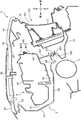
- FIG. 1 is a front view showing an interior structure of a vehicle front portion to which the present invention is applied.
- FIG. 2 is a perspective view of the interior structure.
- FIG. 3 is an exploded perspective view of the instrument panel. 4 is a schematic cross-sectional view taken along line IV-IV in FIG.
- FIG. 5 is a schematic cross-sectional view taken along the line VV of FIG. 6 is a schematic cross-sectional view taken along line VI-VI in FIG.
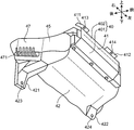
- FIG. 7 is a perspective view of the head-up display device.
- FIG. 8 is a perspective view of the head-up display device with the line-of-sight direction changed.
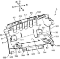
- FIG. 9 is a perspective view of the support member.
- FIG. 10 is a perspective view of the instrument panel reinforcement.
- FIG. 10 is a perspective view of the instrument panel reinforcement.
- FIG. 11 is a schematic cross-sectional view taken along line XI-XI in FIG.
- FIG. 12 is a perspective view showing an air conditioning duct and a support member.
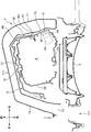
- FIG. 13 is a perspective view showing an air conditioning duct, a supporting member, and a head-up display device.
- FIG. 1 is a front view showing a front portion of an interior structure of a vehicle 1 to which the present invention is applied
- FIG. 2 is a perspective view of the interior structure.
- the front window 10 and the instrument panel 11 are extracted from the interior structure.
- FIG. 3 is an exploded perspective view of the instrument panel 11.
- “front” and “rear” arrows in the front-rear direction of the vehicle 1 “left” and “right” arrows in the vehicle width direction, and “up” and “ The “down” arrow is appended.
- the “front”, “rear”, “up”, “lower”, “left”, and “right” arrows in the following figures follow the direction indications of FIGS.
- the instrument panel 11 is disposed below the front window 10 and extends substantially over the entire width in the vehicle width direction (left-right direction).
- the instrument panel 11 includes an instrument panel body 12, a facing cover 13, and a top cover 14.
- the instrument panel main body 12 has a left and right width corresponding to the vehicle width, and is molded of a hard resin having a plurality of frame portions for accommodating instruments, air conditioning related parts, navigation systems, audios, etc. mounted on the vehicle 1. It is a member made of goods. From the center of the instrument panel body 12 in the left-right direction, a console portion 121 that divides the driver seat and the passenger seat hangs downward.
- the facing cover 13 and the top cover 14 are made of urethane foam or the like, and are members that form the surface layer portion of the instrument panel 11.
- the facing cover 13 covers the surface of the instrument panel 11 that faces the seat.
- the upper surface cover 14 covers the upper surface of the instrument panel 11, that is, the surface facing the front window 10.
- the instrument panel reinforcement 3 that extends horizontally in the left-right direction is disposed below the instrument panel 11.
- the instrument panel reinforcement 3 is made of a highly rigid metal cylinder, and is fixed to a vehicle body frame (not shown) at both left and right ends thereof. The lower surface of the instrument panel 11 is supported by the instrument panel reinforcement 3.
- the instrument panel 11 and the head-up display device 4 are assembled to the left side (driver's seat side) of the instrument panel 11.
- the meter panel 2 is a panel unit that is assembled to the instrument panel 11 so as to face the driver's seat and includes an analog or digital display unit such as a vehicle speed meter or a fuel gauge.
- the HUD device 4 is supported by the support member 5 in the instrument panel 11.
- the HUD device 4 is a unit having a housing structure, and projects a wide variety of information on the front window 10.
- the information is, for example, driving support information such as the traveling speed of the host vehicle, the speed limit information of the traveling section, a warning sign, and an instruction arrow for navigation.
- the HUD device 4 generates a projection image of the information and projects it toward the front window 10. A virtual image of the projected image reflected by the front window 10 is created in front of the driver's line of sight.
- the housing of the HUD device 4 includes a projection light source 4A (see FIG. 11) including, for example, an LED matrix and a TFT color display, and a mirror that reflects the light emitted from the projection light source 4A.
- a projection light source 4A see FIG. 11
- the instrument panel 11 and the front window 10 are close to each other, and a sufficient optical path length for making a projection image of a predetermined size cannot be obtained between them. For this reason, a plurality of mirrors are arranged inside the casing, and a necessary optical path length is ensured by reflecting projected light in multiple stages.
- the projection range of the light beam by the HUD device 4 is naturally expanded. Since it is necessary to increase the optical path length in order to create a projection image with a large display size, the housing size of the HUD device 4 increases and the weight thereof also increases.
- the instrument panel main body 12 (instrument panel 11) has an upper opening 122 for projection of the HUD device 4 on its upper surface and a surface facing the seat (a surface facing the rear side of the vehicle 1) for attaching the meter panel 2. And a side opening 123.
- the upper opening 122 is a rectangular opening facing the front window 10, and the projection light beam of the HUD device 4 passes through the upper opening 122 toward the front window 10.
- the size of the upper opening 122 is smaller than the size of the housing 40 (see FIGS. 7 and 8) of the HUD device 4. That is, in the completed state of the vehicle 1, the HUD device 4 cannot be taken out from the instrument panel 11 through the upper opening 122.
- the side opening 123 has a size capable of fitting the long meter panel 2 in the left-right direction. Since the meter panel 2 is larger than the HUD device 4, the side opening 123 has a size that allows the housing of the HUD device 4 to pass through. That is, in the completed state of the vehicle 1, the HUD device 4 can be taken out from the instrument panel 11 through the side opening 123.
- the meter cover 15 is fitted into the side opening 123, and the opening cover 16 is fitted into the upper opening 122, respectively.
- the meter cover 15 includes an opening 151 that exposes the display surface of the meter panel 2, and the instrument panel body 12 seats so as to cover the peripheral portion of the meter panel 2 in a state where the meter panel 2 is fitted in the side opening 123. It is attached to the opposite surface.
- the opening cover 16 includes a rectangular projection opening 161, and is attached to the upper surface of the instrument panel body 12 so as to cover the upper surface of the HUD device 4.
- an air conditioning duct 7 (see FIGS. 11 to 13), which will be described later, is disposed inside the instrument panel 11. Air-conditioned air flowing through the air-conditioning duct 7 is blown out into the vehicle compartment through the surface of the instrument panel 11.
- the instrument panel 11 as the air-conditioning air outlet has a left outlet 171 disposed on the driver's seat side, a middle outlet 172 disposed above the console unit 121, and a right outlet disposed on the passenger seat side.
- a mouth 173 is provided.
- FIG. 4 to 6 show a cross-sectional structure of the instrument panel 11 in the front-rear direction in a portion where the HUD device 4 is assembled.
- 4 to 6 are schematic cross-sectional views taken along lines IV-IV, VV and VI-VI in FIG. 1, respectively.
- an instrument panel 11 is disposed below the front window 10, and the instrument panel reinforcement 3 supports the instrument panel 11 from below.
- the HUD device 4 is assembled to the instrument panel 11 while being supported by the support member 5 between the front window 10 and the instrument panel reinforcement 3.
- the size of the HUD device 4 in the front-rear direction is larger than the interval between the front edge 122F and the rear edge 122R of the upper opening 122. The same applies to the horizontal size of the HUD device 4. For this reason, even if the opening cover 16 is removed, the HUD device 4 cannot be taken out from the instrument panel 11 as described above. In the present embodiment, even if the upper opening 122 has a size larger than that of the HUD device 4, the HUD device 4 cannot be taken out from above due to being obstructed by the front window 10.
- FIG. 7 is a perspective view of the HUD device 4
- FIG. 8 is a perspective view of the HUD device 4 in which the viewing direction is changed.
- the HUD device 4 includes a housing 40 that houses an optical system such as a projection light source 4A and a mirror.
- the housing 40 includes a main body 401 having an upper surface opening on which the projection light source A and the optical system are installed, and a lid body 402 that closes the opening of the main body 401.
- the top surface of the lid 402 is provided with a translucent window that allows projection light to pass therethrough.
- the housing 40 has a substantially flat rectangular parallelepiped shape, and includes a front surface 41, a lower surface 42, a rear surface 43, an upper surface 44, a right surface 45, and a left surface 46.
- An upper right bracket 411 and an upper left bracket 412 extend upward from the left and right ends of the upper end edge of the front surface 41, respectively.
- These brackets 411 and 412 have fixing holes 413 and 414, respectively, and serve as a fixing portion of the housing 40 to the support member 5.
- a lower right bracket 421 and a lower left bracket 422 extend downward.
- These brackets 421 and 422 have fixing holes 423 and 424, respectively, and serve as a fixing portion of the housing 40 to the instrument panel body 12.
- the lower right bracket 421 protrudes downward longer than the lower left bracket 422.
- FIG. 11 is a schematic cross-sectional view taken along line XI-XI in FIG.
- a projection light source 4 ⁇ / b> A and a heat sink 4 ⁇ / b> B are housed near the rear of the right surface 45 of the housing 40.
- the projection light source 4A is driven to perform a light emission operation by a driver (not shown), and generates heat by performing the light emission operation.
- the heat sink 4B dissipates heat generated by the projection light source 4A.
- the outer peripheral surface of the housing 40 adjacent to the heat sink 4B is a heat radiating portion 47.
- the heat received by the heat sink 4B by heat exchange with the projection light source 4A is dissipated outside the housing 40 through the heat radiating portion 47.
- a plurality of slits 471 are formed in the lower region of the wall surface of the heat radiating portion 47, and a plurality of pores 472 are formed in the upper region. The slits 471 and the pores 472 contribute to enhancing the heat dissipation effect in the heat dissipation part 47.
- FIG. 9 is a perspective view of the support member 5.
- the support member 5 is an L-shaped member having a front wall 51 and a lower wall 52 in a cross section in the front-rear direction.
- an upper flange portion 53 made of a belt-like flat portion that is long in the left-right direction is projected upward.
- a lower flange portion 54 which is similarly formed of a belt-like flat portion that is long in the left-right direction, projects downward.
- the front wall 51 is a wall facing the front surface 41 of the housing 40
- the lower wall 52 is a wall facing the lower surface 42.
- the height position of the upper flange portion 53 is set so that the upper flange portion 53 exists at a position higher than the upper end of the front surface 41 of the housing 40 (the front end of the upper surface 44) in a state where the HUD device 4 is supported by the support member 5. Has been. Therefore, an operator who handles a tool such as a screwdriver can access the upper flange portion 53 through the upper opening 122 by removing the opening cover 16.
- the upper flange portion 53 is provided with a pair of left and right fixing holes 531 serving as a fixing portion to the upper portion of the instrument panel body 12 and a pair of left and right support holes 532 serving as a fixing portion for the HUD device 4.
- a pair of left and right fixing holes 541 serving as a fixing portion for the instrument panel reinforcement 3 are disposed.
- Rectangular windows 521 are provided at positions in front of the pair of fixing holes 541 in the lower wall 52.
- a locking piece 522 having a hook shape protrudes downward from the front edge of the window 521.
- a support hole 542 serving as a fixing portion for the HUD device 4 is disposed near the left end of the lower flange portion 54.
- the support member 5 further includes a left wall 55 and a right wall 56.
- the left wall 55 and the right wall 56 are walls that block the left and right surfaces of the front wall 51 and the lower wall 52, respectively.
- the distance between the left wall 55 and the right wall 56 is wider than the left and right width of the HUD device 4.
- the housing 40 of the HUD device 4 is configured to be mostly accommodated in a space defined by the front wall 51, the lower wall 52, the left wall 55, and the right wall 56, and the upper surface 44 and the rear surface 43 are support members. 5 is placed on the support member 5 in a manner that does not interfere with the support member 5.
- the right wall 56 is provided with a notch 561 formed by notching a rear portion of the right wall 56.
- the air conditioning duct 7 is disposed so as to surround the side of the support member 5, and a part of the air conditioning duct 7 (facing portion) is also formed outside the right wall 56. 75) is disposed.
- the notch 561 is an opening for preventing heat exchange between the heat radiating portion 47 of the HUD device 4 and the part of the air conditioning duct 7.
- a pair of left and right engaging portions 57 are disposed at the lower end portion of the front wall 51.
- the locking portion 57 is a rectangular flat plate portion in which a part of the front wall 51 is shallowly recessed.
- a screw hole 571 serving as a fixing portion for the instrument panel reinforcement 3 is formed in the locking portion 57.
- the middle extension portion 581 is a flat plate portion extending in the left-right direction extending downward from the center in the left-right direction of the lower flange portion 54, and a pair of left and right fixing holes 584 are perforated.
- the fixing hole 584 serves as a fixing portion for the lower portion of the instrument panel main body 12 of the support member 5.
- the left extending portion 582 is a flat plate portion extending downward from the left end of the lower flange portion 54, and similarly has a fixing hole 585 serving as a fixing portion to the lower portion of the instrument panel main body 12.
- the right extending portion 583 is a small flat plate portion extending downward from the right end of the lower flange portion 54, and has a support hole 586 that is also a fixing portion for the instrument panel main body 12.
- FIG. 10 is a perspective view of the main part of the instrument panel reinforcement 3.
- An instrument panel support bracket 31 and a support piece 32 are attached to the outer peripheral surface of the instrument panel reinforcement 3.
- the instrument panel support fitting 31 is a fitting for connecting the lower surface of the instrument panel 11 and the instrument panel reinforcement 3. By this connection, the instrument panel 11 is supported by the highly rigid instrument panel reinforcement 3 that is firmly supported by a vehicle body frame (not shown).
- the support pieces 32 are attached to the outer peripheral surface of the instrument panel reinforcement 3 as a pair on the left and right of the instrument panel support fitting 31.
- the support piece 32 is a metal fitting that connects the support member 5 and the instrument panel reinforcement 3 in order to support the support member 5 that supports the HUD device 4 with the instrument panel reinforcement 3.
- Each support piece 32 is provided with a support hole 321.
- the support member 5 is supported by the instrument panel reinforcement 3 via the support bracket 6 described below.
- the support bracket 6 is a plate-like member that extends in the front-rear direction of the vehicle 1 below the HUD device 4.
- the support bracket 6 includes a horizontal portion 61 along the lower surface of the lower wall 52 of the support member 5, a front end portion 62 on the vehicle front side, and a rear end portion 63 on the vehicle rear side.
- the support rigidity of the HUD device 4 can be further enhanced by the interposition of the support bracket 6.
- a pair of left and right are incorporated at positions corresponding to the pair of left and right engaging portions 57 of the support member 5.
- the front end 62 is a portion fixed to the front wall 51 of the support member 5.
- the front end portion 62 is a rising portion that is bent upward from the front end of the horizontal portion 61, and extends upward along the front wall 51 so as to overlap the locking portion 57. That is, the support bracket 6 has a shape that wraps around from the lower side of the lower wall 52 of the support member 5 to the front side of the front wall 51.
- the rear end portion 63 is a portion fixed to the instrument panel reinforcement 3 together with the lower flange portion 54.
- the rear end portion 63 is a portion bent downward from the rear end of the horizontal portion 61, and is sandwiched between the support piece 32 of the instrument panel reinforcement 3 and the lower flange portion 54 of the support member 5.
- FIG. 12 is a perspective view showing the left side portion of the instrument panel reinforcement 3, the support member 5, and the air conditioning duct 7.
- FIG. The air conditioning duct 7 will be described later.
- the front end portion 62 of the support bracket 6 is superimposed on the outer surface of the locking portion 57 of the support member 5 in the front-rear direction.
- the front end portion 62 is provided with a through hole, and the locking portion 57 and the front end portion 62 are aligned so that the through hole and the screw hole 571 of the locking portion 57 overlap each other.
- a first fixing screw S1 is inserted through the through hole and screw hole 571, and the support member 5 and the support bracket 6 are fixed.
- the rear end portion 63 of the support bracket 6 is also provided with a through hole.
- the support piece 32, the rear end portion 63, and the lower flange so that the through hole overlaps the support hole 321 provided in the support piece 32 of the instrument panel reinforcement 3 and the fixing hole 541 provided in the lower flange portion 54 of the support member 5.
- the part 54 is overlapped in the front-rear direction.
- a second fixing screw S ⁇ b> 2 is inserted through the through hole, the support hole 321, and the fixing hole 541, and the support member 5 and the support bracket 6 are fixed to the instrument panel reinforcement 3.
- the horizontal portion 61 is provided with a window portion 611.
- a locking piece 522 of the support member 5 is fitted into the front edge of the window portion 611.
- the air conditioning duct 7 is a duct for supplying heating, cooling, or dehumidified conditioned air generated by an air conditioning device (not shown) included in the vehicle 1 to the vehicle interior.
- FIG. 13 is a perspective view showing an arrangement relationship between the air conditioning duct 7, the HUD device 4, and the support member 5. Referring to FIGS. 11 to 13, the air conditioning duct 7 includes a portion disposed inside the instrument panel 11 and includes an upstream portion 71 and a downstream portion 72 around the support member 5.
- the upstream portion 71 and the downstream portion 72 are duct portions for guiding the conditioned air to the left duct end 73.
- the left duct end 73 is provided at the end of the downstream portion 72 and communicates with a left outlet 171 provided near the left end of the instrument panel 11.
- 12 and 13 also show a middle duct end 74 through which conditioned air is guided by another duct portion.
- the middle duct end 74 communicates with a middle outlet 172 provided in the console portion 121.
- the upstream part 71 and the downstream part 72 of the air conditioning duct 7 extend in the horizontal direction so as to bypass the side surface of the support member 5, that is, the side surface of the housing 40 of the HUD device 4.
- the upstream portion 71 faces the right surface 45 (first side surface) of the housing 40 and the right wall 56 of the support member 5 in the left-right direction.
- the downstream portion 72 opposes the left surface 46 (second side surface) facing each other in the vehicle width direction with the right surface 45 and the left and right sides with the left wall 55 interposed therebetween.
- the detour portion 711 that is a duct connecting the upstream portion 71 and the downstream portion 72 is opposed in the front-rear direction across the front surface 41 and the front wall 51.
- the upstream portion 71 is along relatively close to the right surface 45.
- the downstream portion 72 passes through the vicinity of the left surface 46, but is relatively separated from the left surface 46.
- the upstream portion 71 along the right surface 45 of the housing 40 includes a facing portion 75 facing the heat radiating portion 47 disposed on the rear side of the right surface 45 so as to be able to exchange heat.
- the upstream portion 71 is juxtaposed on the right surface 45 so that the facing portion 75 faces the heat radiating portion 47 with a predetermined gap G therebetween.
- the notch 561 in the right wall 56 of the support member 5 is provided so as not to hinder heat exchange between the facing portion 75 and the heat radiating portion 47.
- the temperature of the heat medium (air conditioning air) flowing through the air conditioning duct 7 is at most 30 ° C. or less even in the case of heating operation.
- the temperature of the air-conditioning air is sufficiently lower than the temperature of heat generated by the projection light source 4A. Therefore, when the heat of the projection light source 4A is dissipated from the heat radiating portion 47 through the heat sink 4B, this heat is absorbed by the air-conditioning air that passes through the facing portion 75 toward the left duct end 73. Therefore, the HUD device 4 can dissipate heat well.
- the facing portion 75 is a flat portion that is closest to the HUD device 4 (housing 40) in the air conditioning duct 7.
- the gap G can be about several mm to 20 mm.
- the gap G is too small, or when the facing portion 75 is in contact with the heat radiating portion 47, it is preferable from the viewpoint of heat exchange, but when the vehicle 1 is vibrated, the vibration is transmitted to the HUD device 4. There is a concern that vibration noise may occur in the facing portion or the projected image may fluctuate.
- the gap G is too large, the heat exchange efficiency between the facing portion 75 and the heat radiating portion 47 is lowered, so that there is a tendency that the HUD device 4 cannot sufficiently radiate heat.
- the lower right bracket 421 is in front of the right extending portion 583, and the support plate portion 124 of the instrument panel body 12, and the lower left bracket 422 is in front of the left portion of the lower flange portion 54. Overlapping in the direction.
- the fixing hole 423 of the lower right bracket 421 and the screw hole of the support plate portion 124 are aligned, and both are fastened by the third fixing screw S3.
- FIG. 6 is a cross-sectional view of a fixed portion of the lower right bracket 421 by the third fixing screw S3.
- the fixing hole 424 of the lower left bracket 422 and the support hole 542 of the lower flange portion 54 are aligned, and both are fastened by the third fixing screw S3.
- the HUD device 4 is attached to and detached from the instrument panel body 12 through the side opening 123.
- the upper flange portion 53 extends higher than the upper end of the front surface 41 of the housing 40.
- the upper right and upper left brackets 411 and 412 are portions protruding upward from the housing 40. Therefore, in a state where the opening cover 16 is removed, the operator can perform the fastening operation of the fourth fixing screw S4 through the upper opening 122. Further, in a state where the meter panel 2 and the meter cover 15 are removed, the operator can perform the fastening operation of the third fixing screw S3 through the side opening 123.
- the operator When removing the HUD device 4 from the instrument panel 11, the operator first removes the opening cover 16, the meter panel 2, and the meter cover 15 from the instrument panel body 12. Thereafter, the worker accesses from the upper opening 122 to remove the fourth fixing screw S4, and accesses from the side opening 123 to remove the third fixing screw S3. Thereafter, the HUD device 4 is taken out through the side opening 123.
- the HUD device 4 includes a heat radiating portion 47 on the right surface 45 of the housing 40, and the air conditioning duct 7 includes a facing portion 75 that faces the heat radiating portion 47 so as to be able to exchange heat.
- circulates the inside of the air-conditioning duct 7 absorb the heat which the thermal radiation part 47 emits, and can thermally radiate the heat
- the air-conditioning duct 7 is incorporated in the instrument panel 11 of a general vehicle 1 as an instrument panel duct or the like for blowing air-conditioned air from the instrument panel 11 toward the vehicle interior. Therefore, it is not necessary to newly add a cooling function component for cooling the HUD device 4.
- the facing portion 75 faces the heat radiating portion 47 with a predetermined gap G therebetween. That is, it is set as the structure which both do not contact
- the facing portion 75 is arranged in parallel on the right surface 45 provided with the heat radiating portion 47. That is, the facing portion 75 is arranged side by side to the side of the heat radiating portion 47. Therefore, even if dew condensation occurs in the air conditioning duct 7, the dew condensation water does not drop onto the housing 40 of the HUD device 4.
- the housing 40 of the HUD device 4 includes a right surface 45 (first side surface) and a left surface 46 (second side surface) that face each other in the vehicle width direction, and the heat radiating portion 47 is disposed on the right surface 45.
- the air conditioning duct 7 includes an upstream portion 71 having a facing portion 75 along the right surface 45, a downstream portion 72 passing through the vicinity of the left surface 46, and a left duct end 73 (outlet) provided at the end of the downstream portion 72.
- heat exchange between the heat radiating portion 47 and the facing portion 75 is not performed in the downstream portion 72 where the left duct end 73 is disposed, but the upstream portion 71 spaced from the downstream portion 72 upstream in the air-conditioning air flow direction.
- the heat exchange is performed in Therefore, the influence of the heat exchange on the controlled air-conditioning air can be avoided. For example, it is possible to prevent the warm air of the heat exchange from being mixed with the cooling air just before being blown out from the left duct end 73.
- the interior structure described above includes a support member 5 that is incorporated in the instrument panel 11 and that supports the HUD device 4 in a fixed manner. Thereby, even the heavy HUD device 4 can be firmly supported by the support member 5. Further, the support member 5 has a notch 561 at a portion where the heat radiating portion 47 and the facing portion 75 face each other. For this reason, heat exchange between the heat radiating portion 47 and the facing portion 75 is not hindered.
- the facing portion 75 faces the heat radiating portion 47 with a predetermined gap G is shown.
- the facing portion 75 and the heat radiating portion 47 may be in contact with each other. In this case, it is desirable to firmly fix the housing 40 of the HUD device 4 and the air conditioning duct 7 so as not to generate vibration noise.
- a cushioning spacer member having excellent heat conductivity may be interposed in the gap G.
- a heat receiving member such as a metal sheet may be attached or wound around the facing portion 75 so that the radiant heat from the heat radiating portion 47 can be absorbed easily.
- the facing portion 75 is a flat plate portion provided in the air conditioning duct 7 .
- the shape of the facing portion 75 is desirably matched to the shape of the outer surface of the heat radiating portion 47.
- the facing portion 75 is preferably concave.
- An interior structure of a vehicle includes an instrument panel disposed below a front window, an air-conditioning duct disposed inside the instrument panel, and a housing structure, and the instrument A head-up display device that is assembled to a panel and projects information on the front window, the head-up display device includes a heat radiating portion on an outer peripheral surface of the housing, and the air conditioning duct includes the heat radiating portion and It is provided with facing parts that face each other so that heat exchange is possible.
- casing of a head-up display apparatus can be thermally radiated favorably with the heat medium (air-conditioning air) which distribute
- the air conditioning duct is incorporated in an instrument panel of a general vehicle as an instrument panel duct or the like for blowing air-conditioned air from the instrument panel toward the vehicle interior. Therefore, it is not necessary to add a new cooling function component.
- the facing portion is opposed to the heat radiating portion with a predetermined gap.
- the housing includes a side surface, the heat radiating portion is disposed on the side surface, and the facing portion is arranged in parallel with the side surface provided with the heat radiating portion.
- the facing portion is arranged side by side on the side of the heat radiating portion. Therefore, even if dew condensation occurs in the air conditioning duct, the dew condensation water does not drop onto the casing of the head-up display device.
- the housing includes a first side surface and a second side surface facing each other in the vehicle width direction of the vehicle, and a side surface on which the heat radiating portion is disposed is the first side surface
- the air conditioning duct Comprises an upstream portion that has the facing portion and extends along the first side surface, a downstream portion that passes through the vicinity of the second side surface, and a blowout port provided at the end of the downstream portion.
- heat exchange is not performed with the heat dissipating part of the head-up display device in the downstream part in which the air outlet of the air conditioning duct is disposed, but in the upstream part separated from the downstream part.
- the Therefore, the influence of the heat exchange on the controlled air-conditioning air can be avoided. For example, it is possible to prevent the warm air of the heat exchange from being mixed with the cooling air just before being blown out from the outlet.
- the interior structure includes a support member that is incorporated in the instrument panel and fixedly supports the head-up display device in a state in which the head-up display device is accommodated, and the heat dissipation portion and the facing portion face each other. It is desirable to have a notch in the part.
- the support member has a notch part, it does not inhibit the heat exchange between the said thermal radiation part and the said facing part.
Landscapes
- Engineering & Computer Science (AREA)
- Mechanical Engineering (AREA)
- Physics & Mathematics (AREA)
- Chemical & Material Sciences (AREA)
- Combustion & Propulsion (AREA)
- Transportation (AREA)
- Thermal Sciences (AREA)
- General Physics & Mathematics (AREA)
- Optics & Photonics (AREA)
- Multimedia (AREA)
- Signal Processing (AREA)
- Instrument Panels (AREA)
- Air-Conditioning For Vehicles (AREA)
Abstract
車両の内装構造は、フロントウィンドゥの下方に配置されるインストルメントパネルと、前記インストルメントパネルの内部に配設される空調ダクトと、筐体構造を備え、前記インストルメントパネルに組み付けられ、前記フロントウィンドゥに情報を投影するヘッドアップディスプレイ装置とを備える。前記ヘッドアップディスプレイ装置は、前記筐体の外周面に放熱部を備える。前記空調ダクトは、前記放熱部と熱交換可能に対向する対面部を備える。
Description
本発明は、ヘッドアップディスプレイ装置を備えた車両の内装構造に関する。
近年、自動車等の車両においては、インストルメントパネルにヘッドアップディスプレイ(HUD)装置が組み込まれるようになりつつある(例えば特許文献1)。HUD装置は、運転者の運転時における視線方向に配置されたコンバイナ若しくはフロントウィンドゥ自体に、運転者に有益な情報(画像)を投影する。投影された画像はフロントウィンドゥで反射され、虚像を作る。運転者は、車両前方の風景に前記虚像を重ねて視認することになる。
一般にHUD装置は筐体構造を備え、その筐体内に投影光線を発する投影光源を有する。光源は、発光動作によって発熱する。このため、HUD装置に放熱部を具備させ、当該放熱部を通して筐体内の熱を外部に放熱させることが知られている。
フロントウィンドゥに多種多様な情報を投影する場合、自ずとHUD装置による光線の投影範囲が拡張する。表示サイズの大きい投影画像を作るには、投影光源からフロントウィンドゥまでの光路長を長くする必要がある。インストルメントパネルとフロントウィンドゥとは近接しており、両者間では光路長を稼げないことから、HUD装置の筐体内において投影光線を反射するミラーを配置するなどして、光路長を確保せねばならない。このため、HUD装置は、大サイズ、大重量のユニットになる傾向がある。
しかし、インストルメントパネルの内部は構造的に熱が籠もり易く、HUD装置の前記放熱部による放熱効果が減殺されてしまう懸念がある。また、冷却ファンのような冷却機能部品を付設することも考えられるが、大サイズのHUD装置をインストルメントパネルに組み付けた場合、狭小なインストルメントパネル内にそのような冷却機能部品を追加配置することは困難である。
本発明の目的は、インストルメントパネルに組み付けられるヘッドアップディスプレイ装置の放熱性を、冷却機能部品を追加することなく良好にすることにある。
本発明の一局面に係る車両の内装構造は、フロントウィンドゥの下方に配置されるインストルメントパネルと、前記インストルメントパネルの内部に配設される空調ダクトと、筐体構造を備え、前記インストルメントパネルに組み付けられ、前記フロントウィンドゥに情報を投影するヘッドアップディスプレイ装置と、を備え、前記ヘッドアップディスプレイ装置は、前記筐体の外周面に放熱部を備え、前記空調ダクトは、前記放熱部と熱交換可能に対向する対面部を備えることを特徴とする。
[車両の内装構造の概略]
以下、図面に基づいて、本発明の実施形態につき詳細に説明する。図1は、本発明が適用される車両1の内装構造の前方部分を示す正面図、図2は、前記内装構造の斜視図である。これらの図では、内装構造における、フロントウィンドゥ10及びインストルメントパネル11の部分を抜き出して図示している。図3は、インストルメントパネル11の分解斜視図である。なお、これらの図中には、車両1の前後方向における「前」及び「後」の矢印、車幅方向における「左」及び「右」の矢印、並びに、車高方向における「上」及び「下」の矢印を付記している。以下の図に付している「前」「後」「上」「下」「左」「右」の矢印は、図1~図3の方向表示に従っている。
以下、図面に基づいて、本発明の実施形態につき詳細に説明する。図1は、本発明が適用される車両1の内装構造の前方部分を示す正面図、図2は、前記内装構造の斜視図である。これらの図では、内装構造における、フロントウィンドゥ10及びインストルメントパネル11の部分を抜き出して図示している。図3は、インストルメントパネル11の分解斜視図である。なお、これらの図中には、車両1の前後方向における「前」及び「後」の矢印、車幅方向における「左」及び「右」の矢印、並びに、車高方向における「上」及び「下」の矢印を付記している。以下の図に付している「前」「後」「上」「下」「左」「右」の矢印は、図1~図3の方向表示に従っている。
インストルメントパネル11は、フロントウィンドゥ10の下方に配置され、概ね車幅方向(左右方向)全幅に亘って延びている。インストルメントパネル11は、インパネ本体12、対面カバー13及び上面カバー14を含む。インパネ本体12は、車幅に対応する左右幅を有し、車両1に装備される計器類、空調関連部品、ナビゲーションシステム、オーディオ類などを収容する複数の枠部分を備えた、硬質樹脂の成型品からなる部材である。インパネ本体12の左右方向中央からは、運転席と助手席とを区画するコンソール部121が、下方に垂下している。
対面カバー13及び上面カバー14は、ウレタン発泡材等からなり、インストルメントパネル11の表層部を形成する部材である。対面カバー13は、インストルメントパネル11の座席に対向する面を覆っている。上面カバー14は、インストルメントパネル11の上面、つまり、フロントウィンドゥ10と対向する面を覆っている。
インストルメントパネル11の下方には、左右方向に水平に延びるインパネレインフォース3が配置されている。インパネレインフォース3は、高剛性の金属製円筒体からなり、その左右両端において車体フレーム(図示せず)に固定されている。インストルメントパネル11の下面が、このインパネレインフォース3によって支持されている。
図3に示されているように、インストルメントパネル11の左方側(運転席側)には、メーターパネル2及びヘッドアップディスプレイ装置4(以下、HUD装置4)が組み付けられている。メーターパネル2は、運転席に対向するようにインストルメントパネル11に組み付けられ、車速メーターや燃料計などのアナログ又はデジタル表示部を備えたパネルユニットである。後記で詳述するが、HUD装置4は、インストルメントパネル11内において支持部材5によって支持されている。
HUD装置4は、筐体構造を備えたユニットであり、フロントウィンドゥ10に多種多様な情報を投影する。前記情報は、例えば自車の走行速度、走行区間の速度制限情報、警告標識、ナビゲーション用の指示矢印などの、運転支援情報である。HUD装置4は、これら情報の投影画像を生成し、フロントウィンドゥ10に向けて投影する。運転者の視線前方には、フロントウィンドゥ10で反射された投影画像の虚像が作られる。
HUD装置4の筐体内部には、例えばLEDマトリックス及びTFTカラーディスプレイを含む投影光源4A(図11参照)と、この投影光源4Aが発する光線を反射するミラーとが内蔵されている。通常、インストルメントパネル11とフロントウィンドゥ10とは近接しており、両者間では所定サイズの投影画像を作るための十分な光路長を稼げない。このため、前記筐体内部には複数のミラーが配置され、投影光線を多段反射させることによって、必要な光路長を確保している。フロントウィンドゥ10に多種多様な情報を投影させようとすると、自ずとHUD装置4による光線の投影範囲が拡張する。表示サイズの大きい投影画像を作るには光路長を長く取る必要があることから、HUD装置4の筐体サイズが大きくなり、その重量も大きくなる。
インパネ本体12(インストルメントパネル11)は、その上面にHUD装置4の投影用の上方開口122と、座席に対向する面(車両1の後方側に向いた面)にメーターパネル2の取り付け用の側方開口123とを備えている。上方開口122は、フロントウィンドゥ10に対向した矩形の開口であり、HUD装置4の投影光線はこの上方開口122を通過してフロントウィンドゥ10に向かう。なお、上方開口122のサイズは、HUD装置4の筐体40(図7、図8参照)のサイズよりも小さいサイズである。つまり、車両1の完成状態では、インストルメントパネル11からHUD装置4を、上方開口122を通して取り出すことはできない。
側方開口123は、左右方向に長いメーターパネル2を嵌め込むことが可能なサイズを有する。メーターパネル2は、HUD装置4よりも大サイズであるため、側方開口123はHUD装置4の筐体を通過させ得るサイズを有する。すなわち、車両1の完成状態において、インストルメントパネル11からHUD装置4を、側方開口123を通して取り出すことができる。
側方開口123にはメーターカバー15が、上方開口122には開口カバー16が各々嵌め込まれる。メーターカバー15は、メーターパネル2の表示面を露出させる開口151を備え、メーターパネル2が側方開口123に嵌め込まれた状態で、メーターパネル2の周縁部分を覆うように、インパネ本体12の座席対向面に取り付けられている。開口カバー16は、矩形の投射開口161を備え、HUD装置4の上面を覆うように、インパネ本体12の上面に取り付けられている。
インストルメントパネル11の内部には、後述する空調ダクト7(図11~図13参照)が配設されている。空調ダクト7を流通する空調エアは、インストルメントパネル11の表面を通して車室内に吹き出される。前記空調エアの吹き出し口としてインストルメントパネル11には、運転席側に配置された左吹き出し口171、コンソール部121の上方に配置された中吹き出し口172、及び助手席側に配置された右吹き出し口173が備えられている。
[HUD装置の支持構造]
続いて、インストルメントパネル11内におけるHUD装置4の支持構造について詳述する。図4~図6は、HUD装置4が組み付けられた部分における、インストルメントパネル11の前後方向の断面構造を示している。図4、図5及び図6は、それぞれ図1のIV-IV線、V-V線及びVI-VI線の概略的な断面図である。
続いて、インストルメントパネル11内におけるHUD装置4の支持構造について詳述する。図4~図6は、HUD装置4が組み付けられた部分における、インストルメントパネル11の前後方向の断面構造を示している。図4、図5及び図6は、それぞれ図1のIV-IV線、V-V線及びVI-VI線の概略的な断面図である。
図4に示されている通り、フロントウィンドゥ10の下方にインストルメントパネル11が配置され、このインストルメントパネル11をインパネレインフォース3が下方から支えている。HUD装置4は、フロントウィンドゥ10とインパネレインフォース3との間において、支持部材5で支持された状態でインストルメントパネル11に組み付けられている。
HUD装置4の前後方向のサイズは、上方開口122の前縁122Fと後縁122Rとの間の間隔よりも大きい。HUD装置4の左右方向のサイズも同様である。このため、開口カバー16を取り外しても、既述の通りHUD装置4をインストルメントパネル11から上方へ取り出すことはできない。なお、本実施形態では、たとえ上方開口122がHUD装置4よりも大きなサイズを有していても、フロントウィンドゥ10に阻害されてHUD装置4を上方から取り出すことができない。
<HUD装置の筐体>
図7は、HUD装置4の斜視図、図8は、視線方向を変えた、HUD装置4の斜視図である。HUD装置4は、投影光源4A及びミラーなどの光学系を収容する筐体40を備える。筐体40は、投影光源A及び前記光学系が据え付けられる上面開口の本体401と、この本体401の開口を塞ぐ蓋体402とからなる。蓋体402の天面には、投影光線を通過させる透光性の窓部が備えられている。
図7は、HUD装置4の斜視図、図8は、視線方向を変えた、HUD装置4の斜視図である。HUD装置4は、投影光源4A及びミラーなどの光学系を収容する筐体40を備える。筐体40は、投影光源A及び前記光学系が据え付けられる上面開口の本体401と、この本体401の開口を塞ぐ蓋体402とからなる。蓋体402の天面には、投影光線を通過させる透光性の窓部が備えられている。
筐体40は、大略的に扁平な直方体の形状を有し、前面41、下面42、後面43、上面44、右面45及び左面46を備えている。前面41の上端縁の左右端部からは、それぞれ右上ブラケット411及び左上ブラケット412が上方に延出している。これらブラケット411、412は、それぞれ固定孔413、414を有しており、筐体40の支持部材5への固定部となる。下面42の後端縁(後面43の下端縁)の左右端部からは、それぞれ右下ブラケット421及び左下ブラケット422が下方に延出している。これらブラケット421、422は、それぞれ固定孔423、424を有しており、筐体40のインパネ本体12への固定部となる。右下ブラケット421は、左下ブラケット422よりも長く下方へ突出している。
右面45の後方部分には、筐体40内の熱を放熱する放熱部47が配置されている。ここで、図1のXI-XI線の概略的な断面図である図11を参照する。筐体40の右面45の後方付近には、投影光源4Aとヒートシンク4Bとが収容されている。投影光源4Aは、図略のドライバによって発光動作を行うよう駆動され、当該発光動作を行うことによって発熱する。ヒートシンク4Bは、投影光源4Aが発する熱を放散させる。
ヒートシンク4Bに隣接する筐体40の外周面が、放熱部47である。投影光源4Aとの熱交換によってヒートシンク4Bが受け取った熱は、放熱部47を通して筐体40の外部に放散される。放熱部47の壁面の下方領域には複数のスリット471が形成され、上方領域には複数の気孔472が穿孔されている。スリット471及び気孔472は、放熱部47における放熱効果を高めることに寄与する。
<支持部材>
支持部材5は、上方開口122の下方においてインストルメントパネル11に組み込まれ、HUD装置4を収容した状態で固定的に支持する。図9は、支持部材5の斜視図である。図9及び図5を主に参照して、支持部材5は、前壁51及び下壁52を有する、前後方向の断面でL字型の部材である。前壁51の上端には、左右方向に長い帯状の平面部からなる上フランジ部53が、上方に突設されている。下壁52の後端には、同様に左右方向に長い帯状の平面部からなる下フランジ部54が、下方に突設されている。
支持部材5は、上方開口122の下方においてインストルメントパネル11に組み込まれ、HUD装置4を収容した状態で固定的に支持する。図9は、支持部材5の斜視図である。図9及び図5を主に参照して、支持部材5は、前壁51及び下壁52を有する、前後方向の断面でL字型の部材である。前壁51の上端には、左右方向に長い帯状の平面部からなる上フランジ部53が、上方に突設されている。下壁52の後端には、同様に左右方向に長い帯状の平面部からなる下フランジ部54が、下方に突設されている。
前壁51は、筐体40の前面41に対向する壁であり、下壁52は下面42に対向する壁である。上フランジ部53は、支持部材5にHUD装置4が支持された状態で、筐体40の前面41の上端(上面44の前端)よりも高い位置に存在するように、その高さ位置が設定されている。従って、スクリュードライバー等の工具を扱う作業者は、開口カバー16を取り外すことによって、上方開口122を通して上フランジ部53にアクセス可能である。
上フランジ部53には、インパネ本体12の上方部分との固定部となる左右一対の固定孔531と、HUD装置4に対する固定部となる左右一対の支持孔532とが配置されている。下フランジ部54には、インパネレインフォース3に対する固定部となる左右一対の固定孔541が配置されている。下壁52の一対の固定孔541の前方の位置には、それぞれ矩形の窓部521が設けられている。窓部521の前縁には、フック形状を備えた係止片522が下方に突設されている。また、下フランジ部54の左端付近には、HUD装置4に対する固定部となる支持孔542が配置されている。
支持部材5は、さらに左壁55及び右壁56を含む。左壁55及び右壁56は、各々前壁51及び下壁52の左面及び右面を塞ぐ壁である。左壁55と右壁56との間の間隔は、HUD装置4の左右幅よりも広い。一方、支持部材5の上面及び後面には壁が存在していない。HUD装置4の筐体40は、前壁51、下壁52、左壁55及び右壁56によって区画される空間内に大半が収容される形態で、また、上面44及び後面43については支持部材5と干渉しない態様で、支持部材5上に載置されている。
右壁56には、当該右壁56の後方部分を切り欠いてなる切り欠き部561が設けられている。図11に示す通り、インストルメントパネル11内において、空調ダクト7が支持部材5の側方を取り囲むように配設されており、右壁56の外方にも空調ダクト7の一部(対面部75)が配設される。切り欠き部561は、HUD装置4の放熱部47と、空調ダクト7の前記一部との熱交換を阻害しないようにするための開口である。
前壁51の下端部には、左右一対の係止部57が配置されている。係止部57は、前壁51の一部を浅く凹没させた矩形状の平板部である。係止部57には、インパネレインフォース3に対する固定部となるネジ孔571が穿孔されている。
下フランジ部54の下縁からは、中延在部581、左延在部582及び右延在部583が下方に延びている。中延在部581は、下フランジ部54の左右方向中央から下方に延びる左右方向に長い平板部であり、左右一対の固定孔584が穿孔されている。この固定孔584は、支持部材5のインパネ本体12の下方部分への固定部となる。左延在部582は、下フランジ部54の左端から下方に延びる平板部であり、同様にインパネ本体12の下方部分への固定部となる固定孔585を有している。右延在部583は、下フランジ部54の右端から下方に延びる小さな平板部であり、同じくインパネ本体12に対する固定部となる支持孔586を有している。
<インパネレインフォース>
図10は、インパネレインフォース3の要部の斜視図である。インパネレインフォース3の外周面には、インパネ支持金具31及び支持片32が取り付けられている。インパネ支持金具31は、インストルメントパネル11の下面とインパネレインフォース3とを連結するための金具である。この連結によって、インストルメントパネル11は、図略の車体フレームで強固に支持された高剛性のインパネレインフォース3によって支持される。
図10は、インパネレインフォース3の要部の斜視図である。インパネレインフォース3の外周面には、インパネ支持金具31及び支持片32が取り付けられている。インパネ支持金具31は、インストルメントパネル11の下面とインパネレインフォース3とを連結するための金具である。この連結によって、インストルメントパネル11は、図略の車体フレームで強固に支持された高剛性のインパネレインフォース3によって支持される。
支持片32は、インパネ支持金具31の左右に一対で、インパネレインフォース3の外周面に取り付けられている。支持片32は、HUD装置4を支持する支持部材5をインパネレインフォース3で支持させるために、支持部材5とインパネレインフォース3とを連結させる金具である。各支持片32には、支持孔321が穿孔されている。本実施形態では、支持部材5は、次述の支持ブラケット6を介してインパネレインフォース3で支持される。
<支持ブラケット>
図5を参照して、支持ブラケット6は、HUD装置4の下方において車両1の前後方向に延びる板状部材である。支持ブラケット6は、支持部材5の下壁52の下面に沿う水平部61と、車両前方側の前端部62と、車両後方側の後端部63とを含む。支持ブラケット6の介在によって、HUD装置4の支持剛性を一層高めることができる。支持部材5の左右一対の係止部57に対応する位置に、左右一対で組み込まれている。
図5を参照して、支持ブラケット6は、HUD装置4の下方において車両1の前後方向に延びる板状部材である。支持ブラケット6は、支持部材5の下壁52の下面に沿う水平部61と、車両前方側の前端部62と、車両後方側の後端部63とを含む。支持ブラケット6の介在によって、HUD装置4の支持剛性を一層高めることができる。支持部材5の左右一対の係止部57に対応する位置に、左右一対で組み込まれている。
前端部62は、支持部材5の前壁51に対する固定される部分である。前端部62は、水平部61の前端から上方に折り曲げられた立ち上がり部分であり、前壁51に沿って係止部57と重なるように上方に延びている。すなわち、支持ブラケット6は、支持部材5の下壁52の下方から前壁51の前方へ回り込むような形状を備える。後端部63は、下フランジ部54と共にインパネレインフォース3に固定される部分である。後端部63は、水平部61の後端から下方に折り曲げられた部分であり、インパネレインフォース3の支持片32と支持部材5の下フランジ部54との間に挟まれている。
図5、図9、図10、図12を参照して、支持部材5の支持構造を説明する。図12は、インパネレインフォース3の左側部分と支持部材5、及び空調ダクト7を示す斜視図である。空調ダクト7については後述する。支持ブラケット6の前端部62は、支持部材5の係止部57の外面に前後方向に重ね合わされている。前端部62には貫通孔が備えられており、この貫通孔と係止部57のネジ孔571とが重なるように、係止部57と前端部62とが位置合わせされる。前記貫通孔及びネジ孔571に第1固定ネジS1が挿通され、支持部材5と支持ブラケット6とが固定されている。
支持ブラケット6の後端部63にも、貫通孔が備えられている。この貫通孔が、インパネレインフォース3の支持片32が有する支持孔321、並びに、支持部材5の下フランジ部54が有する固定孔541と重なるように、支持片32、後端部63及び下フランジ部54が前後方向に重ね合わされている。前記貫通孔、支持孔321及び固定孔541に第2固定ネジS2が挿通され、インパネレインフォース3に対して支持部材5及び支持ブラケット6が固定されている。さらに、図5に示されているように、水平部61には窓部611が備えられている。この窓部611の前縁に対し、支持部材5の係止片522が嵌め込まれている。
[空調ダクト]
空調ダクト7は、車両1が備える空調装置(図略)が発生する暖房、冷房或いは除湿の空調エアを車室内へ供給するためのダクトである。図13は、空調ダクト7と、HUD装置4及び支持部材5との配置関係を示す斜視図である。図11~図13を参照して、空調ダクト7はインストルメントパネル11の内部に配設される部分を含み、支持部材5の周辺において、上流部71と下流部72とを備える。
空調ダクト7は、車両1が備える空調装置(図略)が発生する暖房、冷房或いは除湿の空調エアを車室内へ供給するためのダクトである。図13は、空調ダクト7と、HUD装置4及び支持部材5との配置関係を示す斜視図である。図11~図13を参照して、空調ダクト7はインストルメントパネル11の内部に配設される部分を含み、支持部材5の周辺において、上流部71と下流部72とを備える。
上流部71及び下流部72は、左ダクトエンド73に空調エアを導くためのダクト部分である。左ダクトエンド73は、下流部72の終端に設けられ、インストルメントパネル11の左端付近に設けられた左吹き出し口171に連通している。なお、図12及び図13には、他のダクト部分によって空調エアが導かれる中ダクトエンド74も示されている。中ダクトエンド74は、コンソール部121に設けられた中吹き出し口172に連通している。
空調ダクト7の上流部71及び下流部72は、図11に示すように、支持部材5の側面、つまりHUD装置4の筐体40の側面を迂回するように、水平方向に延びている。詳しくは、上流部71は筐体40の右面45(第1側面)と、支持部材5の右壁56を挟んで左右方向に対向している。下流部72は、右面45と車幅方向において互いに対向する左面46(第2側面)と、左壁55を挟んで左右方向に対向している。また、上流部71と下流部72とを繋ぐダクトである迂回部711は、前面41と前壁51を挟んで前後方向に対向している。上流部71は、右面45に比較的近接して沿っている。一方、下流部72は、左面46の付近を通ってはいるが、比較的左面46に対して離間している。
筐体40の右面45に沿う上流部71は、右面45の後方側に配置されている放熱部47と熱交換可能に対向する対面部75を備える。上流部71は、対面部75が放熱部47に対して所定のギャップGを隔てて対向するよう、右面45に並設されている。支持部材5の右壁56の切り欠き部561は、対面部75と放熱部47との間の熱交換を阻害しないようにするために設けられている。
空調ダクト7内を流通する熱媒(空調エア)の温度は、暖房運転の場合でもせいぜい30℃以下の温度である。この空調エアの温度は、投影光源4Aが発生する熱の温度に比べて十分に低い。従って、投影光源4Aの熱がヒートシンク4Bを通して放熱部47から放散されると、この熱は、対面部75を通過して左ダクトエンド73に向かう空調エアに吸熱される。従って、HUD装置4を良好に放熱させることができる。
対面部75は、空調ダクト7において最もHUD装置4(筐体40)に接近している平板状の部分である。上記のギャップGは、数mm~20mm程度とすることができる。ギャップGが小さすぎる場合若しくは対面部75が放熱部47に当接している場合、熱交換の観点からは好ましいものの、車両1に振動が発生した場合に当該振動がHUD装置4に伝達されてしまい、当該対向部分で振動ノイズが発生したり、投影画像が揺動したりする懸念がある。一方、ギャップGが大きすぎると、対面部75と放熱部47との間の熱交換効率が低下するので、HUD装置4の放熱を十分に行えない傾向が出る。
[HUD装置の着脱]
図13に示すように、HUD装置4がインパネ本体12(支持部材5)の所定位置に装着された状態において、その上方側では、右上ブラケット411及び左上ブラケット412が支持部材5の上フランジ部53と前後方向に重なっている。この際、両ブラケット411、412の固定孔413、414と上フランジ部53の支持孔532(図9)とが各々位置合わせされる。第4固定ネジS4は、両ブラケット411、412と上フランジ部53とを固定している。
図13に示すように、HUD装置4がインパネ本体12(支持部材5)の所定位置に装着された状態において、その上方側では、右上ブラケット411及び左上ブラケット412が支持部材5の上フランジ部53と前後方向に重なっている。この際、両ブラケット411、412の固定孔413、414と上フランジ部53の支持孔532(図9)とが各々位置合わせされる。第4固定ネジS4は、両ブラケット411、412と上フランジ部53とを固定している。
HUD装置4の下方側では、右下ブラケット421が右延在部583の前方位置においてインパネ本体12の支持板部124と、また、左下ブラケット422が下フランジ部54の左方部分と、各々前後方向に重なっている。右下ブラケット421の固定孔423と支持板部124のネジ孔とが位置合わせされ、第3固定ネジS3によって両者が締結されている。図6は、この右下ブラケット421の第3固定ネジS3による固定部分の断面図である。また、左下ブラケット422の固定孔424と下フランジ部54の支持孔542とが位置合わせされ、第3固定ネジS3によって両者が締結されている。
図3に示すように、HUD装置4は、側方開口123からインパネ本体12に対して着脱される。既述の通り、上フランジ部53は、筐体40の前面41における上端より高く上方に延びている。また、右上及び左上ブラケット411、412も筐体40から上方に突出した部分である。従って、開口カバー16が取り外された状態においては、作業者は上方開口122を通して第4固定ネジS4の締結作業を行うことができる。また、メーターパネル2及びメーターカバー15が取り外された状態においては、作業者は側方開口123を通して第3固定ネジS3の締結作業を行うことができる。
HUD装置4をインストルメントパネル11から取り外す場合は、作業者は、先ず開口カバー16と、メーターパネル2及びメーターカバー15とをインパネ本体12から取り外す。その後、作業者は、上方開口122からアクセスして第4固定ネジS4を取り外し、また、側方開口123からアクセスして第3固定ネジS3を取り外す。しかる後、HUD装置4が側方開口123を通して取り出される。
[作用効果]
以上説明した車両1の内装構造によれば、インストルメントパネル11の内部に配設される空調ダクト7を利用して、HUD装置4の良好な放熱を達成することができる。すなわち、HUD装置4は筐体40の右面45に放熱部47を備え、空調ダクト7は、放熱部47と熱交換可能に対向する対面部75を備える。このため、放熱部47が発する熱を、空調ダクト7内を流通する熱媒に吸熱させることが可能となり、HUD装置4の熱を良好に放熱させることができる。空調ダクト7は、インストルメントパネル11から車室内に向けて空調エアを吹き出すためのインパネダクト等として、一般的な車両1のインストルメントパネル11内に組み込まれている。従って、HUD装置4の冷却のために新たに冷却機能部品を追加する必要もない。
以上説明した車両1の内装構造によれば、インストルメントパネル11の内部に配設される空調ダクト7を利用して、HUD装置4の良好な放熱を達成することができる。すなわち、HUD装置4は筐体40の右面45に放熱部47を備え、空調ダクト7は、放熱部47と熱交換可能に対向する対面部75を備える。このため、放熱部47が発する熱を、空調ダクト7内を流通する熱媒に吸熱させることが可能となり、HUD装置4の熱を良好に放熱させることができる。空調ダクト7は、インストルメントパネル11から車室内に向けて空調エアを吹き出すためのインパネダクト等として、一般的な車両1のインストルメントパネル11内に組み込まれている。従って、HUD装置4の冷却のために新たに冷却機能部品を追加する必要もない。
対面部75は、放熱部47に対して所定のギャップGを隔てて対向している。つまり、対面部75と放熱部47との対向部分において両者が当接しない構成としている。このため、車両1に振動が発生しても、当該対向部分で振動ノイズが発生しないようにすることができる。
また、対面部75は、放熱部47が備えられた右面45に並設されている。すなわち、対面部75が、放熱部47の側方に横並びになるように配置されている。従って、空調ダクト7に結露が発生したとしても、その結露水がHUD装置4の筐体40に滴下することはない。
HUD装置4の筐体40は、車幅方向において互いに対向する右面45(第1側面)と左面46(第2側面)とを含み、放熱部47は右面45に配置されている。空調ダクト7は、対面部75を有し右面45に沿う上流部71と、左面46の付近を通る下流部72と、下流部72の終端に設けられた左ダクトエンド73(吹き出し口)とを備える。このため、左ダクトエンド73が配置される下流部72において放熱部47と対面部75との熱交換が為されるのではなく、下流部72から空調エアの流通方向上流に離間した上流部71において前記熱交換が為される。従って、制御された空調エアに、前記熱交換の影響が及ぶことを回避することができる。例えば、左ダクトエンド73から吹き出される直前の冷房風に、前記熱交換の暖気が混合されてしまうようなことを防止できる。
上記の内装構造は、インストルメントパネル11に組み込まれ、HUD装置4を収容した状態で固定的に支持する支持部材5を備える。これにより、大重量のHUD装置4であっても、支持部材5によって強固に支持させることができる。また、支持部材5は、放熱部47と対面部75とが対向する部分において切り欠き部561を有する。このため、放熱部47と対面部75との間の熱交換を阻害することはない。
[変形実施形態の説明]
以上、本発明の一実施形態を説明したが、本発明はこれに限定されるものではなく、次のような変形実施形態を取ることができる。
以上、本発明の一実施形態を説明したが、本発明はこれに限定されるものではなく、次のような変形実施形態を取ることができる。
(1)上記実施形態では、対面部75が放熱部47に対して所定のギャップGを隔てて対向する例を示した。熱交換効率を向上させるため、対面部75と放熱部47とが当接する態様としても良い。この場合、振動ノイズが発生しないよう、HUD装置4の筐体40と空調ダクト7とを強固に固定することが望ましい。
(2)熱交換効率を向上させる他の手段として、ギャップGに伝熱性に優れたクッション性のスペーサ部材を介在させるようにしても良い。若しくは、放熱部47からの輻射熱を吸熱し易いよう、対面部75に金属シート等の受熱部材を貼付乃至は巻回するようにしても良い。
(3)上記実施形態では、対面部75が、空調ダクト7に設けられた平板状の部分である例を示した。対面部75の形状は放熱部47の外表面の形状に合わせることが望ましい。例えば、放熱部47が凸形状の部分であれば、対面部75は凹形状とすることが望ましい。
(4)上記実施形態では、HUD装置4を収容した状態で固定的に支持する支持部材5が適用される例を示した。支持部材5を用いず、HUD装置4の筐体40をインパネ本体12に直接取り付けるようにしても良い。
最後に、上記実施形態の中で開示された特徴的な構成およびそれに基づく作用効果についてまとめて説明する。
本発明の一局面に係る車両の内装構造は、フロントウィンドゥの下方に配置されるインストルメントパネルと、前記インストルメントパネルの内部に配設される空調ダクトと、筐体構造を備え、前記インストルメントパネルに組み付けられ、前記フロントウィンドゥに情報を投影するヘッドアップディスプレイ装置と、を備え、前記ヘッドアップディスプレイ装置は、前記筐体の外周面に放熱部を備え、前記空調ダクトは、前記放熱部と熱交換可能に対向する対面部を備える。
この内装構造によれば、ヘッドアップディスプレイ装置の放熱部と空調ダクトの対面部とで熱交換が為される。このため、ヘッドアップディスプレイ装置の筐体内の熱を、空調ダクト内を流通する熱媒(空調エア)によって良好に放熱させることができる。また、空調ダクトは、インストルメントパネルから車室内に向けて空調エアを吹き出すためのインパネダクト等として、一般的な車両のインストルメントパネル内に組み込まれている。従って、新たに冷却機能部品を追加する必要もない。
上記の内装構造において、前記対面部は、前記放熱部に対して所定のギャップを隔てて対向していることが望ましい。
この内装構造によれば、前記対面部と前記放熱部との対向部分において両者が当接していないので、車両に振動が発生しても、当該対向部分でノイズが発生しないようにすることができる。
上記の内装構造において、前記筐体は側面を備え、前記放熱部は前記側面に配置され、前記対面部は、前記放熱部が備えられた前記側面に並設されていることが望ましい。
この内装構造によれば、前記対面部が、前記放熱部の側方に並設される。従って、空調ダクトに結露が発生したとしても、その結露水がヘッドアップディスプレイ装置の筐体に滴下することはない。
上記の内装構造において、前記筐体は、前記車両の車幅方向において互いに対向する第1側面及び第2側面を含み、前記放熱部が配置される側面が前記第1側面であり、前記空調ダクトは、前記対面部を有し前記第1側面に沿う上流部と、前記第2側面の付近を通る下流部と、前記下流部の終端に設けられた吹き出し口とを備える。
この内装構造によれば、空調ダクトの吹き出し口が配置される下流部においてヘッドアップディスプレイ装置の放熱部と熱交換するのではなく、前記下流部からは離間した上流部において前記熱交換が為される。従って、制御された空調エアに、前記熱交換の影響が及ぶことを回避することができる。例えば、前記吹き出し口から吹き出される直前の冷房風に、前記熱交換の暖気が混合されてしまうようなことを防止できる。
上記の内装構造において、前記インストルメントパネルに組み込まれ、前記ヘッドアップディスプレイ装置を収容した状態で固定的に支持する支持部材を備え、前記支持部材は、前記放熱部と前記対面部とが対向する部分において切り欠き部を有することが望ましい。
この内装構造によれば、大重量のヘッドアップディスプレイ装置であっても、これを支持部材によって強固に支持させることができる。また、前記支持部材は切り欠き部を有するので、前記放熱部と前記対面部との間の熱交換を阻害することはない。
以上説明した本発明によれば、冷却機能部品を追加することなく、インストルメントパネルに組み付けられるヘッドアップディスプレイ装置の放熱性を良好にした、車両の内装構造を提供することができる。
Claims (5)
- フロントウィンドゥの下方に配置されるインストルメントパネルと、
前記インストルメントパネルの内部に配設される空調ダクトと、
筐体構造を備え、前記インストルメントパネルに組み付けられ、前記フロントウィンドゥに情報を投影するヘッドアップディスプレイ装置と、を備え、
前記ヘッドアップディスプレイ装置は、前記筐体の外周面に放熱部を備え、
前記空調ダクトは、前記放熱部と熱交換可能に対向する対面部を備える、車両の内装構造。 - 請求項1に記載の車両の内装構造において、
前記対面部は、前記放熱部に対して所定のギャップを隔てて対向している、車両の内装構造。 - 請求項1又は2に記載の車両の内装構造において、
前記筐体は側面を備え、前記放熱部は前記側面に配置され、
前記対面部は、前記放熱部が備えられた前記側面に並設されている、車両の内装構造。 - 請求項3に記載の車両の内装構造において、
前記筐体は、前記車両の車幅方向において互いに対向する第1側面及び第2側面を含み、前記放熱部が配置される側面が前記第1側面であり、
前記空調ダクトは、前記対面部を有し前記第1側面に沿う上流部と、前記第2側面の付近を通る下流部と、前記下流部の終端に設けられた吹き出し口とを備える、車両の内装構造。 - 請求項1~4のいずれか1項に記載の車両の内装構造において、
前記インストルメントパネルに組み込まれ、前記ヘッドアップディスプレイ装置を収容した状態で固定的に支持する支持部材を備え、
前記支持部材は、前記放熱部と前記対面部とが対向する部分において切り欠き部を有する、車両の内装構造。
Priority Applications (3)
| Application Number | Priority Date | Filing Date | Title |
|---|---|---|---|
| US15/759,740 US10583739B2 (en) | 2015-11-26 | 2016-11-18 | Interior structure for vehicle |
| CN201680067570.XA CN108495764B (zh) | 2015-11-26 | 2016-11-18 | 车辆的内装结构 |
| DE112016005427.0T DE112016005427T5 (de) | 2015-11-26 | 2016-11-18 | Innenstruktur für ein Fahrzeug |
Applications Claiming Priority (2)
| Application Number | Priority Date | Filing Date | Title |
|---|---|---|---|
| JP2015-230883 | 2015-11-26 | ||
| JP2015230883A JP6662616B2 (ja) | 2015-11-26 | 2015-11-26 | 車両の内装構造 |
Publications (1)
| Publication Number | Publication Date |
|---|---|
| WO2017090523A1 true WO2017090523A1 (ja) | 2017-06-01 |
Family
ID=58763181
Family Applications (1)
| Application Number | Title | Priority Date | Filing Date |
|---|---|---|---|
| PCT/JP2016/084245 Ceased WO2017090523A1 (ja) | 2015-11-26 | 2016-11-18 | 車両の内装構造 |
Country Status (5)
| Country | Link |
|---|---|
| US (1) | US10583739B2 (ja) |
| JP (1) | JP6662616B2 (ja) |
| CN (1) | CN108495764B (ja) |
| DE (1) | DE112016005427T5 (ja) |
| WO (1) | WO2017090523A1 (ja) |
Cited By (1)
| Publication number | Priority date | Publication date | Assignee | Title |
|---|---|---|---|---|
| WO2019181927A1 (ja) * | 2018-03-21 | 2019-09-26 | 日本精機株式会社 | ヘッドアップディスプレイ |
Families Citing this family (14)
| Publication number | Priority date | Publication date | Assignee | Title |
|---|---|---|---|---|
| JP6712460B2 (ja) * | 2015-11-26 | 2020-06-24 | ダイキョーニシカワ株式会社 | 車両の内装構造 |
| JP2020052082A (ja) * | 2018-09-24 | 2020-04-02 | 豊田合成株式会社 | 車載プロジェクタの冷却構造 |
| USD903562S1 (en) * | 2018-10-25 | 2020-12-01 | Jaguar Land Rover Limited | Interior door |
| USD908569S1 (en) * | 2018-11-06 | 2021-01-26 | Polestar Performance Ab | Instrument panel |
| JP1629779S (ja) * | 2018-11-15 | 2020-02-17 | ||
| JP7172723B2 (ja) * | 2019-02-26 | 2022-11-16 | トヨタ自動車株式会社 | 車両前部構造 |
| JP7032003B2 (ja) | 2020-03-10 | 2022-03-08 | 矢崎総業株式会社 | 車両用表示装置 |
| US12296684B2 (en) * | 2020-09-22 | 2025-05-13 | Yazaki North America, Inc. | Head-up display unit for vehicle including flocking and methods for applying flocking onto same |
| DE102021102754A1 (de) | 2021-02-05 | 2022-08-11 | Bayerische Motoren Werke Aktiengesellschaft | Klimatisierungseinrichtung für einen Kraftwagen sowie Kraftwagen |
| CN113459962B (zh) * | 2021-07-30 | 2022-11-04 | 重庆长安汽车股份有限公司 | 一种显示屏安装支架结构及车辆 |
| DE102022116803B3 (de) | 2022-07-06 | 2023-07-20 | Dr. Ing. H.C. F. Porsche Aktiengesellschaft | Instrumententafel für ein Kraftfahrzeug |
| KR20240119740A (ko) * | 2023-01-30 | 2024-08-06 | 엘지디스플레이 주식회사 | 진동 장치와 이를 포함하는 표시 장치 및 운송 장치 |
| JP2024176661A (ja) * | 2023-06-09 | 2024-12-19 | トヨタ自動車株式会社 | 車両のインストルメントパネル |
| US20250206133A1 (en) * | 2023-12-22 | 2025-06-26 | Nissan North America, Inc | Vertical Installation of Display Modules in Vehicles |
Citations (4)
| Publication number | Priority date | Publication date | Assignee | Title |
|---|---|---|---|---|
| JPH037910A (ja) * | 1989-03-31 | 1991-01-16 | Shimadzu Corp | 導波路型光回路素子 |
| JP2003118426A (ja) * | 2001-10-16 | 2003-04-23 | Honda Motor Co Ltd | 車両用ヘッドアップディスプレイ装置 |
| JP2014153578A (ja) * | 2013-02-11 | 2014-08-25 | Nippon Seiki Co Ltd | ヘッドアップディスプレイ |
| JP2015020624A (ja) * | 2013-07-19 | 2015-02-02 | トヨタ自動車株式会社 | インストルメントパネル構造 |
Family Cites Families (12)
| Publication number | Priority date | Publication date | Assignee | Title |
|---|---|---|---|---|
| JPH04104724U (ja) * | 1991-02-21 | 1992-09-09 | 日本精機株式会社 | 車両用表示装置 |
| JP4106935B2 (ja) | 2002-03-12 | 2008-06-25 | マツダ株式会社 | 自動車の前部車体構造 |
| JP4683062B2 (ja) * | 2008-03-25 | 2011-05-11 | 株式会社デンソー | 車載装置 |
| EP2112013A1 (en) * | 2008-04-22 | 2009-10-28 | Mazda Motor Corporation | Instrument Panel Structure and configuration method therefor |
| JP5488801B2 (ja) * | 2009-12-25 | 2014-05-14 | 株式会社デンソー | 表示装置 |
| JP2013190594A (ja) * | 2012-03-14 | 2013-09-26 | Hitachi Media Electoronics Co Ltd | 光モジュールおよび走査型画像表示装置 |
| US20140293239A1 (en) * | 2013-03-29 | 2014-10-02 | Funai Electric Co., Ltd. | Projector and head-up display device |
| JP2014210564A (ja) * | 2013-04-05 | 2014-11-13 | 株式会社デンソー | 空気吹出装置 |
| JP5860915B2 (ja) * | 2014-03-28 | 2016-02-16 | 富士重工業株式会社 | 空調機能および表示機能を備える車両 |
| JP6417188B2 (ja) * | 2014-10-31 | 2018-10-31 | ダイキョーニシカワ株式会社 | 車両のデフロスタ構造 |
| JP6415293B2 (ja) * | 2014-12-10 | 2018-10-31 | ダイキョーニシカワ株式会社 | 車載機器の取付け構造 |
| DE112016001507T5 (de) * | 2015-04-01 | 2018-01-04 | Denso Corporation | Kühlvorrichtung und Klimaanlage für ein Fahrzeug |
-
2015
- 2015-11-26 JP JP2015230883A patent/JP6662616B2/ja active Active
-
2016
- 2016-11-18 WO PCT/JP2016/084245 patent/WO2017090523A1/ja not_active Ceased
- 2016-11-18 US US15/759,740 patent/US10583739B2/en not_active Expired - Fee Related
- 2016-11-18 DE DE112016005427.0T patent/DE112016005427T5/de not_active Ceased
- 2016-11-18 CN CN201680067570.XA patent/CN108495764B/zh not_active Expired - Fee Related
Patent Citations (4)
| Publication number | Priority date | Publication date | Assignee | Title |
|---|---|---|---|---|
| JPH037910A (ja) * | 1989-03-31 | 1991-01-16 | Shimadzu Corp | 導波路型光回路素子 |
| JP2003118426A (ja) * | 2001-10-16 | 2003-04-23 | Honda Motor Co Ltd | 車両用ヘッドアップディスプレイ装置 |
| JP2014153578A (ja) * | 2013-02-11 | 2014-08-25 | Nippon Seiki Co Ltd | ヘッドアップディスプレイ |
| JP2015020624A (ja) * | 2013-07-19 | 2015-02-02 | トヨタ自動車株式会社 | インストルメントパネル構造 |
Cited By (2)
| Publication number | Priority date | Publication date | Assignee | Title |
|---|---|---|---|---|
| WO2019181927A1 (ja) * | 2018-03-21 | 2019-09-26 | 日本精機株式会社 | ヘッドアップディスプレイ |
| US11226488B2 (en) | 2018-03-21 | 2022-01-18 | Nippon Seiki Co., Ltd. | Head-up display |
Also Published As
| Publication number | Publication date |
|---|---|
| CN108495764B (zh) | 2021-05-14 |
| CN108495764A (zh) | 2018-09-04 |
| JP6662616B2 (ja) | 2020-03-11 |
| DE112016005427T5 (de) | 2018-08-09 |
| US20190047418A1 (en) | 2019-02-14 |
| JP2017095002A (ja) | 2017-06-01 |
| US10583739B2 (en) | 2020-03-10 |
Similar Documents
| Publication | Publication Date | Title |
|---|---|---|
| JP6662616B2 (ja) | 車両の内装構造 | |
| JP6712460B2 (ja) | 車両の内装構造 | |
| CN107206902B (zh) | 平视显示装置 | |
| EP3528043B1 (en) | Projector and head-up display device including projector | |
| JP7149593B2 (ja) | 表示システム、及び移動装置 | |
| JPH0939606A (ja) | 車両用ヘッドアップディスプレイ装置 | |
| US20180251012A1 (en) | Vehicular defroster duct structure | |
| JP7351312B2 (ja) | ヘッドアップディスプレイ装置 | |
| JP7195065B2 (ja) | 車載機器の取付構造 | |
| JP2009222880A (ja) | ヘッドアップディスプレイ装置 | |
| JP6341866B2 (ja) | ヘッドアップディスプレイ設置構造 | |
| JP2019059440A (ja) | 車両のヘッドアップディスプレイ装置の取り付け構造 | |
| JP7474028B2 (ja) | ヘッドアップディスプレイ | |
| JP2016011104A (ja) | ヘッドアップディスプレイ装置 | |
| JP4968235B2 (ja) | 車載用電子機器の筐体、及びこの筐体を備えた車載用電子機器 | |
| JP7737606B2 (ja) | 表示装置 | |
| JP2020138673A (ja) | 表示システム、及び移動装置 | |
| JP7115148B2 (ja) | 車両用計器 | |
| JP2015087615A (ja) | プロジェクタ | |
| JP2018197108A (ja) | ヘッドアップディスプレイ装置 | |
| JP7199012B2 (ja) | 表示システム、及び移動装置 | |
| JP2007206548A (ja) | 光漏れ防止機構及び電気機器 | |
| WO2025205645A1 (ja) | 車両用画像表示装置 | |
| JP2019217821A (ja) | ヘッドアップディスプレイ装置、一体型空調ダクトおよび車両 | |
| JP2020140134A (ja) | 表示システム、及び移動装置 |
Legal Events
| Date | Code | Title | Description |
|---|---|---|---|
| 121 | Ep: the epo has been informed by wipo that ep was designated in this application |
Ref document number: 16868471 Country of ref document: EP Kind code of ref document: A1 |
|
| WWE | Wipo information: entry into national phase |
Ref document number: 112016005427 Country of ref document: DE |
|
| 122 | Ep: pct application non-entry in european phase |
Ref document number: 16868471 Country of ref document: EP Kind code of ref document: A1 |