WO2017090100A1 - 荷電粒子線装置、荷電粒子線装置を用いた観察方法、及び、プログラム - Google Patents
荷電粒子線装置、荷電粒子線装置を用いた観察方法、及び、プログラム Download PDFInfo
- Publication number
- WO2017090100A1 WO2017090100A1 PCT/JP2015/082989 JP2015082989W WO2017090100A1 WO 2017090100 A1 WO2017090100 A1 WO 2017090100A1 JP 2015082989 W JP2015082989 W JP 2015082989W WO 2017090100 A1 WO2017090100 A1 WO 2017090100A1
- Authority
- WO
- WIPO (PCT)
- Prior art keywords
- observation
- image
- observation position
- display unit
- position display
- Prior art date
- Legal status (The legal status is an assumption and is not a legal conclusion. Google has not performed a legal analysis and makes no representation as to the accuracy of the status listed.)
- Ceased
Links
Images






Classifications
-
- H—ELECTRICITY
- H01—ELECTRIC ELEMENTS
- H01J—ELECTRIC DISCHARGE TUBES OR DISCHARGE LAMPS
- H01J37/00—Discharge tubes with provision for introducing objects or material to be exposed to the discharge, e.g. for the purpose of examination or processing thereof
- H01J37/02—Details
- H01J37/244—Detectors; Associated components or circuits therefor
-
- H—ELECTRICITY
- H01—ELECTRIC ELEMENTS
- H01J—ELECTRIC DISCHARGE TUBES OR DISCHARGE LAMPS
- H01J37/00—Discharge tubes with provision for introducing objects or material to be exposed to the discharge, e.g. for the purpose of examination or processing thereof
- H01J37/02—Details
- H01J37/20—Means for supporting or positioning the object or the material; Means for adjusting diaphragms or lenses associated with the support
-
- H—ELECTRICITY
- H01—ELECTRIC ELEMENTS
- H01J—ELECTRIC DISCHARGE TUBES OR DISCHARGE LAMPS
- H01J37/00—Discharge tubes with provision for introducing objects or material to be exposed to the discharge, e.g. for the purpose of examination or processing thereof
- H01J37/02—Details
- H01J37/22—Optical, image processing or photographic arrangements associated with the tube
-
- H—ELECTRICITY
- H01—ELECTRIC ELEMENTS
- H01J—ELECTRIC DISCHARGE TUBES OR DISCHARGE LAMPS
- H01J37/00—Discharge tubes with provision for introducing objects or material to be exposed to the discharge, e.g. for the purpose of examination or processing thereof
- H01J37/02—Details
- H01J37/24—Circuit arrangements not adapted to a particular application of the tube and not otherwise provided for
-
- H—ELECTRICITY
- H01—ELECTRIC ELEMENTS
- H01J—ELECTRIC DISCHARGE TUBES OR DISCHARGE LAMPS
- H01J37/00—Discharge tubes with provision for introducing objects or material to be exposed to the discharge, e.g. for the purpose of examination or processing thereof
- H01J37/26—Electron or ion microscopes; Electron or ion diffraction tubes
- H01J37/28—Electron or ion microscopes; Electron or ion diffraction tubes with scanning beams
-
- H—ELECTRICITY
- H01—ELECTRIC ELEMENTS
- H01J—ELECTRIC DISCHARGE TUBES OR DISCHARGE LAMPS
- H01J37/00—Discharge tubes with provision for introducing objects or material to be exposed to the discharge, e.g. for the purpose of examination or processing thereof
- H01J37/26—Electron or ion microscopes; Electron or ion diffraction tubes
- H01J37/29—Reflection microscopes
-
- H—ELECTRICITY
- H01—ELECTRIC ELEMENTS
- H01J—ELECTRIC DISCHARGE TUBES OR DISCHARGE LAMPS
- H01J2237/00—Discharge tubes exposing object to beam, e.g. for analysis treatment, etching, imaging
- H01J2237/20—Positioning, supporting, modifying or maintaining the physical state of objects being observed or treated
- H01J2237/202—Movement
- H01J2237/20214—Rotation
-
- H—ELECTRICITY
- H01—ELECTRIC ELEMENTS
- H01J—ELECTRIC DISCHARGE TUBES OR DISCHARGE LAMPS
- H01J2237/00—Discharge tubes exposing object to beam, e.g. for analysis treatment, etching, imaging
- H01J2237/22—Treatment of data
- H01J2237/221—Image processing
-
- H—ELECTRICITY
- H01—ELECTRIC ELEMENTS
- H01J—ELECTRIC DISCHARGE TUBES OR DISCHARGE LAMPS
- H01J2237/00—Discharge tubes exposing object to beam, e.g. for analysis treatment, etching, imaging
- H01J2237/244—Detection characterized by the detecting means
- H01J2237/2441—Semiconductor detectors, e.g. diodes
- H01J2237/24415—X-ray
- H01J2237/2442—Energy-dispersive (Si-Li type) spectrometer
-
- H—ELECTRICITY
- H01—ELECTRIC ELEMENTS
- H01J—ELECTRIC DISCHARGE TUBES OR DISCHARGE LAMPS
- H01J2237/00—Discharge tubes exposing object to beam, e.g. for analysis treatment, etching, imaging
- H01J2237/244—Detection characterized by the detecting means
- H01J2237/24475—Scattered electron detectors
-
- H—ELECTRICITY
- H01—ELECTRIC ELEMENTS
- H01J—ELECTRIC DISCHARGE TUBES OR DISCHARGE LAMPS
- H01J2237/00—Discharge tubes exposing object to beam, e.g. for analysis treatment, etching, imaging
- H01J2237/244—Detection characterized by the detecting means
- H01J2237/2448—Secondary particle detectors
-
- H—ELECTRICITY
- H01—ELECTRIC ELEMENTS
- H01J—ELECTRIC DISCHARGE TUBES OR DISCHARGE LAMPS
- H01J2237/00—Discharge tubes exposing object to beam, e.g. for analysis treatment, etching, imaging
- H01J2237/26—Electron or ion microscopes
- H01J2237/282—Determination of microscope properties
- H01J2237/2823—Resolution
Definitions
- the present invention relates to an observation technique for a charged particle beam apparatus.
- the charged particle beam apparatus is an apparatus that performs observation by irradiating a sample with a charged particle beam, and it is necessary to set an observation target in a vacuum in order to prevent scattering of charged particles. For this reason, the observation sample cannot be visually confirmed, and in order to specify the observation position on the sample, an image photographed at a lower magnification than the observation magnification is displayed, and the observation position is displayed on the photographed low magnification image.
- the observation assistance function to present is known.
- Patent Document 1 describes “means for displaying an observation frame superimposed on an optical image of a sample”.
- Patent Document 2 states that, when searching for a field of view under conditions where the entire area of the sample cannot be observed even at the lowest magnification, an extremely low-magnification image can be obtained in a short time and with a small memory capacity. It is possible to provide an operation electron microscope capable of searching for a visual field. "
- the inventor of the present application has earnestly studied the method for specifying and setting the observation position of the sample intuitively and with high accuracy in the charged particle beam apparatus, and as a result, the following knowledge has been obtained.
- the apparatus of Patent Document 1 displays an observation position on a sample by displaying a frame indicating the current observation position on one low-magnification optical image.
- the apparatus of Patent Document 2 acquires a plurality of images while alternately performing shooting and stage movement, and finally arranges each image based on the coordinates, thereby generating one low-magnification image for visual field search. To do.
- the magnification of the visual field displayed on the screen of the optical image or the stitched image is currently observed.
- magnification of the observation field of view greatly differs, it is difficult to specify the observation position.
- an image for displaying the observation position may not be appropriate for the magnification currently observed.
- the present invention provides a technique capable of presenting the observation position even if the magnification currently observed (magnification of the observation image) and the magnification of the image displaying the observation position are greatly different.
- the present application includes a plurality of means for solving the above-described problems.
- an optical system for irradiating a sample placed on a sample stage with a charged particle beam, and a signal generated from the sample At least one detector for detecting the image, an imaging device for acquiring an observation image from the detected signal, a mechanism for changing the observation position in the sample, a stage for moving the sample stage, and the charged particles
- An operation screen having a mechanism including at least one of deflectors for changing the irradiation position of the line, an observation image display unit for displaying the observation image, and an observation position display unit for displaying the observation position of the observation image is displayed.
- a display unit and a control unit that controls display processing of the operation screen, wherein the control unit has different magnifications based on magnification and coordinates when the observation image is acquired.
- the number of observation position display image displayed superimposed on the observation position display unit there is provided a charged particle beam device.
- a step of irradiating a sample placed on a sample stage with a charged particle beam by an optical system a step of detecting a signal generated from the sample by at least one detector, A step of acquiring an observation image from the detected signal by the imaging device, an observation image display unit for displaying the observation image by the control unit, and an observation position display unit for displaying the observation position of the observation image.
- a step of displaying an operation screen on a display unit, and a plurality of observation position display images having different magnifications are superimposed on the observation position display unit based on the magnification and coordinates when the observation image is acquired by the control unit.
- An observation method using a charged particle beam device An observation method using a charged particle beam device.
- a program for executing a display process for displaying a plurality of observation position display images with different magnifications on the observation position display unit based on the magnification and the coordinates is provided.
- the observation position can be presented even if the magnification currently observed (magnification of the observation image) and the magnification of the image displaying the observation position are greatly different. Further features relating to the present invention will become apparent from the description of the present specification and the accompanying drawings. Further, problems, configurations and effects other than those described above will be clarified by the description of the following examples.
- the operation screen of the charged particle beam apparatus which concerns on this invention, it is an operation screen before rotation operation by a stage or an optical system.
- the operation screen of the charged particle beam apparatus which concerns on this invention is an operation screen after rotating the direction of a sample with a stage.
- the operation screen of the charged particle beam apparatus which concerns on this invention is the operation screen after rotation operation
- observation position display part in the operation screen which concerns on this invention. It is another example of the indicator which shows the observation position in the observation position display part which concerns on this invention. In the observation position display part which concerns on this invention, it is an example which displayed the positional relationship of the detector in a sample chamber.
- the charged particle beam apparatus is an apparatus that accelerates particles (charged particles) having charges such as electrons and cations with an electric field and irradiates a sample.
- a charged particle beam apparatus performs observation, analysis, processing, and the like of a sample by utilizing an interaction between the sample and charged particles.
- the embodiments described below can be applied to various charged particle beam apparatuses such as an electron microscope, an electron beam drawing apparatus, an ion processing apparatus, an ion microscope, and an observation / inspection apparatus to which these are applied.
- FIG. 1 shows an embodiment of a charged particle beam apparatus.
- the charged particle beam apparatus includes, for example, a sample chamber 101 that maintains a vacuum state so that the charged particle beam is not scattered, an optical system 102 that finally converges the charged particle beam to the sample 103, and a signal obtained from the sample 103. , And an imaging device 110 that converts a signal detected by the detector 106 into an image.
- the optical system 102 includes a charged particle source 141, a deflector 108, an objective lens 142, and the like.
- the optical system 102 may include other lenses and electrodes, or a part of them may be different from the above, and the configuration of the optical system 102 is not limited to this.
- the imaging device 110 includes a memory 151 that stores a signal detected by the detector 106.
- the imaging device 110 converts the signal detected by the detector 106 into an image.
- the image acquired by the imaging device 110 is transferred to the control and calculation unit 111 and displayed on the display unit 112.
- the control and calculation unit 111 is a control unit that controls various components of the charged particle beam apparatus under observation conditions input by the user and controls display of observation results.
- the control and calculation unit 111 is configured by an information processing device such as a computer.
- the control and calculation unit 111 includes a CPU (also referred to as a processor) 113, a main storage device 114 such as a memory, a secondary storage device 115 such as an HDD, an input unit 116 such as a keyboard and a mouse, and a display.
- the display unit 112 and a communication unit (not shown) that communicates with each component of the charged particle beam apparatus are provided.
- the control and calculation unit 111 can display the image from the imaging device 110 and the information on the observation position from the stage control device 120 on the display unit 112 so as to be visible to the user, and store the information in the storage devices 114 and 115.
- the control and calculation unit 111 includes a display processing unit 117 that performs processing for displaying an operation screen on the display unit 112, and a setting processing unit 118 that sets various observation conditions.
- the processing executed by the control and calculation unit 111 can be realized by software.
- the main storage device 114 for example, various programs stored in the secondary storage device 115 are expanded. Here, programs corresponding to the display processing unit 117 and the setting processing unit 118 are expanded.
- the main storage device 114 temporarily stores an image input from the imaging device 110.
- the CPU 113 executes a program loaded on the main storage device 114.
- the charged particle beam apparatus includes a sample stage 104 for placing the sample 103, a stage 105 on which the sample stage 104 is mounted, and a deflector 108 for changing the irradiation position of the charged particle beam position to change the observation position.
- the charged particle beam apparatus may include at least one of the stage 105 and the deflector 108.
- the stage 105 is a mechanism for moving the sample stage 104 and changing the observation position. Stage 105 is controlled by stage control device 120.
- the stage control device 120 includes a control unit 121, a drive unit 122, and a coordinate storage unit 123.
- the control unit 121 controls the operation of the entire stage control device 120.
- the drive unit 122 generates a drive signal and drives the stage 105.
- the coordinate storage unit 123 stores stage coordinates.
- the control unit 121 acquires stage coordinate information from the coordinate storage unit 123 and transmits it to the control and calculation unit 111. Thereby, the control and calculation unit 111 can know the coordinate position of the captured image.
- the stage coordinates may be stored in the stage control device 120, or may be stored in the control and calculation unit 111.
- the deflector 108 is controlled by a deflection control device 130.
- the deflection control device 130 includes a control unit 131, a drive unit 132, and a coordinate storage unit 133.
- the control unit 131 controls the operation of the deflection control device 130 as a whole.
- the drive unit 132 generates a drive signal and drives the deflector 108.
- the coordinate storage unit 133 stores the deflection amount.
- the control unit 131 acquires the deflection amount information from the coordinate storage unit 133 and transmits it to the control and calculation unit 111. As a result, the control and calculation unit 111 can know which coordinates on the sample 103 are irradiated with the charged particle beam.
- the deflection amount may be stored in the deflection control device 130 or may be stored in the control and calculation unit 111. According to said structure, the acquired image and observation position can be specified.
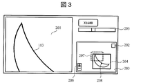
- FIG. 2 and 3 are examples of the operation screen displayed on the display unit 112.
- FIG. The display processing unit 117 of the control and calculation unit 111 displays an operation screen on the display unit 112.
- an image obtained by irradiating the sample 103 with a charged particle beam is referred to as an “observation image”
- an image for specifying an observation position on the sample 103 is referred to as an “observation position display image”.
- the operation screen includes an observation image display unit 201, an observation image capturing unit 202, an observation position display unit 203, an observation magnification setting unit 205, and an observation position display unit magnification setting unit 206.
- the observation image display unit 201 is an area for displaying an observation image. An observation image obtained by irradiating the sample 103 with a charged particle beam is input to the control and calculation unit 111 via the imaging device 110.
- the display processing unit 117 displays the observation image on the observation image display unit 201.
- the image displayed on the observation image display unit 201 is a low-magnification image obtained by capturing the entire sample 103.
- the observation position display unit 203 is an area for displaying an observation position display image.
- the observation image capturing unit 202 is an interface for capturing an observation position display image into the observation position display unit 203.
- the user clicks on the observation image capturing unit 202 using the input unit 116.
- the display processing unit 117 acquires the image displayed on the observation image display unit 201 and displays the image on the observation position display unit 203.
- the observation position display image displayed on the observation position display unit 203 is the first image 204 with a low magnification.
- the observation magnification setting unit 205 is a slide bar that can set the magnification of the observation image.
- the observation magnification setting unit 205 can increase or decrease the magnification of the observation image.
- FIG. 3 shows an example in which, after displaying the first image 204 on the observation position display unit 203, the user operates the observation magnification setting unit 205 using the input unit 116 to increase the magnification of the observation image.
- the display processing unit 117 displays an observation position indicator 207 on the observation position display unit 203 to assist in specifying the observation position.
- the position of the image currently displayed on the observation image display unit 201 is indicated on the first image 204 by the observation position indicator 207.
- the observation position indicator 207 is a frame indicating the same region as the observation field.
- the observation position display unit magnification setting unit 206 is an interface for adjusting the magnification of the observation position display unit 203, and can be used to enlarge and reduce the observation position display image.
- the first image 204 can be enlarged or reduced by the observation position display unit magnification setting unit 206.
- the magnification of the observation image is increased, the indicator indicating the observation position becomes smaller on the low-magnification image, and thus it is difficult to grasp the observation visual field range and the observation position.
- the observation position display image is enlarged by pressing the button (plus button) of the observation position display unit magnification setting unit 206. be able to.
- the image displayed on the observation position display unit 203 is enlarged, and the observation position indicator 207 indicating the observation visual field region is enlarged. Thereby, the user can grasp
- observation position indicator 207 may be a frame indicating the same area as the observation visual field or a cross cursor.
- the observation position indicator 207 only needs to be able to specify the observation position, and may have another shape.
- the observation position indicator 207 is displayed on the observation position display unit 203, but it may not be displayed.
- the display processing unit 117 displays the first image 204 on the observation position display unit 203 so that the center position of the observation image display unit 201 matches the center position of the observation position display unit 203. Therefore, when the observation position is changed by controlling the stage 105 or the deflector 108 for changing the observation position, the display processing unit 117 displays the first image 204 in the observation position display unit 203 in conjunction with the change of the observation position. Move with. In this example, the display processing unit 117 always displays the current observation position (observation position indicator 207) at the center position of the observation position display unit 203. As another example, the observation position indicator 207 may be moved in the observation position display unit 203 in conjunction with the control of the stage 105 or the deflector 108 without moving the first image 204.
- the setting processing unit 118 receives information about the click on the observation position display unit 203, the setting processing unit 118 transmits a control signal to the stage control device 120 or the deflection control device 130. Thereby, the observation position corresponding to the clicked position is moved.
- the display processing unit 117 displays the observation image at the observation position after movement on the observation image display unit 201 and moves the first image 204 so that the clicked position becomes the center of the observation position display unit 203.
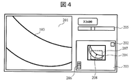
- FIG. 4 shows the operation screen after the observation position is designated. The user clicks a position 208 on the operation screen of FIG.
- the setting processing unit 118 transmits a control signal to the stage control device 120 or the deflection control device 130 so that the position 208 becomes the observation position.
- the display processing unit 117 displays the observation image at the observation position on the observation image display unit 201, and moves the first image 204 so that the clicked position 208 becomes the center of the observation position display unit 203.
- the above designation method can be various as long as the observation position can be designated.
- the observation position designation method may be a click method or a method of moving the first image 204 with respect to the observation position indicator 207 by drag and drop. Further, when using a touch panel, the above designation method may be a touch operation, a drag operation, or the like.
- the designation of the observation position may be performed on the observation image display unit 201.
- the user clicks an arbitrary position on the observation image display unit 201.
- the setting processing unit 118 transmits a control signal to the stage control device 120 or the deflection control device 130 so that the clicked position becomes the observation position (that is, the clicked position becomes the center position of the observation image display unit 201).
- the display processing unit 117 displays the observation image at the observation position on the observation image display unit 201, and moves the first image 204 so that the clicked position becomes the center of the observation position display unit 203.
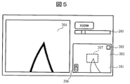
- FIG. 5 and 6 show an embodiment in which a plurality of images are taken into the observation position display unit 203.
- FIG. In this embodiment, a plurality of images with different magnifications can be taken into the observation position display unit 203.
- the user clicks the observation image capturing unit 202 using the input unit 116.
- the display processing unit 117 displays the second image 301 having an observation magnification higher than that of the first image 204 on the observation position display unit 203.
- the second image 301 has a narrower field of view than the first image 204, but is an image with higher resolution and more information when compared in the same field of view.
- a high-magnification image can be acquired in an area in which the user is interested, and the image can be captured as an observation position display image. Therefore, it is possible to create an observation position display map having a larger amount of information in an area in which the user is interested.
- the first image 204 and the second image 301 captured by the observation image capturing unit 202 are stored in the main storage device 114 or the secondary storage device 115 in a format associated with the coordinate position of each image.
- the display processing unit 117 based on the magnification and coordinates when the observation images (here, the first image 204 and the second image 301) are acquired, a plurality of observation position display images (the first image 204 and the second image 301).
- the second image 301) is displayed on the observation position display unit 203 in an overlapping manner.
- FIG. 5 shows an example in which the user operates the observation magnification setting unit 205 using the input unit 116 after taking the second image 301 into the observation position display unit 203, and further increases the magnification of the observation image.
- the position of the observation image currently displayed on the observation image display unit 201 is indicated on the second image 301 by the observation position indicator 207.
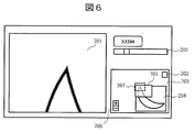
- FIG. 6 shows an example in which the observation position display images (first image 204 and second image 301) are reduced by pressing the button (minus button) of the observation position display unit magnification setting unit 206.
- the first image 204 and the second image 301 are displayed at a position corresponding to the coordinate position based on the coordinate position at the time of shooting.
- the first image 204 and the second image 301 are displayed superimposed on the observation position display unit 203. Since the second image 301 is a high-magnification image, the display size of the second image 301 in the observation position display unit 203 is smaller than the display size of the first image 204.
- the display processing unit 117 displays the second image 301 whose size has been adjusted in an overlapping manner at a corresponding position (coordinate position) in the first image 204.
- 5 and 6 show an example in which two images having different magnifications at the time of observation are captured in the observation position display unit 203. Of course, three or more images are captured in the observation position display unit 203. Also good.
- the user can capture a plurality of images with different magnifications as observation position display images into the observation position display unit 203 while appropriately changing the magnification and the observation position of the observation image.
- the magnification of the observation image is low, the observation position can be specified by the low magnification image (first image 204).
- the magnification of the observation image is high, the high magnification image (second image 301).
- the observation position can be specified with.
- the user in the region near the structure to be observed, the user can capture many high-resolution images, and as a result, information increases.
- the user in a region where only the appearance of the sample 103 needs to be known, it is only necessary to capture one low-resolution image. Therefore, the user can create a map for specifying the observation position while appropriately changing the magnification and the observation position of the observation image according to the user's own observation target at that time.
- the amount of image memory used can be reduced. Further, since the irradiation amount of the charged particle beam to the sample 103 is also reduced, damage to the sample 103 can be reduced.
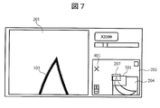
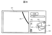
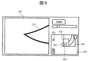
- FIG. 7 to FIG. 9 show an embodiment in the case of using the rotation operation by the stage and the optical system.
- the stage 105 includes two axes (X axis and Y axis) that move perpendicularly to the charged particle beam and an axis (Z axis) that moves the sample 103 in a direction (vertical direction) parallel to the charged particle beam.
- the stage 105 includes an axis (T axis) that tilts the sample 103 around an axis orthogonal to the charged particle beam, and an axis (R axis) that rotates the sample 103 around an axis parallel to the charged particle beam. ).
- T axis that tilts the sample 103 around an axis orthogonal to the charged particle beam
- R axis axis
- FIG. 7 shows an operation screen before the rotation operation by the stage or the optical system.
- FIG. 8 shows an operation screen when a rotation operation is performed by the R-axis stage.
- the optical system 102 includes a mechanism that changes the scanning direction of the charged particle beam. Therefore, the optical system 102 can change the scanning direction of the charged particle beam and rotate and display the observation image.
- FIG. 9 shows an operation screen when the rotation operation is performed by the deflector 108 of the optical system 102.
- the display processing unit 117 rotates the first image 204 and the second image 301 around the center (reference numeral 402) of the observation position display unit 203 in conjunction with the rotation.
- the display processing unit 117 displays the first image 204 and the second image 301 in conjunction with this. Move.
- the orientation of the image (first image 204 and second image 301) on the observation position display unit 203 always matches the observation image on the observation image display unit 201. Therefore, the user can intuitively grasp the direction of the sample 103, and the operability is improved.
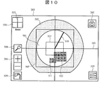
- FIG. 10 is an example of the observation position display unit 203. 10, the same components as those in FIGS. 2 and 3 are denoted by the same reference numerals and description thereof is omitted.
- the positional relationship between the sample 103 and the sample stage 104 is unknown. If the observation position display image is not taken into the observation position display unit 203, the position of the sample 103 in the sample chamber 101 is unknown. Therefore, the observation position display unit 203 displays the sample table simulation diagram 501 and the sample chamber cross-section simulation diagram 502. This makes it possible to roughly grasp the position of the sample 103 in the sample chamber 101 and the positional relationship between the sample stage 104 and the observation sample before taking the observation position display image into the observation position display unit 203. Become.
- the display processing unit 117 changes the size of the sample table simulation diagram 501 in conjunction with the size of the sample table 104 and displays it on the observation position display unit 203. Therefore, the positional relationship of the sample 103 in the sample chamber 101 can be grasped more intuitively.
- the display processing unit 117 moves the sample stage simulation diagram 501 on the observation position display unit 203 in conjunction with the movement of the stage 105.
- the user can grasp
- the stage 105 may be moved to the clicked position by clicking an arbitrary position on the observation position display unit 203.
- the setting processing unit 118 receives information about the click on the observation position display unit 203, the setting processing unit 118 transmits a control signal to the stage control device 120.
- the sample stage simulation diagram 501 of the observation position display unit 203 may be moved by drag and drop, and thereby the stage 105 may be moved.
- the setting processing unit 118 transmits a control signal to the stage control device 120 so that the position of the sample stage simulation diagram 501 after the drag and drop matches the position of the stage 105.
- the observation visual field can be changed by clicking or dragging and dropping in the observation position display unit 203.
- it is advantageous that the observation position can be designated by drag and drop.
- the display processing unit 117 displays a center indicator 503 indicating the currently observed position on the observation position display unit 203.
- the user can specify an accurate observation position with the center indicator 503.
- the display processing unit 117 controls to reduce the size of the observation position indicator 207 when the magnification of the observation image increases. Further, the display processing unit 117 performs control so that the size of the observation position indicator 207 is increased when the magnification of the observation image is decreased.
- the display processing unit 117 controls to increase the size of the observation position indicator 207. Further, when the magnification of the observation position display unit 203 is lowered by the observation position display unit magnification setting unit 206, the display processing unit 117 controls to reduce the size of the observation position indicator 207. According to the above control, it is possible to accurately grasp the visual field range of the current observation position.
- the display processing unit 117 displays the captured observation position display image over the entire observation position display unit 203.
- the magnification of the observation position display unit 203 is adjusted. As a result, the current observation magnification and the magnification of the observation position display unit 203 can be matched immediately after image capture. With this function, the user can accurately grasp the observation position without operating the magnification of the observation position display unit 203. Further, by adjusting the magnification of the observation position display unit 203, the user can immediately grasp which position on the sample 103 is observed.
- the display processing unit 117 may display a square frame having the same size as the image.
- a mark such as a dot or a circle may be displayed at the position of the image.
- the display processing unit 117 may hide the image when the observation position display image is smaller than a predetermined size.
- a first image 511 and a second image 512 are displayed on the observation position display unit 203.
- the first image 511 is a high-magnification image when observed at a high magnification
- the second image 512 is a low-magnification image when observed at a magnification lower than that of the first image 511.
- the display processing unit 117 hides the first image 511 when the first image 511 is smaller than a predetermined size.
- the display processing unit 117 displays the first image 511 again.
- the observation image capturing unit 202 may be a button as shown in FIG. 10 or may be realized in another format.
- the observation image capturing unit 202 may be realized by another interface such as a mouse gesture or a gesture by a touch monitor function.
- the display processing unit 117 displays the observation image as an observation position display image in the observation position display unit 203. You may capture it.
- an observation image may be automatically taken into the observation position display unit 203 as an observation position display image under observation conditions designated in advance by the user.
- the display processing unit 117 may manage the history captured by the observation image capturing unit 202.
- the display processing unit 117 may manage the history of the coordinates at which the observation position display image is captured, and display the history on the operation screen.
- the user can designate coordinates from which the observation position display image has been captured in the past.
- the setting processing unit 118 controls to move the observation position to the designated coordinates. Thereby, the position where the observation position display image is taken in can be reproduced, and the observation position display image can be easily re-captured.
- the display processing unit 117 performs calculation so that the magnifications of the first image 511 and the second image 512 coincide with each other, and displays the calculated first image 511 and second image 512 on the observation position display unit 203. Therefore, as shown in FIG. 10, the first image 511 is an image taken at a higher magnification than the second image 512. Therefore, the display size of the first image 511 in the observation position display unit 203 is the second image. The display size is smaller than 512.
- the observation image capturing unit 202 has a function of storing an observation image at an arbitrary position as an observation position display image, but is not limited thereto.
- the control and calculation unit 111 may acquire the observation position display image by repeating stage control and image storage so as to acquire an observation image of the entire area of the sample stage 104.
- the observation position display unit 203 includes a continuous image capturing unit 504. The user clicks the continuous image capturing unit 504 using the input unit 116.
- the setting processing unit 118 controls the stage 105 or the deflector 108 to photograph the entire area of the sample stage 104.
- the display processing unit 117 arranges the plurality of captured images on the observation position display unit 203 according to the coordinates of those positions. Thereby, for example, a low-magnification wide-area image can be automatically acquired.
- the user can specify an area of interest while viewing the wide area image, capture a high-magnification image of the area into the observation position display unit 203, and create a map in which the high-magnification image is superimposed on the low-magnification wide area image. it can.
- the continuous image capturing may be performed continuously at a preset magnification, or an image of the entire area of the sample may be captured at the magnification currently observed.
- the observation position display unit 203 includes a deflection amount display indicator 505 and a deflection cancellation function 506.
- FIG. 11 is a diagram for explaining the operation of the deflection amount display indicator 505.
- the display processing unit 117 moves the vertical axis and the horizontal axis of the deflection amount display indicator 505 according to the deflection amount. Thereby, it can be shown to the user how much the stage position and the observation position are deviated at the time of observation.
- the shape of the deflection amount display indicator 505 does not have to be a cross, and may be another shape such as a circle or a point.
- the deflection amount display indicator 505 may be any indicator that can know the direction and size from the reference position.
- the deflection cancellation function 506 functions both as a frame for displaying the deflection amount display indicator 505 and as a button for canceling the deflection of the charged particle beam.
- the setting processing unit 118 transmits a control signal to the deflection control device 130 so as to cancel the deflection. Thereby, it is possible to reduce the displacement of the captured image by eliminating the deflection amount and matching the stage coordinate position and the observation position.
- the observation position display image is arranged in the observation position display unit 203 based only on the stage coordinates, but the present invention is not limited to this.
- the control and calculation unit 111 may capture the observation position display image into the observation position display unit 203 in a coordinate system that also considers the deflection amount. In the case of this configuration, the above-described function relating to deflection may not be provided.
- the observation position display unit 203 includes a movable range frame 507.
- a movable range frame 507 represents the movable limit of the stage 105 in this example.
- a method of displaying a message that is outside the movable range when the outside of the movable range of the stage is designated as the movement destination is well known.
- the display processing unit 117 performs control so that the sample stage simulation diagram 501 can move only within the movable range frame 507. Thereby, unnecessary operations and display of error messages can be omitted, and the user's trouble can be reduced.
- the display processing unit 117 may display a warning message on the operation screen at the time of dropping without applying the above restriction.
- the magnification of the observation position display unit 203 can be changed using the observation position display unit magnification setting unit 206.
- the observation position display image is enlarged by the observation position display unit magnification setting unit 206.
- the display size of the observation position indicator 207 also increases.
- the magnification change of the observation position display unit 203 is not limited to the configuration of the observation position display unit magnification setting unit 206.
- the magnification change of the observation position display unit 203 may be performed via another interface such as a mouse wheel, a mouse gesture, or a gesture based on a touch monitor function.
- the observation position display unit 203 includes a coordinate registration unit 508.
- the user clicks the coordinate registration unit 508 using the input unit 116.
- the display processing unit 117 associates the observation image with the coordinates of the observation position and stores them in the main storage device 114 or the secondary storage device 115.
- the registered coordinates are the coordinates of the center of the observation field.
- the display processing unit 117 may display a registered position mark on the observation position display unit 203. In this case, the display processing unit 117 moves the observation position display image and the mark while maintaining the positional relationship when the observation position is moved.
- the set of the observation image and the coordinates of the observation position may be recorded in the main storage device 114 or the secondary storage device 115 in association with a predetermined identifier.
- the operation screen may display a window for designating the coordinates of the observation position. In this case, when the user designates the identifier of the coordinates, the operation screen moves to the observation position corresponding to the identifier. As another example, when a mark on the observation position display unit 203 is clicked, the observation visual field may be moved to a coordinate position corresponding to the mark.
- the magnification of the observation position display unit 203 When the magnification of the observation position display unit 203 is set to a high magnification, the magnification of the observation position display unit 203 may be set to a low magnification in order to grasp which part of the entire sample 103 is being viewed. In this case, in order to reduce the magnification to such an extent that the entire sample 103 is displayed on the observation position display unit 203, it is necessary to click the observation position display unit magnification setting unit 206 several times. This operation is troublesome for the user. Therefore, in the example of FIG. 10, the observation position display unit 203 includes a magnification changing unit 509 for changing to a specified magnification. The user clicks the magnification changing unit 509 using the input unit 116.
- the display processing unit 117 When the display processing unit 117 receives the input, the display processing unit 117 switches to the specified magnification specified in advance by the user. For example, a magnification at which the entire sample is displayed is set in advance as a specified magnification. Accordingly, it is possible to immediately confirm which part of the sample 103 is being observed at the time of observation by simply clicking the magnification changing unit 509 once. Therefore, usability is improved.
- the observation position display unit 203 may have a function of setting the specified magnification of the magnification changing unit 509 while the user confirms the observation position display unit 203. For example, when the user enlarges or reduces the observation position display unit 203 by using the observation position display unit magnification setting unit 206 and reaches a desired magnification, the user can use the arbitrary designation method (for example, setting by right click) It may be configured such that the magnification can be designated as the specified magnification of the magnification changing unit 509.
- the observation position display unit 203 includes a stage rotation angle indicator 510.
- a stage rotation angle indicator 510 represents a rotation angle when the R-axis stage is rotated and the direction of the sample 103 is rotated.
- the display processing unit 117 rotates the stage rotation angle indicator 510 about the center of the observation position display unit 203 as an axis in accordance with the rotation of the R axis stage. Thereby, the user can easily grasp the rotation angle of the R-axis stage.
- the first image 511 and the second image 512 may overlap.
- the anteroposterior relationship between the first image 511 and the second image 512 may be switched according to necessary information.
- the high-magnification first image 511 is displayed before the low-magnification second image 512.
- an image with more information is displayed on the front surface. Therefore, each time an image is taken into the observation position display unit 203, the observation position is changed.
- the amount of information for specifying increases. You may change the context of this image according to conditions. For example, in the case of the sample 103 that changes with time, the display processing unit 117 may display an image with a new shooting time on the front surface. Thereby, the observation position can be specified by an image close to the current state of the sample 103 being observed.
- the display processing unit 117 may control the order of the plurality of images according to the observation conditions of the charged particle beam device such as the degree of vacuum, the acceleration voltage, and the beam diameter on the sample. For example, when the degree of vacuum is low, an electron beam is generally scattered, resulting in an image with poor visibility.
- the display processing unit 117 acquires information on the degree of vacuum as an observation condition.
- the display processing unit 117 may display an image captured when the degree of vacuum is high in the observation position display unit 203 in front of the image captured when the degree of vacuum is low.
- the display processing unit 117 may preferentially display an image captured when the acceleration voltage is high in the observation position display unit 203 on the front surface. In this case, the user can preferentially view an image with high resolution.
- the display processing unit 117 may preferentially display an image captured when the acceleration voltage is low in the observation position display unit 203 on the front surface. In this case, the user can preferentially view the information on the sample surface.
- the display processing unit 117 preferentially displays the image captured when the beam diameter on the sample is small on the front surface in the observation position display unit 203. May be.
- the display processing unit 117 may preferentially display the image captured when the on-sample beam diameter is large in the observation position display unit 203 on the front surface.
- the charged particle beam apparatus may include a plurality of detectors.
- an observation image is acquired while switching a plurality of detectors. Since the observation position display image is not limited to a specific detector signal, images acquired by a plurality of types of detectors may be arranged on the observation position display unit 203 at the same time. If the type of detector is different, the appearance of the same sample may vary greatly. In this case, the observation position display image may not correspond to the observation image.
- the display processing unit 117 may preferentially display the image acquired by the currently selected detector in the observation position display unit 203 on the front surface. As a result, the observation image and the image of the observation position display unit 203 look the same, and the observation position can be accurately displayed.
- the above-described context control of the image may be automatically switched by the control and calculation unit 111 according to the observation target and purpose of the apparatus, or may be selected by the user.
- the display method of the image in the observation position display unit 203 is not limited to simple superimposition of images.
- the display processing unit 117 may transmit a front image among a plurality of images. According to this method, the user can also view information on the rear image, and can present more information to the user.
- the display processing unit 117 may artificially color a plurality of images. For example, in the case of an image of a signal from which composition information is obtained, the display processing unit 117 may artificially color the image according to the composition in the observation position display unit 203 and superimpose these images. Thereby, the user can grasp not only the shape information but also the difference in composition at a glance, and can present more information to the user.
- the display processing unit 117 may add pseudo-different colors to images obtained from signals from different detectors.
- the display processing unit 117 may superimpose and display these images.
- the display processing unit 117 may generate an image in which only the edge portion is extracted, and the observation position display unit 203 may superimpose a plurality of edge-enhanced images. Good. Thereby, the visibility in an image improves.
- an image taken by a charged particle beam apparatus is described.
- an image used for displaying an observation position is not limited to a charged particle beam apparatus, but is a camera, an optical microscope, a fluorescence microscope, a laser microscope, an X-ray image. As long as it is an image of an observation sample. Further, as the observation position display, not only a photographed image but also a design drawing such as a CAD diagram may be used.
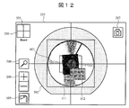
- FIG. 12 shows an example in which an image taken by the optical camera is displayed on the observation position display unit 203.
- an optical camera 143 is mounted on the upper part of the sample chamber 101 (see FIG. 1).
- the display processing unit 117 acquires the optical image 601 captured by the optical camera 143, and displays the optical image 601 on the observation position display unit 203.
- the image displayed on the observation position display unit 203 is not limited to the image captured by the camera, and may be an image related to the sample 103.
- the display processing unit 117 may display an image of a signal of a different type from the signal used for observation or a diagram representing the shape of the sample on the observation position display unit 203 simultaneously with or while switching to other images.
- the display processing unit 117 trims the optical image 601 in accordance with the shape of the sample stage 104 and displays the optical image 601 on the observation position display unit 203. According to this configuration, unnecessary information outside the outer shape of the sample stage 104 can be deleted, and the observation position can be presented to the user in a state closer to the real object.
- the optical image 601 may be overlaid on the sample stage simulation diagram 501 of FIG. As another example, the sample stage simulation diagram 501 may be replaced by the optical image 601.
- the user can grasp rough information of the entire sample before observation by the charged particle beam apparatus.
- the user can specify an area of interest while viewing the optical image 601 of the entire sample, and can take an observation image of the area into the observation position display unit 203. Thereby, a map in which the observation image is superimposed on the optical image 601 can be created.
- the display processing unit 117 may convert the color image into a grayscale image when the magnification of the observation position display unit 203 exceeds a certain threshold value. Thereby, enlarged display is possible without impairing visibility.
- the operation screen includes a magnification interlocking function execution unit 701.
- the magnification interlocking function execution unit 701 is used to match the magnification of the observation image on the observation image display unit 201 with the magnification of the observation position display unit 203.
- the user clicks the magnification interlocking function execution unit 701 using the input unit 116.
- the setting processing unit 118 controls the components of the charged particle beam apparatus so that the magnification of the observation image matches the magnification of the observation position display unit 203.
- the display processing unit 117 displays the observation image after the magnification correction on the observation image display unit 201 (FIG. 14). According to this function, it is possible to reduce sample damage when searching for an observation position. Further, after determining a rough observation position in the state of FIG. 14, the user can designate a detailed observation position as shown in FIG.
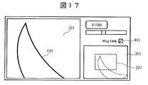
- FIG. 16 and 17 show a second example in which the magnification of the observation image and the magnification of the observation position display unit 203 are controlled in conjunction with each other.
- FIG. 17 shows a state where the magnification of the observation image is increased from the state of FIG.
- the display processing unit 117 controls the magnification of the observation image and the magnification of the observation position display unit 203 to be relatively constant.
- the observation position indicator 207 is displayed with a constant display size.
- the display processing unit 117 displays the observation position display image in a state where the magnification of the observation position display unit 203 is slightly lower than the magnification of the observation image of the observation image display unit 201.
- the operation screen includes a magnification link function execution unit 801 that can switch the above-described control between valid / invalid.
- the magnification link function execution unit 801 can switch the above-described control between valid / invalid, but the above-described control may be always valid.
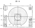
- FIG. 18 shows an observation position display unit 203 obtained by further expanding the configuration of FIG.
- the observation position display unit 203 includes an observation image non-display function 901 and a Z-direction image switching function 902.
- the observation image non-display function 901 is a function for switching between valid / invalid of charged particle beam irradiation on the sample 103.
- the user clicks the magnification link function execution unit 701 using the input unit 116.
- the setting processing unit 118 controls irradiation of the charged particle beam. For example, the voltage application to the charged particle source (for example, electron gun) may be stopped, or the deflector 108 may be controlled so that the sample 103 is not irradiated with the charged particle beam.
- the charged particle source for example, electron gun
- the user may enable the observation image non-display function 901.
- the observation image is not displayed on the observation image display unit 201, and only the observation position display unit 203 is displayed. Thereby, it can move to an observation position, without giving unnecessary sample damage.
- This configuration is particularly effective for an apparatus using a beam having a large influence on the sample, such as a focused ion beam.
- the Z-direction image switching function 902 is a function for hierarchizing the observation position display unit 203 and switching the display for each layer.
- an observation position display image may be captured for each acceleration voltage, and a plurality of observation position display images may be hierarchized and stored in the main storage device 114 or the secondary storage device 115.
- the display processing unit 117 displays these hierarchized images for displaying the observation position according to the operation of the button of the Z-direction image switching function 902. For example, when the upper button of the Z-direction image switching function 902 is clicked, the display processing unit 117 displays the observation position display image of the next higher level. According to this configuration, it is possible to switch between information on the sample surface and information inside the sample.
- an image for displaying an observation position is acquired before processing the sample 103, and these images are stored in layers. According to this configuration, it is possible to confirm again the structure that has already disappeared on the observation position display unit 203 while processing the sample 103.
- the display processing unit 117 may switch between display and non-display of each observation position display image according to the observation conditions (acceleration voltage value, degree of vacuum, detector, etc.).
- the observation position display image may be stored in the main storage device 114 or the secondary storage device 115 in association with the observation condition.
- the observation position display unit 203 may include an input form for designating observation conditions.
- the observation position display image and coordinate information of the observation position display unit 203 described with reference to FIGS. 2 to 18 can be reproduced without using the apparatus after the observation by the charged particle beam apparatus is completed.
- the observation position display image and the coordinate information stored in the secondary storage device 115 may be referred to by a device other than the charged particle beam device. Thereby, when it is desired to perform observation again later, it is not necessary to use a charged particle beam apparatus, and it is possible to perform pseudo observation with a charged particle beam apparatus.
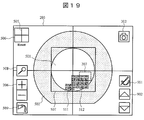
- FIG. 19 shows another configuration of the observation position indicator 207. As shown in FIG. 19, with the movement of the observation position, the display processing unit 117 may move the observation position indicator 207 to the corresponding observation position.
- the observation position indicator 207 may be displayed in another format as long as the relationship between the magnification and the coordinates of the observation image display unit 201 and the observation position display unit 203 is maintained.
- FIG. 20 is an example in which the positional relationship of a plurality of detectors is displayed on the observation position display unit 203.
- the charged particle beam apparatus includes an EDX (Energy Dispersive X-ray Spectrometry) detector, a backscattered electron detector, a secondary electron detector, and a camera.
- the observation position display unit 203 displays a first detector position display 1101, a second detector position display 1102, a third detector position display 1103, and a camera position display 1104.
- the first detector position display 1101 represents the position of the EDX detector in the sample chamber 101.
- the second detector position display 1102 represents the position of the backscattered electron detector in the sample chamber 101 and also has a function of switching the signal of the observation image.
- the third detector position display 1103 represents the position of the secondary electron detector in the sample chamber 101 and also has a function of switching the signal of the observation image.
- the camera position display 1104 represents the position of the camera for observing the inside of the sample chamber, and also has a function of switching to a camera image.
- the display processing unit 117 switches the observation image on the observation image display unit 201 to an observation image based on a signal from the backscattered electron detector.
- the display processing unit 117 switches the observation image on the observation image display unit 201 to an image from the camera. In this way, the observation image can be switched using a plurality of detectors and camera marks in the observation position display unit 203.
- the display processing unit 117 may display the currently selected detector and the unselected detector in different display formats. For example, the display processing unit 117 may display the currently selected detector and the unselected detector in different colors. Thereby, the user can grasp
- the image from the sample room observation camera may be displayed on the observation image display unit 201 or may be displayed on the observation position display unit 203 as an auxiliary function.
- the display processing unit 117 may display a message when a plurality of detectors and camera marks in the observation position display unit 203 are clicked according to the observation conditions. For example, some detectors cannot be used depending on conditions. For example, a secondary electron detector in an electron microscope cannot be used at low vacuum.
- the display processing unit 117 displays the status display unit 1105. In the status display section 1105, a message such as “Cannot be used at low vacuum” is displayed. Thereby, when the user tries to select a detector, the reason why the detector cannot be used can be presented. Even users who are not familiar with the device can easily understand the state of the device.
- the display processing unit 117 may display the currently selectable detector and the detector that is not currently selectable depending on the observation conditions in different display formats.
- the display processing unit 117 may display a currently selectable detector and a detector that is not currently selectable depending on observation conditions in different colors.
- the first detector position display 1101, the second detector position display 1102, the third detector position display 1103, and the camera position display 1104 are controlled so as to always maintain the relationship with the observation position display unit 203. .
- the display processing unit 117 rotates the first image 511 and the second image 512 and the stage rotation angle indicator 510, but does not rotate the position displays 1101 to 1104.
- the observation image can be rotated by controlling the scanning direction.
- the display processing unit 117 rotates all of the first image 511 and the second image 512, the stage rotation angle indicator 510, and the respective position displays 1101 to 1104 according to the control in the scanning direction.
- the charged particle beam apparatus having the observation assist function of the above-described embodiment is equipped with the optical system 102 for irradiating the observation sample with the charged particle beam generated from the charged particle source and the sample 103.
- An imaging device 110 that converts the acquired signal into an image, and a plurality of observation position display images with different magnifications are displayed on an observation position display unit 203 that can be enlarged and reduced based on the device coordinate system at the time of shooting. indicate.
- the observation position display unit 203 As a result, it is possible to display a low-magnification image and a high-magnification image on the observation position display unit 203. Further, the observation position can be confirmed by enlarging and reducing the observation position display unit 203. Thereby, even if the magnification currently observed (magnification of the observation image) and the magnification of the image displaying the observation position are greatly different, the observation position can be presented. It is possible to present it to the user regardless of.
- the charged particle beam is irradiated on the sample for each region, which causes a problem of increasing damage to the sample. There arises a problem that throughput is lowered in order to capture a plurality of necessary images.
- the throughput in observation is improved.
- the above embodiment has the following additional features.
- the display processing unit 117 may move the display position of the observation position display image in the observation position display unit 203 in conjunction with the movement by the stage 105 or the movement of the irradiation position of the charged particle beam by the deflector 108. Thereby, the user can confirm the change of the irradiation position on the observation position display unit 203 in real time.
- the observation position display unit 203 can accept a visual field movement designation by the user.
- the setting processing unit 118 controls the stage 105 or the deflector 108 to move to the designated visual field. Thereby, the observation visual field can be changed on the observation position display unit 203, and the operability is improved.
- the stage 105 has an R axis stage.
- the display processing unit 117 rotates the observation position display image with reference to the rotation center position of the R axis stage in the observation position display unit 203. Accordingly, the observation position display image is rotated in the same manner as the actual observation image, and the user can easily specify the observation position on the observation position display unit 203.
- the optical system 102 has a function of changing the charged particle beam scanning direction and rotating the image.
- the display processing unit 117 rotates the observation position display image of the observation position display unit 203 around the observation position. Accordingly, the observation position display image is rotated in the same manner as the actual observation image, and the user can easily specify the observation position on the observation position display unit 203.
- the display processing unit 117 displays a sample table simulation diagram 501 simulating the sample table 104 on the observation position display unit 203.
- the display processing unit 117 causes the observation position display unit 203 to display the observation position display image superimposed on the sample stage simulation diagram 501. Thereby, the user can intuitively grasp the inside of the sample chamber 101.
- the display processing unit 117 displays a sample chamber cross-section simulation diagram 502 simulating the sample chamber cross-section on the observation position display unit 203.
- the display processing unit 117 superimposes and displays the sample table simulation diagram 501, the sample chamber cross-section simulation diagram 502, and the observation position display image. Thereby, the position and direction of the sample in the sample chamber 101 can be intuitively presented to the user.
- the display processing unit 117 displays an observation position indicator 207 indicating the observation position on the observation position display unit 203.
- the observation position indicator 207 is enlarged / reduced according to the observation magnification of the apparatus and the magnification of the observation position display unit 203. Thereby, the user can confirm the observation visual field with a desired size.
- the observation position display unit 203 includes an observation image capturing unit 202 that allows the user to arbitrarily save an observation image. Therefore, the user can store the minimum number of images for viewing position display required. In particular, conventionally, it is a process of acquiring one low-magnification image in advance or automatically acquiring a plurality of low-magnification images as an observation position display image. Can not get. On the other hand, in this embodiment, the user acquires an observation position display image at a desired magnification and position, and an observation position display map having a larger amount of information for an area of interest to the user himself. Can be created.
- the observation position display unit 203 includes a continuous image capturing unit 504.
- the setting processing unit 118 controls the stage 105 or the deflector 108 and continuously images the entire area of the sample stage 104.
- the display processing unit 117 arranges the plurality of captured images on the observation position display unit 203 according to the coordinates of those positions. Thereby, when the user wants to acquire the entire image of the sample stage 104 as the observation position display image, these images can be acquired automatically, and the user's trouble can be reduced.
- the charged particle beam apparatus includes an imaging system other than the charged particle beam imaging system used for observation.
- the optical camera 143 is used as the imaging system, but other imaging systems may be used.
- the display processing unit 117 displays an image of a signal of a different type from the signal used for observation or a diagram representing the shape of the sample simultaneously with or switched to other images.
- the display processing unit 117 may delete and display unnecessary information outside the outer shape of the sample stage 104 regarding an image captured by an imaging system other than the charged particle beam imaging system.
- the display processing unit 117 may cut out a part of the sample stage 104 and display it on the observation position display unit 203 with respect to an image captured by an imaging system other than the charged particle beam imaging system.
- the display processing unit 117 displays an image captured by an imaging system other than the charged particle beam imaging system in an overlapping manner with the sample stage simulation diagram 501, or is captured by an imaging system other than the charged particle beam imaging system.
- the sample stage simulation diagram 501 may be replaced by the image and displayed.
- the display processing unit 117 may change an image photographed by an imaging system other than the sample stage simulation diagram 501 or the charged particle beam imaging system according to the size of the sample stage 104 under observation. Further, the display processing unit 117 may change the reference size of the image in the observation position display unit 203 according to the size of the sample stage 104 being observed.
- the display processing unit 117 displays an indicator of the deflection amount for visual field movement during the observation (deflection amount display indicator 505) in the observation position display unit 203. Thereby, the user can always grasp the difference from the stage coordinates.
- the setting processing unit 118 cancels the deflection by the deflector 108 and makes the stage coordinates coincide with the observation position.
- the display processing unit 117 may switch the color image to gray scale display according to the enlargement ratio of the observation position display unit 203.
- the observation position display unit 203 has a function of specifying an observation position by clicking.
- the display processing unit 117 displays a frame (movable range frame 507) indicating the stage movable range.
- the display processing unit 117 may display a warning message notifying that the stage is out of range when the outside of the stage movable range frame is clicked. Thereby, the user can grasp the range in which the observation position can be designated when the observation position is designated on the observation position display unit 203.
- observation position display unit 203 has a function of specifying the observation position by drag and drop.
- the display processing unit 117 restricts the center position of the observation position display unit 203 from moving outside the movable range frame 507.
- the observation position display unit 203 includes a coordinate registration unit 508 as a coordinate registration function.
- the display processing unit 117 may store the coordinates of the observation position and cause the observation position display unit 203 to display a mark indicating the registration position.
- the display processing unit 117 moves the mark together with the observation position display image as the observation position is moved.
- the display processing unit 117 displays the captured observation position display image over the entire observation position display unit 203.
- the magnification of the observation position display unit 203 is changed.
- the observation position display unit 203 includes a magnification change unit 509 that immediately sets the magnification of the observation position display unit 203 to a predetermined value.
- the observation position display unit 203 may have a function for the user to set and specify the previously specified magnification while confirming the observation position display unit 203.
- the display processing unit 117 may change the order of the plurality of observation position display images displayed in an overlapping manner in the observation position display unit 203 in accordance with a user designation or an observation condition. For example, the display processing unit 117 may display an observation position display image with a high magnification at the time of observation among a plurality of observation position display images. For example, the display processing unit 117 may display an observation position display image captured later from among a plurality of observation position display images. For example, the display processing unit 117 may display an observation position display image selected by a user interface device such as a mouse, a keyboard, or a touch panel. The display processing unit 117 may display an image obtained by a specific detection signal among a plurality of observation position display images.
- the display processing unit 117 may switch the front-rear relationship of the plurality of observation position display images according to the degree of vacuum at the time of observation.
- the display processing unit 117 may switch the relationship between the plurality of observation position display images according to the acceleration voltage at the time of observation.
- the display processing unit 117 may pseudo-color each of images obtained from signals from different detectors and display the images in a superimposed manner.
- the observation position display unit 203 has a function of displaying a plurality of observation position display images in a hierarchical manner.
- the display processing unit 117 displays an observation position display image for each layer.
- the display processing unit 117 may switch between displaying and hiding each image according to the observation conditions (acceleration voltage value, degree of vacuum, detector, etc.) associated with the observation position display image.
- the display processing unit 117 may transmit at least one image among the plurality of observation position display images in the observation position display unit 203 and superimpose it with another image.
- the display processing unit 117 may display an observation position display image captured at a high magnification with a frame.
- the display processing unit 117 may manage the coordinates at which the observation position display image is taken in as a history.
- the observation position display unit 203 has a function of designating coordinates from the history. As a result, the position where the observation position display image is captured can be reproduced, and the observation position display image can be easily re-captured.
- the observation position display image and the coordinate information of the observation position display unit 203 may be configured to be referable from another apparatus after the observation by the charged particle beam apparatus is completed.
- the observation position display image and the coordinate information may be stored in, for example, an auxiliary storage device or another storage device on the network. Thereby, the observation position display unit 203 can be reproduced without using a charged particle beam apparatus.
- the observation position display unit 203 includes a magnification interlock function execution unit 701 for making the magnification of the observation image of the observation image display unit 201 coincide with the magnification of the observation position display unit 203.
- the magnification link function execution unit 701 When the magnification link function execution unit 701 is clicked, the setting processing unit 118 sets the magnification of the observation image to the same magnification as that of the observation position display unit 203.
- the observation position display unit 203 includes an observation image non-display function 901 for switching between valid / invalid of charged particle beam irradiation on the sample.
- the setting processing unit 118 controls so that the charged particle beam does not hit the sample 103.
- the setting processing unit 118 may stop the voltage application to the charged particle source, or may control the deflector 108 so that the sample 103 is not irradiated with the charged particle beam. Thereby, sample damage can be reduced.
- the display processing unit 117 may be configured to reflect the image shift amount on the coordinates of the observation position display unit 203.
- the display processing unit 117 does not move the observation position display image but may move the marker indicating the observation position on the observation position display unit 203. Good.
- the display processing unit 117 may embed a mark in the observation position display unit 203 and display information (for example, coordinates) of the point when the mark is over the mouse.
- the observation position display unit 203 includes an interface (such as a figure or a display) that represents the positional relationship between a plurality of detectors in the sample chamber 101 and that can switch between the plurality of detectors.
- an interface such as a figure or a display
- the display processing unit 117 switches the observation image on the observation image display unit 201 to an observation image obtained by a signal from the clicked detector.
- the display processing unit 117 may display the currently selected detector and the unselected detector in different display formats. For example, the display processing unit 117 may display the currently selected detector and the unselected detector in different colors. Thereby, the user can recognize the detector selected intuitively.
- the display processing unit 117 may display the currently selectable detector and the detector that cannot be currently selected depending on the observation condition in different display formats.
- the display processing unit 117 may display a currently selectable detector and a detector that is not currently selectable depending on observation conditions in different colors. Thereby, the detector which a user cannot select intuitively can be recognized.
- the display processing unit 117 may switch display / non-display of a diagram or a display according to the positional relationship between a plurality of detectors. Thereby, when it is unnecessary, the positional relationship of the plurality of detectors can be hidden in the observation position display unit 203.
- the present invention is not limited to the above-described embodiments, and includes various modifications.
- the above embodiments have been described in detail for easy understanding of the present invention, and are not necessarily limited to those having all the configurations described.
- a part of the configuration of one embodiment can be replaced with the configuration of another embodiment.
- the structure of another Example can also be added to the structure of a certain Example.
- the operability can be improved by combining the above-described embodiments.
- another configuration can be added, deleted, or replaced.
- each of the above-described configurations, functions, processing units, processing means, and the like may be realized by hardware by designing a part or all of them with, for example, an integrated circuit.
- Each of the above-described configurations, functions, and the like may be realized by software by interpreting and executing a program that realizes each function by the processor.
- Information such as programs, tables, and files for realizing each function can be stored in various types of non-transitory computer-readable media.
- non-transitory computer-readable medium for example, a flexible disk, a CD-ROM, a DVD-ROM, a hard disk, an optical disk, a magneto-optical disk, a CD-R, a magnetic tape, a nonvolatile memory card, a ROM, and the like are used.
- control lines and information lines indicate what is considered necessary for the explanation, and not all the control lines and information lines on the product are necessarily shown. All the components may be connected to each other.
Landscapes
- Chemical & Material Sciences (AREA)
- Analytical Chemistry (AREA)
- Analysing Materials By The Use Of Radiation (AREA)
Abstract
Description
(1)低倍率の1枚の画像を提示し、前記低倍率画像上に観察位置を図示する
(2)複数枚の低倍率画像を撮影し前記低倍率画像を倍率に応じて切り替えて観察位置を図示する
(3)指定した連続した領域で画像を撮影し、画像をつなぎ合わせることで低倍率画像を作成し、試料の観察位置を図示する
図1は、荷電粒子線装置の一実施例である。荷電粒子線装置は、例えば、荷電粒子線が散乱しないように真空状態を保つ試料室101と、荷電粒子線を最終的に試料103に収束させるための光学系102と、試料103から得られる信号を検出する検出器106と、検出器106で検出された信号を画像に変換する撮像装置110とを備える。
図20は、観察位置表示部203に複数の検出器の位置関係を表示した一実施例である。この例では、荷電粒子線装置は、EDX(Energy Dispersive X-ray Spectrometry)検出器と、反射電子検出器と、二次電子検出器と、カメラとを備える。観察位置表示部203には、第1検出器位置表示1101と、第2検出器位置表示1102と、第3検出器位置表示1103と、カメラ位置表示1104とが表示される。第1検出器位置表示1101は、試料室101内におけるEDX検出器の位置を表している。第2検出器位置表示1102は、試料室101内における反射電子検出器の位置を表していると共に、観察画像の信号を切り替える機能も兼ねている。第3検出器位置表示1103は、試料室101内における二次電子検出器の位置を表していると共に、観察画像の信号を切り替える機能も兼ねている。カメラ位置表示1104は、試料室内部観察用のカメラの位置を表していると共に、カメラ映像に切り替える機能も兼ねている。
Claims (20)
- 試料台に載せられた試料に対して荷電粒子線を照射する光学系と、
前記試料から発生する信号を検出する少なくとも1つの検出器と、
前記検出した信号から観察画像を取得する撮像装置と、
前記試料における観察位置を変更するための機構であって、前記試料台を移動させるステージ及び前記荷電粒子線の照射位置を変更させる偏向器の少なくとも一方を備える機構と、
前記観察画像を表示する観察画像表示部と、前記観察画像の観察位置を表示する観察位置表示部とを有する操作画面を表示する表示部と、
前記操作画面の表示処理を制御する制御部と、
を備え、
前記制御部は、前記観察画像を取得したときの倍率及び座標に基づいて、前記倍率が異なる複数の観察位置表示用画像を前記観察位置表示部に重ねて表示することを特徴とする荷電粒子線装置。 - 請求項1に記載の荷電粒子線装置において、
前記観察位置表示部は、前記観察画像を前記観察位置表示用画像として前記観察位置表示部に取り込むための観察画像取り込み部を有し、
前記制御部は、前記観察画像取り込み部への入力を受け取ると、前記観察画像を前記観察位置表示部に取り込むことを特徴とする荷電粒子線装置。 - 請求項1に記載の荷電粒子線装置において、
前記制御部は、前記ステージ又は前記偏向器による前記観察位置の変更に応じて、前記観察位置表示部における前記観察位置表示用画像を移動又は回転させることを特徴とする荷電粒子線装置。 - 請求項1に記載の荷電粒子線装置において、
前記観察位置表示部は、前記観察位置表示部の倍率を調整するためのインターフェースを備えることを特徴とする荷電粒子線装置。 - 請求項1に記載の荷電粒子線装置において、
前記制御部は、観察位置を示す観察位置インジケーターを前記観察位置表示部に表示し、前記観察画像の倍率及び前記観察位置表示部の倍率に応じて前記観察位置インジケーターを拡大及び縮小することを特徴とする荷電粒子線装置。 - 請求項1に記載の荷電粒子線装置において、
前記制御部は、前記試料台を模擬した試料台模擬図に重ねて前記観察位置表示用画像を表示することを特徴とする荷電粒子線装置。 - 請求項1に記載の荷電粒子線装置において、
前記撮像装置以外の撮像系を更に備え、
前記制御部は、
前記撮像系で撮影された画像を前記観察位置表示部に表示し、
前記撮像系で撮影された画像に重ねて前記観察位置表示用画像を表示することを特徴とする荷電粒子線装置。 - 請求項7に記載の荷電粒子線装置において、
前記制御部は、前記観察位置表示用画像を前記観察位置表示部に表示する際に、前記試料台の外形より外側の情報を削除して表示することを特徴とする荷電粒子線装置。 - 請求項1に記載の荷電粒子線装置において、
前記制御部は、前記観察画像表示部の前記観察画像の倍率と前記観察位置表示部の倍率を連動して制御することを特徴とする荷電粒子線装置。 - 請求項1に記載の荷電粒子線装置において、
前記観察位置表示部は、複数の検出器の位置関係を表し、かつ、前記複数の検出器の切り替えが可能なインターフェースを備え、
前記制御部は、前記インターフェースを介した入力に応じて、前記観察画像表示部の前記観察画像を、選択された検出器から得られる観察画像に切り替えることを特徴とする荷電粒子線装置。 - 荷電粒子線装置を用いた観察方法であって、
光学系によって、試料台に載せられた試料に対して荷電粒子線を照射するステップと、
少なくとも1つの検出器によって、前記試料から発生する信号を検出するステップと、
撮像装置によって、前記検出した信号から観察画像を取得するステップと、
制御部によって、前記観察画像を表示する観察画像表示部と、前記観察画像の観察位置を表示する観察位置表示部とを有する操作画面を表示部に表示するステップと、
前記制御部によって、前記観察画像を取得したときの倍率及び座標に基づいて、前記倍率が異なる複数の観察位置表示用画像を前記観察位置表示部に重ねて表示するステップと、
を含む観察方法。 - 請求項11に記載の観察方法において、
前記観察位置表示部は、前記観察画像を前記観察位置表示用画像として前記観察位置表示部に取り込むための観察画像取り込み部を有し、
前記制御部によって、前記観察画像取り込み部への入力を受け取ると、前記観察画像を前記観察位置表示部に取り込むステップをさらに含むことを特徴とする観察方法。 - 請求項11に記載の観察方法において、
前記試料台を移動させるステージ及び前記荷電粒子線の照射位置を変更させる偏向器の少なくとも一方によって、前記試料における観察位置を変更するステップと、
前記制御部によって、前記ステージ又は前記偏向器による前記観察位置の変更に応じて、前記観察位置表示部における前記観察位置表示用画像を移動又は回転させるステップと、
をさらに含むことを特徴とする観察方法。 - 請求項11に記載の観察方法において、
前記制御部によって、前記観察位置表示部の倍率を調整するステップをさらに含むことを特徴とする観察方法。 - 請求項11に記載の観察方法において、
前記制御部によって、観察位置を示す観察位置インジケーターを前記観察位置表示部に表示するステップと、
前記制御部によって、前記観察画像の倍率及び前記観察位置表示部の倍率に応じて前記観察位置インジケーターを拡大及び縮小するステップと、
をさらに含むことを特徴とする観察方法。 - 請求項11に記載の観察方法において、
前記制御部によって、前記試料台を模擬した試料台模擬図に重ねて前記観察位置表示用画像を表示するステップをさらに含むことを特徴とする観察方法。 - 請求項11に記載の観察方法において、
前記撮像装置以外の撮像系によって、画像を撮影するステップと、
前記制御部によって、前記撮像系で撮影された画像を前記観察位置表示部に表示するステップと、
前記制御部によって、前記撮像系で撮影された画像に重ねて前記観察位置表示用画像を表示するステップと、
を含むことを特徴とする観察方法。 - 請求項11に記載の観察方法において、
前記制御部によって、前記観察画像表示部の前記観察画像の倍率と前記観察位置表示部の倍率を連動して制御するステップをさらに含むことを特徴とする観察方法。 - 請求項11に記載の観察方法において、
前記制御部によって、複数の検出器の位置関係を表し、かつ、前記複数の検出器の切り替えが可能なインターフェースを前記観察位置表示部に表示するステップと、
前記制御部によって、前記インターフェースを介した入力に応じて、前記観察画像表示部の前記観察画像を、選択された検出器から得られる観察画像に切り替えるステップと、
をさらに含むことを特徴とする観察方法。 - 荷電粒子線装置によって得られた観察画像を表示する処理を、演算部と記憶部と表示部とを備える情報処理装置に実行させるプログラムであって、
前記演算部に、
前記観察画像を表示する観察画像表示部と、前記観察画像の観察位置を表示する観察位置表示部とを有する操作画面を前記表示部に表示する表示処理と、
前記観察画像を取得したときの倍率及び座標に基づいて、前記倍率が異なる複数の観察位置表示用画像を前記観察位置表示部に重ねて表示する表示処理と
を実行させるためのプログラム。
Priority Applications (6)
| Application Number | Priority Date | Filing Date | Title |
|---|---|---|---|
| PCT/JP2015/082989 WO2017090100A1 (ja) | 2015-11-25 | 2015-11-25 | 荷電粒子線装置、荷電粒子線装置を用いた観察方法、及び、プログラム |
| DE112015007007.9T DE112015007007T5 (de) | 2015-11-25 | 2015-11-25 | Ladungsträgerstrahlvorrichtung, beobachtungsverfahren unter verwendung der ladungsträgerstrahlvorrichtung und programm |
| JP2017552569A JP6462150B2 (ja) | 2015-11-25 | 2015-11-25 | 荷電粒子線装置、荷電粒子線装置を用いた観察方法、及び、プログラム |
| US15/773,445 US10453650B2 (en) | 2015-11-25 | 2015-11-25 | Charged particle beam apparatus, observation method using charged particle beam apparatus, and program |
| CN201580084713.3A CN108292578B (zh) | 2015-11-25 | 2015-11-25 | 带电粒子射线装置、使用带电粒子射线装置的观察方法及程序 |
| US16/576,252 US10763074B2 (en) | 2015-11-25 | 2019-09-19 | Charged particle beam apparatus, observation method using charged particle beam apparatus, and program |
Applications Claiming Priority (1)
| Application Number | Priority Date | Filing Date | Title |
|---|---|---|---|
| PCT/JP2015/082989 WO2017090100A1 (ja) | 2015-11-25 | 2015-11-25 | 荷電粒子線装置、荷電粒子線装置を用いた観察方法、及び、プログラム |
Related Child Applications (2)
| Application Number | Title | Priority Date | Filing Date |
|---|---|---|---|
| US15/773,445 A-371-Of-International US10453650B2 (en) | 2015-11-25 | 2015-11-25 | Charged particle beam apparatus, observation method using charged particle beam apparatus, and program |
| US16/576,252 Continuation US10763074B2 (en) | 2015-11-25 | 2019-09-19 | Charged particle beam apparatus, observation method using charged particle beam apparatus, and program |
Publications (1)
| Publication Number | Publication Date |
|---|---|
| WO2017090100A1 true WO2017090100A1 (ja) | 2017-06-01 |
Family
ID=58763202
Family Applications (1)
| Application Number | Title | Priority Date | Filing Date |
|---|---|---|---|
| PCT/JP2015/082989 Ceased WO2017090100A1 (ja) | 2015-11-25 | 2015-11-25 | 荷電粒子線装置、荷電粒子線装置を用いた観察方法、及び、プログラム |
Country Status (5)
| Country | Link |
|---|---|
| US (2) | US10453650B2 (ja) |
| JP (1) | JP6462150B2 (ja) |
| CN (1) | CN108292578B (ja) |
| DE (1) | DE112015007007T5 (ja) |
| WO (1) | WO2017090100A1 (ja) |
Cited By (2)
| Publication number | Priority date | Publication date | Assignee | Title |
|---|---|---|---|---|
| WO2020188781A1 (ja) * | 2019-03-20 | 2020-09-24 | 株式会社日立ハイテク | 荷電粒子線装置 |
| WO2025009129A1 (ja) * | 2023-07-05 | 2025-01-09 | 株式会社日立ハイテク | 観察支援装置 |
Families Citing this family (1)
| Publication number | Priority date | Publication date | Assignee | Title |
|---|---|---|---|---|
| WO2020217354A1 (ja) * | 2019-04-24 | 2020-10-29 | 株式会社日立ハイテク | 荷電粒子ビーム装置、及びその作動方法 |
Citations (2)
| Publication number | Priority date | Publication date | Assignee | Title |
|---|---|---|---|---|
| JP2012099481A (ja) * | 2010-11-03 | 2012-05-24 | Carl Zeiss Smt Ltd | 顕微鏡システム、荷電粒子顕微鏡を操作する方法 |
| JP2014229587A (ja) * | 2013-05-27 | 2014-12-08 | 株式会社日立ハイテクノロジーズ | 電子顕微鏡および電子顕微鏡制御方法 |
Family Cites Families (9)
| Publication number | Priority date | Publication date | Assignee | Title |
|---|---|---|---|---|
| JP3230911B2 (ja) * | 1993-11-04 | 2001-11-19 | 株式会社日立製作所 | 走査電子顕微鏡及びその画像形成方法 |
| JPH0830319A (ja) | 1994-07-13 | 1996-02-02 | Fanuc Ltd | レーザセンサの検出角度制御方法 |
| JP3293739B2 (ja) | 1996-06-13 | 2002-06-17 | 株式会社日立製作所 | 走査電子顕微鏡 |
| JP2004158392A (ja) * | 2002-11-08 | 2004-06-03 | Keyence Corp | 電子顕微鏡、電子顕微鏡の操作方法、電子顕微鏡操作プログラムおよびコンピュータで読み取り可能な記録媒体 |
| JP4236123B1 (ja) * | 2008-04-21 | 2009-03-11 | 株式会社林創研 | 三次元画像取得装置 |
| JP5352262B2 (ja) * | 2009-02-06 | 2013-11-27 | 株式会社日立ハイテクノロジーズ | 荷電粒子線装置 |
| JP5506345B2 (ja) * | 2009-11-26 | 2014-05-28 | 株式会社日立ハイテクノロジーズ | 荷電粒子線顕微鏡および当該荷電粒子顕微鏡の制御方法 |
| DE112013001112B4 (de) * | 2012-03-16 | 2018-08-02 | Hitachi High-Technologies Corporation | Ladungsteilchenstrahlgerät und Probenobservationssystem |
| JP5464533B1 (ja) * | 2012-11-27 | 2014-04-09 | 株式会社日立ハイテクノロジーズ | 荷電粒子線装置及びプログラム |
-
2015
- 2015-11-25 WO PCT/JP2015/082989 patent/WO2017090100A1/ja not_active Ceased
- 2015-11-25 DE DE112015007007.9T patent/DE112015007007T5/de active Pending
- 2015-11-25 JP JP2017552569A patent/JP6462150B2/ja active Active
- 2015-11-25 US US15/773,445 patent/US10453650B2/en active Active
- 2015-11-25 CN CN201580084713.3A patent/CN108292578B/zh active Active
-
2019
- 2019-09-19 US US16/576,252 patent/US10763074B2/en active Active
Patent Citations (2)
| Publication number | Priority date | Publication date | Assignee | Title |
|---|---|---|---|---|
| JP2012099481A (ja) * | 2010-11-03 | 2012-05-24 | Carl Zeiss Smt Ltd | 顕微鏡システム、荷電粒子顕微鏡を操作する方法 |
| JP2014229587A (ja) * | 2013-05-27 | 2014-12-08 | 株式会社日立ハイテクノロジーズ | 電子顕微鏡および電子顕微鏡制御方法 |
Cited By (6)
| Publication number | Priority date | Publication date | Assignee | Title |
|---|---|---|---|---|
| WO2020188781A1 (ja) * | 2019-03-20 | 2020-09-24 | 株式会社日立ハイテク | 荷電粒子線装置 |
| JPWO2020188781A1 (ja) * | 2019-03-20 | 2021-10-21 | 株式会社日立ハイテク | 荷電粒子線装置 |
| JP7059439B2 (ja) | 2019-03-20 | 2022-04-25 | 株式会社日立ハイテク | 荷電粒子線装置 |
| US11747292B2 (en) | 2019-03-20 | 2023-09-05 | Hitachi High-Tech Corporation | Charged particle beam apparatus |
| US12169182B2 (en) | 2019-03-20 | 2024-12-17 | Hitachi High-Tech Corporation | Charged particle beam apparatus |
| WO2025009129A1 (ja) * | 2023-07-05 | 2025-01-09 | 株式会社日立ハイテク | 観察支援装置 |
Also Published As
| Publication number | Publication date |
|---|---|
| JP6462150B2 (ja) | 2019-01-30 |
| US10763074B2 (en) | 2020-09-01 |
| CN108292578A (zh) | 2018-07-17 |
| US20180323035A1 (en) | 2018-11-08 |
| US20200013583A1 (en) | 2020-01-09 |
| US10453650B2 (en) | 2019-10-22 |
| DE112015007007T5 (de) | 2018-07-12 |
| JPWO2017090100A1 (ja) | 2018-09-13 |
| CN108292578B (zh) | 2020-12-25 |
Similar Documents
| Publication | Publication Date | Title |
|---|---|---|
| JP5537737B2 (ja) | 荷電粒子線装置 | |
| CN103608891B (zh) | 带电粒子束装置及样品制作方法 | |
| CN105359249A (zh) | 能够用ebsd检测器容易地分析所期望位置的带电粒子线装置以及其控制方法 | |
| US10964510B2 (en) | Scanning electron microscope and image processing method | |
| CN109983767B (zh) | 图像处理装置、显微镜系统、图像处理方法及计算机程序 | |
| JP6462150B2 (ja) | 荷電粒子線装置、荷電粒子線装置を用いた観察方法、及び、プログラム | |
| KR101887887B1 (ko) | 레이저 가공을 위한 터치 스크린 인터페이스 | |
| TWI847205B (zh) | 帶電粒子線裝置 | |
| JP2009294047A (ja) | X線検査装置 | |
| JP7059439B2 (ja) | 荷電粒子線装置 | |
| JP6360620B2 (ja) | 荷電粒子線装置、荷電粒子線装置のアライメント方法、アライメントプログラム、及び記憶媒体 | |
| JPWO2016157403A6 (ja) | 荷電粒子線装置、荷電粒子線装置のアライメント方法、アライメントプログラム、及び記憶媒体 | |
| JP2019087369A (ja) | 電子顕微鏡及びプログラム | |
| JP2006049155A (ja) | 3次元画像生成装置、3次元画像生成方法、3次元画像生成プログラムおよびコンピュータで読み取り可能な記録媒体又は記録した機器 | |
| JP3876765B2 (ja) | 分析装置 | |
| JP7695480B2 (ja) | 荷電粒子線装置および注目画像データを出力する方法 | |
| WO2021044544A1 (ja) | 試料画像表示システムおよび荷電粒子線装置 | |
| JP2014116207A (ja) | 荷電粒子線装置 | |
| CN121359236A (zh) | 观察辅助装置 | |
| JP3041353B2 (ja) | 荷電粒子ビーム走査型画像表示装置 | |
| JP2009176572A (ja) | 電子顕微鏡の制御装置及び制御方法 | |
| WO2019215861A1 (ja) | 撮像装置 | |
| JP6706956B2 (ja) | 分析装置 | |
| WO2024052986A1 (ja) | 観察支援装置 | |
| JP2014149923A (ja) | 荷電粒子線装置 |
Legal Events
| Date | Code | Title | Description |
|---|---|---|---|
| 121 | Ep: the epo has been informed by wipo that ep was designated in this application |
Ref document number: 15909219 Country of ref document: EP Kind code of ref document: A1 |
|
| ENP | Entry into the national phase |
Ref document number: 2017552569 Country of ref document: JP Kind code of ref document: A |
|
| WWE | Wipo information: entry into national phase |
Ref document number: 112015007007 Country of ref document: DE |
|
| WWE | Wipo information: entry into national phase |
Ref document number: 15773445 Country of ref document: US |
|
| 122 | Ep: pct application non-entry in european phase |
Ref document number: 15909219 Country of ref document: EP Kind code of ref document: A1 |