WO2017086333A1 - 真空チャック - Google Patents
真空チャック Download PDFInfo
- Publication number
- WO2017086333A1 WO2017086333A1 PCT/JP2016/083923 JP2016083923W WO2017086333A1 WO 2017086333 A1 WO2017086333 A1 WO 2017086333A1 JP 2016083923 W JP2016083923 W JP 2016083923W WO 2017086333 A1 WO2017086333 A1 WO 2017086333A1
- Authority
- WO
- WIPO (PCT)
- Prior art keywords
- substrate
- seal member
- vacuum chuck
- annular
- annular recess
- Prior art date
- Legal status (The legal status is an assumption and is not a legal conclusion. Google has not performed a legal analysis and makes no representation as to the accuracy of the status listed.)
- Ceased
Links
Images


Classifications
-
- H—ELECTRICITY
- H10—SEMICONDUCTOR DEVICES; ELECTRIC SOLID-STATE DEVICES NOT OTHERWISE PROVIDED FOR
- H10P—GENERIC PROCESSES OR APPARATUS FOR THE MANUFACTURE OR TREATMENT OF DEVICES COVERED BY CLASS H10
- H10P72/00—Handling or holding of wafers, substrates or devices during manufacture or treatment thereof
- H10P72/70—Handling or holding of wafers, substrates or devices during manufacture or treatment thereof for supporting or gripping
Definitions
- the present invention relates to a vacuum chuck which holds a substrate such as a wafer by suction on a surface of the substrate by a negative pressure formed through a communication path formed in the substrate.
- Patent Document 1 There has been proposed a vacuum chuck provided with a skirt-like seal member made of an elastic material (for example, rubber) and formed so as to gradually spread outward from the bottom to the top at the outer edge of the substrate (see Patent Document 1) ). There has been proposed a vacuum chuck having a configuration in which a seal member is fixed to a plate-like member, and a plurality of the plate-like members are removably fixed to a base (see Patent Document 2).
- a vacuum chuck having a configuration in which a seal member is fixed to a plate-like member, and a plurality of the plate-like members are removably fixed to a base (see Patent Document 2).
- the vacuum chuck having the above configuration even if the wafer is warped, undulations or steps are present, the upper end of the seal member is brought into contact with the wafer over its entire circumference, and a sealed area is formed in the gap between the wafer and the suction surface. It is formed. For this reason, the influence of the gap originally generated between the substrate and the substrate due to the warpage of the wafer or the like is eliminated, and the wafer is reliably held by suction with the sealed region as a negative pressure.
- the flatness may not be secured for the area on the outer side of the contact point with the seal member and the contact point (for example, the contact point on the outermost side) in the wafer. There is room for improvement from the viewpoint of the effective use of wafers such as chip production.
- the present invention comprises a base on which a communication path is formed, and a negative pressure region is formed between the surface of the base and the substrate through the communication path, whereby the substrate is adsorbed and held on the surface side of the base.
- the present invention relates to a vacuum chuck configured as follows.
- an annular recess is formed on the surface of the base to surround the communication path, and a seal member made of an annular elastic material is disposed in the annular recess. It is characterized in that a part of the member protrudes from an adsorption plane of the base and is elastically deformable.
- the vacuum chuck of the first aspect of the present invention when the substrate is placed on the surface side of the substrate, even if part of the seal member is elastically deformed and the substrate is warped or undulated, The part can be brought into contact with the substrate over the entire circumference or almost the entire circumference.
- substrate the aspect which the said board
- the concaved deformation in which the central portion is lower than the peripheral portion is also included.
- the space (inner space) enclosed by the substrate, the base body, and the seal member is vacuum suctioned through the communication path, thereby forming a negative pressure region in the inner space, and the part of the seal member Further, it is elastically deformed to the same height as the adsorption surface of the substrate (virtual plane including the point or the surface of the upper end of the structure formed on the surface of the substrate).
- the substrate can be brought into contact entirely with the structure formed on the surface of the substrate or the contact point with them, and the area of the substrate where the flatness is secured can be expanded.
- the seal member is inclined such that at least a portion of the annular first element disposed in the annular recess protrudes above the suction plane from the annular recess.
- an annular second element extending in a vertical direction, wherein the second element is configured to be elastically tiltable to the same height as the adsorption plane on the surface of the base.
- the inner space is vacuum-sucked through the communication path, whereby a negative pressure region is formed in the inner space, and the second element which is a part of the seal member is elastically inclined. It has the same height as the adsorption surface of the substrate so as to narrow the gap present between the first element.
- the substrate can be brought into contact entirely with the structure formed on the surface of the substrate or the contact point with them, and the area of the substrate where the flatness is secured can be expanded.
- annular recess is formed on the surface of the base to surround the communication path, and a seal member made of an annular elastic material is disposed in the annular recess.
- a lower first element arranged to be received in the annular recess, and an upper end of which one end or proximal end is fixed or connected to the first element and abuts against the substrate at the other end
- a second element wherein the other end of the second element is located above the suction plane in a state where the substrate is not held by suction.
- the second element of the seal member when the substrate is placed on the surface side of the substrate, at least the second element of the seal member is elastically deformed to cause the substrate to warp or swell.
- the other end portion (contact portion) of the second element can be brought into contact with the substrate over the entire circumference or substantially the entire circumference.
- the space (inner space) enclosed by the substrate, the base body, and the seal member is vacuum suctioned through the communication path to form a negative pressure region in the inner space, and at least the second of the seal members is formed.
- the element is further elastically deformed to the same height as the adsorption surface of the substrate.
- the substrate can be brought into contact entirely with the structure formed on the surface of the substrate or the contact point with them, and the area of the substrate where the flatness is secured can be expanded.
- the seal member is configured such that a gap is present between the first element and the second element.
- the seal member is configured such that a gap opened to the outside is present between the first element and the second element.
- the substrate is formed entirely on the surface of the substrate as described above by elastically changing the seal member so that the form of the gap between the first element and the second element changes. It is possible to abut on the structure or the contact point with the same, and the expansion of the area where the flatness is secured in the substrate is achieved.
- a vacuum chuck as an embodiment of the present invention shown in FIGS. 1 and 2 includes a base 1 made of a substantially disc-shaped ceramic sintered body.
- the base 1 is produced by firing a formed body of a raw material powder whose main raw material is a ceramic powder such as silicon carbide, aluminum nitride, alumina or silicon nitride and performing necessary processing.
- a lift pin through hole 104 through which a lift pin (not shown) for moving the wafer W (substrate) up and down is inserted is formed in the base 1.
- An annular recess 10 (for example, a depth of 1 to 10 mm and a width of 1 to 10 mm) which is annularly recessed and surrounds the communication path 102 is formed on the surface of the base 1.
- An annular seal member 2 is disposed in the annular recess 10.
- the base 1 is formed with an annular projecting portion 12 (for example, a height of 30 to 200 ⁇ m) projecting annularly surrounding the annular recess 10.
- the upper end portion of the annular convex portion 12 constitutes a “contact point with the wafer W” in the base 1.
- a plurality of substantially cylindrical, substantially hemispherical or substantially truncated cone shaped pins (not shown (for example, height 30 to 200 [ ⁇ m])) protruding from the suction surface are triangular. It may be regularly arranged and formed, such as lattice shape, square lattice shape or concentric shape.
- the upper end portions of the plurality of pins constitute a “contact point with the wafer W” in the base 1 and define an adsorption plane.
- FIG. 2 shows that the upper end surface or the surface of the substrate 1 is a flat surface, in practice a discrete surface constituted by the upper end surface of the annular convex portion 12 and the upper end surface of each pin Is a set of
- the sealing member 2 is an annular member, and is made of an elastic material such as urethane or fluorine rubber.
- the seal member 2 includes a lower first element 21 and an upper second element 22.
- the lower first element 21 is disposed so that the whole thereof fits in the annular recess 10.
- the upper second element 22 has one end or proximal end fixed or connected to the first element 21, and abuts the substrate (wafer W) at the other end.
- the other end of the second element 22 is located above the suction plane when the substrate (wafer W) is not held by suction.
- a material having a hardness of 0 to 60 is employed as a material forming the second element 22.
- the hardness of the material constituting the first element 21 may be the same as or different from the hardness of the material constituting the second element 22. Hardness is measured using a durometer based on JIS K6253: 2012.
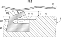
- the seal member 2 includes a substantially trapezoidal first element 21 in a cross sectional view and a second element 22 located in the upper part of the first element 21 and having a substantially L shape in a cross sectional view (FIG. 2 reference).
- the second element 22 has a gap 20 with respect to the first element 21 and is connected to the first element 21 at its proximal end.
- the length L of the second element 22 is included in the range of 2.0 to 20 mm
- the thickness T of the second element 22 is in the range of 0.1 to 2.0 mm
- the seal member 2 may be configured such that the protrusion height H of the second element 22 is included in the range of 1.0 to 9.0 [mm] with reference to the suction plane.
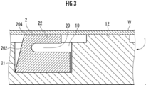
- the second element 22 is configured to be elastically tiltable to the same height as the contact portion (suction plane) with the wafer W on the surface of the substrate 1 so as to narrow the gap 20 present between the second element 22 and the first element 21. (See Figure 3).
- the seal member 2 is required to have elasticity to restore its original posture or configuration. Taking this point into consideration, the hardness of the material constituting the seal member 2 and the thickness of the bending point or proximal end of the second element 22 are designed.
- a gap having an opening on the surface side of the base 1 is formed.
- the seal member 2 is configured such that the upper inclined surface of the second element 22 is inclined upward continuously from the flat upper end surface 204 of the seal member 2.
- each of the sealing member 2 and the annular recess 10 may be variously changed.
- the seal member 2 may be torus shaped.
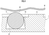
- the seal member 2 has a substantially circular shape in a cross sectional view, and the upper end portion of a portion (corresponding to the second element 22) protruding above the suction plane of the base 1 is in contact with the substrate (wafer W).
- the contact part which contacts is comprised.
- the annular recess 10 may be formed to have a generally trapezoidal cross-section with the upper bottom on the upper side. In other words, the inner side surface of the annular recess 10 may be inclined toward the bottom of the annular recess 10.
- the cross-sectional shape of the sealing member 2 may be a bellows shape (not shown) in which the axial direction extends in the vertical direction.
- the cross-sectional shape of the annular recess 10 is a substantially trapezoidal shape, and the seal member 2 has an annular protrusion, such as a shape (not shown) having one or more protrusions projecting inward from the lower end position to the upper end position. It may be of any shape that can prevent it from coming off part 10.
- the appearance of the seal member 2 is formed in a torus shape as in FIG. 4, but in a cross sectional view, the lower semicircular arc first element 21 and the upper semicircular arc And the second element 22 of
- the seal member 2 shown in FIG. 5 is formed of a hollow member.
- the hollow member may be configured of a U-shaped first element opened upward and a U-shaped second element opened downward.
- the seal member 2 may be formed to have a cross section of The seal member 2 may have a substantially U-shape (a shape in which the L-shape is turned upside-down) in a cross sectional view, and the annular recess 10 has a vertically elongated rectangular upper end in which the seal member 21 is accommodated. In the part, a horizontally long rectangular shape extending in the lateral direction is continuous.
- the seal member 2 may have no flat upper end surface 204 (see FIG. 2), and the upper end surface may be formed only by an inclined surface.
- the upper inclined surface of the second element 22 may not be inclined at a uniform angle, but may be formed so that the inclination angle gradually decreases or increases.
- the second element 22 constituting the seal member 2 is inclined to the upper side (outer edge side) and upper side of the base 1 (see FIG. 2), but may be inclined to the upper side (central side) and upper side of the base 1 .
- the inner side surface 202 of the seal member 2 and the inner side surface of the annular recess 10 may be in contact with each other, and the gap between the two may not be provided.
- each of the annular recess 10, the seal member 2 and the annular protrusion 12 in the vacuum chuck of the above embodiment is formed in a substantially annular shape, it may be an elliptical annular shape, a rectangular annular shape, a frame shape or a large number according to the shape of the wafer W.
- the shape may be changed into any shape as long as it is an annular shape such as a rectangular annular shape.
- the annular convex portion 12 may be omitted in the above embodiment.
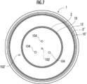
- an outer annular recess 10 ' is formed on the surface of the base 1 in place of the annular projection 12 as shown in FIG. 7, and an outer seal member 2' having the same configuration as that described above. May be arranged. That is, an outer seal is formed on the surface of the base 1 with a plurality of annular recesses 10, the seal member 2 is disposed in each of the plurality of annular recesses 10, and is disposed in the outer annular recess 10 'in which the inner annular recess 10 is present. At least a part of the second element 22 (see FIG. 2) constituting the member 2 ′ may form the annular convex portion.
- the base 1 may have a communication passage 102 'formed between the inner seal member 2 and the outer seal member 2'.
- the second element 22 which is a part of the inner seal member 2 and the second which is a part of the outer seal member 2 ′
- the element is elastically deformed by receiving a load from the wafer W. Therefore, even if the wafer W is warped or undulated, each of the second elements can be brought into contact with the wafer W over the entire circumference or substantially the entire circumference.
- the space (inner space) enclosed by the base 1 and the inner seal member 2 is vacuum suctioned, and the wafer W, the base 1, the inner seal member 2 and the outer seal member 2 ′ are further passed through the outer communication path 102 ′.
- the annular space (outer space) enclosed by the and is evacuated.
- a negative pressure region is formed in the inner space, and the second element 22 of the inner seal member 2 and the second element of the outer seal member 2 ′ are further elastically deformed to the same height as the suction surface of the substrate 1. (See Figure 3).
- the wafer W can be entirely brought into contact with the contact portion of the surface of the substrate 1, and further, the area of the wafer W where the flatness is secured can be expanded.
- the inner seal member 2 is installed in addition to the outer seal member 2 ', not only the wafer W having a relatively large diameter (for example, 12 inches in diameter) corresponding to the outer seal member 2' but also the inner seal member 2
- the wafer W having a relatively small diameter (for example, 8 inches in diameter) can also be vacuum suctioned.
- the inner seal member 2 is reliably abutted against the wafer W
- the pressure in the inner space is corrected so that the wafer W becomes flat.
- the outer seal member 2 ′ can be brought into contact with the wafer W over the entire circumference, so that the flatness of the wafer W can be improved by reducing the pressure in the outer space.
- the annular convex portion 12 may be omitted.
Landscapes
- Container, Conveyance, Adherence, Positioning, Of Wafer (AREA)
Abstract
反りまたはうねりなどが存在するウエハ等の基板を吸着保持する際、基板の平坦度が担保される領域の拡張を図りうる真空チャックを提供する。 基体1の表面に連通経路102を囲う環状に窪んでいる環状凹部10が形成されている。環状凹部10に環状のシール部材2が配置されている。シール部材2は、その一部である第2要素22が、環状凹部10から基体1の表面における基板との当接箇所(またはそれらにより定義される吸着平面)より上方に突出するように構成されている。シール部材2は、第2要素22が第1要素21との間に存在する間隙20を狭めるように基体1の表面におけるウエハWとの当接箇所と同じ高さまで傾倒可能になるような弾性を有している。
Description
本発明は、基体に形成されている連通経路を通じて形成される負圧によってウエハ等の基板を当該基体の表面に吸着保持する真空チャックに関する。
基体の外縁に、弾性材料(たとえばゴム)からなり、下から上にかけて徐々に外側に広がるように形成されているスカート状のシール部材が設けられた真空チャックが提案されている(特許文献1参照)。 板状部材にシール部材が固定され、複数の当該板状部材が基体に対して取り外し可能に固定される構成の真空チャックが提案されている(特許文献2参照)。
当該構成の真空チャックによれば、ウエハに反り、うねりまたは段差が存在する場合でも、シール部材の上端部をその全周にわたって当該ウエハに当接させ、ウエハと吸着面との間隙に密閉領域が形成される。このため、ウエハの反り等によって基体との間に本来的に生じる間隙の影響を解消して、当該密閉領域を負圧として当該ウエハが確実に吸着保持される。
しかし、ウエハにおいてシール部材との当接箇所および当接箇所(たとえば最も外側にある当接箇所)よりも外側の領域については平坦度が担保されない場合があるため、ウエハに可能な限り多くの回路チップを製造する等のウエハの有効活用の観点から改善の余地がある。
そこで、本発明は、反りまたはうねりなどが存在するウエハ等の基板を吸着保持する際、基板の平坦度が担保される領域の拡張を図りうる真空チャックを提供することを目的とする。
本発明は、連通経路が形成されている基体を備え、前記連通経路を通じて前記基体の表面と基板との間に負圧領域が形成されることにより前記基体の表面側に前記基板を吸着保持するように構成されている真空チャックに関する。
本発明の第1態様の真空チャックは、前記基体の表面に前記連通経路を囲う環状に窪んでいる環状凹部が形成され、前記環状凹部に環状の弾性素材からなるシール部材が配置され、前記シール部材の一部が前記基体の吸着平面より突出し、かつ、弾性的に変形可能に構成されていることを特徴とする。
本発明の第1態様の真空チャックによれば、基板が基体の表面側に載置された際、シール部材の一部が弾性的に変形して、基板に反りまたはうねりなどがあっても、当該一部を全周またはほぼ全周にわたり基板に対して当接させることができる。なお、基板の反り態様としては、当該基板が鞍形またはドーム型に変形している態様があげられる。基板の中央部がその周辺部よりも上方にある中凸態様の変形のほか、中央部がその周辺部よりも下方にある中凹態様の変形も含まれる。そして、連通経路を通じて基板と、基体と、シール部材とにより囲まれている空間(内側空間)が真空吸引されることにより、当該内側空間に負圧領域が形成され、シール部材の当該一部がさらに弾性的に変形して基体の吸着表面(基体の表面に形成された構造物の上端の点または面を包含する仮想的な平面)と同じ高さとなる。これにより、基板を全体的に基体の表面に形成された構造物またはそれらとの当接箇所に当接させることができ、当該基板において平坦度が担保される領域の拡張が図られる。
本発明の第1態様の真空チャックにおいて、前記シール部材が、前記環状凹部に配置される環状の第1要素と、少なくとも一部が前記環状凹部から前記吸着平面より上方に突出するように傾斜して延在している環状の第2要素と、を備え、前記第2要素が前記基体の表面における前記吸着平面と同じ高さまで弾性的に傾倒可能に構成されている。
当該構成の真空チャックによれば、連通経路を通じて内側空間が真空吸引されることにより、当該内側空間に負圧領域が形成され、シール部材の一部である第2要素が弾性的に傾倒して第1要素との間に存在する間隙が狭まるように基体の吸着表面と同じ高さとなる。これにより、基板を全体的に基体の表面に形成された構造物またはそれらとの当接箇所に当接させることができ、当該基板において平坦度が担保される領域の拡張が図られる。
本発明の第2態様の真空チャックは、前記基体の表面に前記連通経路を囲う環状に窪んでいる環状凹部が形成され、前記環状凹部に環状の弾性素材からなるシール部材が配置され、前記シール部材が、環状凹部に収まるように配置される下側の第1要素と、一端部または基端部が前記第1要素に対して固定または接続され、その他端部において前記基板に当接する上側の第2要素と、を備え、前記第2要素の他端部は、前記基板を吸着保持していない状態では、吸着平面よりも上方側に位置していることを特徴とする。
本発明の第2態様の真空チャックによれば、基板が基体の表面側に載置された際、シール部材のうち少なくとも第2要素が弾性的に変形して、基板に反りまたはうねりなどがあっても、当該第2要素の他端部(当接部)を全周またはほぼ全周にわたり基板に対して当接させることができる。そして、連通経路を通じて基板と、基体と、シール部材とにより囲まれている空間(内側空間)が真空吸引されることにより、当該内側空間に負圧領域が形成され、シール部材のうち少なくとも第2要素がさらに弾性的に変形して基体の吸着表面と同じ高さとなる。これにより、基板を全体的に基体の表面に形成された構造物またはそれらとの当接箇所に当接させることができ、当該基板において平坦度が担保される領域の拡張が図られる。
本発明の第2態様の真空チャックにおいて、前記第1要素および前記第2要素の間に間隙が存在するように前記シール部材が構成されていることが好ましい。本発明の第2態様の真空チャックにおいて、前記第1要素および前記第2要素の間に外部に開放されている間隙が存在するように前記シール部材が構成されていることが好ましい。
当該構成の真空チャックによれば、第1要素および第2要素の間隙の形態が変化するようにシール部材が弾性的に変化することにより、上記のように基板を全体的に基体の表面に形成された構造物またはそれらとの当接箇所に当接させることができ、当該基板において平坦度が担保される領域の拡張が図られる。
(構成)
図1および図2に示されている本発明の一実施形態としての真空チャックは、略円板状のセラミックス焼結体からなる基体1を備えている。基体1は、炭化珪素、窒化アルミニウム、アルミナまたは窒化ケイ素などのセラミックス粉末を主原料とする原料粉末の成形体が焼成され、必要な加工が施されることにより作製される。
図1および図2に示されている本発明の一実施形態としての真空チャックは、略円板状のセラミックス焼結体からなる基体1を備えている。基体1は、炭化珪素、窒化アルミニウム、アルミナまたは窒化ケイ素などのセラミックス粉末を主原料とする原料粉末の成形体が焼成され、必要な加工が施されることにより作製される。
基体1には、連通経路102(貫通孔)のほか、ウエハW(基板)を昇降させるためのリフトピン(図示略)が挿通されるリフトピン用貫通孔104が形成されている。基体1の表面に連通経路102を囲う環状に窪んでいる環状凹部10(たとえば深さ1~10[mm]、幅1~10[mm])が形成されている。環状凹部10に環状のシール部材2が配置されている。
基体1には、環状凹部10を囲う環状に突出している環状凸部12(たとえば高さ30~200[μm])が形成されている。環状凸部12の上端部が基体1における「ウエハWとの当接箇所」を構成する。そのほか、基体1の吸着面には、当該吸着面から突出する略円柱状、略半球状または略円錐台状の複数のピン(図示略(たとえば高さ30~200[μm]))が、三角格子状、正方格子状または同心円状など、規則的に配置されて形成されていてもよい。複数のピンの上端部が基体1における「ウエハWとの当接箇所」を構成し、かつ、吸着平面を定義する。図2では、基体1の上端面または表面が平坦面であるかのように示されているが、実際には環状凸部12の上端面および各ピンの上端面により構成される離散的な面の集合である。
シール部材2は、環状の部材であって、ウレタンまたはフッ素ゴムなどの弾性素材により構成されている。シール部材2は、下側の第1要素21と、上側の第2要素22と、を備えている。シール部材2において、下側の第1要素21は、その全部が環状凹部10に収まるように配置される。シール部材2において、上側の第2要素22は、その一端部または基端部が第1要素21に対して固定または接続され、その他端部において基板(ウエハW)に当接する。第2要素22の他端部は、基板(ウエハW)を吸着保持していない状態では、吸着平面よりも上方側に位置している。第2要素22を構成する材料としては、その硬度が0~60の材料が採用される。第1要素21を構成する材料の硬度が、第2要素22を構成する材料の硬度と同一であってもよく、異なっていてもよい。硬度はデュロメーターを用いて、JIS K6253:2012に基づいて測定される。
シール部材2は、断面視で、略台形状の第1要素21と、第1要素21の上部に位置し、断面視で略L字状の第2要素22と、を備えている(図2参照)。第2要素22は、第1要素21に対して間隙20を有し、その基端部において第1要素21に接続されている。例えば、断面視において、第2要素22の長さLが2.0~20[mm]の範囲に含まれ、第2要素22の厚さTが0.1~2.0[mm]の範囲に含まれ、かつ、吸着平面を基準とした第2要素22の突出高さHが1.0~9.0[mm]の範囲に含まれるようにシール部材2が構成されていてもよい。
第2要素22が、第1要素21との間に存在する間隙20を狭めるように基体1の表面におけるウエハWとの当接部(吸着平面)と同じ高さまで弾性的に傾倒可能に構成されている(図3参照)。第2要素22が、荷重がある状態から当該荷重から解放された状態に遷移した際に、元の姿勢または形態に復元するような弾性がシール部材2に必要とされる。この点が勘案されて、シール部材2を構成する素材の硬度および第2要素22の撓み箇所または基端の厚みが設計される。シール部材2の側面202と環状凹部10の内側面との間に基体1の表面側に開放部を備えている間隙が形成されている。シール部材2は、第2要素22の上側の傾斜面がシール部材2の平坦な上端面204から連続して上方に傾斜するように構成されている。
(機能)
前記構成の真空チャックによれば、ウエハWが基体1の表面側に載置された際、シール部材2の一部である第2要素22を、ウエハWに反りまたはうねりなどがあっても全周またはほぼ全周にわたりウエハWに対して当接させることができる。そして、連通経路102を通じてウエハWと、基体1と、シール部材2とにより囲まれている空間(内側空間)が真空吸引される。これにより、当該内側空間に負圧領域が形成され、シール部材2が、その第2要素22が弾性的に傾倒するように弾性的に変形して基体1の吸着平面と同じまたはほぼ同じ高さとなる(図3参照)。その結果、ウエハWを全体的に基体1の吸着表面に当接させることができ、さらには当該ウエハWにおいて平坦度が担保される領域の拡張が図られる。
前記構成の真空チャックによれば、ウエハWが基体1の表面側に載置された際、シール部材2の一部である第2要素22を、ウエハWに反りまたはうねりなどがあっても全周またはほぼ全周にわたりウエハWに対して当接させることができる。そして、連通経路102を通じてウエハWと、基体1と、シール部材2とにより囲まれている空間(内側空間)が真空吸引される。これにより、当該内側空間に負圧領域が形成され、シール部材2が、その第2要素22が弾性的に傾倒するように弾性的に変形して基体1の吸着平面と同じまたはほぼ同じ高さとなる(図3参照)。その結果、ウエハWを全体的に基体1の吸着表面に当接させることができ、さらには当該ウエハWにおいて平坦度が担保される領域の拡張が図られる。
(本発明の他の実施形態)
シール部材2および環状凹部10のそれぞれの形状がさまざまに変更されてもよい。たとえば、図4に示されているように、シール部材2はトーラス状であってもよい。シール部材2は、断面視で、略円形状であり、基体1の吸着平面よりも上方に突出している部分(第2要素22に相当する。)の上端部が、基板(ウエハW)と当接する当接部を構成する。同じく図4に示されているように、環状凹部10が上側に上底がある略台形状の断面を有するように形成されていてもよい。言い換えると、環状凹部10の内側面が、環状凹部10の底面側に傾斜した形態であってもよい。このような形態によれば、断面視で、環状凹部10の底面側の幅が断面視で上辺側の幅よりも大きいため、シール部材2が環状凸部10から外れてしまう事態が防止される。なお、シール部材2の断面形状が、軸線方向が上下方向に延在する、蛇腹形状(ベローズ形状)であってもよい(図示略)。環状凹部10の断面形状は、略台形状のほか、下端位置から上端位置に至る途中で内側に突出する一または複数の凸部を有するような形状(図示略)など、シール部材2が環状凸部10から外れることを防止しうるあらゆる形状であってもよい。
シール部材2および環状凹部10のそれぞれの形状がさまざまに変更されてもよい。たとえば、図4に示されているように、シール部材2はトーラス状であってもよい。シール部材2は、断面視で、略円形状であり、基体1の吸着平面よりも上方に突出している部分(第2要素22に相当する。)の上端部が、基板(ウエハW)と当接する当接部を構成する。同じく図4に示されているように、環状凹部10が上側に上底がある略台形状の断面を有するように形成されていてもよい。言い換えると、環状凹部10の内側面が、環状凹部10の底面側に傾斜した形態であってもよい。このような形態によれば、断面視で、環状凹部10の底面側の幅が断面視で上辺側の幅よりも大きいため、シール部材2が環状凸部10から外れてしまう事態が防止される。なお、シール部材2の断面形状が、軸線方向が上下方向に延在する、蛇腹形状(ベローズ形状)であってもよい(図示略)。環状凹部10の断面形状は、略台形状のほか、下端位置から上端位置に至る途中で内側に突出する一または複数の凸部を有するような形状(図示略)など、シール部材2が環状凸部10から外れることを防止しうるあらゆる形状であってもよい。
図5に示されているように、シール部材2の外観は、図4と同様にトーラス状に形成されているが、断面視で、下半円弧状の第1要素21と、上半円弧状の第2要素22と、により構成されていてもよい。言い換えると、図5に示されているシール部材2は、中空の部材により構成されている。図示しないが、中空の部材が、上に開口したU字状の第1要素と、下に開口したU字状の第2要素と、により構成されていてもよい。
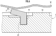
図6に示されているように、第1要素21が縦長の略矩形状の断面を有し、第2要素22が第1要素21の上部から連続して斜め上方に延在する略矩形状の断面を有するようにシール部材2が形成されていてもよい。また、シール部材2は、断面視で略Γ字形状(L字をさかさまにしたような形状)であってもよく、環状凹部10が、シール部材21が収容される縦長の矩形状の上端部に、横方向に延在する横長の矩形状が連続する。
たとえば、シール部材2に平坦な上端面204(図2参照)がなく、その上端面が傾斜面のみによって構成されていてもよい。第2要素22の上側傾斜面が一様な角度で傾斜するのではなく、当該傾斜角度が徐々に減少するまたは増加するような形状に形成されてもよい。シール部材2を構成する第2要素22は、基体1の外側(外縁側)上方に傾斜しているが(図2参照)、基体1の内側(中心部側)上方に傾斜していてもよい。シール部材2の内側面202と環状凹部10の内側面とが当接して両者の間隙が設けられていなくてもよい。
上記実施形態の真空チャックにおける環状凹部10、シール部材2および環状凸部12のそれぞれは略円環状に形成されているが、ウエハWの形状に合わせて楕円環状、矩形環状、枠状または正多角形環状など、環状であれば任意の形状に変更されてもよい。
上記実施形態において環状凸部12が省略されてもよい。シール部材10との当接箇所によって囲まれている内側領域の反りまたはひずみ等が平坦に矯正されることにより、当該内側領域よりも外側にある外側領域の反り等も平坦に矯正されうる。
上記実施形態において基体1の表面に環状凸部12に代えて、図7に示されているように外側環状凹部10’が形成されたうえでそこに上記と同様の構成の外側シール部材2’が配置されてもよい。すなわち、基体1の表面に複数の環状凹部10が形成され、複数の環状凹部10のそれぞれにシール部材2が配置され、内側環状凹部10が存在する外側環状凹部10’に配置されている外側シール部材2’を構成する第2要素22(図2参照)の少なくとも一部が当該環状凸部を形成していてもよい。基体1には、内側シール部材2および外側シール部材2’の間に、連通経路102’が形成されていてもよい。
当該構成の真空チャックによれば、ウエハWが基体1の表面側に載置された際、内側シール部材2の一部である第2要素22および外側シール部材2’の一部である第2要素がウエハWから荷重を受けることで弾性的に変形する。このため、ウエハWに反りまたはうねりなどがあっても、第2要素のそれぞれを全周またはほぼ全周にわたりウエハWに対して当接させることができる
そして、内側連通経路102を通じてウエハWと、基体1と、内側シール部材2とにより囲まれている空間(内側空間)が真空吸引され、さらに、外側連通経路102’を通じてウエハWと、基体1と、内側シール部材2および外側シール部材2’とにより囲まれている環状の空間(外側空間)が真空吸引される。これにより、当該内側空間に負圧領域が形成され、内側シール部材2の第2要素22および外側シール部材2’の第2要素がさらに弾性的に変形して基体1の吸着表面と同じ高さとなる(図3参照)。その結果、ウエハWを全体的に基体1の表面の当接箇所に当接させることができ、さらには当該ウエハWにおいて平坦度が担保される領域の拡張が図られる。
そして、内側連通経路102を通じてウエハWと、基体1と、内側シール部材2とにより囲まれている空間(内側空間)が真空吸引され、さらに、外側連通経路102’を通じてウエハWと、基体1と、内側シール部材2および外側シール部材2’とにより囲まれている環状の空間(外側空間)が真空吸引される。これにより、当該内側空間に負圧領域が形成され、内側シール部材2の第2要素22および外側シール部材2’の第2要素がさらに弾性的に変形して基体1の吸着表面と同じ高さとなる(図3参照)。その結果、ウエハWを全体的に基体1の表面の当接箇所に当接させることができ、さらには当該ウエハWにおいて平坦度が担保される領域の拡張が図られる。
外側シール部材2’に加えて内側シール部材2が設置されているので、外側シール部材2’に対応した比較的大径(たとえば径12インチ)のウエハWのみならず、内側シール部材2に対応した比較的小径(たとえば径8インチ)のウエハWをも真空吸着可能である。また、外側シール部材2’をウエハWに対して全周にわたって当接させることができない程度に当該ウエハWが極端に反っていても、内側シール部材2をウエハWに対して確実に当接させ、内側空間の減圧によってウエハWが平坦になるように矯正される。これにより、外側シール部材2’をウエハWに対して全周にわたって当接させることができるので、外側空間の減圧によってウエハWの平坦性の向上が図られる。
前記実施形態の真空チャックにおいて、環状凸部12は省略されてもよい。
1‥基体、2‥シール部材、10‥環状凹部、12‥環状凸部、20‥第1および第2要素の間隙、21‥第1要素、22‥第2要素、102‥連通経路、104‥リフトピン用貫通孔。
Claims (5)
- 連通経路が形成されている基体を備え、前記連通経路を通じて前記基体の表面と基板との間に負圧領域が形成されることにより前記基体の表面側に前記基板を吸着保持するように構成されている真空チャックであって、
前記基体の表面に前記連通経路を囲う環状に窪んでいる環状凹部が形成され、
前記環状凹部に環状の弾性素材からなるシール部材が配置され、
前記シール部材の一部が前記基体の吸着平面より突出し、かつ、弾性的に変形可能に構成されていることを特徴とする真空チャック。 - 請求項1記載の真空チャックにおいて、
前記シール部材が、前記環状凹部に配置される環状の第1要素と、少なくとも一部が前記環状凹部から前記吸着平面より上方に突出するように傾斜して延在している環状の第2要素と、を備え、前記第2要素が前記基体の表面における前記吸着平面と同じ高さまで弾性的に傾倒可能に構成されていることを特徴とする真空チャック。 - 連通経路が形成されている基体を備え、前記連通経路を通じて前記基体の表面と基板との間に負圧領域が形成されることにより前記基体の表面側に前記基板を吸着保持するように構成されている真空チャックであって、
前記基体の表面に前記連通経路を囲う環状に窪んでいる環状凹部が形成され、
前記環状凹部に環状の弾性素材からなるシール部材が配置され、
前記シール部材が、環状凹部に収まるように配置される下側の第1要素と、一端部または基端部が前記第1要素に対して固定または接続され、その他端部において前記基板に当接する上側の第2要素と、を備え、
前記第2要素の他端部は、前記基板を吸着保持していない状態では、吸着平面よりも上方側に位置していることを特徴とする真空チャック。 - 請求項3記載の真空チャックにおいて、
前記第1要素および前記第2要素の間に間隙が存在するように前記シール部材が構成されていることを特徴とする真空チャック。 - 請求項4記載の真空チャックにおいて、
前記第1要素および前記第2要素の間に外部に開放されている間隙が存在するように前記シール部材が構成されていることを特徴とする真空チャック。
Priority Applications (2)
| Application Number | Priority Date | Filing Date | Title |
|---|---|---|---|
| JP2017516529A JPWO2017086333A1 (ja) | 2015-11-19 | 2016-11-16 | 真空チャック |
| CN201680017024.5A CN107408530A (zh) | 2015-11-19 | 2016-11-16 | 真空卡盘 |
Applications Claiming Priority (2)
| Application Number | Priority Date | Filing Date | Title |
|---|---|---|---|
| JP2015-227043 | 2015-11-19 | ||
| JP2015227043 | 2015-11-19 |
Publications (1)
| Publication Number | Publication Date |
|---|---|
| WO2017086333A1 true WO2017086333A1 (ja) | 2017-05-26 |
Family
ID=58718963
Family Applications (1)
| Application Number | Title | Priority Date | Filing Date |
|---|---|---|---|
| PCT/JP2016/083923 Ceased WO2017086333A1 (ja) | 2015-11-19 | 2016-11-16 | 真空チャック |
Country Status (4)
| Country | Link |
|---|---|
| JP (1) | JPWO2017086333A1 (ja) |
| CN (1) | CN107408530A (ja) |
| TW (1) | TW201727815A (ja) |
| WO (1) | WO2017086333A1 (ja) |
Cited By (16)
| Publication number | Priority date | Publication date | Assignee | Title |
|---|---|---|---|---|
| CN107591356A (zh) * | 2017-10-13 | 2018-01-16 | 深圳中科飞测科技有限公司 | 晶圆固定装置及其使用方法 |
| JP2019004017A (ja) * | 2017-06-14 | 2019-01-10 | 日本特殊陶業株式会社 | 真空チャック |
| JP2019145827A (ja) * | 2018-02-21 | 2019-08-29 | 住友電気工業株式会社 | ウエハ保持台 |
| CN110346609A (zh) * | 2018-04-03 | 2019-10-18 | 爱思开海力士有限公司 | 晶片卡紧装置和包括其的晶片测试设备 |
| JP2020080390A (ja) * | 2018-11-14 | 2020-05-28 | 株式会社ディスコ | チャックテーブル及び加工装置 |
| CN113262951A (zh) * | 2020-02-14 | 2021-08-17 | 株式会社斯库林集团 | 基板处理装置及基板处理方法 |
| JP2022113293A (ja) * | 2021-01-25 | 2022-08-04 | 株式会社東京精密 | 真空チャック及びそれを備える検査装置 |
| CN114864470A (zh) * | 2022-04-27 | 2022-08-05 | 苏州科韵激光科技有限公司 | 一种晶圆片的固定载具 |
| US20220319903A1 (en) * | 2021-03-31 | 2022-10-06 | Taiwan Semiconductor Manufacturing Company, Ltd. | Apparatus and method for substrate handling |
| JP2022165213A (ja) * | 2021-04-19 | 2022-10-31 | 三菱電機株式会社 | 検査装置、半導体基板の検査方法、半導体基板の製造方法、および半導体装置の製造方法 |
| US20230061549A1 (en) * | 2021-08-30 | 2023-03-02 | Taiwan Semiconductor Manufacturing Company Ltd. | Method and device for placing semiconductor wafer |
| JP2023076260A (ja) * | 2021-11-22 | 2023-06-01 | 株式会社ディスコ | ウェーハ保持具 |
| CN116447213A (zh) * | 2023-05-12 | 2023-07-18 | 深圳市倍思科技有限公司 | 一种具有限位凹槽的吸盘 |
| CN120261379A (zh) * | 2025-06-03 | 2025-07-04 | 浙江中科尚弘离子装备工程有限公司 | 一种用于晶圆加工的靶盘组件 |
| US12386273B2 (en) | 2019-08-20 | 2025-08-12 | Asml Netherlands B.V. | Substrate holder, lithographic apparatus and method |
| JP2026054118A (ja) * | 2024-09-13 | 2026-03-26 | 株式会社Screenホールディングス | 基板処理装置および基板処理方法 |
Families Citing this family (5)
| Publication number | Priority date | Publication date | Assignee | Title |
|---|---|---|---|---|
| CN115480452B (zh) * | 2021-05-31 | 2024-11-12 | 上海微电子装备(集团)股份有限公司 | 一种吸盘组件、曝光装置及光刻系统 |
| TWI850820B (zh) * | 2021-10-29 | 2024-08-01 | 由田新技股份有限公司 | 基板承載結構以及基板檢測裝置 |
| TWI804164B (zh) * | 2022-01-18 | 2023-06-01 | 由田新技股份有限公司 | 整平裝置及整平方法 |
| CN114582778A (zh) * | 2022-02-15 | 2022-06-03 | 睿励科学仪器(上海)有限公司 | 一种针对大翘曲度样品的吸附系统及吸附方法 |
| CN116544169A (zh) * | 2023-04-23 | 2023-08-04 | 晶诺微(上海)科技有限公司 | 一种晶圆吸附装置及晶圆吸附方法 |
Citations (3)
| Publication number | Priority date | Publication date | Assignee | Title |
|---|---|---|---|---|
| JP2004228453A (ja) * | 2003-01-27 | 2004-08-12 | Renesas Technology Corp | 半導体装置の製造方法 |
| JP2005528794A (ja) * | 2002-05-31 | 2005-09-22 | エイエスエム・ナトゥール・インコーポレーテッド | 全面電気化学めっきのためにウェハの裏側をシールする方法及び装置 |
| JP2014072510A (ja) * | 2012-10-02 | 2014-04-21 | Disco Abrasive Syst Ltd | チャックテーブル |
-
2016
- 2016-11-16 WO PCT/JP2016/083923 patent/WO2017086333A1/ja not_active Ceased
- 2016-11-16 CN CN201680017024.5A patent/CN107408530A/zh not_active Withdrawn
- 2016-11-16 JP JP2017516529A patent/JPWO2017086333A1/ja active Pending
- 2016-11-18 TW TW105137742A patent/TW201727815A/zh unknown
Patent Citations (3)
| Publication number | Priority date | Publication date | Assignee | Title |
|---|---|---|---|---|
| JP2005528794A (ja) * | 2002-05-31 | 2005-09-22 | エイエスエム・ナトゥール・インコーポレーテッド | 全面電気化学めっきのためにウェハの裏側をシールする方法及び装置 |
| JP2004228453A (ja) * | 2003-01-27 | 2004-08-12 | Renesas Technology Corp | 半導体装置の製造方法 |
| JP2014072510A (ja) * | 2012-10-02 | 2014-04-21 | Disco Abrasive Syst Ltd | チャックテーブル |
Cited By (24)
| Publication number | Priority date | Publication date | Assignee | Title |
|---|---|---|---|---|
| JP2019004017A (ja) * | 2017-06-14 | 2019-01-10 | 日本特殊陶業株式会社 | 真空チャック |
| CN107591356A (zh) * | 2017-10-13 | 2018-01-16 | 深圳中科飞测科技有限公司 | 晶圆固定装置及其使用方法 |
| JP2019145827A (ja) * | 2018-02-21 | 2019-08-29 | 住友電気工業株式会社 | ウエハ保持台 |
| CN110346609A (zh) * | 2018-04-03 | 2019-10-18 | 爱思开海力士有限公司 | 晶片卡紧装置和包括其的晶片测试设备 |
| JP2020080390A (ja) * | 2018-11-14 | 2020-05-28 | 株式会社ディスコ | チャックテーブル及び加工装置 |
| US12386273B2 (en) | 2019-08-20 | 2025-08-12 | Asml Netherlands B.V. | Substrate holder, lithographic apparatus and method |
| JP2021129034A (ja) * | 2020-02-14 | 2021-09-02 | 株式会社Screenホールディングス | 基板処理装置および基板処理方法 |
| CN113262951A (zh) * | 2020-02-14 | 2021-08-17 | 株式会社斯库林集团 | 基板处理装置及基板处理方法 |
| JP2025100852A (ja) * | 2021-01-25 | 2025-07-03 | 株式会社東京精密 | 真空チャック及びそれを備える検査装置 |
| JP2022113293A (ja) * | 2021-01-25 | 2022-08-04 | 株式会社東京精密 | 真空チャック及びそれを備える検査装置 |
| JP7815519B2 (ja) | 2021-01-25 | 2026-02-17 | 株式会社東京精密 | 真空チャック及びそれを備える検査装置 |
| JP7676156B2 (ja) | 2021-01-25 | 2025-05-14 | 株式会社東京精密 | 真空チャック及びそれを備える検査装置 |
| US20220319903A1 (en) * | 2021-03-31 | 2022-10-06 | Taiwan Semiconductor Manufacturing Company, Ltd. | Apparatus and method for substrate handling |
| US12701968B2 (en) | 2021-04-19 | 2026-08-04 | Mitsubishi Electric Corporation | Inspection device, inspection method of semiconductor substrate, manufacturing method of semiconductor substrate, and manufacturing method of semiconductor device |
| JP2022165213A (ja) * | 2021-04-19 | 2022-10-31 | 三菱電機株式会社 | 検査装置、半導体基板の検査方法、半導体基板の製造方法、および半導体装置の製造方法 |
| JP7482825B2 (ja) | 2021-04-19 | 2024-05-14 | 三菱電機株式会社 | 検査装置、半導体基板の検査方法、半導体基板の製造方法、および半導体装置の製造方法 |
| US20230061549A1 (en) * | 2021-08-30 | 2023-03-02 | Taiwan Semiconductor Manufacturing Company Ltd. | Method and device for placing semiconductor wafer |
| US12550678B2 (en) * | 2021-08-30 | 2026-02-10 | Taiwan Semiconductor Manufacturing Company Ltd. | Method and device for placing semiconductor wafer |
| JP7798542B2 (ja) | 2021-11-22 | 2026-01-14 | 株式会社ディスコ | ウェーハ保持具 |
| JP2023076260A (ja) * | 2021-11-22 | 2023-06-01 | 株式会社ディスコ | ウェーハ保持具 |
| CN114864470A (zh) * | 2022-04-27 | 2022-08-05 | 苏州科韵激光科技有限公司 | 一种晶圆片的固定载具 |
| CN116447213A (zh) * | 2023-05-12 | 2023-07-18 | 深圳市倍思科技有限公司 | 一种具有限位凹槽的吸盘 |
| JP2026054118A (ja) * | 2024-09-13 | 2026-03-26 | 株式会社Screenホールディングス | 基板処理装置および基板処理方法 |
| CN120261379A (zh) * | 2025-06-03 | 2025-07-04 | 浙江中科尚弘离子装备工程有限公司 | 一种用于晶圆加工的靶盘组件 |
Also Published As
| Publication number | Publication date |
|---|---|
| JPWO2017086333A1 (ja) | 2017-11-16 |
| TW201727815A (zh) | 2017-08-01 |
| CN107408530A (zh) | 2017-11-28 |
Similar Documents
| Publication | Publication Date | Title |
|---|---|---|
| JPWO2017086333A1 (ja) | 真空チャック | |
| JP6725326B2 (ja) | 真空チャック及び真空チャックの製造方法 | |
| JP6546550B2 (ja) | 真空吸着部材および真空吸着方法 | |
| TWI690017B (zh) | 基板保持裝置 | |
| JP6894772B2 (ja) | 真空チャック | |
| KR102071123B1 (ko) | 기판유지장치, 기판유지부재 및 기판유지방법 | |
| JP2017135331A (ja) | 基板保持装置 | |
| JP6325933B2 (ja) | 真空チャック | |
| JP2019145827A (ja) | ウエハ保持台 | |
| JP6789006B2 (ja) | 真空吸着装置 | |
| JP7021969B2 (ja) | 真空吸着部材および真空吸着方法 | |
| JP6680649B2 (ja) | 真空吸着部材 | |
| JP6711721B2 (ja) | 真空吸着部材 | |
| JP6581495B2 (ja) | 基板保持装置 | |
| US10748805B2 (en) | Vacuum attraction member | |
| JPWO2015115198A1 (ja) | 空気ばね装置及び空気ばね装置の製造方法 | |
| JP2017199790A (ja) | 真空吸着部材 | |
| JP7125326B2 (ja) | 基板保持部材 | |
| JP2020177952A (ja) | 基板保持部材 | |
| KR20240051058A (ko) | 기판 유지 부재 | |
| JP7190326B2 (ja) | 基板保持部材 | |
| JP2020012512A (ja) | 環状シール材 | |
| JP2023098194A (ja) | 基板保持部材 | |
| KR20220139748A (ko) | 기판 트레이 |
Legal Events
| Date | Code | Title | Description |
|---|---|---|---|
| ENP | Entry into the national phase |
Ref document number: 2017516529 Country of ref document: JP Kind code of ref document: A |
|
| 121 | Ep: the epo has been informed by wipo that ep was designated in this application |
Ref document number: 16866334 Country of ref document: EP Kind code of ref document: A1 |
|
| NENP | Non-entry into the national phase |
Ref country code: DE |
|
| 122 | Ep: pct application non-entry in european phase |
Ref document number: 16866334 Country of ref document: EP Kind code of ref document: A1 |