WO2017082124A1 - フロントサブフレーム構造 - Google Patents
フロントサブフレーム構造 Download PDFInfo
- Publication number
- WO2017082124A1 WO2017082124A1 PCT/JP2016/082476 JP2016082476W WO2017082124A1 WO 2017082124 A1 WO2017082124 A1 WO 2017082124A1 JP 2016082476 W JP2016082476 W JP 2016082476W WO 2017082124 A1 WO2017082124 A1 WO 2017082124A1
- Authority
- WO
- WIPO (PCT)
- Prior art keywords
- tension rod
- rod support
- stabilizer
- support portion
- sub
- Prior art date
- Legal status (The legal status is an assumption and is not a legal conclusion. Google has not performed a legal analysis and makes no representation as to the accuracy of the status listed.)
- Ceased
Links
Images






Classifications
-
- B—PERFORMING OPERATIONS; TRANSPORTING
- B62—LAND VEHICLES FOR TRAVELLING OTHERWISE THAN ON RAILS
- B62D—MOTOR VEHICLES; TRAILERS
- B62D21/00—Understructures, i.e. chassis frame on which a vehicle body may be mounted
- B62D21/11—Understructures, i.e. chassis frame on which a vehicle body may be mounted with resilient means for suspension, e.g. of wheels or engine; sub-frames for mounting engine or suspensions
-
- B—PERFORMING OPERATIONS; TRANSPORTING
- B62—LAND VEHICLES FOR TRAVELLING OTHERWISE THAN ON RAILS
- B62D—MOTOR VEHICLES; TRAILERS
- B62D21/00—Understructures, i.e. chassis frame on which a vehicle body may be mounted
- B62D21/15—Understructures, i.e. chassis frame on which a vehicle body may be mounted having impact absorbing means, e.g. a frame designed to permanently or temporarily change shape or dimension upon impact with another body
- B62D21/152—Front or rear frames
- B62D21/155—Sub-frames or underguards
-
- B—PERFORMING OPERATIONS; TRANSPORTING
- B62—LAND VEHICLES FOR TRAVELLING OTHERWISE THAN ON RAILS
- B62D—MOTOR VEHICLES; TRAILERS
- B62D7/00—Steering linkage; Stub axles or their mountings
- B62D7/16—Arrangement of linkage connections
- B62D7/163—Arrangement of linkage connections substantially in axial direction, e.g. between rack bar and tie-rod
Definitions
- the technology disclosed in this specification relates to a front subframe structure disposed below the front side frame.
- a front subframe having a sub-crash can mounting portion, a tension rod support portion, and a cross member extending in the vehicle width direction so as to face the tension rod support portion from the inner side in the vehicle width direction has been known. It has been.
- a front sub-frame for example, as exemplified in Patent Document 1 below, a structure in which the crash rod (1e) is supported on the tension rod support portion (2), or exemplified in Patent Document 2 below.
- a front subframe structure including a steering rack (7) disposed below the tension rod support portion (1a) is provided. Proposed.
- the steering rack is arranged at almost the same height as the front subframe, but the tension is improved in order to improve the freedom of assembly from the lower side of the steering rack and the layout with other auxiliary equipment such as engines.
- the front subframe is also known to have a structure in which the subframe is offset (offset) upward with respect to the position of the subcrash can.
- the load transmission path from the front to the rear of the front subframe is displaced in the vertical direction at the time of a front collision or the like.
- the tension rod support portion is arranged at the front portion of the front subframe, the tension rod support portion and the tension rod support portion are secured while securing the tension rod support rigidity as described above. It has been difficult to lay out the side member, the stabilizer, and the steering rack in which the tension rod support portion extends rearward in a compact manner at the front portion of the front subframe.
- Patent Documents 1 and 2 described above a technical idea for improving the tension rod support rigidity while ensuring a compact layout of the tension rod support portion, the side member, the stabilizer, and the steering rack in the front subframe front portion. There was no disclosure, and there was room for further study.
- the technology disclosed in the present specification aims to increase tension rod support rigidity while making the front subframe front part a compact configuration.
- the front subframe structure of the technology disclosed in the present specification is provided with a pair of left and right front side frames that extend from the front of the vehicle compartment to the front side of the vehicle, and supports the front suspension device below the front side frame.
- a front subframe structure of an automobile provided with a subframe, wherein a tension rod support portion is provided at a front portion of the front subframe, and a side member is extended rearward from the tension rod support portion and rearward.
- a rack disposition stepped portion opened downward for disposing the steering rack is formed behind the tension rod support portion and below the side member, and a stabilizer support portion is provided on the rack disposition step portion.
- the tension rod support portion, the stabilizer support portion, and the steering rack are connected to the front and rear of the vehicle while increasing the tension rod support rigidity by arranging the stabilizer support portion at the rack arrangement step. Since it can arrange
- a sub-crash can mounting portion is provided in front of the tension rod support portion, and a closed cross section formed by a closed cross section extending between the rear surface of the tension rod support portion and the front surface of the side member and extending in the front-rear direction. It is preferable that a cross-sectional connection portion is provided, and the stabilizer support portion is fastened so as to connect the upper and lower surfaces of the closed cross-section connection portion.
- the stabilizer support portion is disposed between the rear surface of the tension rod support portion and the steering rack.
- the load when the concave portion is bent and deformed by the front impact load, the load can be dispersed backward by the stabilizer support portion and the steering rack disposed in the concave portion.
- the tension rod support rigidity can be increased while the front subframe front portion has a compact configuration.
- FIG. 1 is a perspective view of a front subframe of a vehicle according to an embodiment.
- FIG. 2 is a plan view of the front subframe.
- FIG. 3 is a bottom view of the front subframe.
- FIG. 4 is a left side view of the front subframe.
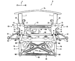
- FIG. 5 is a front view of the front subframe.
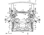
- FIG. 6 is a rear view of the front subframe.
- FIG. 7 is an explanatory diagram of the configuration of the braces of the front subframe.
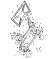
- FIG. 8 is an exploded perspective view of the front side of the front subframe.
- FIG. 9A is a configuration explanatory diagram of a subframe front structure.
- FIG. 9B is a configuration explanatory diagram of the subframe front structure.
- FIG. 10 is an explanatory diagram showing a fastening structure to the closed cross-section connecting portion of the stabilizer.
- FIG. 11A is a configuration explanatory diagram of a subframe front structure body.
- FIG. 11B is a configuration explanatory diagram of the subframe front structure body.
- FIG. 12A is a configuration explanatory diagram of the subframe front structure body.
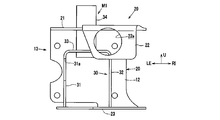
- FIG. 12B is a configuration explanatory diagram of the subframe front structure body.
- 1 to 7 show the front subframe structure of the automobile of this embodiment.
- FIG. 1 is a perspective view of the front subframe of the vehicle according to the present embodiment as seen from the diagonally upper left side
- FIG. 7 is an exploded view of the brace and the front subframe from which the brace is removed seen from below. A perspective view is shown.
- FIG. 4 shows the tension rod 51 and the lower arm 52.
- 5 and 6 omit the illustration of the sub-bumper reinforcement 7a, and FIG. 7 and FIG. 8 to be described later support the stabilizer in addition to the sub-bumper reinforcement 7a, the tension rod 51, and the lower arm 52.
- the illustration of the unit 62 and the stabilizer 100 is omitted.
- arrow F indicates the front of the vehicle
- arrow LE indicates the left in the vehicle width direction
- arrow RI indicates the right in the vehicle width direction
- arrow U indicates the upper side of the vehicle. Show.
- a dash panel 1 installed on the front part of the passenger compartment and a pair of left and right front side frames 2, 2 extending from the lower part of the dash panel 1 to the front side of the vehicle are disposed at the front of the automobile.
- a lower arm 52 (lateral) that extends substantially horizontally outward in the vehicle width direction for a strut type front suspension device is provided below the front side frame 2 as shown in FIGS.
- the front subframe 5 is disposed to support a rod (see FIGS. 1 and 2) and a tension rod 51 (see the same figure) extending from the lower arm 52 to the rear in the vehicle width direction.
- the front side frame 2 of the present embodiment extends in a horizontal direction 2a extending substantially horizontally along the front-rear direction of the vehicle in a side view, and inclined downwardly from the rear end portion along the lower end portion of the dash panel 1.
- a floor frame 3 extending to the rear side of the vehicle is connected to the rear end portion of the kick-up portion 2b (see FIG. 4).
- the front side frame 2 is provided with a crash can 4 made of a metal cylindrical body or the like protruding toward the front side of the vehicle, and the front end surface of the front side frame 2 extends in the vehicle width direction.
- a bumper reinforcement 4a is attached.
- the front sub-frame 5 mainly includes a pair of left and right side members 6 and 6 extending in the front-rear direction of the vehicle, a sub-crash can 7 extending in front of the side member 6, and a side
- the member 6 and the sub-crash can 7 are connected in the front-rear direction to connect the sub-frame front structure 10 (connecting member) constituting the front side of the front sub-frame 5 and the pair of left and right sub-frame front structures 10, 10.
- a suspension cross member 73 extending in the vehicle width direction (hereinafter referred to as “sus cross member 73”), and a rear cross member 74 extending in the vehicle width direction so as to connect the pair of left and right side members 6 and 6 to each other. Inclined members joined to these members 6, 6 and 74 behind the rear cross member 74 between the pair of side members 6 and 6 5 and and a brace 80.
- the front subframe 5 includes a front portion of the subframe front structure 10, a portion between the front and rear directions of the side member 6, and a rear end 3 of the side member 6.
- mount portions M1, M2, and M3 mount bushes and mount pipes 34
- mount portions M1, M2, and M3 mount bushes and mount pipes 34
- the first mount part M1 is connected to the front end of the horizontal part 2a of the front side frame 2 on the vehicle body side
- the second mount part M2 is connected at the rear part of the horizontal part 2a
- the mount portion M3 is connected to the front end of the floor frame 3 (a portion connected to the kick-up portion 2b).
- the front sub-frame 5 is mounted on the vehicle body at three points on one side in the front-rear direction and a total of six points on the left and right sides, and is disposed on the lower side of the vehicle body.
- the sub-crash can 7 is an impact energy absorbing member similar to the crash can 4 at the front end of the front side frame 2, and as shown in FIGS. 2 to 4, A sub-bumper reinforcement 7a extending in the vehicle width direction is provided so as to connect the front end portions.
- the side member 6 is installed below the pair of left and right front side frames 2 and the floor frame 3, and as shown in FIGS. It extends.
- the side member 6 includes a side member front portion 6a that is provided on the front side of the second mount portion M2 in the front-rear direction of the side member 6, and a side member rear portion 6b that is provided on the rear side of the second mount portion M2. (Not shown).
- the side member front portion 6a and the side member rear portion 6b both extend rearwardly and downwardly in a side view (see FIG. 4), but the side member front portion 6a is directed from the front end toward the second mount portion M2.
- the side member rear portion 6b extends in the front-rear direction so that the left and right sides are parallel to each other in plan view. (See the figure).
- the subframe front structure 10 is interposed between the subcrash can 7 and the side member 6, and the rear end bracket ( A sub-crash can mounting portion 12 as a set plate for mounting the rear end flange) 7b, a front vehicle body mounting portion 13, a tension rod support portion 14, and a closed cross-section connecting portion 15 are provided.
- the subframe front structure 10 is constructed by assembling a plurality of panel members into a three-dimensional shape as shown in FIGS. 8 to 12, and the subframe front structure body 20 and the tension rod support bracket 40 are closed. And a cross-sectional configuration panel 151.
- FIG. 8 is an exploded perspective view of the front sub-frame, in particular, the front sub-frame structure.
- Reference numeral 59 in FIG. 8 denotes a radiator support bracket.
- FIG. 9A is a perspective view of the left subframe front structure viewed from diagonally left 45 degrees
- FIG. 9B is a bottom view of the subframe front structure
- FIG. 10 is a front view of FIG. 9B in the front subframe.
- FIG. 11A is an enlarged cross-sectional view of a portion corresponding to line XX in FIG. 11A.
- FIG. 11A is a perspective view of the left subframe front structure body viewed obliquely from the lower left
- FIG. 11B shows the subframe front structure body.
- FIG. 12A is a rear view of the subframe front structure body
- FIG. 12B is a front view of the subframe front structure body.
- the subframe front structure body 20 includes an upper surface portion 21 having a length in the front-rear direction of the subframe front structure 10, a rear surface portion 22 that is bent and extended downward from the rear end of the upper surface portion 21 in a protruding piece shape, It corresponds to the front surface of the sub-frame front structure 10 and is formed of a sub-crash can mounting portion 12 for mounting the rear end bracket 7b of the sub-crash can 7 and a bottom surface portion 23 (see the figure).
- the upper surface portion 21 is a portion corresponding to the tension rod support portion 14 in the front-rear direction of the vehicle width direction outer side portion.
- the rear portion gradually decreases inward in the vehicle width direction and is formed in a shape in which the outer portion in the vehicle width direction is cut out inward in the vehicle width direction so that the corresponding portion of the closed cross-section connecting portion 15 extends rearward with substantially the same width. ing.
- the rear surface portion 22 corresponds to the rear surface of the closed cross-section connecting portion 15, and has a circular opening that passes through the front portion of the side member 6.
- 22a is formed, and is formed as a side member joint surface that is joined and fixed in a state where the front end of the side member 6 is inserted into the opening 22a.
- the sub-crash can mounting portion 12 corresponds to the front surface of the sub-frame front side structure 10, and It is formed as a substantially square set plate in front view that is slightly larger than the rear end bracket 7b provided at the rear end.
- the sub-crash can 7 has a rear end bracket 7b provided at the rear end thereof facing the sub-crash can mounting portion 12 and is fastened with a bolt B and a nut (not shown) as shown in FIGS. It is fixed and connected to the subframe front structure 10.
- the bottom surface portion 23 is a subframe that forms a bottom surface of a tension rod support portion 14 to be described later from the lower end portion of the sub-crash can mounting portion 12. After projecting rearward on the lower surface of the front structure 10, the rear structure 10 extends rearward and inward in the vehicle width direction.
- the subframe front structure body 20 has an upper surface portion in a portion corresponding to a front vehicle body mounting portion 13 to be described later.
- a sub-crash can load transmission member 30 is provided below 21.
- the sub-crash can load transmission member 30 is a gate-shaped (substantially U-shaped (in the U-shape in Japanese), the orthogonal cross section in the front-rear direction opens downwardly with the outer surface 31, the inner surface 32, and the partition wall 33. Shape ”)) (see FIG. 12A), and is installed between the rear surface of the sub-crash can mounting portion 12 and the front wall surface 41 of the tension rod support portion 14 (see FIGS. 4, 7, and 9A).
- the outer side surface 31 of the sub-crash can load transmitting member 30 is disposed on the outer side in the vehicle width direction of the front vehicle body attachment portion 13 of the sub-frame front structure 10, and the sub-crash on the outer side in the vehicle width direction of the front vehicle body attachment portion 13. It has a width corresponding to the length between the can mounting part 12 and the front wall surface 41 of the tension rod support part 14 in the front-rear direction.
- the inner side surface 32 of the sub-crash can load transmitting member 30 is disposed on the inner side in the vehicle width direction of the front vehicle body attachment portion 13 so as to face the outer surface 31 in the vehicle width direction.
- the inner side has a width corresponding to the length between the sub-crash can mounting portion 12 and the front wall surface 41 of the tension rod support portion 14 in the front-rear direction.
- the inner side surface 32 of the sub-crash can load transmitting member 30 is formed to be smaller than the outer side surface 31.
- the outer surface 31 has an elliptical service hole 31a (working through hole) having a long axis in the front-rear direction. Is formed.
- the partition wall 33 corresponds to the upper surface of the sub-crash can load transmitting member 30, and connects the upper ends of the outer surface 31 and the inner surface 32 that support each other in the vehicle width direction in the vehicle width direction.
- the sub-frame front structure 10 is formed so as to face the upper surface portion 21 below the upper surface portion 21 and to isolate the inner space of the front vehicle body attachment portion 13 on the upper and lower sides. That is, the front vehicle body mounting portion 13 is formed with an opening at the bottom without having a bottom surface, and has a two-story structure with the top surface portion 21 and the partition wall 33.
- the partition wall 33 has a length in the front-rear direction that is inward in the vehicle width direction so that a rear end in plan view is in contact with a front wall surface 41 of the tension rod support portion 14 that is disposed rearward in the vehicle width direction. Is formed in a trapezoidal shape in plan view that becomes narrower toward (see FIG. 11B).
- the partition wall 33, the outer side surface 31, and the inner side surface 32 of the sub-crash can load transmitting member 30 are arranged along the outline of the sub-crash can 7.
- each of the partition wall 33, the outer side surface 31, and the inner side surface 32 of the sub-crash can load transmitting member 30 and each of the upper surface 7f, the outer side surface 7e, and the inner side surface 7g of the sub-crash can 7 It arrange
- the front vehicle body attachment portion 13 in the subframe front structure 10 has an upper surface.
- the first mount portion M1 is configured by including a mount pipe 34 that communicates in the vertical direction at the center portion in plan view of the portion 21 and the partition wall 33 and that stands up from the upper surface portion 21 so as to extend upward in a tower shape. .
- the tension rod support bracket 40 has a front wall surface 41 and a rear wall surface 42 arranged along the rear in the vehicle width direction, and the vehicle width direction inner front ends thereof in the vehicle width direction. It is formed in a substantially U shape in a plan view that opens toward the rear in the vehicle width direction by the vehicle width direction inner wall surface 43 connected to the inner rear side, and between the upper surface portion 21 and the bottom surface portion 23 of the subframe front structure body 20. (See FIGS. 1, 4, 7, 9A and 9B).
- a tension rod support hole 41a is formed on the front wall surface 41 and the rear wall surface 42 of the tension rod support bracket 40 so as to face each other.
- a tension rod support shaft 44 that pivotally supports the proximal end portion of the tension rod 51 is constituted by a bolt B installed between the support holes 41a and 41a and a nut (not shown) for fastening the bolt B, and the tension rod
- a tension rod support bracket 40 provided with a support shaft 44 is formed as the tension rod support portion 14 (see FIG. 9A).
- the suspension cross member 73 described above is provided on the inner wall surface 43 in the vehicle width direction of the tension rod support portion 14, and both end portions in the vehicle width direction from the inner surface in the vehicle width direction. It is joined.
- the closed cross-section configuration panel 151 is formed in a hat shape in which a cross section perpendicular to the front-rear direction opens upward, and as shown in FIGS. 7, 9A and 9B,
- the closed cross-section connecting portion 15 having a closed cross section extending in the front-rear direction is configured by joining from the lower surface at the rear portion of the upper surface portion 21 of the structure body 20.
- the closed cross-section connecting portion 15 extends upward and rearward with respect to the rear wall 42 of the tension rod support portion 14.
- a recess A that opens downward for arranging the steering rack 55 and the like is formed behind the tension rod support portion 14 and below the closed cross-section connecting portion 15.
- a stabilizer 100 extending in the vehicle width direction along the vehicle width direction inner wall surface 43 and the suspension cross member 73 of the tension rod support portion 14 is disposed.
- the stabilizer 100 extends substantially horizontally in the vehicle width direction in the vicinity of the rear of the suspension cross member 73, and both sides of the vehicle width direction show the closed cross-section connecting portion 15 from the lower side in the vehicle width direction when viewed in plan. As it straddles, it extends obliquely outward in the vehicle width direction, but the portion straddling the closed cross-section connecting portion 15 from the lower side seems to pass across the recess A below the closed cross-section connecting portion 15. It extends horizontally in the vehicle width direction (see FIGS. 3 and 4).
- the stabilizer 100 suppresses a roll angle at the time of a bump of only one wheel, and rebound by resistance of torsional rigidity, as is well known.
- the stabilizer 100 described above is closed by a stabilizer mounting bracket 60 for holding the stabilizer 100, and bolts B, nuts N and collars C as fastening means. It is fastened and fixed to the lower surface of the cross-section connecting portion 15.
- the stabilizer support portion 62 is configured by the stabilizer mounting bracket 60 in a state where the stabilizer 100 is held, and the stabilizer support portion 62 is disposed in the recess A.
- the stabilizer mounting bracket 60 includes a bracket main body 65 formed in a substantially U shape, and a pair of flanges 61 and 61 protruding in a direction away from the opening end thereof.
- Each of the pair of flanges 61, 61 is formed with a through hole 61a.
- a stabilizer support is provided on the upper and lower surfaces of the closed cross-section connecting portion 15 so as to communicate with the through holes 61a formed in the flanges 61 in a state where a pair of flanges 61 and 61 are arranged on the front and rear sides on the lower surface.
- Through holes 15a and 15b are formed as holes (see FIG. 10).
- the fastening of the stabilizer 100 by the lower surface of the closed cross-section connecting portion 15 is performed as follows. That is, with the stabilizer 100 held by the bracket main body 65, the pair of flanges 61, 61 are formed on the front and rear sides of the bottom surface of the closed cross-section connecting portion 15 on the front and rear side flanges 61a.
- the through holes 15a and 15b formed on the upper and lower surfaces of the closed cross-section connecting portion 15 are arranged so as to communicate with each other.
- the bolt B is connected to the through-hole 61a of the flange 61, the through-hole 15a on the lower surface of the closed cross-section connecting portion 15, the collar C erected in the internal space of the closed cross-section connecting portion 15, and the closed cross-section connecting portion 15
- the protruding portion protruding from the through hole 15b formed on the upper surface of the closed cross-section connecting portion 15 is fastened with a nut N through the through hole 15b on the upper surface in this order from the lower side to the upper side.
- the stabilizer support part 62 is arrange
- the tension rod support shaft 44 (the pair of tension rod support holes 41a and 41a) and the stabilizer fastening portions 63a and 63b (through holes as stabilizer support holes) in the tension rod support portion 14 are provided.
- 15a, 15b) and the side member 6 are arranged in series.
- the joints of the rear cross member 74 at both ends in the vehicle width direction with the side members 6, 6 are arranged in the vehicle width direction of the front wheels.
- An arm support 71 is provided for supporting the base end of the lower arm 52 so that the lower arm 52 extending outward in the vehicle width direction can be pivotally supported in order to determine the position. That is, the left and right side members 6 and 6 support the lower arm 52 via the rear cross member 74.
- a pair of inclined members 75 is provided on each of the left and right sides of the front sub-frame 5, and these inclined members 75 and 75 are viewed in plan view. It is arranged in a shape that the distance between each other in the vehicle width direction becomes longer toward the rear (“C” shape in Japanese).
- the inclined member 75 has a front end joined to a left and right intermediate portion that is separated from the left and right with respect to an intermediate portion of the rear cross member 74 in the vehicle width direction. Inclined linearly outward in the vehicle width direction so as to connect the third mount portion M3 as the end vehicle body mounting portion, and extends rearwardly toward the rear (see FIGS. 2, 3, and 7). .
- the brace 80 is composed of a plurality of brace members 81, 82, 83, which will be described later, arranged so as to form a surface substantially perpendicular to the vertical direction, and a pair of left and right sides.
- the lower sides of these members 6b, 6b, 74 so as to straddle a space formed in a substantially U shape opened rearward in plan view by the rear rear members 6b, 6b and the rear cross member 74 extending in the vehicle width direction at the front ends thereof. It is arranged from.
- the brace 80 includes an X-shaped member body 81 (X-shaped beam) and a pair of left and right front-rear extending members 82, 82 (front-rear direction beams). ) And a rear end vehicle width direction extending member 83 (vehicle width direction beam).
- the X-shaped member body 81 linearly connects the left arm support portion 71 and the third mount portion M3 (rear vehicle body mounting portion) of the right side member 6 positioned on the diagonal line in plan view with respect to the left arm support portion 71.
- a pair of diagonally extending members 81a, 81a crossed at the center of the pair of diagonally extending members 81a see FIGS. 3 and 7).
- the front-rear extending members 82, 82 extend in the front-rear direction at the left and right ends of the brace 80. That is, the longitudinally extending members 82 and 82 are respectively corresponding to the base end portions 71a of the arm support portions 71 on the left and right sides (the vehicle width direction inner end portions of the arm support portions 71) (see FIGS. 3 and 7). A pair of left and right are provided so as to linearly connect the rear body mounting portion (third mount portion M3) of the side member 6 with each other.
- the longitudinally extending members 82 and 82 are connected to lower portions of the base end portions 71a on the left and right sides, and the side members are moved forward from the rear mounting portion (third mount portion M3) of the side member 6. It is spaced apart from 6 and extends substantially horizontally. Accordingly, the support rigidity of the arm support portion 71 with respect to the vehicle body is increased, and the load from the tension rod support portion 14 transmitted to the side member 6 during traveling is distributed from the arm support portion 71 to the brace 80 to increase the rigidity. Can do.
- the base end portion 71a of the arm support portion 71 is located at a position shifted inward in the vehicle width direction with respect to the joint portion with the side member 6 in the vehicle width direction of the rear cross member 74.
- the front end of the longitudinally extending member 82 is connected to the base end 71a of the arm support 71 on the left and right sides.
- the pair of left and right front-rear extending members 82, 82 are arranged so as to incline inward in the vehicle width direction toward the front in the front-rear direction in which the rear side member 6 extends (see FIG. 3).
- the rear end vehicle width direction extending member 83 extends in the vehicle width direction at the rear end of the brace 80. That is, the rear end vehicle width direction extending member 83 extends so as to linearly connect the third mount portions M3 of the left and right side members 6, 6.
- the X-shaped member body 81, the pair of left and right extension members 82, 82 and the rear end vehicle width direction extension member 83 are integrally joined to each other to form a brace surface.
- An assembly of members having a triangular shape (truss shape) in plan view can be formed in the plane to be formed (see the same figure).
- the brace 80 of the present embodiment does not include, for example, a front end vehicle width direction extending member extending in the vehicle width direction at the front end thereof, but may have a configuration in which members are appropriately added.
- the brace 80 and the inclined member 75 are connected to the rear cross member 74 and the pair of left and right side members 6 and 6, respectively, but as shown in FIG.
- An intermediate connecting part 91 that connects the parts is provided.
- the intermediate connecting portion 91 is configured such that the front portion of the diagonally extending member 81 a of the brace 80 and the front portion of the inclined member 75 are connected to each other.
- the front sub-frame 5 of the present embodiment is formed in a substantially U shape that is opened rearward in plan view by the left and right side member rear portions 6b, 6b and the rear cross member 74, and is opened facing the rear in plan view.
- a vertically installed engine (not shown) with a crankshaft arranged in the front-rear direction is disposed above the substantially U-shaped inner space. Therefore, at the corner between the left and right side member rear portions 6b, 6b and the rear cross member 74, as shown in FIGS. I have.
- the engine mount bracket 72 is integrally joined to the rear cross member 74, the inclined member 75, and the side member 6 by welding. That is, these members 6, 74 and 75 are connected to each other via the engine mount bracket 72.
- a tension rod support portion 14 is provided at the front portion of the front subframe 5, and the side member 6 extends rearward from the tension rod support portion 14.
- a rack mounting recess A is formed which opens downward to dispose the steering rack 55, and a stabilizer support portion 62 is provided in the recess A (FIG. 3). 4 and 10).
- the stabilizer support portion 62 is arranged in the concave portion A for rack installation, so that the support rigidity of the tension rod 51 and the attachment rigidity of the sub-crash can 7 are enhanced. Since the rod support portion 14, the stabilizer support portion 62, and the steering rack 55 can be arranged so as to overlap in the vertical direction along the vehicle longitudinal direction, the rod support portion 14, the stabilizer support portion 62, and the steering rack 55 can be arranged compactly in the vertical direction.
- the stabilizer support portion 62 is configured by being fastened to the bolt B on the lower surface of the closed cross-section connecting portion 15 having a stabilizer mounting bracket 60 which is a separate member above the recess A (FIGS. 3 and 10). Reference), the connection rigidity of the closed cross-section connection part 15 that connects the tension rod support part 14 and the side member 6 can be increased. As a result, the support rigidity of the tension rod 51 and the attachment rigidity of the sub-crash can 7 are increased. Can be increased.
- the steering rack 55 is disposed in the recess A behind the tension rod support 14 and below the side member 6 (FIGS. 3, 4, and 10), the recess A that was originally a dead space is effectively used. Can be used. Furthermore, since the stabilizer support portion 62 is also disposed in the recess A where the steering rack 55 is disposed, the space of the recess A can be used more effectively.
- the stabilizer 100 can be arrange
- the position of the arm support portion 71 is determined from the relationship for obtaining the desired behavior of the suspension.
- the arm support portion 71 is arranged behind the steering rack 55, if the side members 6 are arranged in the front and rear at substantially the same height (position in the vertical direction) as those 55 and 71, the front and While it becomes difficult to place the side members 6 linearly in the direction, if the side members 6 are arranged so as to be deviated up and down so as to bypass these 55 and 71, an unreasonable load is easily applied in the middle of load transmission.
- the side member 6 is arranged with its front portion offset upward with respect to the steering rack 55 and the arm support portion 71, and the rear portion extends obliquely downward, thereby eliminating the restrictions on the layout and bending portions.
- the configuration is such that an excessive load is not applied in the middle of the side member 6 (see FIG. 4).
- the front sub-frame 5 of the present embodiment is configured such that the side member 6 is offset upward with respect to the lower arm 52 including the arm support 71 and the steering rack 55 and disposed in the front-rear direction.
- the load from the can 7 is once collected upward, and then transmitted from the front part of the side member 6 to the rear.
- the structure is such that a recess A is formed behind the tension rod support 14 and below the side member 6.
- the concave portion A that tends to be a dead space as described above is used as a concave portion A for arranging the rack in which the steering rack 55 is disposed, and the stabilizer support portion 62 is also disposed in the concave portion A. By doing so, the space of the recess A can be effectively utilized.
- a sub-crash can mounting portion 12 is provided in front of the tension rod support portion 14 (see FIGS. 1 to 4 and 7), and a rear wall 42 of the tension rod support portion 14 is provided.
- a closed cross-section connecting portion 15 configured by a closed cross section extending in the front-rear direction is connected between the front member and the front portion of the side member 6 (see FIGS. 9A and 10), and a stabilizer support portion. 62 is fastened so as to connect the upper and lower surfaces of the closed cross-section connecting portion 15 (see FIG. 10).
- the closed cross-section connecting portion 15 configured with a closed cross section extending in the front-rear direction is disposed between the rear wall surface 42 of the tension rod support portion 14 and the front portion of the side member 6. Even if it is the sub-frame front side structure 10 formed with plate materials, such as a steel plate, the intensity
- the stabilizer support portion 62 is configured to fasten the stabilizer 100 via the stabilizer mounting bracket 60 using bolts B and nuts so as to connect the upper and lower surfaces of the closed cross-section connection portion 15. The strength in the front-rear direction between the rear wall surface 42 and the front portion of the side member 6 can be further increased.
- the stabilizer support part 62 is fastened so that the upper and lower surfaces of the closed cross-section connection part 15 which it may have above this recessed part A may be connected. Even if it is a structure, the fastening operation
- both the assembly property of the stabilizer 100 to the closed cross-section connecting portion 15 and the reinforcement in the front-rear direction of the closed cross-section connecting portion 15 by the stabilizer support portion 62 can be achieved.
- the mounting rigidity of the crash can 7 can be increased.
- the stabilizer support part 62 is arrange
- the load can be dispersed rearward by the stabilizer support portion 62 and the steering rack 55 disposed in the recess A when, for example, the closed cross-section connecting portion 15 is bent and deformed near the recess A due to the front impact load. .
- the front sub-frame 5 has the closed cross-section connecting portion 15 above the recess A at the time of a front impact load. Even if the concave portion A tries to bend so as to be crushed as a fulcrum, it can be prevented from bending at right angles by interfering with the stabilizer 100 and the steering rack 55.
- the sub-crash can 7 can be crushed firmly with respect to the front collision load, the collision energy can be absorbed, and the hindrance to smooth load transmission to the vehicle body can be suppressed.
- a pair of tension rod support holes 41a, 41a, through holes 15a, 15b (stabilizer support holes), and side members 6 are arranged in series in the vehicle longitudinal direction (FIG. 3). , FIG. 8, FIG. 9A and FIG. 9B).
- the tension rod support shaft 44, the front stabilizer fastening portion 63a, the rear stabilizer fastening portion 63b, and the side member 6 are arranged substantially in series in the vehicle front-rear direction (see the same figure). ).
- the amount of deviation (offset amount) in the vehicle width direction of the load path from the tension rod support portion 14 to the side member 6 via the closed cross-section connecting portion 15 is reduced as much as possible to reduce the front collision load. It can be transmitted along the highly rigid portion between the tension rod support portion 14 and the side member 6 in the front-rear direction. Thereby, even if it is the structure provided with the recessed part A behind the tension rod support part 14 and the side member 6 like the front sub-frame 5 of a present Example, the rigidity with respect to a front collision can be improved.
- the left and right tension rod support portions 14, 14 are connected to the suspension cross member 73, and the tension rod support portion 14 is formed to be inclined rearward and outward (FIGS. 1, 3, and 7).
- the stabilizer support portion 62 is adjacent to the rear side of the tension rod support portion 14, and the stabilizer 100 is disposed along the inner wall surface 43 in the vehicle width direction of the tension rod support portion 14 and the suspension cross member 73 (FIG. 1 to FIG. 1). (See FIG. 4).
- the stabilizer 100 extends from the stabilizer support portion 62 adjacent to the rear of the tension rod support portion 14 along the vehicle width direction inner wall surface 43 and the suspension cross member 73 of the tension rod support portion 14 toward the inner side in the vehicle width direction. Since the power steering actuator 56 and the power steering pinion 57 provided on the steering rack 55 are secured, the layout is improved and the front and rear direction of the inclined portion of the stabilizer 100 is increased. Rigidity can be ensured.
- the concave portion passing portion through which the stabilizer 100 extending in the vehicle width direction passes through the concave portion A extends linearly (horizontally) in the vehicle width direction (see FIGS. 3 and 4), and the stabilizer support portion 62 includes the stabilizer 100.
- the recessed portion passing portion is supported by the closed cross-section connecting portion 15 via the stabilizer mounting bracket 60 and is disposed in the recessed portion A (see FIGS. 4 and 10).
- the rigidity in the front-rear direction tends to be lower than the case of having this component.
- the stabilizer support portion 62 is fastened via the stabilizer mounting bracket 60 so that the stabilizer fastening portions 63a and 63b are arranged on the front and rear sides of the lower cross-section connecting portion 15 extending in the front-rear direction.
- the rigidity in the front-rear direction including the recessed portion passing portion of the stabilizer 100 can be improved.
- the front portion of the subframe corresponds to the front structure 10 of the subframe.
- the rear surface of the tension rod support portion is the tension member.
- the rack mounting step corresponds to the recess A corresponding to the rear wall surface 42 of the rod support bracket 40, the technology disclosed in the present specification is not limited to the configuration of the above-described embodiment. .
- the inner surface 32 is provided as in the present embodiment. However, it may be configured without being provided.
- a main crash can such as the sub crash can 7 in the front sub-frame 5 as in the above-described embodiment is not an essential condition of the technology disclosed in this specification.
- a bumper reinforcement itself or a front side frame itself is provided with an impact load absorbing portion, and the present invention can be applied to a vehicle without a crash can in addition to a vehicle having the sub-crash can 7 of this embodiment.
- the technology disclosed in the present specification is useful for a front subframe structure in which a tension rod support portion is provided at the front portion of the subframe, and a side member extends rearward from the tension rod support portion. It is.
Landscapes
- Engineering & Computer Science (AREA)
- Chemical & Material Sciences (AREA)
- Combustion & Propulsion (AREA)
- Transportation (AREA)
- Mechanical Engineering (AREA)
- Body Structure For Vehicles (AREA)
Abstract
フロントサブフレーム前部をコンパクトな構成としつつ、テンションロッド支持剛性を高めるために、フロントサブフレーム(5)前部に有するサブフレーム前側構造体(10)に、テンションロッド支持部(14)が設けられ、該テンションロッド支持部(14)から上方に片寄り且つ後方にサイドメンバ(6)が延設され、テンションロッド支持部(14)の後方かつサイドメンバ(6)の下方に、ステアリングラック(55)を配設する下方に開口したラック配設段部(A)が形成され、該ラック配設段部(A)にスタビライザ支持部(62)を設けた。
Description
本明細書に開示される技術は、フロントサイドフレームの下方に配置されたフロントサブフレーム構造に関する。
従来より、前部に、サブクラッシュカン取付部と、テンションロッド支持部と、該テンションロッド支持部に車幅方向内側から対面するように車幅方向に延びるクロスメンバを備えたフロントサブフレームが知られている。
このようなフロントサブフレームとして、例えば、下記特許文献1に例示されるように、テンションロッド支持部(2)にクラッシュカン(1e)を支持させた構成のものや、下記特許文献2に例示されるように、テンションロッド支持部(1a)やクロスメンバ(2)の他に、該テンションロッド支持部(1a)よりも下方に配置されたステアリングラック(7)等を備えたフロントサブフレーム構造が提案されている。
このようなフロントサブフレームには、前突荷重等の荷重受け止めポイントの低位置化を図るため、サブクラッシュカンをできるだけ低位置に配置したいというニーズがある。
一方、ステアリングラックは、フロントサブフレームと略同じ高さで配置されるが、ステアリングラックの下方からの組付自由度の向上やエンジン等の他の補機とのレイアウト性向上の為に、テンションロッド支持部後側に延設されるサイドメンバよりも下方に配置したいというニーズがある。このようなニーズを満たすために、フロントサブフレームは、サブクラッシュカンの位置に対してサブフレームが上方に片寄る(オフセットする)ように配置された構造のものも知られているが、このような構造の場合、前突時等にフロントサブフレームの前方から後方への荷重伝達パスが上下方向にずれが生じることになる。
このため、上述したように荷重伝達パスが上下方向にずれたフロントサブフレームにおいても前突時等の後方への荷重伝達効率を確保しつつ、テンションロッド支持剛性やサブクラッシュカン取付剛性を向上させたいというニーズがあった。
ところで、テンションロッド式のサスペンションの場合、フロントサブフレーム前部に、テンションロッド支持部が配設された構成となるため、上述したようにテンションロッド支持剛性を確保しつつ、テンションロッド支持部と該テンションロッド支持部が後方に延設されたサイドメンバとスタビライザとステアリングラックとを、フロントサブフレーム前部において、コンパクトにレイアウトすることが困難であった。
上述した特許文献1及び2では、フロントサブフレーム前部におけるテンションロッド支持部とサイドメンバとスタビライザとステアリングラックのコンパクトなレイアウト性を確保しつつ、テンションロッド支持剛性の向上を図るための技術思想についての開示がなく、さらなる検討の余地があった。
そこで本明細書に開示される技術は、フロントサブフレーム前部をコンパクトな構成としつつ、テンションロッド支持剛性を高めることを目的とする。
本明細書に開示される技術のフロントサブフレーム構造は、車室前面部から車両前方側に延びる左右一対のフロントサイドフレームが設けられ、該フロントサイドフレームの下方に、フロントサスペンション装置を支持するフロントサブフレームが設けられた自動車のフロントサブフレーム構造であって、該フロントサブフレーム前部にテンションロッド支持部が設けられ、該テンションロッド支持部から上方に片寄り且つ後方にサイドメンバが延設され、前記テンションロッド支持部後方かつ前記サイドメンバ下方に、ステアリングラックを配設する下方に開口したラック配設段部が形成され、該ラック配設段部にスタビライザ支持部が設けられたものである。
上記構成によれば、テンションロッド式のサスペンションにおいて、ラック配設段部にスタビライザ支持部を配することで、テンションロッド支持剛性を高めつつ、テンションロッド支持部とスタビライザ支持部とステアリングラックを車両前後方向に沿って上下方向にオーバーラップするように配設できるため、上下方向にコンパクトに配設できる。
前記テンションロッド支持部前方にサブクラッシュカン取付部が設けられるとともに、前記テンションロッド支持部後面と前記サイドメンバ前面との間に、これらを連結し、且つ前後方向に延びる閉断面で構成される閉断面状連結部が配設され、前記スタビライザ支持部は、前記閉断面状連結部の上下面を連結するよう締結されたものであることが好ましい。
上記構成によれば、スタビライザの前記閉断面状連結部への組付性と、スタビライザ支持部によるラック配設段部の前後方向の補強とを両立することができるため、サブクラッシュカンの取付け剛性を高めることができる。
前記スタビライザ支持部は、前記テンションロッド支持部後面と前記ステアリングラックに挟まれて配設されたものであることが好ましい。
上記構成によれば、前突荷重による凹部屈曲変形時に、凹部に配設されたスタビライザ支持部とステアリングラックとで荷重を後方へ分散できる。
本明細書に開示される技術によれば、フロントサブフレーム前部をコンパクトな構成としつつ、テンションロッド支持剛性を高めることができる。
実施例を以下図面に基づいて詳述する。
図1~図7は、本実施例の自動車のフロントサブフレーム構造を示している。
なお、特に、図1は本実施例の車両のフロントサブフレームを前方左斜め上方から見た斜視図を示し、図7はブレース及び該ブレースを取り外した状態のフロントサブフレームを下方から見た分解斜視図を示している。
また本実施例の図面において、図2以外は、ステアリングラック55、パワステ用アクチュエータ(パワステ用モータ)56、及びパワステ用ピニオン57の図示を省略し、図4はテンションロッド51、及びロアアーム52の図示を省略し、図5及び図6はサブバンパレインフォースメント7aの図示を省略し、図7及び後述する図8はこれらサブバンパレインフォースメント7a、テンションロッド51、ロアアーム52に加えて、スタビライザ支持部62及びスタビライザ100の図示を省略するものとする。さらに、以下の実施例においては、図中、矢印Fは車両前方を示し、矢印LEは車幅方向の左方を示し、矢印RIは車幅方向の右方を示し、矢印Uは車両上方を示す。
自動車の前部には、図4に示すように、車室の前面部に設置されたダッシュパネル1と、該ダッシュパネル1の下部から車両の前方側に延びる左右一対のフロントサイドフレーム2,2(左側のみ図示)とを有し、該フロントサイドフレーム2の下方には、図1~図6に示すように、ストラット式フロントサスペンション装置用として車幅方向外側へ略水平に延びるロアアーム52(ラテラルロッド)(図1及び図2参照)と該ロアアーム52より前方から車幅方向外側後方へ延びるテンションロッド51(同図参照)等を支持するフロントサブフレーム5が配設されている。
本実施例のフロントサイドフレーム2は、側面視で車両の前後方向に沿って略水平に延びる水平部2aと、その後端部から上記ダッシュパネル1の下端部に沿って後下がりに傾斜して延びるキックアップ部2b(傾斜部)とを有し、該キックアップ部2bの後端部には、車両の後方側に延びるフロアフレーム3が連設されている(図4参照)。また、上記フロントサイドフレーム2の前端部には、車両の前方側に向けて突出する金属製の筒状体等からなるクラッシュカン4が設けられるとともに、その前端面には、車幅方向に延びるバンパレインフォースメント4aが取り付けられている。
上記フロントサブフレーム5は、図1~図7に示すように、主に、車両の前後方向に延びる左右一対のサイドメンバ6,6と、サイドメンバ6の前方に延びるサブクラッシュカン7と、サイドメンバ6とサブクラッシュカン7とを前後方向に連結してフロントサブフレーム5の前側を構成するサブフレーム前側構造体10(連結部材)と、左右一対のサブフレーム前側構造体10,10同士を連結するように車幅方向に延びるサスペンションクロスメンバ73(以下、「サスクロスメンバ73」という。)と、左右一対のサイドメンバ6,6同士を連結するように車幅方向に延びるリヤクロスメンバ74と、一対のサイドメンバ6,6間におけるリヤクロスメンバ74よりも後方においてこれらメンバ6,6,74に接合された傾斜メンバ75とブレース80とを備えている。
また、図1、図2及び図4に示すように、フロントサブフレーム5は、サブフレーム前側構造体10の前部、サイドメンバ6の前後方向の間部分、及びサイドメンバ6の後端の3点において、夫々上方に突出したマウント部M1,M2,M3(マウントブッシュやマウントパイプ34)が接合されており、それぞれ前方から後方へ第1マウント部M1(前側車体取付部)、第2マウント部M2、第3マウント部M3(後側車体取付部)と設定する。
図4に示すように、第1マウント部M1は、車体側のフロントサイドフレーム2の水平部2aの前端に連結され、第2マウント部M2は、該水平部2aの後部において連結され、第3マウント部M3は、フロアフレーム3の前端(キックアップ部2bとの連設部分)に連結されている。
これにより、フロントサブフレーム5は、前後方向の片側3点、左右両側で計6点にて車体にマウントされ、車体の下側に配設されている。
サブクラッシュカン7は、上記フロントサイドフレーム2の前端のクラッシュカン4と同様に衝撃エネルギ吸収部材であり、図2~図4に示すように、サブクラッシュカン7の前端部には、左右各側の前端部を連結するように車幅方向に延びるサブバンパレインフォースメント7aを備えている。
サイドメンバ6は、図4に示すように、左右一対のフロントサイドフレーム2、及びフロアフレーム3の下方に架設され、図1~図4及び図7に示すように、丸パイプ状に前後方向に延びている。サイドメンバ6は、該サイドメンバ6の前後方向の第2マウント部M2より前側に有するサイドメンバ前方部6aと、該第2マウント部M2よりも後側に有するサイドメンバ後方部6bとを備えている(図示省略)。
サイドメンバ前方部6a、及びサイドメンバ後方部6bは、いずれも側面視で後下がり傾斜状に延びているが(図4参照)、サイドメンバ前方部6aは、前端から第2マウント部M2へ向けて平面視で車幅方向の外側へ傾斜状に延びているとともに(図2及び図3参照)、サイドメンバ後方部6bは、平面視で左右各側が互いに平行になるように前後方向に延びている(同図参照)。
サブフレーム前側構造体10は、図1~図5及び図7に示すように、サブクラッシュカン7とサイドメンバ6との間に介在し、前方から後方へ順にサブクラッシュカン7の後端ブラケット(後端フランジ)7bを取り付けるセットプレートとしてのサブクラッシュカン取付部12と、前側車体取付部13と、テンションロッド支持部14と、閉断面状連結部15とを備えている。
換言すると、サブフレーム前側構造体10は、図8~図12に示すように、複数枚のパネル部材を立体形状に組み立てて構成され、サブフレーム前側構造体本体20とテンションロッド支持ブラケット40と閉断面構成パネル151とを備えている。
なお、図8はフロントサブフレームの前側の特にサブフレーム前側構造体の分解斜視図であり、図8中の符号59はラジエータ支持ブラケットある。また、図9Aは左側のサブフレーム前側構造体を左斜め45度後方から見た斜視図であり、図9Bはサブフレーム前側構造体の底面図であり、図10は、フロントサブフレームにおける図9B中のX-X線に相当する部分の拡大断面図であり、図11Aは左側のサブフレーム前側構造体本体を左斜め下方から見た斜視図であり、図11Bはサブフレーム前側構造体本体を右後方斜め下方から見た斜視図であり、図12Aはサブフレーム前側構造体本体の背面図であり、図12Bはサブフレーム前側構造体本体の正面図である。
サブフレーム前側構造体本体20は、サブフレーム前側構造体10の前後方向の長さを有する上面部21と、該上面部21の後端から下方に突片状に折り曲げて延びる後面部22と、サブフレーム前側構造体10の前面に相当し、サブクラッシュカン7の後端ブラケット7bとを取り付けるサブクラッシュカン取付部12と、底面部23とで形成されている(同図参照)。
図1、図2、図7、図8、図9B、図11A及び図11Bに示すように、上面部21は、その前後方向のテンションロッド支持部14に相当する部分の車幅方向外側部分が後方程車幅方向内側へ徐々に幅小になり、閉断面状連結部15に相当部分が略同じ幅で後方に延びるように車幅方向外側部分を車幅方向内側へ切欠いた形状で形成されている。
後面部22は、図9A、図10、図11A、図11B及び図12Aに示すように、閉断面状連結部15の後面に相当し、サイドメンバ6の前部を挿通する円形状の開口部22aが形成され、該開口部22aにサイドメンバ6の前端を挿通した状態で接合固定するサイドメンバ接合面として形成されている。
サブクラッシュカン取付部12は、図4、図5、図8、図11A、図11B、図12A及び図12Bに示すように、サブフレーム前側構造体10の前面に相当し、サブクラッシュカン7の後端に備えた後端ブラケット7bよりも一回り大きな正面視略四角形状のセットプレートとして形成されている。
なお、サブクラッシュカン7は、その後端に備えた後端ブラケット7bをサブクラッシュカン取付部12に対面させるとともに、図4及び図5に示すように、ボルトB及びナット(図示省略)等により締結固定され、サブフレーム前側構造体10に連結されている。
底面部23は、図7、図8、図9B、図11A及び図11Bに示すように、サブクラッシュカン取付部12の下端部から後述するテンションロッド支持部14の底面を形成するようにサブフレーム前側構造体10の下面において後方に突出した後、後方且つ車幅方向内側へ傾斜状に延設されている。
さらに、図4、図7、図8、図9A、図11A、図11B及び図12Aに示すように、サブフレーム前側構造体本体20は、後述する前側車体取付部13に相当する部位における上面部21の下方に、サブクラッシュカン荷重伝達部材30を備えている。サブクラッシュカン荷重伝達部材30は、外側面31、内側面32、及び隔壁33とで前後方向の直交断面が下方に向けて開口する門型(略Uの字形状(日本語では「コの字形状」))に形成され(図12A参照)、サブクラッシュカン取付部12の後面とテンションロッド支持部14の前壁面41との間に架設される(図4、図7及び図9A参照)。
サブクラッシュカン荷重伝達部材30の外側面31は、サブフレーム前側構造体10の前側車体取付部13の車幅方向の外側に配置され、該前側車体取付部13の車幅方向外側における、サブクラッシュカン取付部12とテンションロッド支持部14の前壁面41との前後方向の間の長さに相当する幅を有している。サブクラッシュカン荷重伝達部材30の内側面32は、車幅方向において外側面31と対向するように前側車体取付部13の車幅方向の内側に配置され、該前側車体取付部13の車幅方向内側における、サブクラッシュカン取付部12とテンションロッド支持部14の前壁面41との前後方向の間の長さに相当する幅を有している。
すなわち、図11A及び図11Bに示すように、サブクラッシュカン荷重伝達部材30の内側面32は、外側面31よりも幅小に形成されている。また、図1、図4、図7、図8、図9A及び図11Aに示すように、外側面31には、前後方向に長軸を有する楕円形状のサービスホール31a(作業用貫通孔)が形成されている。
隔壁33は、図12Aに示すように、サブクラッシュカン荷重伝達部材30の上面に相当し、車幅方向において互いに支持する外側面31と内側面32との上端を車幅方向に連結するように形成され、サブフレーム前側構造体10の上面部21の下方で該上面部21と対向するとともに前側車体取付部13の内部空間を上下各側に隔離するように配設されている。すなわち、前側車体取付部13は、底面を有さずに下方が開口して形成されるとともに、上面部21と隔壁33とで二階建て構造としている。
この隔壁33は、その平面視後端辺が車幅方向外側後方に向けて配設されたテンションロッド支持部14の前壁面41に当接されるように前後方向の長さが車幅方向内側に向けて幅小となる平面視台形形状に形成されている(図11B参照)。
ここで、図12Bに示すように、サブクラッシュカン荷重伝達部材30の隔壁33と外側面31と内側面32とは、サブクラッシュカン7の外郭に沿うように配置されている。
詳しくは、サブクラッシュカン荷重伝達部材30の隔壁33、外側面31、内側面32の夫々と、サブクラッシュカン7の上面7f、外側面7e、内側面7gの夫々とが、サブクラッシュカン7の後端ブラケット7b及びサブクラッシュカン取付部12を介して前後方向に沿って同一面を構成するように配置されている(同図参照)。
また、図1~図5、図9A、図11A、図11B、図12A及び図12Bに示すように、サブフレーム前側構造体10における前側車体取付部13(いわゆる「ツノ部材」)には、上面部21及び隔壁33の平面視中央部において上下方向に連通するとともに上面部21から上方へタワー型に延出するように立設するマウントパイプ34を備え、第1マウント部M1を構成している。
さらにまた、テンションロッド支持ブラケット40は、図8に示すように、車幅方向外側後方に沿って配設された前壁面41及び後壁面42と、これらの車幅方向内側前端同士を車幅方向内側後方へ結ぶ車幅方向内側壁面43とで車幅方向外側後方に向けて開口する平面視略U字状に形成され、サブフレーム前側構造体本体20の上面部21と底面部23との間に介在している(図1、図4、図7、図9A及び図9B参照)。
このテンションロッド支持ブラケット40の前壁面41と後壁面42とには、図8、図9A及び図10に示すように、互いに対向するようにテンションロッド支持孔41aが形成され、これら一対のテンションロッド支持孔41a,41a間に架設されたボルトBと、該ボルトBを締結するナット(図示省略)とでテンションロッド51の基端部を枢支するテンションロッド支持軸44を構成し、該テンションロッド支持軸44を備えたテンションロッド支持ブラケット40は、前記テンションロッド支持部14として形成されている(図9A参照)。
さらに、図1~図3及び図7に示すように、テンションロッド支持部14における車幅方向内側壁面43には、上述したサスクロスメンバ73が、その車幅方向両端部が車幅方向内面から接合されている。
また、図8に示すように、閉断面構成パネル151は、前後方向の直交断面が上方に向けて開口するハット状に形成され、図7、図9A及び図9Bに示すように、サブフレーム前側構造体本体20の上面部21の後部において下面から接合することで前後方向に延びる閉断面を有する閉断面状連結部15を構成している。
さらにまた、図3、図4、図7、図9A及び図10に示すように、閉断面状連結部15は、テンションロッド支持部14の後壁面42に対し、上方に片寄って後方へ延設され、テンションロッド支持部14後方かつ閉断面状連結部15の下方には、ステアリングラック55等配設用に下方に開口した凹部Aが構成される。
ところで、図1~図6に示すように、テンションロッド支持部14の車幅方向内側壁面43及びサスクロスメンバ73に沿って車幅方向に延びるスタビライザ100が配設されている。
詳しくは、スタビライザ100は、サスクロスメンバ73の後方近傍において車幅方向に略水平に延び、その車幅方向の両側は、平面視すると閉断面状連結部15をその下側から車幅方向に跨ぐように後方程車幅方向外側に傾斜状に延びているが、閉断面状連結部15を下側から跨ぐ部分は、閉断面状連結部15の下方に有する凹部Aを横切って通過するように車幅方向に水平に延びている(図3及び図4参照)。
なお、スタビライザ100は、周知のとおり、ねじり剛性の抵抗により片輪のみのバンプ、リバウンド時にロール角を抑制するものである。
上述したスタビライザ100は、図1、図3、図4及び図10に示すように、該スタビライザ100を保持するスタビライザ取付けブラケット60と、締結手段としてのボルトB、ナットN、及びカラーCとで閉断面状連結部15の下面に締結固定されている。このように、スタビライザ100を保持した状態のスタビライザ取付けブラケット60によりスタビライザ支持部62が構成され、該スタビライザ支持部62がこの凹部Aに配置されている。
具体的には、図10に示すように、スタビライザ取付けブラケット60は、略U字形状に形成したブラケット本体部65と、その開口端部から互いに離反する方向へ突出した一対のフランジ61,61とを備えて形成され、これら一対のフランジ61,61の夫々には貫通孔61aが形成されている。
閉断面状連結部15の上下各面には、下面に一対のフランジ61,61を前後各側に並べた状態でこれらフランジ61に形成した貫通孔61aと、上下方向に連通するようにスタビライザ支持孔としての貫通孔15a,15bが形成されている(図10参照)。
閉断面状連結部15の下面によるスタビライザ100の締結は、以下のように行われる。つまり、該スタビライザ100をブラケット本体部65によって保持した状態で一対のフランジ61,61を、閉断面状連結部15の下面の前後各側に、前後各側のフランジ61に形成した貫通孔61aと、閉断面状連結部15の上下各面に形成した貫通孔15a,15bとが連通するように配置する。
さらに、ボルトBを、フランジ61の貫通孔61a、及び閉断面状連結部15の下面の貫通孔15a、閉断面状連結部15の内部空間に立設したカラーC、閉断面状連結部15の上面の貫通孔15bへこの順に下方から上方へ挿通させ、閉断面状連結部15の上面に形成した貫通孔15bから突き出した突出部分をナットNで締結している。
これにより、スタビライザ支持部62は凹部Aに配置され(図3、図4及び図10参照)、図3及び図10に示すように、閉断面状連結部15の下面において、スタビライザ支持部62を介して前後方向にスタビライザ締結部63a,63b(前側スタビライザ締結部63a及び後側スタビライザ締結部63b)が並設される。
上述により、図3及び図7に示すように、テンションロッド支持部14におけるテンションロッド支持軸44(一対のテンションロッド支持孔41a,41a)とスタビライザ締結部63a,63b(スタビライザ支持孔としての貫通孔15a,15b)とサイドメンバ6は、前後直列に配置される。
また、図1、図3、図4、図7及び図8に示すように、リヤクロスメンバ74の車幅方向両端部のサイドメンバ6,6との接合部には、前輪の車幅方向の位置を決定すべく車幅方向外側へ延びるロアアーム52を上下方向に枢支可能に該ロアアーム52の基端部を支持するアーム支持部71が設けられている。すなわち、左右のサイドメンバ6,6は、リヤクロスメンバ74を介してロアアーム52を支持している。
さらにまた、図1~図4、図6及び図7に示すように、傾斜メンバ75は、フロントサブフレーム5の後方の左右各側に一対備えられ、これら傾斜メンバ75,75は、平面視で後方程互いの車幅方向の互いの間隔が長くなる形状(日本語では「ハの字形状」)に配置されている。詳しくは、傾斜メンバ75は、リヤクロスメンバ74の車幅方向の中間部に対して左右に離間した左右中間部にその前端が接合され、該左右中間部と、該左右のサイドメンバ6の後端車体取付部としての第3マウント部M3とを夫々連結するように後方程車幅方向外側へ直線状に傾斜して後方へ末広がり状に延びている(図2、図3及び図7参照)。
また、図1~図6に示すように、ブレース80は、上下方向に略直交する面を構成するように配設された後述する複数のブレースメンバ81,82,83から成り、左右一対のサイドメンバ後方部6b,6bとその前端で車幅方向に延びるリヤクロスメンバ74とで平面視後方が開口する略U字状に構成される空間を跨ぐようにこれらメンバ6b,6b,74の下側から配されている。
具体的には、図1~図3及び図7に示すように、ブレース80は、X字状メンバ体81(X字状ビーム)と左右一対の前後方向延設メンバ82,82(前後方向ビーム)と後端車幅方向延設メンバ83(車幅方向ビーム)とで一体に構成されている。
X字状メンバ体81は、左側のアーム支持部71とこれに対して平面視対角線上に位置する右側のサイドメンバ6の第3マウント部M3(後側車体取付け部)とを直線状に連結する一方の対角線延設メンバ81aと、右側のアーム支持部71とこれに対して平面視対角線上の左側に位置するサイドメンバ6の第3マウント部M3(後側車体取付け部)とを直線状に連結する他方の対角線延設メンバ81aとを備え、これら一対の対角線延設メンバ81a,81aを中央でクロスさせた平面視X字形状に構成されている(図3及び図7参照)。
前後方向延設メンバ82,82は、ブレース80の左右両端において前後方向に延びている。すなわち、前後方向延設メンバ82,82は、左右各側において夫々に対応するアーム支持部71の基端部71a(アーム支持部71の車幅方向内側端部)(図3及び図7参照)とサイドメンバ6の後側車体取付け部(第3マウント部M3)とを直線状に連結するように左右一対備えられている。
詳細には、前後方向延設メンバ82,82は、左右各側の基端部71aの下部に連結されており、サイドメンバ6の後側取付け部(第3マウント部M3)から前方へサイドメンバ6から離間して略水平に延設されている。これにより、アーム支持部71の車体に対する支持剛性が高まると共に、走行時にサイドメンバ6に伝達されるテンションロッド支持部14からの荷重をアーム支持部71からブレース80に分散して高剛性化することができる。
このように、アーム支持部71の基端部71aは、リヤクロスメンバ74の車幅方向においてサイドメンバ6との接合部に対して車幅方向内側にずらした位置に有しており、このようなアーム支持部71の基端部71aに、前後方向延設メンバ82が左右各側においてその前端が連結されている。よって、左右一対の前後方向延設メンバ82,82は、後方サイドメンバ6が延びる前後方向に対して前方程車幅方向内側へ傾斜するように配置されている(図3参照)。
図1~図3及び図7に示すように、後端車幅方向延設メンバ83は、ブレース80の後端において車幅方向に延びている。すなわち、後端車幅方向延設メンバ83は、左右のサイドメンバ6,6の第3マウント部M3を直線状に連結するように延びている。
これらX字状メンバ体81と左右一対の前後方向延設メンバ82,82と後端車幅方向延設メンバ83は、互いに一体に接合してブレース面を構成しているため、該ブレース面を構成する面内には、平面視三角形状(トラス形状)のメンバの集合体を構成することができる(同図参照)。
なお、本実施例のブレース80は、例えば、その前端において車幅方向に延びる前端車幅方向延設メンバを備えていないが、適宜メンバを付加した構成であってもよい。
上述したように、ブレース80と傾斜メンバ75は、リヤクロスメンバ74、及び左右一対のサイドメンバ6,6にそれぞれ連結されているが、図3に示すように、ブレース80と傾斜メンバ75の中間部とを連結する中間連結部91が設けられている。本実施例において、この中間連結部91は、ブレース80の対角線延設メンバ81aの前部と傾斜メンバ75の前部とを互いに連結した構成である。
また、本実施例のフロントサブフレーム5は、左右のサイドメンバ後方部6b,6bとリヤクロスメンバ74とで平面視後方へ開口する略U字状に構成され、この平面視後方を向けて開口する略U字状の内側空間の上方には、前後方向にクランクシャフトが並んだ縦置きタイプのエンジン(図示省略)が配置される。よって、左右のサイドメンバ後方部6b,6bとリヤクロスメンバ74との間の隅角部には、図1~図7に示すように、この縦置きタイプのエンジンを搭載するエンジンマウントブラケット72を備えている。
エンジンマウントブラケット72は、リヤクロスメンバ74と傾斜メンバ75とサイドメンバ6の夫々に溶接により一体に接合されている。すなわち、これらメンバ6,74,75は、エンジンマウントブラケット72を介して互いに連結されている。
また本実施例のフロントサブフレーム構造は、フロントサブフレーム5の前部にテンションロッド支持部14が設けられ、該テンションロッド支持部14から後方にサイドメンバ6が延設され、テンションロッド支持部14の後方かつサイドメンバ6下方に、ステアリングラック55を配設する下方に開口したラック配設用の凹部Aが形成され、該凹部Aにスタビライザ支持部62が設けられたものである(図3、図4及び図10参照)。
上記構成によれば、テンションロッド式のサスペンションにおいて、ラック配設用の凹部Aにスタビライザ支持部62を配することで、テンションロッド51の支持剛性やサブクラッシュカン7の取付け剛性を高めつつ、テンションロッド支持部14とスタビライザ支持部62とステアリングラック55を車両前後方向に沿って上下方向にオーバーラップするように配設できるため、上下方向にコンパクトに配設できる。
詳述すると、スタビライザ支持部62は、別部材であるスタビライザ取付けブラケット60を凹部Aの上方に有する閉断面状連結部15の下面にボルトBに締結して構成されるため(図3及び図10参照)、テンションロッド支持部14とサイドメンバ6とを連結する閉断面状連結部15の連結剛性を高めることができ、結果的に、テンションロッド51の支持剛性やサブクラッシュカン7の取付け剛性を高めることができる。
さらに、テンションロッド支持部14の後方かつサイドメンバ6下方の凹部Aにステアリングラック55を配設する構成としたため(図3、図4及び図10)、本来、デッドスペースであった凹部Aを有効活用することができる。さらに、ステアリングラック55を配設する凹部Aにスタビライザ支持部62も配置したため、凹部Aのスペースをより有効活用することができる。
しかも、この凹部Aは、テンションロッド支持部14の後方に形成されているため(同図参照)、上述したように、凹部Aにスタビライザ支持部62を設けることにより、テンションロッド51と上下方向にオーバーラップする位置にスタビライザ100を配置することができ、上下方向にコンパクト化することができる。
さらに上述した凹部Aのスペースの有効活用について詳述すると、アーム支持部71の位置は、サスペンションの所望の挙動を得るための関係上から決定される。そして、ステアリングラック55の後方にアーム支持部71を配置した構成において、これら55,71と略同じ高さ(上下方向の位置)でサイドメンバ6を前後に配置しようとするとレイアウトの関係上、前後方向に直線的に配置することが困難となる一方で、サイドメンバ6を、これら55,71を迂回するように上下に変動しながら配置すると荷重伝達時に途中で無理な荷重が加わり易くなる。
よって、対策としてサイドメンバ6は、その前部をステアリングラック55やアーム支持部71に対して上方にオフセットさせて配置し、後方を斜め下方に延ばすことによりレイアウトの制約を解消しつつ、屈曲部を減らした構成としてサイドメンバ6の途中で無理な荷重が加わらない構成としている(図4参照)。
すなわち、本実施例のフロントサブフレーム5は、サイドメンバ6を、アーム支持部71を含めたロアアーム52、及びステアリングラック55に対して上方へオフセットして前後方向に配設することで、サブクラッシュカン7からの荷重を一旦、上方に集めた後でサイドメンバ6の前部から後方へ伝達される構成とされている。
そして、このようにサイドメンバ6は上方へ片寄らせた(オフセットされた)構造であるが故に、テンションロッド支持部14の後方、且つサイドメンバ6の下方には、凹部Aが形成された構造となるが、本実施例では、このように本来、デッドスペースとなりがちな凹部Aを、ステアリングラック55を配設するラック配設用の凹部Aとし、さらに、該凹部Aにスタビライザ支持部62も配置することにより、該凹部Aのスペースを有効活用することができる。
本明細書に開示される技術の態様としてテンションロッド支持部14の前方にサブクラッシュカン取付部12が設けられるとともに(図1~図4及び図7参照)、テンションロッド支持部14の後壁面42とサイドメンバ6の前部との間に、これらを連結し、且つ前後方向に延びる閉断面で構成される閉断面状連結部15が配設され(図9A及び図10参照)、スタビライザ支持部62は、閉断面状連結部15の上下面を連結するよう締結されたものである(図10参照)。
上記構成によれば、テンションロッド支持部14の後壁面42とサイドメンバ6前部との間に、前後方向に延びる閉断面で構成される閉断面状連結部15を配設した構成であるため、鋼板などの板材で形成されたサブフレーム前側構造体10であっても、その強度を高めることができる。しかも、スタビライザ支持部62は、閉断面状連結部15の上下面を連結するようボルトB及びナットを用いてスタビライザ取付けブラケット60を介してスタビライザ100を締結する構成としたため、テンションロッド支持部14の後壁面42とサイドメンバ6の前部との間の前後方向の強度をより一層高めることができる。
しかも、凹部Aが下方に開口しているため(図4及び図10参照)、スタビライザ支持部62が、該凹部Aの上方に有する閉断面状連結部15の上下面を連結するよう締結される構成であっても、スタビライザ取付けブラケット60の閉断面状連結部15への締結作業が行い易く、スタビライザ100と閉断面状連結部15との優れた組み付け性を確保することができる。
従って、上記構成によれば、スタビライザ100の閉断面状連結部15への組付性と、スタビライザ支持部62による閉断面状連結部15の前後方向の補強とを両立することができるため、サブクラッシュカン7の取付け剛性を高めることができる。
また本明細書に開示される技術の態様としてスタビライザ支持部62は、テンションロッド支持部14の後壁面42とステアリングラック55に挟まれて配設されたものである(図4及び図10参照)。
上記構成によれば、前突荷重による凹部A近傍の例えば、閉断面状連結部15の屈曲変形時に、凹部Aに配設されたスタビライザ支持部62とステアリングラック55とで荷重を後方へ分散できる。
詳述すると、凹部Aには、スタビライザ支持部62とステアリングラック55とが前後に略並列配置されているため、前突荷重時にフロントサブフレーム5が凹部Aの上方の閉断面状連結部15を支点として凹部Aが潰れるように曲がろうとしても、スタビライザ100とステアリングラック55に干渉することで一気に直角方向へ折れ曲がることを抑制することができる。
従って、前突荷重に対してサブクラッシュカン7をしっかりと潰しきり、衝突エネルギを吸収できるとともに、車体側へのスムーズな荷重伝達が阻害されることを抑制することができる。
また、本実施例においては、一対のテンションロッド支持孔41a,41aと貫通孔15a,15b(スタビライザ支持孔)とサイドメンバ6が車両前後方向に略直列に配設されたものである(図3、図8、図9A及び図9B参照)。
換言すると、本実施例においては、テンションロッド支持軸44と前側スタビライザ締結部63a及び後側スタビライザ締結部63bとサイドメンバ6が車両前後方向に略直列に配設されたものである(同図参照)。
上記構成によれば、テンションロッド支持部14から閉断面状連結部15を介してサイドメンバ6へのロードパスの車幅方向の偏り量(オフセット量)を可能な限り低減して前突荷重がテンションロッド支持部14からサイドメンバ6までの前後方向の間において高剛性部分に沿って伝達させることができる。これにより、本実施例のフロントサブフレーム5のように、テンションロッド支持部14の後方かつサイドメンバ6下方に凹部Aを備えた構成であっても、前突に対する剛性を向上させることができる。
さらにまた、本実施例においては、左右のテンションロッド支持部14,14がサスクロスメンバ73に連結され、テンションロッド支持部14は後外側に傾斜して形成され(図1、図3及び図7参照)、スタビライザ支持部62はテンションロッド支持部14の後方に隣接され、スタビライザ100はテンションロッド支持部14の車幅方向内側壁面43及びサスクロスメンバ73に沿って配設される(図1~図4参照)。
上記構成によれば、スタビライザ100は、テンションロッド支持部14の後方に隣接するスタビライザ支持部62からテンションロッド支持部14の車幅方向内側壁面43及びサスクロスメンバ73に沿って車幅方向内側程前側に傾斜するように配設されているため、ステアリングラック55に設けるパワステ用アクチュエータ56やパワステ用ピニオン57の取り付けスペースを確保しながらレイアウト性を高めつつ、このスタビライザ100の傾斜部分の前後方向の剛性を確保することができる。
さらに、車幅方向に延びるスタビライザ100が凹部Aを通過する凹部通過部分は、車幅方向へ直線状(水平)に延びており(図3及び図4参照)、スタビライザ支持部62は、スタビライザ100の凹部通過部分がスタビライザ取付けブラケット60を介して閉断面状連結部15に支持されることで凹部Aに配設されている(図4及び図10参照)。
このようにスタビライザ100の凹部通過部分は、前後方向成分を有していないため、この成分を有する場合と比較して前後方向の剛性が低くなりがちである。しかし、スタビライザ支持部62は、前後方向に延びる閉断面状連結部15の下面に、スタビライザ締結部63a,63bが前後各側に配置されるようにスタビライザ取付けブラケット60を介して締結した構成としたため、スタビライザ100の凹部通過部分を含めた前後方向の剛性を向上させることができる。
本明細書に開示される技術の構成と、上述の実施例との対応において、サブフレーム前部は、サブフレーム前側構造体10に対応し、以下、同様に、テンションロッド支持部後面は、テンションロッド支持ブラケット40の後壁面42に対応し、ラック配設段部は、凹部Aに対応するも、本明細書に開示される技術は、上述の実施例の構成のみに限定されるものではない。
例えば、上述したサブクラッシュカン荷重伝達部材30は、少なくとも隔壁33と、外側面31とを備えた底面開口形状に形成されたものであれば、内側面32は本実施例のように備えた構成であっても、備えずに構成してもいずれであってもよい。
また、上述した実施例のようにフロントサブフレーム5に、サブクラッシュカン7等のメインのクラッシュカンが存在することが本明細書に開示される技術の必須条件ではない。
例えば、バンパレインフォースメント自体、あるいはフロントサイドフレーム自体等に衝撃荷重吸収部を設けるなど、本実施例のサブクラッシュカン7を備える車両の他にクラッシュカンのない車両にも適用できることは言うまでもない。
以上説明したように、本明細書に開示される技術は、サブフレーム前部にテンションロッド支持部が設けられ、該テンションロッド支持部から後方にサイドメンバが延設されたフロントサブフレーム構造について有用である。
(6)サイドメンバ
(10)サブフレーム前側構造体(サブフレーム前部)
(12)サブクラッシュカン取付部
(14)テンションロッド支持部
(15)閉断面状連結部
(42)後壁面(テンションロッド支持部後面)
(55)ステアリングラック
(62)スタビライザ支持部
(A)凹部(ラック配設段部)
(10)サブフレーム前側構造体(サブフレーム前部)
(12)サブクラッシュカン取付部
(14)テンションロッド支持部
(15)閉断面状連結部
(42)後壁面(テンションロッド支持部後面)
(55)ステアリングラック
(62)スタビライザ支持部
(A)凹部(ラック配設段部)
Claims (3)
- 車室前面部から車両前方側に延びる左右一対のフロントサイドフレームが設けられ、該フロントサイドフレームの下方に、フロントサスペンション装置を支持するフロントサブフレームが設けられた自動車のフロントサブフレーム構造であって、
該フロントサブフレーム前部にテンションロッド支持部が設けられ、該テンションロッド支持部から上方に片寄り且つ後方にサイドメンバが延設され、前記テンションロッド支持部後方かつ前記サイドメンバ下方に、ステアリングラックを配設する下方に開口したラック配設段部が形成され、該ラック配設段部にスタビライザ支持部が設けられたことを特徴とするフロントサブフレーム構造。 - 前記テンションロッド支持部前方にサブクラッシュカン取付部が設けられるとともに、前記テンションロッド支持部後面と前記サイドメンバ前面との間に、これらを連結し、且つ前後方向に延びる閉断面で構成される閉断面状連結部が配設され、
前記スタビライザ支持部は、前記閉断面状連結部の上下面を連結するよう締結されたものである請求項1に記載のフロントサブフレーム構造。 - 前記スタビライザ支持部は、前記テンションロッド支持部後面と前記ステアリングラックに挟まれて配設されたものである請求項1又は2に記載のフロントサブフレーム構造。
Priority Applications (3)
| Application Number | Priority Date | Filing Date | Title |
|---|---|---|---|
| DE112016005169.7T DE112016005169T5 (de) | 2015-11-11 | 2016-11-01 | Vordere Hilfsrahmenstruktur |
| US15/762,684 US10676133B2 (en) | 2015-11-11 | 2016-11-01 | Front sub-frame structure |
| CN201680055892.2A CN108349538B (zh) | 2015-11-11 | 2016-11-01 | 前副车架结构 |
Applications Claiming Priority (2)
| Application Number | Priority Date | Filing Date | Title |
|---|---|---|---|
| JP2015221130A JP6237747B2 (ja) | 2015-11-11 | 2015-11-11 | フロントサブフレーム構造 |
| JP2015-221130 | 2015-11-11 |
Publications (1)
| Publication Number | Publication Date |
|---|---|
| WO2017082124A1 true WO2017082124A1 (ja) | 2017-05-18 |
Family
ID=58695136
Family Applications (1)
| Application Number | Title | Priority Date | Filing Date |
|---|---|---|---|
| PCT/JP2016/082476 Ceased WO2017082124A1 (ja) | 2015-11-11 | 2016-11-01 | フロントサブフレーム構造 |
Country Status (5)
| Country | Link |
|---|---|
| US (1) | US10676133B2 (ja) |
| JP (1) | JP6237747B2 (ja) |
| CN (1) | CN108349538B (ja) |
| DE (1) | DE112016005169T5 (ja) |
| WO (1) | WO2017082124A1 (ja) |
Cited By (2)
| Publication number | Priority date | Publication date | Assignee | Title |
|---|---|---|---|---|
| JP2020044998A (ja) * | 2018-09-19 | 2020-03-26 | マツダ株式会社 | サスペンションサブフレーム構造 |
| JP2021017149A (ja) * | 2019-07-22 | 2021-02-15 | 本田技研工業株式会社 | フロントサブフレーム構造 |
Families Citing this family (12)
| Publication number | Priority date | Publication date | Assignee | Title |
|---|---|---|---|---|
| US10479406B2 (en) * | 2017-06-19 | 2019-11-19 | Ford Global Technologies, Llc | Motor vehicle assembly incorporating a front end module, a front suspension and a SORB structure |
| CN109383213A (zh) * | 2017-08-04 | 2019-02-26 | 福特环球技术公司 | 车辆的稳定组件 |
| US10479408B2 (en) * | 2018-01-15 | 2019-11-19 | Honda Motor Co., Ltd. | Frame assembly for a vehicle and vehicle having same |
| JP6672387B2 (ja) * | 2018-06-27 | 2020-03-25 | 本田技研工業株式会社 | 車体前部構造 |
| JP7067351B2 (ja) * | 2018-08-07 | 2022-05-16 | トヨタ自動車株式会社 | 車両前部構造 |
| JP7029373B2 (ja) * | 2018-09-27 | 2022-03-03 | 本田技研工業株式会社 | 車体前部構造 |
| DE102018009196B3 (de) * | 2018-11-22 | 2019-11-21 | Daimler Ag | Vorbaustrukturanordnung für einen Kraftwagenrohbau |
| JP7135926B2 (ja) * | 2019-02-19 | 2022-09-13 | トヨタ自動車株式会社 | 車両前部構造 |
| FR3122147B1 (fr) * | 2021-04-22 | 2023-03-10 | Psa Automobiles Sa | Vehicule automobile equipe d’un dispositif d’impact entre la motorisation et le berceau avant |
| EP4299420A1 (de) * | 2022-07-01 | 2024-01-03 | Autotech Engineering S.L. | Hilfsrahmen für ein fahrzeug, insbesondere elektrofahrzeug |
| US12084111B2 (en) * | 2022-09-12 | 2024-09-10 | Ferrari S.P.A. | Motor vehicle provided with a reinforcing structure |
| US12214824B2 (en) | 2022-09-14 | 2025-02-04 | Caterpillar Inc. | Front rail weldment |
Citations (3)
| Publication number | Priority date | Publication date | Assignee | Title |
|---|---|---|---|---|
| JPH0325082A (ja) * | 1989-06-23 | 1991-02-01 | Nissan Motor Co Ltd | 車両の梯子型サブフレーム構造 |
| JP2007069864A (ja) * | 2005-09-09 | 2007-03-22 | Toyota Motor Corp | スタビライザ |
| JP2009202857A (ja) * | 2008-01-31 | 2009-09-10 | Nissan Motor Co Ltd | 操舵装置の取付け構造 |
Family Cites Families (12)
| Publication number | Priority date | Publication date | Assignee | Title |
|---|---|---|---|---|
| JPS5843443Y2 (ja) * | 1977-08-29 | 1983-10-01 | トヨタ自動車株式会社 | 自動車の前輪支持装置 |
| US5879026A (en) * | 1995-12-19 | 1999-03-09 | Chrysler Corporation | Vehicle suspension and steering cradle |
| US5601304A (en) * | 1995-12-19 | 1997-02-11 | Chrysler Corporation | Front suspension arm mounting arrangement |
| US7445220B2 (en) * | 2004-02-06 | 2008-11-04 | Daimler Trucks North America Llc | Vehicle axle apparatus |
| DE102006013548C5 (de) * | 2006-03-24 | 2018-01-18 | Audi Ag | Als Fahrschemel ausgebildeter Hilfsrahmen für Kraftfahrzeuge sowie Fahrzeugkarosserie |
| DE102009004310B4 (de) | 2009-01-10 | 2015-06-25 | Bayerische Motoren Werke Aktiengesellschaft | Fahrschemel, insbesondere Vorderachsträger |
| DE102012204032B4 (de) | 2012-03-14 | 2025-12-24 | Bayerische Motoren Werke Aktiengesellschaft | Vorderradaufhängung an einem zweispurigen Fahrzeug |
| JP5958005B2 (ja) | 2012-03-26 | 2016-07-27 | マツダ株式会社 | 自動車のフロントサブフレーム構造 |
| CN203752819U (zh) * | 2014-04-14 | 2014-08-06 | 合肥美桥汽车传动及底盘系统有限公司 | 一种口型副车架的前悬架总成 |
| JP2016147580A (ja) * | 2015-02-12 | 2016-08-18 | ヤマハ発動機株式会社 | 車両 |
| JP6237748B2 (ja) * | 2015-11-11 | 2017-11-29 | マツダ株式会社 | フロントサブフレーム構造 |
| JP6288044B2 (ja) * | 2015-11-11 | 2018-03-07 | マツダ株式会社 | フロントサブフレーム構造 |
-
2015
- 2015-11-11 JP JP2015221130A patent/JP6237747B2/ja active Active
-
2016
- 2016-11-01 US US15/762,684 patent/US10676133B2/en not_active Expired - Fee Related
- 2016-11-01 WO PCT/JP2016/082476 patent/WO2017082124A1/ja not_active Ceased
- 2016-11-01 CN CN201680055892.2A patent/CN108349538B/zh not_active Expired - Fee Related
- 2016-11-01 DE DE112016005169.7T patent/DE112016005169T5/de not_active Withdrawn
Patent Citations (3)
| Publication number | Priority date | Publication date | Assignee | Title |
|---|---|---|---|---|
| JPH0325082A (ja) * | 1989-06-23 | 1991-02-01 | Nissan Motor Co Ltd | 車両の梯子型サブフレーム構造 |
| JP2007069864A (ja) * | 2005-09-09 | 2007-03-22 | Toyota Motor Corp | スタビライザ |
| JP2009202857A (ja) * | 2008-01-31 | 2009-09-10 | Nissan Motor Co Ltd | 操舵装置の取付け構造 |
Cited By (4)
| Publication number | Priority date | Publication date | Assignee | Title |
|---|---|---|---|---|
| JP2020044998A (ja) * | 2018-09-19 | 2020-03-26 | マツダ株式会社 | サスペンションサブフレーム構造 |
| JP7063210B2 (ja) | 2018-09-19 | 2022-05-09 | マツダ株式会社 | サスペンションサブフレーム構造 |
| JP2021017149A (ja) * | 2019-07-22 | 2021-02-15 | 本田技研工業株式会社 | フロントサブフレーム構造 |
| JP7190401B2 (ja) | 2019-07-22 | 2022-12-15 | 本田技研工業株式会社 | フロントサブフレーム構造 |
Also Published As
| Publication number | Publication date |
|---|---|
| DE112016005169T5 (de) | 2018-07-19 |
| CN108349538A (zh) | 2018-07-31 |
| JP2017087989A (ja) | 2017-05-25 |
| CN108349538B (zh) | 2020-06-30 |
| US10676133B2 (en) | 2020-06-09 |
| JP6237747B2 (ja) | 2017-11-29 |
| US20180273094A1 (en) | 2018-09-27 |
Similar Documents
| Publication | Publication Date | Title |
|---|---|---|
| JP6237747B2 (ja) | フロントサブフレーム構造 | |
| JP6288044B2 (ja) | フロントサブフレーム構造 | |
| JP6237748B2 (ja) | フロントサブフレーム構造 | |
| JP5958005B2 (ja) | 自動車のフロントサブフレーム構造 | |
| CN104010922B (zh) | 汽车的前副车架结构 | |
| JP5949043B2 (ja) | フロントサブフレーム構造 | |
| JP5874599B2 (ja) | フロントサブフレーム構造およびフロントサブフレームの組付け方法 | |
| JP5870673B2 (ja) | 自動車のフロントサブフレーム構造 | |
| JP5949042B2 (ja) | フロントサブフレーム構造 | |
| JP5870680B2 (ja) | 自動車のフロントサブフレーム構造 | |
| JP2013199206A (ja) | 自動車のサブフレーム構造 | |
| JP4875508B2 (ja) | 車両の車体前部構造 | |
| JP5864354B2 (ja) | 車体前部構造 | |
| JP5723562B2 (ja) | 自動車の車体前部構造 | |
| JP2008137483A (ja) | 車体前部構造 | |
| JP7063210B2 (ja) | サスペンションサブフレーム構造 | |
| KR20120129590A (ko) | 차체 충격 흡수 구조 |
Legal Events
| Date | Code | Title | Description |
|---|---|---|---|
| 121 | Ep: the epo has been informed by wipo that ep was designated in this application |
Ref document number: 16864087 Country of ref document: EP Kind code of ref document: A1 |
|
| WWE | Wipo information: entry into national phase |
Ref document number: 15762684 Country of ref document: US |
|
| WWE | Wipo information: entry into national phase |
Ref document number: 112016005169 Country of ref document: DE |
|
| 122 | Ep: pct application non-entry in european phase |
Ref document number: 16864087 Country of ref document: EP Kind code of ref document: A1 |