WO2017081930A1 - 燃焼システムの推定装置及び制御装置 - Google Patents
燃焼システムの推定装置及び制御装置 Download PDFInfo
- Publication number
- WO2017081930A1 WO2017081930A1 PCT/JP2016/076878 JP2016076878W WO2017081930A1 WO 2017081930 A1 WO2017081930 A1 WO 2017081930A1 JP 2016076878 W JP2016076878 W JP 2016076878W WO 2017081930 A1 WO2017081930 A1 WO 2017081930A1
- Authority
- WO
- WIPO (PCT)
- Prior art keywords
- combustion
- injection
- fuel
- amount
- mixing ratio
- Prior art date
- Legal status (The legal status is an assumption and is not a legal conclusion. Google has not performed a legal analysis and makes no representation as to the accuracy of the status listed.)
- Ceased
Links
Images











Classifications
-
- F—MECHANICAL ENGINEERING; LIGHTING; HEATING; WEAPONS; BLASTING
- F02—COMBUSTION ENGINES; HOT-GAS OR COMBUSTION-PRODUCT ENGINE PLANTS
- F02D—CONTROLLING COMBUSTION ENGINES
- F02D41/00—Electrical control of supply of combustible mixture or its constituents
- F02D41/02—Circuit arrangements for generating control signals
-
- F—MECHANICAL ENGINEERING; LIGHTING; HEATING; WEAPONS; BLASTING
- F02—COMBUSTION ENGINES; HOT-GAS OR COMBUSTION-PRODUCT ENGINE PLANTS
- F02D—CONTROLLING COMBUSTION ENGINES
- F02D19/00—Controlling engines characterised by their use of non-liquid fuels, pluralities of fuels, or non-fuel substances added to the combustible mixtures
- F02D19/06—Controlling engines characterised by their use of non-liquid fuels, pluralities of fuels, or non-fuel substances added to the combustible mixtures peculiar to engines working with pluralities of fuels, e.g. alternatively with light and heavy fuel oil, other than engines indifferent to the fuel consumed
- F02D19/0626—Measuring or estimating parameters related to the fuel supply system
- F02D19/0634—Determining a density, viscosity, composition or concentration
- F02D19/0636—Determining a density, viscosity, composition or concentration by estimation, i.e. without using direct measurements of a corresponding sensor
-
- F—MECHANICAL ENGINEERING; LIGHTING; HEATING; WEAPONS; BLASTING
- F02—COMBUSTION ENGINES; HOT-GAS OR COMBUSTION-PRODUCT ENGINE PLANTS
- F02D—CONTROLLING COMBUSTION ENGINES
- F02D13/00—Controlling the engine output power by varying inlet or exhaust valve operating characteristics, e.g. timing
- F02D13/02—Controlling the engine output power by varying inlet or exhaust valve operating characteristics, e.g. timing during engine operation
- F02D13/0203—Variable control of intake and exhaust valves
- F02D13/0207—Variable control of intake and exhaust valves changing valve lift or valve lift and timing
-
- F—MECHANICAL ENGINEERING; LIGHTING; HEATING; WEAPONS; BLASTING
- F02—COMBUSTION ENGINES; HOT-GAS OR COMBUSTION-PRODUCT ENGINE PLANTS
- F02D—CONTROLLING COMBUSTION ENGINES
- F02D35/00—Controlling engines, dependent on conditions exterior or interior to engines, not otherwise provided for
- F02D35/02—Controlling engines, dependent on conditions exterior or interior to engines, not otherwise provided for on interior conditions
-
- F—MECHANICAL ENGINEERING; LIGHTING; HEATING; WEAPONS; BLASTING
- F02—COMBUSTION ENGINES; HOT-GAS OR COMBUSTION-PRODUCT ENGINE PLANTS
- F02D—CONTROLLING COMBUSTION ENGINES
- F02D35/00—Controlling engines, dependent on conditions exterior or interior to engines, not otherwise provided for
- F02D35/02—Controlling engines, dependent on conditions exterior or interior to engines, not otherwise provided for on interior conditions
- F02D35/028—Controlling engines, dependent on conditions exterior or interior to engines, not otherwise provided for on interior conditions by determining the combustion timing or phasing
-
- F—MECHANICAL ENGINEERING; LIGHTING; HEATING; WEAPONS; BLASTING
- F02—COMBUSTION ENGINES; HOT-GAS OR COMBUSTION-PRODUCT ENGINE PLANTS
- F02D—CONTROLLING COMBUSTION ENGINES
- F02D41/00—Electrical control of supply of combustible mixture or its constituents
- F02D41/0025—Controlling engines characterised by use of non-liquid fuels, pluralities of fuels, or non-fuel substances added to the combustible mixtures
-
- F—MECHANICAL ENGINEERING; LIGHTING; HEATING; WEAPONS; BLASTING
- F02—COMBUSTION ENGINES; HOT-GAS OR COMBUSTION-PRODUCT ENGINE PLANTS
- F02D—CONTROLLING COMBUSTION ENGINES
- F02D41/00—Electrical control of supply of combustible mixture or its constituents
- F02D41/0025—Controlling engines characterised by use of non-liquid fuels, pluralities of fuels, or non-fuel substances added to the combustible mixtures
- F02D41/0047—Controlling exhaust gas recirculation [EGR]
- F02D41/0077—Control of the EGR valve or actuator, e.g. duty cycle, closed loop control of position
-
- F—MECHANICAL ENGINEERING; LIGHTING; HEATING; WEAPONS; BLASTING
- F02—COMBUSTION ENGINES; HOT-GAS OR COMBUSTION-PRODUCT ENGINE PLANTS
- F02D—CONTROLLING COMBUSTION ENGINES
- F02D41/00—Electrical control of supply of combustible mixture or its constituents
- F02D41/02—Circuit arrangements for generating control signals
- F02D41/04—Introducing corrections for particular operating conditions
- F02D41/047—Taking into account fuel evaporation or wall wetting
-
- F—MECHANICAL ENGINEERING; LIGHTING; HEATING; WEAPONS; BLASTING
- F02—COMBUSTION ENGINES; HOT-GAS OR COMBUSTION-PRODUCT ENGINE PLANTS
- F02D—CONTROLLING COMBUSTION ENGINES
- F02D41/00—Electrical control of supply of combustible mixture or its constituents
- F02D41/30—Controlling fuel injection
- F02D41/38—Controlling fuel injection of the high pressure type
- F02D41/40—Controlling fuel injection of the high pressure type with means for controlling injection timing or duration
- F02D41/402—Multiple injections
- F02D41/403—Multiple injections with pilot injections
-
- F—MECHANICAL ENGINEERING; LIGHTING; HEATING; WEAPONS; BLASTING
- F02—COMBUSTION ENGINES; HOT-GAS OR COMBUSTION-PRODUCT ENGINE PLANTS
- F02D—CONTROLLING COMBUSTION ENGINES
- F02D45/00—Electrical control not provided for in groups F02D41/00 - F02D43/00
-
- F—MECHANICAL ENGINEERING; LIGHTING; HEATING; WEAPONS; BLASTING
- F02—COMBUSTION ENGINES; HOT-GAS OR COMBUSTION-PRODUCT ENGINE PLANTS
- F02D—CONTROLLING COMBUSTION ENGINES
- F02D41/00—Electrical control of supply of combustible mixture or its constituents
- F02D41/02—Circuit arrangements for generating control signals
- F02D41/14—Introducing closed-loop corrections
- F02D41/1401—Introducing closed-loop corrections characterised by the control or regulation method
- F02D2041/1433—Introducing closed-loop corrections characterised by the control or regulation method using a model or simulation of the system
-
- F—MECHANICAL ENGINEERING; LIGHTING; HEATING; WEAPONS; BLASTING
- F02—COMBUSTION ENGINES; HOT-GAS OR COMBUSTION-PRODUCT ENGINE PLANTS
- F02D—CONTROLLING COMBUSTION ENGINES
- F02D41/00—Electrical control of supply of combustible mixture or its constituents
- F02D41/0025—Controlling engines characterised by use of non-liquid fuels, pluralities of fuels, or non-fuel substances added to the combustible mixtures
- F02D41/0047—Controlling exhaust gas recirculation [EGR]
- F02D41/005—Controlling exhaust gas recirculation [EGR] according to engine operating conditions
-
- Y—GENERAL TAGGING OF NEW TECHNOLOGICAL DEVELOPMENTS; GENERAL TAGGING OF CROSS-SECTIONAL TECHNOLOGIES SPANNING OVER SEVERAL SECTIONS OF THE IPC; TECHNICAL SUBJECTS COVERED BY FORMER USPC CROSS-REFERENCE ART COLLECTIONS [XRACs] AND DIGESTS
- Y02—TECHNOLOGIES OR APPLICATIONS FOR MITIGATION OR ADAPTATION AGAINST CLIMATE CHANGE
- Y02T—CLIMATE CHANGE MITIGATION TECHNOLOGIES RELATED TO TRANSPORTATION
- Y02T10/00—Road transport of goods or passengers
- Y02T10/10—Internal combustion engine [ICE] based vehicles
- Y02T10/30—Use of alternative fuels, e.g. biofuels
-
- Y—GENERAL TAGGING OF NEW TECHNOLOGICAL DEVELOPMENTS; GENERAL TAGGING OF CROSS-SECTIONAL TECHNOLOGIES SPANNING OVER SEVERAL SECTIONS OF THE IPC; TECHNICAL SUBJECTS COVERED BY FORMER USPC CROSS-REFERENCE ART COLLECTIONS [XRACs] AND DIGESTS
- Y02—TECHNOLOGIES OR APPLICATIONS FOR MITIGATION OR ADAPTATION AGAINST CLIMATE CHANGE
- Y02T—CLIMATE CHANGE MITIGATION TECHNOLOGIES RELATED TO TRANSPORTATION
- Y02T10/00—Road transport of goods or passengers
- Y02T10/10—Internal combustion engine [ICE] based vehicles
- Y02T10/40—Engine management systems
Definitions
- the present disclosure relates to an estimation device that estimates a combustion state by pilot injection in a combustion system, and a control device that controls the combustion system.
- This disclosure is intended to provide a combustion system estimation device and a control device that can optimize the state of main combustion generated by main injection by managing pilot injection.
- an estimation device applied to a combustion system having an internal combustion engine includes a mixture acquisition unit that acquires a mixing ratio of various components contained in fuel used for combustion in the internal combustion engine.
- the estimation device is configured to acquire the combustion amount of the fuel by the pilot combustion acquired by the mixing acquisition unit with respect to pilot combustion generated when the fuel is injected into the combustion chamber of the internal combustion engine by pilot injection. It further includes a combustion amount estimation unit that estimates based on the ratio.
- the estimation apparatus further includes a region estimation unit that estimates a combustion region of the pilot combustion in the combustion chamber based on the mixing ratio.
- the estimation device further includes a timing estimation unit that estimates an ignition timing at which ignition occurs in the combustion chamber by the pilot injection based on the mixing ratio.
- an estimation device applied to a combustion system having an internal combustion engine includes a mixture acquisition unit that acquires a mixing ratio of various components contained in fuel used for combustion in the internal combustion engine. .
- the estimation device is configured to acquire the mixing state acquired by the mixing acquisition unit using an OH radical generation state in the combustion chamber as an OH radical distribution.
- An OH radical estimation unit that estimates based on the ratio is further provided.
- the estimation device further includes an ignition delay estimation unit that estimates an ignition delay characteristic of the fuel as an ignition delay characteristic based on the mixing ratio.
- a control device applied to a combustion system having an internal combustion engine includes a mixture acquisition unit that acquires a mixing ratio of various components contained in fuel used for combustion in the internal combustion engine. .
- the control device is configured to acquire the combustion amount of the fuel by the pilot combustion for the pilot combustion generated when the fuel is injected into the combustion chamber of the internal combustion engine by pilot injection.
- a combustion amount estimation unit that estimates based on the ratio is further provided.
- the control device further includes a region estimation unit that estimates a combustion region of the pilot combustion in the combustion chamber based on the mixing ratio.
- the control device further includes a timing estimation unit that estimates an ignition timing at which ignition occurs in the combustion chamber by the pilot injection based on the mixing ratio.
- the control device further includes a combustion control unit that controls the combustion system based on estimation results of the combustion amount estimation unit, the region estimation unit, and the timing estimation unit.
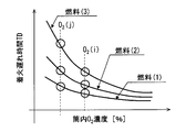
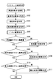
- the drawing It is the schematic of the combustion system in 1st Embodiment, Is an explanatory diagram of the ignition delay characteristics, It is a diagram for explaining the relationship between a plurality of ignition delay characteristics, a parameter representing the flammability, and the mixing amount of various components, It is a diagram showing the relationship between the characteristic line representing the change in the ignition delay characteristic caused by the in-cylinder oxygen concentration and the molecular structural species of the fuel, It is a diagram showing the relationship between the characteristic line representing the change in the ignition delay characteristic caused by the in-cylinder temperature and the molecular structural species of the fuel, It is a diagram showing the relationship between the characteristic line specified based on the ignition delay characteristic and the mixing ratio of molecular structural species, It is a flowchart which shows the procedure of a pilot control process, It is a flowchart which shows the procedure of a pilot estimation process, It is a figure for demonstrating estimation of the injection quantity
- the combustion system estimation device and control device are provided by an electronic control device (ECU 80) shown in FIG.
- the ECU 80 includes a microcomputer (microcomputer 80a), an input processing circuit and an output processing circuit (not shown), and the like.
- the microcomputer 80a includes a central processing unit (CPU) and a memory 80b (not shown).
- CPU central processing unit
- the microcomputer 80a causes the fuel injection valve 15, the fuel pump 15p, the EGR valve 17a, the temperature control valve 17d, and the supercharging pressure control device 26 included in the combustion system. Control the operation of etc.
- the combustion system and the ECU 80 are mounted on a vehicle, and the vehicle runs using the output of the internal combustion engine 10 as a drive source.
- the internal combustion engine 10 includes a cylinder block 11, a cylinder head 12, a piston 13, and the like.
- An intake valve 14 in, an exhaust valve 14 ex, a fuel injection valve 15, and an in-cylinder pressure sensor 21 are attached to the cylinder head 12.
- the fuel pump 15p pumps the fuel in the fuel tank to the common rail 15c.
- the fuel in the common rail 15c is stored in the common rail 15c while being maintained at the target pressure Ptrg.
- the common rail 15c distributes the accumulated fuel to the fuel injection valve 15 of each cylinder.
- the fuel injected from the fuel injection valve 15 is mixed with the intake air in the combustion chamber 11a to form an air-fuel mixture, and the air-fuel mixture is compressed by the piston 13 and self-ignited.
- the internal combustion engine 10 is a compression self-ignition type diesel engine, and light oil is used as fuel.
- the fuel injection by the fuel injection valve 15 includes spraying the fuel in a mist form.
- the fuel injection valve 15 is configured by accommodating an electromagnetic actuator and a valve body in the body.
- the leakage path of the back pressure chamber (not shown) is opened by the electromagnetic attractive force of the electromagnetic actuator, and the valve body is opened as the back pressure decreases, and is formed in the body.
- the nozzle hole is opened and fuel is injected from the nozzle hole.
- the valve body closes and fuel injection is stopped.
- An intake pipe 16in and an exhaust pipe 16ex are connected to the intake port 12in and the exhaust port 12ex formed in the cylinder head 12.
- An EGR pipe 17 is connected to the intake pipe 16in and the exhaust pipe 16ex, and a part of the exhaust gas (EGR gas) flows (refluxs) through the EGR pipe 17 into the intake pipe 16in.
- An EGR valve 17 a is attached to the EGR pipe 17.
- an EGR cooler 17b for cooling EGR gas, a bypass pipe 17c, and a temperature control valve 17d are attached to the upstream portion of the EGR valve 17a in the EGR pipe 17.
- the bypass pipe 17c forms a bypass channel through which EGR gas bypasses the EGR cooler 17b.
- the temperature control valve 17d adjusts the ratio of the EGR gas flowing through the EGR cooler 17b and the EGR gas flowing through the bypass flow path by adjusting the opening degree of the bypass flow path, and consequently, EGR flowing into the intake pipe 16in. Adjust the gas temperature.
- the intake air flowing into the intake port 12in includes external air (fresh air) and EGR gas flowing in from the intake pipe 16in. Therefore, adjusting the temperature of the EGR gas by the temperature control valve 17d means adjusting the temperature of the intake air flowing into the intake port 12in (intake manifold temperature).
- Combustion system has a turbocharger (not shown).
- the supercharger has a turbine attached to the exhaust pipe 16ex and a compressor attached to the intake pipe 16in.
- the above-described supercharging pressure adjusting device 26 is a device that changes the capacity of the turbine, and the ECU 80 controls the operation of the supercharging pressure adjusting device 26 so that the turbine capacity is adjusted, whereby the supercharging pressure by the compressor is adjusted. Is controlled.
- the combustion system also includes a NOx purification catalyst 31 and a DPF 32.
- the DPF 32 Diesel Particulate Filter
- the exhaust gas flowing through the exhaust pipe 16ex passes through both the NOx purification catalyst 31 and the DPF 32, and is then discharged from the downstream end of the exhaust pipe 16ex.
- the NOx purification catalyst 31 and the DPF 32 constitute an exhaust purification device.
- the ECU 80 includes detection signals from various sensors such as an in-cylinder pressure sensor 21, an oxygen concentration sensor 22, a rail pressure sensor 23, a crank angle sensor 24, an accelerator pedal sensor 25, an exhaust temperature sensor 33, an exhaust pressure sensor 34, and a catalyst temperature sensor 35. Is entered.
- the cylinder pressure sensor 21 outputs a detection signal corresponding to the pressure (cylinder pressure) in the combustion chamber 11a.
- the in-cylinder pressure sensor 21 includes a temperature detection element 21a in addition to the pressure detection element, and outputs a detection signal corresponding to the temperature (in-cylinder temperature) of the combustion chamber 11a.
- the oxygen concentration sensor 22 is attached to the intake pipe 16in, and outputs a detection signal corresponding to the oxygen concentration in the intake air.
- the intake air to be detected is a mixture of fresh air and EGR gas.
- the rail pressure sensor 23 is attached to the common rail 15c, and outputs a detection signal corresponding to the pressure of the accumulated fuel (rail pressure).
- the crank angle sensor 24 outputs a detection signal corresponding to the rotational speed (engine speed) of the crankshaft that is rotationally driven by the piston 13.
- the accelerator pedal sensor 25 outputs a detection signal corresponding to the depression amount (engine load) of the accelerator pedal that is depressed by the vehicle driver.
- the exhaust temperature sensor 33 is attached to the exhaust pipe 16ex and detects the exhaust temperature.
- the exhaust pressure sensor 34 is attached to the exhaust pipe 16ex and detects the exhaust pressure.
- the exhaust temperature sensor 33 and the exhaust pressure sensor 34 are disposed between the NOx purification catalyst 31 and the turbine in the exhaust pipe 16ex.
- the catalyst temperature sensor 35 is provided between the NOx purification catalyst 31 and the DPF 32 in the exhaust pipe 16ex, and detects the internal temperature of the NOx purification catalyst 31 by detecting the temperature of the exhaust gas that has passed through the NOx purification catalyst 31. .
- the catalyst temperature sensor 35 may be attached to the NOx purification catalyst 31.
- the ECU 80 controls the operation of the fuel injection valve 15, the fuel pump 15p, the EGR valve 17a, the temperature control valve 17d, and the supercharging pressure control device 26 based on the detection signals of the sensors 21 to 25 and 33 to 35. Thereby, the fuel injection start timing, the injection amount, the injection pressure, the EGR gas flow rate, the intake manifold temperature, and the supercharging pressure are controlled.
- the microcomputer 80a when controlling the operation of the fuel injection valve 15 functions as an injection control unit 83 that controls the fuel injection start timing, the injection amount, and the number of injection stages related to multistage injection. There are cases where injection control is performed so that the same fuel injection valve 15 injects a plurality of times (multi-stage injection) during one combustion cycle. These multiple injections include main injection with the largest injection amount, pilot injection performed at a timing before the main injection, and post injection performed at a timing after the main injection. .
- the microcomputer 80a When the operation of the fuel pump 15p is controlled, the microcomputer 80a functions as a fuel pressure control unit 84 that controls the injection pressure.
- the microcomputer 80a when controlling the operation of the EGR valve 17a functions as an EGR control unit 85 that controls the EGR gas flow rate.
- the microcomputer 80a when controlling the operation of the temperature control valve 17d functions as an intake manifold temperature control unit 87 that controls the intake manifold temperature.
- the microcomputer 80a when controlling the operation of the supercharging pressure regulating device 26 functions as a supercharging pressure control unit 86 that controls the supercharging pressure.
- the microcomputer 80a also functions as a combustion characteristic acquisition unit 81 that acquires a detection value (combustion characteristic value) of a physical quantity related to combustion.
- the combustion characteristic value according to the present embodiment is the ignition delay time TD shown in FIG.
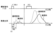
- the upper part of FIG. 2 shows a pulse signal output from the microcomputer 80a.
- Energization of the fuel injection valve 15 is controlled according to the pulse signal. Specifically, energization is started at time t1 of pulse on, and energization is continued during the pulse on period Tq. In short, the injection start timing is controlled by the pulse-on timing. Further, the injection period is controlled by the pulse-on period Tq, and consequently the injection amount is controlled.
- the ignition delay time TD can also be acquired as the ignition timing.
- the middle part of FIG. 2 shows the change in the state of fuel injection from the nozzle hole that occurs as a result of the valve body opening and closing operations according to the pulse signal. Specifically, a change in the injection amount (injection rate) of the fuel injected per unit time is shown. As shown in the drawing, there is a time lag from the time t1 when the energization starts to the time t2 when the injection is actually started. There is also a time lag from when the energization ends until the injection is actually stopped. The period Tq1 during which injection is actually performed is controlled by the pulse-on period Tq.
- FIG. 2 shows the change in the combustion state of the injected fuel in the combustion chamber 11a. Specifically, it shows a change in the amount of heat (heat generation rate) per unit time that occurs when the mixture of injected fuel and intake air undergoes self-ignition combustion. As shown in the figure, there is a time lag from the time t2 when the injection starts to the time t3 when the combustion actually starts. In the present embodiment, the time from the time point t1 when the energization starts to the time point t3 when the combustion starts is defined as the ignition delay time TD.
- the combustion characteristic acquisition unit 81 estimates the time point t3 of the combustion start based on the change in the in-cylinder pressure detected by the in-cylinder pressure sensor 21. Specifically, the time when the in-cylinder pressure suddenly increases during the period in which the crank angle rotates by a predetermined amount after the piston 13 reaches top dead center is estimated as the combustion start time (time t3). Based on this estimation result, the ignition delay time TD is calculated by the combustion characteristic acquisition unit 81. Furthermore, the combustion characteristic acquisition unit 81 acquires various states (combustion conditions) during combustion for each combustion. Specifically, in-cylinder pressure, in-cylinder temperature, intake oxygen concentration, and injection pressure are acquired as combustion conditions.
- combustion conditions are parameters representing the flammability of the fuel.
- the in-cylinder pressure and the in-cylinder temperature immediately before combustion for example, values detected at time t1 when energization of the fuel injection valve 15 is started may be used.
- the in-cylinder pressure is detected by the in-cylinder pressure sensor 21, the in-cylinder temperature is detected by the temperature detection element 21 a, the intake oxygen concentration is detected by the oxygen concentration sensor 22, and the injection pressure is detected by the rail pressure sensor 23.
- the combustion characteristic acquisition unit 81 stores the acquired ignition delay time TD in the memory 80b in association with the parameter (combustion condition) related to the combustion.
- the microcomputer 80a also functions as a mixing ratio estimation unit 82 that estimates the mixing ratio of molecular structural species contained in the fuel based on a plurality of combustion characteristic values detected under different combustion conditions. For example, the mixing amount of molecular structural species is calculated by substituting the ignition delay time TD for each different combustion condition into the determinant shown in FIG. The mixing ratio of the molecular structural species is calculated by dividing each calculated mixing amount by the total amount.
- the matrix on the left side of FIG. 3 is x rows and 1 column and is composed of x numbers. These numerical values represent the mixing amounts of various components.
- Various components are components classified according to the difference in the type of molecular structure. Types of molecular structures include straight chain paraffins, side chain paraffins, naphthenes and aromatics.
- the matrix on the left side of the right side has x rows and y columns, and is composed of numerical values such as a00. These numerical values are constants determined based on tests performed in advance.
- the matrix on the right side of the right side has y rows and 1 column and is composed of y numerical values. These numerical values are the ignition delay time TD acquired by the combustion characteristic acquisition unit 81.
- the numerical value in the first row and first column is the ignition delay time TD (i) acquired under the combustion condition i consisting of a predetermined combination of parameters
- the numerical value in the second row and first column is when the combustion condition is j.
- the obtained ignition delay time TD (j) In the combustion condition i and the combustion condition j, all parameters are set to different values.
- each of the symbols P (i), T (i), O2 (i), and Pc (i) in FIG. 3 indicates the in-cylinder pressure, the in-cylinder temperature, the intake oxygen concentration, and the injection pressure according to the combustion condition i.
- P (j), T (j), O2 (j), and Pc (j) indicate parameters related to the combustion condition j.
- Three solid lines (1), (2) and (3) in the figure are characteristic lines showing the relationship between the in-cylinder oxygen concentration and the ignition delay time TD.
- this characteristic line differs depending on the fuel. Strictly speaking, it depends on the mixing ratio of each molecular structural species contained in the fuel. Therefore, if the ignition delay time TD when the in-cylinder oxygen concentration is O2 (i) is detected, it can be inferred which molecular structural species it is. In particular, if the ignition delay time TD is compared between the case where the in-cylinder oxygen concentration is O2 (i) and the case where it is O2 (j), the mixing ratio can be estimated with higher accuracy.
- Three solid lines (1), (2) and (3) in the figure are characteristic lines showing the relationship between the in-cylinder temperature and the ignition delay time TD.
- this characteristic line differs depending on the fuel. Strictly speaking, it depends on the mixing ratio of each molecular structural species contained in the fuel. Therefore, if the ignition delay time TD when the in-cylinder temperature is B1 is detected, it can be inferred which molecular structural species it is. In particular, if the ignition delay time TD is compared between the case where the in-cylinder temperature is T (i) and the case where the cylinder temperature is T (j), the mixing ratio can be estimated with higher accuracy.
- the molecular structural species having a high influence on the characteristic line related to the in-cylinder oxygen concentration are different from the molecular structural species having a high influence on the characteristic line related to the in-cylinder temperature (see FIG. 5).
- the molecular structural species having a high influence on the characteristic lines related to each of the plurality of combustion conditions are different. Therefore, based on the combination of the ignition delay times TD obtained by setting a plurality of parameters (combustion conditions) to different values, it is possible to estimate with high accuracy which molecular structural species are mixed as shown in FIG. 6, for example.
- the molecular structural species B is a molecular structural species having a high influence on the characteristic line (second characteristic line) related to the in-cylinder temperature (second parameter)
- the molecular structural species C is a characteristic line related to the third parameter. It is a molecular structural species having a high influence on (third characteristic line). It can be said that the larger the change in the ignition delay time TD with respect to the change in the first parameter, the more molecular structural species A are mixed.
- the mixing ratio of the molecular structural species A, B, and C can be estimated for each of the different fuels (1), (2), and (3).
- the combustion characteristic acquisition unit 81 estimates the combustion start time t3 based on the detection value of the in-cylinder pressure sensor 21, and calculates an ignition delay time TD related to pilot injection.
- the ignition delay time TD is stored in the memory 80b in association with a plurality of parameters (combustion conditions).
- the ignition delay time TD (i) shown in FIG. 3 represents the ignition delay time TD acquired when the P (i), T (i), O2 (i), and Pc (i) regions are combined.
- the ignition delay time TD (j) represents the ignition delay time TD obtained when the P (j), T (j), O2 (j), and Pc (j) regions are combined.
- Reset the mixing amount value For example, when the operation of the internal combustion engine 10 is stopped, the reset is performed when an increase in the remaining amount of fuel is detected by a sensor that detects the remaining amount of fuel in the fuel tank.
- the combustion characteristic acquisition unit 81 calculates the mixing amount for each molecular structural species by substituting the ignition delay time TD into the determinant of FIG.
- the number of columns of the matrix representing the constant is changed according to the number of samplings, that is, the number of rows of the matrix on the right side of the determinant.
- a preset nominal value is substituted into the matrix of the ignition delay time TD. Based on the calculated mixing amount for each molecular structural species, the mixing ratio for each molecular structural species is calculated.
- the microcomputer 80a also functions as the injection control unit 83, the fuel pressure control unit 84, the EGR control unit 85, the supercharging pressure control unit 86, and the intake manifold temperature control unit 87.
- These control means set a target value based on the engine speed, the engine load, the engine coolant temperature, and the like, and perform feedback control so that the control target becomes the target value. Alternatively, open control is performed with contents corresponding to the target value.
- the injection control unit 83 controls the injection start timing, the injection amount, and the number of injection stages (injection control) by setting the pulse signal of FIG. 2 so that the injection start timing, the injection amount, and the injection stage number become target values.
- the number of injection stages is the number of injections related to the multistage injection described above. Specifically, the on-time (energization time) and pulse-on rising time (energization start time) of the pulse signal corresponding to the target value are stored in advance on the map. Then, the energization time and energization start time corresponding to the target value are acquired from the map, and the pulse signal is set.
- output torque values obtained by injection, emission state values such as NOx amount and PM amount are stored.
- the target value is corrected based on the value stored as described above.
- feedback control is performed by correcting the target value so that the deviation between the actual output torque and emission state value and the desired output torque and emission state value becomes zero.
- the fuel pressure control unit 84 controls the operation of a metering valve that controls the flow rate of the fuel sucked into the fuel pump 15p. Specifically, the operation of the metering valve is feedback-controlled based on the deviation between the actual rail pressure detected by the rail pressure sensor 23 and the target pressure Ptrg (target value). As a result, the amount of discharge per unit time by the fuel pump 15p is controlled, and control (fuel pressure control) is performed so that the actual rail pressure becomes the target value.
- the EGR control unit 85 sets a target value for the EGR amount based on the engine speed, the engine load, and the like. Based on this target value, the valve opening of the EGR valve 17a is controlled (EGR control) to control the EGR amount.
- the supercharging pressure control unit 86 sets a target value for the supercharging pressure based on the engine speed, the engine load, and the like. Based on this target value, the operation of the supercharging pressure regulating device 26 is controlled (supercharging pressure control) to control the supercharging pressure.
- the intake manifold temperature control unit 87 sets a target value of the intake manifold temperature based on the outside air temperature, the engine speed, the engine load, and the like. Based on this target value, the valve opening of the temperature control valve 17d is controlled (intake manifold temperature control) to control the intake manifold temperature.
- the microcomputer 80a functions as the injection control unit 83 to execute pilot control processing for controlling pilot injection.
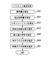
- the pilot control process will be described with reference to the flowchart of FIG. This process is repeatedly executed at a predetermined cycle during the operation period of the internal combustion engine 10.
- step S101 of FIG. 7 the mixing ratio (actual mixing ratio) estimated by the mixing ratio estimation unit 82 is acquired. That is, the mixing ratio for each of the molecular structural species shown on the left side of FIG. 3 is acquired.
- the reference value of the mixing ratio (reference mixing ratio) for each molecular structural species is preset and stored in the memory 80b. These reference mixing ratios are set in view of the fuel distributed in the country or region where the vehicle is used.
- step S1010 grouped molecular structural species such as linear paraffins, side chain paraffins, naphthenes, and aromatics are estimated. Note that step S101 corresponds to the mixture acquisition unit.
- the reference mixture ratio is read from the memory 80b and acquired.
- the injection condition for pilot injection is acquired.
- the injection condition include a rail pressure that is a fuel pressure in the common rail 15c, a target injection amount that is a target value of the injection amount, an energization period to the fuel injection valve 15, a needle lift amount of the fuel injection valve 15, and the like.
- the rail pressure is an injection pressure under combustion conditions.
- an in-cylinder environmental condition when pilot injection is performed is acquired.
- the in-cylinder environmental conditions include in-cylinder temperature that is the temperature of the combustion chamber 11a, in-cylinder oxygen concentration that is the oxygen concentration of the combustion chamber 11a, in-cylinder flow velocity that is the flow rate of the air-fuel mixture in the combustion chamber 11a, and the like. .
- the in-cylinder temperature is also included in the combustion conditions.
- the in-cylinder oxygen concentration is acquired based on the intake oxygen concentration included in the combustion conditions.
- pilot estimation processing is performed.
- the pilot estimation process will be described with reference to the flowchart of FIG.
- combustion of fuel by pilot injection is referred to as pilot combustion, and this state is referred to as a pilot combustion state.
- the pilot combustion state differs if the mixing ratio of the molecular structural species contained in the fuel is different.
- the state of pilot injection or pilot combustion is estimated, and the state of pilot combustion gas generated by pilot combustion in the combustion chamber 11a is estimated based on the estimation result.
- the injection state of the pilot injection is estimated based on the actual mixing ratio of the molecular structural species acquired in step S101.
- the injection parameters indicating the injection state of pilot injection include six injection parameters, lower heating value, penetration, diffusion state, ignition delay characteristic, and OH radical distribution.
- the values of the injection parameters corresponding to the in-cylinder environment are acquired in advance by a test or the like, and these acquired data are stored as reference data in the memory 80b.
- the value of each injection parameter is estimated by comparing with reference data.
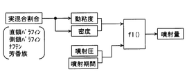
- step S201 the injection amount of pilot injection is estimated based on the actual mixing ratio.
- the kinematic viscosity and density of the general properties of the fuel are estimated based on the actual mixing ratio, and predetermined for the kinematic viscosity and density and the injection pressure and injection period of the injection conditions. Is used to estimate the injection amount.
- kinematic viscosity and density are part of the fuel characteristics that are chemically affected
- injection pressure and injection period are part of the usage and environmental conditions that are physically affected.
- an estimation model such as a multiple regression model or a map may be used instead of the function f1 ().
- a pulse-on period Tq may be used as the injection period.
- Step S201 corresponds to the injection amount estimation unit.
- step S202 the lower heating value of the actual fuel is estimated based on the actual mixing ratio.
- the average carbon number and average hydrogen number of the actual fuel are estimated based on the actual mixing ratio, and a predetermined function f2 () is used for these average carbon number and average hydrogen number.
- the lower heating value is estimated.
- the average carbon number and the average hydrogen number are determined by the fuel characteristics that are chemically affected.
- an estimation model or a map may be used instead of the function f2 ().
- Step S202 corresponds to a heat generation amount estimation unit.
- step S203 fuel penetration by pilot injection is estimated based on the actual mixing ratio.
- the penetration is a penetrating force that indicates the force by which the fuel injected from the fuel injection valve 15 goes straight through the combustion chamber 11a.
- the penetration tends to decrease as the amount of evaporation in the combustion chamber 11a increases. Therefore, the fuel penetration is estimated by estimating the volatility of the fuel based on a plurality of distillation properties.
- Step S203 corresponds to the penetrating force estimation unit.
- the distillation property T50 at which 50% evaporates is the same between the reference fuel and the actual fuel.
- the distillation properties T10 and T90 may differ between the reference fuel and the actual fuel.
- the estimation accuracy is improved by estimating the fuel penetration based on a plurality of distillation properties.
- the distillation property T50 itself may greatly differ between the reference fuel and the actual fuel. For this reason, the precision of penetration can also be raised by estimating and comparing the distillation property T50 which is an average distillation characteristic from the average carbon number etc. for every fuel.
- the momentum increases as the mass of the particles increases, and the penetration tends to increase.
- the fuel density in the spray increases and the mass of the particles tends to increase.
- the shearing force of the fuel with respect to the air, the fuel injection speed in the nozzle hole, the density of the fuel, and the like are easily affected by kinematic viscosity and viscosity.
- the shearing force of the fuel is easily affected by the in-cylinder pressure, and the higher the in-cylinder pressure, the higher the shearing force of the fuel.
- the higher the volatility the more the particles lose mass and the less momentum.
- a fuel having a low temperature from the initial boiling point to T50 of the distillation property is relatively easy to vaporize and the penetration tends to be small.
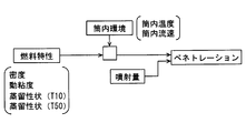
- step S203 the fuel characteristics including density, kinematic viscosity and a plurality of distillation properties, the in-cylinder environment including in-cylinder temperature and in-cylinder flow velocity, and the injection amount estimated in step S201 ,
- the penetration depends on the in-cylinder environmental condition and the injection condition, and can be estimated by a mathematical expression as shown in FIG. In this numerical formula, penetrations P1, P2, P3... According to the in-cylinder environmental conditions and the injection conditions are estimated based on predetermined constant b and fuel characteristics such as kinematic viscosity.
- the constant b is x rows and y columns, and is a matrix having numerical values b00... BXY, for example.
- the penetration it is also possible to estimate the penetration by estimating the provisional penetration based on the actual mixing ratio and correcting the provisional penetration with the injection amount. Further, the distillation property is estimated based on the actual mixing ratio contained in the fuel. For this reason, in addition to general properties such as density, kinematic viscosity and distillation properties, the fuel characteristics include elements of the actual mixing ratio.
- step S204 the diffusion state of fuel by pilot injection is estimated based on the actual mixing ratio.
- the diffusion state is a degree of diffusion indicating how much the injected fuel diffuses.
- the injected fuel is more easily diffused as the amount of evaporation in the combustion chamber 11a increases. Therefore, as in the case of penetration, the diffusion state of the fuel is estimated by estimating the volatility of combustion based on a plurality of distillation properties.
- Step S204 corresponds to the diffusion estimation unit.
- the diffusion state depends on the in-cylinder environmental condition and the injection condition, and can be estimated by a mathematical expression as shown in FIG. In this mathematical formula, the diffusion states D1, D2, D3... According to the in-cylinder environmental conditions and the injection conditions are estimated based on predetermined constant c and fuel characteristics such as kinematic viscosity.
- the constant c is x rows and y columns, and is a matrix having a numerical value of c00... CXY, for example.
- diffusion state can be calculated using a well-known mathematical expression indicating the spray momentum theory.
- the ignition delay characteristic of the actual fuel is estimated based on the actual mixing ratio.
- the ignition delay characteristic is a characteristic indicating the ease of ignition. For example, when the in-cylinder environment is in a state of prompting ignition, the ignition delay characteristic is expressed by the time required for starting the ignition of fuel. Examples of the state in which the in-cylinder environment promotes ignition include a state in which the in-cylinder temperature and the in-cylinder pressure are sufficiently high for the occurrence of ignition. Step S205 corresponds to the ignition delay estimation unit.
- the OH radical distribution is estimated based on the injection amount, lower heating value, penetration, diffusion state and actual mixing ratio, in-cylinder temperature and in-cylinder oxygen concentration.
- the OH radical distribution indicates the generation state of OH radicals in the combustion chamber 11a, and examples thereof include the density, amount, and position of OH radicals.
- Examples of the position of the OH radical include the position of the center of gravity of the region where the OH radical is generated and the initial generation position.
- the OH radical distribution is estimated by using a predetermined function f3 () for the injection amount, the lower heating value, the penetration, the diffusion state, and the actual mixing ratio.
- f3 () includes the physical conditions relating to the atmospheric field such as the in-cylinder temperature and the in-cylinder oxygen concentration described above. As will be described later, for pilot injection, estimating the OH radical distribution will estimate the amount, density, and position of the distribution of combustible molecules such as ketones and aldehydes.
- Step S206 corresponds to the OH radical estimation unit. Further, the OH radical distribution may be estimated based on the injection pressure in addition to the actual mixing ratio, the in-cylinder temperature, and the in-cylinder oxygen concentration.
- pilot injection performed while the in-cylinder temperature is rising pilot injection performed while the in-cylinder temperature is rising
- main injection, after-injection, and post-injection performed while the in-cylinder temperature is decreasing are performed in this order.
- the in-cylinder oxygen concentration has the largest timing at which pilot injection is performed, decreases in the order of main injection and after injection, and has the minimum timing at which post injection is performed.
- the in-cylinder temperature is a low temperature at which the timing at which pilot injection is performed after the start of intake is the lowest, and rises to a sufficiently high temperature at the timing at which main injection and after injection are performed. Thereafter, the in-cylinder temperature decreases as the cylinder volume increases in the expansion stroke of the piston, but the intermediate temperature is higher at the timing when the post injection is performed than when the pilot injection is performed.
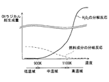
- the low temperature region is 900K or less
- the intermediate temperature region is 900K to 1100K
- the high temperature region is 1100K or more.
- OH radicals are generated as fuel is injected, so that chemical combustion is started by oxidation of combustible molecules such as ketones and aldehydes.
- Reactions that generate OH radicals include a decomposition reaction in which hydrogen peroxide H 2 O 2 generated from an inactive HO 2 radical and an alkene is decomposed into OH radicals, oxygen is added to the hydrocarbon, and flammable molecules are
- a chain branching reaction that repeats generation and consumption of OH radicals in the process of generation.
- the chain branching reaction the amount of OH radicals produced and consumed are almost the same, and estimating the component that contributes to OH radicals is synonymous with estimating the amount of combustible molecules produced.
- Each molecular structural species of the fuel includes a generated molecule that easily generates OH radicals in the course of the chain branching reaction and an inhibitor molecule that does not easily generate OH radicals.
- the generated molecules include straight-chain paraffins, and the inhibitor molecules include aromatics.
- the ease of ignition differs depending on the density distribution between the generated molecules and the inhibitor molecules in any case, not only in the chain branching reaction.
- the ignition timing changes according to the generation state of OH radicals and the fluid disturbance inside and outside the spray.
- the density distribution of the generated molecule and the inhibitor molecule affects the generation position along the time series of the OH radical distribution generated by the chain branching reaction, and the generation mode of the chain branching reaction is correlated with the fuel component. It can be said that.
- the ease of ignition associated with fuel injection varies depending on which temperature range the in-cylinder temperature is at. As shown in FIG. 17, in the low temperature range where the in-cylinder temperature is 900K or less, H 2 O 2 is hardly decomposed, and the amount of OH radicals generated by the decomposition reaction of H 2 O 2 is very small.
- a chain branching reaction is likely to occur due to a component that can extract hydrogen by intramolecular isomerization and have a low strain energy, and the amount of OH radicals involved in this chain branching reaction is compared. It is becoming more and more popular. In this case, a chain branching reaction is likely to occur due to the presence of many generated molecules, and the decomposition reaction of H 2 O 2 is unlikely to occur.
- the inventors have obtained the knowledge that the dependence of the ignition timing on the fuel component is high in the low temperature range where the pilot injection is performed.
- OH radical generation and ⁇ -cleavage accompanying H 2 O 2 decomposition at high temperature may be forced on combustible molecules such as ketones and aldehydes having 1 to 3 carbon atoms (C1 to C3).
- ignition delay is likely to occur.
- H 2 O 2 is easily decomposed, but the amount of OH radicals generated by the decomposition reaction of H 2 O 2 increases rapidly as the temperature rises. Not done.
- the amount of OH radicals generated by the decomposition reaction of H 2 O 2 is larger than that of OH radicals generated by a chain branching reaction with fuel components.
- the number of molecules having 1 to 3 carbon atoms increases before the formation of a structure having a small strain energy at which the chain branching reaction occurs, and the chain branching reaction gradually decreases.
- the inventors have determined that the ignition timing in the intermediate temperature range where the post-injection is performed, the ignition delay depending on the generated molecules as the fuel component causing the chain branching reaction, and the fuel such as generated molecules. It was found that it is necessary to consider the ignition delay due to the decomposition reaction of H 2 O 2 having no sensitivity to the components. For this reason, in the intermediate temperature range, the dependence of the ignition timing on the fuel component is lower than in the low temperature range where pilot injection is performed, and depending on the actual mixing ratio, the post injection is less likely to cause an ignition delay than the pilot injection. Become.
- the combustion state of fuel by pilot injection is estimated using the injection parameters estimated in steps S201 to S206.
- the reference fuel the values of the respective combustion parameters corresponding to the in-cylinder environment are acquired in advance by a test or the like, and these acquired data are stored as reference data in the memory 80b in the same manner as the injection parameters.
- the value of each combustion parameter is estimated by comparing with reference data.
- step S207 the amount of combustion by pilot injection is estimated.
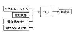
- the combustion amount is calculated using the mathematical formula shown in FIG. In this equation, Qburn is the combustion amount, ⁇ is the combustion rate, ⁇ ⁇ Qinj is the injection amount, A is the lower heating value.
- the combustion rate ⁇ is determined by the penetration estimated in step S203, the diffusion state estimated in step S204, the OH radical distribution estimated in step S205, and the ignition delay estimated in step S205. It is estimated by using a predetermined function f4 () with respect to the characteristics.
- the spray volume of pilot injection is estimated using a penetration and a diffusion state. Step S207 corresponds to the combustion amount estimation unit.
- step S208 the combustion region by pilot injection is estimated.
- the combustion region is estimated by using a predetermined function, map, model or the like with respect to the injection amount, penetration, diffusion state, ignition timing, and OH radical distribution.
- Step S208 corresponds to the region estimation unit.
- step S209 the ignition timing by pilot injection is estimated.
- injection amount injection amount
- diffusion state diffusion state
- ignition delay characteristic OH radical
- the ignition timing is estimated by using a predetermined function, map, model or the like for the injection amount, the diffusion state, the ignition delay characteristic, and the OH radical.
- Step S209 corresponds to the time estimation unit.
- step S210 the state of the combustion gas generated by the pilot combustion is estimated using each combustion parameter estimated in steps S206 to S208.
- the temperature of the combustion gas is estimated based on the combustion amount
- the position of the combustion gas is estimated based on the combustion region
- the generation timing of the combustion gas is estimated based on the ignition timing.
- the ignition delay time TD2 as the ignition timing of the actual fuel is longer than the ignition delay time TD1 of the reference fuel, the generation timing of the combustion gas by the pilot combustion is the reference for the actual fuel. It will be later than fuel. In this case, since the timing at which the temperature of the combustion gas reaches an appropriate temperature when ignition by main injection occurs is delayed, there is a concern that the stability of ignition by main injection may be reduced.
- pilot injection when the actual fuel ignition delay time TD1 is larger than the reference fuel ignition delay time TD2, it is expected that the ignition delay time of the main injection performed by the actual fuel also increases. In this case, there is a possibility that the ignition accompanying the main injection is not properly performed and misfire occurs due to an increase in the ignition delay time in both the pilot injection and the main injection.
- the local temperature near the nozzle hole rises when the injected fuel is not diffused, so that an environment in which the main spray is easy to ignite can be created.
- the fuel when fuel that does not diffuse excessively in the pilot combustion region is used, the fuel contains many molecular structural species that are heavy and have high kinematic viscosity, and the pilot combustion region is located near the nozzle hole. Even if it is done, it is thought that the ignitability of the main spray is lowered.
- step S106 the combustion amount of the reference fuel is read from the memory 80b, and the “deviation” between the combustion amount of the reference fuel and the combustion amount of the actual fuel is calculated as a difference. It is determined whether or not the difference is smaller than a predetermined reference amount.
- the difference in this case is the absolute value of the difference between the combustion amount of the reference fuel and the combustion amount of the actual fuel.
- the target value of the combustion parameter such as the amount of combustion by pilot injection is set according to the operating state of the internal combustion engine 10, and the criterion for the difference is set according to the target value of the combustion parameter. For example, when the amount of depression of the accelerator pedal by the driver increases, the target value of the combustion parameter is set so as to increase the output of the internal combustion engine 10.
- step S107 the combustion amount is adjusted so that the difference is smaller than the reference amount.
- the combustion amount is adjusted so that the difference is smaller than the reference amount.
- the increasing process include a process for increasing the injection amount, a process for increasing the injection pressure, a process for shifting the injection timing to the top dead center TDC side of the piston 13, and a process for decreasing the EGR amount.
- the reduction process include a process for reducing the injection amount, a process for reducing the injection pressure, a process for shifting the injection timing toward the dead center BDC side of the piston 13, and a process for increasing the EGR amount.
- a target value for making the difference in the combustion amount smaller than the reference amount is set based on the actual mixing ratio.
- the provisional target value is acquired based on the reference mixing ratio, and the provisional target value is corrected using the actual mixing ratio, thereby calculating the target value.
- the target value of the injection amount is acquired based on the difference between the combustion amount and the reference amount using the reference mixing ratio, and the provisional target value is obtained as the actual mixing ratio.
- the target value is calculated by correcting using. This suppresses the fact that the injection amount is insufficient due to the actual mixing ratio despite the processing for increasing the injection amount.
- step S108 If the difference in the combustion amount is smaller than the reference amount, the process proceeds to step S108 as it is because it is not necessary to adjust the combustion amount.
- step S108 the reference fuel combustion region is read from the memory 80b, the "deviation" between the reference fuel combustion region and the actual fuel combustion region is calculated as a difference, and is this difference smaller than a predetermined reference distance? Determine whether or not.
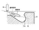
- the difference in this case is the absolute value of the separation distance between the tip of the reference fuel combustion region and the tip of the actual fuel combustion region in the direction in which the nozzle hole of the fuel injection valve 15 extends.
- step S109 adjustment processing of the combustion region is performed so that the difference is smaller than the reference distance.
- an approach process for bringing the front end of the combustion region of the actual fuel closer to the injection hole is performed.
- a separation process is performed to move the tip of the actual fuel combustion region away from the nozzle hole.
- Examples of the approaching process include a process of increasing the number of injection stages of pilot injection and a process of shifting the injection timing to the TDC side.
- Examples of the separation processing include processing for reducing the number of pilot injection stages and processing for shifting the injection timing to the BDC side.
- a target value for making the difference in the combustion region smaller than the reference distance is set based on the actual mixing ratio.
- the provisional target value is acquired based on the reference mixing ratio, and the target value is calculated by correcting the provisional target value using the actual mixing ratio.
- step S110 If the difference in the combustion area is smaller than the reference distance, the process proceeds to step S110 as it is, assuming that the adjustment process of the combustion area is not necessary.
- step S110 the ignition timing of the reference fuel is read from the memory 80b, and a “deviation” between the ignition timing of the reference fuel and the ignition timing of the actual fuel is calculated as a difference. Is this difference smaller than a predetermined reference time? Determine whether or not.
- the difference in this case is an absolute value of the difference between the ignition timing of the reference fuel and the ignition timing of the actual fuel.
- the process proceeds to step S111, and the ignition timing is adjusted so that the difference is smaller than the reference time.
- the early processing is performed to advance the ignition timing.
- the delay process is performed. Examples of the early processing include processing for bringing the injection timing closer to the TDC side and processing for increasing the number of injection stages, and examples of the delay processing include processing for moving the injection timing away from the TDC side and processing for reducing the number of injection stages.
- a target value for making the ignition timing difference smaller than the reference time is set based on the actual mixing ratio.
- the provisional target value is acquired based on the reference mixing ratio, and the target value is calculated by correcting the provisional target value using the actual mixing ratio.
- Steps S107, S109, and S111 correspond to the combustion control unit.
- the first embodiment it is possible to grasp the state of pilot combustion gas by pilot injection by estimating three combustion parameters of the combustion amount, the combustion region, and the ignition timing for pilot combustion by pilot injection. That is, it is possible to grasp the ease of fuel ignition by main injection.
- the inventors have also found that the relationship between the three combustion parameters is not regular with respect to the mixing ratio of the molecular structural species contained in the fuel.
- all of the three combustion parameters are estimated based on the actual mixing ratio, it is possible to appropriately ensure the estimation accuracy of the pilot combustion. For this reason, even when an unexpected fuel is used, the state of main combustion by main injection can be optimized by appropriately managing each of these combustion parameters.
- three combustion parameters are estimated using the OH radical distribution in addition to the five injection parameters of the injection amount, the lower heating value, the penetration, the diffusion state, and the ignition delay characteristic.
- the injection parameter and the OH radical are estimated using the actual mixing ratio
- the actual mixing ratio is indirectly used for estimating the combustion parameter.
- the dependence of the estimation result on the function, the map, and the model is reduced compared to the case where the combustion parameter is directly estimated using the function, the map, and the model with respect to the actual mixing ratio, It is possible to reduce the difficulty of creating functions, maps, and models. For this reason, the estimation precision of a combustion parameter can be improved.
- the five injection parameters and the OH radical distribution accompanying the injection are individually estimated based on the actual mixing ratio. For this reason, even if the influence degree of the actual mixing ratio differs for each injection parameter, the influence degree of the actual mixing ratio is obtained by using all of the five injection parameters and the OH radical distribution accompanying the injection when estimating the combustion amount.
- the combustion amount can be estimated in consideration of the difference.
- the inventors have obtained the knowledge that the five injection parameters and the OH radical distribution accompanying the injection have a correlation according to the actual mixing ratio through tests and simulations. Even in this case, the estimation accuracy of the combustion amount can be improved by using all of the five injection parameters and the OH radical distribution accompanying the injection.
- the estimation accuracy of the combustion amount can be improved.
- the estimation accuracy is lowered by increasing the number of injection parameters used for estimating the combustion region.
- the estimation of the ignition timing uses four of the five injection parameters and the OH radical distribution accompanying the injection: the injection amount, the diffusion state, the ignition delay characteristic, and the OH radical distribution.
- the processing burden at the time of estimation can be reduced.
- estimating the ignition timing not using low calorific value and penetration, which have low influence on the ignition timing, do not include the effect of the actual mixing ratio on the estimation of the low calorific value and penetration in the estimation result of the combustion region become. For this reason, it can be avoided that the estimation accuracy is lowered by increasing the number of injection parameters used for estimating the ignition timing.
- the OH radical distribution is estimated based on the actual mixing ratio, it is possible to grasp the distribution of combustible molecules generated in the course of the chain branching reaction in a low temperature range where pilot injection is performed. For this reason, even if the time required from the chain branching reaction to ignition varies depending on the fuel component, the ignition timing can be properly estimated. Moreover, since the OH radical distribution is estimated based on the four injection parameters of injection amount, lower heating value, penetration, and diffusion state in addition to the actual mixing ratio, the amount, density, and position of OH radicals are used as the distribution. Can be estimated. For this reason, the estimation precision of OH radical distribution can be improved.
- the pilot molecules are considered in consideration of the distribution of the generated molecules that cause the chain branching reaction in the low temperature range where the pilot injection is performed.
- the state of combustion gas by injection can be grasped.
- fuel ignition is easier than chain branching reaction than H 2 O 2 decomposition reaction. easily influenced.
- it is effective to use the OH radical distribution to estimate the three combustion parameters for the pilot injection.
- the combustion amount, the combustion region, and the ignition timing are adjusted even though these adjustment processes are performed. Occurrence of a situation in which the deviation is not included in the reference amount, the reference distance, or the reference time can be suppressed. For this reason, in the configuration in which the estimation accuracy of the combustion amount, the combustion region, and the ignition timing is increased by using the actual mixing ratio, the high estimation accuracy can be effectively used for the control of the internal combustion engine 10.
- the state of the combustion gas is estimated based on the combustion parameters such as the combustion amount for the pilot injection, but in the second embodiment, the combustion gas state is determined based on the ignition delay characteristic and the OH radical distribution. The state is estimated.
- the pilot control process of this embodiment is demonstrated referring the flowchart of FIG. 22, FIG.
- steps S301 to S305 the same processing as in steps S101 to S105 of the first embodiment is performed.
- the pilot estimation process in step S305 the estimation of the three combustion parameters of the combustion amount, the combustion region, and the ignition timing is not performed.
- steps S401 to S406 the same processing as in steps S201 to S206 of the first embodiment is performed.
- the process proceeds to step S407, and the state of the combustion gas by the pilot combustion is estimated as in step S210 of the first embodiment.
- the ignition delay characteristic and the OH radical distribution are used for estimating the combustion gas, instead of using the three combustion parameters.
- the temperature and position of the pilot combustion gas are estimated based on the OH radical distribution
- the generation timing of the combustion gas is estimated based on both the OH radical distribution and the ignition delay characteristic.
- the OH radical distribution includes information such as the amount, density, and position of the generated molecules that cause the chain branching reaction.
- the position of the pilot combustion gas can be estimated from the initial generation position of OH radicals, diffusivity, and penetration. Furthermore, if the actual fuel has a characteristic that an ignition delay is likely to occur, the generation timing of the combustion gas tends to be delayed.
- the high density of the fuel means that the ratio of the number of hydrogens to the number of carbons is a real fuel having a high ratio of aromatics with a low HC ratio, and the ratio of aromatics is high. It is considered to be real fuel with low characteristics. That is, when the density of the actual fuel is high, the pilot combustion gas temperature tends to be high when the same fuel amount (fuel volume) is injected as the pilot injection amount, and on the other hand, there are many aromatics, so pilot combustion The ignition timing of will be extremely late.
- step S306 it is determined in step S306 whether or not the OH radical distribution of the actual fuel is appropriate.
- the reference fuel OH radical distribution data corresponding to the in-cylinder environment is acquired in advance by a test or the like, and this data is stored in the memory 80b.
- the OH radical distribution of the reference fuel is read from the memory 80b, and the “deviation” between the OH radical distribution of the reference fuel and the OH radical distribution of the actual fuel is calculated as a difference, and this difference is included in the allowable range. It is determined whether or not. This difference is calculated for the amount, density, and position of OH radicals. If the difference is not included in the allowable range, the OH radical distribution of the actual fuel is not appropriate, and the process proceeds to step S307.
- step S307 the OH radical distribution is adjusted so that the OH radical distribution is appropriate. For example, processing for adjusting the injection amount and EGR amount is performed for the amount of OH radicals, processing for shifting the injection pressure is performed for density, and processing for shifting the injection timing is performed for position.
- a target value for setting the difference of the OH radical distribution within the allowable range is set based on the actual mixing ratio.
- step S308 the ignition delay characteristic of the reference fuel is read from the memory 80b, and the “deviation” between the ignition delay characteristic of the reference fuel and the ignition delay characteristic of the actual fuel is calculated as a difference, and this difference is included in the allowable range. It is determined whether or not. This difference is calculated for the time required for ignition when fuel is present in the in-cylinder environment. When the difference is not included in the allowable range, it is determined that the ignition delay characteristic of the actual fuel is not appropriate, and the process proceeds to step S309.
- an ignition delay time adjustment process is performed so that the difference in the time required until ignition is included in the allowable range. For example, if the time required until ignition is off from the allowable range to the long side, adjustment processing is performed so that the ignition delay time is short, and if the required time is outside the allowable range, Adjustment processing is performed so that the ignition delay time becomes longer. Examples of the adjustment process for the ignition delay time include a process for adjusting the injection timing and the number of injection stages. In the adjustment process of the ignition delay time, a target value is set based on the actual mixing ratio so that the difference in the required time until the ignition is included in the allowable range.
- the state of the combustion gas generated by the pilot combustion can be grasped. Since the combustion of fuel by pilot injection largely depends on the generation of OH radicals by chain branching reaction, the temperature and position of the combustion gas by pilot combustion can be estimated by estimating the OH radical distribution. In addition, since the timing at which combustion gas is generated depends on the ease of ignition of the actual fuel in addition to the chain branching reaction, the generation timing of combustion gas by pilot combustion is estimated by estimating the ignition delay characteristics of the actual fuel. Can be estimated. Therefore, the state of the main combustion generated by the main injection can be optimized by managing the pilot injection.
- the mixing ratio estimation unit 82 does not estimate the mixing ratio of molecular structural species based on a plurality of combustion characteristic values, but detects the general properties of the fuel with a sensor, and the mixing ratio based on the detection result May be estimated.
- Specific examples of the general properties include fuel density, kinematic viscosity, distillation temperature, and the like.
- the mixing ratio may be estimated based on both the estimation result by the mixing ratio estimation unit 82 and the detection result of the sensor. For example, the mixing ratio estimated based on one of the estimation result and the detection result may be corrected based on the other. Moreover, you may estimate by a different method according to molecular structural species. For example, the mixing ratio of the first molecular structural species is estimated based on the estimation result by the mixing ratio estimation unit 82, and the mixing ratio of the second molecular structural species is estimated based on the detection result of the sensor. .
- the mixing ratio of components such as hydrogen, carbon, sulfur, nitrogen, and oxygen included in the fuel may be estimated instead of estimating the mixing ratio of the molecular structural species included in the fuel.
- the average carbon number, average hydrogen number, HC ratio, etc. can be mentioned as the mixing ratio for hydrogen and carbon.
- an injection parameter such as an injection amount and a combustion parameter such as a combustion amount are estimated based on the mixing ratio of various components. In this case, even if the components contained in the actual fuel are different or the mixing ratios of the components are different, the combustion state by the pilot injection can be properly estimated.
- the fuel component such as the average carbon number can also be referred to as an intermediate parameter.
- the control process of the combustion system is not performed based on the OH radical distribution and the ignition delay characteristic as in the second embodiment, but based on the injection parameters different from the OH radical distribution and the ignition delay characteristic. It may be done. For example, a “deviation” between the actual fuel injection amount and the reference fuel injection amount is calculated as a difference, and the injection amount adjustment processing is performed based on this difference. Even in this case, it can be avoided that the control accuracy of the combustion system is excessively lowered due to the correlation between the six injection parameters.
- the adjustment process in step S107 in the first embodiment and the adjustment process in step 307 in the second embodiment are not performed based on the actual mixing ratio, but are related to the actual mixing ratio. It may be done without.
- the target injection amount and the like are set regardless of the actual mixing ratio in order to adjust the combustion amount.
- the configuration is as follows.
- a combustion parameter such as a combustion amount may be estimated using at least one of six injection parameters such as an injection amount.
- the combustion amount is estimated using only the injection amount. Even in this case, a certain degree of estimation accuracy can be ensured in estimating the combustion amount due to the correlation between the five injection parameters.
- the OH radical distribution instead of using the four injection parameters of the injection amount, the lower heating value, the penetration, and the diffusion state, at least one of these four injection parameters may be used. Good. Moreover, it is not necessary to use all these four injection parameters. In any case, at least the actual mixing ratio may be used when estimating the OH radical distribution.
- At least one of the in-cylinder temperature, the in-cylinder oxygen concentration, and the injection pressure may be used in addition to the actual mixing ratio.
- the amount of OH radicals generated by the decomposition reaction of H 2 O 2 is relatively small, it is possible to grasp the amount of OH radicals generated and the time required for the generation.
- the estimation accuracy of the combustion gas state can be improved.
- the higher heating value may be used as the injection parameter.
- a heat generation amount including both a low heat generation amount and a high heat generation amount may be used as the injection parameter.
- the injection parameter such as the injection amount and the combustion parameter such as the combustion amount for each of the actual mixing ratio and the reference mixing ratio.
- the difference between the actual mixing ratio and the reference mixing ratio may be calculated, and the difference between the injection parameter and the combustion parameter may be estimated based on this difference.
- the “deviation” between the combustion state of the reference fuel and the combustion state of the actual fuel is directly estimated.
- the combustion parameter such as the combustion amount may be estimated without using the injection parameter such as the injection amount.
- the combustion amount is not estimated based on the injection parameter, but is estimated based on the detection signal of the in-cylinder pressure sensor 21 and the actual mixing ratio. Even in this case, the actual fuel mixing ratio can be reflected in the estimation of the combustion amount.
- the control process for the main injection may be performed using the estimation result of the injection parameter and the combustion parameter for the pilot injection.
- the control process for the main injection may be performed using the estimation result of the injection parameter and the combustion parameter for the pilot injection.
- the control process for the main injection may be performed using the estimation result of the injection parameter and the combustion parameter for the pilot injection.
- pilot combustion when the ignition timing of the actual fuel is later than the ignition timing of the reference fuel by a time exceeding the reference time, processing is performed so that ignition by main injection is likely to occur. Examples of this process include a process for increasing the number of injection stages and a process for increasing the injection pressure.
- an amount obtained by adjusting the combustion amount or the like may be stored as a correction amount, and the correction amount may be used for adjustment of the combustion parameter or the injection parameter.
- the amount of adjustment of the injection amount, the injection pressure, and the injection timing is stored in the memory 80b as correction amounts for the combustion amount adjustment processing in step S107.
- each correction amount is read from the memory 80b, and the injection amount, injection pressure, and injection timing are corrected using these correction amounts.
- pilot injection performed at the time of starting the internal combustion engine 10 can be optimized, and as a result, the startability of the internal combustion engine 10 can be improved.
- the correction amount may be used for controlling the injection parameter and the combustion parameter for the main injection. Even in this case, the main injection performed at the time of engine start can be optimized, and as a result, the startability of the internal combustion engine 10 can be improved.
- a property sensor for detecting the general property of the fuel may be provided.
- a property sensor that detects the kinematic viscosity and density of the fuel is provided in the fuel tank and the common rail.
- the average carbon number and average hydrogen number of the fuel may be estimated based on the detection result of the property sensor.
- the heat generation amount such as the lower heat generation amount of the fuel may be estimated based on the detection result of the property sensor.
- the in-cylinder temperature may be estimated based on the in-cylinder pressure detected by the in-cylinder pressure sensor 21 instead of being detected by the temperature detection element 21a. Specifically, the in-cylinder temperature is estimated by calculating from the in-cylinder pressure, cylinder volume, gas weight in the cylinder, and gas constant.
- the means and / or function provided by the ECU 80 as the combustion system estimation device and control device includes software recorded in a substantial storage medium and a computer that executes the software, software only, hardware only, Alternatively, it can be provided by a combination thereof.
- the combustion system controller is provided by a circuit that is hardware, it can be provided by a digital circuit including a number of logic circuits, or an analog circuit.
- the estimation device 80 is applied to a combustion system having the internal combustion engine 10.
- the estimation device 80 includes a mixture acquisition unit S101, a combustion amount estimation unit S207, a combustion region estimation unit S208, and an ignition timing estimation unit S209.
- the mixture acquisition unit S101 acquires the mixing ratio of various components contained in the fuel used for combustion in the internal combustion engine.
- the combustion amount estimation unit S207 determines the amount of fuel combustion by pilot combustion based on the mixing ratio acquired by the mixing acquisition unit for pilot combustion that occurs when fuel is injected into the combustion chamber 11a of the internal combustion engine by pilot injection. To estimate.
- the combustion region estimation unit S208 estimates the combustion region of pilot combustion in the combustion chamber based on the mixing ratio.
- the ignition timing estimation unit S209 estimates the ignition timing at which ignition occurs in the combustion chamber by pilot injection based on the mixing ratio.
- the first disclosure it is possible to grasp the state of the combustion gas generated with the pilot combustion by estimating the combustion amount, the combustion region, and the ignition timing for the pilot combustion generated by the pilot injection. For example, when the combustion amount is small, when the combustion region is far from the fuel injection source, or when the ignition timing is late, the pilot combustion gas tends to delay the ignition delay time of the main spray by the main injection. For this reason, the pilot combustion gas in a desired state can be obtained by appropriately managing the pilot combustion amount, the combustion region, and the ignition timing.
- the pilot combustion amount, the combustion region, and the ignition timing are all estimated based on the mixing ratio of various components contained in the fuel. For this reason, even if the components contained in the fuel are different or the mixing ratios of the components are different, the pilot combustion amount, the combustion region, and the ignition timing can be appropriately managed. Therefore, even if any of the fuels having various properties is used, the combustion gas by the pilot combustion can be properly managed, and as a result, by managing the pilot injection, the main combustion generated by the main injection can be controlled. The state can be optimized.
- the estimation device 80 is applied to a combustion system having the internal combustion engine 10.
- the estimation device 80 includes mixture acquisition units S101 and S301, OH radical estimation units S206 and S406, and ignition delay estimation units S205 and S405.
- Mixing acquisition part S101, S301 acquires the mixing ratio of the various components contained in the fuel used for combustion with an internal combustion engine.
- the OH radical estimation unit S206, S406 uses the mixing acquisition unit to acquire the OH radical generation state in the combustion chamber as the OH radical distribution. Estimate based on percentage.
- the ignition delay estimation units S205 and S405 estimate the characteristics at the time of ignition of the fuel as the ignition delay characteristics based on the mixing ratio.
- the state of the pilot combustion gas generated along with the pilot injection can be estimated.
- the pilot combustion gas is arranged at an appropriate position at an appropriate timing and temperature, so that the ignitability of the fuel injected by the main injection can be improved.
- the inventors hardly generate OH radicals due to the decomposition reaction of H 2 O 2 because the temperature rise in the combustion chamber is not sufficient at the timing when pilot injection is performed. It was found that there is a high rate of occurrence of chain branching reaction due to. In the chain branching reaction, OH radicals are repeatedly generated and consumed, and combustible molecules such as ketones and aldehydes are generated. In this case, estimating the OH radical distribution will estimate the distribution of combustible molecules, and the temperature and position of the combustion gas can be estimated from the OH radical distribution.
- the inventors have also influenced the timing at which the pilot combustion gas is generated from the ignition delay characteristics of other fuel components such as side chains and cyclic structures. I got the knowledge that. Here, if the generation timing of the pilot combustion gas is late, there is a concern that the generation of the pilot combustion gas in an appropriate state is not in time for the main injection, and the state of the main combustion generated by the main injection is deteriorated. On the other hand, according to the second disclosure, since both the OH radical distribution due to the linear component and the ignition delay characteristic due to other molecular structures are estimated, the pilot combustion gas generated by the pilot injection is appropriately set. Can be managed. Therefore, the state of the main combustion generated by the main injection can be optimized by managing the pilot injection.
- the control device 80 is applied to a combustion system having the internal combustion engine 10.
- the control device 80 includes a mixture acquisition unit S101, a combustion amount estimation unit S206, a region estimation unit S207, a timing estimation unit S208, and combustion control units S107, S109, and S111.
- the mixture acquisition unit S101 acquires the mixing ratio of various components contained in the fuel used for combustion in the internal combustion engine.
- the combustion amount estimation unit S206 determines the amount of fuel combustion by pilot combustion based on the mixing ratio acquired by the mixing acquisition unit for pilot combustion that occurs when fuel is injected into the combustion chamber 11a of the internal combustion engine by pilot injection. To estimate.
- the region estimation unit S207 estimates the combustion region of pilot combustion in the combustion chamber based on the mixing ratio.
- the timing estimation unit S208 estimates the ignition timing at which ignition occurs in the combustion chamber by pilot injection based on the mixing ratio.
- the combustion control units S107, S109, and S111 control the combustion system based on the estimation results of the combustion amount estimation unit, the region estimation unit, and the timing estimation unit.
Landscapes
- Engineering & Computer Science (AREA)
- Chemical & Material Sciences (AREA)
- Combustion & Propulsion (AREA)
- Mechanical Engineering (AREA)
- General Engineering & Computer Science (AREA)
- Oil, Petroleum & Natural Gas (AREA)
- Combined Controls Of Internal Combustion Engines (AREA)
- Electrical Control Of Air Or Fuel Supplied To Internal-Combustion Engine (AREA)
Abstract
推定装置(80)は、内燃機関(10)を有する燃焼システムに適用される。推定装置(80)は、混合取得部(S101)と、燃焼量推定部(S207)と、燃焼領域推定部(S208)と、着火時期推定部(S209)と、を備える。混合取得部(S101)は、内燃機関での燃焼に用いる燃料に含まれた各種成分の混合割合を取得する。燃焼量推定部(S207)は、燃料がパイロット噴射により内燃機関の燃焼室(11a)に噴射されることで発生するパイロット燃焼について、パイロット燃焼による燃料の燃焼量を、混合取得部により取得された混合割合に基づいて推定する。燃焼領域推定部(S208)は、燃焼室におけるパイロット燃焼の燃焼領域を、混合割合に基づいて推定する。着火時期推定部(S209)は、パイロット噴射により燃焼室において着火が生じる着火時期を、混合割合に基づいて推定する。
Description
本出願は、2015年11月12日に出願された日本出願番号2015-222312号に基づくもので、ここにその記載内容を援用する。
本開示は、燃焼システムでのパイロット噴射による燃焼状態を推定する推定装置、及び燃焼システムの制御を行う制御装置に関する。
従来より、内燃機関を有する燃焼システムにおいて、燃焼室に対して1燃焼サイクル中に燃料を複数回噴射する多段噴射という技術が知られている。例えば特許文献1では、多段噴射のうちパイロット噴射を対象として噴射量等が制御されることで、パイロット噴射の後に実施されるメイン噴射の良好な拡散燃焼を成立させることが可能になっている。この構成では、燃料の気化潜熱が大きく異なることを用いてパイロット噴射量が設定される。例えば、燃料の気化潜熱が高いほどパイロット噴射量が増量される。
しかしながら、ディーゼル内燃機関での燃焼に用いられる燃料としては、様々な性状を有する燃料が存在する。このため、エタノールなどの低級のアルコールなどに比べ相対的に気化潜熱に大きな差がないディーゼル燃料について、実際には燃料に含まれている成分が異なっていたり成分の混合割合が異なっていたりした場合は、平均的な気化潜熱の大小に応じてパイロット噴射の噴射量等が設定されても、メイン噴射について所望の拡散燃焼を得られないことがある。すなわち、燃料の平均的な気化潜熱の大小に応じてパイロット噴射の制御が行われる構成では、メイン噴射による燃焼状態が不安定になることが懸念される。
本開示は、パイロット噴射を管理することで、メイン噴射により発生するメイン燃焼の状態を適正化できる燃焼システムの推定装置及び制御装置を提供することを目的とする。
本開示の第一の態様において、内燃機関を有する燃焼システムに適用された推定装置は、前記内燃機関での燃焼に用いる燃料に含まれた各種成分の混合割合を取得する混合取得部を備える。前記推定装置は、前記燃料がパイロット噴射により前記内燃機関の燃焼室に噴射されることで発生するパイロット燃焼について、前記パイロット燃焼による前記燃料の燃焼量を、前記混合取得部により取得された前記混合割合に基づいて推定する燃焼量推定部を更に備える。前記推定装置は、前記燃焼室における前記パイロット燃焼の燃焼領域を、前記混合割合に基づいて推定する領域推定部を更に備える。前記推定装置は、前記パイロット噴射により前記燃焼室において着火が生じる着火時期を、前記混合割合に基づいて推定する時期推定部を更に備える。
本開示の第二の態様において、内燃機関を有する燃焼システムに適用された推定装置は、前記内燃機関での燃焼に用いる燃料に含まれた各種成分の混合割合を取得する混合取得部を、備える。前記推定装置は、前記燃料がパイロット噴射により前記内燃機関の燃焼室に噴射される場合に、前記燃焼室でのOHラジカルの発生状態をOHラジカル分布として、前記混合取得部により取得された前記混合割合に基づいて推定するOHラジカル推定部を、更に備える。前記推定装置は、前記燃料が有する着火時の特性を着火遅れ特性として、前記混合割合に基づいて推定する着火遅れ推定部を、更に備える。
本開示の第三の態様において、内燃機関を有する燃焼システムに適用された制御装置は、前記内燃機関での燃焼に用いる燃料に含まれた各種成分の混合割合を取得する混合取得部を、備える。前記制御装置は、前記燃料がパイロット噴射により前記内燃機関の燃焼室に噴射されることで発生するパイロット燃焼について、前記パイロット燃焼による前記燃料の燃焼量を、前記混合取得部により取得された前記混合割合に基づいて推定する燃焼量推定部を、更に備える。前記制御装置は、前記燃焼室における前記パイロット燃焼の燃焼領域を前記混合割合に基づいて推定する領域推定部を、更に備える。前記制御装置は、前記パイロット噴射により前記燃焼室において着火が生じる着火時期を前記混合割合に基づいて推定する時期推定部を、更に備える。前記制御装置は、前記燃焼量推定部、前記領域推定部及び前記時期推定部の各推定結果に基づいて、前記燃焼システムの制御を行う燃焼制御部を、更に備える。
本開示についての上記目的およびその他の目的、特徴や利点は、添付の図面を参照しながら下記の詳細な記述により、より明確になる。その図面は、
第1実施形態における燃焼システムの概略図であり、
着火遅れ特性の説明図であり、
複数の着火遅れ特性、燃えやすさを表わすパラメータ、および各種成分の混合量の関係を説明する図であり、
筒内酸素濃度に起因して生じる着火遅れ特性の変化を表す特性線と、燃料の分子構造種との関係を示す図であり、
筒内温度に起因して生じる着火遅れ特性の変化を表す特性線と、燃料の分子構造種との関係を示す図であり、
着火遅れ特性に基づき特定される特性線と、分子構造種の混合割合との関係を示す図であり、
パイロット制御処理の手順を示すフローチャートであり、
パイロット推定処理の手順を示すフローチャートであり、
噴射パラメータとしての噴射量の推定について説明するための図であり、
噴射パラメータとしての低位発熱量の推定について説明するための図であり、
蒸留性状について説明するための図であり、
噴射パラメータとしてのペネトレーションの推定について説明するための図であり、
ペネトレーションを推定するための数式を示す図であり、
噴射パラメータとしての拡散状態の推定について説明するための図であり、
拡散状態を推定するための数式を示す図であり、
着火遅れ推定処理の手順を示すフローチャートであり、
OHラジカルの生成量について説明するための図であり、
燃焼パラメータとしての燃焼量を推定するための数式を示す図であり、
燃焼率を推定するための数式を示す図であり、
燃焼ガスの発生タイミングについて説明するための図であり、
燃焼ガスの位置について説明するための図であり、
第2実施形態におけるパイロット制御処理の手順を示すフローチャートであり、また
パイロット推定処理の手順を示すフローチャートである。
以下、図面を参照しながら発明を実施するための複数の形態を説明する。各形態において、先行する形態で説明した事項に対応する部分には同一の参照符号を付して重複する説明を省略する場合がある。各形態において、構成の一部のみを説明している場合は、構成の他の部分については先行して説明した他の形態を参照し適用することができる。
(第1実施形態)
本実施形態に係る燃焼システムの推定装置及び制御装置は、図1に示す電子制御装置(ECU80)により提供される。ECU80は、マイクロコンピュータ(マイコン80a)や、図示しない入力処理回路および出力処理回路等を備える。マイコン80aは、図示しない中央処理装置(CPU)およびメモリ80bを備える。メモリ80bに記憶された所定のプログラムをCPUが実行することで、マイコン80aは、燃焼システムが備える燃料噴射弁15、燃料ポンプ15p、EGRバルブ17a、調温バルブ17d、および過給調圧機器26等の作動を制御する。これらの制御により、燃焼システムが備える内燃機関10での燃焼状態は、所望の状態に制御される。燃焼システムおよびECU80は車両に搭載されたものであり、当該車両は、内燃機関10の出力を駆動源として走行する。
本実施形態に係る燃焼システムの推定装置及び制御装置は、図1に示す電子制御装置(ECU80)により提供される。ECU80は、マイクロコンピュータ(マイコン80a)や、図示しない入力処理回路および出力処理回路等を備える。マイコン80aは、図示しない中央処理装置(CPU)およびメモリ80bを備える。メモリ80bに記憶された所定のプログラムをCPUが実行することで、マイコン80aは、燃焼システムが備える燃料噴射弁15、燃料ポンプ15p、EGRバルブ17a、調温バルブ17d、および過給調圧機器26等の作動を制御する。これらの制御により、燃焼システムが備える内燃機関10での燃焼状態は、所望の状態に制御される。燃焼システムおよびECU80は車両に搭載されたものであり、当該車両は、内燃機関10の出力を駆動源として走行する。
内燃機関10は、シリンダブロック11、シリンダヘッド12およびピストン13等を備える。シリンダヘッド12には、吸気バルブ14in、排気バルブ14ex、燃料噴射弁15および筒内圧センサ21が取り付けられている。
燃料ポンプ15pは、燃料タンク内の燃料をコモンレール15cへ圧送する。ECU80が燃料ポンプ15pの作動を制御することで、コモンレール15c内の燃料は、目標圧力Ptrgに維持された状態でコモンレール15cに蓄えられる。コモンレール15cは、蓄圧された燃料を各気筒の燃料噴射弁15へ分配する。燃料噴射弁15から噴射された燃料は、燃焼室11aで吸気と混合して混合気を形成し、混合気はピストン13により圧縮されて自着火する。要するに、内燃機関10は圧縮自着火式のディーゼルエンジンであり、燃料には軽油が用いられている。なお、燃料噴射弁15による燃料の噴射としては、燃料を霧状に噴く噴霧が挙げられる。
燃料噴射弁15は、電磁アクチュエータおよび弁体をボデー内部に収容して構成されている。電磁アクチュエータへの通電をECU80がオンさせると、電磁アクチュエータの電磁吸引力により図示しない背圧室のリーク通路が開弁し、背圧低下に伴い弁体が開弁作動し、ボデーに形成されている噴孔が開弁されて噴孔から燃料が噴射される。上記通電をオフさせると、弁体が閉弁作動して燃料噴射が停止される。
シリンダヘッド12に形成されている吸気ポート12inおよび排気ポート12exには、吸気管16inおよび排気管16exが接続されている。吸気管16inおよび排気管16exにはEGR管17が接続されており、排気の一部(EGRガス)がEGR管17を通じて吸気管16inへ流入(還流)する。EGR管17にはEGRバルブ17aが取り付けられている。ECU80がEGRバルブ17aの作動を制御することで、EGR管17の開度が制御され、EGRガスの流量が制御される。
さらに、EGR管17のうちEGRバルブ17aの上流部分には、EGRガスを冷却するEGRクーラ17b、バイパス管17cおよび調温バルブ17dが取り付けられている。バイパス管17cは、EGRガスがEGRクーラ17bをバイパスするバイパス流路を形成する。調温バルブ17dは、バイパス流路の開度を調整することで、EGRクーラ17bを流れるEGRガスと、バイパス流路を流れるEGRガスとの割合を調整し、ひいては、吸気管16inへ流入するEGRガスの温度を調整する。ここで、吸気ポート12inへ流入する吸気には、吸気管16inから流入する外部空気(新気)およびEGRガスが含まれる。したがって、調温バルブ17dによりEGRガスの温度を調整することは、吸気ポート12inへ流入する吸気の温度(インマニ温度)を調整することを意味する。
燃焼システムは図示しない過給機を備える。過給機は、排気管16exに取り付けられるタービン、および吸気管16inに取り付けられるコンプレッサを有する。排気の流速エネルギによりタービンが回転すると、タービンの回転力によりコンプレッサが回転し、コンプレッサにより新気が圧縮(過給)される。先述した過給調圧機器26は、タービンの容量を変化させる機器であり、ECU80が過給調圧機器26の作動を制御することで、タービン容量が調整され、これにより、コンプレッサによる過給圧が制御される。
また、燃焼システムは、NOx浄化触媒31、DPF32を備えている。NOx浄化触媒31は、排気中の窒素酸化物NOxを吸着する吸着触媒や、NOxを窒素N2に還元する還元触媒などを有しており、排気管16exにおいてタービンの下流側に配置されている。DPF32(Diesel Particulate Filter)は、NOx浄化触媒31の更に下流側に
配置されており、排気に含まれている微粒子を捕集する微粒子捕集装置である。排気管16exを流れる排気は、NOx浄化触媒31及びDPF32の両方を通過した後に、排気管16exの下流端部から放出される。なお、燃焼システムにおいては、NOx浄化触媒31及びDPF32が排気浄化装置を構成している。
配置されており、排気に含まれている微粒子を捕集する微粒子捕集装置である。排気管16exを流れる排気は、NOx浄化触媒31及びDPF32の両方を通過した後に、排気管16exの下流端部から放出される。なお、燃焼システムにおいては、NOx浄化触媒31及びDPF32が排気浄化装置を構成している。
ECU80には、筒内圧センサ21、酸素濃度センサ22、レール圧センサ23、クランク角センサ24、アクセルペダルセンサ25、排気温度センサ33、排気圧センサ34および触媒温度センサ35等、各種センサによる検出信号が入力される。
筒内圧センサ21は、燃焼室11aの圧力(筒内圧)に応じた検出信号を出力する。筒内圧センサ21は、圧力検出素子に加えて温度検出素子21aを有しており、燃焼室11aの温度(筒内温度)に応じた検出信号を出力する。酸素濃度センサ22は、吸気管16inに取り付けられ、吸気中の酸素濃度に応じた検出信号を出力する。検出対象となる吸気は、新気とEGRガスが混合したものである。レール圧センサ23はコモンレール15cに取り付けられており、蓄圧されている燃料の圧力(レール圧)に応じた検出信号を出力する。クランク角センサ24は、ピストン13により回転駆動するクランク軸の回転速度(エンジン回転数)に応じた検出信号を出力する。アクセルペダルセンサ25は、車両運転者により踏み込み操作されるアクセルペダルの踏込量(エンジン負荷)に応じた検出信号を出力する。
排気温度センサ33は、排気管16exに取り付けられて排気温度を検出する。排気圧センサ34は、排気管16exに取り付けられて排気圧力を検出する。排気温度センサ33及び排気圧センサ34は、排気管16exにおいてNOx浄化触媒31とタービンとの間に配置されている。
触媒温度センサ35は、排気管16exにおいてNOx浄化触媒31とDPF32との間に設けられており、NOx浄化触媒31を通過した排気の温度を検出することでNOx浄化触媒31の内部温度を検出する。なお、触媒温度センサ35は、NOx浄化触媒31に取り付けられていてもよい。
ECU80は、センサ21~25,33~35の各検出信号に基づき、燃料噴射弁15、燃料ポンプ15p、EGRバルブ17a、調温バルブ17dおよび過給調圧機器26の作動を制御する。これにより、燃料の噴射開始時期、噴射量、噴射圧、EGRガス流量、インマニ温度および過給圧が制御される。
燃料噴射弁15の作動を制御している時のマイコン80aは、燃料の噴射開始時期、噴射量、および多段噴射に係る噴射段数を制御する噴射制御部83として機能する。1燃焼サイクル中に同一の燃料噴射弁15から複数回噴射(多段噴射)させるように噴射制御する場合がある。これら複数回の噴射には、最も噴射量が多く設定されたメイン噴射と、メイン噴射より前のタイミングで行われるパイロット噴射と、メイン噴射より後のタイミングで行われるポスト噴射とが含まれている。
燃料ポンプ15pの作動を制御している時のマイコン80aは、噴射圧を制御する燃圧制御部84として機能する。EGRバルブ17aの作動を制御している時のマイコン80aは、EGRガス流量を制御するEGR制御部85として機能する。調温バルブ17dの作動を制御している時のマイコン80aは、インマニ温度を制御するインマニ温度制御部87として機能する。過給調圧機器26の作動を制御している時のマイコン80aは、過給圧を制御する過給圧制御部86として機能する。
マイコン80aは、燃焼に関する物理量の検出値(燃焼特性値)を取得する燃焼特性取得部81としても機能する。本実施形態に係る燃焼特性値とは、図2に示す着火遅れ時間TDのことである。図2の上段は、マイコン80aから出力されるパルス信号を示す。パルス信号にしたがって燃料噴射弁15への通電が制御される。具体的には、パルスオンのt1時点で通電が開始され、パルスオン期間Tqに通電オンが継続される。要するに、パルスオンのタイミングにより噴射開始時期が制御される。また、パルスオン期間Tqにより噴射期間が制御され、ひいては噴射量が制御される。なお、着火遅れ時間TDを着火時期として取得することもできる。
図2の中段は、パルス信号にしたがって弁体が開弁作動および閉弁作動した結果生じる、噴孔からの燃料の噴射状態の変化を示す。具体的には、単位時間あたりに噴射される燃料の噴射量(噴射率)の変化を示す。図示されるように、通電開始のt1時点から、実際に噴射が開始されるt2時点までにはタイムラグが存在する。また、通電終了時点から実際に噴射が停止されるまでにもタイムラグが存在する。実際に噴射が為されている期間Tq1は、パルスオン期間Tqで制御される。
図2の下段は、噴射された燃料の、燃焼室11aでの燃焼状態の変化を示す。具体的には、噴射された燃料と吸気の混合気が自着火燃焼することに伴い生じる、単位時間あたりの熱量(熱発生率)の変化を示す。図示されるように、噴射開始のt2時点から、実際に燃焼が開始されるt3時点までにはタイムラグが存在する。本実施形態では、通電開始のt1時点から燃焼開始のt3時点までの時間を着火遅れ時間TDと定義する。
燃焼特性取得部81は、筒内圧センサ21で検出される筒内圧の変化に基づき、燃焼開始のt3時点を推定する。具体的には、ピストン13が上死点に達してからクランク角が所定量だけ回転する期間において、筒内圧が急上昇した時期を燃焼開始時期(t3時点)と推定する。この推定結果に基づき、着火遅れ時間TDは燃焼特性取得部81により算出される。さらに燃焼特性取得部81は、燃焼時の各種状態(燃焼条件)を、燃焼毎に取得する。具体的には、筒内圧、筒内温度、吸気酸素濃度および噴射圧力を、燃焼条件として取得する。
これらの燃焼条件は、燃料の燃えやすさを表わすパラメータであり、燃焼直前での筒内圧が高いほど、燃焼直前での筒内温度が高いほど、吸気酸素濃度が高いほど、噴射圧力が高いほど、混合気が自着火しやすく燃えやすいと言える。燃焼直前での筒内圧および筒内温度として、例えば、燃料噴射弁15への通電を開始するt1時点で検出された値を用いればよい。筒内圧は筒内圧センサ21により検出され、筒内温度は温度検出素子21aにより検出され、吸気酸素濃度は酸素濃度センサ22により検出され、噴射圧力はレール圧センサ23により検出される。燃焼特性取得部81は、取得した着火遅れ時間TDを、その燃焼に係る上記パラメータ(燃焼条件)と関連付けてメモリ80bに記憶させる。
マイコン80aは、異なる燃焼条件で検出された複数の燃焼特性値に基づき、燃料に含まれている分子構造種の混合割合を推定する、混合割合推定部82としても機能する。例えば、異なる燃焼条件毎の着火遅れ時間TDを図3に示す行列式に代入することで、分子構造種の混合量を算出する。なお、算出された各々の混合量を総量で除算することで、分子構造種の混合割合が算出される。
図3の左辺にある行列は、x行1列でありx個の数値から構成される。これらの数値は、各種成分の混合量を表わす。各種成分とは、分子構造の種類の違いにより分類される成分である。分子構造の種類には、直鎖パラフィン類、側鎖パラフィン類、ナフテン類および芳香族類が含まれている。
右辺の左側にある行列は、x行y列であり、例えばa00…aXYという数値から構成される。これらの数値は、予め実施した試験に基づき定められた定数である。右辺の右側にある行列は、y行1列でありy個の数値から構成される。これらの数値は、燃焼特性取得部81により取得された着火遅れ時間TDである。例えば、1行1列目の数値は、パラメータの所定の組み合わせからなる燃焼条件iの時に取得された着火遅れ時間TD(i)であり、2行1列目の数値は、燃焼条件jの時に取得された着火遅れ時間TD(j)である。燃焼条件iと燃焼条件jとでは、全てのパラメータが異なる値に設定されている。なお、図3中の符号P(i)、T(i)、O2(i)、Pc(i)の各々は、燃焼条件iに係る筒内圧、筒内温度、吸気酸素濃度および噴射圧力を示し、符号P(j)、T(j)、O2(j)、Pc(j)の各々は、燃焼条件jに係る各パラメータを示す。
次に、図4、図5および図6を用いて、図3の行列式に燃焼条件毎の着火遅れ時間TDを代入することで分子構造種の混合量が算出できる理屈を説明する。
図4に示すように、燃焼に係る混合気に含まれる酸素の濃度(筒内酸素濃度)が高いほど自着火しやすくなるので、着火遅れ時間TDが短くなる。図中の3本の実線(1)(2)(3)は、筒内酸素濃度と着火遅れ時間TDとの関係を示す特性線である。但し、この特性線は燃料に応じて異なる。厳密には、燃料に含まれている各々の分子構造種の混合割合に応じて異なる。したがって、筒内酸素濃度がO2(i)の場合の着火遅れ時間TDを検出すれば、いずれの分子構造種であるかを推測できる。特に、筒内酸素濃度がO2(i)の場合とO2(j)の場合とで着火遅れ時間TDを比較すれば、より高精度で混合割合を推定できる。
同様にして、図5に示すように、筒内温度が高いほど自着火しやすくなるので、着火遅れ時間TDが短くなる。図中の3本の実線(1)(2)(3)は、筒内温度と着火遅れ時間TDとの関係を示す特性線である。但し、この特性線は燃料に応じて異なる。厳密には、燃料に含まれている各々の分子構造種の混合割合に応じて異なる。したがって、筒内温度がB1の場合の着火遅れ時間TDを検出すれば、いずれの分子構造種であるかを推測できる。特に、筒内温度がT(i)の場合とT(j)の場合とで着火遅れ時間TDを比較すれば、より高精度で混合割合を推定できる。
また、筒内酸素濃度に係る特性線(図4参照)に対する影響度の高い分子構造種と、筒内温度に係る特性線(図5参照)に対する影響度の高い分子構造種とは異なる。このように、複数の燃焼条件の各々に係る特性線に対して影響度の高い分子構造種は異なる。したがって、複数のパラメータ(燃焼条件)を異なる値にして取得された着火遅れ時間TDの組み合わせに基づけば、例えば図6の如くいずれの分子構造種の混合割合が多いのかを高精度で推定できる。
図6に例示する分子構造種Aは、筒内酸素濃度(第1パラメータ)に係る特性線(第1特性線)に対する影響度が高い分子構造種である。また、分子構造種Bは、筒内温度(第2パラメータ)に係る特性線(第2特性線)に対する影響度が高い分子構造種であり、分子構造種Cは、第3パラメータに係る特性線(第3特性線)に対する影響度が高い分子構造種である。第1パラメータの変化に対して着火遅れ時間TDの変化が大きく現れるほど、分子構造種Aが多く混合していると言える。同様にして、第2パラメータの変化に対して着火遅れ時間TDの変化が大きく現れるほど分子構造種Bが多く混合しており、第3パラメータの変化に対して着火遅れ時間TDの変化が大きく現れるほど分子構造種Cが多く混合していると言える。したがって、異なる燃料(1)(2)(3)の各々に対し、分子構造種A、B、Cの混合割合を推定できる。
次に、燃焼特性取得部81が実行するプログラムの処理について説明する。この処理は、パイロット噴射が指令される毎に実行される。
先ず、燃焼特性取得部81は、上述した通り筒内圧センサ21の検出値に基づき燃焼開始のt3時点を推定して、パイロット噴射に係る着火遅れ時間TDを算出する。次に、複数のパラメータ(燃焼条件)と関連付けて、着火遅れ時間TDをメモリ80bに記憶させる。
具体的には、各パラメータが取り得る数値範囲を複数の領域に区分けしておき、複数のパラメータの領域の組み合わせ予め設定しておく。例えば図3に示す着火遅れ時間TD(i)は、P(i)、T(i)、O2(i)、Pc(i)の領域の組み合わせ時に取得された着火遅れ時間TDを表わす。同様に、着火遅れ時間TD(j)は、P(j)、T(j)、O2(j)、Pc(j)の領域の組み合わせ時に取得された着火遅れ時間TDを表わす。
なお、ユーザが給油することに起因して、燃料タンクに貯留されている燃料に別の燃料が混合した可能性が高い場合に、分子構造種の混合割合が変化したとみなし、推定されていた混合量の値をリセットする。例えば、内燃機関10の運転停止時に、燃料タンクの燃料残量を検出するセンサにより燃料残量の増大が検出された場合にリセットする。
燃焼特性取得部81は、着火遅れ時間TDを図3の行列式に代入して、分子構造種毎の混合量を算出する。なお、サンプリング数、つまり行列式の右辺右側の行列の行数に応じて、定数を表わす行列の列数を変更する。或いは、取得されていない着火遅れ時間TDについては、予め設定しておいたノミナル値を着火遅れ時間TDの行列に代入する。このように算出された分子構造種毎の混合量に基づき、分子構造種毎の混合割合を算出する。
先述した通り、マイコン80aは、噴射制御部83、燃圧制御部84、EGR制御部85、過給圧制御部86およびインマニ温度制御部87としても機能する。これらの制御手段は、エンジン回転数、エンジン負荷およびエンジン冷却水温度等に基づき目標値を設定し、制御対象が目標値となるようにフィードバック制御する。或いは、目標値に対応する内容でオープン制御する。
噴射制御部83は、噴射開始時期、噴射量および噴射段数が目標値となるように図2のパルス信号を設定することで、噴射開始時期、噴射量および噴射段数を制御(噴射制御)する。上記噴射段数とは、先述した多段噴射に係る噴射回数のことである。具体的には、上記目標値に対応するパルス信号のオン時間(通電時間)およびパルスオン立ち上がり時期(通電開始時期)を、マップ上に予め記憶させておく。そして、目標値に対応する通電時間および通電開始時期をマップから取得してパルス信号を設定する。
また、噴射により得られた出力トルクや、NOx量およびPM量等のエミッション状態値を記憶しておく。そして、次回以降の噴射において、エンジン回転数およびエンジン負荷等に基づき目標値を設定するにあたり、上述の如く記憶された値に基づき、目標値を補正する。要するに、実際の出力トルクやエミッション状態値と、所望する出力トルクやエミッション状態値との偏差をゼロにするよう、目標値を補正してフィードバック制御する。
燃圧制御部84は、燃料ポンプ15pに吸入される燃料の流量を制御する調量弁の作動を制御する。具体的には、レール圧センサ23で検出された実レール圧と目標圧力Ptrg(目標値)との偏差に基づき、調量弁の作動をフィードバック制御する。その結果、燃料ポンプ15pによる単位時間当りの吐出量が制御され、実レール圧が目標値となるように制御(燃圧制御)される。
EGR制御部85は、エンジン回転数およびエンジン負荷等に基づき、EGR量の目標値を設定する。そして、この目標値に基づき、EGRバルブ17aのバルブ開度を制御(EGR制御)してEGR量を制御する。過給圧制御部86は、エンジン回転数およびエンジン負荷等に基づき、過給圧の目標値を設定する。そして、この目標値に基づき、過給調圧機器26の作動を制御(過給圧制御)して過給圧を制御する。インマニ温度制御部87は、外気温度、エンジン回転数およびエンジン負荷等に基づき、インマニ温度の目標値を設定する。そして、この目標値に基づき、調温バルブ17dのバルブ開度を制御(インマニ温度制御)してインマニ温度を制御する。
ここで、マイコン80aは、噴射制御部83として機能することで、パイロット噴射についての制御を行うパイロット制御処理を実行する。ここでは、パイロット制御処理について図7のフローチャートを参照しつつ説明する。この処理は、内燃機関10の運転期間中、所定周期で繰返し実行される。
先ず、図7のステップS101において、混合割合推定部82により推定された混合割合(実混合割合)を取得する。つまり、図3の左辺に示す分子構造種の各々についての混合割合を取得する。一方、分子構造種の各々に対する混合割合の基準値(基準混合割合)が、予め設定されてメモリ80bに記憶されている。これらの基準混合割合は、車両の使用が装置される国や地域で流通している燃料を鑑みて設定されている。本ステップS1010では、直鎖パラフィン類、側鎖パラフィン類、ナフテン類、芳香族類などグループ化された分子構造種を推定している。なお、ステップS101が混合取得部に対応する。続くステップS102では、基準混合割合をメモリ80bから読み込んで取得する。
ステップS103では、パイロット噴射についての噴射条件を取得する。噴射条件としては、コモンレール15c内の燃料圧力であるレール圧や、噴射量の目標値である目標噴射量、燃料噴射弁15への通電期間、燃料噴射弁15のニードルリフト量などが挙げられる。なお、レール圧は、燃焼条件の噴射圧力である。
ステップS104では、パイロット噴射が行われる場合の筒内環境条件を取得する。筒内環境条件としては、燃焼室11aの温度である筒内温度や、燃焼室11aの酸素濃度である筒内酸素濃度、燃焼室11aでの混合気の流速である筒内流速などが挙げられる。なお、筒内温度は、燃焼条件にも含まれている。また、筒内酸素濃度は、燃焼条件に含まれている吸気酸素濃度に基づいて取得される。
ステップS105では、パイロット推定処理を行う。パイロット推定処理については、図8のフローチャートを参照しつつ説明する。ここで、パイロット噴射による燃料の燃焼をパイロット燃焼と称し、その状態をパイロット燃焼状態と称する。この場合、燃料の性状(例えばセタン価)が同一の燃料であっても、その燃料に含まれている分子構造種の混合割合が異なれば、パイロット燃焼状態が異なってくる。パイロット推定処理では、パイロット噴射やパイロット燃焼の状態についての推定を行い、この推定結果に基づいて、燃焼室11aにおいてパイロット燃焼により生成されるパイロット燃焼ガスの状態を推定する。
図8において、ステップS201~S205では、ステップS101にて取得した分子構造種の実混合割合に基づいて、パイロット噴射の噴射状態を推定する。パイロット噴射の噴射状態を示す噴射パラメータとしては、噴射量、低位発熱量、ペネトレーション、拡散状態、着火遅れ特性及びOHラジカル分布の6つが挙げられる。ここで、基準混合割合を有する基準燃料については、筒内環境に応じた各噴射パラメータの値が試験等によりあらかじめ取得されており、これら取得データが基準データとしてメモリ80bに記憶されている。そして、実混合割合を有する実燃料については、基準データと比較することで各噴射パラメータの値を推定する。
ステップS201では、実混合割合に基づいて、パイロット噴射の噴射量を推定する。ここでは、図9に示すように、実混合割合に基づいて、燃料の一般性状のうち動粘度及び密度を推定し、これら動粘度及び密度と噴射条件の噴射圧力及び噴射期間とに対して所定の関数f1()を用いることで、噴射量を推定する。この場合、動粘度や密度は、化学的な影響を受ける燃料特性の一部であり、噴射圧力や噴射期間は、物理的な影響を受ける使用条件や環境条件の一部である。なお、噴射量を推定する場合、関数f1()に代えて、重回帰モデル等の推定モデルやマップなどを用いてもよい。また、噴射期間として、パルスオン期間Tqを用いてもよい。なお、ステップS201が噴射量推定部に対応する。
ステップS202では、実混合割合に基づいて、実燃料の低位発熱量を推定する。ここでは、図10に示すように、実混合割合に基づいて、実燃料の平均炭素数及び平均水素数を推定し、これら平均炭素数及び平均水素数に対して所定の関数f2()を用いることで、低位発熱量を推定する。この場合、平均炭素数及び平均水素数は、化学的な影響を受ける燃料特性により定められるものである。なお、低位発熱量を推定する場合、関数f2()に代えて、推定モデルやマップなどを用いてもよい。なお、ステップS202が発熱量推定部に対応する。
ステップS203では、実混合割合に基づいて、パイロット噴射による燃料のペネトレーションを推定する。ペネトレーションは、燃料噴射弁15から噴射された燃料が燃焼室11aを直進する力を示す貫徹力である。噴射された燃料については、燃焼室11aでの蒸発量が多いほどペネトレーションが低下しやすい。そこで、複数の蒸留性状に基づいて燃料の揮発性を推定することで、その燃料のペネトレーションを推定する。なお、ステップS203が貫徹力推定部に対応する。
図11に示すように、基準混合割合を有する基準燃料と、実混合割合を有する実燃料とを比較した場合、50%が蒸発する蒸留性状T50が基準燃料と実燃料とで同じであったとしても、蒸留性状T10,T90が基準燃料と実燃料とで異なることがある。この場合、複数の蒸留性状に基づいて燃料のペネトレーションを推定することで、その推定精度が高められる。加えて、蒸留性状T50自体も基準燃料と実燃料で大きく異なることもある。このため、燃料毎の平均炭素数等から平均蒸留特性である蒸留性状T50を推定及び比較することでペネトレーションの精度を高めることもできる。
噴射されることで燃焼室11aにおいて拡散した燃料については、粒子の質量が大きいほど運動量が大きくなり、ペネトレーションが大きくなりやすい。この場合、動粘度が大きくて微粒子化しにくい燃料ほど噴霧内の燃料密度が大きくなり、粒子の質量が大きくなりやすい。特に、空気に対する燃料のせん断力や、噴孔における燃料の噴射速度、燃料の密度などは、動粘度や粘度から影響を受けやすい。また、燃料のせん断力は、筒内圧力から影響を受けやすく、筒内圧力が高いほど燃料のせん断力が高くなりやすい。燃料においては、揮発性が高いほど粒子は質量を失い、運動量が小さくなる。例えば、蒸留性状の初留点~T50までの温度が低い燃料は、比較的気化しやすく、ペネトレーションが小さくなりやすい。
上記ステップS203では、図12に示すように、密度、動粘度及び複数の蒸留性状を含む燃料特性と、筒内温度及び筒内流速を含む筒内環境と、ステップS201にて推定した噴射量と、に基づいてペネトレーションを推定する。ペネトレーションは、筒内環境条件や噴射条件によって左右されるものであり、図13に示すような数式によっても推定可能になっている。この数式においては、筒内環境条件や噴射条件に応じたペネトレーションP1,P2,P3…が、あらかじめ定められた定数b及び動粘度等の燃料特性に基づいて推定される。定数bは、x行y列であり、例えばb00…bXYという数値を有する行列になっている。
なお、実混合割合に基づいて暫定ペネトレーションを推定し、その暫定ペネトレーションを噴射量で補正することによりペネトレーションを推定することも可能である。また、蒸留性状は、燃料に含まれた実混合割合に基づいて推定される。このため、燃料特性には、密度、動粘度及び蒸留性状といった一般性状に加えて、実混合割合の要素も含まれていることになる。
図8に戻り、ステップS204では、実混合割合に基づいて、パイロット噴射による燃料の拡散状態を推定する。拡散状態は、噴射された燃料がどの程度拡散するのかを示す拡散度合いである。噴射された燃料については、燃焼室11aでの蒸発量が多いほど拡散しやすい。そこで、ペネトレーションと同様に、複数の蒸留性状に基づいて燃焼の揮発性を推定することで、その燃料の拡散状態を推定する。なお、ステップS204が拡散推定部に対応する。
このステップS204では、図14に示すように、密度、動粘度及び複数の蒸留性状を含む燃料特性と、筒内温度及び筒内流速を含む筒内環境と、ステップS201にて推定した噴射量と、に基づいて拡散状態を推定する。拡散状態は、筒内環境条件や噴射条件によって左右されるものであり、図15に示すような数式によっても推定可能になっている。この数式においては、筒内環境条件や噴射条件に応じた拡散状態D1,D2,D3…が、あらかじめ定められた定数c及び動粘度等の燃料特性に基づいて推定される。定数cは、x行y列であり、例えばc00…cXYという数値を有する行列になっている。
なお、拡散状態は、噴霧の運動量理論を示す周知の数式を用いて算出することも可能になっている。
ステップS205では、実混合割合に基づいて、実燃料の着火遅れ特性を推定する。着火遅れ特性は、着火しやすさを示す特性であり、例えば、筒内環境が着火を促す状態にある場合について、燃料の着火が開始されるまでに要する時間で表現されるものである。筒内環境が着火を促す状態としては、例えば、筒内温度及び筒内圧が着火の発生にとって十分に高くなっている状態などが挙げられる。なお、ステップS205が着火遅れ推定部に対応する。
ステップS206では、噴射量、低位発熱量、ペネトレーション、拡散状態及び実混合割合、筒内温度及び筒内酸素濃度に基づいて、OHラジカル分布を推定する。OHラジカル分布は、燃焼室11aでのOHラジカルの発生状態を示すものであり、例えばOHラジカルの密度や量、位置などが挙げられる。OHラジカルの位置としては、OHラジカルが発生した領域の重心位置や発生初期位置が挙げられる。ここでは、図16に示すように、噴射量、低位発熱量、ペネトレーション、拡散状態及び実混合割合に対して所定の関数f3()を用いることで、OHラジカル分布を推定する。ただし、f3()には先に示した筒内温度や筒内酸素濃度など雰囲気場に関する物理条件が含まれる。後述するように、パイロット噴射について、OHラジカル分布を推定することはケトンやアルデヒドなどの燃焼性分子の分布について量や密度、位置を推定することになる。
なお、噴射量、低位発熱量、ペネトレーション、拡散状態に基づいて暫定OHラジカル分布を推定し、この暫定OHラジカル分布を実混合割合で補正してもよい。また、ステップS206がOHラジカル推定部に対応する。さらに、OHラジカル分布を、実混合割合、筒内温度及び筒内酸素濃度に加えて、噴射圧力に基づいて推定してもよい。
ここで、1燃焼サイクルにおいては、筒内温度の上昇中に行われるパイロット噴射、メイン噴射、アフター噴射、筒内温度の低下中に行われるポスト噴射が、この順番で行われる。筒内酸素濃度は、パイロット噴射が行われるタイミングが最も大きく、メイン噴射、アフター噴射の順で小さくなり、ポスト噴射が行われるタイミングが最も小さくなる。
筒内温度は、吸気開始後のパイロット噴射が行われるタイミングが最も低い低温であり、メイン噴射及びアフター噴射が行われるタイミングで十分に高い高温に上昇する。その後、筒内温度は、ピストンの膨張行程においてシリンダ容積の増加に伴って低下するが、ポスト噴射が行われるタイミングではパイロット噴射が行われるタイミングよりも高い中温になっている。燃焼室11aにおいては、例えば低温域を900K以下とし、中温域を900K~1100Kとし、高温域が1100K以上とする。
1燃焼サイクルにおいては、燃料の噴射に伴ってOHラジカルが発生することで、ケトンやアルデヒド等の燃焼性分子の酸化により化学的な燃焼が開始される。OHラジカルを発生させる反応としては、不活性HO2ラジカルとアルケンから生成された過酸化水素H2O2がOHラジカルに分解される分解反応と、炭化水素に酸素が付与され、燃焼性分子が生成される過程でOHラジカルの生成及び消費を繰り返す連鎖分岐反応とが挙げられる。連鎖分岐反応については、OHラジカルの生成量と消費量とがほぼ同じであり、OHラジカルに寄与する成分を推定することは、燃焼性分子の生成量を推定することと同義である。
燃料の各分子構造種には、連鎖分岐反応の過程でOHラジカルを生成しやすい生成分子と、OHラジカルを生成しにくいインヒビター分子とが含まれている。生成分子としては直鎖パラフィン類があり、インヒビター分子としては芳香族類がある。燃料においては、連鎖分岐反応だけでなくどの場合でも、生成分子とインヒビター分子との密度分布に応じて着火のしやすさが異なる。ただし、高温域においてH2O2の分解が過剰の場合は、OHラジカルの生成状態と噴霧内外の流体的な乱れとに応じて着火時期が変化する。生成分子とインヒビター分子との密度分布は、連鎖分岐反応により生成されるOHラジカル分布の時系列に沿った発生位置に影響を与えるものであり、連鎖分岐反応の発生態様は燃料成分に相関しているといえる。
燃料の噴射に伴う着火の生じやすさは、その時の筒内温度がどの温度域にあるのかによって変わる。図17に示すように、筒内温度が900K以下の低温域においては、H2O2が分解されにくく、H2O2の分解反応によるOHラジカルの生成量が非常に少ない。その一方で、燃料成分のうち、分子内異性化により水素を引き抜き歪エネルギーの小さい構造を持つことができる成分による連鎖分岐反応が発生しやすく、この連鎖分岐反応に関わるOHラジカルの生成量が比較的多くなっている。この場合、生成分子が数多く存在していることで連鎖分岐反応が発生しやすく、H2O2の分解反応は発生しにくい。
これに対して、発明者らは、パイロット噴射が行われる温度域である低温域では、燃料成分に対する着火時期の依存度が高いという知見を得た。この場合、実混合割合によっては、高温時のH2O2分解に伴うOHラジカル生成とβ開裂により炭素数が1~3個(C1~C3)のケトンやアルデヒド等の燃焼性分子に強制的に分解されて着火が行われる場合に比べて、着火遅れが生じやすくなる。
低温域から筒内温度が高くなるにつれて、連鎖分岐反応によるOHラジカルの生成量が徐々に減少するとともに、H2O2の分解反応によるOHラジカルの生成量が急激に増加する。
例えば、筒内温度が900K~1100Kの中温域においては、H2O2が分解しやすくなっているものの、H2O2の分解反応によるOHラジカルの生成量が温度上昇に伴っても急増はしていない。この場合、燃料成分による連鎖分岐反応によって生成するOHラジカルに比べ、H2O2の分解反応によるOHラジカルの生成量が多くなる。そして、連鎖分岐反応が起こる歪エネルギーの小さい構造を形成する前に炭素数1~3個の構造を持つ分子が増加し、連鎖分岐反応は徐々に減少する。
これに対して、発明者らは、ポスト噴射が行われる温度域である中温域での着火時期について、連鎖分岐反応を起こす燃料成分としての生成分子に依存する着火遅れと、生成分子等の燃料成分に感度を持たないH2O2の分解反応による着火遅れとを考慮する必要がある、という知見を得た。このため、中温域においては、燃料成分に対する着火時期の依存度がパイロット噴射の行われる低温域に比べて低く、実混合割合によっては、ポスト噴射の方がパイロット噴射に比べて着火遅れが生じにくくなる。
また、筒内温度が1100K以上の高温域においては、H2O2が分解しやすく、H2O2の分解反応によるOHラジカルの生成量が温度上昇に伴って急激に増加している。その一方で、燃料成分による連鎖分岐反応を起こす分子が減少し、連鎖分岐反応によるOHラジカルの生成量が非常に少なくなっている。これに対して、発明者らは、メイン噴射やアフター噴射が行われる温度域である高温域では、着火時期が燃料の化学的な燃焼に影響されることがほぼない、という知見を得た。このため、実混合割合によっては、メイン噴射やアフター噴射の方がポスト噴射に比べて着火遅れが生じにくくなる。
図8に戻り、ステップS207~S209では、ステップS201~S206にて推定した各噴射パラメータを用いて、パイロット噴射による燃料の燃焼状態を推定する。この燃焼状態を示す燃焼パラメータとしては、燃焼量、燃焼領域、着火時期の3つが挙げられる。ここで、基準燃料については、筒内環境に応じた各燃焼パラメータの値が試験等によりあらかじめ取得されており、噴射パラメータと同様に、これら取得データが基準データとしてメモリ80bに記憶されている。そして、実燃料については、基準データと比較することで各燃焼パラメータの値を推定する。
ステップS207では、パイロット噴射による燃焼量を推定する。燃焼量の推定には、噴射量、低位発熱量、ペネトレーション、拡散状態、着火遅れ特性及びOHラジカル分布の6つの噴射パラメータの全てを用いる。例えば、燃焼量は、図18に示す数式を用いて算出される。この数式においては、Qburnが燃焼量、αが燃焼率、ρ×Qinjが噴射量、
Aが低位発熱量である。図19に示すように、燃焼率αは、ステップS203にて推定したペネトレーションと、ステップS204にて推定した拡散状態と、ステップS205にて推定したOHラジカル分布と、ステップS205にて推定した着火遅れ特性と、に対して所定の関数f4()を用いることで推定される。なお、パイロット噴射の噴霧体積は、ペネトレーション及び拡散状態を用いて推定される。また、ステップS207が燃焼量推定部に対応する。
Aが低位発熱量である。図19に示すように、燃焼率αは、ステップS203にて推定したペネトレーションと、ステップS204にて推定した拡散状態と、ステップS205にて推定したOHラジカル分布と、ステップS205にて推定した着火遅れ特性と、に対して所定の関数f4()を用いることで推定される。なお、パイロット噴射の噴霧体積は、ペネトレーション及び拡散状態を用いて推定される。また、ステップS207が燃焼量推定部に対応する。
ステップS208では、パイロット噴射による燃焼領域を推定する。燃焼領域の推定には、6つの噴射パラメータのうち噴射量、ペネトレーション、拡散状態、着火遅れ特性及びOHラジカル分布の5つを用いる。例えば、これら噴射量、ペネトレーション、拡散状態、着火時期及びOHラジカル分布に対して所定の関数やマップ、モデルなどを用いることで燃焼領域を推定する。なお、ステップS208が領域推定部に対応する。
ステップS209では、パイロット噴射による着火時期を推定する。着火時期の推定には、6つの噴射パラメータのうち噴射量、拡散状態、着火遅れ特性及びOHラジカルの4つを用いる。例えば、噴射量、拡散状態、着火遅れ特性及びOHラジカルに対して所定の関数やマップ、モデルなどを用いることで着火時期を推定する。なお、ステップS209が時期推定部に対応する。
ステップS210では、ステップS206~S208にて推定した各燃焼パラメータを用いて、パイロット燃焼により生成される燃焼ガスの状態を推定する。ここでは、3つの燃焼パラメータのうち、燃焼量に基づいて燃焼ガスの温度を推定し、燃焼領域に基づいて燃焼ガスの位置を推定し、着火時期に基づいて燃焼ガスの発生タイミングを推定する。
例えば、図20に示すように、実燃料の着火時期としての着火遅れ時間TD2が、基準燃料の着火遅れ時間TD1よりも長い場合、パイロット燃焼による燃焼ガスの発生タイミングは、実燃料の方が基準燃料より遅いタイミングになる。この場合、燃焼ガスの温度がメイン噴射による着火が発生する上で適正な温度に到達するタイミングが遅くなるため、メイン噴射による着火の安定性が低下することが懸念される。また、パイロット噴射において、実燃料の着火遅れ時間TD1が基準燃料の着火遅れ時間TD2より大きい場合には、その実燃料により行われるメイン噴射についても、着火遅れ時間が大きくなることが予想される。この場合、パイロット噴射及びメイン噴射の両方において着火遅れ時間が大きくなることなどにより、メイン噴射に伴う着火が適正に行われずに失火する可能性も生じてしまう。
また、図21に示すように、燃料噴射弁15からの燃料の噴射方向Nの垂直方向において、燃焼領域について、実燃料の方が基準燃料より広い範囲に拡散している場合、燃焼ガスについても、実燃料の方が基準燃料より広い範囲に拡散することになる。ここで、メイン噴射により噴射された燃料の揮発性が高く広範囲に拡散している状態では、噴霧外周部において酸素に対し燃料が希薄である状態が予想され、着火状態となるまでの時間が長期化しやすい。一方で、噴射方向Nにおいて、燃焼領域について、実燃料の方が基準燃料よりペネトレーションが伸びている場合、重質で動粘度の高い分子構造種が多く含まれるため着火しにくい状態が予想され、着火状態となるまでの時間が長期化しやすい。このため、燃焼領域が拡散しやすく、ペネトレーションが伸びない実燃料について、メイン噴射による着火の安定性が低下することが懸念される。同様に、燃焼領域が拡散しにくく、ペネトレーションが伸びる実燃料についても、メイン噴射による着火の安定性が低下することが懸念される。
ちなみに、パイロット燃焼領域としては、噴射燃料が拡散しない方が噴孔近傍の局所温度が上昇するため、メイン噴霧が着火しやすい環境を作り出せる。これに対して、パイロット燃焼領域が過度に拡散しない燃料が使われる場合、その燃料は重質で動粘度の高い分子構造種が多く含まれていることとなり、パイロット燃焼領域が噴孔近傍に配置されていてもメイン噴霧の着火性が低下すると考えられる。
図7に戻り、パイロット推定処理の後、ステップS106では、メモリ80bから基準燃料の燃焼量を読み込み、この基準燃料の燃焼量と実燃料の燃焼量との「ずれ」を差分として算出し、この差分があらかじめ定められた基準量より小さいか否かを判定する。この場合の差分は、基準燃料の燃焼量と実燃料の燃焼量との差の絶対値である。
ここで、パイロット噴射による燃焼量等の燃焼パラメータの目標値は、内燃機関10の運転状態に応じて設定され、差分の判定基準は燃焼パラメータの目標値に応じて設定される。例えば、運転者によるアクセルペダルの踏込量が増加した場合、内燃機関10の出力を増加させるように燃焼パラメータの目標値が設定される。
燃焼量の差分が基準量より小さくない場合、ステップS107に進み、差分が基準量より小さくなるように燃焼量の調整処理を行う。ここでは、実燃料の燃焼量が基準燃料の燃焼量より小さい場合に、燃焼量を増加させるための増加処理を行い、実燃料の燃焼量が基準燃料の燃焼量より大きい場合に、燃焼量を減少させるための減少処理を行う。増加処理としては、噴射量を増加させる処理や、噴射圧を上昇させる処理、噴射時期をピストン13の上死点TDC側にずらす処理、EGR量を低下させる処理などが挙げられる。減少処理としては、噴射量を減少させる処理や、噴射圧を低下させる処理、噴射時期をピストン13の化死点BDC側にずらす処理、EGR量を増加させる処理などが挙げられる。
燃焼量の調整処理においては、燃焼量の差分を基準量より小さくするための目標値を実混合割合に基づいて設定する。この場合、暫定の目標値を基準混合割合に基づいて取得し、この暫定の目標値を実混合割合を用いて補正することで、目標値を算出する。例えば、噴射量を増加させる処理においては、噴射量の目標値を、基準混合割合を用いて且つ燃焼量の差分と基準量との差分に基づいて取得し、この暫定の目標値を実混合割合を用いて補正することで目標値を算出する。これにより、噴射量を増加させる処理を行ったにもかかわらず、実混合割合に起因して噴射量が不足していたということが抑制される。
燃焼量の差分が基準量より小さい場合、燃焼量の調整処理が必要ないとして、そのままステップS108に進む。
ステップS108では、メモリ80bから基準燃料の燃焼領域を読み込み、この基準燃料の燃焼領域と実燃料の燃焼領域との「ずれ」を差分として算出し、この差分があらかじめ定められた基準距離より小さいか否かを判定する。この場合の差分は、燃料噴射弁15の噴孔の延び方向において基準燃料の燃焼領域の先端と実燃料の燃焼領域の先端との離間距離の絶対値である。
燃焼領域の差分が基準距離より小さくない場合、ステップS109に進み、差分が基準距離より小さくなるように燃焼領域の調整処理を行う。ここでは、噴孔を基準として、実燃料の燃焼領域の先端が基準燃料の燃料領域の先端より遠い位置にある場合に、実燃料の燃焼領域の先端を噴孔に近付ける接近処理を行う。また、噴孔を基準として、実燃料の燃焼領域の先端が基準燃料の燃焼領域の先端より近い位置にある場合に、実燃料の燃焼領域の先端を噴孔から遠ざける離間処理を行う。接近処理としては、パイロット噴射の噴射段数を増加させる処理や、噴射時期をTDC側にずらす処理が挙げられる。離間処理としては、パイロット噴射の噴射段数を減少させる処理や、噴射時期をBDC側にずらす処理が挙げられる。なお、燃焼室11aに対してグロープラグが設けられた構成では、接近処理としてグロープラグによる混合気の加熱処理を行ってもよい。
燃焼領域の調整処理においては、燃焼領域の差分を基準距離より小さくするための目標値を実混合割合に基づいて設定する。この場合、燃焼量の調整処理の場合と同様に、暫定の目標値を基準混合割合に基づいて取得し、この暫定の目標値を実混合割合を用いて補正することで、目標値を算出する。
燃焼領域の差分が基準距離より小さい場合、燃焼領域の調整処理が必要ないとして、そのままステップS110に進む。
ステップS110では、メモリ80bから基準燃料の着火時期を読み込み、この基準燃料の着火時期と実燃料の着火時期との「ずれ」を差分として算出し、この差分があらかじめ定められた基準時間より小さいか否かを判定する。この場合の差分は、基準燃料の着火時期と実燃料の着火時期との差の絶対値である。
着火時期の差分が基準時間より小さくない場合、ステップS111に進み、差分が基準時間より小さくなるように着火時期の調整処理を行う。ここでは、実燃料の着火時期が基準燃料の着火時期より遅い場合に、着火時期を早めるための早め処理を行い、実燃料の着火時期が基準燃料の着火時期より早い場合に着火時期を遅らせるための遅らせ処理を行う。早め処理としては、噴射時期をTDC側に近づける処理や、噴射段数を増加させる処理が挙げられ、遅らせ処理としては、噴射時期をTDC側から遠ざける処理や、噴射段数を減少させる処理が挙げられる。
着火時期の調整処理においては、着火時期の差分を基準時間より小さくするための目標値を実混合割合に基づいて設定する。この場合、燃焼量の調整処理の場合と同様に、暫定の目標値を基準混合割合に基づいて取得し、この暫定の目標値を実混合割合を用いて補正することで、目標値を算出する。
着火時期の差分が基準時間より小さい場合、着火時期の調整処理が必要ないとして、そのまま本パイロット制御処理を終了する。なお、ステップS107,S109,S111が燃焼制御部に対応する。
ここまで説明した第1実施形態の作用効果を、以下に説明する。
第1実施形態によれば、パイロット噴射によるパイロット燃焼について、燃焼量、燃焼領域及び着火時期という3つの燃焼パラメータを推定することで、パイロット噴射によるパイロット燃焼ガスの状態を把握することができる。すなわち、メイン噴射による燃料の着火しやすさを把握することができる。また、発明者らは、3つの燃焼パラメータの関係性が、燃料に含まれた分子構造種の混合割合に対して規則性を有しているわけではない、という知見を得た。これに対して、3つの燃焼パラメータのいずれも実混合割合に基づいて推定されるため、パイロット燃焼の推定精度を適正に確保できる。このため、想定外の燃料が使用された場合でも、これら燃焼パラメータのそれぞれを適正に管理することで、メイン噴射によるメイン燃焼の状態を適正化できる。
第1実施形態によれば、噴射量、低位発熱量、ペネトレーション、拡散状態、着火遅れ特性という5つの噴射パラメータに加えてOHラジカル分布を用いて3つの燃焼パラメータが推定されている。ここで、噴射パラメータやOHラジカルは、実混合割合を用いて推定されているため、燃焼パラメータの推定に実混合割合が間接的に用いられていることになる。この場合、例えば、実混合割合に対して関数やマップ、モデルを用いて燃焼パラメータを直接的に推定される場合に比べて、関数やマップ、モデルに対する推定結果の依存度を低くすることや、関数やマップ、モデルの作成難易度を下げることが可能になる。このため、燃焼パラメータの推定精度を高めることができる。
第1実施形態によれば、5つの噴射パラメータ及び噴射に伴うOHラジカル分布が実混合割合に基づいて個別に推定されている。このため、仮に実混合割合の影響度合いが噴射パラメータごとに異なっていても、燃焼量の推定に際して5つの噴射パラメータ及び噴射に伴うOHラジカル分布の全てが用いられることで、実混合割合の影響度合いの違いを考慮して燃焼量を推定することができる。また、発明者らは、5つの噴射パラメータ及び噴射に伴うOHラジカル分布が実混合割合に応じた相関関係を有している、という知見を試験やシミュレーション等により得た。この場合でも、5つの噴射パラメータ及び噴射に伴うOHラジカル分布の全てをあえて用いることで、燃焼量の推定精度を高めることができる。
第1実施形態によれば、燃焼量の推定には5つの噴射パラメータ及び噴射に伴うOHラジカル分布の全てが用いられているため、燃焼量の推定精度を高めることができる。
第1実施形態によれば、燃焼領域の推定には、5つの噴射パラメータ及び噴射に伴うOHラジカル分布のうち噴射量、ペネトレーション、拡散状態、着火遅れ特性及びOHラジカル分布の5つが用いられているため、この推定に際しての処理負担を低減できる。また、燃焼領域の推定に際して、燃焼領域に対する影響力の低い低位発熱量を使用しないことは、低位発熱量の推定に対する実混合割合の影響を燃焼領域の推定結果に含めないことになる。このため、燃焼領域の推定に用いる噴射パラメータの数を増やすことでかえって推定精度が低下するということを回避できる。
第1実施形態によれば、着火時期の推定に、5つの噴射パラメータ及び噴射に伴うOHラジカル分布のうち噴射量、拡散状態、着火遅れ特性及びOHラジカル分布の4つが用いられているため、この推定に際しての処理負担を低減できる。ここで、着火時期の推定に際して、着火時期に対する影響力の低い低位発熱量及びペネトレーションを使用しないことは、低位発熱量及びペネトレーションの推定に対する実混合割合の影響を燃焼領域の推定結果に含めないことになる。このため、着火時期の推定に用いる噴射パラメータの数を増やすことでかえって推定精度が低下するということを回避できる。
第1実施形態によれば、OHラジカル分布が実混合割合に基づいて推定されるため、パイロット噴射が行われる低温域において、連鎖分岐反応の過程で生成される燃焼性分子の分布を把握できる。このため、連鎖分岐反応から着火するまでの所要時間が燃料成分により異なっていても、着火時期を適正に推定することができる。しかも、OHラジカル分布が、実混合割合に加えて、噴射量、低位発熱量、ペネトレーション及び拡散状態という4つの噴射パラメータに基づいて推定されているため、OHラジカルの量や密度や位置を分布として推定できる。このため、OHラジカル分布の推定精度を高めることができる。
第1実施形態によれば、3つの燃焼パラメータの推定にOHラジカル分布が用いられているため、パイロット噴射が行われる低温域において、連鎖分岐反応を起こす生成分子の分布を考慮した上で、パイロット噴射による燃焼ガスの状態を把握できる。ここで、低温域においては、メイン噴射及びアフター噴射が行われる高温域や、ポスト噴射が行われる中温域に比べて、燃料の着火しやすさがH2O2の分解反応より連鎖分岐反応から影響を受けやすい。このため、パイロット噴射による燃焼ガスを適正に管理してメイン噴射の着火性を高めるためには、パイロット噴射に対する3つの燃焼パラメータの推定にOHラジカル分布を用いることが効果的である。
第1実施形態によれば、燃焼量や燃焼領域、着火時期の各調整処理が実混合割合に基づいて行われるため、これら調整処理を行ったにもかかわらず燃焼量や燃焼領域、着火時期のずれが基準量や基準距離、基準時間内に含まれない、という事態の発生を抑制できる。このため、実混合割合を用いることで燃焼量や燃焼領域、着火時期の推定精度を高めた構成において、高い推定精度を内燃機関10の制御に有効に活用できる。
(第2実施形態)
上記第1実施形態では、パイロット噴射について、燃焼量等の燃焼パラメータに基づいて燃焼ガスの状態が推定されていたが、第2実施形態では、着火遅れ特性及びOHラジカル分布に基づいて燃焼ガスの状態が推定される。本実施形態のパイロット制御処理について、図22、図23のフローチャートを参照しつつ説明する。
上記第1実施形態では、パイロット噴射について、燃焼量等の燃焼パラメータに基づいて燃焼ガスの状態が推定されていたが、第2実施形態では、着火遅れ特性及びOHラジカル分布に基づいて燃焼ガスの状態が推定される。本実施形態のパイロット制御処理について、図22、図23のフローチャートを参照しつつ説明する。
図22において、ステップS301~S305では、上記第1実施形態のステップS101~S105と同じ処理を行う。ただし、ステップS305のパイロット推定処理については、燃焼量、燃焼領域及び着火時期という3つの燃焼パラメータの推定を行わない。具体的には、図23において、ステップS401~S406では、上記第1実施形態のステップS201~S206と同じ処理を行う。そして、上記第1実施形態のステップS207~S209に相当する処理を行わずに、ステップS407に進み、上記第1実施形態のステップS210と同様に、パイロット燃焼による燃焼ガスの状態を推定する。
ただし、このステップS407では、燃焼ガスの推定に、3つの燃焼パラメータを用いるのではなく、着火遅れ特性及びOHラジカル分布を用いる。ここでは、OHラジカル分布に基づいてパイロット燃焼ガスの温度及び位置を推定し、OHラジカル分布及び着火遅れ特性の両方に基づいて燃焼ガスの発生タイミングを推定する。ここで、OHラジカル分布には、連鎖分岐反応を起こす生成分子の量や密度、位置といった情報も含まれており、生成分子の量が多いとパイロット噴射の着火遅れが生じにくく、同時にメイン噴射についての着火遅れが生じにくい。また、OHラジカル初期発生位置及び拡散性、ペネトレーションよりパイロット燃焼ガスの位置が推定可能となる。さらに、実燃料が着火遅れの生じやすい特性を有していれば、燃焼ガスの発生タイミングが遅くなりやすい。
なお、密度及び着火性の両方が高いという燃料は想定しにくくなっている。ここで、燃料の密度が高いということは、水素数と炭素数との比であるHC比が低い芳香族類の割合が高い実燃料であり、芳香族類の割合が高いということは、着火性の低い実燃料であると考えられる。すなわち、実燃料の密度が高い場合は、パイロット噴射量として、同一燃料量(燃料体積)を噴射した際のパイロット燃焼ガスの温度が高くなりやすく、また一方で芳香族類が多いため、パイロット燃焼の着火時期が極端に遅くなる。この場合、燃焼ガスの高温化とパイロットの着火時期に対してどちらがメイン燃焼の着火遅れに影響するかに関してはトレードオフの関係になっている。密度と着火性との関係は、ある一定以上の噴射量条件ではほぼ依存しないパイロット着火遅れ時間と噴射量に応じて変化する温度上昇との関係が絡むことに起因して複雑化する。
図22に戻り、パイロット推定処理の後、ステップS306では、実燃料のOHラジカル分布が適正であるか否かを判定する。ここで、基準燃料について、筒内環境に応じたOHラジカル分布のデータが試験等によりあらかじめ取得されており、このデータがメモリ80bに記憶されている。ここでは、メモリ80bから基準燃料のOHラジカル分布を読み込み、この基準燃料のOHラジカル分布と実燃料のOHラジカル分布との「ずれ」を差分として算出し、この差分が許容範囲内に含まれているか否かを判定する。この差分は、OHラジカルの量や密度、位置について算出される。差分が許容範囲内に含まれていない場合、実燃料のOHラジカル分布が適正でないとして、ステップS307に進む。
ステップS307では、OHラジカル分布が適正になるように、OHラジカル分布の調整処理を行う。例えば、OHラジカルの量については噴射量やEGR量を調整する処理を行い、密度については噴射圧をずらす処理、位置については噴射時期をずらす処理を行う。OHラジカル分布の調整処理においては、OHラジカル分布の差分が許容範囲内に含まれるようにするための目標値を実混合割合に基づいて設定する。
ステップS308では、メモリ80bから基準燃料の着火遅れ特性を読み込み、この基準燃料の着火遅れ特性と実燃料の着火遅れ特性との「ずれ」を差分として算出し、この差分が許容範囲内に含まれているか否かを判定する。この差分は、燃料が筒内環境下に存在する場合に着火するまでに要する所要時間について算出される。差分が許容範囲内に含まれていない場合、実燃料の着火遅れ特性が適正でないとして、ステップS309に進む。
ステップS309では、着火までの所要時間の差分が許容範囲に含まれるように、着火遅れ時間の調整処理を行う。例えば、着火までの所要時間が許容範囲から長い側に外れている場合には、着火遅れ時間が短くなるように調整処理を行い、所要時間が許容範囲から短い側に外れている場合には、着火遅れ時間が長くなるように調整処理を行う。着火遅れ時間の調整処理としては、噴射時期や噴射段数を調整する処理が挙げられる。着火遅れ時間の調整処理においては、着火までの所要時間の差分が許容範囲内に含まれるようにするための目標値を実混合割合に基づいて設定する。
第2実施形態によれば、パイロット噴射に対するOHラジカル分布と実燃料の着火遅れ特性が推定されるため、パイロット燃焼により生成される燃焼ガスの状態を把握することができる。パイロット噴射による燃料の燃焼は、連鎖分岐反応によるOHラジカルの生成に大きく依存するため、OHラジカル分布を推定することで、パイロット燃焼による燃焼ガスの温度や位置などを推定することができる。また、燃焼ガスが生成されるタイミングは、連鎖分岐反応に加えて実燃料の着火しやすさに依存するため、実燃料の着火遅れ特性を推定することで、パイロット燃焼による燃焼ガスの生成タイミングを推定することができる。したがって、パイロット噴射を管理することで、メイン噴射により発生するメイン燃焼の状態を適正化することができる。
(他の実施形態)
以上、発明の好ましい実施形態について説明したが、発明は上述した実施形態に何ら制限されることなく、以下に例示するように種々変形して実施することが可能である。各実施形態で具体的に組合せが可能であることを明示している部分同士の組合せばかりではなく、特に組合せに支障が生じなければ、明示してなくとも実施形態同士を部分的に組み合せることも可能である。
以上、発明の好ましい実施形態について説明したが、発明は上述した実施形態に何ら制限されることなく、以下に例示するように種々変形して実施することが可能である。各実施形態で具体的に組合せが可能であることを明示している部分同士の組合せばかりではなく、特に組合せに支障が生じなければ、明示してなくとも実施形態同士を部分的に組み合せることも可能である。
変形例1として、混合割合推定部82が、複数の燃焼特性値に基づき分子構造種の混合割合を推定するのではなく、燃料の一般性状をセンサで検出し、その検出結果に基づき上記混合割合を推定してもよい。上記一般性状の具体例としては、燃料の密度、動粘度、蒸留温度等が挙げられる。
また、混合割合推定部82による推定結果と、上記センサの検出結果の両方に基づいて、上記混合割合を推定してもよい。例えば、推定結果及び検出結果のいずれか一方に基づいて推定された混合割合を、他方に基づいて補正すればよい。また、分子構造種に応じて異なる手法で推定してもよい。例えば、第1の分子構造種の混合割合については、混合割合推定部82による推定結果に基づいて推定し、第2の分子構造種の混合割合については、上記センサの検出結果に基づいて推定する。
変形例2として、燃料に含まれた分子構造種の混合割合を推定するのではなく、燃料に含まれている水素や炭素、硫黄、窒素、酸素といった成分の混合割合を推定してもよい。例えば、平均炭素数や平均水素数、HC比などが、水素や炭素についての混合割合として挙げられる。この構成では、各種成分の混合割合に基づいて、噴射量等の噴射パラメータや燃焼量等の燃焼パラメータが推定される。この場合、実燃料に含まれた成分が異なっていたり成分の混合割合が異なっていたりしても、パイロット噴射による燃焼状態を適正に推定できる。なお、平均炭素数等の燃料成分を中間パラメータと称することもできる。
変形例3として、燃焼システムの制御処理は、第2実施形態のようにOHラジカル分布や着火遅れ特性に基づいて行われるのではなく、これらOHラジカル分布や着火遅れ特性とは異なる噴射パラメータに基づいて行われてもよい。例えば、実燃料の噴射量と基準燃料の噴射量との「ずれ」を差分として算出し、この差分に基づいて噴射量の調整処理が行われる構成とする。この場合でも、6つの噴射パラメータが互いに相関関係を有していることに起因して、燃焼システムの制御精度が過剰に低下するということを回避できる。
変形例4として、上記第1実施形態のステップS107等の調整処理や、上記第2実施形態のステップ307等の調整処理が、実混合割合に基づいて行われるのではなく、実混合割合に関係なく行われてもよい。例えば、上記第1実施形態において、ステップS207にて実混合割合に基づいて燃焼量が推定された後、ステップS107において、燃焼量を調整するために目標噴射量等が実混合割合に関係なく設定される構成とする。
変形例5として、上記第1実施形態において、燃焼量等の燃焼パラメータを、噴射量等の6つの噴射パラメータの少なくとも1つを用いて推定してもよい。例えば、燃焼量を噴射量だけを用いて推定する。この場合でも、5つの噴射パラメータが互いに相関関係にあることに起因して、燃焼量を推定する上である程度の推定精度を確保することができる。
変形例6として、OHラジカル分布を推定する場合に、噴射量、低位発熱量、ペネトレーション及び拡散状態という4つの噴射パラメータを用いるのではなく、これら4つの噴射パラメータのうち少なくとも1つを用いてもよい。また、これら4つの噴射パラメータの全てを用いなくてもよい。いずれの場合でも、OHラジカル分布を推定する場合に少なくとも実混合割合を用いていればよい。
変形例7として、OHラジカル分布を推定する場合に、筒内温度、筒内酸素濃度及び噴射圧力の少なくとも1つを、実混合割合に加えて用いてもよい。この構成では、パイロット噴射について、H2O2の分解反応によりOHラジカルが生成されるまでの所要時間やOHラジカルの生成量を把握できる。この場合、パイロット噴射が行われる低温域において、H2O2の分解反応によるOHラジカルの生成量が比較的少ないとしても、OHラジカルの生成量や生成までの所要時間を把握しておくことで、燃焼ガス状態の推定精度を高めることができる。
変形例8として、上記第1実施形態のパイロット燃焼について、低位発熱量を噴射パラメータとして用いるのではなく、高位発熱量を噴射パラメータとして用いてもよい。また、低位発熱量及び高位発熱量の両方を含んだ発熱量を噴射パラメータとして用いてもよい。
変形例9として、実混合割合及び基準混合割合のそれぞれについて、噴射量等の噴射パラメータや燃焼量等の燃焼パラメータを個別に推定しなくてもよい。例えば、実混合割合と基準混合割合との差分を算出し、この差分に基づいて噴射パラメータや燃焼パラメータの差分を推定してもよい。この場合、基準燃料の燃焼状態と実燃料の燃焼状態との「ずれ」を直接的に推定することになる。
変形例10として、上記第1実施形態において、燃焼量等の燃焼パラメータを噴射量等の噴射パラメータを用いずに推定してもよい。例えば、燃焼量を、噴射パラメータに基づいて推定するのではなく、筒内圧センサ21の検出信号及び実混合割合に基づいて推定する。この場合でも、燃焼量の推定に燃料の実混合割合を反映させることができる。
変形例11として、パイロット噴射についての噴射パラメータや燃焼パラメータの推定結果を用いて、メイン噴射についての制御処理を行ってもよい。例えば、パイロット燃焼について、実燃料の着火時期が基準燃料の着火時期より基準時間を越えて遅い場合、メイン噴射による着火が生じやすくなるようにするための処理を行う。この処理としては、噴射段数を増加させる処理や、噴射圧力を増加させる処理が挙げられる。
変形例12として、各種調整処理において、燃焼量等を調整した量を補正量として記憶しておき、その補正量を燃焼パラメータや噴射パラメータの調整に用いてもよい。例えば、上記第1実施形態において、ステップS107の燃焼量の調整処理について、噴射量や噴射圧、噴射時期を調整した量をそれぞれ補正量としてメモリ80bに記憶しておく。そして、内燃機関10を始動させる場合に、メモリ80bから各補正量を読み出し、これら補正量を用いて噴射量や噴射圧、噴射時期の補正を行う。この場合、内燃機関10の始動時に行われるパイロット噴射を適正化でき、その結果、内燃機関10の始動性を向上させることができる。
また、補正量がメイン噴射についての噴射パラメータや燃焼パラメータの制御に用いられていてもよい。この場合でも、エンジン始動時に行われるメイン噴射を適正化でき、その結果、内燃機関10の始動性を向上させることができる。
変形例13として、燃料の一般性状を検出する性状センサが設けられていてもよい。例えば、燃料の動粘度や密度を検出する性状センサが燃料タンクやコモンレールに設けられた構成とする。この構成では、燃料の平均炭素数や平均水素数が、性状センサの検出結果に基づいて推定されてもよい。また、燃料の低位発熱量等の発熱量が、性状センサの検出結果に基づいて推定されてもよい。
変形例14として、筒内温度は、温度検出素子21aにより検出されるのではなく、筒内圧センサ21により検出された筒内圧に基づき推定してもよい。具体的には、筒内温度を、筒内圧力、シリンダ容積、シリンダ内のガス重量、ガス定数から演算して推定する。
変形例15として、燃焼システムの推定装置及び制御装置としてのECU80が提供する手段および/または機能は、実体的な記憶媒体に記録されたソフトウェアおよびそれを実行するコンピュータ、ソフトウェアのみ、ハードウェアのみ、あるいはそれらの組合せによって提供することができる。例えば、燃焼システムの制御装置がハードウェアである回路によって提供される場合、それは多数の論理回路を含むデジタル回路、またはアナログ回路によって提供することができる。
上述の第1の開示による推定装置80は、内燃機関10を有する燃焼システムに適用される。推定装置80は、混合取得部S101と、燃焼量推定部S207と、燃焼領域推定部S208と、着火時期推定部S209と、を備える。混合取得部S101は、内燃機関での燃焼に用いる燃料に含まれた各種成分の混合割合を取得する。燃焼量推定部S207は、燃料がパイロット噴射により内燃機関の燃焼室11aに噴射されることで発生するパイロット燃焼について、パイロット燃焼による燃料の燃焼量を、混合取得部により取得された混合割合に基づいて推定する。燃焼領域推定部S208は、燃焼室におけるパイロット燃焼の燃焼領域を、混合割合に基づいて推定する。着火時期推定部S209は、パイロット噴射により燃焼室において着火が生じる着火時期を、混合割合に基づいて推定する。
第1の開示によれば、パイロット噴射により生じたパイロット燃焼について、燃焼量、燃焼領域及び着火時期を推定することで、パイロット燃焼に伴って発生した燃焼ガスの状態を把握することができる。例えば、燃焼量が小さい場合や、燃焼領域が燃料の噴射元から遠い場合、着火時期が遅い場合には、パイロット燃焼ガスがメイン噴射によるメイン噴霧の着火遅れ時間を遅らせる原因になりやすい。このため、パイロット燃焼量、燃焼領域及び着火時期を適正に管理することで、所望の状態のパイロット燃焼ガスを得ることができる。
しかも、パイロット燃焼量、燃焼領域及び着火時期がいずれも、燃料に含まれた各種成分の混合割合に基づいて推定される。このため、燃料に含まれている成分が異なっていたり成分の混合割合が異なっていたりしても、パイロット燃焼量、燃焼領域及び着火時期を適正に管理できる。したがって、様々な性状を有する燃料のいずれが使用された場合でも、パイロット燃焼による燃焼ガスを適正に管理することができ、その結果、パイロット噴射を管理することで、メイン噴射により発生するメイン燃焼の状態を適正化できる。
上述の第2の開示による推定装置80は、内燃機関10を有する燃焼システムに適用される。推定装置80は、混合取得部S101,S301と、OHラジカル推定部S206,S406と、着火遅れ推定部S205,S405と、を備える。混合取得部S101,S301は、内燃機関での燃焼に用いる燃料に含まれた各種成分の混合割合を取得する。OHラジカル推定部S206,S406は、燃料がパイロット噴射により内燃機関の燃焼室11aに噴射される場合に、燃焼室でのOHラジカルの発生状態をOHラジカル分布として、混合取得部により取得された混合割合に基づいて推定する。着火遅れ推定部S205,S405は、燃料が有する着火時の特性を着火遅れ特性として、混合割合に基づいて推定する。
第2の開示によれば、パイロット噴射に対してOHラジカル分布及び着火遅れ特性が推定されるため、パイロット噴射に伴って生成されるパイロット燃焼ガスの状態を推定することができる。パイロット燃焼ガスは、適正なタイミング及び温度で適正な位置に配置されていることで、メイン噴射により噴射された燃料の着火性を高めることが可能になっている。
ここで、発明者らは、パイロット噴射が行われるタイミングでは、燃焼室内の温度上昇が十分でないことなどに起因して、H2O2の分解反応によるOHラジカルの生成がほぼ行われず、燃料成分による連鎖分岐反応が発生する割合が多い、という知見を得た。連鎖分岐反応においては、OHラジカルの生成及び消費が繰り返し行われるとともに、ケトンやアルデヒド等の燃焼性分子が生成される。この場合、OHラジカル分布を推定することが、燃焼性分子の分布を推定することになり、OHラジカル分布から燃焼ガスの温度や位置などを推定することができる。
また、発明者らは、パイロット燃焼ガスが生成されるタイミングは、直鎖炭化水素成分による連鎖分岐反応に加えて、その他の側鎖や環状構造などの燃料成分の着火遅れ特性からも影響を受ける、という知見を得た。ここで、パイロット燃焼ガスの生成タイミングが遅いと、適正な状態のパイロット燃焼ガスの生成がメイン噴射に間に合わずに、メイン噴射により発生するメイン燃焼の状態が悪化することが懸念される。これに対して、第2の開示によれば、直鎖成分によるOHラジカル分布及びその他の分子構造による着火遅れ特性の両方が推定されているため、パイロット噴射により生成されるパイロット燃焼ガスを適正に管理することができる。したがって、パイロット噴射を管理することで、メイン噴射により発生するメイン燃焼の状態を適正化することができる。
上述の第3の開示による制御装置80は、内燃機関10を有する燃焼システムに適用される。制御装置80は、混合取得部S101と、燃焼量推定部S206と、領域推定部S207と、時期推定部S208と、燃焼制御部S107,S109,S111と、を備える。混合取得部S101は、内燃機関での燃焼に用いる燃料に含まれた各種成分の混合割合を取得する。燃焼量推定部S206は、燃料がパイロット噴射により内燃機関の燃焼室11aに噴射されることで発生するパイロット燃焼について、パイロット燃焼による燃料の燃焼量を、混合取得部により取得された混合割合に基づいて推定する。領域推定部S207は、燃焼室におけるパイロット燃焼の燃焼領域を混合割合に基づいて推定する。時期推定部S208は、パイロット噴射により燃焼室において着火が生じる着火時期を混合割合に基づいて推定する。燃焼制御部S107,S109,S111は、燃焼量推定部、領域推定部及び時期推定部の各推定結果に基づいて、燃焼システムの制御を行う。
第3の開示によれば、上記第1の開示と同様の効果を奏する。
本開示は、実施例に準拠して記述されたが、本開示は当該実施例や構造に限定されるものではないと理解される。本開示は、様々な変形例や均等範囲内の変形をも包含する。加えて、様々な組み合わせや形態、さらには、それらに一要素のみ、それ以上、あるいはそれ以下、を含む他の組み合わせや形態をも、本開示の範疇や思想範囲に入るものである。
Claims (9)
- 内燃機関(10)を有する燃焼システムに適用された推定装置(80)であって、
前記内燃機関での燃焼に用いる燃料に含まれた各種成分の混合割合を取得する混合取得部(S101)と、
前記燃料がパイロット噴射により前記内燃機関の燃焼室(11a)に噴射されることで発生するパイロット燃焼について、前記パイロット燃焼による前記燃料の燃焼量を、前記混合取得部により取得された前記混合割合に基づいて推定する燃焼量推定部(S207)と、
前記燃焼室における前記パイロット燃焼の燃焼領域を、前記混合割合に基づいて推定する領域推定部(S208)と、
前記パイロット噴射により前記燃焼室において着火が生じる着火時期を、前記混合割合に基づいて推定する時期推定部(S209)と、
を備えている燃焼システムの推定装置。 - 前記パイロット噴射による噴射量を、前記混合割合に基づいて推定する噴射量推定部(S201)と、
前記パイロット燃焼における前記燃料の発熱量を、前記混合割合に基づいて推定する発熱量推定部(S202)と、
前記パイロット噴射による前記燃料の貫徹力を、前記混合割合に基づいて推定する貫徹力推定部(S203)と、
前記パイロット噴射による前記燃料の拡散状態を、前記混合割合に基づいて推定する拡散推定部(S204)と、
前記パイロット噴射により生じる着火の遅れ時間を着火遅れ特性として、前記混合割合に基づいて推定する着火遅れ推定部(S205)と、
前記パイロット噴射による前記燃焼室でのOHラジカルの発生状態をOHラジカル分布として、前記混合割合に基づいて推定するOHラジカル推定部(S206)と、
の少なくとも1つを備え、
前記燃焼量推定部、前記領域推定部及び前記時期推定部は、前記噴射量、前記発熱量、前記貫徹力、前記拡散状態、前記着火遅れ特性及び前記OHラジカル分布の少なくとも1つに基づいて、前記燃焼量、前記燃焼領域及び前記着火時期を推定するものである請求項1に記載の燃焼システムの推定装置。 - 前記燃焼量推定部は、前記噴射量、前記発熱量、前記貫徹力、前記拡散状態、前記着火遅れ特性及び前記OHラジカル分布に基づいて前記燃焼量を推定するものである請求項2に記載の燃焼システムの推定装置。
- 前記領域推定部は、前記噴射量、前記貫徹力、前記拡散状態、前記着火遅れ特性及び前記OHラジカル分布に基づいて前記燃焼領域を推定するものである請求項2又は3に記載の燃焼システムの推定装置。
- 前記時期推定部は、前記噴射量、前記拡散状態、前記着火遅れ特性及び前記OHラジカル分布に基づいて前記着火時期を推定するものである請求項2~4のいずれか1つに記載の燃焼システムの推定装置。
- 前記OHラジカル推定部は、前記混合割合に加えて、前記噴射量、前記発熱量、前記貫徹力及び前記拡散状態に基づいて前記OHラジカル分布を推定するものである請求項2~5のいずれか1つに記載の燃焼システムの推定装置。
- 内燃機関(10)を有する燃焼システムに適用された推定装置(80)であって、
前記内燃機関での燃焼に用いる燃料に含まれた各種成分の混合割合を取得する混合取得部(S101,S301)と、
前記燃料がパイロット噴射により前記内燃機関の燃焼室(11a)に噴射される場合に、前記燃焼室でのOHラジカルの発生状態をOHラジカル分布として、前記混合取得部により取得された前記混合割合に基づいて推定するOHラジカル推定部(S206,S406)と、
前記燃料が有する着火時の特性を着火遅れ特性として、前記混合割合に基づいて推定する着火遅れ推定部(S205,S405)と、
を備えている燃焼システムの推定装置。 - 内燃機関(10)を有する燃焼システムに適用された制御装置(80)であって、
前記内燃機関での燃焼に用いる燃料に含まれた各種成分の混合割合を取得する混合取得部(S101,S301)と、
前記燃料がパイロット噴射により前記内燃機関の燃焼室(11a)に噴射されることで発生するパイロット燃焼について、前記パイロット燃焼による前記燃料の燃焼量を、前記混合取得部により取得された前記混合割合に基づいて推定する燃焼量推定部(S207)と、
前記燃焼室における前記パイロット燃焼の燃焼領域を前記混合割合に基づいて推定する領域推定部(S208)と、
前記パイロット噴射により前記燃焼室において着火が生じる着火時期を前記混合割合に基づいて推定する時期推定部(S209)と、
前記燃焼量推定部、前記領域推定部及び前記時期推定部の各推定結果に基づいて、前記燃焼システムの制御を行う燃焼制御部(S107,S109,S111)と、
を備えている燃焼システムの制御装置。 - 前記燃焼制御部は、前記燃焼量推定部、前記領域推定部及び前記時期推定部の各推定結果に加えて、前記混合割合に基づいて、前記燃焼システムの制御を行うものである請求項8に記載の燃焼システムの制御装置。
Priority Applications (1)
| Application Number | Priority Date | Filing Date | Title |
|---|---|---|---|
| US15/773,584 US10669958B2 (en) | 2015-11-12 | 2016-09-13 | Estimation device and control device for combustion system |
Applications Claiming Priority (2)
| Application Number | Priority Date | Filing Date | Title |
|---|---|---|---|
| JP2015-222312 | 2015-11-12 | ||
| JP2015222312A JP6477432B2 (ja) | 2015-11-12 | 2015-11-12 | 燃焼システムの推定装置 |
Publications (1)
| Publication Number | Publication Date |
|---|---|
| WO2017081930A1 true WO2017081930A1 (ja) | 2017-05-18 |
Family
ID=58695969
Family Applications (1)
| Application Number | Title | Priority Date | Filing Date |
|---|---|---|---|
| PCT/JP2016/076878 Ceased WO2017081930A1 (ja) | 2015-11-12 | 2016-09-13 | 燃焼システムの推定装置及び制御装置 |
Country Status (3)
| Country | Link |
|---|---|
| US (1) | US10669958B2 (ja) |
| JP (1) | JP6477432B2 (ja) |
| WO (1) | WO2017081930A1 (ja) |
Families Citing this family (7)
| Publication number | Priority date | Publication date | Assignee | Title |
|---|---|---|---|---|
| JP6439659B2 (ja) * | 2015-11-12 | 2018-12-19 | 株式会社デンソー | 燃焼システムの推定装置及び制御装置 |
| JP6436064B2 (ja) * | 2015-11-12 | 2018-12-12 | 株式会社デンソー | デポジット推定装置および燃焼システム制御装置 |
| US11143137B1 (en) * | 2020-06-03 | 2021-10-12 | Caterpillar Inc. | Engine system, combustion control system, and operating method with close-coupled early pilots and cylinder temperature control |
| US11933244B2 (en) * | 2021-09-01 | 2024-03-19 | Caterpillar Inc. | Ducted fuel injection systems and methods implementing pilot injection |
| GB2622780B (en) * | 2022-09-27 | 2024-11-20 | Caterpillar Energy Solutions Gmbh | Method for controlling operation of an internal combustion engine which runs on a fuel mixture of hydrogen and natural gas |
| US12158116B2 (en) | 2023-02-09 | 2024-12-03 | Caterpillar Inc. | Compression-ignition engine operating strategy using early pilot shots of methanol fuel |
| US12168952B1 (en) | 2023-08-16 | 2024-12-17 | Caterpillar Inc. | Prechamber ignited engine and operating methods therefor |
Citations (6)
| Publication number | Priority date | Publication date | Assignee | Title |
|---|---|---|---|---|
| JPH11173201A (ja) * | 1997-12-05 | 1999-06-29 | Isuzu Motors Ltd | エンジンにおけるパイロット燃料噴射制御方法及びその装置 |
| JP2009138688A (ja) * | 2007-12-10 | 2009-06-25 | Toyota Motor Corp | 内燃機関のすす発生量推定装置 |
| JP2011080395A (ja) * | 2009-10-06 | 2011-04-21 | Cosmo Oil Co Ltd | 圧縮自己着火内燃機関の燃焼時期予測方法、該圧縮自己着火内燃機関の制御方法及び圧縮自己着火内燃機関システム |
| JP2011196367A (ja) * | 2010-02-23 | 2011-10-06 | Honda Motor Co Ltd | 内燃機関システム |
| JP2012241640A (ja) * | 2011-05-20 | 2012-12-10 | Nippon Soken Inc | 燃料噴射制御装置 |
| JP2012255392A (ja) * | 2011-06-09 | 2012-12-27 | Toyota Motor Corp | 圧縮着火内燃機関の燃費悪化検出装置及び制御装置 |
Family Cites Families (12)
| Publication number | Priority date | Publication date | Assignee | Title |
|---|---|---|---|---|
| EP0928369B1 (en) * | 1996-08-23 | 2006-05-10 | Cummins Inc. | Premixed charge compression ignition engine with optimal combustion control |
| US6230683B1 (en) * | 1997-08-22 | 2001-05-15 | Cummins Engine Company, Inc. | Premixed charge compression ignition engine with optimal combustion control |
| WO1999042718A1 (en) * | 1998-02-23 | 1999-08-26 | Cummins Engine Company, Inc. | Premixed charge compression ignition engine with optimal combustion control |
| JP2005240757A (ja) * | 2004-02-27 | 2005-09-08 | Nissan Motor Co Ltd | 内燃機関の制御装置 |
| EP1924763A2 (en) * | 2005-09-15 | 2008-05-28 | Toyota Jidosha Kabushiki Kaisha | Internal combustion engine using hydrogen |
| JP4535051B2 (ja) * | 2006-09-28 | 2010-09-01 | トヨタ自動車株式会社 | 多種燃料内燃機関 |
| DE102008000916B4 (de) | 2007-04-02 | 2021-12-16 | Denso Corporation | Verbrennungssteuerungsvorrichtung für direkt einspritzende Kompressionszündungskraftmaschine |
| WO2009008524A1 (ja) * | 2007-07-12 | 2009-01-15 | Imagineering, Inc. | 着火・化学反応促進・保炎装置、速度型内燃機関、及び、炉 |
| EP2282040A4 (en) * | 2008-04-24 | 2015-07-01 | Toyota Motor Co Ltd | MORE FUEL COMBUSTION ENGINE |
| JP2012132411A (ja) | 2010-12-24 | 2012-07-12 | Toyota Motor Corp | 内燃機関の制御装置 |
| JP5734687B2 (ja) * | 2011-02-03 | 2015-06-17 | 本田技研工業株式会社 | 内燃機関の運転システム |
| JP6032231B2 (ja) * | 2014-03-07 | 2016-11-24 | 株式会社デンソー | 燃料性状検出装置 |
-
2015
- 2015-11-12 JP JP2015222312A patent/JP6477432B2/ja not_active Expired - Fee Related
-
2016
- 2016-09-13 WO PCT/JP2016/076878 patent/WO2017081930A1/ja not_active Ceased
- 2016-09-13 US US15/773,584 patent/US10669958B2/en not_active Expired - Fee Related
Patent Citations (6)
| Publication number | Priority date | Publication date | Assignee | Title |
|---|---|---|---|---|
| JPH11173201A (ja) * | 1997-12-05 | 1999-06-29 | Isuzu Motors Ltd | エンジンにおけるパイロット燃料噴射制御方法及びその装置 |
| JP2009138688A (ja) * | 2007-12-10 | 2009-06-25 | Toyota Motor Corp | 内燃機関のすす発生量推定装置 |
| JP2011080395A (ja) * | 2009-10-06 | 2011-04-21 | Cosmo Oil Co Ltd | 圧縮自己着火内燃機関の燃焼時期予測方法、該圧縮自己着火内燃機関の制御方法及び圧縮自己着火内燃機関システム |
| JP2011196367A (ja) * | 2010-02-23 | 2011-10-06 | Honda Motor Co Ltd | 内燃機関システム |
| JP2012241640A (ja) * | 2011-05-20 | 2012-12-10 | Nippon Soken Inc | 燃料噴射制御装置 |
| JP2012255392A (ja) * | 2011-06-09 | 2012-12-27 | Toyota Motor Corp | 圧縮着火内燃機関の燃費悪化検出装置及び制御装置 |
Also Published As
| Publication number | Publication date |
|---|---|
| JP6477432B2 (ja) | 2019-03-06 |
| JP2017089544A (ja) | 2017-05-25 |
| US20180320616A1 (en) | 2018-11-08 |
| US10669958B2 (en) | 2020-06-02 |
Similar Documents
| Publication | Publication Date | Title |
|---|---|---|
| JP6477432B2 (ja) | 燃焼システムの推定装置 | |
| JP6477434B2 (ja) | 燃焼システムの推定装置 | |
| US10794321B2 (en) | Estimation device and control device for combustion system | |
| JP2015113790A (ja) | 内燃機関の制御装置 | |
| JP2017002845A (ja) | 燃料推定装置 | |
| JP6421702B2 (ja) | 燃焼システム制御装置 | |
| JP6477435B2 (ja) | 燃焼システムの推定装置 | |
| JP2008274905A (ja) | 多種燃料内燃機関の燃焼制御装置 | |
| WO2017090307A1 (ja) | センサ故障診断装置 | |
| JP2006226188A (ja) | ディーゼルエンジンの燃料性状検出装置 | |
| JP6436064B2 (ja) | デポジット推定装置および燃焼システム制御装置 | |
| WO2017081994A1 (ja) | スモーク量推定装置および燃焼システム制御装置 | |
| US10280849B2 (en) | Combustion system control device | |
| JP6536369B2 (ja) | 潤滑性推定装置および燃料供給制御装置 | |
| JP6439660B2 (ja) | 燃焼システムの推定装置及び制御装置 | |
| JP6439659B2 (ja) | 燃焼システムの推定装置及び制御装置 | |
| Kolbeck | Closed loop combustion control-enabler of future refined engine performance regarding power, efficiency, emissions & NVH under stringent governmental regulations | |
| Kim et al. | An assessment of the biodiesel low-temperature combustion engine under transient cycles using single-cylinder engine experiment and cycle simulation | |
| Meyer et al. | Improved Combustion Control in Diesel Engines Through Active Oxygen Concentration Compensation |
Legal Events
| Date | Code | Title | Description |
|---|---|---|---|
| 121 | Ep: the epo has been informed by wipo that ep was designated in this application |
Ref document number: 16863894 Country of ref document: EP Kind code of ref document: A1 |
|
| WWE | Wipo information: entry into national phase |
Ref document number: 15773584 Country of ref document: US |
|
| NENP | Non-entry into the national phase |
Ref country code: DE |
|
| 122 | Ep: pct application non-entry in european phase |
Ref document number: 16863894 Country of ref document: EP Kind code of ref document: A1 |