WO2017077966A1 - 微細多孔板の製造方法 - Google Patents
微細多孔板の製造方法 Download PDFInfo
- Publication number
- WO2017077966A1 WO2017077966A1 PCT/JP2016/082212 JP2016082212W WO2017077966A1 WO 2017077966 A1 WO2017077966 A1 WO 2017077966A1 JP 2016082212 W JP2016082212 W JP 2016082212W WO 2017077966 A1 WO2017077966 A1 WO 2017077966A1
- Authority
- WO
- WIPO (PCT)
- Prior art keywords
- plate
- hole
- unevenness
- manufacturing
- pressing
- Prior art date
- Legal status (The legal status is an assumption and is not a legal conclusion. Google has not performed a legal analysis and makes no representation as to the accuracy of the status listed.)
- Ceased
Links
Images





Classifications
-
- G—PHYSICS
- G10—MUSICAL INSTRUMENTS; ACOUSTICS
- G10K—SOUND-PRODUCING DEVICES; METHODS OR DEVICES FOR PROTECTING AGAINST, OR FOR DAMPING, NOISE OR OTHER ACOUSTIC WAVES IN GENERAL; ACOUSTICS NOT OTHERWISE PROVIDED FOR
- G10K11/00—Methods or devices for transmitting, conducting or directing sound in general; Methods or devices for protecting against, or for damping, noise or other acoustic waves in general
- G10K11/16—Methods or devices for protecting against, or for damping, noise or other acoustic waves in general
Definitions
- the present invention relates to a method for producing a fine porous plate used as a sound absorbing material.
- the drilling method described in Patent Document 1 is a method of suitably making a fine hole of about ⁇ 0.1 mm in a metal foil (for example, aluminum foil) having a thickness of about 0.1 mm. While inserting the metal foil between the metal roll and the receiving roll, fine holes are made in the metal foil by the protrusions provided on the surface of the metal roll. In order to make fine holes, the height of the protrusion, the rising angle of the protrusion from the roll surface, and the like are defined. According to the drilling method described in Patent Document 1, a fine hole with a diameter of 0.1 mm or less can be suitably formed in a metal foil with a thickness of 0.1 mm or less.
- fine holes with a diameter of 0.1 mm or less can be formed in a metal material.
- it is a metal foil having a thickness of 0.1 mm or less that is suitably perforated by this method.
- Perforated plate sound absorption is based on the principle that sound is attenuated in the process of sound propagation in the hole, and if the metal material is thin, the rigidity is low, so the manufactured micro perforated plate (micro perforated foil) absorbs sound. When used as a material, the sound absorption performance cannot be exhibited efficiently due to the vibration of the foil. Further, since the fine porous plate (fine porous foil) does not stand by itself, there is a problem that it is difficult to form a sound absorbing structure.
- a fine porous plate described in Patent Document 2 obtained by embossing a metal plate having a thickness of 0.1 mm or more thicker than a so-called foil is suitably used as a sound absorbing material. This is because the microporous plate has higher plate rigidity.
- the diameter of the hole obtained by the embossing method described in Patent Document 2 is about 0.1 mm, and the sound absorption performance is higher in the sound absorption of the perforated plate where the finer the hole, the higher the sound absorption rate. There is a limit.
- the present invention has been made in view of the above circumstances, and an object of the present invention is to provide a fine porous plate capable of forming finer holes than before in a plate material having a certain thickness of about 0.1 mm or more. It is to provide a manufacturing method.
- the manufacturing method of the micro perforated plate according to the present invention is such that a porous plate having a plurality of holes and having unevenness is pressed in a direction intersecting with the direction in which the unevenness repeats, and the height of the unevenness is lower than before pressing. It is characterized in that the holes made in the perforated plate are made smaller by plastic deformation.
- FIG. 3A shows one blade part of the outer peripheral surface of the embossing roller is shown together. It is a cross-sectional schematic diagram which shows a deformation
- FIG. 3A It is a cross-sectional schematic diagram which shows a deformation
- the embossing rollers 1 and 2 shown in FIG. 1 are, for example, one embossing roller 1 fixed in a state of being rotatable around an axis, and the other embossing roller 2 being opposed to the embossing roller 2 in a state of being rotatable around an axis. 1 is pressed against.
- Concave and convex patterns 3 are formed on the outer peripheral surfaces of the embossing rollers 1 and 2, respectively.
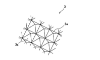
- corrugated pattern 3 is comprised by the some blade part 3a of a quadrangular pyramid shape.
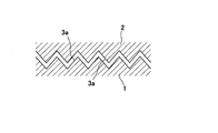
- FIG. 2B is a diagram linearly showing the meshing state of the blade portions 3 a constituting the concavo-convex pattern 3.
- the shape of the blade part 3a is not limited to a quadrangular pyramid shape.
- FIG. 3A is an enlarged schematic view of an A portion in FIG. 3A showing one blade portion 3a on the outer peripheral surface of the embossing rollers 1 and 2 together.
- a hole 6 having an equivalent hole diameter Dmm is formed by embossing at the top 7a (vertex portion) of the convex portion 7 (which is also a concave portion when the vertical view is changed).
- the equivalent hole diameter is a hole diameter when the hole is circular, and the equivalent hole diameter is calculated from the opening area of the hole.
- the thickness t of the metal plate 4 is, for example, about 0.1 to 0.3 mm.
- the plate thickness t of the metal plate 4 may be less than 0.1 mm, but the rigidity becomes low.
- the metal plate 4 having a thickness t exceeding 0.3 mm may be used, but in this case, the pressing force between the embossing rollers 1 and 2, the material of the blade 3 a, and the sharpness of the tip thereof are considered. This is more necessary than when the thickness t is small.
- the material of the metal plate 4 is, for example, aluminum, an aluminum alloy, or stainless steel.
- the porous plate 5 is plastically deformed so that the height H of the unevenness (see FIG. 3A) becomes lower than before pressing by pressing the porous plate 5 in a direction intersecting with the direction D (see FIG. 3A) where the unevenness repeats. By doing so, the hole 6 opened in the top part 7a is made small. Thereby, a fine porous plate is formed.
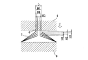
- the porous plate 5 shown in FIG. 3A is set between the molds 8 and 9 having a flat pressing surface, and the upper mold 9 is lowered to form the porous plate 5. Press.
- the porous plate 5 is pressed in a direction orthogonal to the direction D in which the unevenness repeats (in a direction orthogonal to the porous plate 5 when the porous plate 5 is viewed in macro (not considering the unevenness))
- the pressing direction may be an oblique direction instead of the orthogonal direction.
- the height of the convex portion 7 (which is also a concave portion if the vertical direction is changed) becomes low, and the hole 6 becomes small accordingly.
- the larger the amount of reduction by pressing (H1, H2, H3) the smaller the equivalent hole diameter (D1, D2, D3) of the hole 6.
- the sound absorption performance can be controlled by adjusting the perforation pitch and the perforation diameter in the perforated plate forming step and adjusting the reduction amount in the subsequent pore reduction step.
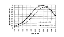
- FIG. 5 shows the sound absorption coefficient of a perforated plate (comparative example) in which many small holes are made by embossing, and the fine perforated plate (example) in which the perforated plate according to the comparative example is pressed to reduce the holes. It is a graph which shows a sound absorption coefficient.
- the hole diameter of the porous plate according to the comparative example is ⁇ 0.1 mm, and the aperture ratio is 1.2%.
- the fine porous plate according to the example has a hole diameter of ⁇ 0.08 mm and an aperture ratio of 0.79%.
- the plate thickness was 0.1 mm, and the thickness of the back air layer was 40 mm.
- the fine perforated plate ( ⁇ 0.08 mm-0.79%) in which the perforated plate ( ⁇ 0.1 mm-1.2%) according to the comparative example is pressed to reduce the pores is 315 Hz. Sound absorption performance is improved in all frequency bands up to 3150 Hz.
- FIG. 6 shows the sound absorption coefficient of a perforated plate (comparative example) in which a large number of small holes are formed by embossing, and a plurality of fine pores that are made smaller by pressing the perforated plate according to the comparative example while changing the amount of reduction. It is a graph which shows the sound absorption rate of a perforated panel (Example).
- the hole diameter of the perforated plate according to the comparative example is ⁇ 0.14 mm, and the aperture ratio is 2.06%.
- the pore diameter of the fine porous plate according to the example and the aperture ratio are ⁇ 0.11 mm, 1.13%, ⁇ 0.09 mm, 0.86%, ⁇ 0.08 mm, 0.55% in order from the smallest reduction amount. It is.
- the plate thickness was 0.1 mm, and the thickness of the back air layer was 40 mm.
- a micro perforated plate ( ⁇ 0.11 mm—1.13%, ⁇ 0.09 mm-0) in which the perforated plate according to the comparative example ( ⁇ 0.14 mm ⁇ 2.06%) was pressed to reduce the pores. .86%, ⁇ 0.08 mm-0.55%) improves the sound absorption performance over the perforated plate according to the comparative example in all frequency bands of 315 Hz to 3150 Hz. Moreover, the sound absorption performance is higher when the amount of reduction is larger and the holes are made finer.
- a perforated plate is formed by forming holes in the top and bottom of the unevenness by forming an unevenness in the plate material by embossing while locally breaking the plate material. Then, by forming a hole in the plate with a needle having a pointed tip (needle-like object), the porous plate may be formed by forming holes in the plate and simultaneously forming holes in the apex portions of the bumps. In this case, unevenness is formed on the plate material by the force of pressing the needle-like object against the plate material. Using a drilling tool such as a sword mountain in which a plurality of needle-like objects are arranged vertically and horizontally at a drilling pitch, the drilling is relatively easy.
- the irregularities formed on the porous plate are staggered irregularities.
- “corrugated” irregularities may be used.
- As a processing method for forming “corrugated” irregularities there is a method called corrugating.
- the holes are formed at the same time as the irregularities are formed in the plate material.
- the holes may be formed in the plate material after the holes are formed in the plate material, or the holes may be formed in the plate material after the irregularities are formed in the plate material. May be.
- a hole 6 may be formed in the oblique portion 7b of the convex portion 7 (which is a concave portion if the vertical view is changed). Even if the hole 6 is made in the oblique portion 7b, the hole 6 becomes smaller when the perforated plate 5 is pressed in the direction intersecting the direction D (see FIG. 3A) where the unevenness repeats and the convex portion 7 is crushed.
- the press surfaces of the molds 8 and 9 partially shown in FIGS. 4A and 4B are assumed to be flat surfaces (the entire perforated plate 5 is pressed with a uniform reduction amount)
- a step is provided on one press surface of the molds 8 and 9, and a portion where the distance between the press surface of the mold 8 and the press surface of the mold 9 facing the mold 8 is different is provided.
- the pressing amount may be varied in the porous plate.
- a plurality of perforated plates 5 may be stacked and pressed together (pressing). By doing so, the productivity of the fine porous plate is improved.
- the perforated plate 5 As a method of pressing the perforated plate 5, the perforated plate 5 is sandwiched between a pair of rollers, in addition to the above-described pressing process in which the perforated plate 5 is sandwiched between the molds 8 and 9 and pressed. There is a method of pressing while feeding.
- a porous plate having a plurality of holes and having unevenness is pressed in a direction intersecting with the direction in which the unevenness is repeated, so that the height of the unevenness is lower than before pressing. In this way, the hole 6 formed in the perforated plate is made small by plastic deformation.
- a plate material having a certain thickness can be easily processed (hole refinement processing). That is, according to the present invention, a finer hole can be easily formed in a plate material having a certain thickness of about 0.1 mm or more.
- the embossing while locally cleaving the plate material or the needle punching process of making a hole in the plate material with a needle-like material forms the irregularities in the plate material and at the same time opens the holes at the apex portions of the irregularities, and the porous A perforated plate forming step for forming a plate, and pressing the perforated plate in a direction intersecting with the direction in which the unevenness repeats and plastically deforming so that the height of the unevenness is lower than before pressing, thereby opening the apex portion. It is preferable to provide a hole reduction step for reducing the formed holes.
- the reduction amount of the hole can be predicted more easily than when the holes made at other parts are made smaller. This makes it easy to control the sound absorption performance.
- the plate material around the hole is partially overlapped in the hole reduction step.
- the rigidity around the hole is increased, the structural damping performance of the porous plate is improved, and the plate is less likely to vibrate.
- the sound absorption efficiency in the porous portion is improved. That is, the sound absorbing performance of the fine porous plate is improved.
- the perforated plate In order to make it easier to overlap the plate material around the holes, it is preferable to press the perforated plate in a direction orthogonal to the direction in which the unevenness is repeated in the hole reduction step.
- the amount of pressing may be varied in the porous plate.
- the equivalent hole diameter of the holes can be easily made different in one porous plate 5, and noise in a wide frequency band can be reduced.
- the sound absorbing characteristics can be enhanced by making the pores of the porous sound absorbing plate smaller, and it can also be applied to a thick plate material having a thickness of 0.1 mm or more.
Landscapes
- Physics & Mathematics (AREA)
- Engineering & Computer Science (AREA)
- Acoustics & Sound (AREA)
- Multimedia (AREA)
- Soundproofing, Sound Blocking, And Sound Damping (AREA)
Abstract
複数の孔があけられているとともに凹凸を有する多孔板を、凹凸が繰り返す方向と交差する方向に押圧して凹凸の高さが押圧前よりも低くなるように塑性変形させることで、多孔板にあけられた孔を小さくする。
Description
本発明は、吸音材として用いられる微細多孔板の製造方法に関する。
吸音材として用いられる多孔板は、その孔径を小さくすることで吸音性能が向上することが知られている。金属材に多数の小さな孔をあける方法として、例えば特許文献1、2に記載された方法がある。
特許文献1に記載の孔あけ方法は、0.1mm程度の厚みの金属箔(例えばアルミ箔)にφ0.1mm程度の微細な孔を好適にあける方法である。金属ロールと受けロールとの間に金属箔を介挿させながら、金属ロールの表面に設けた突起で微細な孔を金属箔にあける。微細な孔をあけるために、突起の高さ、ロール表面からの突起の立ち上がり角度などを規定している。特許文献1に記載の孔あけ方法によると、厚みが0.1mm以下の金属箔にφ0.1mm以下の微細な孔を好適にあけることができる。
特許文献2の段落0017、図2には、0.1mm以上の厚みの金属板に微細な孔をあけるのに好適な方法が記載されている。金属板にエンボス加工を施し、その際、局部的に金属板を裂開させることで微細な孔を形成する。金属板に形成される孔の等価孔径は0.1mm程度となる。この方法で形成される孔は、通常、円形にはならない。等価孔径とは、孔が円形であったとした場合の孔径のことであり、孔の開口面積から等価孔径は算出される。
特許文献1に記載の孔あけ方法によると、φ0.1mm以下の微細な孔を金属材にあけることができる。しかしながら、この方法により好適に孔があけられるのは、厚みが0.1mm以下の金属箔である。多孔板吸音は、孔内を音が伝搬する過程で減衰するという原理で吸音するものであり、金属材の厚みが薄いと剛性が低いので、製造された微細多孔板(微細多孔箔)を吸音材として用いた場合、箔が振動することで吸音性能を効率良く発揮させることができない。また、微細多孔板(微細多孔箔)がそれ自体で自立しないので、吸音構造体を形成し難いという課題もある。
このため、いわゆる箔よりも厚い0.1mm以上の厚みの金属板にエンボス加工を施してなる特許文献2に記載の微細多孔板が吸音材として好適に使用される。この微細多孔板の方が、板の剛性が高いからである。
しかしながら、特許文献2に記載のエンボス加工による孔あけ方法により得られる孔の径は、前記したように0.1mm程度であり、微細な孔であるほど吸音率が高くなる多孔板吸音では吸音性能に限界がある。
本発明は、上記事情に鑑みてなされたものであって、その目的は、0.1mm程度以上のある程度の厚みを有する板材に、従来よりも微細な孔を形成することができる微細多孔板の製造方法を提供することである。
本発明に係る微細多孔板の製造方法は、複数の孔があけられているとともに凹凸を有する多孔板を、凹凸が繰り返す方向と交差する方向に押圧して凹凸の高さが押圧前よりも低くなるように塑性変形させることで、多孔板にあけられた孔を小さくすることを特徴とする。
本発明によると、0.1mm程度以上のある程度の厚みを有する板材に、従来よりも微細な孔を形成することができる。
以下、本発明を実施するための形態について図面を参照しつつ説明する。
(エンボス加工による穿孔)
まず、板材を局部的に裂開させながらのエンボス加工により、板材に凹凸を形成すると同時に凹凸の頂点部分に孔をあけて多孔板を形成する(多孔板形成工程)。この穿孔加工を行う装置の例について図1~図2Bを参照しつつ説明する。図1に示すエンボスローラ1,2は、例えば、一方のエンボスローラ1は軸心回りに回転自在な状態で固定され、他方のエンボスローラ2は軸心回りに回転自在な状態で対向するエンボスローラ1に対して押し付けられる。エンボスローラ1,2の外周面には、それぞれ、凹凸模様3が形成されている。図2Aに示すように、凹凸模様3は四角錐状の複数の刃部3aで構成されている。図2Bは、凹凸模様3を構成する刃部3aの噛合状態を直線的に示す図である。なお、刃部3aの形状は、四角錐状に限られることはない。
まず、板材を局部的に裂開させながらのエンボス加工により、板材に凹凸を形成すると同時に凹凸の頂点部分に孔をあけて多孔板を形成する(多孔板形成工程)。この穿孔加工を行う装置の例について図1~図2Bを参照しつつ説明する。図1に示すエンボスローラ1,2は、例えば、一方のエンボスローラ1は軸心回りに回転自在な状態で固定され、他方のエンボスローラ2は軸心回りに回転自在な状態で対向するエンボスローラ1に対して押し付けられる。エンボスローラ1,2の外周面には、それぞれ、凹凸模様3が形成されている。図2Aに示すように、凹凸模様3は四角錐状の複数の刃部3aで構成されている。図2Bは、凹凸模様3を構成する刃部3aの噛合状態を直線的に示す図である。なお、刃部3aの形状は、四角錐状に限られることはない。
エンボスローラ1,2間に金属板4を挟み込み、エンボスローラ1を回転させることで金属板4を送っていく。その際に、金属板4に押し付けられるエンボスローラの刃部3aが、当該金属板4に凹凸を付けるとともに金属板4を局部的に裂開して孔6をあける。これにより、凹凸を有するとともに当該凹凸の頂点部分に孔6があいた多孔板5が形成される(図3A)。図3Bは、エンボスローラ1,2の外周面の1つの刃部3aを合わせて示す図3AのA部の拡大模式図である。凸部7(上下見方を変えれば凹部でもある)の頂部7a(頂点部分)にエンボス加工によって等価孔径Dmmの孔6があくとしている。前記したように、等価孔径とは、孔が円形であったとした場合の孔径のことであり、孔の開口面積から等価孔径は算出される。
金属板4の板厚tは、例えば、0.1~0.3mm程度である。金属板4の板厚tは0.1mm未満であってもよいが、剛性が低くなってしまう。逆に、0.3mmを超える板厚tの金属板4であってもよいが、この場合は、エンボスローラ1,2間の押し付け力、刃部3aの材質、その先端の鋭さの考慮が板厚tが薄い場合よりも必要になってくる。金属板4の材質は、例えば、アルミニウム、アルミニウム合金、ステンレスである。
(孔縮小工程)
次に、凹凸が繰り返す方向D(図3A参照)と交差する方向に多孔板5を押圧して凹凸の高さH(図3A参照)が押圧前よりも低くなるように多孔板5を塑性変形させることで、頂部7aにあけられた孔6を小さくする。これにより、微細多孔板が形成される。
次に、凹凸が繰り返す方向D(図3A参照)と交差する方向に多孔板5を押圧して凹凸の高さH(図3A参照)が押圧前よりも低くなるように多孔板5を塑性変形させることで、頂部7aにあけられた孔6を小さくする。これにより、微細多孔板が形成される。
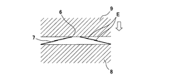
図4A,Bにプレス加工の一部を示すように、プレス面が平坦な金型8,9の間に図3Aに示す多孔板5をセットし、上金型9を下げて多孔板5をプレスする。本実施形態の場合、凹凸が繰り返す方向Dに対して直交する方向に(多孔板5をマクロで見たときの(凹凸を考慮しない)多孔板5に対する直交方向に)多孔板5をプレスしているが、プレス方向は、上記直交方向ではなく、斜め方向であってもよい。
多孔板5をプレスすると、その凸部7(上下見方を変えれば凹部でもある)の高さが低くなり、これに従って孔6は小さくなる。図4Aに示したように、プレスによる圧下量(H1、H2、H3)が大きくなればなるほど、孔6の等価孔径(D1、D2、D3)は小さくなる。
また、凸部7(上下見方を変えれば凹部でもある)の頂部7aにあいた孔6を有する多孔板5をプレスする際、図4Bに示したように、孔6周りの板材が部分的に重畳するように凸部7を潰すことが好ましい。なお、重畳した部分に符号Eを付した。「重畳する」とは、折り重なったような形態になることである。
(吸音性能の調整)
前記した多孔板形成工程において穿孔ピッチおよび穿孔径の調整を行い、前記したその後の孔縮小工程において圧下量の調整を行うことで、吸音性能をコントロールすることができる。
前記した多孔板形成工程において穿孔ピッチおよび穿孔径の調整を行い、前記したその後の孔縮小工程において圧下量の調整を行うことで、吸音性能をコントロールすることができる。
(吸音率の比較)
図5は、エンボス加工により多数の小さな孔があけられた多孔板(比較例)の吸音率と、当該比較例に係る多孔板をプレス加工して孔を小さくした微細多孔板(実施例)の吸音率とを示すグラフである。比較例に係る多孔板の孔径はφ0.1mmであり、その開口率は1.2%である。実施例に係る微細多孔板の孔径はφ0.08mmであり、その開口率は0.79%である。なお、板厚は0.1mm、背後空気層の層厚は40mmとした。
図5は、エンボス加工により多数の小さな孔があけられた多孔板(比較例)の吸音率と、当該比較例に係る多孔板をプレス加工して孔を小さくした微細多孔板(実施例)の吸音率とを示すグラフである。比較例に係る多孔板の孔径はφ0.1mmであり、その開口率は1.2%である。実施例に係る微細多孔板の孔径はφ0.08mmであり、その開口率は0.79%である。なお、板厚は0.1mm、背後空気層の層厚は40mmとした。
図5からわかるように、比較例に係る多孔板(φ0.1mm-1.2%)をプレス加工して孔を小さくした微細多孔板(φ0.08mm-0.79%)の方が、315Hz~3150Hzの全ての周波数帯域で吸音性能が向上する。
図6は、エンボス加工により多数の小さな孔があけられた多孔板(比較例)の吸音率と、当該比較例に係る多孔板を圧下量を変えてプレス加工して孔を小さくした複数の微細多孔板(実施例)の吸音率とを示すグラフである。
比較例に係る多孔板の孔径はφ0.14mmであり、その開口率は2.06%である。実施例に係る微細多孔板の孔径、およびその開口率は、圧下量の小さいものから順に、φ0.11mm,1.13%、φ0.09mm,0.86%、φ0.08mm,0.55%である。なお、板厚は0.1mm、背後空気層の層厚は40mmとした。
図6からわかるように、比較例に係る多孔板(φ0.14mm-2.06%)をプレス加工して孔を小さくした微細多孔板(φ0.11mm-1.13%、φ0.09mm-0.86%、φ0.08mm-0.55%)の方が、315Hz~3150Hzの全ての周波数帯域で、比較例に係る多孔板よりも吸音性能が向上する。また、圧下量が大きく孔をより微細化した方が、吸音性能が高い。
(その他の実施形態)
前記した実施形態では、板材を局部的に裂開させながらのエンボス加工により、板材に凹凸を形成すると同時に凹凸の頂点部分に孔をあけて多孔板を形成する例を示したが、これに代えて、先端の尖った針(針状物)で板材に孔をあける針穿孔加工により、板材に凹凸を形成すると同時に凹凸の頂点部分に孔をあけて多孔板を形成してもよい。なお、この場合、針状物を板材に押し付ける力で、板材に凹凸を形成する。複数の針状物を穿孔ピッチで縦横に並べて固定した剣山のような穿孔具を用いると孔あけが比較的容易となる。
前記した実施形態では、板材を局部的に裂開させながらのエンボス加工により、板材に凹凸を形成すると同時に凹凸の頂点部分に孔をあけて多孔板を形成する例を示したが、これに代えて、先端の尖った針(針状物)で板材に孔をあける針穿孔加工により、板材に凹凸を形成すると同時に凹凸の頂点部分に孔をあけて多孔板を形成してもよい。なお、この場合、針状物を板材に押し付ける力で、板材に凹凸を形成する。複数の針状物を穿孔ピッチで縦横に並べて固定した剣山のような穿孔具を用いると孔あけが比較的容易となる。
多孔板に形成される凹凸は、前記した実施形態によると千鳥状の凹凸となる。千鳥状の凹凸ではなく「波形」の凹凸であってもよい。「波形」の凹凸を形成する加工方法としては、コルゲート加工という方法がある。
前記した実施形態では、板材に凹凸を形成すると同時に孔をあけているが、板材に孔をあけた後に板材に凹凸を形成してもよいし、板材に凹凸を形成した後に板材に孔をあけてもよい。この場合、図3Bに符号7bを記しているように、多孔板の凸部7(上下見方を変えれば凹部でもある)の斜部7bに孔6をあけてもよい。斜部7bに孔6をあけたとしても、凹凸が繰り返す方向D(図3A参照)と交差する方向に多孔板5を押圧して凸部7を潰すように圧下させると孔6は小さくなる。
また、図4A,Bに一部を示す金型8,9のプレス面は全面が平坦な面を想定しているが(多孔板5はその全体が一様な圧下量でプレスされる)、例えば図7に示したように、金型8,9の一方のプレス面に段差を設けて、金型8のプレス面と、これに対向する金型9のプレス面との間隔が異なる部位を設けて、1枚の多孔板5の中で圧下量(押圧量)を異ならせてもよい。すなわち、凹凸が繰り返す方向と交差する方向に多孔板を押圧して凹凸の高さが押圧前よりも低くなるように塑性変形させる際、多孔板の中で押圧量を異ならせてもよい。こうすることで、1枚の多孔板5の中で孔の等価孔径を容易に異ならせることができ、広い周波数帯域の騒音を低減できるようになる。
また、孔縮小工程において、多孔板5を1枚ごとプレス加工(押圧加工)するのではなく、複数枚の多孔板5を重ね合わせてまとめてプレス加工(押圧加工)してもよい。こうすることで、微細多孔板の生産性が向上する。
多孔板5を押圧する方法としては、金型8,9間に多孔板5を挟み込んで押圧する前記したプレス加工の他に、1対のローラ間に多孔板5を挟み込んで、多孔板5を送りながら押圧する方法がある。
その他に、当業者が想定できる範囲で種々の変更を行えることは勿論である。
(作用・効果)
本発明の微細多孔板の製造方法は、複数の孔があけられているとともに凹凸を有する多孔板を、凹凸が繰り返す方向と交差する方向に押圧して凹凸の高さが押圧前よりも低くなるように塑性変形させることで、多孔板にあけられた孔6を小さくすることを特徴とする。
本発明の微細多孔板の製造方法は、複数の孔があけられているとともに凹凸を有する多孔板を、凹凸が繰り返す方向と交差する方向に押圧して凹凸の高さが押圧前よりも低くなるように塑性変形させることで、多孔板にあけられた孔6を小さくすることを特徴とする。
多孔板を押圧することで孔を小さくするので、ある程度の厚みを有する板材でも容易に加工(孔微細化加工)することができる。すなわち、本発明によると、0.1mm程度以上のある程度の厚みを有する板材に、従来よりも微細な孔を容易に形成することができる。
本発明において、板材を局部的に裂開させながらのエンボス加工、または針状物で板材に孔をあける針穿孔加工により、板材に凹凸を形成すると同時に凹凸の頂点部分に孔をあけて前記多孔板を形成する多孔板形成工程と、凹凸が繰り返す方向と交差する方向に前記多孔板を押圧して凹凸の高さが押圧前よりも低くなるように塑性変形させることで、前記頂点部分にあけられた孔を小さくする孔縮小工程と、を備えることが好ましい。
凹凸の頂点部分にあけた孔を小さくすると、その他の部位にあけた孔を小さくする場合に比べて、孔の縮小量を予想し易い。これにより、吸音性能がコントロールし易くなる。
また本発明において、前記孔縮小工程において孔の周りの板材を部分的に重畳させることが好ましい。孔周りの板材が重畳した形状となると、孔周りの剛性が高まり、多孔板の構造減衰性能が向上して板が振動しにくくなる。板振動が低減することで、多孔部での吸音効率が向上する。すなわち、微細多孔板の吸音性能が向上する。
孔周りの板材をより重畳し易くするためには、前記孔縮小工程において、凹凸が繰り返す方向と直交する方向に多孔板を押圧することが好ましい。
さらに本発明において、凹凸が繰り返す方向と交差する方向に多孔板を押圧して凹凸の高さが押圧前よりも低くなるように塑性変形させる際、多孔板の中で押圧量を異ならせることが好ましい。こうすることで、1枚の多孔板5の中で孔の等価孔径を容易に異ならせることができ、広い周波数帯域の騒音を低減できるようになる。
本発明を詳細にまた特定の実施態様を参照して説明したが、本発明の精神と範囲を逸脱することなく様々な変更や修正を加えることができることは当業者にとって明らかである。
本出願は、2015年11月5日出願の日本特許出願(特願2015-217280)に基づくものであり、その内容はここに参照として取り込まれる。
本出願は、2015年11月5日出願の日本特許出願(特願2015-217280)に基づくものであり、その内容はここに参照として取り込まれる。
本発明によれば、多孔吸音板の孔をより小さくして吸音特性を高めることができ、しかも、板厚が0.1mm以上と厚い板材にも適用できる。
1、2:エンボスローラ
3:凹凸模様
3a:刃部
4:金属板
5:多孔板
6:孔
7:凸部
7a:頂部(頂点部分)
7b:斜部
3:凹凸模様
3a:刃部
4:金属板
5:多孔板
6:孔
7:凸部
7a:頂部(頂点部分)
7b:斜部
Claims (5)
- 複数の孔があけられているとともに凹凸を有する多孔板を、凹凸が繰り返す方向と交差する方向に押圧して凹凸の高さが押圧前よりも低くなるように塑性変形させることで、前記孔を小さくすることを特徴とする、微細多孔板の製造方法。
- 請求項1に記載の微細多孔板の製造方法において、
板材を局部的に裂開させながらのエンボス加工、または針状物で板材に孔をあける針穿孔加工により、板材に凹凸を形成すると同時に凹凸の頂点部分に孔をあけて前記多孔板を形成する多孔板形成工程と、
凹凸が繰り返す方向と交差する方向に前記多孔板を押圧して凹凸の高さが押圧前よりも低くなるように塑性変形させることで、前記頂点部分にあけられた孔を小さくする孔縮小工程と、
を備えることを特徴とする、微細多孔板の製造方法。 - 請求項2に記載の微細多孔板の製造方法において、
前記孔縮小工程において、前記孔の周りの板材を部分的に重畳させることを特徴とする、微細多孔板の製造方法。 - 請求項2または3に記載の微細多孔板の製造方法において、
前記孔縮小工程において、凹凸が繰り返す方向と直交する方向に前記多孔板を押圧することを特徴とする、微細多孔板の製造方法。 - 請求項1に記載の微細多孔板の製造方法において、
凹凸が繰り返す方向と交差する方向に前記多孔板を押圧して凹凸の高さが押圧前よりも低くなるように塑性変形させる際、前記多孔板の中で押圧量を異ならせることを特徴とする、微細多孔板の製造方法。
Priority Applications (1)
| Application Number | Priority Date | Filing Date | Title |
|---|---|---|---|
| CN201680059543.8A CN108352154B (zh) | 2015-11-05 | 2016-10-31 | 微细多孔板的制造方法 |
Applications Claiming Priority (2)
| Application Number | Priority Date | Filing Date | Title |
|---|---|---|---|
| JP2015217280A JP6560593B2 (ja) | 2015-11-05 | 2015-11-05 | 微細多孔板の製造方法 |
| JP2015-217280 | 2015-11-05 |
Publications (1)
| Publication Number | Publication Date |
|---|---|
| WO2017077966A1 true WO2017077966A1 (ja) | 2017-05-11 |
Family
ID=58662941
Family Applications (1)
| Application Number | Title | Priority Date | Filing Date |
|---|---|---|---|
| PCT/JP2016/082212 Ceased WO2017077966A1 (ja) | 2015-11-05 | 2016-10-31 | 微細多孔板の製造方法 |
Country Status (3)
| Country | Link |
|---|---|
| JP (1) | JP6560593B2 (ja) |
| CN (1) | CN108352154B (ja) |
| WO (1) | WO2017077966A1 (ja) |
Families Citing this family (2)
| Publication number | Priority date | Publication date | Assignee | Title |
|---|---|---|---|---|
| KR102843352B1 (ko) * | 2019-12-10 | 2025-08-06 | 현대자동차주식회사 | 타공판재 및 이를 이용한 흡차음 복합판재 |
| JP7504645B2 (ja) * | 2020-04-06 | 2024-06-24 | 株式会社ヒロタニ | 車両用遮熱防音材 |
Citations (3)
| Publication number | Priority date | Publication date | Assignee | Title |
|---|---|---|---|---|
| JPH10303355A (ja) * | 1997-04-28 | 1998-11-13 | Mitsui High Tec Inc | 半導体装置 |
| JP2002332073A (ja) * | 2001-05-08 | 2002-11-22 | Rootarii Kk | 微小穿孔シート |
| JP2008138505A (ja) * | 2006-11-02 | 2008-06-19 | Kobe Steel Ltd | 吸音構造体 |
Family Cites Families (7)
| Publication number | Priority date | Publication date | Assignee | Title |
|---|---|---|---|---|
| TW589504B (en) * | 1997-06-12 | 2004-06-01 | Sharp Kk | Liquid crystal display device |
| JP2001009883A (ja) * | 1999-06-29 | 2001-01-16 | Kuraray Co Ltd | 射出成形法 |
| JP4117740B2 (ja) * | 2002-12-17 | 2008-07-16 | 日立マクセル株式会社 | 金属多孔体とその製造方法 |
| JP4291760B2 (ja) * | 2003-09-05 | 2009-07-08 | 株式会社神戸製鋼所 | 吸音構造体およびその製造方法 |
| WO2006035901A1 (ja) * | 2004-09-29 | 2006-04-06 | Dai Nippon Printing Co., Ltd. | 低艶金属光沢化粧シート、及びそれを積層した積層物 |
| JP5498474B2 (ja) * | 2011-12-14 | 2014-05-21 | 花王株式会社 | 積層不織布の製造方法 |
| KR101716588B1 (ko) * | 2012-06-20 | 2017-03-14 | 미쯔비시 레이온 가부시끼가이샤 | 적층체의 제조 방법, 적층체 및 물품 |
-
2015
- 2015-11-05 JP JP2015217280A patent/JP6560593B2/ja active Active
-
2016
- 2016-10-31 CN CN201680059543.8A patent/CN108352154B/zh active Active
- 2016-10-31 WO PCT/JP2016/082212 patent/WO2017077966A1/ja not_active Ceased
Patent Citations (3)
| Publication number | Priority date | Publication date | Assignee | Title |
|---|---|---|---|---|
| JPH10303355A (ja) * | 1997-04-28 | 1998-11-13 | Mitsui High Tec Inc | 半導体装置 |
| JP2002332073A (ja) * | 2001-05-08 | 2002-11-22 | Rootarii Kk | 微小穿孔シート |
| JP2008138505A (ja) * | 2006-11-02 | 2008-06-19 | Kobe Steel Ltd | 吸音構造体 |
Also Published As
| Publication number | Publication date |
|---|---|
| CN108352154B (zh) | 2022-04-08 |
| JP2017090556A (ja) | 2017-05-25 |
| CN108352154A (zh) | 2018-07-31 |
| JP6560593B2 (ja) | 2019-08-14 |
Similar Documents
| Publication | Publication Date | Title |
|---|---|---|
| TWI647363B (zh) | Misaligned conduction multi-perforated sound absorbing panel | |
| US6555246B1 (en) | Method of producing a sound-absorbent insulating element and insulating element produced according to this method | |
| JP6560593B2 (ja) | 微細多孔板の製造方法 | |
| JP6844255B2 (ja) | キャラクターラインを有するパネルの製造装置および製造方法 | |
| KR101795295B1 (ko) | 흡차음 타공판재 | |
| KR101205165B1 (ko) | 금속판재에 미세구멍을 제작하는 방법 | |
| JP5540228B2 (ja) | 金属箔の加工歪矯正装置及び加工歪矯正方法 | |
| JP2011156581A (ja) | 凹凸金属板 | |
| JPH1058056A (ja) | パンチプレス装置における多数穿孔金属板の製造方法 | |
| JP2009241125A (ja) | プレス金型 | |
| JP5707555B2 (ja) | 金属箔の穿孔装置及び金属箔の穿孔方法 | |
| JP6560804B1 (ja) | 波板形成方法及びその方法による製造品 | |
| KR20080039518A (ko) | 링형상부재의 제조방법 | |
| KR102843352B1 (ko) | 타공판재 및 이를 이용한 흡차음 복합판재 | |
| CN108730033B (zh) | 透声金属板和使用该透声金属板的吸音复合板 | |
| JP5557374B2 (ja) | プレス成形金型 | |
| JP6170413B2 (ja) | 板状ワークの打抜き加工方法及びパンチ金型 | |
| JP5323465B2 (ja) | 吸音板および該吸音板の製造方法 | |
| KR20190121041A (ko) | 열차단 판재 제작 방법 및 그 방법에 의해 제작된 열차단 판재 | |
| KR101521133B1 (ko) | 홀의 라운드 형성 제조방법 | |
| JP4168930B2 (ja) | ロール成形装置及びロール成形方法 | |
| JP3202526B2 (ja) | 金属板のプレス加工装置 | |
| JP2010115705A (ja) | 多孔板の製造方法及び多孔板 | |
| JP5872506B2 (ja) | プリント配線板の製造方法 | |
| JP2000296569A (ja) | 部分潰し片段の製造方法 |
Legal Events
| Date | Code | Title | Description |
|---|---|---|---|
| 121 | Ep: the epo has been informed by wipo that ep was designated in this application |
Ref document number: 16862026 Country of ref document: EP Kind code of ref document: A1 |
|
| NENP | Non-entry into the national phase |
Ref country code: DE |
|
| 122 | Ep: pct application non-entry in european phase |
Ref document number: 16862026 Country of ref document: EP Kind code of ref document: A1 |