WO2017073441A1 - 鉄道車両用操舵台車 - Google Patents
鉄道車両用操舵台車 Download PDFInfo
- Publication number
- WO2017073441A1 WO2017073441A1 PCT/JP2016/081045 JP2016081045W WO2017073441A1 WO 2017073441 A1 WO2017073441 A1 WO 2017073441A1 JP 2016081045 W JP2016081045 W JP 2016081045W WO 2017073441 A1 WO2017073441 A1 WO 2017073441A1
- Authority
- WO
- WIPO (PCT)
- Prior art keywords
- steering
- link
- vehicle
- lever
- axle
- Prior art date
- Legal status (The legal status is an assumption and is not a legal conclusion. Google has not performed a legal analysis and makes no representation as to the accuracy of the status listed.)
- Ceased
Links
Images





Classifications
-
- B—PERFORMING OPERATIONS; TRANSPORTING
- B61—RAILWAYS
- B61F—RAIL VEHICLE SUSPENSIONS, e.g. UNDERFRAMES, BOGIES OR ARRANGEMENTS OF WHEEL AXLES; RAIL VEHICLES FOR USE ON TRACKS OF DIFFERENT WIDTH; PREVENTING DERAILING OF RAIL VEHICLES; WHEEL GUARDS, OBSTRUCTION REMOVERS OR THE LIKE FOR RAIL VEHICLES
- B61F5/00—Constructional details of bogies; Connections between bogies and vehicle underframes; Arrangements or devices for adjusting or allowing self-adjustment of wheel axles or bogies when rounding curves
- B61F5/38—Arrangements or devices for adjusting or allowing self- adjustment of wheel axles or bogies when rounding curves, e.g. sliding axles, swinging axles
- B61F5/44—Adjustment controlled by movements of vehicle body
-
- B—PERFORMING OPERATIONS; TRANSPORTING
- B61—RAILWAYS
- B61F—RAIL VEHICLE SUSPENSIONS, e.g. UNDERFRAMES, BOGIES OR ARRANGEMENTS OF WHEEL AXLES; RAIL VEHICLES FOR USE ON TRACKS OF DIFFERENT WIDTH; PREVENTING DERAILING OF RAIL VEHICLES; WHEEL GUARDS, OBSTRUCTION REMOVERS OR THE LIKE FOR RAIL VEHICLES
- B61F5/00—Constructional details of bogies; Connections between bogies and vehicle underframes; Arrangements or devices for adjusting or allowing self-adjustment of wheel axles or bogies when rounding curves
- B61F5/26—Mounting or securing axle-boxes in vehicle or bogie underframes
- B61F5/30—Axle-boxes mounted for movement under spring control in vehicle or bogie underframes
- B61F5/301—Axle-boxes mounted for movement under spring control in vehicle or bogie underframes incorporating metal springs
- B61F5/302—Leaf springs
-
- B—PERFORMING OPERATIONS; TRANSPORTING
- B61—RAILWAYS
- B61F—RAIL VEHICLE SUSPENSIONS, e.g. UNDERFRAMES, BOGIES OR ARRANGEMENTS OF WHEEL AXLES; RAIL VEHICLES FOR USE ON TRACKS OF DIFFERENT WIDTH; PREVENTING DERAILING OF RAIL VEHICLES; WHEEL GUARDS, OBSTRUCTION REMOVERS OR THE LIKE FOR RAIL VEHICLES
- B61F5/00—Constructional details of bogies; Connections between bogies and vehicle underframes; Arrangements or devices for adjusting or allowing self-adjustment of wheel axles or bogies when rounding curves
- B61F5/26—Mounting or securing axle-boxes in vehicle or bogie underframes
- B61F5/30—Axle-boxes mounted for movement under spring control in vehicle or bogie underframes
- B61F5/32—Guides, e.g. plates, for axle-boxes
- B61F5/325—The guiding device including swinging arms or the like to ensure the parallelism of the axles
Definitions
- the present invention relates to a railway vehicle steering carriage using a link mechanism.
- the steering cart of Patent Document 1 has a link mechanism (Z link), and the Z link has a vertical link and two horizontal links.
- the vertical link is rotatably attached to the bogie frame and is connected to the vehicle body via a parallel link.
- two horizontal links are attached to the vertical link.
- the two horizontal links extend from the vertical link to one side and the other in the front-rear direction, and each horizontal link is also attached to a shaft box provided on each wheel shaft.
- the vehicle body and the cart turn relative to each other when traveling along a curve, and the vertical link rotates.
- the two horizontal links move the axle box in the direction of approaching or separating from each other to lengthen the axial distance on the curved outer rail side and shorten the axial distance on the curved inner rail side to steer the wheel shaft.
- the direction of the yawing direction can be changed.
- the lever ratio is the ratio of the distance between the connection point of each link and the rotation center, and in order to increase the lever ratio, the distance between the connection point of the parallel link and the rotation center is increased. Alternatively, it is necessary to shorten the distance between the connecting point of the horizontal link and the rotation center. In order to increase the distance between the connecting point of the parallel link and the rotation center, it is necessary to increase the length of the vertical link.
- an object of the present invention is to provide a steering carriage that can increase the degree of freedom in designing a steering mechanism.
- the railroad steering bogie of the present invention includes a bogie frame that supports a vehicle body or a bolster so as to be capable of relative rotation about a vertical axis, two wheel shafts having an axle and a pair of wheels, and a shaft that houses a bearing that supports the axle.
- An axle box support device having a shaft beam for connecting the box to the carriage frame; and a steering mechanism for steering at least one of the two wheel shafts in response to relative turning of the vehicle body or the bolster.
- a steering lever that rotates about a fulcrum axis with respect to the bogie frame; a link that connects the vehicle body or the bolster and the steering lever; and that is linked to relative turning of the bogie frame and the vehicle body or the bolster; And connecting at least one steering link for connecting the steering lever and the shaft beam and steering the wheel shaft by displacing the axle box via the shaft beam in conjunction with the pivoting operation of the steering lever.
- the steering lever has a rotation center member that is a shaft portion or a groove portion that rotates around a fulcrum axis, and the rotation center member is disposed at a position offset in the axial direction with respect to the steering link. Is.
- the rotation center member is disposed at a position offset in the axial direction with respect to the steering link. Therefore, even if the steering link is designed to be closer to the fulcrum axis, the steering link rotates. There is no contact with the moving center member. Therefore, regarding the arrangement position of the steering link, restrictions on the direction perpendicular to the axial direction can be reduced, and the degree of design freedom can be increased with respect to the arrangement position of the rotation center member and the arrangement position of the steering link.
- the degree of freedom in designing the steering mechanism can be increased.
- FIG. 5 is a side sectional view of a part of the steering mechanism of FIG. 4 as viewed from the side.
- FIG. 5 is a rear sectional view of the steering mechanism of FIG. 4 as viewed from the rear.
- FIG. 5 is an exploded view showing a steering lever and a steering link of the steering mechanism of FIG. 4 in an exploded manner.
- FIG. 1 It is a side view which shows the steering operation of the steering trolley
- a railway vehicle steering carriage (hereinafter simply referred to as a “steering carriage”) 1 and 1A according to the first and second embodiments of the present invention will be described with reference to the drawings.
- the concept of the direction used in the following description is used for convenience in description, and does not limit the direction of the configuration of the invention in that direction.
- the steering carts 1, 1A, 1B of the respective embodiments described below are only one embodiment of the present invention. Therefore, the present invention is not limited to the embodiments, and additions, deletions, and changes can be made without departing from the spirit of the invention.
- a railway vehicle 2 shown in FIG. 1 travels on a rail 3 laid on the ground or the like, and includes a vehicle body 4 and a steering carriage 1.
- the vehicle body 4 is formed in a generally box shape that is long in the rail direction, and accommodates passengers or cargo handling.
- a steering carriage 1 is disposed below the vehicle body 4, and the steering carriage 1 supports the vehicle body 4 from below via an air spring 5. Below, the structure of the steering cart 1 is demonstrated in detail.
- the steering carriage 1 includes a carriage frame 11 and a pair of front and rear wheel shafts 12.
- the carriage frame 11 has a pair of side beams 21 and 21 and a horizontal beam 22.
- the pair of side beams 21 and 21 are members extending in the longitudinal direction of the vehicle body 4 (that is, the longitudinal direction of the vehicle, hereinafter referred to as “longitudinal direction”). (Also referred to as “vehicle width direction”).
- the horizontal beam 22 is integrally provided so as to be bridged over the central portion of the pair of side beams 21 and 21, and the carriage frame 11 is formed in an H shape in plan view (see FIG. 2).
- a pair of wheel shafts 12, 12 are arranged in parallel with each other in the longitudinal direction in the carriage frame 11 configured as described above.
- Each wheel axle 12 has an axle 16 and a pair of wheels 17 and 17 as shown in FIG.
- the axle 16 is a rod-shaped member extending in the vehicle width direction.
- a pair of wheels 17 and 17 are integrally provided on the axle 16 in a state of being separated from each other in the axial direction.
- the steering carriage 1 includes a pair of axle boxes 13 and 13 and a pair of axle box support devices 14 and 14 for each axle 12.
- Each of the pair of axle boxes 13 and 13 is provided on both sides in the axial direction of the axle 16 of the wheel shaft 12.
- Each axle box 13 accommodates a bearing 18, for example, a journal bearing, and the bearings 18 rotatably support portions on both sides in the axial direction of the axle 16.
- the pair of axle boxes 13 and 13 are provided with a pair of axle box support devices 14 and 14, respectively.
- Each axle box 13 is connected to the carriage frame 11 by the axle box support device 14 (see FIG. 1).
- the shaft box support device 14 is, for example, a shaft beam type shaft box support device, and includes a shaft beam 23 and a shaft spring 24 (see also FIG. 1).
- the shaft beam 23 has a shaft beam main body portion 23 a extending in the longitudinal direction, and a base end portion 23 b of the shaft beam main body portion 23 a is connected to the shaft box 13.
- a shaft spring 24 is provided at the upper end portion of the axle box 13, and the axle spring 24 is interposed between the portion directly above the axle box 13 in the side beam 21 of the carriage frame 11 and the axle box 13. .
- a shaft beam tip 23c is provided at the tip of the shaft beam main body 23a.
- the shaft beam tip 23c extends in the longitudinal direction from the shaft beam main body 23a and extends in the vehicle vertical direction and the vehicle to the carriage frame 11. It is connected so as to be swingable in the width direction.
- the steering cart 1 configured as described above is a cart with a bolster and has a pillow beam 25.
- the pillow beam 25 is provided on the horizontal beam 22 via a support shaft (not shown), and rotates relative to the horizontal beam 22 around the vertical axis. Further, the pillow beam 25 supports the vehicle body 4 via the air spring 5 and is connected to the vehicle body 4 by a bolster anchor 26. Therefore, the pillow beam 25 is designed to turn integrally with the vehicle body 4.
- the steering cart 1 includes a pair of steering mechanisms 15 for steering the pair of wheel shafts 12 according to the turning motion of the pillow beam 25 (that is, turning the pair of wheel shafts 12 in the yawing direction).
- one pair of steering mechanisms 15 is provided for each of the pair of side beams 21 and 21 of the carriage frame 11, and each is disposed mirror-symmetrically with respect to the vehicle body center line. Yes.
- the steering cart 1 is shown by cutting both longitudinal ends of the pair of side beams 21 and 21.
- Each of the pair of steering mechanisms 15 has the same configuration.
- the connection link 31, the steering lever 32, the first steering link 33, and the second steering link 34 are connected.
- the connection link 31 is a member that extends substantially in the longitudinal direction. As shown in FIG. 1, one end in the longitudinal direction of the connecting link 31 is connected to the pillow beam 25 via a pillow beam side link receiving member 35.
- one end in the longitudinal direction of the connecting link 31 is attached to the pillow beam side link receiving member 35 so as to be capable of relative rotation with respect to the vehicle vertical direction, and relative rotation between the pillow beam 25 and the horizontal beam 22 of the carriage frame 11 is performed. It moves in the longitudinal direction in conjunction with the movement. Further, the other end portion in the longitudinal direction of the connection link 31 is connected to the steering lever 32.
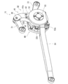
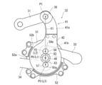
- the steering lever 32 is a plate-like member having a slanted ball shape (that is, an inverted comma shape) in side view as shown in FIG. 5, and rotates around the fulcrum axis L1.
- FIG. 5 shows a housing 49 (described later) cut so that the steering lever 32 can be seen.
- the steering lever 32 has a lever main body 41 and a lid body 42, and the lever main body 41 is formed in a slanting ball shape in a side view.
- the curved portion 41a constituting the upper portion of the lever body 41 is curved so as to extend in the vehicle vertical direction and to be recessed in one longitudinal direction, and the upper portion of the curved portion 41a is as shown in FIG. Divided into two branches.
- the shaft member 36 is bridged between the parts 41c and 41d which are divided into the forked part of the curved part 41a.
- the shaft member 36 has a spherical bush 36 a at an intermediate portion, and the spherical bush 36 a is inserted through the connecting link 31.
- the accommodating portion 41b constituting the lower portion of the lever body 41 is circular in a side view as shown in FIG. 5, and around its central axis (fulcrum axis L1) as shown in FIG. A recess 41e that is open on both sides in the longitudinal direction is formed.
- a lid 42 is provided in the accommodating portion 41 b so as to cover the recess 41 e, and an accommodating space 43 is formed in the steering lever 32 by covering the lid 42.
- Each of a pair of shaft portions 45 and 46 serving as a rotation shaft of the steering lever 32 is formed on the back surface of the housing portion 41 b and the surface of the lid body 42.
- the pair of shaft portions 45 and 46 is formed in a substantially columnar shape, and extends along the central axis of the accommodating portion 41b, that is, along the fulcrum axis L1.
- the pair of shaft portions 45 and 46 formed in this manner are arranged so as to be separated from each other in the axial direction in which the fulcrum axis L1 extends.
- cylindrical thrust bushes 47 and 48 are externally mounted on the shaft portions 45 and 46, and the shaft portions 45 and 46 are attached to the housing 49 via the thrust bushes 47 and 48.
- the housing 49 accommodates at least a part of the steering lever 32, specifically, the accommodating portion 41b and the lid 42.
- the housing 49 includes a housing seat 50, a rear box 51, a front box 52, and a box lid 53.
- the housing seat 50 is a substantially rounded circular plate-like member extending in the longitudinal direction in a side view, and the back surface thereof is fixed to the outer surface of the side beam 21 of the carriage frame 11.
- a rear box 51 is fixed to the surface of the housing seat 50 by a fastening member such as a bolt.
- the rear box 51 is formed in a substantially circular shape in a side view, and a bearing hole 51a is formed around the center thereof.
- the shaft portion 45 of the housing portion 41 b is fitted into the bearing hole 51 a via the thrust bush 47, and the shaft portion 45 rotates relative to the rear box 51.
- the rear box 51 is provided with a front box 52.
- the front box 52 is a substantially annular box-like body in a side view, and is provided in the rear box 51 so as to cover the housing portion 41b and the lid body 42, and is fixed to the rear box 51 by a fastening member such as a bolt. Yes.
- openings 52a and 52b are respectively formed in a part of the lower portion and the entire upper side of each of the surfaces on both sides in the longitudinal direction of the front box 52.
- a second steering link 34 which will be described later, protrudes from the opening 52a on the other side in the longitudinal direction, a curved portion 41a protrudes upward from an opening 52b on the one side in the longitudinal direction, and a first steering link 33, which will be described later, extends in the longitudinal direction. Protruding.
- an inner hole 52c having a diameter larger than the outer diameter of the shaft portion 46 and the thrust bushing 48 of the lid 42 is formed around the central axis (that is, the fulcrum axis L1) of the front box 52.
- the shaft portion 46 and the thrust bush 48 protrude.
- the front box 52 is provided with a box cover 53, and the box cover 53 is fixed to the front box 52 by a fastening member such as a bolt.
- the box lid 53 is formed in a substantially circular shape in a side view, and a bearing hole 53a is formed around the central axis (that is, the fulcrum axis L1).
- the shaft portion 46 of the lid body 42 is fitted into the bearing hole 53 a via the thrust bush 48. As a result, the shaft portion 46 rotates relative to the box lid 53.
- each of the pair of shaft portions 45, 46 is attached to the housing 49 (specifically, the rear box 51 and the box lid 53) fixed to the side beam 21 via the thrust bushes 47, 48. It fits in a pivotable manner.
- the steering lever 32 can be rotated around the pair of shaft portions 45, 46 with respect to the carriage frame 11, that is, around the fulcrum axis L1.
- the rattling of the steering lever 32 can be suppressed as compared to the case where the steering lever 32 is supported at one point.
- a part of the lid body 42 and the accommodating portion 41b constitutes a pair of plate portions 54 and 55 facing each other with the accommodating space 43 interposed therebetween.
- Each of the first pin member 56 and the second pin member 57 serving as the rotation shafts of the first and second steering links 33 and 34 is a substantially cylindrical shaft member extending in the vehicle width direction (axial direction).
- the one plate portion 54 is formed with two fitting holes 54a and 54b spaced apart so as to sandwich the fulcrum axis L1, and the other plate portion 55 has two fitting holes 55a and 55b.
- the fulcrum axis L1 is formed so as to be spaced apart.
- Each of the fitting holes 54a and 54b of the one plate portion 54 is opposed to each of the fitting holes 55a and 55b of the other plate portion 55, and the first pin is inserted into the two fitting holes 54a and 55a facing each other.
- each end of the member 56 is fitted in a non-rotatable manner
- each end of the second pin member 57 is fitted in a non-rotatable manner in two opposing fitting holes 54b, 55b.
- the shapes of the first pin member 56 and the second pin member 57 will be described in more detail.
- Both end portions of each pin member 56, 57 have a generally rounded rectangular shape in side view as shown in FIG.
- the fitting holes 54a and 54b are configured such that one end portions of the pin members 56 and 57 are fitted into the fitting holes 54a and 54b, respectively, and are formed in the same shape as the one end portions of the pin members 56 and 57 in a side view.
- the fitting holes 55a and 55b are configured so that the other end portions of the pin members 56 and 57 are fitted, and are formed in the same shape as the other end portions of the pin members 56 and 57 in a side view.
- the pin members 56 and 57 are provided so as not to rotate relative to the steering lever 32 by fitting both end portions of the pin members 56 and 57 into the fitting holes 54a, 54b, 55a, and 55b.
- each pin member 56, 57 and the fitting holes 54a, 54b, 55a, 55b is not limited to a generally rounded rectangular shape in a side view, and may be a generally elliptical shape or an egg shape. Alternatively, it may be a substantially circular shape having a key or keyway. That is, the shape of the both ends of the pin members 56 and 57 may be formed so that the major axis of each of the both ends is longer than the minor axis of the fitting holes 54a, 54b, 55a and 55b. Accordingly, the pin members 56 and 57 are configured so as not to rotate relative to the pair of plate portions 54 and 55.
- spherical bushes 56a and 57a are provided in the vehicle width direction intermediate portions of the pin members 56 and 57, respectively.
- the outer surfaces of the spherical bushes 56a and 57a are covered or coated with self-lubricating rubber members 58 and 59 whose rubber material itself has lubricity.
- the two pin members 56 and 57 configured in this way are arranged apart from each other in the vehicle vertical direction across the fulcrum axis L1 in a side view.
- the spherical bushes 56a and 57a of the pin members 56 and 57 are respectively provided with steering links 33 and 34 via self-lubricating rubber members 58 and 59.
- the steering links 33 and 34 are connected to the pin members 56 and 57, respectively. It is connected to the steering lever 32 via 57.
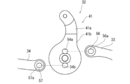
- the first steering link 33 is a member extending in the longitudinal direction, and a spherical bush 56a of the first pin member 56 covered with a self-lubricating rubber member 58 is inserted into one end portion in the longitudinal direction so that the steering lever 32. Since the spherical bush 56a has a partial spherical shape, the first steering link 33 rolls around the central point of the spherical bush 56a. In this way, the first steering link 33 is disposed between the pair of plate portions 54 and 55 of the steering lever 32, and further rotates about the action axis L2 that is the central axis of the first pin member 56. In addition, it can swing in the vehicle width direction.
- the second steering link 34 is also a member extending in the longitudinal direction, and a spherical bush 57a of the second pin member 57 in which the self-lubricating rubber member 59 is externally inserted is inserted into one end portion in the longitudinal direction.
- a spherical bush 57a has a partial spherical shape, the second steering link 34 rolls around the central point of the spherical bush 57a. In this way, the second steering link 34 is disposed between the pair of plate portions 54, 55, and further rotates about the action axis L3 that is the central axis of the second pin member 57, and in the vehicle width direction. Can also be swung.
- each of the first steering link 33 and the second steering link 34 is connected to the steering lever 32 via the two pin members 56 and 57, and is arranged so as to be separated in the vehicle vertical direction.
- the two pin members 56 and 57 in the accommodation space 43, one end portions of the first steering link 33 and the second steering link 34 are accommodated in the accommodation space 43.
- the accommodation space 43 communicates with the outside through openings 32a and 32b formed on both sides in the longitudinal direction of the accommodation portion 41b.
- the one opening 32a is formed in an obliquely upper portion on one surface in the longitudinal direction, and the first steering link 33 protrudes therefrom.
- the protruding first steering link 33 further extends to one side in the longitudinal direction through the opening 52a.
- each of the two steering links 33, 34 extends in one and the other in the longitudinal direction, and the other end portion of the first steering link 33 is the first shaft-side link receiving member 37 as shown in FIG. And the other end portion of the second steering link 34 is connected to the longitudinal beam 23F on the other longitudinal side via the second axial beam side link receiving member 38. .
- the first axial beam side link receiving member 37 is formed in an approximately L shape in a plan view, and a base end portion of the axial beam main body portion 23a of the axial beam 23B on one side in the longitudinal direction.
- the one end part is connected to the first steering link 33. Therefore, the first steering link 33 is disposed by being offset outward in the vehicle width direction with respect to the shaft beam front end portion 23 c by the first shaft beam side link receiving member 37.
- the first steering link 33 arranged in this way can be rotated in the vehicle width direction around a rotation axis L4 extending in the vehicle width direction with respect to the first axial beam side link receiving member 37. (See also FIG. 1).
- the second axial beam side link receiving member 38 is formed in an approximately L shape in plan view, and its base end is fixed to the axial beam main body portion 23a of the axial beam 23F on the other side in the longitudinal direction. One end thereof is connected to the second steering link 34. Therefore, the second steering link 34 is arranged to be offset outwardly in the vehicle width direction with respect to the shaft beam 23F by the second shaft beam side link receiving member 38.
- the second steering link 34 arranged in this way can be rotated in the vehicle width direction around a rotation axis L5 extending in the vehicle width direction with respect to the second beam-side link receiving member 38. (See also FIG. 1).
- the steering mechanism 15 configured as described above is arranged one by one on the outer side of each of the pair of side beams 21 and 21 of the carriage frame 11 in a posture as shown in FIG.
- the steering lever 32 is attached to the carriage frame 11 so that its fulcrum axis L1 extends in the vehicle width direction, and the connection point P1 that is the rotation center of the connection link 31 and the rotation of the steering lever 32
- the fulcrum P0 that is the center and the action points P2 and P3 that are the rotation centers of the two steering links 33 and 34 are arranged in a posture that is aligned in a straight line in the vehicle vertical direction.
- the steering mechanism 15 operates in conjunction with the turning operation. That is, when the pillow beam 25 and the horizontal beam 22 of the carriage frame 11 are relatively swiveled, the connecting link 31 moves in one direction (or the other) in the longitudinal direction in conjunction with the swiveling motion as shown in FIGS. To do. As a result, the curved portion 41a of the steering lever 32 is pushed in one side in the longitudinal direction (or pulled to the other side), and the steering lever 32 is rotated clockwise (or counterclockwise around the fulcrum P0 (that is, the fulcrum axis L1)). Rotate around).
- the two pin members 56 and 57 also rotate integrally with the steering lever 32 in the clockwise direction (or counterclockwise direction) about the fulcrum P0. By this turning operation, each of the two pin members 56 and 57 moves in a different direction in the longitudinal direction in plan view, and accordingly, each of the first steering link 33 and the second steering link 34 moves in the longitudinal direction. Move in different directions.
- the first steering link 33 and the second steering link 34 are mutually connected. Move away. Then, the axial beam 23B on one side in the longitudinal direction (see FIG. 2) is pushed in the longitudinal direction by the first steering link 33, and the axial beam 23F on the other side in the longitudinal direction passes through the second axial beam side link receiving member 38. The second steering link 34 is pushed to the other in the longitudinal direction. As a result, the axle boxes 13, 13 supported by the axle box support devices 14B, 14F move away from each other.
- the steering mechanism 15 configured as described above is disposed mirror-symmetrically on the outer side in the vehicle width direction of each of the pair of side beams 21 and 21, and the pair of steering mechanisms 15 includes the pillow beam 25 and the carriage frame 11.
- Move the two steering links 33 and 34 in the opposite directions That is, when the steering carriage 1 travels in a curved section and the pillow beam 25 and the carriage frame 11 are relatively turned in one turning direction, as shown in FIG.
- the lever 32 is rotated to move the first steering link 33 and the second steering link 34 away from each other.
- the two axle boxes 13 and 13 in the outer track 3a side move so that it may mutually be separated.
- the steering mechanism 15 on the inner track 3b side rotates the steering lever 32 to move the first steering link 33 and the second steering link 34 so as to approach each other.
- the two axle boxes 13 and 13 in the inner track 3b side move so that it may mutually approach.
- the attack angle of the pair of front and rear wheel shafts 12 is reduced, and steering is performed.
- the cart 1 travels smoothly in the curved section.
- the steering mechanism 15 can steer the pair of wheel shafts 12 and 12 according to the curved shape of the rail 3.
- the steering carriage 1 travels from the curved section to the straight section, the posture is returned to the original posture so that the pillow beam 25 and the cross beam 22 are parallel, and accordingly, the pair of steering mechanisms 15 moves as described above. It moves in the opposite direction. That is, the steering mechanism 15 on the outer track 3a side moves the first steering link 33 and the second steering link 34 so as to approach each other to return them to the original position, and the steering mechanism 15 on the inner track 3b side The first steering link 33 and the second steering link 34 are moved away from each other to return them to their original positions.
- the connecting point P1, the fulcrum point P0, and the action points P2 and P3 are aligned in a straight line in the vertical direction of the vehicle, and the pair of front and rear wheel shafts 12 and 12 are directed straight. Therefore, it is possible to prevent the straight traveling performance of the steering carriage 1 from being impaired in the straight section of the rail 3.
- the respective steering links 33 and 34 are arranged between the pair of shaft portions 45 and 46 that become the rotation center when the steering lever 32 rotates. That is, the pair of shaft portions 45 and 46 are disposed at positions offset in the vehicle width direction with respect to the steering links 33 and 34.
- limiting regarding a vehicle up-down direction can be decreased. That is, it is possible to increase the degree of design freedom regarding the arrangement positions of the steering links 33 and 34. Accordingly, the pair of shaft portions 45 and 46 and the steering links 33 and 34 can be arranged so as to overlap each other in a side view.
- the distance X2 between the fulcrum P0 and each of the action points P2 and P3 of the links 33 and 34. , X3 can be shortened.
- the lever ratio (the distance X1 between the fulcrum P0 and the connection point P1)
- the ratio between the distances X2 and X3 (X2: X1 and X3: X1)) is set to a predetermined ratio, for example, 1: 6 to 1: 7.
- the length of the distance X1 and the outer dimensions of the steering lever 32 are uniquely determined according to the distances X2 and X3.
- the outer dimensions of the steering lever 32 can be reduced (particularly, the height can be suppressed).
- the height of the steering mechanism 15 can be suppressed low, and the height dimension of the steering carriage 1 can be suppressed. Therefore, a low floor cart of the steering cart 1 can be realized.
- the steering mechanism 15 is formed by stacking plate-like members in the direction in which the fulcrum axis L1 extends, but the thickness of the steering mechanism 15 in the vehicle width direction is smaller than its height.
- the steering mechanism 15 by attaching the steering mechanism 15 to the carriage frame 11 so that the fulcrum axis L1 extends in the width direction, the amount of the steering mechanism 15 protruding from the carriage frame 11 in the vehicle width direction can be suppressed, and the steering carriage It is possible to suppress the length of 1 in the vehicle width direction, that is, an increase in the width.
- the steering cart 1 is configured to allow the axle box support devices 14B and 14F to tilt in the vehicle width direction with respect to the cart frame 11 as shown in FIG.
- Each of the steering links 33 and 34 also rolls on the spherical bushes 56a and 57a of the pin members 56 and 57 that are inserted therethrough, thereby moving in the vehicle width direction with respect to each of the axial beam side link receiving members 37 and 38, respectively. Tilt is allowed. That is, both the axle box support devices 14B and 14F and the steering links 33 and 34 are allowed to tilt in the vehicle width direction with respect to the carriage frame 11. Therefore, the pair of axle boxes 13 can move in the vehicle width direction, and the movement of the pair of wheel shafts 12 and 12 in the yawing direction is allowed.
- the steering links 33 and 34 can be smoothly moved with respect to the pin members 56 and 57. it can.
- the pin members 56 and 57 are fixed to the steering lever 32 so as not to rotate relative to each other, so that the pin members 56 and 57 are relative to the steering lever 32 while the steering cart 1 is traveling.
- the pin members 56 and 57 can be prevented from being worn by rotating. As a result, it is possible to prevent a backlash from occurring between the steering lever 32 and the pin members 56 and 57, thereby reducing the steering responsiveness or the steering performance.
- both end portions of the pin members 56 and 57 of the steering lever 32 and the fitting holes 54a, 54b, 55a and 55b are formed in a substantially rounded rectangular shape in a side view, and both ends of the pin members 56 and 57 are both formed.
- the pin members 56 and 57 can be fixed to the steering lever 32 so as not to be relatively rotatable by fitting the portions into the fitting holes 54a, 54b, 55a and 55b. Therefore, the assembly workability can be facilitated and the number of parts can be reduced as compared with the case where the other member such as a key is used and the relative rotation is impossible.
- the steering cart 1A of the second embodiment is similar in configuration to the steering cart 1 of the first embodiment.
- the structure different from the structure of the steering trolley 1 of 1st Embodiment is mainly demonstrated, the same code
- the steering carriage 1A of the second embodiment includes a pair of steering mechanisms 15A as shown in FIG.
- the pair of steering mechanisms 15A are provided one on each upper surface of the pair of side beams 21 and 21 so that the fulcrum axis L1 extends in the vehicle vertical direction, and each of them is mirror-symmetrical with respect to the vehicle body center line. Is arranged.
- the pair of steering mechanisms 15 ⁇ / b> A has the same configuration as the steering mechanism 15 of the first embodiment, and the connection link 31 is connected to the pillow beam side link receiver 35 ⁇ / b> A of the pillow beam 25.
- each steering mechanism 15A is attached to the carriage frame 11 in such a posture that the connection point P1, the fulcrum P0, and the action points P2 and P3 are aligned in the vehicle width direction.
- the distance X2 (distance between P0 and P2) and X3 (distance between P0 and P3) of the steering mechanism 15A can be shortened, so that the outer dimensions of the steering lever 32 are reduced. (In particular, the height can be suppressed). Thereby, the width of the steering mechanism 15A can be reduced, and the width dimension of the steering carriage 1A can be reduced. Further, the steering mechanism 15A is configured such that plate-like members are stacked in the direction in which the fulcrum axis L1 extends, but the height of the steering mechanism 15A is smaller than its width.
- the steering mechanism 15A by attaching the steering mechanism 15A to the carriage frame 11 so that the fulcrum axis L1 extends in the vehicle vertical direction, the amount of the steering mechanism 15A protruding from the carriage frame 11 in the vehicle vertical direction can be suppressed. Thereby, the height of the steering cart 1A can be lowered.
- the steering carriage 1A has the same effects as the steering carriage 1 of the first embodiment.
- the steering carts 1 and 1A of the first and second embodiments are bolster-equipped carts having the pillow beam 25, it is not always necessary to have the pillow beam 25. That is, the steering carts 1 and 1A may be bolsterless carts.
- the connection link 31 of the steering mechanisms 15 and 15A is rotatably connected to a link receiving member that protrudes downward from the lower surface of the vehicle body 4.
- the connecting link 31 moves in one direction and the other in the longitudinal direction, and the steering mechanisms 15 and 15A operate.
- both the front and rear wheel shafts 12 and 12 are steered by the steering mechanism 15, but it is not always necessary to steer both the wheel shafts 12 and 12.
- the structure may be such that either the front or rear wheel axle 12 is steered by the mechanisms 15 and 15A.
- the pair of shaft portions 45 and 46 are formed on the steering lever 32 of the steering mechanisms 15 and 15A as the rotation center member, but the rotation center is not necessarily required.
- the member does not need to be a pair of shaft portions 45 and 46.
- each of the pair of shaft portions 51b and 53b is formed on the rear box 51B and the box lid 53B, and the surface of the lid body 42 of the steering lever 32 and the back surface of the accommodating portion 41b are formed.
- the insertion grooves 45B and 46B may be formed as the rotation center member.
- the shaft portions 45 and 46 are formed on both sides of the steering lever 32 in the axial direction, but on the one side surface of the steering lever 32 in the axial direction.
- the rotation center member (the shaft portion 45 or the insertion groove 45B) may not be formed.
- the shaft portions 45 and 46 and the steering links 33 and 34 are arranged so as to overlap each other in a side view, but at least one of the steering links 33 and Only 34 may be arranged so as to overlap the shaft portions 45 and 46.
- the steering links 33 and 34 can be designed by offsetting the shaft portions 45 and 46 with respect to the steering links 33 and 34 without overlapping the steering links 33 and 34 with the shaft portions 45 and 46.
- the effect of improving the degree of freedom can be achieved.
- the cart 1 may be configured to use a leaf spring instead of the side beam 21 and the shaft spring 24.
- the spring receiving portions of the pair of front and rear axle boxes 13 and 13 support the ends on both sides in the longitudinal direction of the leaf springs from below, respectively, and the center portion in the longitudinal direction of the leaf springs supports the cross beam 22 from below. Good.
Landscapes
- Engineering & Computer Science (AREA)
- Mechanical Engineering (AREA)
- Vehicle Body Suspensions (AREA)
- Steering-Linkage Mechanisms And Four-Wheel Steering (AREA)
- Handcart (AREA)
- Platform Screen Doors And Railroad Systems (AREA)
Abstract
Description
図1に示す鉄道車両2は、地面等に敷設されたレール3を走行するようになっており、車体4と操舵台車1とを備えている。車体4は、レール方向に長い大略箱状に形成されており、その中に乗客又は荷役等を収容するようになっている。車体4の下方には、操舵台車1が配置されており、操舵台車1は、空気ばね5を介して車体4を下方から支持している。以下では、操舵台車1の構成について詳しく説明する。
操舵台車1は、図1及び図2に示すように台車枠11、及び前後一対の輪軸12を備えている。台車枠11は、一対の側梁21,21と、横梁22とを有している。一対の側梁21,21は、車体4の長手方向(即ち、車両長手方向であり、以下、「長手方向」という)に延在する部材であり、平行且つ車体4の車幅方向(以下、「車幅方向」ともいう)に離して配置されている。横梁22は、一対の側梁21,21の中央部分に架け渡すように一体的に設けられており、台車枠11は、平面視でH字状に形成されている(図2参照)。このように構成されている台車枠11には、一対の輪軸12,12が長手方向に離間し且つ平行に配置されている。
図2に示すように、一対の操舵機構15は、台車枠11の一対の側梁21,21の各々に1つずつ設けられており、各々は車体中心線に対して鏡面対称に配置されている。なお、図2では、一対の側梁21,21の長手方向両端部を切断して操舵台車1を示している。一対の各操舵機構15は、同様の構成を有しており、図3及び図4に示すように連結リンク31と、操舵テコ32と、第1操舵リンク33と、第2操舵リンク34とを有している。連結リンク31は、略長手方向に延在する部材である。図1に示すように連結リンク31の長手方向一端部は、枕梁側リンク受部材35を介して枕梁25に連結されている。また、連結リンク31の長手方向一端部は、車両上下方向に対して相対回動可能に枕梁側リンク受部材35に取付けられており、枕梁25と台車枠11の横梁22との相対旋回動作に連動して長手方向に動くようになっている。また、連結リンク31の長手方向他端部は、操舵テコ32に連結されている。
曲線区間において枕梁25と台車枠11とが相対旋回すると、操舵機構15は、その旋回動作に連動して作動する。即ち、枕梁25と台車枠11の横梁22とが相対旋回すると、図8(b)及び(c)に示すように旋回動作に連動して連結リンク31が長手方向一方(又は他方)に移動する。これにより、操舵テコ32の湾曲部41aが長手方向一方に押され(又は他方に引かれ)て、操舵テコ32が支点P0(即ち、支点軸線L1)を中心に時計回り方向(又は、反時計周り方向)に回動する。2つのピン部材56,57もまた操舵テコ32と一体となって支点P0を中心に時計回り方向(又は、反時計周り方向)に回動する。この回動動作により、2つのピン部材56,57の各々が平面視で長手方向の互いに異なる方向に移動し、それに伴って第1操舵リンク33及び第2操舵リンク34の各々が長手方向に互いに異なる方向に移動する。
第2実施形態の操舵台車1Aは、第1実施形態の操舵台車1と構成が類似している。以下では、第2実施形態の操舵台車1Aの構成について、第1実施形態の操舵台車1の構成と異なる構成について主に説明し、同一の構成については同一の符号を付して説明を省略する。
第1及び第2実施形態の操舵台車1,1Aは、枕梁25を有するボルスタ付き台車であったが、必ずしも枕梁25を有している必要はない。即ち、操舵台車1,1Aは、ボルスタレス台車であってもよい。その場合、操舵機構15、15Aの連結リンク31は、車体4の下面から下方に突出するリンク受部材に回動可能に連結される。これにより、台車枠11に対する車体4の旋回動作に連動して連結リンク31が長手方向一方及び他方に移動し、操舵機構15,15Aが作動する。また、第1及び第2実施形態の操舵台車1,1Aでは、操舵機構15によって前後両方の輪軸12,12を操舵しているが、必ずしも両方の輪軸12,12を操舵する必要はなく、操舵機構15、15Aによって前後何れかの輪軸12を操舵するような構成であってもよい。
2 鉄道車両
4 車体
11 台車枠
12 輪軸
13 軸箱
14 軸箱支持装置
15 操舵機構
16 車軸
17 車輪
23 軸梁
23a 軸梁本体部
23b 基端部
23c 軸梁先端部
24 軸ばね
25 枕梁(ボルスタ)
31 連結リンク
32 操舵テコ
32a,32b 開口
33 第1操舵リンク
34 第2操舵リンク
37 第1軸梁側リンク受
38 第2軸梁側リンク受
45 軸部(回転中心部材)
45B 挿通溝部(回転中心部材)
46 軸部(回転中心部材)
46B 挿通溝部(回転中心部材)
49 ハウジング
52a 開口
52b 開口
54 プレート部
55 プレート部
56 第1ピン部材
56a 球面ブッシュ
57 第2ピン部材
57a 球面ブッシュ
L1 支点軸線
Claims (9)
- 車体又はボルスタを鉛直軸線回りに相対旋回可能に支持する台車枠と、
車軸及び一対の車輪を有する2つの輪軸と、
前記車軸を支持する軸受が収容された軸箱を台車枠に連結する軸梁を有する軸箱支持装置と、
前記車体又はボルスタの相対旋回に応じて前記2つの輪軸のうち少なくとも一方を操舵する操舵機構とを備え、
前記操舵機構は、
前記台車枠に対して支点軸線を中心に回動する操舵テコと、
前記車体又はボルスタと前記操舵テコとを連結し、前記台車枠と前記車体又はボルスタとの相対旋回に連動する連結リンクと、
前記操舵テコと前記軸梁とを連結し、前記操舵テコの回動動作に連動して前記軸梁を介して前記軸箱を変位させることにより前記輪軸を操舵する少なくとも1つの操舵リンクとを有し、
前記操舵テコは、支点軸線まわりに回動する軸部又は溝部である回動中心部材を有し、
前記回動中心部材は、前記操舵リンクに対して軸線方向にオフセットした位置に配置されている、鉄道車両用操舵台車。 - 前記操舵リンクと前記操舵テコの回動中心部材は、前記軸線方向に見て部分的に重なり合うよう配置されている、請求項1に記載の鉄道車両用操舵台車。
- 前記操舵機構は、前記台車枠に固定され且つ前記操舵テコの少なくとも一部分を覆うハウジングを有し、
前記操舵テコは、前記回動中心部材に対して前記軸線方向に離間し、前記操舵リンクを挟んだ位置に配置されているもう1つの回動中心部材を有し、
前記一対の回動中心部材の各々は、前記ハウジングに回動可能に設けられている、請求項1又は2に記載の鉄道車両用操舵台車。 - 前記操舵テコは、
前記一対の回動中心部材の各々が形成された一対のプレートと、
前記一対のプレートの間に前記軸線方向に架け渡すように前記一対のプレートに設けられ、球面ブッシュを含むピン部材とを有し、
前記操舵リンクは、前記ピン部材の球面ブッシュに転動可能に設けられている、請求項3に記載の鉄道車両用操舵台車。 - 前記少なくとも1つの操舵リンクは、車両長手方向一方側に延びて前記車両長手方向一方側にある前記軸箱支持装置に連結される第1操舵リンクと、他方側に延びて前記車両長手方向他方側にある前記軸箱支持装置に連結される第2の操舵リンクとを有し、
前記第1及び第2操舵リンクの一端部は、前記操舵テコの前記支点軸線に垂直な方向に離間させて配置され、且つ前記ピン部材を介して前記操舵テコに連結されている、請求項4に記載の鉄道車両用操舵台車。 - 前記操舵テコは、前記軸線方向に見て円形状の収容部を有しており、
前記収容部は、その中に形成される収容空間と、前記車両長手方向一方及び他方に開口する2つの開口とを有し、
前記第1及び第2操舵リンクは、その一端部が前記収容空間に収容され、且つ前記2つの開口の各々から前記車両長手方向一方及び他方に向かって突き出ている、請求項5に記載の鉄道車両用操舵台車。 - 前記操舵テコは、その前記支点軸線が車幅方向に延在するように配置され、
前記連結リンク及び前記操舵リンクは、前記車幅方向から見て車両上下方向に並べて配置されている、請求項1乃至6の何れか1つに記載の鉄道車両用操舵台車。 - 前記操舵機構は、前記操舵テコの前記支点軸線が車両上下方向に延在するように配置され、
前記連結リンク及び前記操舵リンクは、前記車両上下方向から見て車幅方向に並べて配置されている、請求項1乃至6の何れか1つに記載の鉄道車両用操舵台車。 - 前記軸梁は、
前記車両長手方向に延びる軸梁本体部と、
前記軸梁本体部の先端から前記車両長手方向に延びて前記台車枠に連結される軸梁先端部と、
前記軸梁本体部から延び、前記軸梁先端部に対して車幅方向にオフセットした位置において前記操舵リンクが連結されるリンク受部とを有し、
前記車体又はボルスタの相対旋回に応じて、前記操舵リンクが動くことによって前記軸梁を前記車両長手方向に変位させて、前記輪軸を操舵する、請求項1乃至6の何れか1つに記載の鉄道車両用操舵台車。
Priority Applications (3)
| Application Number | Priority Date | Filing Date | Title |
|---|---|---|---|
| SG11201803536PA SG11201803536PA (en) | 2015-10-29 | 2016-10-20 | Railcar steering bogie |
| CN201680059034.5A CN108137067B (zh) | 2015-10-29 | 2016-10-20 | 铁道车辆用导向转向架 |
| US15/772,111 US10730533B2 (en) | 2015-10-29 | 2016-10-20 | Railcar steering bogie |
Applications Claiming Priority (2)
| Application Number | Priority Date | Filing Date | Title |
|---|---|---|---|
| JP2015212678A JP6577834B2 (ja) | 2015-10-29 | 2015-10-29 | 鉄道車両用操舵台車 |
| JP2015-212678 | 2015-10-29 |
Publications (1)
| Publication Number | Publication Date |
|---|---|
| WO2017073441A1 true WO2017073441A1 (ja) | 2017-05-04 |
Family
ID=58630136
Family Applications (1)
| Application Number | Title | Priority Date | Filing Date |
|---|---|---|---|
| PCT/JP2016/081045 Ceased WO2017073441A1 (ja) | 2015-10-29 | 2016-10-20 | 鉄道車両用操舵台車 |
Country Status (6)
| Country | Link |
|---|---|
| US (1) | US10730533B2 (ja) |
| JP (1) | JP6577834B2 (ja) |
| CN (1) | CN108137067B (ja) |
| SG (1) | SG11201803536PA (ja) |
| TW (1) | TWI635010B (ja) |
| WO (1) | WO2017073441A1 (ja) |
Families Citing this family (3)
| Publication number | Priority date | Publication date | Assignee | Title |
|---|---|---|---|---|
| JP6577834B2 (ja) * | 2015-10-29 | 2019-09-18 | 川崎重工業株式会社 | 鉄道車両用操舵台車 |
| JP6506676B2 (ja) * | 2015-10-29 | 2019-04-24 | 川崎重工業株式会社 | 鉄道車両用台車の軸箱支持装置 |
| JP6506677B2 (ja) * | 2015-10-29 | 2019-04-24 | 川崎重工業株式会社 | 鉄道車両用操舵台車 |
Citations (5)
| Publication number | Priority date | Publication date | Assignee | Title |
|---|---|---|---|---|
| JPH08198108A (ja) * | 1995-01-31 | 1996-08-06 | Hitachi Ltd | 鉄道車両用台車 |
| JPH10226333A (ja) * | 1997-02-17 | 1998-08-25 | Hitachi Ltd | 鉄道車両用操舵台車 |
| JP2005262957A (ja) * | 2004-03-17 | 2005-09-29 | Railway Technical Res Inst | 鉄道車両用アシスト操舵台車 |
| EP2517943A1 (en) * | 2009-12-24 | 2012-10-31 | Korea Railroad Research Institute | Active steering control device and method for railroad vehicle |
| JP2013023094A (ja) * | 2011-07-21 | 2013-02-04 | Nippon Steel & Sumitomo Metal Corp | 鉄道車両用操舵台車 |
Family Cites Families (25)
| Publication number | Priority date | Publication date | Assignee | Title |
|---|---|---|---|---|
| US3948188A (en) * | 1970-06-05 | 1976-04-06 | Swiss Aluminium Ltd. | Resilient railway bogie |
| DE3725574A1 (de) * | 1987-08-01 | 1989-02-16 | Messerschmitt Boelkow Blohm | Fahrwerk fuer ein schienenfahrzeug |
| DE3826010A1 (de) * | 1987-08-14 | 1989-02-23 | South African Inventions | Fahrgestell |
| JP2724944B2 (ja) | 1992-09-10 | 1998-03-09 | 株式会社日立製作所 | 操舵台車 |
| JP3394151B2 (ja) | 1997-03-26 | 2003-04-07 | 財団法人鉄道総合技術研究所 | 鉄道車両用操舵台車 |
| JPH11124033A (ja) * | 1997-10-23 | 1999-05-11 | Fuji Heavy Ind Ltd | 鉄道車両用操舵台車 |
| FR2862935B1 (fr) * | 2003-12-02 | 2006-03-03 | Alstom | Dispositif de liaison souple entre un longeron et une boite d'essieu |
| GB0500236D0 (en) * | 2005-01-07 | 2005-02-16 | Wagon Rail Interface Technolog | Railway bogies |
| CN100393565C (zh) * | 2006-12-01 | 2008-06-11 | 西南交通大学 | 独立轮对两轴转向架铰接车迫导向机构 |
| WO2009063569A1 (ja) * | 2007-11-16 | 2009-05-22 | Kawasaki Jukogyo Kabushiki Kaisha | 低床式鉄道車両用台車及びそれを備えた低床式鉄道車両 |
| CN201151401Y (zh) * | 2007-12-27 | 2008-11-19 | 南车南京浦镇车辆有限公司 | 客车转向架径向导向装置 |
| EP2733041B1 (en) * | 2011-07-14 | 2019-09-11 | Kawasaki Jukogyo Kabushiki Kaisha | Railway vehicle truck |
| JP5828235B2 (ja) | 2011-07-21 | 2015-12-02 | 新日鐵住金株式会社 | 鉄道車両用操舵台車 |
| WO2013061641A1 (ja) * | 2011-10-26 | 2013-05-02 | 新日鐵住金株式会社 | 鉄道車両用台車の操舵方法及び装置並びに台車 |
| JP5918681B2 (ja) * | 2012-10-04 | 2016-05-18 | 株式会社日立製作所 | 鉄道車両用台車 |
| CN203593001U (zh) * | 2013-12-13 | 2014-05-14 | 齐齐哈尔轨道交通装备有限责任公司 | 一种高速铁路货车转向架 |
| JP6506677B2 (ja) * | 2015-10-29 | 2019-04-24 | 川崎重工業株式会社 | 鉄道車両用操舵台車 |
| JP6577834B2 (ja) * | 2015-10-29 | 2019-09-18 | 川崎重工業株式会社 | 鉄道車両用操舵台車 |
| JP6595904B2 (ja) * | 2015-12-25 | 2019-10-23 | 川崎重工業株式会社 | 鉄道車両用軸箱及びその製造方法 |
| CN105460041B (zh) * | 2016-01-04 | 2017-10-27 | 西南交通大学 | 一种转向架迫导向机构 |
| JP6718237B2 (ja) * | 2016-01-14 | 2020-07-08 | 川崎重工業株式会社 | ブレーキユニットを備えた鉄道車両用操舵台車 |
| JP6774314B2 (ja) * | 2016-11-24 | 2020-10-21 | 川崎重工業株式会社 | 鉄道車両用台車 |
| JP6726612B2 (ja) * | 2016-12-16 | 2020-07-22 | 川崎重工業株式会社 | 鉄道車両用台車 |
| JP6767889B2 (ja) * | 2017-01-30 | 2020-10-14 | 川崎重工業株式会社 | 鉄道車両の軸箱支持装置 |
| JP6751361B2 (ja) * | 2017-01-30 | 2020-09-02 | 川崎重工業株式会社 | 鉄道車両用台車 |
-
2015
- 2015-10-29 JP JP2015212678A patent/JP6577834B2/ja active Active
-
2016
- 2016-10-20 CN CN201680059034.5A patent/CN108137067B/zh active Active
- 2016-10-20 WO PCT/JP2016/081045 patent/WO2017073441A1/ja not_active Ceased
- 2016-10-20 US US15/772,111 patent/US10730533B2/en active Active
- 2016-10-20 SG SG11201803536PA patent/SG11201803536PA/en unknown
- 2016-10-26 TW TW105134539A patent/TWI635010B/zh active
Patent Citations (5)
| Publication number | Priority date | Publication date | Assignee | Title |
|---|---|---|---|---|
| JPH08198108A (ja) * | 1995-01-31 | 1996-08-06 | Hitachi Ltd | 鉄道車両用台車 |
| JPH10226333A (ja) * | 1997-02-17 | 1998-08-25 | Hitachi Ltd | 鉄道車両用操舵台車 |
| JP2005262957A (ja) * | 2004-03-17 | 2005-09-29 | Railway Technical Res Inst | 鉄道車両用アシスト操舵台車 |
| EP2517943A1 (en) * | 2009-12-24 | 2012-10-31 | Korea Railroad Research Institute | Active steering control device and method for railroad vehicle |
| JP2013023094A (ja) * | 2011-07-21 | 2013-02-04 | Nippon Steel & Sumitomo Metal Corp | 鉄道車両用操舵台車 |
Also Published As
| Publication number | Publication date |
|---|---|
| JP6577834B2 (ja) | 2019-09-18 |
| SG11201803536PA (en) | 2018-05-30 |
| TWI635010B (zh) | 2018-09-11 |
| CN108137067A (zh) | 2018-06-08 |
| CN108137067B (zh) | 2020-04-24 |
| US20180319411A1 (en) | 2018-11-08 |
| JP2017081442A (ja) | 2017-05-18 |
| US10730533B2 (en) | 2020-08-04 |
| TW201718299A (zh) | 2017-06-01 |
Similar Documents
| Publication | Publication Date | Title |
|---|---|---|
| US10131367B2 (en) | Steering bogie, and vehicle for track-based transportation system | |
| US10065663B2 (en) | Steering bogie and vehicle | |
| KR20110030500A (ko) | 연결 부재를 포함하는 모노레일 대차 조립체 | |
| JP6273096B2 (ja) | 鉄道車両用台車 | |
| JPWO2009038068A1 (ja) | 鉄道車両用操舵台車、鉄道車両および連接車両 | |
| WO2017073442A1 (ja) | 鉄道車両用操舵台車 | |
| JP6577834B2 (ja) | 鉄道車両用操舵台車 | |
| JP2014073748A (ja) | 鉄道車両用台車 | |
| US9919720B2 (en) | Bogie and track-type vehicle | |
| JPH02212263A (ja) | 鉄道車両用台車 | |
| JP6620007B2 (ja) | 鉄道車両用操舵台車 | |
| JP5331045B2 (ja) | 鉄道車両用台車 | |
| JP7319550B2 (ja) | 鉄道車両用のリンク装置及び台車 | |
| JP5180143B2 (ja) | 鉄道車両用台車 | |
| JP6426997B2 (ja) | 鉄道車両用の操舵台車 | |
| JP6510807B2 (ja) | 鉄道車両用の操舵台車 | |
| JP5562882B2 (ja) | 鉄道車両 | |
| EP3546313A1 (en) | Yawing suppression device for railway vehicle and railway vehicle including same | |
| JPS6076464A (ja) | 鉄道車両用電動台車 |
Legal Events
| Date | Code | Title | Description |
|---|---|---|---|
| 121 | Ep: the epo has been informed by wipo that ep was designated in this application |
Ref document number: 16859671 Country of ref document: EP Kind code of ref document: A1 |
|
| WWE | Wipo information: entry into national phase |
Ref document number: 11201803536P Country of ref document: SG |
|
| WWE | Wipo information: entry into national phase |
Ref document number: 15772111 Country of ref document: US |
|
| NENP | Non-entry into the national phase |
Ref country code: DE |
|
| 122 | Ep: pct application non-entry in european phase |
Ref document number: 16859671 Country of ref document: EP Kind code of ref document: A1 |