WO2017072992A1 - シリンジ型噴出器 - Google Patents
シリンジ型噴出器 Download PDFInfo
- Publication number
- WO2017072992A1 WO2017072992A1 PCT/JP2016/003784 JP2016003784W WO2017072992A1 WO 2017072992 A1 WO2017072992 A1 WO 2017072992A1 JP 2016003784 W JP2016003784 W JP 2016003784W WO 2017072992 A1 WO2017072992 A1 WO 2017072992A1
- Authority
- WO
- WIPO (PCT)
- Prior art keywords
- syringe
- shaft member
- pressing
- elastic piece
- type ejector
- Prior art date
- Legal status (The legal status is an assumption and is not a legal conclusion. Google has not performed a legal analysis and makes no representation as to the accuracy of the status listed.)
- Ceased
Links
Images






Classifications
-
- A—HUMAN NECESSITIES
- A61—MEDICAL OR VETERINARY SCIENCE; HYGIENE
- A61M—DEVICES FOR INTRODUCING MEDIA INTO, OR ONTO, THE BODY; DEVICES FOR TRANSDUCING BODY MEDIA OR FOR TAKING MEDIA FROM THE BODY; DEVICES FOR PRODUCING OR ENDING SLEEP OR STUPOR
- A61M5/00—Devices for bringing media into the body in a subcutaneous, intra-vascular or intramuscular way; Accessories therefor, e.g. filling or cleaning devices, arm-rests
- A61M5/178—Syringes
- A61M5/31—Details
- A61M5/315—Pistons; Piston-rods; Guiding, blocking or restricting the movement of the rod or piston; Appliances on the rod for facilitating dosing ; Dosing mechanisms
- A61M5/31565—Administration mechanisms, i.e. constructional features, modes of administering a dose
- A61M5/31566—Means improving security or handling thereof
-
- A—HUMAN NECESSITIES
- A61—MEDICAL OR VETERINARY SCIENCE; HYGIENE
- A61M—DEVICES FOR INTRODUCING MEDIA INTO, OR ONTO, THE BODY; DEVICES FOR TRANSDUCING BODY MEDIA OR FOR TAKING MEDIA FROM THE BODY; DEVICES FOR PRODUCING OR ENDING SLEEP OR STUPOR
- A61M5/00—Devices for bringing media into the body in a subcutaneous, intra-vascular or intramuscular way; Accessories therefor, e.g. filling or cleaning devices, arm-rests
- A61M5/178—Syringes
- A61M5/31—Details
- A61M5/315—Pistons; Piston-rods; Guiding, blocking or restricting the movement of the rod or piston; Appliances on the rod for facilitating dosing ; Dosing mechanisms
-
- A—HUMAN NECESSITIES
- A61—MEDICAL OR VETERINARY SCIENCE; HYGIENE
- A61M—DEVICES FOR INTRODUCING MEDIA INTO, OR ONTO, THE BODY; DEVICES FOR TRANSDUCING BODY MEDIA OR FOR TAKING MEDIA FROM THE BODY; DEVICES FOR PRODUCING OR ENDING SLEEP OR STUPOR
- A61M5/00—Devices for bringing media into the body in a subcutaneous, intra-vascular or intramuscular way; Accessories therefor, e.g. filling or cleaning devices, arm-rests
- A61M5/178—Syringes
- A61M5/31—Details
- A61M5/315—Pistons; Piston-rods; Guiding, blocking or restricting the movement of the rod or piston; Appliances on the rod for facilitating dosing ; Dosing mechanisms
- A61M5/31511—Piston or piston-rod constructions, e.g. connection of piston with piston-rod
-
- A—HUMAN NECESSITIES
- A61—MEDICAL OR VETERINARY SCIENCE; HYGIENE
- A61M—DEVICES FOR INTRODUCING MEDIA INTO, OR ONTO, THE BODY; DEVICES FOR TRANSDUCING BODY MEDIA OR FOR TAKING MEDIA FROM THE BODY; DEVICES FOR PRODUCING OR ENDING SLEEP OR STUPOR
- A61M5/00—Devices for bringing media into the body in a subcutaneous, intra-vascular or intramuscular way; Accessories therefor, e.g. filling or cleaning devices, arm-rests
- A61M5/178—Syringes
- A61M5/31—Details
- A61M5/315—Pistons; Piston-rods; Guiding, blocking or restricting the movement of the rod or piston; Appliances on the rod for facilitating dosing ; Dosing mechanisms
- A61M5/31565—Administration mechanisms, i.e. constructional features, modes of administering a dose
- A61M5/3159—Dose expelling manners
-
- A—HUMAN NECESSITIES
- A61—MEDICAL OR VETERINARY SCIENCE; HYGIENE
- A61M—DEVICES FOR INTRODUCING MEDIA INTO, OR ONTO, THE BODY; DEVICES FOR TRANSDUCING BODY MEDIA OR FOR TAKING MEDIA FROM THE BODY; DEVICES FOR PRODUCING OR ENDING SLEEP OR STUPOR
- A61M5/00—Devices for bringing media into the body in a subcutaneous, intra-vascular or intramuscular way; Accessories therefor, e.g. filling or cleaning devices, arm-rests
- A61M5/178—Syringes
- A61M5/31—Details
- A61M5/315—Pistons; Piston-rods; Guiding, blocking or restricting the movement of the rod or piston; Appliances on the rod for facilitating dosing ; Dosing mechanisms
- A61M5/31565—Administration mechanisms, i.e. constructional features, modes of administering a dose
- A61M5/3159—Dose expelling manners
- A61M5/31593—Multi-dose, i.e. individually set dose repeatedly administered from the same medicament reservoir
- A61M5/31595—Pre-defined multi-dose administration by repeated overcoming of means blocking the free advancing movement of piston rod, e.g. by tearing or de-blocking
-
- A—HUMAN NECESSITIES
- A61—MEDICAL OR VETERINARY SCIENCE; HYGIENE
- A61M—DEVICES FOR INTRODUCING MEDIA INTO, OR ONTO, THE BODY; DEVICES FOR TRANSDUCING BODY MEDIA OR FOR TAKING MEDIA FROM THE BODY; DEVICES FOR PRODUCING OR ENDING SLEEP OR STUPOR
- A61M5/00—Devices for bringing media into the body in a subcutaneous, intra-vascular or intramuscular way; Accessories therefor, e.g. filling or cleaning devices, arm-rests
- A61M5/50—Devices for bringing media into the body in a subcutaneous, intra-vascular or intramuscular way; Accessories therefor, e.g. filling or cleaning devices, arm-rests having means for preventing re-use, or for indicating if defective, used, tampered with or unsterile
- A61M5/5013—Means for blocking the piston or the fluid passageway to prevent illegal refilling of a syringe
Definitions
- the present invention relates to a syringe type ejector including a syringe and a plunger that can be pushed into the syringe, and relates to a technique for pushing the plunger in a stepwise manner.
- Some syringe-type ejectors for example, push out a plunger into a syringe and take out contents such as a chemical (for example, see Patent Document 1).
- Patent Document 2 discloses a syringe-type ejector capable of ejecting the contents in two steps by pushing the plunger in two stages.
- An object of the present invention is to provide a syringe type ejector that can divide the contents into small portions and improve operability.
- a syringe-type ejector comprising a syringe and a plunger that can be pushed into the syringe,
- the plunger has a first shaft member having a piston at a tip thereof, and a second shaft member fitted into a cylindrical portion of the first shaft member,
- the first shaft member has at least one elastic piece extending rearward, and the elastic piece is slidable to enter the rear end opening of the syringe and slide on the inner peripheral surface of the syringe.
- the second shaft member has a pressing shaft that fits into the cylindrical portion, and an end surface that presses the free end of the elastic piece is provided at a tip of the pressing shaft, and an outer peripheral surface of the pressing shaft is provided on the outer peripheral surface of the pressing shaft.
- An engagement protrusion is provided that engages with the locking portion of the cylindrical portion to prevent the cylindrical portion from coming off,
- the free end of the elastic piece is restrained with the syringe by pressing from the end surface, thereby causing the elastic piece to bend and deform from the sliding protrusion as a starting point. Lock it to the rear edge, By the relaxation of the pressing, the locking projection is unlocked by a restoring force starting from the sliding projection of the bending deformation.
- an opening penetrating in the radial direction is provided in the cylindrical portion, the elastic piece is disposed in the opening, and a rear end edge of the opening is the locking portion.
- the position of the end surface when the pressing is relieved is determined by the engagement protrusion coming into contact with the locking portion of the cylindrical portion.
- the sliding protrusion and the locking protrusion are connected by a thin portion having a thin radial thickness.
- the elastic piece is formed so that the thickness in the radial direction gradually increases from the base to the sliding protrusion.
- a tapered surface is formed on the end surface.
- a rib that engages with a rear end of the syringe at the pressing start position is provided on the outer peripheral surface of the first shaft member.
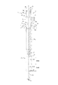
- FIG. 1 is a cross-sectional view taken along the line AA of a plunger used in a syringe-type ejector in an initial state before the operation of the syringe-type ejector according to an embodiment of the present invention.
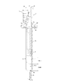
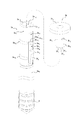
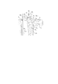
- FIG. 6A It is a front half sectional view of the 2nd shaft member used for the syringe type ejector which is one embodiment of the present invention. It is a perspective view of the 1st shaft member and the 2nd shaft member which comprise the plunger used for the syringe type ejector which is one Embodiment of this invention. It is a front fragmentary sectional view which shows the state which the 1st ejection by the syringe type ejector which is one Embodiment of this invention was completed. It is an enlarged view of the flange part in FIG. 6A.
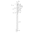
- FIG. 7A It is a front fragmentary sectional view which shows the state which the preparation of the 2nd ejection by the syringe type ejector which is one Embodiment of this invention was completed. It is an enlarged view of the flange part in FIG. 7A.
- symbol 2 is a syringe which can be filled with the contents C, such as a chemical
- the direction in which the contents C are ejected is the front side, and the side where the second shaft member 3b is located (upward direction in FIG. 1B) ) Is the rear.
- the syringe 2 has a hollow barrel portion 2a, and a distal end portion 2c is integrally connected to the barrel portion 2a via a shoulder portion 2b.
- the distal end portion 2c has a smaller diameter than the body portion 2a.
- the flange portion 2d is attached to the syringe rear end 2d 0. That is, the flange portion 2d constitutes the rear end of the syringe 2.
- Numeral 3 is a plunger accommodated in the syringe 2.
- the plunger 3 includes a first shaft member 3a and a second shaft member 3b disposed behind the first shaft member 3a.
- the first shaft member 3 a is provided with a piston 4 at a tip portion accommodated in the syringe 2.
- the piston 4 is made of an elastic material such as rubber, and is slidably held on the inner peripheral surface 2f of the syringe barrel 2a.
- a space R is formed between the syringe 2 and the piston 4.
- the space R is filled with the contents C.
- the contents C filled in the space R are pressure-fed into the tip through hole A 1 formed in the tip 2c by pushing the plunger 3 in.
- a cylindrical portion 3a 9 is provided near the rear of the first shaft member 3a.
- the opening 3a 8 is provided in the peripheral wall of the cylindrical portion 3a 9 penetrating in the radial direction.
- the opening 3a 8 communicates with the cylindrical portion insertion hole 3a 10 into which the second shaft member 3b is inserted.
- the first shaft member 3a is integrally provided with two elastic pieces 3a 1 extending rearward.
- the elastic piece 3a 1 is provided with a sliding projection 3a 2 and a locking projection 3a 3 .
- the sliding projection 3a 2 and the locking projection 3a 3 are provided in the order of the sliding projection 3a 2 and the locking projection 3a 3 with an interval rearward along the axis O.
- the sliding protrusion 3a 2 has a tapered portion 3f 0 that is tapered toward the tip. Thereby, the sliding protrusion 3a 2 enters from the rear end opening A 2 of the syringe 2 and can slide on the inner peripheral surface 2f of the syringe 2, so that the plunger 3 is allowed to be pushed in.
- the sliding projection 3a 2 and the locking projection 3a 3 are connected by a thin portion 3a 6 so that the elastic piece 3a 1 is easily bent and deformed with the sliding projection 3a 2 as a starting point.
- the locking protrusion 3a 3 is caught by the inner peripheral end of the flange portion 2d provided at the rear end of the syringe 2 to prevent the plunger 3 from being pushed.
- the elastic piece 3 a 1 is disposed so as to be accommodated in the opening 3 a 8 . 1B, the outer diameter of the sliding protrusion 3a 2 in the initial state (initial position) is formed larger than the inner diameter of the syringe 2.
- the first shaft member 3a has a base portion 3a 4 for fixing the piston 4 , and the elastic pieces 3a 1 are connected to the rear ends of the base portions 3a 4 respectively.
- the base 3 a 4 has two wall surfaces extending in the front-rear direction (vertical direction in FIG. 5) so as to have a cross-sectional shape between the disk-shaped front wall and rear wall.
- intersect at right angles in the center can be employ
- the elastic piece 3a 1 can be deformed so that the free end side on which the locking projection 3a 3 is provided can be deformed and restored with the connecting portion with the base 3a 4 as a fixed end.
- a hollow cylindrical tube portion 3a 9 is connected to the rear end of the base portion 3a 4 .
- the locking protrusion 3a 3 is integrally formed on the free end side of the elastic piece 3a 1 . Further, as shown in FIGS. 3 and 5, the rear end surface of the locking projection 3a 3 is formed as a pressure receiving surface 3a 7 that receives a pressing force from the second shaft member 3b.
- the pressure-receiving taper surface 3a 71 has a taper surface whose outer circumferential direction is slightly inclined forward.
- the pressure receiving horizontal surface 3a 70 functions as a surface that receives the pressing force from the second shaft member 3b in the first ejection of the contents C.
- the pressure-receiving taper surface 3a 71 functions as a surface that receives the pressing force from the second shaft member 3b in the second ejection of the contents C.
- ribs 3a 12 are provided on the outer surface of the cylindrical portion 3a 9 at two locations in the front-rear direction (two locations in the vertical direction in FIG. 2).
- the front rib 3a 12 is provided so as to engage with the inner peripheral end of the flange portion 2d at the position of the plunger 3 where the first ejection of the contents C is started.
- the rear rib 3a 12 is provided so as to engage with the inner peripheral end of the flange portion 2d at the position of the plunger 3 where the second ejection of the contents C is started.
- the user of the syringe-type ejector 1 orients the distal end through hole A 1 with respect to the ejection target at a position where the rib 3a 12 engages with the inner peripheral end of the flange portion 2d. Then, when the user presses the plunger 3, the rib 3a 12 gets over the inner peripheral end of the flange portion 2d, and the contents C can be reliably ejected onto the object. A certain amount of pressing force is required for the rib 3a 12 to get over the inner peripheral end of the flange portion 2d. Therefore, since the user pushes the plunger 3 in a state where the pressing force is increased, the contents are ejected vigorously. It is particularly preferable when spraying (spraying) as a mist.
- the second shaft member 3b includes a pressing shaft 3b 4 and a pressing flange 3b 1 provided behind the pressing shaft 3b 4 (upward in FIG. 4B) for the user to push in the plunger 3.
- the pressing shaft 3b 4 has a bottomed cylindrical shape as shown in FIG. 4B, and the front end face 3f 3 is formed of a horizontal plane orthogonal to the axis O.
- the pressing shaft 3b 4 may have other shapes such as a hollow cylindrical shape, a top cylindrical shape, a solid cylindrical shape in addition to the bottomed cylindrical shape.
- the pressing flange 3b 1 may not be provided.
- the outer surface of the pressing shaft 3b 4 is provided with an enlarged diameter portion 3b 3 at an opposite position on the circumference.
- a pressing end surface 3f 1 is provided at the front end (lower end in FIG. 4B) of the enlarged diameter portion 3b 3 to contact the pressure receiving surface 3a 7 of the first shaft member 3a and transmit the pressing force.
- an engagement protrusion 3b 2 is provided on the outer surface of the enlarged diameter portion 3b 3 . The engagement protrusion 3b 2 engages with the opening 3a 8 provided in the cylinder 3a 9 when the second shaft member 3b is inserted into the cylinder insertion hole 3a 10 of the first shaft member 3a.
- the means for locking the engaging protrusion 3b 2 is not limited to the above-described mode.
- a protrusion is provided on the inner peripheral surface of the cylindrical portion 3a 9 so that the engaging protrusion 3b 2 gets over the protrusion. It may be configured.
- a diameter expansion groove 3a 13 is provided in the cylindrical portion insertion hole 3a 10 of the first shaft member 3a. Then, when inserting the second shaft member 3b to the cylindrical portion insertion hole 3a 10, it enlarged diameter part 3b 3 fitted into the enlarged diameter groove 3a 13 of the first shaft member 3a.
- the enlarged diameter portion 3b 3 and the enlarged diameter groove 3a 13 are not essential components, and the cylindrical portion insertion hole 3a 10 and the side surface of the pressing shaft 3b 4 may have a cylindrical side surface shape.
- a tapered surface 3f 2 is provided on the inner peripheral side of the pressing end surface 3f 1 over the entire periphery.
- the user first inserts the tip 2c into one of the nostrils while the front rib 3a 12 is in contact with the inner peripheral end of the flange 2d, and then the second shaft member. pushing the pushing flange 3b 1 and 3b towards the front.
- the pressing shaft 3b 4 of the second shaft member 3b is inserted into the cylindrical portion 3a 9 of the first shaft member 3a, the pressing shaft 3b 4 is wobbled or inclined with respect to the first shaft member 3a when the second shaft member 3b is pressed. And a stable pressing operation is possible.
- FIG. 1 the pressing shaft 3b 4 of the second shaft member 3b
- the pressing end surface 3f 1 provided on the second shaft member 3b contacts the pressure receiving surface 3a 7 provided on the rear end surface of the locking projection 3a 3 of the first shaft member 3a.
- the pressing end surface 3f 1 comes into contact with the pressure receiving horizontal surface 3a 70 on the inner peripheral side of the pressure receiving surface 3a 7 .
- the first shaft member 3a is also pushed forward together with the second shaft member 3b.
- the sliding protrusion 3a 2 of the first shaft member 3a since it has a tapered portion 3f o tapering toward the tip, the first shaft member 3a within the syringe 2 from the syringe rear end opening A 2 Can enter.
- Pressing end face 3f 1 of the second shaft member 3b is, for pressing contact with the pressure receiving horizontal surface 3a 70 of the elastic pieces 3a 1, the movement of the free end of the elastic piece 3a 1 is constrained between the syringe 2.
- the elastic piece 3a 1 undergoes bending deformation starting from the sliding protrusion 3a 2 .
- the free end of the elastic piece 3a 1 is such that the pressure receiving surface 3a 7 is restricted from being displaced radially inward by the pressing end surface 3f 1 and the taper surface 3f 2, so that the locking projection 3a 3 is in the initial position. Is retained.
- the sliding protrusion 3a 2 can allow the plunger 3 to be pushed in by sliding on the inner peripheral surface 2f of the syringe 2 while causing the bending deformation.
- the contents C are removed from the tip through-hole A 1 until the locking projection 3a 3 provided on the elastic piece 3a 1 contacts the rear end of the flange portion 2d. A certain amount can be ejected into the hole.
- capacitance of the content C ejected for the 1st time can be suitably selected according to a use purpose.
- the capacity of the contents C ejected for the first time can be half of the capacity of the space R in FIG.
- the fixed end Restore to the inner circumference to align with the side.
- the locking projection 3a 3 is also displaced in the inner circumferential direction so as to follow the free end side of the elastic piece 3a 1 , so that the locking state of the locking projection 3a 3 is released as shown in FIG. 7A.
- the engagement protrusion 3b 2 has a role of preventing the second shaft member 3b from coming off, and when the engagement protrusion 3b 2 comes into contact with the rear end of the opening 3a 8 , the second The shaft member 3b does not move further rearward.
- the present invention since the tapered surface 3f 2 is provided on the inner peripheral side of the pressing end surface 3f 1 , the above restoration is performed when the pressing of the second shaft member 3b is eased. Since the second shaft member 3b is pushed back by the force, the locking projection 3a 3 that is in contact with the pressing end surface 3f 1 can move in the inner circumferential direction along the tapered surface 3f 2 .
- the second shaft member 3b is configured to be pushed back by the restoring force of the elastic piece 3a 1 when the pressure is relieved.
- the present invention is not limited to this mode. It may be configured such that the user pulls back by pulling.
- a pressure receiving taper surface 3a 71 is provided on the pressure receiving surface 3a 7 at the free end of the elastic piece 3a 1 so that the outer peripheral direction is inclined slightly forward.
- displacement in the inner circumferential direction of the locking projection 3a 3 upon relaxing the pressing of the second shaft member 3b is configured to take large.
- the overlap margin r between the locking projection 3a 3 for stopping the first ejection of the contents C and the rear end of the flange portion 2d can be increased (see FIG. 6B). Accordingly, it is possible to reliably stop the first ejection of the contents C.
- the pressure-receiving taper surface 3a 71 is configured to incline forward toward the outer peripheral side in the initial state. For this reason, when the free end side of the elastic piece 3a 1 is restored from the sliding projection 3a 2 , the front end surface 3f 3 of the second shaft member 3b and the pressure receiving taper surface 3a 71 can come into contact with each other in a nearly parallel state. Accordingly, the first shaft member 3a can be pushed in smoothly.
- the pressing force necessary for the rib 3a 12 to pass through the inner peripheral end of the flange portion 2d when the first content C is ejected and the rib 3a 12 when the second content C is ejected It is desirable that the heights of the front and rear ribs 3a 12 are adjusted so that the pressing force required to pass through the inner peripheral end of the flange portion 2d is substantially equal.
- the contents C can be subdivided and ejected.
- the plunger 3 has a first shaft member 3a having a piston 4 at the tip, and a bottomed cylindrical pressing shaft 3b 4 that fits into the cylindrical portion 3a 9 of the first shaft member 3a.
- the engaging projection 3b 2 provided on the outer peripheral surface of the second shaft member 3b is configured to engage the opening 3a 8 provided in the cylindrical portion 3a 9.
- the second shaft member 3b can be smoothly moved pressing and the pressing of the cylindrical portion is provided in the cylindrical portion 3a 9 insertion hole 3a 10 by relieving the axis O direction. Moreover, the second shaft member 3b has never become exits the first shaft member 3a by the engagement of the engagement projection 3b 2. That is, the second shaft member 3b does not sway, tilt, or drop off with respect to the first shaft member 3a when pressed. Therefore, the operability of the syringe-type ejector 1 at the time of pressing is improved.
- the position of the front end surface 3f 3 when the pressing of the second shaft member 3b is relieved is that the engaging protrusion 3b 2 contacts the opening 3a 8 of the cylindrical portion 3a 9. It is determined. Therefore, when the pressing of the second shaft member 3b is relaxed, there is no departing excessively from the pressure receiving surface 3a 7 by the front end face 3f 3 of the second shaft member 3b is pushed back. Therefore, the second content C can be ejected smoothly.
- the sliding projection 3a 2 and the locking projection 3a 3 are configured to be connected by the thin portion 3a 6 having a thin radial thickness.
- the pressing shaft 3b 4 of the second shaft member 3b has a bottomed cylindrical shape, and its front end surface 3f 3 is formed of a horizontal plane, so that the elastic piece 3a displaced in the inner peripheral direction. The free end of 1 does not contact the second shaft member 3b from the radial direction. As a result, a large displacement in the inner peripheral direction of the locking projection 3a 3 due to the restoring force when the pressure is relieved can be obtained.
- the elastic piece 3a 1 is formed such that the radial thickness is gradually increased by providing the tapered portion 3f 0 from the base to the sliding protrusion 3a 2 .
- the sliding protrusion 3a 2 is to slide the inner peripheral surface 2f of the syringe 2, it is possible to perform pushing of the first shaft member 3a smoothly.
- the tapered surface 3f 2 is provided on the inner peripheral side of the pressing end surface 3f 1 . Accordingly, when the pressing by the pressing end surface 3f 1 is eased, the locking projection 3a 3 can easily move in the inner circumferential direction along the tapered surface 3f 2 .
- the outer peripheral surface of the first shaft member 3a and configured to provide a rib 3a 12 which engages the inner peripheral end of the flange portion 2d at the start position of the pressing.
- the cylindrical portion insertion hole 3a 10 of the first shaft member 3a is configured to insert a tubular second shaft member 3b, the assembly of the plunger 3 is facilitated. Further, when the cylindrical portion insertion hole 3a 10 is provided with a diameter expansion groove 3a 13 and the second shaft member 3b is inserted into the cylinder portion insertion hole 3a 10 , the diameter expansion portion 3b 3 expands the first shaft member 3a. It was configured to fit into the radial groove 3a 13 . Thereby, when inserting the 2nd shaft member 3b in the 1st shaft member 3a, since alignment of the circumferential direction can be performed collectively, an assembly property further improves.
- the elastic piece 3a 1 can be provided in at least one place, but when the plunger 3 is surely stopped and accurate subdivision is realized, a plurality of elastic pieces 3a 1 are preferably provided as in this embodiment.
- the content C has been described as being ejected as a normal liquid.
- the content C is ejected in various forms, such as being ejected as bubbles or in a fog state. Can be made.
- the present invention can be employed in various forms as long as it is a syringe-type ejector 1 including a syringe 2 and a plunger 3 that can be pushed into the syringe 2.
- the contents C are not limited to nasal drops, and various contents can be adopted.
Landscapes
- Health & Medical Sciences (AREA)
- Vascular Medicine (AREA)
- Engineering & Computer Science (AREA)
- Anesthesiology (AREA)
- Biomedical Technology (AREA)
- Heart & Thoracic Surgery (AREA)
- Hematology (AREA)
- Life Sciences & Earth Sciences (AREA)
- Animal Behavior & Ethology (AREA)
- General Health & Medical Sciences (AREA)
- Public Health (AREA)
- Veterinary Medicine (AREA)
- Infusion, Injection, And Reservoir Apparatuses (AREA)
Abstract
内容物(C)を小分けにして噴出すると共に操作性を向上させたシリンジ型噴出器を提供する。 本発明のシリンジ型噴出器(1)は、シリンジ(2)とプランジャ(3)とを備え、プランジャは、先端にピストン(4)を有する第1シャフト部材(3a)と、第1シャフト部材の筒部(3a9)に嵌合する第2シャフト部材(3b)とを有し、第1シャフト部材は、後方に向かって伸びる弾性片(3a1)を有し、弾性片には、シリンジの内周面(2f)を摺動可能な摺動突起(3a2)と、シリンジの後端(2d)に係止される係止突起(3a3)とが設けられ、第2シャフト部材は、筒部に嵌合する押圧軸(3b4)を有し、押圧軸の先端には弾性片の自由端を押圧する端面(3f1)が設けられると共に、押圧軸の外周面には筒部の係止部(3a8)に係合して筒部からの抜け出しを防止する係合突部(3b2)が設けられ、端面からの押圧により係止突起をシリンジの後端に係止させ、押圧の緩和によって係止突起の係止が解除されることを特徴とする。
Description
本出願は、2015年10月29日に出願された日本国特許出願第2015-213403号に基づく優先権を主張するものであり、この特許出願の明細書全体を参照によって本願明細書に引用する。
本発明は、シリンジと、当該シリンジ内に押し込み可能なプランジャとを備えるシリンジ型噴出器であって、プランジャの押し込みを段階的に行うための技術に関するものである。
シリンジ型噴出器には、例えば、シリンジ内にプランジャを押し込んで薬液などの内容物を取り出すものがある(例えば、特許文献1参照)。
しかしながら、従来のシリンジ型噴出器は、シリンジ内にプランジャを押し込むにすぎないため、内容物を小分けして噴出することが困難であった。
上記の問題に対して、特許文献2には、プランジャを2段階で押し込むことによって、2回に分けて内容物を噴出することが可能なシリンジ型噴出器が開示されている。
特許文献2に記載のシリンジ型噴出器では、プランジャが2つのシャフトで構成されているため、当該シャフトの連係に基づく操作性について改善の余地があった。
本発明の目的とするところは、内容物を小分けにして噴出することができると共に操作性を向上させた、シリンジ型噴出器を提供することにある。
上記課題を解決するため、本発明に係るシリンジ型噴出器は、
シリンジと、該シリンジ内に押し込み可能なプランジャとを備えるシリンジ型噴出器であって、
前記プランジャは、先端にピストンを有する第1シャフト部材と、該第1シャフト部材の筒部に嵌合する第2シャフト部材とを有し、
前記第1シャフト部材は、後方に向かって伸びる少なくとも1つの弾性片を有し、該弾性片には、前記シリンジの後端開口部から進入して該シリンジの内周面を摺動可能な摺動突起と、前記シリンジの後端に係止される係止突起とが設けられており、
前記第2シャフト部材は、前記筒部に嵌合する押圧軸を有し、前記押圧軸の先端には前記弾性片の自由端を押圧する端面が設けられると共に、前記押圧軸の外周面には前記筒部の係止部に係合して該筒部からの抜け出しを防止する係合突部が設けられ、
前記端面からの押圧によって、前記弾性片の自由端を前記シリンジとの間で拘束することで前記弾性片に前記摺動突起を起点にした撓み変形を生じさせて前記係止突起を前記シリンジの後端に係止させ、
前記押圧の緩和によって、前記撓み変形の前記摺動突起を起点にした復元力によって前記係止突起の係止が解除されることを特徴とする。
シリンジと、該シリンジ内に押し込み可能なプランジャとを備えるシリンジ型噴出器であって、
前記プランジャは、先端にピストンを有する第1シャフト部材と、該第1シャフト部材の筒部に嵌合する第2シャフト部材とを有し、
前記第1シャフト部材は、後方に向かって伸びる少なくとも1つの弾性片を有し、該弾性片には、前記シリンジの後端開口部から進入して該シリンジの内周面を摺動可能な摺動突起と、前記シリンジの後端に係止される係止突起とが設けられており、
前記第2シャフト部材は、前記筒部に嵌合する押圧軸を有し、前記押圧軸の先端には前記弾性片の自由端を押圧する端面が設けられると共に、前記押圧軸の外周面には前記筒部の係止部に係合して該筒部からの抜け出しを防止する係合突部が設けられ、
前記端面からの押圧によって、前記弾性片の自由端を前記シリンジとの間で拘束することで前記弾性片に前記摺動突起を起点にした撓み変形を生じさせて前記係止突起を前記シリンジの後端に係止させ、
前記押圧の緩和によって、前記撓み変形の前記摺動突起を起点にした復元力によって前記係止突起の係止が解除されることを特徴とする。
また、前記筒部には半径方向に貫通する開口が設けられ、該開口内に前記弾性片を配置すると共に、該開口の後端縁を前記係止部とすることが好ましい。
また、前記押圧が緩和されたときの前記端面の位置は、前記係合突部が前記筒部の前記係止部に当接することにより決定されることが好ましい。
また、前記摺動突起と前記係止突起は、半径方向の厚みが薄く形成された薄肉部により連結されていることが好ましい。
また、前記弾性片は、根元から前記摺動突起にかけて、半径方向の厚みが漸増するように形成されていることが好ましい。
また、前記端面にテーパ面が形成されていることが好ましい。
また、前記第1シャフト部材の外周面に、前記押圧の開始位置において前記シリンジの後端に係合するリブを設けてなることが好ましい。
本発明によれば、内容物を小分けにして噴出することができると共に操作性を向上させた、シリンジ型噴出器を提供することができる。
以下、図面を参照して、本発明の一実施形態であるシリンジ型噴出器1を詳細に説明する。
図1Bにおいて、符号2は、例えば薬剤等の内容物Cを充填可能なシリンジである。なお、本明細書、特許請求の範囲、要約書および図面では、内容物Cが噴出する方向(図1Bにおける下方向)を前方とし、第2シャフト部材3bが位置する側(図1Bにおける上方向)を後方とする。シリンジ2は、中空の胴部2aを有し、この胴部2aには、肩部2bを介して先端部2cが一体に繋がる。先端部2cは、胴部2aよりも小径としてなる。また、胴部2aの後端には、拡径されたシリンジ後端部2d0が設けられ、このシリンジ後端部2d0にフランジ部2dが装着されている。つまり、前記フランジ部2dがシリンジ2の後端を構成している。
符号3は、シリンジ2内に収納されるプランジャである。プランジャ3は、第1シャフト部材3aと、この第1シャフト部材3aの後方に配置される第2シャフト部材3bとを有する。
第1シャフト部材3aは、シリンジ2に収納される先端部にピストン4が設けられている。ピストン4は、例えば、ゴムなどの弾性材料からなり、シリンジ胴部2aの内周面2fに摺動可能に保持されている。
シリンジ2とピストン4との間には空間Rが形成されている。空間Rには、内容物Cが充填される。空間Rに充填された内容物Cは、プランジャ3の押し込みによって、先端部2cに形成した先端貫通孔A1に圧送される。
第1シャフト部材3aの後方寄りには、図5に示すように、筒部3a9が設けられている。また、筒部3a9の周壁には径方向に貫通する開口3a8が設けられている。開口3a8は第2シャフト部材3bが挿入される筒部挿入孔3a10に連通している。
第1シャフト部材3aには、図1Bに示すように、後方に向かって伸びる2つの弾性片3a1が一体に設けられている。弾性片3a1には、摺動突起3a2と係止突起3a3とが設けられている。摺動突起3a2と係止突起3a3は、摺動突起3a2、係止突起3a3の順で、軸線Oに沿って後方に向かって間隔を置いて設けられている。摺動突起3a2は、先端に向かって先細りに傾斜するテーパ部3f0を有する。これにより、摺動突起3a2は、シリンジ2の後端開口部A2から進入して、シリンジ2の内周面2fを摺動可能となるため、プランジャ3の押し込みを許容する。また、摺動突起3a2と係止突起3a3とは薄肉部3a6によって連結され、摺動突起3a2を起点として弾性片3a1が撓み変形し易いように構成されている。係止突起3a3は、後述のように、シリンジ2の後端に設けられたフランジ部2dの内周端に引っ掛かってプランジャ3の押し込みを阻止する。図5に示すように、弾性片3a1は、開口3a8内に収容されるように配置される。なお、図1Bに示すように、初期状態(初期位置)における摺動突起3a2の外径は、シリンジ2の内径よりも大きく形成されている。
第1シャフト部材3aは、図1B、図5等に示すように、ピストン4を固定する基部3a4を有し、弾性片3a1はそれぞれ、基部3a4の後端に連結されている。基部3a4は、例えば、図5に示すように、円板状の前壁及び後壁の間に、十字形断面形状となるように前後方向(図5の上下方向)に延びる2つの壁面が中央で直角に交わるように配置された形状のものを採用することができる。これにより、弾性片3a1は、基部3a4との連結部分を固定端として、係止突起3a3が設けられている自由端側を変形および復元可能に撓み変形させることができる。また、基部3a4の後端には中空円筒状の筒部3a9が連結されている。
係止突起3a3は、弾性片3a1の自由端側に一体に形成されている。また、係止突起3a3の後端面は、図3及び図5に示すように、第2シャフト部材3bからの押圧力を受ける受圧面3a7として形成されている。受圧面3a7は、図3に示すように、受圧面3a7の径方向内側端において水平方向に延びる受圧水平面3a70と、受圧水平面3a70の外周側に設けられた受圧テーパ面3a71とにより構成されている。受圧テーパ面3a71は、外周方向がやや前方に傾斜するテーパ面を有している。後述するように、受圧水平面3a70は、内容物Cの1回目の噴出において第2シャフト部材3bからの押圧力を受ける面として機能する。また、受圧テーパ面3a71は、内容物Cの2回目の噴出において第2シャフト部材3bからの押圧力を受ける面として機能する。
筒部3a9の外側面には、図2、図5等に示すように前後方向2箇所(図2における上下方向2箇所)にリブ3a12が設けられている。前方のリブ3a12は、1回目の内容物Cの噴出が開始されるプランジャ3位置においてフランジ部2dの内周端に係合するように設けられている。また、同様に後方のリブ3a12は、2回目の内容物Cの噴出が開始されるプランジャ3位置においてフランジ部2dの内周端に係合するように設けられている。これにより、シリンジ型噴出器1の利用者は、リブ3a12がフランジ部2dの内周端に係合する位置で先端貫通孔A1を噴出対象に対して方向付けする。そして、利用者がプランジャ3を押圧することによって、前記リブ3a12が前記フランジ部2dの内周端を乗り越え、内容物Cを確実に対象物に噴出させることができる。なお、リブ3a12がフランジ部2dの内周端を乗り越えるためにはある程度の押圧力が必要となる。従って、利用者は押圧力を高めた状態でプランジャ3を押し込むことになるため、内容物が勢いよく吐出される。特に霧状として噴出(噴霧)する場合に好ましい。
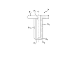
図4A、図4Bは、それぞれ第2シャフト部材3bの平面図、及び正面半断面図を示す。第2シャフト部材3bは、図4Bに示すように、押圧軸3b4と、押圧軸3b4の後方(図4Bにおける上方)に設けられ利用者がプランジャ3を押し込むための押圧フランジ3b1から構成されている。押圧軸3b4は、図4Bに示すように有底筒状の形状を有しており、前端面3f3は軸線Oに直交する水平面で構成されている。なお、押圧軸3b4は有底筒状形状の他、中空筒状、有頂筒状、中実筒状等の他の形状を有していてもよい。また、押圧フランジ3b1は設けなくてもよい。押圧軸3b4の外側面には、図4Aに示すように円周上の対向する位置に拡径部3b3が設けられている。そして、拡径部3b3の前端(図4Bにおける下端)には、第1シャフト部材3aの受圧面3a7に当接して押圧力を伝達するための押圧端面3f1が設けられている。また、拡径部3b3の外側面には係合突部3b2が設けられている。係合突部3b2は、第2シャフト部材3bを第1シャフト部材3aの筒部挿入孔3a10に挿入したときに、筒部3a9に設けられた開口3a8に係合して、筒部3a9からの抜け出しを防止する。なお、係合突部3b2を係止させる手段は上記態様に限定されず、例えば筒部3a9の内周面に突部を設け、係合突部3b2が当該突部を乗り越えるように構成してもよい。図5等に示すように、第1シャフト部材3aの筒部挿入孔3a10には、拡径溝3a13が設けられている。そして、筒部挿入孔3a10に第2シャフト部材3bを挿入する際には、拡径部3b3が第1シャフト部材3aの拡径溝3a13に嵌入する。これにより、第2シャフト部材3bを第1シャフト部材3aに挿入する際に、周方向の位置合わせを併せて行うことができるので、組み立て性が向上する。なお、拡径部3b3、及び拡径溝3a13は必須の構成ではなく、筒部挿入孔3a10、及び押圧軸3b4の側面が円筒側面形状を有していてもよい。押圧端面3f1の内周側には、全周にわたってテーパ面3f2が設けられている。
次に、内容物Cとして点鼻薬を用いる場合を例に、本実施形態の使用方法を説明する。
利用者は先ず、図2に示すように、前方のリブ3a12がフランジ部2dの内周端に当接している状態で先端部2cを一方の鼻の穴に挿入した後、第2シャフト部材3bの押圧フランジ3b1を前方に向かって押し込む。このとき、第2シャフト部材3bの押圧軸3b4は第1シャフト部材3aの筒部3a9に挿入されているため、第2シャフト部材3bの押圧時に第1シャフト部材3aに対してぐらついたり傾いたりすることがなく、安定した押圧動作が可能となる。そして、図6Bに示すように、第2シャフト部材3bに設けられた押圧端面3f1が、第1シャフト部材3aの係止突起3a3の後端面に設けられた受圧面3a7に当接する。このとき、押圧端面3f1は受圧面3a7のうち、内周側の受圧水平面3a70に当接する。これによって、第1シャフト部材3aも第2シャフト部材3bと共に前方へと押し込まれる。このとき、第1シャフト部材3aの摺動突起3a2は、先端に向かって先細りするテーパ部3foを有しているため、第1シャフト部材3aはシリンジ後端開口部A2からシリンジ2内に進入することができる。
第2シャフト部材3bの押圧端面3f1が、弾性片3a1の受圧水平面3a70に接触して押圧するため、弾性片3a1の自由端の動きは、シリンジ2との間で拘束される。その結果、弾性片3a1には、図6Aに示すように、摺動突起3a2を起点にした撓み変形が生じる。ここで、弾性片3a1の自由端は、受圧面3a7が押圧端面3f1及びテーパ面3f2により径方向内方への変位を規制されているため、係止突起3a3が初期位置のまま保持される。なお、前記自由端を外周側へ変位させるように第2シャフト部材の外径等を適宜変更しても良い。前記撓み変形を生じつつ、摺動突起3a2は、シリンジ2の内周面2fを摺動することによってプランジャ3の押し込みを許容することができる。これにより、図6Bに示すように、弾性片3a1に設けた係止突起3a3がフランジ部2dの後端に接触するまで、先端貫通孔A1から内容物C(点鼻薬)を鼻の穴に一定量噴出することができる。
弾性片3a1に設けた係止突起3a3がフランジ部2dの後端に接触すると、プランジャ3を押し込むことができなくなる。従って、空間Rに一定量の内容物C(点鼻薬)を残した状態で1回目の噴出は終了する。なお、1回目に噴出される内容物Cの容量は、使用目的に応じて適宜選択することができる。例えば、1回目に噴出される内容物Cの容量は、図1における空間Rの容量の半分とすることができる。
続いて、第2シャフト部材3bの押圧を緩和すると、図7Aに示すように、上記の撓み変形の復元力によって、弾性片3a1の自由端側が摺動突起3a2を起点に復元する。このとき、第2シャフト部材3bは弾性片3a1の復元力によって後方へと押し戻され、第2シャフト部材3bに設けられた係合突部3b2は、図7Aに示すように第1シャフト部材3aの開口3a8の後端まで戻る。また、弾性片3a1の固定端側は、後方に向かうに従い内周側に変位するように変形したままであるから、弾性片3a1の自由端側は、図7Aに示すように、固定端側と整列するように内周方向へと復元する。このため、係止突起3a3も弾性片3a1の自由端側に追従するように内周方向に変位するので、当該係止突起3a3の係止状態が図7Aに示すように解除される。なお、係合突部3b2は、第2シャフト部材3bの抜け止め防止の役割を有しており、係合突部3b2が開口3a8の後端に当接した場合には、第2シャフト部材3bがそれ以上後方に移動することがない。
特に、本実施形態では、図7Bに示すように、押圧端面3f1の内周側にテーパ面3f2が設けられているため、第2シャフト部材3bの押圧を緩和した際に、上記の復元力によって第2シャフト部材3bが後方へと押し戻されるため、押圧端面3f1に当接していた係止突起3a3がこのテーパ面3f2に沿って内周方向に移動することができる。なお、本実施形態では、押圧を緩和したときに弾性片3a1の復元力によって第2シャフト部材3bが後方へ押し戻されるように構成したが、この態様に限定されず、第2シャフト部材3bを利用者が引っ張ることによって後方に引き戻されるように構成するなどしてもよい。また、摺動突起3a2と係止突起3a3とを薄肉部3a6によって連結することにより、第2シャフト部材3bの押圧を緩和したときに係止突起3a3がより大きく内周側に変位することができる。更に、図7Bの拡大図に示すように、弾性片3a1の自由端における受圧面3a7に受圧テーパ面3a71が設けられ、外周方向がやや前方に傾斜するように構成されている。これによって、図7Bのように、弾性片3a1の係止突起3a3が摺動突起3a2を起点にした撓み変形によって内周方向に変位した場合にも、弾性片3a1の自由端の径方向変位を第2シャフト部材3bが阻害しない。従って、係止突起3a3の内周方向への変位が第2シャフト部材3bによって妨げられることがない。
このように、本実施形態では、第2シャフト部材3bの押圧を緩和した際に係止突起3a3の内周方向への変位が大きく取れるように構成されている。これによって、1回目の内容物Cの噴出を停止させるための係止突起3a3とフランジ部2dの後端との重なり代rを大きくとることができる(図6B参照)。従って、1回目の内容物Cの噴出を確実に停止させることができる。
第2シャフト部材3bの押圧を緩和した後、図7Aに示すように後方のリブ3a12がフランジ部2dの内周端に当接している状態で再び第2シャフト部材3bを押圧すれば、2回目の噴出が可能になる。すなわち、本実施形態では、第2シャフト部材3bの押圧を緩和した後に再度押圧すれば、図7Bに示すように、摺動突起3a2を起点にした弾性片3a1の復元により、第2シャフト部材3bの前端面3f3が、受圧テーパ面3a71に接触する。このため、再び第2シャフト部材3bの押圧によって第1シャフト部材3aを押し込むことができる。
特に、本実施形態では、受圧テーパ面3a71が、初期状態で外周側に向けて前方に傾くように構成されている。このため、弾性片3a1の自由端側が摺動突起3a2を起点に復元したときに、第2シャフト部材3bの前端面3f3と受圧テーパ面3a71とが平行に近い状態で接触できる。従って、第1シャフト部材3aの押し込みを円滑に行うことができる。
図7Aに示すように、利用者は、第2シャフト部材3bの押圧を緩和して第2シャフト部材3bが押し戻された後、他方の鼻の穴に先端部2cを挿入する。そして、利用者が第2シャフト部材3bを再度押し込めば、先端貫通孔A1から空間R内に残った内容物C(点鼻薬)を鼻の穴に噴出することができる。
なお、1回目の内容物Cの噴出の際にリブ3a12がフランジ部2dの内周端を通過するのに必要な押圧力と、2回目の内容物Cの噴出の際にリブ3a12がフランジ部2dの内周端を通過するのに必要な押圧力とが概ね等しくなるように、前方及び後方のリブ3a12の高さが調整されていることが望ましい。
上述のように、本実施形態によれば、内容物Cを小分けして噴出することができる。加えて、本実施形態では、第2シャフト部材3bの押圧を緩和した後に再度押圧すると2回目の噴出が可能になるため、2回目の噴出を行うときに持ち替える必要がない。このため、利用者は、内容物Cの小分けを片手操作で行うことができる。特に、本実施形態では、プランジャ3が、先端にピストン4を有する第1シャフト部材3aと、第1シャフト部材3aの筒部3a9に嵌合する有底筒状形状の押圧軸3b4を有する第2シャフト部材3bから構成され、第2シャフト部材3bの外周面に設けた係合突部3b2が筒部3a9に設けた開口3a8に係合するように構成した。これによって、第2シャフト部材3bは、押圧及び押圧の緩和により筒部3a9に設けた筒部挿入孔3a10内を軸線O方向に滑らかに移動することができる。しかも、第2シャフト部材3bは、係合突部3b2の係合によって第1シャフト部材3aから抜け出してしまうことがない。すなわち、押圧時に第2シャフト部材3bが第1シャフト部材3aに対してぐらついたり傾いたり脱落したりすることがない。従って、押圧時におけるシリンジ型噴出器1の操作性が向上する。
また、本実施形態によれば、第2シャフト部材3bの押圧が緩和されたときの前端面3f3の位置は、係合突部3b2が筒部3a9の開口3a8に当接することにより決定される。そのため、第2シャフト部材3bの押圧が緩和されたときに、第2シャフト部材3bの前端面3f3が押し戻しによって受圧面3a7から過度に離れることがない。従って、2回目の内容物Cの噴出を円滑に行うことができる。
また、本実施形態によれば、摺動突起3a2と係止突起3a3とは、半径方向の厚みが薄く形成された薄肉部3a6により連結されるように構成した。更に、本実施形態では、第2シャフト部材3bの押圧軸3b4が有底筒状形状を有し、その前端面3f3が水平面で構成されているため、内周方向に変位した弾性片3a1の自由端が第2シャフト部材3bに半径方向から接触することがない。これによって、押圧を緩和したときの復元力による係止突起3a3の内周方向への変位を大きくとることができる。そのため、1回目の内容物Cの噴出を停止させるための係止突起3a3とフランジ部2dの後端との重なり代rを大きくとることができる(図6B参照)。従って、1回目の内容物Cの噴出を確実に停止させることができる。
また、本実施形態によれば、弾性片3a1は、根元から摺動突起3a2にかけてテーパ部3f0を設けて半径方向の厚みが漸増するように形成した。これによって、第2シャフト部材3bの押圧開始後、摺動突起3a2がシリンジ2の内周面2fを摺動するようになるまで、第1シャフト部材3aの押し込みを円滑に行うことができる。
また、本実施形態によれば、押圧端面3f1の内周側にテーパ面3f2を設けるようにした。これによって、押圧端面3f1による押圧を緩和した際に、係止突起3a3がこのテーパ面3f2に沿って容易に内周方向に移動することができる。
また、本実施形態によれば、第1シャフト部材3aの外周面に、押圧の開始位置においてフランジ部2dの内周端に係合するリブ3a12を設けるように構成した。これによって、利用者は、内容物Cの噴出が開始されるプランジャ3位置を押圧抵抗により把握することができる。従って、利用者が意図しない場所で誤ってプランジャ3を押し込んで内容物Cを噴出させてしまうことがない。
また、本実施形態によれば、第1シャフト部材3aの筒部挿入孔3a10に筒状の第2シャフト部材3bを挿入する構成であるため、プランジャ3の組み立てが容易となる。また、前記筒部挿入孔3a10に拡径溝3a13を設けて、筒部挿入孔3a10に第2シャフト部材3bを挿入する際に、拡径部3b3が第1シャフト部材3aの拡径溝3a13に嵌入するように構成した。これにより、第2シャフト部材3bを第1シャフト部材3aに挿入する際に、周方向の位置合わせを併せて行うことができるので、組み立て性がさらに向上する。
上述したところは、本発明の様々な実施形態であるが、本発明に従えば、様々な変更が可能となる。例えば、弾性片3a1は、少なくとも1箇所に設けることができるが、プランジャ3を確実に停止させて正確な小分けを実現する場合には、本形態のように複数設けることが好ましい。特に、本実施形態のように、対向位置に一対となるように配置すれば、軸線O周りのバランスが安定するため、良好な操作が実現できる。上述の実施形態では、内容物Cを通常の液体として噴出させるものとして説明したが、本発明に従えば、泡として噴出させ、又は霧状態で噴出させるなど、内容物Cを様々な形態で噴出させることができる。
本発明は、シリンジ2と、当該シリンジ2内に押し込み可能なプランジャ3とを備えるシリンジ型噴出器1であれば、様々な形態のものに採用することができる。内容物Cも、点鼻薬に限定されることなく、様々なものを採用することができる。
1 シリンジ型噴出器
2 シリンジ
2a 胴部
2b 肩部
2c 先端部
2d フランジ部
2d0 シリンジ後端部
2f 内周面
3 プランジャ
3a 第1シャフト部材
3a1 弾性片
3a2 摺動突起
3a3 係止突起
3a4 基部
3a6 薄肉部
3a7 受圧面
3a70 受圧水平面
3a71 受圧テーパ面
3a8 開口
3a9 筒部
3a10 筒部挿入孔
3a11 ピストン固定雄ねじ
3a12 リブ
3a13 拡径溝
3b 第2シャフト部材
3b1 押圧フランジ
3b2 係合突部
3b3 拡径部
3b4 押圧軸
3f0 テーパ部
3f1 押圧端面(端面)
3f2 テーパ面
3f3 前端面
4 ピストン
A1 先端貫通孔
A2 後端開口部
C 内容物
O 軸線
R 空間
r 重なり代
2 シリンジ
2a 胴部
2b 肩部
2c 先端部
2d フランジ部
2d0 シリンジ後端部
2f 内周面
3 プランジャ
3a 第1シャフト部材
3a1 弾性片
3a2 摺動突起
3a3 係止突起
3a4 基部
3a6 薄肉部
3a7 受圧面
3a70 受圧水平面
3a71 受圧テーパ面
3a8 開口
3a9 筒部
3a10 筒部挿入孔
3a11 ピストン固定雄ねじ
3a12 リブ
3a13 拡径溝
3b 第2シャフト部材
3b1 押圧フランジ
3b2 係合突部
3b3 拡径部
3b4 押圧軸
3f0 テーパ部
3f1 押圧端面(端面)
3f2 テーパ面
3f3 前端面
4 ピストン
A1 先端貫通孔
A2 後端開口部
C 内容物
O 軸線
R 空間
r 重なり代
Claims (7)
- シリンジと、該シリンジ内に押し込み可能なプランジャとを備えるシリンジ型噴出器であって、
前記プランジャは、先端にピストンを有する第1シャフト部材と、該第1シャフト部材の筒部に嵌合する第2シャフト部材とを有し、
前記第1シャフト部材は、後方に向かって伸びる少なくとも1つの弾性片を有し、該弾性片には、前記シリンジの後端開口部から進入して該シリンジの内周面を摺動可能な摺動突起と、前記シリンジの後端に係止される係止突起とが設けられており、
前記第2シャフト部材は、前記筒部に嵌合する押圧軸を有し、前記押圧軸の先端には前記弾性片の自由端を押圧する端面が設けられると共に、前記押圧軸の外周面には前記筒部の係止部に係合して該筒部からの抜け出しを防止する係合突部が設けられ、
前記端面からの押圧によって、前記弾性片の自由端を前記シリンジとの間で拘束することで前記弾性片に前記摺動突起を起点にした撓み変形を生じさせて前記係止突起を前記シリンジの後端に係止させ、
前記押圧の緩和によって、前記撓み変形の前記摺動突起を起点にした復元力によって前記係止突起の係止が解除されることを特徴とするシリンジ型噴出器。 - 前記筒部には半径方向に貫通する開口が設けられ、該開口内に前記弾性片を配置すると共に、該開口の後端縁を前記係止部とする、請求項1に記載のシリンジ型噴出器。
- 前記押圧が緩和されたときの前記端面の位置は、前記係合突部が前記筒部の前記係止部に当接することにより決定される、請求項1又は2に記載のシリンジ型噴出器。
- 前記摺動突起と前記係止突起は、半径方向の厚みが薄く形成された薄肉部により連結されている、請求項1乃至3のいずれか一項に記載のシリンジ型噴出器。
- 前記弾性片は、根元から前記摺動突起にかけて、半径方向の厚みが漸増するように形成されている、請求項1乃至4のいずれか一項に記載のシリンジ型噴出器。
- 前記端面にテーパ面が形成されている、請求項1乃至5のいずれか一項に記載のシリンジ型噴出器。
- 前記第1シャフト部材の外周面に、前記押圧の開始位置において前記シリンジの後端に係合するリブを設けてなる、請求項1乃至6のいずれか一項に記載のシリンジ型噴出器。
Priority Applications (3)
| Application Number | Priority Date | Filing Date | Title |
|---|---|---|---|
| CN201680061885.3A CN108136133B (zh) | 2015-10-29 | 2016-08-18 | 注射器型喷出器 |
| EP16859233.5A EP3369449B1 (en) | 2015-10-29 | 2016-08-18 | Syringe-type ejector |
| US15/767,865 US10850040B2 (en) | 2015-10-29 | 2016-08-18 | Syringe-type ejector |
Applications Claiming Priority (2)
| Application Number | Priority Date | Filing Date | Title |
|---|---|---|---|
| JP2015-213403 | 2015-10-29 | ||
| JP2015213403A JP6579918B2 (ja) | 2015-10-29 | 2015-10-29 | シリンジ型噴出器 |
Publications (1)
| Publication Number | Publication Date |
|---|---|
| WO2017072992A1 true WO2017072992A1 (ja) | 2017-05-04 |
Family
ID=58630019
Family Applications (1)
| Application Number | Title | Priority Date | Filing Date |
|---|---|---|---|
| PCT/JP2016/003784 Ceased WO2017072992A1 (ja) | 2015-10-29 | 2016-08-18 | シリンジ型噴出器 |
Country Status (5)
| Country | Link |
|---|---|
| US (1) | US10850040B2 (ja) |
| EP (1) | EP3369449B1 (ja) |
| JP (1) | JP6579918B2 (ja) |
| CN (1) | CN108136133B (ja) |
| WO (1) | WO2017072992A1 (ja) |
Cited By (2)
| Publication number | Priority date | Publication date | Assignee | Title |
|---|---|---|---|---|
| CN110624158A (zh) * | 2018-06-21 | 2019-12-31 | 株式会社松风 | 注入器 |
| WO2025121395A1 (ja) * | 2023-12-07 | 2025-06-12 | 大成化工株式会社 | シリンジ |
Families Citing this family (2)
| Publication number | Priority date | Publication date | Assignee | Title |
|---|---|---|---|---|
| IL257778B (en) * | 2018-02-27 | 2022-07-01 | Equashield Medical Ltd | Device for securing device connections |
| KR20220160659A (ko) | 2020-03-31 | 2022-12-06 | 가부시끼가이샤 다이쿄 세이코 | 의료용 시린지 플런저 및 의료용 핑거 그립 |
Citations (3)
| Publication number | Priority date | Publication date | Assignee | Title |
|---|---|---|---|---|
| JP2012249716A (ja) * | 2011-05-31 | 2012-12-20 | Yoshino Kogyosho Co Ltd | 使い切り注射器 |
| JP2013208603A (ja) * | 2012-03-30 | 2013-10-10 | Yoshino Kogyosho Co Ltd | 定量シリンジ型噴出器 |
| JP2015104574A (ja) * | 2013-11-29 | 2015-06-08 | 株式会社吉野工業所 | 定量シリンジ型噴出器 |
Family Cites Families (5)
| Publication number | Priority date | Publication date | Assignee | Title |
|---|---|---|---|---|
| JPH07213612A (ja) | 1994-02-04 | 1995-08-15 | Kato Hatsujo Kaisha Ltd | シリンジ |
| US9597455B2 (en) * | 2011-09-30 | 2017-03-21 | Becton Dickinson France S.A.S. | Syringe having a spring action plunger rod |
| WO2013145789A1 (ja) | 2012-03-30 | 2013-10-03 | 株式会社吉野工業所 | 定量シリンジ型噴出器 |
| JP5819781B2 (ja) | 2012-05-31 | 2015-11-24 | 株式会社吉野工業所 | 定量シリンジ型噴出器 |
| US9968743B2 (en) * | 2012-11-30 | 2018-05-15 | Yoshino Kogyosho Co., Ltd. | Quantitative syringe-type ejector |
-
2015
- 2015-10-29 JP JP2015213403A patent/JP6579918B2/ja active Active
-
2016
- 2016-08-18 EP EP16859233.5A patent/EP3369449B1/en active Active
- 2016-08-18 WO PCT/JP2016/003784 patent/WO2017072992A1/ja not_active Ceased
- 2016-08-18 CN CN201680061885.3A patent/CN108136133B/zh active Active
- 2016-08-18 US US15/767,865 patent/US10850040B2/en active Active
Patent Citations (3)
| Publication number | Priority date | Publication date | Assignee | Title |
|---|---|---|---|---|
| JP2012249716A (ja) * | 2011-05-31 | 2012-12-20 | Yoshino Kogyosho Co Ltd | 使い切り注射器 |
| JP2013208603A (ja) * | 2012-03-30 | 2013-10-10 | Yoshino Kogyosho Co Ltd | 定量シリンジ型噴出器 |
| JP2015104574A (ja) * | 2013-11-29 | 2015-06-08 | 株式会社吉野工業所 | 定量シリンジ型噴出器 |
Cited By (5)
| Publication number | Priority date | Publication date | Assignee | Title |
|---|---|---|---|---|
| CN110624158A (zh) * | 2018-06-21 | 2019-12-31 | 株式会社松风 | 注入器 |
| EP3586894A1 (en) * | 2018-06-21 | 2020-01-01 | Kabushiki Kaisha Shofu | Injector |
| US11319139B2 (en) | 2018-06-21 | 2022-05-03 | Kabushiki Kaisha Shofu | Injector |
| CN110624158B (zh) * | 2018-06-21 | 2023-10-27 | 株式会社松风 | 注入器 |
| WO2025121395A1 (ja) * | 2023-12-07 | 2025-06-12 | 大成化工株式会社 | シリンジ |
Also Published As
| Publication number | Publication date |
|---|---|
| JP2017080189A (ja) | 2017-05-18 |
| EP3369449B1 (en) | 2020-10-28 |
| CN108136133A (zh) | 2018-06-08 |
| JP6579918B2 (ja) | 2019-09-25 |
| CN108136133B (zh) | 2021-01-08 |
| US20180296766A1 (en) | 2018-10-18 |
| EP3369449A4 (en) | 2019-06-05 |
| US10850040B2 (en) | 2020-12-01 |
| EP3369449A1 (en) | 2018-09-05 |
Similar Documents
| Publication | Publication Date | Title |
|---|---|---|
| JP5786852B2 (ja) | 鼻腔投与容器 | |
| JP6579918B2 (ja) | シリンジ型噴出器 | |
| JPH05161712A (ja) | 注射器 | |
| JP5855531B2 (ja) | 定量シリンジ型噴出器 | |
| EP2926849B1 (en) | Metered syringe-type ejector | |
| JP5882106B2 (ja) | 定量シリンジ型噴出器 | |
| JP5847662B2 (ja) | 定量シリンジ型噴出器 | |
| CN101242962A (zh) | 用于接近书写工具墨水腔的快速松开机构 | |
| JP5819781B2 (ja) | 定量シリンジ型噴出器 | |
| JP6730180B2 (ja) | シリンジ型噴出器 | |
| JP5864337B2 (ja) | 定量シリンジ型噴出器 | |
| JP6305793B2 (ja) | 定量シリンジ型噴出器 | |
| KR102786372B1 (ko) | 플런저 키트, 시린지 키트 및 프리필드 시린지 | |
| US20080154195A1 (en) | Safety syringe device | |
| JP6488219B2 (ja) | 吐出器および吐出器の製造方法 | |
| JP6284755B2 (ja) | 定量シリンジ型噴出器 | |
| JP5677833B2 (ja) | シリンジ容器 | |
| JP6590621B2 (ja) | 吐出器および吐出器の製造方法 | |
| JP5868822B2 (ja) | 定量シリンジ型噴出器 | |
| US7141039B2 (en) | Structure of safety hypodermic syringe | |
| JP5868782B2 (ja) | 定量シリンジ型噴出器 | |
| JP6165506B2 (ja) | シリンジ型噴出容器 | |
| JP6284790B2 (ja) | 定量シリンジ型噴出器 | |
| JP2024172542A (ja) | プランジャ及びシリンジ型噴出器 | |
| EP1862191A1 (en) | Safety syringe device |
Legal Events
| Date | Code | Title | Description |
|---|---|---|---|
| 121 | Ep: the epo has been informed by wipo that ep was designated in this application |
Ref document number: 16859233 Country of ref document: EP Kind code of ref document: A1 |
|
| WWE | Wipo information: entry into national phase |
Ref document number: 15767865 Country of ref document: US |
|
| NENP | Non-entry into the national phase |
Ref country code: DE |
|
| WWE | Wipo information: entry into national phase |
Ref document number: 2016859233 Country of ref document: EP |