WO2017069197A1 - 舶用減速装置 - Google Patents
舶用減速装置 Download PDFInfo
- Publication number
- WO2017069197A1 WO2017069197A1 PCT/JP2016/081110 JP2016081110W WO2017069197A1 WO 2017069197 A1 WO2017069197 A1 WO 2017069197A1 JP 2016081110 W JP2016081110 W JP 2016081110W WO 2017069197 A1 WO2017069197 A1 WO 2017069197A1
- Authority
- WO
- WIPO (PCT)
- Prior art keywords
- rotating machine
- shaft
- electric rotating
- coolant
- lubricating oil
- Prior art date
- Legal status (The legal status is an assumption and is not a legal conclusion. Google has not performed a legal analysis and makes no representation as to the accuracy of the status listed.)
- Ceased
Links
Images

Classifications
-
- B—PERFORMING OPERATIONS; TRANSPORTING
- B63—SHIPS OR OTHER WATERBORNE VESSELS; RELATED EQUIPMENT
- B63H—MARINE PROPULSION OR STEERING
- B63H23/00—Transmitting power from propulsion power plant to propulsive elements
- B63H23/02—Transmitting power from propulsion power plant to propulsive elements with mechanical gearing
- B63H23/10—Transmitting power from propulsion power plant to propulsive elements with mechanical gearing for transmitting drive from more than one propulsion power unit
- B63H23/12—Transmitting power from propulsion power plant to propulsive elements with mechanical gearing for transmitting drive from more than one propulsion power unit allowing combined use of the propulsion power units
-
- B—PERFORMING OPERATIONS; TRANSPORTING
- B63—SHIPS OR OTHER WATERBORNE VESSELS; RELATED EQUIPMENT
- B63H—MARINE PROPULSION OR STEERING
- B63H21/00—Use of propulsion power plant or units on vessels
- B63H21/12—Use of propulsion power plant or units on vessels the vessels being motor-driven
- B63H21/17—Use of propulsion power plant or units on vessels the vessels being motor-driven by electric motor
-
- B—PERFORMING OPERATIONS; TRANSPORTING
- B63—SHIPS OR OTHER WATERBORNE VESSELS; RELATED EQUIPMENT
- B63H—MARINE PROPULSION OR STEERING
- B63H21/00—Use of propulsion power plant or units on vessels
- B63H21/20—Use of propulsion power plant or units on vessels the vessels being powered by combinations of different types of propulsion units
-
- B—PERFORMING OPERATIONS; TRANSPORTING
- B63—SHIPS OR OTHER WATERBORNE VESSELS; RELATED EQUIPMENT
- B63H—MARINE PROPULSION OR STEERING
- B63H21/00—Use of propulsion power plant or units on vessels
- B63H21/38—Apparatus or methods specially adapted for use on marine vessels, for handling power plant or unit liquids, e.g. lubricants, coolants, fuels or the like
-
- B—PERFORMING OPERATIONS; TRANSPORTING
- B63—SHIPS OR OTHER WATERBORNE VESSELS; RELATED EQUIPMENT
- B63J—AUXILIARIES ON VESSELS
- B63J3/00—Driving of auxiliaries
- B63J3/02—Driving of auxiliaries from propulsion power plant
-
- F—MECHANICAL ENGINEERING; LIGHTING; HEATING; WEAPONS; BLASTING
- F16—ENGINEERING ELEMENTS AND UNITS; GENERAL MEASURES FOR PRODUCING AND MAINTAINING EFFECTIVE FUNCTIONING OF MACHINES OR INSTALLATIONS; THERMAL INSULATION IN GENERAL
- F16H—GEARING
- F16H1/00—Toothed gearings for conveying rotary motion
- F16H1/02—Toothed gearings for conveying rotary motion without gears having orbital motion
- F16H1/04—Toothed gearings for conveying rotary motion without gears having orbital motion involving only two intermeshing members
- F16H1/06—Toothed gearings for conveying rotary motion without gears having orbital motion involving only two intermeshing members with parallel axes
-
- F—MECHANICAL ENGINEERING; LIGHTING; HEATING; WEAPONS; BLASTING
- F16—ENGINEERING ELEMENTS AND UNITS; GENERAL MEASURES FOR PRODUCING AND MAINTAINING EFFECTIVE FUNCTIONING OF MACHINES OR INSTALLATIONS; THERMAL INSULATION IN GENERAL
- F16H—GEARING
- F16H57/00—General details of gearing
- F16H57/04—Features relating to lubrication or cooling or heating
- F16H57/0412—Cooling or heating; Control of temperature
-
- F—MECHANICAL ENGINEERING; LIGHTING; HEATING; WEAPONS; BLASTING
- F16—ENGINEERING ELEMENTS AND UNITS; GENERAL MEASURES FOR PRODUCING AND MAINTAINING EFFECTIVE FUNCTIONING OF MACHINES OR INSTALLATIONS; THERMAL INSULATION IN GENERAL
- F16H—GEARING
- F16H57/00—General details of gearing
- F16H57/04—Features relating to lubrication or cooling or heating
- F16H57/0434—Features relating to lubrication or cooling or heating relating to lubrication supply, e.g. pumps; Pressure control
- F16H57/0436—Pumps
-
- B—PERFORMING OPERATIONS; TRANSPORTING
- B63—SHIPS OR OTHER WATERBORNE VESSELS; RELATED EQUIPMENT
- B63H—MARINE PROPULSION OR STEERING
- B63H21/00—Use of propulsion power plant or units on vessels
- B63H21/20—Use of propulsion power plant or units on vessels the vessels being powered by combinations of different types of propulsion units
- B63H2021/202—Use of propulsion power plant or units on vessels the vessels being powered by combinations of different types of propulsion units of hybrid electric type
- B63H2021/205—Use of propulsion power plant or units on vessels the vessels being powered by combinations of different types of propulsion units of hybrid electric type the second power unit being of the internal combustion engine type, or the like, e.g. a Diesel engine
-
- B—PERFORMING OPERATIONS; TRANSPORTING
- B63—SHIPS OR OTHER WATERBORNE VESSELS; RELATED EQUIPMENT
- B63H—MARINE PROPULSION OR STEERING
- B63H21/00—Use of propulsion power plant or units on vessels
- B63H21/20—Use of propulsion power plant or units on vessels the vessels being powered by combinations of different types of propulsion units
- B63H2021/202—Use of propulsion power plant or units on vessels the vessels being powered by combinations of different types of propulsion units of hybrid electric type
- B63H2021/207—Use of propulsion power plant or units on vessels the vessels being powered by combinations of different types of propulsion units of hybrid electric type the second power unit being a gas turbine
-
- H—ELECTRICITY
- H02—GENERATION; CONVERSION OR DISTRIBUTION OF ELECTRIC POWER
- H02K—DYNAMO-ELECTRIC MACHINES
- H02K7/00—Arrangements for handling mechanical energy structurally associated with dynamo-electric machines, e.g. structural association with mechanical driving motors or auxiliary dynamo-electric machines
- H02K7/10—Structural association with clutches, brakes, gears, pulleys or mechanical starters
- H02K7/116—Structural association with clutches, brakes, gears, pulleys or mechanical starters with gears
-
- Y—GENERAL TAGGING OF NEW TECHNOLOGICAL DEVELOPMENTS; GENERAL TAGGING OF CROSS-SECTIONAL TECHNOLOGIES SPANNING OVER SEVERAL SECTIONS OF THE IPC; TECHNICAL SUBJECTS COVERED BY FORMER USPC CROSS-REFERENCE ART COLLECTIONS [XRACs] AND DIGESTS
- Y02—TECHNOLOGIES OR APPLICATIONS FOR MITIGATION OR ADAPTATION AGAINST CLIMATE CHANGE
- Y02T—CLIMATE CHANGE MITIGATION TECHNOLOGIES RELATED TO TRANSPORTATION
- Y02T70/00—Maritime or waterways transport
- Y02T70/50—Measures to reduce greenhouse gas emissions related to the propulsion system
- Y02T70/5218—Less carbon-intensive fuels, e.g. natural gas, biofuels
- Y02T70/5236—Renewable or hybrid-electric solutions
Definitions
- the present invention relates to a marine speed reducing device.
- electric power is generated by a reduction gear disposed between a propulsion shaft and the engine in order to generate electric power with the surplus output of the engine that drives the screw propeller via the propulsion shaft or to assist the output of the engine with electric power.
- a rotating machine may be connected (for example, refer to patent documents 1).
- an object of the present invention is to provide a marine speed reducing device that can reduce the installation space of an electric rotating machine.
- a marine speed reducing device of the present invention is provided on an input shaft connected to an output shaft of an engine, an output shaft connected to a propulsion shaft that rotates a screw propeller, and the input shaft.
- the input gear and the output gear provided on the output shaft are accommodated, and a gear box that supports a first bearing that rotatably supports the output shaft, a central shaft that rotates together with the output shaft, and a fixed to the central shaft
- An electric rotating machine including a rotor and a stator surrounding the rotor, and a second bearing that rotatably supports the central shaft of the electric rotating machine and the stator are supported by the gear box, It is characterized by that.
- the electric rotating machine is integrated into the gear box, the installation space for the electric rotating machine can be reduced. Moreover, since the gear box also serves as the casing of the electric rotating machine, the weight of the entire system including the speed reduction mechanism and the electric rotating machine can be reduced.
- the marine speed reducing device further includes a lubricating oil pump attached to the gear box and driven by the input shaft, and the lubricating oil pump supplies the lubricating oil so that the lubricating oil flows down in the gear box. While circulating, supplying lubricating oil to the second bearing, the lubricating oil supplied to the second bearing may be discharged from the second bearing into the gear box. According to this configuration, the lubricating oil can be supplied to the bearing for the central shaft of the electric rotating machine by using the lubricating oil pump that supplies the lubricating oil to the gear in the gear box. Moreover, the lubricating oil supplied to the bearing for the central shaft of the electric rotating machine is discharged from the bearing into the gear box. Therefore, the bottom of the gear box can be used as a lubricant receiver common to the gear and the electric rotating machine.
- the marine speed reduction device further includes a coolant pump attached to the gear box and driven by the input shaft, and the coolant pump flows in contact with the stator of the electric rotating machine.
- a coolant may be supplied to the electric rotating machine.
- the electric rotating machine can be made smaller than when the electric rotating machine is cooled by applying wind.
- the coolant pump can be driven using the output of the engine or electric rotating machine distributed in the gear box.
- the coolant pump supplies a coolant to the electric rotating machine through a first coolant supply line and supplies a coolant to a heat exchanger through a second coolant supply line.
- the lubricating oil may be cooled by heat exchange between the lubricating oil sucked into the oil pump or the lubricating oil discharged from the lubricating oil pump and the coolant. According to this configuration, it is possible to cool the electric rotating machine and the lubricating oil by using one coolant pump.
- the installation space for the electric rotating machine can be reduced.
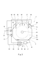
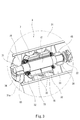
- FIG. 1 It is a top view showing a schematic structure of a marine speed reducing device concerning one embodiment of the present invention. It is a front view of the marine speed reducing device shown in FIG. It is a perspective view which shows an electric rotary machine in a cross section.
- the marine speed reduction device 2 is disposed in the engine room of the marine vessel together with the engine 11.
- the marine speed reducing device 2 includes an input shaft 40 coupled to the output shaft 12 of the engine 11 and an output shaft 43 coupled to the propulsion shaft 13 that rotates the screw propeller 14.
- the propulsion shaft 13 side in the axial direction of the output shaft 43 is referred to as the rear, and the opposite side is referred to as the front.
- the engine 11 is disposed behind the marine speed reducing device 2. However, the engine 11 may be disposed in front of the marine speed reducing device 2.
- the engine 11 may be a gas turbine engine or a 2-stroke or 4-stroke reciprocating engine.
- the input shaft 51 is provided with an input gear 51
- the output shaft 43 is provided with an output gear 55.
- the input gear 51 and the output gear 55 may mesh directly, or may mesh via another gear (one or more).
- the input gear 51 and the output gear 55 are accommodated in the gear box 3.
- the input shaft 40 parallel to the output shaft 43 protrudes rearward from the gear box 3 and is connected to the output shaft 12 of the engine 11 by a flange connection.
- the output shaft 43 protrudes rearward from the gear box 3 and is connected to the propulsion shaft 13 by a flange connection.
- the input shaft 40 is divided into a rear portion 42 provided with the input gear 51 and a front portion 41 penetrating the gear box 3.
- the front part 41 and the rear part 42 of the input shaft 40 are connected via the clutch 21.
- the input shaft 40 may be an integral object, and the input shaft 40 may be connected to the output shaft 12 of the engine 11 via the clutch 21 outside the gear box 3.
- the gear box 3 supports a bearing 61 that rotatably supports the front portion 41 of the input shaft 40 and a bearing 62 that rotatably supports the rear portion 42 of the input shaft 40.
- the gear box 3 also supports a bearing 63 (corresponding to the first bearing of the present invention) that rotatably supports the output shaft 43.
- the electric rotating machine 7 is integrally incorporated in the gear box 3, and the lubricating oil pump 15 and the coolant pump 16 are attached to the gear box 3.
- Lubricating oil pump 15 and coolant pump 16 are driven by input shaft 40. More specifically, a drive gear 52 is provided on the rear portion 42 of the input shaft 40, and driven gears 53 and 54 are provided on the rotation shafts of the lubricating oil pump 15 and the coolant pump 16, respectively.
- the drive gear 52 and the driven gears 53 and 54 may mesh directly, or may mesh via another gear (one or more).
- the drive gear 52 and the driven gears 53 and 54 are also accommodated in the gear box 3. The roles of the lubricating oil pump 15 and the coolant pump 16 will be described later.
- the electric rotating machine 7 functions as a generator and an electric motor.
- the clutch 21 is turned on (connected state).
- the electric rotating machine 7 assists the output of the engine 11 when the clutch 21 is turned on, and the electric rotating machine 7 when the clutch 21 is turned off (disconnected state). Only the screw propeller 14 is rotated.
- the electric rotating machine 7 may function only as a generator or may function only as an electric motor.
- the clutch 22 described later is turned on (connected state) when the electric rotary machine 7 functions as a generator and also functions as an electric motor.
- the electric rotating machine 7 includes a center shaft 71 that rotates together with the output shaft 43 and extends in the front-rear direction, a rotor 72 fixed to the center shaft 71, and a stator 73 that surrounds the rotor 72.
- a first relay shaft 44 and a second relay shaft 45 that are parallel to the center shaft 71 and the output shaft 43 are provided.
- the second relay shaft 45 is disposed in front of the central shaft 71, and the first relay shaft 44 is disposed on the side of the central shaft 71 and the second relay shaft 45 of the electric rotating machine 7.
- the first relay shaft 44 is provided with a first relay gear 56 that meshes directly with the output gear 55 or via another gear (one or more), and is further forward than the first relay gear 56.
- a second relay gear 57 is provided.
- a bearing 64 that rotatably supports the first relay shaft 44 is supported by the gear box 3.
- the second relay shaft 45 is provided with an input / output gear 58 that meshes with the second relay gear 57 directly or via another gear (one or more).
- the second relay shaft 45 is connected to the central shaft 71 of the electric rotating machine 7 via the clutch 22.
- the clutch 22 is turned off (non-contact state) when the electric rotating machine 7 fails in order to prevent the output shaft 43 from being unable to rotate due to a failure of the electric rotating machine 7.
- the clutch 22 may be turned off when it is desired to reduce the mechanical loss caused by the electric rotating machine 7 when the electric rotating machine 7 is stopped when the screw propeller 14 is rotated using only the engine 11. Good.
- the second relay shaft 45 may be disposed behind the electric rotating machine 7.
- the first relay shaft 44, the second relay shaft 45, and the clutch 22 are omitted, and the input / output gear 58 is directly connected to the output gear 55 or another gear (one gear) on the central shaft 71 of the electric rotating machine 7.
- they may be provided so as to mesh with each other.
- the bearing 65 (corresponding to the second bearing of the present invention) that rotatably supports the central shaft 71 of the electric rotating machine 7 is supported by the gear box 3.
- the gear box 3 also supports a stator 73 of the electric rotating machine 7.
- the gear box 3 includes a main structure 31 in which the output gear 55 is disposed, and a first cover 36 and a second cover 37 that form a closed space together with the main structure 31.
- An input gear 51 is disposed in a closed space formed by the first cover 36 and the main structure 31, and the electric rotating machine 7 and the input / output gear are formed in a space formed by the second cover 37 and the main structure 31. 58 is arranged.
- the main structure 31 has a rear wall 31a and a front wall 31b (see FIG. 1) parallel to each other, and an output shaft 43 passes through the rear wall 31a and the front wall 31b.
- the bearing 63 that rotatably supports the output shaft 43 is supported by the rear wall 31a and the front wall 31b via a bearing base (not shown) attached to the rear wall 31a and the front wall 31b.
- FIG. 3 is a perspective view showing the electric rotating machine 7 in cross-section with the second cover 37 removed.
- the main structure 31 is provided with a partition wall 33 at a position corresponding to the front end of the central shaft 71 of the electric rotating machine 7.
- a bearing base half 35 is formed integrally with the partition wall 33.
- the bearing cover half 35 is integrally formed in the second cover 37 (illustration of the bearing base half 35 of the second cover 37 is omitted).
- a bearing 65 that rotatably supports the front end of the central shaft 71 of the electric rotating machine 7 is supported by the partition wall 33 and the second cover 37 via these bearing base halves 35.
- a permanent magnet is incorporated in the rotor 72 of the electric rotating machine 7, and a coil 74 is incorporated in the stator 73.
- the configuration of the electric rotating machine 7 is not limited to this, and a coil 74 may be incorporated in the rotor 72 and a permanent magnet may be incorporated in the stator 73.
- the stator 73 is covered with a jacket 75. Between the jacket 75 or between the jacket 75 and the stator 73, a flow path through which a coolant, which will be described later, flows is formed.
- the main structure 31 and the second cover 37 are provided with a plurality of partition walls 32 that support the stator 73 of the electric rotating machine 7 via a jacket 75 (illustration of the partition walls 32 of the second cover 37 is omitted). ).
- the lubricating oil pump 15 described above circulates the lubricating oil so that the lubricating oil flows down in the gear box 3. Further, the lubricating oil pump 15 supplies lubricating oil not only to the bearings 61 to 64 for the input shaft 40, the output shaft 43, and the first relay shaft 44, but also to the bearing 65 for the central shaft 71 of the electric rotary machine 7. .
- the bottom of the main structure 31 of the gear box 3 is sucked into the lubricating oil pump 15 via the recovery line 81, the lubricating oil tank 17, the first suction line 82, the heat exchanger 18 and the second suction line 83. Connected with mouth.
- the lubricating oil flowing down in the gear box 3 is received at the bottom of the main structure 31 and introduced into the lubricating oil tank 17 through the recovery line 81.
- the lubricating oil stored in the lubricating oil tank 17 is guided to the heat exchanger 18 through the first suction line 82, cooled here, and then sucked into the lubricating oil pump 15 through the second suction line 83.
- the main discharge line 84 extends from the discharge port of the lubricating oil pump 15 toward various gears.
- a first branch line 85 and a second branch line 86 are branched from the main discharge line 84, the first branch line 85 is connected to the bearings 61 to 64, and the second branch line 86 is connected to the bearing 65.
- Lubricating oil discharged from the lubricating oil pump 15 is supplied to various gears through the main discharge line 84 and also supplied to the bearings 61 to 65 through the first branch line 85 and the second branch line 86.
- the lubricating oil supplied to the bearings 61 to 65 is discharged from the bearings 61 to 65 into the main structure 31 of the gear box 3.
- Coolant is guided to the coolant pump 16 from outside the engine room through the introduction line 91.
- the coolant is seawater, for example.
- the coolant pump 16 supplies coolant to the electric rotating machine 7 (more precisely, the inside of the jacket 75 or the flow path formed between the jacket 75 and the stator 73) through the first coolant supply line 92.
- the coolant is supplied to the heat exchanger 18 through the second coolant supply line 93.
- the upstream portion of the first coolant supply line 92 and the upstream portion of the second coolant supply line 93 constitute a single common flow path.
- the heat exchanger 18 cools the coolant sucked into the lubricating oil pump 15 by heat exchange between the coolant flowing in from the second coolant supply line 93 and the lubricating oil flowing in from the first suction line 82.
- the coolant flowing out from the heat exchanger 18 is discharged out of the engine room through the discharge line 95.
- the heat exchanger 18 may be disposed on the downstream side of the lubricating oil pump 15, and the lubricating oil discharged from the lubricating oil pump 15 may be cooled by the heat exchanger 18.
- the coolant is supplied to the electric rotating machine 7 so that the coolant flows in contact with the stator 73.
- the coolant indirectly contacts the stator 73 via a partition wall that is a part of the jacket 75, and the flow path is between the jacket 75 and the stator 73. Is formed, the coolant directly contacts the stator 73.
- the coolant supplied to the electric rotating machine 7 is discharged out of the engine room through the discharge line 95.
- the electric rotating machine 7 is integrally incorporated in the gear box 3, the installation space for the electric rotating machine 7 can be reduced. Moreover, since the gear box 3 also serves as the casing of the electric rotating machine 7, the weight of the entire system including the speed reduction mechanism (the gear box 3 and the gear train accommodated therein) and the electric rotating machine 7 can be reduced.
- the electric rotating machine 7 can be miniaturized by setting the rated rotational speed high even at high output.
- the electric rotating machine 7 thus miniaturized can be easily integrated into the gear box 3.
- the input / output gear 58 can be disposed in the immediate vicinity of the electric rotating machine 7. Therefore, the distance between the electric rotating machine 7 and the input / output gear 58 can be shortened compared to the conventional configuration in which the electric rotating machine is connected to the speed reducer by, for example, flange coupling. The vibration of the shaft 71 can be made difficult to occur.
- the lubricating oil can be supplied to the bearing 65 for the central shaft 71 of the electric rotating machine 7 by using the lubricating oil pump 15 that supplies the lubricating oil to the gear in the gear box 3. Moreover, the lubricating oil supplied to the bearing 65 is discharged from the bearing 65 into the main structure 31 of the gear box 3. Therefore, the bottom of the main structure 31 can be used as a lubricant receiver common to the gear and the electric rotating machine 7.
- the coolant is supplied from the coolant pump 16 to the electric rotating machine 7. Therefore, the electric rotating machine 7 can be made smaller than when the electric rotating machine 7 is cooled by applying wind.
- the coolant pump 16 can be driven using the output of the engine 11 or the electric rotating machine 7 distributed in the gear box 3.
- the coolant pump 16 also supplies the coolant to the heat exchanger 18, it is possible to cool the electric rotating machine 7 and the lubricating oil by using one coolant pump 16.
- one or both of the lubricating oil pump 15 and the coolant pump 16 are not necessarily attached to the marine speed reduction device 2 and may be installed separately from the marine speed reduction device 2.
- the second coolant supply line 93 may be omitted, and the heat exchanger 18 may cool the lubricating oil by heat exchange with air.
- the electric rotating machine 7 does not necessarily need to be cooled using a coolant.
- the lubricating oil may be supplied to the electric rotating machine 7 by the lubricating oil pump 15 and the electric rotating machine 7 may be cooled using the lubricating oil.
- the number of electric rotating machines 7 integrated into the gear box 3 may be one or plural.
Landscapes
- Engineering & Computer Science (AREA)
- Mechanical Engineering (AREA)
- General Engineering & Computer Science (AREA)
- Chemical & Material Sciences (AREA)
- Combustion & Propulsion (AREA)
- Ocean & Marine Engineering (AREA)
- Motor Or Generator Cooling System (AREA)
- Connection Of Motors, Electrical Generators, Mechanical Devices, And The Like (AREA)
- Gear Transmission (AREA)
- General Details Of Gearings (AREA)
Priority Applications (2)
| Application Number | Priority Date | Filing Date | Title |
|---|---|---|---|
| US15/770,283 US10442517B2 (en) | 2015-10-23 | 2016-10-20 | Marine reduction gear |
| DE112016004811.4T DE112016004811B4 (de) | 2015-10-23 | 2016-10-20 | Schiffreduktionsgetriebe |
Applications Claiming Priority (2)
| Application Number | Priority Date | Filing Date | Title |
|---|---|---|---|
| JP2015-208889 | 2015-10-23 | ||
| JP2015208889A JP6712128B2 (ja) | 2015-10-23 | 2015-10-23 | 舶用減速装置 |
Publications (1)
| Publication Number | Publication Date |
|---|---|
| WO2017069197A1 true WO2017069197A1 (ja) | 2017-04-27 |
Family
ID=58557266
Family Applications (1)
| Application Number | Title | Priority Date | Filing Date |
|---|---|---|---|
| PCT/JP2016/081110 Ceased WO2017069197A1 (ja) | 2015-10-23 | 2016-10-20 | 舶用減速装置 |
Country Status (4)
| Country | Link |
|---|---|
| US (1) | US10442517B2 (enExample) |
| JP (1) | JP6712128B2 (enExample) |
| DE (1) | DE112016004811B4 (enExample) |
| WO (1) | WO2017069197A1 (enExample) |
Families Citing this family (5)
| Publication number | Priority date | Publication date | Assignee | Title |
|---|---|---|---|---|
| JP2020029186A (ja) * | 2018-08-23 | 2020-02-27 | ヤマハ発動機株式会社 | ハイブリット型船舶推進機 |
| CN109578561B (zh) * | 2018-12-14 | 2021-11-09 | 合肥倍豪海洋装备技术有限公司 | 一种大功率对转式全回转推进器喷油润滑冷却系统 |
| CA3156742A1 (en) * | 2019-10-29 | 2021-05-06 | Glas Ocean Electric Inc. | System and method of hybrid marine propulsion |
| EP4096067A1 (de) * | 2021-05-28 | 2022-11-30 | Siemens Aktiengesellschaft | Dynamoelektrische maschine mit ölgekühltem lager |
| JP7638832B2 (ja) | 2021-09-06 | 2025-03-04 | ヤンマーホールディングス株式会社 | 船舶用冷却システム及び船舶 |
Citations (6)
| Publication number | Priority date | Publication date | Assignee | Title |
|---|---|---|---|---|
| JP2001270495A (ja) * | 2000-03-28 | 2001-10-02 | Yanmar Diesel Engine Co Ltd | 船舶の推進装置および駆動制御方法 |
| JP2003081185A (ja) * | 2001-09-11 | 2003-03-19 | Yanmar Co Ltd | 船舶の発電および推進システム |
| JP2010012832A (ja) * | 2008-07-01 | 2010-01-21 | Yanmar Co Ltd | 舶用減速逆転機 |
| JP2012056501A (ja) * | 2010-09-10 | 2012-03-22 | Kawasaki Heavy Ind Ltd | ターニングシステム及びターニング方法 |
| JP2012116234A (ja) * | 2010-11-29 | 2012-06-21 | Kawasaki Heavy Ind Ltd | 船舶用の原動機システム |
| JP2014509569A (ja) * | 2011-03-15 | 2014-04-21 | ヴォッベン プロパティーズ ゲーエムベーハー | 船舶 |
Family Cites Families (8)
| Publication number | Priority date | Publication date | Assignee | Title |
|---|---|---|---|---|
| US3230698A (en) * | 1964-12-09 | 1966-01-25 | Henry D Nettles | Marine engine drive |
| JPS62128997A (ja) | 1985-11-29 | 1987-06-11 | Mitsubishi Electric Corp | 分子線源装置 |
| JPS62128997U (enExample) * | 1986-02-07 | 1987-08-15 | ||
| JPS63158493U (enExample) * | 1987-04-07 | 1988-10-18 | ||
| US5522335A (en) * | 1995-01-30 | 1996-06-04 | Westinghouse Electric Corporation | Combined azimuthing and tunnel auxillary thruster powered by integral and canned electric motor and marine vessel powered thereby |
| JP4169779B1 (ja) * | 2008-02-08 | 2008-10-22 | 川崎重工業株式会社 | 舶用スラスタの上部ギヤボックス構造 |
| KR101428428B1 (ko) | 2010-08-10 | 2014-08-07 | 카와사키 주코교 카부시키 카이샤 | 원동기 시스템 및 선박 |
| JP2012077872A (ja) * | 2010-10-04 | 2012-04-19 | Yanmar Co Ltd | 船舶用減速逆転装置 |
-
2015
- 2015-10-23 JP JP2015208889A patent/JP6712128B2/ja active Active
-
2016
- 2016-10-20 WO PCT/JP2016/081110 patent/WO2017069197A1/ja not_active Ceased
- 2016-10-20 US US15/770,283 patent/US10442517B2/en active Active
- 2016-10-20 DE DE112016004811.4T patent/DE112016004811B4/de active Active
Patent Citations (6)
| Publication number | Priority date | Publication date | Assignee | Title |
|---|---|---|---|---|
| JP2001270495A (ja) * | 2000-03-28 | 2001-10-02 | Yanmar Diesel Engine Co Ltd | 船舶の推進装置および駆動制御方法 |
| JP2003081185A (ja) * | 2001-09-11 | 2003-03-19 | Yanmar Co Ltd | 船舶の発電および推進システム |
| JP2010012832A (ja) * | 2008-07-01 | 2010-01-21 | Yanmar Co Ltd | 舶用減速逆転機 |
| JP2012056501A (ja) * | 2010-09-10 | 2012-03-22 | Kawasaki Heavy Ind Ltd | ターニングシステム及びターニング方法 |
| JP2012116234A (ja) * | 2010-11-29 | 2012-06-21 | Kawasaki Heavy Ind Ltd | 船舶用の原動機システム |
| JP2014509569A (ja) * | 2011-03-15 | 2014-04-21 | ヴォッベン プロパティーズ ゲーエムベーハー | 船舶 |
Also Published As
| Publication number | Publication date |
|---|---|
| DE112016004811B4 (de) | 2025-12-04 |
| US20180312236A1 (en) | 2018-11-01 |
| JP2017081234A (ja) | 2017-05-18 |
| JP6712128B2 (ja) | 2020-06-17 |
| US10442517B2 (en) | 2019-10-15 |
| DE112016004811T5 (de) | 2018-08-02 |
Similar Documents
| Publication | Publication Date | Title |
|---|---|---|
| WO2017069197A1 (ja) | 舶用減速装置 | |
| JP5479495B2 (ja) | Agbと油タンクとを含むアセンブリ | |
| JP5703698B2 (ja) | 回転機及び車両 | |
| EP2422429B1 (en) | Integrated brushless starter/generator system | |
| US20230067898A1 (en) | Drive apparatus | |
| JP5913558B2 (ja) | 船舶用推進装置及びこれを含む船舶 | |
| JP2017538897A (ja) | 磁気歯車付き減速機を備えるターボ機械の機器支持体 | |
| JPWO2014045707A1 (ja) | 車両用駆動装置 | |
| CN115004524A (zh) | 用于冷却具有多个电机的螺旋桨驱动装置的系统 | |
| WO2019208081A1 (ja) | モータユニットおよび車両駆動装置 | |
| JP2015104290A (ja) | 回転電機およびこれを搭載した電動車両 | |
| WO2019208083A1 (ja) | モータユニット | |
| CN112533783B (zh) | 马达单元 | |
| CN115733299A (zh) | 驱动装置 | |
| CN104718131B (zh) | 用于船舶的推进系统 | |
| JP2013107609A (ja) | 電動式ウォータージェット推進機 | |
| US12456899B2 (en) | Drive apparatus | |
| JP2012510914A (ja) | ポンプ・ジェットを有する船推進力システム | |
| CN109494935A (zh) | 船舶推进装置的冷却系统和船舶推进装置 | |
| KR101494886B1 (ko) | 전기자동차용 파워트레인 | |
| JP7777942B2 (ja) | 駆動装置 | |
| US20220242543A1 (en) | Pod propulsion device | |
| JP7336189B2 (ja) | 車両 | |
| JP2005039926A (ja) | 低速電動機 | |
| US20230139181A1 (en) | Drive apparatus |
Legal Events
| Date | Code | Title | Description |
|---|---|---|---|
| 121 | Ep: the epo has been informed by wipo that ep was designated in this application |
Ref document number: 16857510 Country of ref document: EP Kind code of ref document: A1 |
|
| WWE | Wipo information: entry into national phase |
Ref document number: 15770283 Country of ref document: US Ref document number: 112016004811 Country of ref document: DE |
|
| 122 | Ep: pct application non-entry in european phase |
Ref document number: 16857510 Country of ref document: EP Kind code of ref document: A1 |