WO2017069162A1 - 障害物報知装置 - Google Patents
障害物報知装置 Download PDFInfo
- Publication number
- WO2017069162A1 WO2017069162A1 PCT/JP2016/080990 JP2016080990W WO2017069162A1 WO 2017069162 A1 WO2017069162 A1 WO 2017069162A1 JP 2016080990 W JP2016080990 W JP 2016080990W WO 2017069162 A1 WO2017069162 A1 WO 2017069162A1
- Authority
- WO
- WIPO (PCT)
- Prior art keywords
- obstacle
- noise element
- noise
- wave
- unit
- Prior art date
- Legal status (The legal status is an assumption and is not a legal conclusion. Google has not performed a legal analysis and makes no representation as to the accuracy of the status listed.)
- Ceased
Links
Images








Classifications
-
- G—PHYSICS
- G01—MEASURING; TESTING
- G01S—RADIO DIRECTION-FINDING; RADIO NAVIGATION; DETERMINING DISTANCE OR VELOCITY BY USE OF RADIO WAVES; LOCATING OR PRESENCE-DETECTING BY USE OF THE REFLECTION OR RERADIATION OF RADIO WAVES; ANALOGOUS ARRANGEMENTS USING OTHER WAVES
- G01S3/00—Direction-finders for determining the direction from which infrasonic, sonic, ultrasonic or electromagnetic waves, or particle emission, not having a directional significance, are being received
- G01S3/80—Direction-finders for determining the direction from which infrasonic, sonic, ultrasonic or electromagnetic waves, or particle emission, not having a directional significance, are being received using ultrasonic, sonic or infrasonic waves
- G01S3/802—Systems for determining direction or deviation from predetermined direction
- G01S3/808—Systems for determining direction or deviation from predetermined direction using transducers spaced apart and measuring phase or time difference between signals therefrom, i.e. path-difference systems
- G01S3/8083—Systems for determining direction or deviation from predetermined direction using transducers spaced apart and measuring phase or time difference between signals therefrom, i.e. path-difference systems determining direction of source
-
- B—PERFORMING OPERATIONS; TRANSPORTING
- B60—VEHICLES IN GENERAL
- B60W—CONJOINT CONTROL OF VEHICLE SUB-UNITS OF DIFFERENT TYPE OR DIFFERENT FUNCTION; CONTROL SYSTEMS SPECIALLY ADAPTED FOR HYBRID VEHICLES; ROAD VEHICLE DRIVE CONTROL SYSTEMS FOR PURPOSES NOT RELATED TO THE CONTROL OF A PARTICULAR SUB-UNIT
- B60W50/00—Details of control systems for road vehicle drive control not related to the control of a particular sub-unit, e.g. process diagnostic or vehicle driver interfaces
- B60W50/08—Interaction between the driver and the control system
- B60W50/14—Means for informing the driver, warning the driver or prompting a driver intervention
-
- G—PHYSICS
- G01—MEASURING; TESTING
- G01S—RADIO DIRECTION-FINDING; RADIO NAVIGATION; DETERMINING DISTANCE OR VELOCITY BY USE OF RADIO WAVES; LOCATING OR PRESENCE-DETECTING BY USE OF THE REFLECTION OR RERADIATION OF RADIO WAVES; ANALOGOUS ARRANGEMENTS USING OTHER WAVES
- G01S15/00—Systems using the reflection or reradiation of acoustic waves, e.g. sonar systems
- G01S15/86—Combinations of sonar systems with lidar systems; Combinations of sonar systems with systems not using wave reflection
-
- G—PHYSICS
- G01—MEASURING; TESTING
- G01S—RADIO DIRECTION-FINDING; RADIO NAVIGATION; DETERMINING DISTANCE OR VELOCITY BY USE OF RADIO WAVES; LOCATING OR PRESENCE-DETECTING BY USE OF THE REFLECTION OR RERADIATION OF RADIO WAVES; ANALOGOUS ARRANGEMENTS USING OTHER WAVES
- G01S15/00—Systems using the reflection or reradiation of acoustic waves, e.g. sonar systems
- G01S15/88—Sonar systems specially adapted for specific applications
- G01S15/93—Sonar systems specially adapted for specific applications for anti-collision purposes
- G01S15/931—Sonar systems specially adapted for specific applications for anti-collision purposes of land vehicles
-
- G—PHYSICS
- G01—MEASURING; TESTING
- G01S—RADIO DIRECTION-FINDING; RADIO NAVIGATION; DETERMINING DISTANCE OR VELOCITY BY USE OF RADIO WAVES; LOCATING OR PRESENCE-DETECTING BY USE OF THE REFLECTION OR RERADIATION OF RADIO WAVES; ANALOGOUS ARRANGEMENTS USING OTHER WAVES
- G01S7/00—Details of systems according to groups G01S13/00, G01S15/00, G01S17/00
- G01S7/52—Details of systems according to groups G01S13/00, G01S15/00, G01S17/00 of systems according to group G01S15/00
- G01S7/523—Details of pulse systems
- G01S7/526—Receivers
- G01S7/527—Extracting wanted echo signals
-
- G—PHYSICS
- G08—SIGNALLING
- G08G—TRAFFIC CONTROL SYSTEMS
- G08G1/00—Traffic control systems for road vehicles
- G08G1/09—Arrangements for giving variable traffic instructions
- G08G1/0962—Arrangements for giving variable traffic instructions having an indicator mounted inside the vehicle, e.g. giving voice messages
-
- G—PHYSICS
- G08—SIGNALLING
- G08G—TRAFFIC CONTROL SYSTEMS
- G08G1/00—Traffic control systems for road vehicles
- G08G1/16—Anti-collision systems
- G08G1/165—Anti-collision systems for passive traffic, e.g. including static obstacles, trees
-
- G—PHYSICS
- G08—SIGNALLING
- G08G—TRAFFIC CONTROL SYSTEMS
- G08G1/00—Traffic control systems for road vehicles
- G08G1/16—Anti-collision systems
- G08G1/166—Anti-collision systems for active traffic, e.g. moving vehicles, pedestrians, bikes
-
- B—PERFORMING OPERATIONS; TRANSPORTING
- B60—VEHICLES IN GENERAL
- B60R—VEHICLES, VEHICLE FITTINGS, OR VEHICLE PARTS, NOT OTHERWISE PROVIDED FOR
- B60R2300/00—Details of viewing arrangements using cameras and displays, specially adapted for use in a vehicle
- B60R2300/30—Details of viewing arrangements using cameras and displays, specially adapted for use in a vehicle characterised by the type of image processing
-
- B—PERFORMING OPERATIONS; TRANSPORTING
- B60—VEHICLES IN GENERAL
- B60W—CONJOINT CONTROL OF VEHICLE SUB-UNITS OF DIFFERENT TYPE OR DIFFERENT FUNCTION; CONTROL SYSTEMS SPECIALLY ADAPTED FOR HYBRID VEHICLES; ROAD VEHICLE DRIVE CONTROL SYSTEMS FOR PURPOSES NOT RELATED TO THE CONTROL OF A PARTICULAR SUB-UNIT
- B60W2420/00—Indexing codes relating to the type of sensors based on the principle of their operation
- B60W2420/40—Photo, light or radio wave sensitive means, e.g. infrared sensors
- B60W2420/403—Image sensing, e.g. optical camera
Definitions
- the present invention relates to an obstacle notification device that notifies a driver of information about obstacles existing around a vehicle.
- an obstacle notification device that detects an obstacle existing in the traveling direction of a vehicle by transmitting and receiving a predetermined exploration wave and notifies the driver of the presence of the obstacle.
- the obstacle notification device disclosed in Patent Document 1 detects the distance between the obstacle and the vehicle existing in the traveling direction of the vehicle by using an ultrasonic sensor that transmits and receives an ultrasonic pulse as an exploration wave. Then, when the distance between the detected obstacle and the vehicle is less than a predetermined threshold, the driver is notified of the presence of the obstacle by outputting an alarm sound or the like.
- the obstacle refers to an object among the various objects whose presence should be notified to the driver. For example, an object having a size that prevents the vehicle from traveling may be assumed as an obstacle.
- a millimeter wave using a millimeter wave (including a quasi-millimeter wave) as an exploration wave in addition to an ultrasonic sensor as a sensor for detecting an obstacle (hereinafter referred to as an obstacle sensor).
- Various sensors such as radar are used.
- the obstacle sensor transmits the exploration wave and receives the reflected wave reflected by the object existing within the reach of the exploration wave. Then, when the received intensity of the received reflected wave exceeds a preset threshold for determining that there is an obstacle (hereinafter, a determination threshold), it is determined that an obstacle is present. Determining that there is an obstacle corresponds to detecting the obstacle.
- the determination of whether or not an obstacle exists may be performed by the obstacle sensor itself, or the electronic control device existing outside the obstacle sensor acquires information indicating the reception intensity from the obstacle sensor. It may be carried out by doing.
- the functional module that is included in the obstacle sensor or the electronic control device and determines whether or not an obstacle exists is referred to as an obstacle determination unit.
- the obstacle determination unit may be realized as hardware using one or a plurality of ICs, or may be realized by the CPU executing predetermined software.
- the exploration wave transmitted by the obstacle sensor is reflected not only by the obstacle but also by an object (hereinafter referred to as a noise element) that does not need to inform the driver of its existence, such as a road surface, and returns to the obstacle sensor. .
- a noise element an object that does not need to inform the driver of its existence, such as a road surface.
- the determination threshold is made too small, the possibility of an erroneous determination that an obstacle exists due to a reflected wave from a noise element increases.
- the determination threshold is set too high, the detection of an object (that is, an obstacle) that should originally be notified to the driver may be delayed or may not be detected.
- a value assumed as a reception intensity of a reflected wave from a road surface with a uniform inclination (hereinafter referred to as a uniform road surface) is specified by a test or the like, and a determination threshold value is uniform.
- the value was set so that the reflected wave from the road surface would not easily exceed. According to such an aspect, it is possible to reduce a possibility that the obstacle determination unit erroneously determines that an obstacle exists due to a reflected wave from the uniform road surface in a situation where the vehicle exists on the uniform road surface.
- the environment in which the vehicle travels is not limited to a uniform road surface. On the road where the vehicle actually travels, there is a point where the inclination degree changes. If the vehicle is present on a substantially horizontal road before the uphill starts, the obstacle determination unit may erroneously determine that the road surface of the uphill is an obstacle. This is because the uphill road surface is raised with respect to the road surface on which the vehicle exists, and thus the exploration waves are easily reflected toward the vehicle.
- One embodiment provides an obstacle notification device that can suppress the possibility of performing unnecessary notification in an obstacle notification device that notifies the driver of the presence of an obstacle.
- the obstacle notification device is mounted on a vehicle and transmits a search wave in the traveling direction of the vehicle, and a search wave transmission / reception device that receives the return wave that is reflected by the object and returns.
- An obstacle determination unit that determines whether or not an obstacle is present in the traveling direction of the vehicle, and the obstacle determination unit determines whether the obstacle is present by the obstacle determination unit.
- a notification processing unit that performs notification processing for notifying the presence of the obstacle, and an image captured by a camera that includes the arrival range of the exploration wave transmitted by the exploration wave transmission / reception device in the photographing range
- An image data acquisition unit that acquires image data, and an element that can reflect the exploration wave by analyzing the image data acquired by the image data acquisition unit, and needs to be notified to the driver
- a noise element detection unit that detects the presence of a noise element that is an element that is preset as an element that does not have a noise.
- the obstacle determination unit has a condition that is less likely to be satisfied than a condition used when the noise element detection unit does not detect the noise element. And determine whether the obstacle is present.
- FIG. It is a figure for demonstrating the action
- FIG. It is a figure for demonstrating the action
- FIG. It is a block diagram which shows an example of schematic structure of periphery monitoring ECU in 2nd Embodiment. It is a flowchart for demonstrating schematic operation
- An obstacle notification system 100 shown in FIG. 1 is mounted on a vehicle and includes a periphery monitoring ECU 1, an ultrasonic sensor 2, a camera 3, and a notification device 4.
- a vehicle equipped with the obstacle notification system 100 is referred to as a host vehicle.
- ECU is an abbreviation for Electronic Control Unit.
- the obstacle notification system 100 is a system for notifying the driver of obstacles existing in the traveling direction of the host vehicle.
- the obstacle notification system 100 notifies the driver of an obstacle existing ahead of the host vehicle when the host vehicle is moving forward.
- the obstacle notification system 100 may notify the driver of an obstacle existing behind the host vehicle when the host vehicle is moving backward. In that case, what is necessary is just to adjust the installation position, installation posture, etc. of the ultrasonic sensor 2 and the camera 3 so that the driver can be notified of obstacles existing behind the host vehicle.
- an obstruction here is an object which should alert
- the configuration of the obstacle notification system 100 in the present embodiment will be described.
- the periphery monitoring ECU 1 is connected to each of the ultrasonic sensor 2, the camera 3, and the notification device 4 via a local area network (hereinafter, LAN: Local Area Network) 5 built in the vehicle so as to be able to communicate with each other. Yes.
- the periphery monitoring ECU 1 controls the operation of the entire obstacle notification system 100. Details of the periphery monitoring ECU 1 will be described later.
- the ultrasonic sensor 2 transmits an ultrasonic pulse as an exploration wave at a predetermined transmission cycle, and receives a reflected wave returned by the transmitted ultrasonic pulse reflected by an object existing outside the host vehicle. Then, the ultrasonic sensor 2 sequentially outputs a signal indicating the signal intensity of the received reflected wave to the periphery monitoring ECU 1.
- the ultrasonic sensor 2 corresponds to an exploration wave transmission / reception device.
- Transmission of ultrasonic pulses and reception of reflected waves may be realized using a single oscillation element.
- one or a plurality of reception oscillation elements may be provided separately from the transmission oscillation elements.
- the transmission cycle may be several hundred milliseconds, for example.
- the transmission cycle is 100 milliseconds.
- the ultrasonic sensor 2 may be installed at a position (for example, a front bumper) appropriately set in the host vehicle so as to transmit an ultrasonic pulse in front of the host vehicle.
- the front includes not only the front direction of the vehicle but also a diagonal front.
- the front direction is a direction from the rear end of the host vehicle to the front end of the host vehicle.
- the ultrasonic sensor 2 is provided such that the direction of the directivity coincides with the front direction of the host vehicle.
- the center direction of the directivity of the ultrasonic sensor 2 may be installed so as to be inclined about 30 ° from the vehicle front direction to the vehicle width direction.
- the directivity of the ultrasonic sensor 2 and the intensity of the ultrasonic pulse to be transmitted may be adjusted so as to form a desired detection area.
- the detection area is a range in which an obstacle can be detected.
- a range in which the ultrasonic sensor 2 can receive a reflected wave from an object of a predetermined size with a predetermined reception intensity corresponds to a detection area. This detection area corresponds to the reachable range.
- a plurality of ultrasonic sensors 2 may be provided.
- the camera 3 is an optical camera.
- the camera 3 may be realized using a CMOS camera, a CCD camera, or the like.
- the camera 3 is installed in the vicinity of the windshield upper end (for example, in the vicinity of a room mirror) so as to photograph a predetermined range in front of the host vehicle.
- the range captured by the camera 3 is hereinafter also referred to as a shooting range.
- Data of an image captured by the camera 3 (hereinafter referred to as image data) is sequentially provided to the periphery monitoring ECU 1.
- the installation position of the camera 3 should just be set suitably, and is not restricted to a room mirror vicinity.
- the camera 3 should just be attached in the position which does not block the driver
- the camera 3 is installed so that the photographing range includes the detection area of the ultrasonic sensor 2.
- the camera 3 is an optical camera as an example, but as another aspect, the camera 3 may be an infrared camera, a near infrared camera, or the like. Furthermore, the camera 3 may be a stereo camera.
- the notification device 4 outputs information indicating that an obstacle exists in the traveling direction of the host vehicle (here, forward) in a manner that the driver can perceive based on an instruction from the surrounding monitoring ECU 1.
- a display an indicator such as an LED, a speaker, a vibrator, or the like can be used.
- the periphery monitoring ECU 1 is configured as a computer, and includes a CPU 11, a RAM 12, a ROM 13, an I / O, and a bus line that connects these configurations.
- the ROM 13 stores a program (hereinafter referred to as an obstacle notification program) for causing a normal computer to function as the periphery monitoring ECU 1 in the present embodiment.
- the ROM 13 also stores setting data regarding the ultrasonic sensor 2 and the camera 3.
- the setting data regarding the ultrasonic sensor 2 is data indicating an installation position, a detection area, and the like of the ultrasonic sensor 2 in the own vehicle.
- the setting data related to the camera 3 is data indicating the installation position, the shooting range, and the like of the camera 3.
- the ROM 13 also stores a default threshold value that is set in advance as a threshold value that is used to determine whether an obstacle exists based on the reception intensity provided from the ultrasonic sensor 2.
- the above-described obstacle notification program only needs to be stored in a non-transitory tangible storage medium such as a ROM. Executing the obstacle notification program by the CPU 11 corresponds to executing a method corresponding to the obstacle notification program.
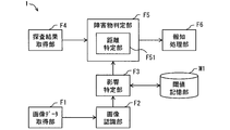
- the periphery monitoring ECU 1 includes an image data acquisition unit F1, an image recognition unit F2, an influence identification unit F3, and an exploration result acquisition unit as functional blocks realized by executing the obstacle notification program.
- F4 the obstacle determination part F5, and the alerting
- the obstacle determination unit F5 includes a distance specifying unit F51 as a finer functional block. Note that some or all of the functional blocks provided in the periphery monitoring ECU 1 may be realized as hardware using one or a plurality of ICs. This periphery monitoring ECU 1 corresponds to an obstacle notification device.
- the threshold value storage unit M1 shown in FIG. 2 is an area that stores data indicating the default threshold value read from the ROM 13 among the storage areas of the RAM 12.
- the default threshold is set to a value corresponding to the elapsed time from the start of transmission of the ultrasonic pulse.
- the default threshold value from the start of transmission of an ultrasonic pulse to the elapse of a predetermined reverberation convergence time Tx is that the transmitted ultrasonic pulse itself and the reverberation of the transmitted ultrasonic pulse are determined from the object. Is set to a sufficiently large value so as not to be erroneously detected as a reflected wave.
- the reverberation here corresponds to an ultrasonic wave generated by vibration from the completion of the transmission of the ultrasonic pulse until the oscillation element stops.
- the reverberation gradually attenuates.
- the time from the start of transmission of an ultrasonic pulse until the reverberation converges, that is, the reverberation convergence time Tx is specified by an actual test, simulation, or the like.
- a broken line L1 in FIG. 3 indicates the transmitted ultrasonic pulse itself and the reception intensity corresponding to the reverberation of the transmitted ultrasonic pulse.
- the default threshold value after the time point when the reverberation convergence time Tx elapses after the transmission of the ultrasonic pulse is started is set to a value Pa assumed as the reception intensity of the reflected wave from the uniform road surface, and a predetermined margin Pb is set.
- a uniform road surface assumed value Pc which is an added value is used.
- the uniform road surface here is a road surface in which the degree of unevenness of the road surface corresponding to the roughness of the pavement is within a predetermined allowable range, and the road surface inclination degree (in other words, the gradient) is uniform. Point to.
- the reception intensity Pa of the reflected wave from the uniform road surface may be specified by an actual test or simulation.
- the predetermined margin Pb is a value for preventing the obstacle determination unit F5 from erroneously determining that an obstacle exists due to a reflected wave from the road surface of the actual road.
- the margin Pb is in consideration of the difference between the unevenness level of the road surface assumed as a uniform road surface and the actual road surface unevenness degree, nonuniformity of the road surface gradient on the actual road (in other words, the degree of curvature), and the like. What is necessary is just to determine suitably.
- the default threshold value may be expressed as a function with the elapsed time T from the start of transmission of the ultrasonic pulse as a variable, or may be expressed in a table format.
- the data indicating the default threshold only needs to be expressed in a format in which the default threshold corresponding to the elapsed time T is uniquely determined.
- a function indicating a correspondence relationship between an elapsed time T from the start of transmission of an ultrasonic pulse and a default threshold is expressed as a program.
- the default threshold value corresponding to a certain elapsed time T is hereinafter also referred to as default threshold ThD (T).
- the image data acquisition unit F1 sequentially acquires image data from the camera 3.
- the image recognizing unit F2 analyzes the image data acquired by the image data acquiring unit F1 to change the road gradient change point (hereinafter referred to as the gradient change point) or the road surface after the gradient change point with respect to the currently running road surface. Recognize relative slopes, road conditions, objects on the road, weather conditions, etc.
- the road surface state includes, for example, whether or not the road surface is paved, the degree of unevenness of the road surface, whether or not it is wet, whether or not there is a puddle, and whether or not there is snow.
- the weather condition means whether it is raining, snowing, hail or the like.
- a known technique may be used as a method for detecting the various elements described above from the image data captured by the camera 3.
- the detection of the gradient change point and the estimation of the relative gradient of the road surface after the gradient change point with respect to the currently running road surface may be performed using, for example, the technique disclosed in Japanese Patent Application Laid-Open No. 2009-133830.
- JP-T-2015-510119 may be used. Whether the road surface is paved, whether it is flooded, whether there is a puddle, whether there is snow, etc. may be implemented with the aid of the technology disclosed in Japanese Patent No. 5720380, for example. Furthermore, what is necessary is just to implement the specification of a weather condition, for example using the technique of patent 4505509.
- the image recognition unit F2 may detect an object (hereinafter referred to as a detection target) preset as a detection target by performing a pattern matching process on the image data. What is necessary is just to set a detection target suitably. For example, walls, guardrails, utility poles, people, road cones, curbs, wheel stops, etc. may be registered as detection objects.
- the image recognition unit F2 determines whether there is a noise element in the detection area of the ultrasonic sensor 2 (in other words, detection of the noise element).
- Noise elements include, for example, road surfaces where the degree of unevenness exceeds a predetermined tolerance, a slope increase point that is a slope change point where the slope increases, a road that extends from the slope increase point, a high road Steps and falling objects whose length is less than a predetermined reference value (for example, several centimeters), flooded roads, puddles, snow accumulation, rainfall, snowfall, rainfall, and the like.
- a predetermined reference value for example, several centimeters
- the elements that are noise elements may be registered in advance.
- the image recognition unit F2 detects an element other than the noise element, but is not limited thereto.
- the image recognition unit F2 only needs to detect at least a noise element. Further, it is not necessary to have a configuration capable of detecting all the above-described noise elements as noise elements. It is only necessary to be able to detect an element of a type that is appropriately defined as a noise element.
- the image recognition unit F2 corresponds to a noise element detection unit.
- the image recognition unit F2 When detecting the noise element, the image recognition unit F2 specifies the area where the noise element exists in the detection area of the ultrasonic sensor 2 and specifies the distance from the ultrasonic sensor 2 to the noise element. .
- the distance between the noise element and the ultrasonic sensor 2 may be calculated as follows, for example.
- the image recognition unit F2 specifies the relative position of the noise element with respect to the host vehicle based on the position of the noise element in the image data and the mounting position and shooting range of the camera 3 in the host vehicle.
- a known technique may be used as a technique for estimating the relative position with respect to the vehicle from the position of the photographed object in the image data photographed by the in-vehicle camera.
- the image recognition unit F2 specifies the distance from the ultrasonic sensor 2 to the noise element based on the mounting position of the ultrasonic sensor 2 in the own vehicle and the relative position of the noise element with respect to the own vehicle.
- the image recognizing unit F2 sequentially provides information on the area where the noise element exists and the distance from the ultrasonic sensor 2 to the noise element to the influence specifying unit F3.
- the influence specifying unit F3 When the image recognition unit F2 detects a noise element in the detection area of the ultrasonic sensor 2, the influence specifying unit F3 returns a reflected wave at the noise element in the elapsed time T from the transmission start timing.
- the noise influence time zone which is a time zone that may come, is specified.
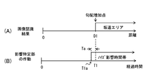
- FIG. 4 shows an operation when the image recognition unit F2 detects a gradient increase point at a point at a distance D1 from the ultrasonic sensor 2 as an example.
- 4A conceptually represents the distance between the gradient increase point detected by the image recognition unit F2 and the ultrasonic sensor 2.
- the influence specifying unit F3 first calculates a round trip flight time T1, which is a time required for the ultrasonic pulse to reciprocate in the section from the ultrasonic sensor 2 to the gradient increase point, based on the distance D1.
- the round trip flight time T1 may be a value obtained by dividing the value obtained by doubling the distance D1 by the speed of sound.
- the influence specifying unit F3 sets a time zone in which the elapsed time T is equal to or longer than the time T1a obtained by subtracting the predetermined error absorption time Ta from the round trip flight time T1 as the noise influence time zone.
- the error absorption time Ta may be a constant set in consideration of an error included in the distance D1 from the ultrasonic sensor 2 calculated by the image recognition unit F2 to the gradient increase point.
- the influence identifying unit F3 when the image recognition unit F2 detects a minute step (hereinafter, a minute step) whose height is less than the reference value at a point where the distance D2 from the ultrasonic sensor 2 is detected. The operation will be described with reference to FIG.
- 5A conceptually represents a distance D2 between the minute step detected by the image recognition unit F2 and the ultrasonic sensor 2.
- the influence identifying unit F3 reciprocates the ultrasonic pulse from the ultrasonic sensor 2 to the minute step based on the distance D2 from the ultrasonic sensor 2 identified by the image recognition unit F2 and the sound speed.
- the round-trip flight time T2 which is the time required for, is calculated.
- a noise influence time zone is defined from a time T2a obtained by subtracting the error absorption time Ta from the round trip flight time T2 to a time T2b obtained by adding the error absorption time Ta to the round trip flight time T2.
- error absorption time Ta for determining the start time point and the end time point of the noise influence time for the area where the noise element exists may be set as appropriate.
- the start time point of the noise influence time zone for the area where the noise element exists may be determined according to the round-trip flight time to the area.
- the end point may be determined depending on the type of the noise element and how far the noise element exists relative to the ultrasonic sensor 2.
- the exploration result acquisition unit F4 sequentially acquires the reception intensity output from the ultrasonic sensor 2.
- the exploration result acquisition unit F4 also acquires a transmission start timing that is a timing at which the ultrasonic sensor 2 starts transmitting an ultrasonic pulse.
- the transmission start timing may be notified from the ultrasonic sensor 2.
- the transmission start timing of the ultrasonic pulse is notified from the functional block that controls the operation of the ultrasonic sensor 2.
- the exploration result acquisition unit F4 may recognize the timing when the input reception intensity is equal to or greater than a predetermined threshold as the transmission start timing.
- the threshold value used for specifying the transmission start timing is a value corresponding to the reception intensity observed at the time of transmitting the ultrasonic pulse, and may be a sufficiently large value so as not to be observed as a reflected wave.
- the obstacle determination unit F5 detects an obstacle based on the reception intensity acquired by the exploration result acquisition unit F4.
- the operation of the obstacle determination unit F5 differs depending on whether or not the image recognition unit F2 detects a noise element in the detection area of the ultrasonic sensor 2. First, a case where the image recognition unit F2 has not detected a noise element in the detection area of the ultrasonic sensor 2 will be described.
- the obstacle determination unit F5 acquires the transmission start timing from the exploration result acquisition unit F4 and progress from the transmission start timing. Time T is measured. The obstacle determination unit F5 determines that there is an obstacle when the currently received reception intensity exceeds the default threshold ThD (T) corresponding to the elapsed time T from the transmission start timing. .
- the obstacle determination unit F5 first acquires the transmission start timing from the search result acquisition unit F4, and from the transmission start timing. The elapsed time T is measured.
- the obstacle determination unit F5 determines whether or not the elapsed time T corresponds to the noise influence time zone specified by the influence specifying unit F3.
- the obstacle determination unit F5 uses the default threshold ThD (T) corresponding to the current elapsed time T to determine whether there is an obstacle. Determine.
- the obstacle determination unit F5 determines a threshold value (hereinafter referred to as a threshold value ThD (T) corresponding to the current elapsed time T).
- a threshold value ThD (T) corresponding to the current elapsed time T.
- the presence / absence of an obstacle is determined using a noise correspondence threshold).
- the threshold used for determining whether there is an obstacle will be hereinafter referred to as a determination threshold.
- the noise correspondence threshold may be dynamically calculated by the obstacle determination unit F5 based on the default threshold, or may be set in advance. When the noise correspondence threshold is set in advance, the set noise correspondence threshold only needs to be stored in the ROM 13 in the same manner as the default threshold.
- the obstacle determination unit F5 dynamically generates a noise corresponding threshold ThN (T) corresponding to the elapsed time T based on the default threshold ThD (T) corresponding to the current elapsed time T. It shall be.
- the noise correspondence threshold ThN (T) corresponding to a certain elapsed time T is a value obtained by multiplying the default threshold ThD (T) corresponding to the elapsed time T by a predetermined coefficient ⁇ .
- the noise correspondence threshold ThN (T) may be a value obtained by adding a predetermined value ⁇ to the default threshold ThD (T). ⁇ may be a positive value.
- the adjustment parameters such as ⁇ and ⁇ may be adjusted according to the type of noise element detected by the image recognition unit F2.
- a value for example, 3 that is smaller than a value (for example, 3) used in the case of an element that is relatively easy to return a reflected wave. 2
- ⁇ Whether or not the element easily returns the reflected wave may be defined in advance for each noise element. The same applies to ⁇ .
- the obstacle determination unit F5 determines that there is an obstacle when the currently received reception intensity exceeds the noise correspondence threshold ThN (T) corresponding to the elapsed time T from the transmission start timing. To do.
- the obstacle determination unit F5 uses the default threshold ThD (T) when the image recognition unit F2 has not detected a noise element in the detection area of the ultrasonic sensor 2. Is detected.
- the obstacle determination unit F5 uses the noise correspondence threshold ThN (T).
- the obstacle determination unit F5 when the obstacle determination unit F5 detects an obstacle, the obstacle determination unit F5 specifies the distance between the detected obstacle and the ultrasonic sensor 2.
- the distance specifying unit F51 included in the obstacle determining unit F5 is a functional block that specifies the distance between the obstacle and the ultrasonic sensor 2.
- the distance specifying unit F51 specifies the distance from the ultrasonic sensor 2 to the obstacle by multiplying the elapsed time from the transmission start timing to the detection of the obstacle by the sound speed and dividing by 2.
- the notification processing unit F6 cooperates with the notification device 4 to perform processing (hereinafter referred to as notification processing) for notifying the driver of the host vehicle that there is an obstacle ahead of the host vehicle. For example, when the notification device 4 is a display, the notification processing unit F6 displays an image or text in which an obstacle exists in front of the host vehicle. In addition, when the notification device 4 is a speaker, the notification processing unit F6 outputs a voice message or a warning sound indicating that an obstacle exists in front of the host vehicle.
- the notification processing unit F6 notifies the driver that there is an obstacle by vibrating the vibrator as the notification device 4 with a predetermined vibration pattern.
- the vibrator may be provided in a portion that contacts the driver's body, such as the driver's seat or handle. That is, the notification processing unit F6 performs the notification process in a manner corresponding to the notification device 4.
- Information indicating that there is an obstacle ahead of the host vehicle may be output in a manner that can be perceived by humans, such as image display, text display, light emission, vibration, and sound (including simple sounds).
- the conditions for the notification processing unit F6 to perform the notification processing may be set as appropriate.
- the notification process may be performed when an obstacle exists within a certain distance from the ultrasonic sensor 2.
- the notification process may be performed regardless of the distance between the obstacle and the ultrasonic sensor 2.
- the notification process may be performed based on the fact that the obstacle determination unit F5 detects an obstacle.
- threshold determination process for the obstacle determination unit F5 to determine the noise influence threshold will be described using the flowchart shown in FIG. 6 may be executed sequentially (for example, every 100 milliseconds) when the vehicle is in a power supply state where the vehicle can run.
- step S101 the image data acquisition unit F1 acquires the image data generated by the camera 3, and proceeds to step S102.
- the image recognition unit F2 performs image recognition processing using the image data acquired in step S101, thereby detecting various elements such as presence / absence of a change in road surface gradient, road surface condition, and weather condition. .
- step S102 the process proceeds to step S103.
- the image recognition process is performed for each frame taken by the camera 3, but the present invention is not limited to this.
- Image recognition processing may be performed using image data of a plurality of frames. For example, as a mode of generating a super-resolution image with improved resolution by using a well-known super-resolution technique based on image data for three consecutive frames, and detecting various elements from the super-resolution image Also good.
- step S103 the image recognition unit F2 determines whether or not a noise element exists in the detection area of the ultrasonic sensor 2 as a result of the image recognition processing in step S102. If a noise element is detected in the detection area of the ultrasonic sensor 2, an affirmative determination is made in step S103 and the process proceeds to step S104. On the other hand, when a noise element is not detected in the detection area of the ultrasonic sensor 2, a negative determination is made in step S103, and the process proceeds to step S105.
- step S104 the influence specifying unit F3 specifies the noise influence time zone. Then, the obstacle determination unit F5 generates the noise correspondence threshold ThN (T) used in the noise influence time zone based on the default threshold ThD (T), and ends this flow. In step S105, the default threshold value is adopted as the determination threshold value, and this flow ends.
- the obstacle determination unit F5 detects an obstacle using a default threshold when the image recognition unit F2 does not detect a noise element in the detection area of the ultrasonic sensor 2.
- the obstacle determination unit F5 detects a noise element in the detection area of the ultrasonic sensor 2 and the elapsed time T corresponds to the noise influence time zone.
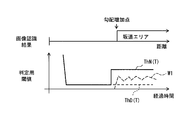
- the reflected wave from the road surface extending farther than the slope increasing point returns.
- a noise corresponding threshold value ThN (T) larger than the default threshold value ThD (T) is applied. Therefore, it is possible to reduce the possibility of erroneous determination that an obstacle exists due to the reflected wave from the road surface.
- the broken line W1 in FIG. 7 conceptually represents the transition of the received intensity of the reflected wave from the road surface.
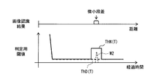
- the default threshold for determining a time zone in which a reflected wave from the minute step is expected to return is the default.
- a noise correspondence threshold ThN (T) larger than the threshold ThD (T) is applied. Therefore, it is possible to reduce the possibility of erroneous determination that an obstacle exists due to the reflected wave from the minute step.
- the broken line W2 in FIG. 8 conceptually represents the transition of the reception intensity of the reflected wave from the minute step.
- the noise correspondence threshold is larger than the default threshold
- using the noise mode threshold as the determination threshold corresponds to adopting a condition that is less likely to be satisfied as a condition for determining that an obstacle exists. . That is, in the embodiment described above, when a noise element is detected, whether or not an obstacle exists using a condition that is less likely to be satisfied than a condition used when the noise element is not detected. This corresponds to an example of a mode for determining whether or not.
- the obstacle determination unit F5 determines the presence or absence of an obstacle using a default threshold value. Further, even when there is a noise element, the obstacle determination unit F5 determines the presence or absence of an obstacle using a default threshold in a time zone that does not correspond to the noise influence time zone.
- the default threshold value to a relatively small value in advance, it is possible to detect the presence of an obstacle with a relatively high sensitivity in a situation that is not affected by noise elements. That is, according to the above configuration, it is possible to increase obstacle detection sensitivity while suppressing unnecessary notification.
- the time zone corresponding to the region far from the ultrasonic sensor 2 tends to receive the reflected wave from the noise element with a stronger reception intensity. This is because as the elapsed time from the transmission start timing increases, the ultrasonic pulse spreads and propagates through the space, and is reflected and returned by various elements.
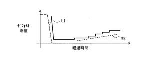
- the default threshold is set to a larger value as the elapsed time becomes larger, as shown in FIG. Assumed (this is assumed configuration).
- the broken line W3 in FIG. 9 has shown the assumed value (henceforth an assumed noise level) of the receiving intensity of the reflected wave by a noise element according to elapsed time.
- the detection sensitivity of an obstacle existing at a position away from the ultrasonic sensor 2 decreases. That is, if the default threshold is set to be larger than the assumed noise level, the range in which an obstacle can be detected becomes narrower in terms of software.
- the determination threshold when a noise element is present, the determination threshold is changed so that erroneous detection of an obstacle due to the noise element is suppressed. Therefore, according to the configuration of the present embodiment, the default threshold value of the time zone corresponding to the far region can be set to a value smaller than the assumed configuration. That is, a software-like (in other words, logical) detection area can be formed larger than the assumed configuration.
- the obstacle determination unit F5 may be provided in the ultrasonic sensor 2.
- the default threshold after the reverberation convergence time Tx is set to a constant value.
- the present invention is not limited to this. Similar to the assumed configuration, the default threshold value may be set to a large value according to the elapsed time T from the transmission start timing.
- the noise influence time zone is specified as in the first embodiment, and when the elapsed time T is the noise influence time zone, the noise correspondence threshold may be applied as the determination threshold. .
- the influence specifying unit F3 specifies the noise influence time zone corresponding to the area where the noise element exists. To do.
- the obstacle determination part F5 implements the presence or absence of an obstacle using the noise corresponding
- the solid line in FIG. 10 represents the threshold value used for determination, and the broken line represents the default threshold value.
- the time zone other than the noise influence time zone is a time zone in which the reflected wave from the noise element is relatively low. Therefore, when the default threshold ThD (T) is set so as to exceed the assumed noise level, a value smaller than the default threshold ThD (T) is set as a threshold for determination in a time zone other than the noise affected time zone. It may be adopted to determine whether there is an obstacle.
- the noise suppression threshold is adopted as the determination threshold value, while in a time zone other than the noise influence time zone, a value lower than the default threshold ThD (T) is used.
- ThD used as a threshold for determination.
- the value used as the determination threshold value in the time zone other than the noise influence time zone may be, for example, the uniform road surface assumed value Pc.
- FIG. 11 shows a case where a minute step is detected as a noise element and the time zone from the elapsed time T3a to T3b is specified as the noise influence time zone.
- the elapsed time T3 represents the round trip flight time corresponding to the distance D3 from the ultrasonic sensor 2 to the minute step.
- the default threshold value is defined so as to increase with the elapsed time T, if it is not affected by the noise element, a smaller threshold value is used.
- the presence or absence of an object can be determined. That is, the range in which an obstacle can be detected can be expanded in software as compared with the first modification.
- zone was specified and the value larger than a default threshold value was applied as a threshold value for determination of a noise influence time slot
- the noise correspondence threshold ThN (T) may be applied to all elapsed times after the reverberation convergence time Tx.
- the noise corresponding threshold value ThN (T) may be applied even in a time zone shorter than the reverberation convergence time Tx. That is, when the image recognition unit F2 detects a noise element, the noise correspondence threshold ThN (T) may be applied in all time zones. According to such an aspect, the process for specifying a noise influence time zone can be omitted.
- the periphery monitoring ECU 1 in the second embodiment includes an image data acquisition unit F1, an image recognition unit F2, an exploration result acquisition unit F4, an obstacle determination unit F5, and a notification processing unit F6 as functional blocks.
- the obstacle determination unit F5 includes a distance specifying unit F51 and a reflection detection unit F52 as finer functional blocks.
- the threshold storage unit M1 stores a default threshold ThD (T) corresponding to the elapsed time T from the transmission start timing.
- the reflector detection unit F52 is a functional block that detects a reflector that is an object that reflects an ultrasonic pulse based on the reception intensity provided from the search result acquisition unit F4. More specifically, the reflector detection unit F52 acquires the transmission start timing from the search result acquisition unit F4, and measures the elapsed time T from the transmission start timing. Then, the reflector detection unit F52 determines that there is a reflector when the currently received reception intensity exceeds the default threshold ThD (T) corresponding to the elapsed time T from the transmission start timing. .
- ThD ThD
- the distance specifying unit F51 is based on the time required from the transmission start timing until the reflecting object detection unit F52 detects the reflecting object, in other words, the elapsed time T when the reflecting object detection unit F52 detects the reflecting object. Then, the distance to the detected reflector is specified. The specified distance is temporarily stored in the RAM 12.
- the obstacle determination unit F5 determines that an obstacle is present when a reflection object is detected at a distance that can be regarded as the same distance continuously for a predetermined number of times. The number of determinations used here is changed depending on whether or not the image recognition unit F2 detects a noise element in the detection area of the ultrasonic sensor 2.
- the fixed number of times adopted when the image recognition unit F2 has not detected a noise element in the detection area of the ultrasonic sensor 2 is the first fixed number of times, and the image recognition unit F2 has noise in the detection area of the ultrasonic sensor 2.
- the fixed number of times adopted when the element is detected is referred to as a second fixed number of times.
- the first determination number and the second determination number may be set as appropriate.
- the first fixed number of times is 3 times and the second fixed number of times is 5 times.
- the second determined number may be a value larger than the first determined number.
- the first fixed number of times corresponds to the first specified number of times
- the second fixed number of times corresponds to the second fixed number of times.
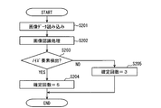
- the outline of the operation of the periphery monitoring ECU 1 in the second embodiment will be described with reference to the flowchart shown in FIG.
- the flowchart shown in FIG. 13 may be executed sequentially (for example, every 100 milliseconds) when the vehicle is in a power supply state where the vehicle can run.
- step S201 to step S203 is the same as the processing from step S101 to step S103 in the flowchart shown in FIG.
- step S203 it is determined whether or not there is a noise element in the detection area of the ultrasonic sensor 2. If it is determined in step S203 that a noise element is present in the detection area of the ultrasonic sensor 2, an affirmative determination is made in step S203, and the process proceeds to step S204. On the other hand, when it is not determined that a noise element exists in the detection area of the ultrasonic sensor 2, a negative determination is made in step S203, and the process proceeds to step S205.
- step S204 the obstacle determination unit F5 adopts the second fixed number of times as the fixed number of times and ends this flow.
- the first determination count is adopted as the determination count, and this float is finished.
- the number of determinations used to determine that an obstacle is present is set to be higher than that when no noise element is detected.
- the reception intensity of a reflected wave from a noise element can be expected to vary every time an ultrasonic pulse is transmitted. Therefore, by increasing the number of determinations, it is possible to reduce the risk of determining that a noise element detected as a reflection object is an obstacle. That is, according to the above configuration, the same effect as that of the first embodiment can be obtained.
- using the second fixed number of times larger than the first fixed number as the number of fixed times for determining that an obstacle is present means adopting a condition that is less likely to be satisfied as a condition for determining that an obstacle is present. It corresponds to doing. That is, in the second embodiment described above, when a noise element is detected, there is an obstacle using a condition that is less likely to be satisfied than a condition used when the noise element is not detected. This corresponds to an example of a mode for determining whether or not there is.
- This third embodiment also includes a periphery monitoring ECU 1, an ultrasonic sensor 2, a camera 3, and a notification device 4, as in the above-described embodiments and modifications thereof.
- the periphery monitoring ECU 1 in the present embodiment includes an image data acquisition unit F1, an image recognition unit F2, an exploration result acquisition unit F4, an obstacle determination unit F5, a notification processing unit F6, and an output as functional blocks.
- a level adjustment unit F7 is provided.
- the output level adjustment unit F7 changes the signal intensity (hereinafter, output level) of the ultrasonic pulse transmitted by the ultrasonic sensor 2.
- the ultrasonic sensor 2 in the present embodiment has a configuration capable of adjusting the output level of the ultrasonic pulse.
- the ultrasonic sensor 2 has a configuration that can be set to two levels of an ultrasonic pulse output level: a preset rated level and a suppression level smaller than the rated level.
- the suppression level only needs to be smaller than the rated level, and may be set as appropriate.
- the ROM 13 stores data indicating a detection area when the output level of the ultrasonic sensor 2 is the rated level.
- the change of the output level may be realized by adjusting the driving voltage of the ultrasonic sensor 2. Further, the output level may be reduced by setting the frequency of the signal input to the oscillation element to a value shifted from the resonance frequency of the oscillation element by a certain amount (hereinafter referred to as suppression frequency).
- the suppression frequency is a frequency at which the output level becomes the suppression level.
- the operation of the output level adjustment unit F7 will be described using the flowchart shown in FIG.
- the flowchart shown in FIG. 15 may be executed sequentially (for example, every 100 milliseconds) when the vehicle is in a power supply state where it can travel.
- step S301 to step S303 is the same as the processing from step S101 to step S103 in the flowchart shown in FIG.
- step S303 it is determined whether or not a noise element exists in the detection area when the output level of the ultrasonic sensor 2 is the rated level. If it is determined in step S303 that a noise element is present, an affirmative determination is made in step S303, and the process proceeds to step S304. On the other hand, if it is not determined that a noise element is present in the detection area of the ultrasonic sensor 2, a negative determination is made in step S303, and the process proceeds to step S305.
- step S304 the output level adjustment unit F7 sets the output level to the suppression level and ends this flow.
- step S305 the output level is set to the rated level, and this flow ends.
- the ultrasonic pulse when the image recognition unit F2 does not detect the noise element, the ultrasonic pulse is transmitted at the rated level. On the other hand, when the noise element is detected, the ultrasonic pulse is transmitted at the suppression level. Send it. Decreasing the output level corresponds to reducing the detection area of the ultrasonic sensor 2. That is, the obstacle notification system 100 according to the present embodiment makes the detection area smaller when the image recognition unit F2 detects a noise element than when a noise element is not detected.
- an ultrasonic sensor is used as a sensor for detecting an obstacle existing around the host vehicle (hereinafter referred to as an obstacle sensor), but the present invention is not limited thereto.
- the obstacle sensor may be a millimeter wave radar that uses millimeter waves (including quasi-millimeter waves) as a search wave, a laser radar that uses light as a search wave, and the like. That is, the exploration wave transmission / reception device may be a device other than the ultrasonic sensor, such as a millimeter wave radar or a laser radar.
- the obstacle notification device is mounted on a vehicle, and transmits a search wave in the traveling direction of the vehicle, and a search wave transmission / reception device that receives a reflected wave returned by the search wave reflected by an object.
- An object to be notified to the driver of the vehicle using the search result acquisition unit (F4) that sequentially acquires the reception intensity of the received reflected wave and the reception intensity of the reflected wave acquired by the search result acquisition unit The obstacle determination unit (F5) that determines whether or not an obstacle is present in the traveling direction of the vehicle, and the driver is determined based on the fact that the obstacle determination unit determines that an obstacle exists.
- the image processing unit (F6) that performs a notification process for notifying the presence of the obstacle, and image data captured by a camera that includes the arrival range of the exploration wave transmitted by the exploration wave transmission / reception device in the photographing range.
- a noise element detection unit (F2) that detects the presence of a noise element that is a set element. When the noise element detection unit detects a noise element, the obstacle determination unit uses a condition that is less likely to be satisfied than the condition used when the noise element detection unit does not detect the noise element. It is determined whether or not exists.
- the noise element detection unit detects the noise element by analyzing the image data of the camera.
- the obstacle determination unit uses the condition that is less likely to be satisfied than the condition used when the noise element is not detected. It is determined whether or not.
- the obstacle notification device is mounted on a vehicle and transmits a search wave in the traveling direction of the vehicle, and the search wave transmission / reception device that receives the reflected wave reflected by the object is received.
- a search result acquisition unit (F4) that sequentially acquires the reception intensity of the reflected wave, a default threshold that is set in advance to determine that there is an obstacle that should be notified to the driver of the vehicle, and acquisition of the search result
- the obstacle determination unit (F5) determines that an obstacle is present when the reflected wave exceeds the default threshold by comparing the received intensity of the reflected wave acquired by the unit with the obstacle determination unit.
- a notification processing unit (F6) that performs notification processing for notifying the driver of the presence of the obstacle, and the exploration wave transmitting / receiving device transmit
- An image data acquisition unit (F1) that acquires image data captured by a camera that includes the exploration wave reachable range in the imaging range, and an element that can reflect the exploration wave by analyzing the image data acquired by the image data acquisition unit
- the noise element detection unit (F2) that detects the presence of a noise element that is an element set in advance as an element that does not need to be notified to the driver of the vehicle, and the noise element detection unit includes noise.
- the output for adjusting the output level of the exploration wave When detecting the element, the output for adjusting the output level of the exploration wave to a level smaller than the rated level set in advance as the output level used when the noise element detection unit does not detect the noise element A level adjustment unit (F7).
- the exploration wave transmitting / receiving device transmits the exploration wave at the output level set by the output level adjustment unit.
- the exploration wave transmitting / receiving apparatus transmits the exploration wave at a predetermined rated level when the noise element is not detected by the noise element detection unit, and when the noise element is detected. Transmit the exploration wave at an output level smaller than the rated level.
- the output level is reduced, naturally the received intensity of the reflected wave from the noise element also decreases. Therefore, it is possible to reduce the possibility of erroneous determination that an obstacle exists by receiving a reflected wave from a noise element. As a result, the possibility of performing unnecessary notification can be reduced.
- Obstacle notification system 1: Perimeter monitoring ECU (obstacle notification device), 2: Ultrasonic sensor (probing wave transmission / reception device), 3: Camera, 4: Notification device, 11: CPU, 12: RAM, 13: ROM, F1: Image data acquisition unit, F2: Image recognition unit (noise element detection unit), F3: Influence specifying unit, F4: search result acquisition unit, F5: obstacle determination unit, F6: notification processing unit, F7: output level adjustment unit, F51: distance specifying unit, F52: reflector detection unit, M1 threshold storage unit
Landscapes
- Engineering & Computer Science (AREA)
- Radar, Positioning & Navigation (AREA)
- Remote Sensing (AREA)
- Physics & Mathematics (AREA)
- General Physics & Mathematics (AREA)
- Computer Networks & Wireless Communication (AREA)
- Automation & Control Theory (AREA)
- Acoustics & Sound (AREA)
- Mechanical Engineering (AREA)
- Human Computer Interaction (AREA)
- Transportation (AREA)
- Traffic Control Systems (AREA)
- Measurement Of Velocity Or Position Using Acoustic Or Ultrasonic Waves (AREA)
- Multimedia (AREA)
Abstract
探査波送受信装置が送信する探査波の到達範囲を撮影範囲に含むカメラが撮影した画像の画像データを取得し、取得した画像データを解析することで、探査波を反射しうる要素であって、かつ、ドライバに対して報知する必要がない要素として予め設定されている要素であるノイズ要素の存在を検出する障害物報知装置であって、ノイズ要素を検出している場合には、ノイズ要素を検出していない場合に用いる条件よりも充足されにくい条件を用いて、障害物が存在しているか否かを判定する。
Description
本発明は、車両周辺に存在する障害物についての情報をドライバに対して報知する障害物報知装置に関する。
従来、所定の探査波を送受信することで車両の進行方向に存在する障害物を検出し、障害物の存在をドライバに知らせる装置(以降、障害物報知装置)が知られている。
例えば、特許文献1に開示の障害物報知装置は、探査波としての超音波パルスを送受信する超音波センサを用いて、車両の進行方向に存在する障害物と車両の距離を検出する。そして、その検出している障害物と車両との距離が所定の閾値未満となった場合に、警報音等の出力によって、当該障害物の存在をドライバに報知する。なお、ここでの障害物とは、種々の物体のうち、ドライバに対してその存在を報知すべき物体を指す。例えば、車両の進行を妨げるほどの大きさを有する物体が障害物として想定されればよい。
このような障害物報知装置においては、障害物を検出するためのセンサ(以降、障害物センサ)として、超音波センサ以外にも、探査波としてミリ波(準ミリ波を含む)を用いるミリ波レーダ等、様々なセンサが用いられる。
障害物センサは、探査波を送信するとともに、その探査波の到達範囲内に存在する物体で反射された反射波を受信する。そして、その受信した反射波の受信強度が、予め設定された、障害物が存在すると判定するための閾値(以降、判定用閾値)を超過している場合に、障害物が存在すると判定する。障害物が存在すると判定することは、障害物を検出することに相当する。
なお、障害物が存在するか否かの判定は、障害物センサ自体が実施する場合もあれば、障害物センサの外部に存在する電子制御装置が、障害物センサから受信強度を示す情報を取得することで実施する場合もある。便宜上、障害物センサ又は電子制御装置が備える、障害物が存在するか否かの判定を実施する機能モジュールを、障害物判定部と称する。障害物判定部は、1つ又は複数のICを用いてハードウェアとして実現されてもよいし、CPUが所定のソフトウェアを実行することで実現されてもよい。
障害物センサが送信した探査波は、障害物だけでなく、例えば路面等の、本来ドライバにその存在を報知する必要がない物体(以降、ノイズ要素)でも反射されて障害物センサに返ってくる。そのため、判定用閾値を小さくし過ぎると、ノイズ要素からの反射波によって障害物が存在すると誤判定する可能性が高まってしまう。一方で、判定用閾値を高くし過ぎると、本来ドライバに対してその存在を報知すべき物体(つまり障害物)の検出が遅れたり、検出できなくなってしまったりするおそれが生じる。
そこで、従来の障害物報知装置では、傾斜度合いが一様な路面(以降、一様路面)からの反射波の受信強度として想定される値を試験等によって特定し、判定用閾値を、一様路面からの反射波が超過しにくい値に設定していた。そのような態様によれば、車両が一様路面に存在する状況において、障害物判定部が一様路面からの反射波によって障害物が存在すると誤判定するおそれを低減できるためである。
しかしながら、車両が走行する環境は、一様路面だけではない。車両が実際に走行する道路上には、傾斜度合いが変化する地点も存在する。仮に車両が略水平な道路上の、登り坂が始まる手前の地点に存在する場合、障害物判定部が、その上り坂の路面を障害物であると誤判定してしまうおそれがある。上り坂の路面は、車両が存在している路面に対して隆起しているため、車両に向けて探査波を反射しやすいためである。
また、道路の傾斜度合いの変化だけでなく、舗装の粗さに対応する路面の凹凸や、道路上の微小な段差、雨、雪などによっても、障害物の誤検出は生じうる。障害物センサが物体を誤検出してしまうと、その誤検出に基づいて障害物の存在を知らせるための警報が実施されてしまい、乗員に違和感や不快感を与えてしまうおそれがある。
一実施形態は、障害物の存在をドライバに対して報知する障害物報知装置において、不要な報知を実施するおそれを抑制できる障害物報知装置を提供する。
実施形態の障害物報知装置は、車両に搭載され、前記車両の進行方向に探査波を送信するとともに、その探査波が物体によって反射されて返ってくる反射波を受信する探査波送受信装置が受信した前記反射波の受信強度を逐次取得する探査結果取得部と、前記探査結果取得部が取得した前記反射波の受信強度を用いて、前記車両のドライバに対してその存在を報知すべき物体である障害物が、前記車両の進行方向に存在しているか否かを判定する障害物判定部と、前記障害物判定部によって前記障害物が存在すると判定されていることに基づいて、前記ドライバに対して当該障害物の存在を報知するための報知処理を実施する報知処理部と、前記探査波送受信装置が送信する前記探査波の到達範囲を撮影範囲に含むカメラが撮影した画像の画像データを取得する画像データ取得部と、前記画像データ取得部が取得した前記画像データを解析することで、前記探査波を反射しうる要素であって、かつ、前記ドライバに対して報知する必要がない要素として予め設定されている要素であるノイズ要素の存在を検出するノイズ要素検出部と、を備える。前記障害物判定部は、前記ノイズ要素検出部が前記ノイズ要素を検出している場合には、前記ノイズ要素検出部が前記ノイズ要素を検出していない場合に用いる条件よりも充足されにくい条件を用いて、前記障害物が存在しているか否かを判定する。
[第1実施形態]
以下、本発明の第1実施形態を図面に基づいて説明する。図1に示す障害物報知システム100は、車両に搭載されてあって、周辺監視ECU1、超音波センサ2、カメラ3、及び報知装置4を備える。以降では、障害物報知システム100が搭載された車両を自車両と称する。なお、ECUは、Electronic Control Unitの略である。
以下、本発明の第1実施形態を図面に基づいて説明する。図1に示す障害物報知システム100は、車両に搭載されてあって、周辺監視ECU1、超音波センサ2、カメラ3、及び報知装置4を備える。以降では、障害物報知システム100が搭載された車両を自車両と称する。なお、ECUは、Electronic Control Unitの略である。
障害物報知システム100は、自車両の進行方向に存在する障害物についてドライバに報知するためのシステムである。ここでは一例として、障害物報知システム100は、自車両が前進している場合に、自車両の前方に存在する障害物についてドライバに報知するものとする。もちろん他の態様として、障害物報知システム100は、自車両が後退している場合に自車両の後方に存在する障害物についてドライバに報知するものであってもよい。その場合には、自車両の後方に存在する障害物についてドライバに報知できるように、超音波センサ2やカメラ3の設置位置や設置姿勢等を調整すればよい。なお、ここでの障害物とは、ドライバにその存在を報知すべき物体であり、例えば、自車両の進行を妨げるほどの大きさを有する物体を指す。以下、本実施形態における障害物報知システム100の構成について述べる。
<障害物報知システムの概略的な構成>
周辺監視ECU1は、車両内に構築されたローカルエリアネットワーク(以降、LAN:Local Area Network)5を介して、超音波センサ2、カメラ3、及び報知装置4のそれぞれと相互通信可能に接続されている。周辺監視ECU1は、障害物報知システム100全体の動作を制御する。この周辺監視ECU1の詳細については後述する。
周辺監視ECU1は、車両内に構築されたローカルエリアネットワーク(以降、LAN:Local Area Network)5を介して、超音波センサ2、カメラ3、及び報知装置4のそれぞれと相互通信可能に接続されている。周辺監視ECU1は、障害物報知システム100全体の動作を制御する。この周辺監視ECU1の詳細については後述する。
超音波センサ2は、探査波としての超音波パルスを、所定の送信周期で送信するとともに、送信した超音波パルスが自車両外部に存在する物体で反射されて返ってきた反射波を受信する。そして、超音波センサ2は、受信した反射波の信号強度を示す信号を周辺監視ECU1に逐次出力する。超音波センサ2が探査波送受信装置に相当する。
超音波パルスの送信と、反射波の受信は、1つの発振素子を用いて実現されればよい。もちろん、他の態様として、送信用の発振素子とは別に、受信用の発振素子を1つ又は複数備える態様としてもよい。送信周期は、たとえば、数百ミリ秒とすればよい。ここでは一例として送信周期は100ミリ秒とする。
この超音波センサ2は、自車両の前方に超音波パルスを送信するように、自車両において適宜設定される位置(例えばフロントバンパ)に設置されていればよい。ここでの前方とは、車両の正面方向だけでなく、斜め前方も含む。正面方向とは、自車両後端部から自車両前端部へと向かう方向である。
ここでは一例として超音波センサ2は、指向性の中心となる方向が自車両の正面方向と一致するように設けられている。他の態様として、超音波センサ2の指向性の中心方向は、車両正面方向から車幅方向に30°程度傾くように設置されていてもよい。
超音波センサ2の指向性や、送信する超音波パルスの強度は、所望の検知エリアを形成するように調整されればよい。検知エリアとは、障害物を検知可能な範囲である。超音波センサ2が所定の大きさの物体からの反射波を所定の受信強度で受信可能な範囲が、検知エリアに相当する。この検知エリアが到達範囲に相当する。なお、超音波センサ2は、複数設けられていてもよい。
カメラ3は、光学式のカメラである。例えばカメラ3は、CMOSカメラやCCDカメラ等を用いて実現されればよい。カメラ3は、自車両前方の所定範囲を撮影するように、ウインドシールド上端部近傍(例えばルームミラー付近)に設置されている。便宜上、以降ではカメラ3が撮影する範囲を撮影範囲とも称する。カメラ3が撮影した画像のデータ(以降、画像データ)は逐次周辺監視ECU1に提供される。
なお、カメラ3の設置位置は、適宜設定されればよく、ルームミラー付近に限らない。カメラ3は、車両前方に対するドライバの視界を遮らない位置に取り付けられればよい。ただし、カメラ3は、その撮影範囲が超音波センサ2の検知エリアを包含するように設置されているものとする。
また、本実施形態では一例としてカメラ3は光学式のカメラとするが、他の態様としてカメラ3は、赤外線カメラや近赤外線カメラなどであってもよい。さらに、カメラ3はステレオカメラであってもよい。
報知装置4は、周辺監視ECU1からの指示に基づいて、自車両の進行方向(ここでは前方)に障害物が存在することを示す情報を、ドライバが知覚可能な態様で出力する。この報知装置4としては、ディスプレイや、LED等のインジケータ、スピーカ、バイブレータ等を用いることができる。
<周辺監視ECU1の構成及び作動について>
周辺監視ECU1は、コンピュータとして構成されており、CPU11、RAM12、ROM13、I/O、及び、これらの構成を接続するバスラインなどを備えている。ROM13には、通常のコンピュータを本実施形態における周辺監視ECU1として機能させるためのプログラム(以降、障害物報知用プログラム)等が格納されている。
周辺監視ECU1は、コンピュータとして構成されており、CPU11、RAM12、ROM13、I/O、及び、これらの構成を接続するバスラインなどを備えている。ROM13には、通常のコンピュータを本実施形態における周辺監視ECU1として機能させるためのプログラム(以降、障害物報知用プログラム)等が格納されている。
また、ROM13には、超音波センサ2やカメラ3に関する設定データも格納されている。超音波センサ2に関する設定データとは、自車両における超音波センサ2の設置位置や検知エリアなどを示すデータである。カメラ3に関する設定データとは、カメラ3の設置位置や撮影範囲などを示すデータである。さらに、ROM13には、超音波センサ2から提供される受信強度に基づいて障害物が存在するか否かを判定するために用いられる閾値として予め設定されているデフォルト閾値も格納されている。
なお、上述の障害物報知用プログラムは、ROM等の非遷移的実体的記録媒体(non- transitory tangible storage medium)に格納されていればよい。CPU11が障害物報知用プログラムを実行することは、障害物報知用プログラムに対応する方法が実行されることに相当する。
周辺監視ECU1は、上述の障害物報知用プログラムを実行することによって実現する機能ブロックとして、図2に示すように、画像データ取得部F1、画像認識部F2、影響特定部F3、探査結果取得部F4、障害物判定部F5、及び、報知処理部F6を備える。また、障害物判定部F5は、より細かい機能ブロックとして、距離特定部F51を備える。なお、周辺監視ECU1が備える機能ブロックの一部又は全部は、一つあるいは複数のIC等を用いてハードウェアとして実現してもよい。この周辺監視ECU1が障害物報知装置に相当する。
図2に示す閾値記憶部M1は、RAM12が備える記憶領域のうち、ROM13から読み出されたデフォルト閾値を示すデータを記憶している領域である。本実施形態において、デフォルト閾値は、図3に示すように、超音波パルスの送信を開始してからの経過時間に応じた値が設定されている。
具体的には、超音波パルスの送信を開始してから所定の残響収束時間Tx経過するまでのデフォルト閾値は、送信した超音波パルスそれ自体と、その送信した超音波パルスの残響を、物体からの反射波として誤検出しないために、十分に大きい値に設定されている。
なお、ここでの残響とは、超音波パルスの送信を完了してから発振素子が静止するまでの振動によって発生する超音波に相当する。残響は徐々に減衰していく。超音波パルスの送信を開始してから残響が収束するまでの時間、つまり残響収束時間Txは、実試験やシミュレーション等によって特定されている。なお、図3における破線L1は、送信した超音波パルスそれ自体と、その送信した超音波パルスの残響に対応する受信強度を示している。
また、超音波パルスの送信を開始してから残響収束時間Txが経過する時点以降におけるデフォルト閾値は、一様路面からの反射波の受信強度として想定される値Paに、所定の裕度Pbを加えた値である一様路面想定値Pcとする。ここでの一様路面とは、舗装の粗さに対応する路面の凹凸度合いが所定の許容範囲内であり、かつ、路面の傾斜度合い(換言すれば勾配)が一様となっている路面を指す。
一様路面からの反射波の受信強度Paは、実試験やシミュレーションによって特定されればよい。所定の裕度Pbは、実際の道路の路面からの反射波によって、障害物が存在すると障害物判定部F5が誤判定することを抑制するための値である。裕度Pbは、一様路面として想定した路面の凹凸度合いと実際の路面の凹凸度合いとの違いや、実際の道路における路面の勾配の不均一性(換言すれば湾曲の度合い)等を鑑みて適宜決定されればよい。
デフォルト閾値は、超音波パルスの送信を開始してからの経過時間Tを変数とした関数として表されていてもよいし、テーブル形式で表されていてもよい。デフォルト閾値を示すデータは、経過時間Tに対応するデフォルト閾値が一意に定まる形式で表されていればよい。ここでは一例として、超音波パルスの送信を開始してからの経過時間Tとデフォルト閾値との対応関係を示す関数が、プログラムとして表現されているものとする。便宜上、以降において、或る経過時間Tに対応するデフォルト閾値を、デフォルト閾値ThD(T)とも記載する。
次に種々の機能ブロックについて述べる。画像データ取得部F1は、カメラ3から画像データを逐次取得する。画像認識部F2は、画像データ取得部F1が取得した画像データを解析することで、道路勾配の変化点(以降、勾配変化点)や、現在走行している路面に対する勾配変化点以降の路面の相対的な勾配、路面の状態、路面上の物体、天候状態等を認識する。
ここでの路面状態とは、例えば、路面が舗装されているか否か、路面の凹凸度合い、被水しているか否か、水たまりが存在するか否か、積雪の有無を含む。また、天候状態とは、雨、雪、雹等が降っているか否かを意味する。
カメラ3が撮影した画像データから上述した種々の要素を検出する方法は、周知の技術を用いればよい。勾配変化点の検出や、現在走行している路面に対する勾配変化点以降の路面の相対的な勾配の推定は、例えば、特開2009-133830号に開示の技術を用いて実施すればよい。
路面の凹凸度合いの特定には、例えば特表2015-510119号に開示を用いればよい。路面が舗装されているか否か、被水しているか否か、水たまりが存在するか否か、積雪の有無などは、例えば特許第5720380号に開示の技術を援用して実施すればよい。さらに、天候状態の特定は、例えば、特許第4505509号に開示の技術を用いて実施すればよい。
また、画像認識部F2は、画像データに対してパターンマッチング処理を行うことによって、検出対象として予め設定されている物体(以降、検出対象物)を検出してもよい。検出対象物は適宜設定されればよい。例えば、壁やガードレール、電柱、人物、ロードコーン、縁石、輪留めなどを検出対象物として登録しておけばよい。
ところで、画像認識部F2が画像データから検出する種々の物体や環境の中には、超音波パルスを反射しうる要素であって、かつ、車両のドライバに対して報知する必要がない要素(以降、ノイズ要素)も含まれる。画像認識部F2は、超音波センサ2の検知エリア内にノイズ要素が存在するか否かの判定(換言すれば、ノイズ要素の検出)も行う。
ノイズ要素とは、例えば、凹凸度合いが所定の許容範囲以上となっている路面や、勾配が大きくなる勾配変化点である勾配増加点、その勾配増加点から先に延設されている道路、高さが所定の基準値(例えば数センチ)未満の段差及び落下物、被水している道路、水溜り、積雪、降雨、降雪、降雹等である。
画像認識部F2が認識可能な要素のうち、ノイズ要素とする要素は予め登録しておけばよい。なお、本実施形態では画像認識部F2は、ノイズ要素以外の要素も検出する態様とするが、これに限らない。画像認識部F2は、少なくともノイズ要素を検出できればよい。また、ノイズ要素として上述した全てのノイズ要素を検出可能な構成となっている必要もない。適宜ノイズ要素として定義された種別の要素を検出可能な構成となっていればよい。画像認識部F2がノイズ要素検出部に相当する。
画像認識部F2は、ノイズ要素を検出した場合には、超音波センサ2の検知エリアのうち、そのノイズ要素が存在する領域を特定するとともに、超音波センサ2からノイズ要素までの距離を特定する。
ノイズ要素と超音波センサ2との距離は、例えば次のように算出されればよい。まず、画像認識部F2は、画像データ内におけるノイズ要素の位置と、自車両におけるカメラ3の搭載位置や撮影範囲に基づいて、自車両に対するノイズ要素の相対位置を特定する。車載カメラが撮影した画像データにおける撮影物の位置から、車両に対する相対位置を推定する技術は周知の技術を援用すればよい。そして、画像認識部F2は、自車両における超音波センサ2の搭載位置と、自車両に対するノイズ要素の相対位置とに基づいて、超音波センサ2からノイズ要素までの距離を特定する。
なお、ノイズ要素としての降雨や降雪等を検出した場合には、超音波センサ2の検知エリア全域においてノイズ要素が存在すると判定し、超音波センサ2からノイズ要素までの距離は0と判定すればよい。画像認識部F2は、ノイズ要素が存在する領域や超音波センサ2からノイズ要素までの距離についての情報を、影響特定部F3に逐次提供する。
影響特定部F3は、画像認識部F2が超音波センサ2の検知エリア内にノイズ要素を検出している場合に、送信開始タイミングからの経過時間Tのうち、そのノイズ要素での反射波が返ってくる可能性がある時間帯であるノイズ影響時間帯を特定する。
この影響特定部F3の作動について、図4を用いて説明する。図4は一例として、画像認識部F2が超音波センサ2から距離D1となる地点に勾配増加点を検出した場合の作動を示している。図4の(A)は、画像認識部F2が検出した勾配増加点と超音波センサ2との距離を概念的に表している。
このような場合、まず影響特定部F3は、距離D1に基づいて、超音波センサ2から勾配増加点までの区間を超音波パルスが往復するために要する時間である往復飛行時間T1を算出する。往復飛行時間T1は、距離D1を2倍した値を音速で除算した値とすればよい。
そして、影響特定部F3は、経過時間Tが、往復飛行時間T1から所定の誤差吸収時間Taを減算した時間T1a以上となる時間帯を、ノイズ影響時間帯に設定する。誤差吸収時間Taは、画像認識部F2が算出した超音波センサ2から勾配増加点までの距離D1に含まれる誤差などを考慮して設定される定数とすればよい。
また、別の例として、画像認識部F2が超音波センサ2から距離D2となる地点に、高さが基準値未満の微小な段差(以降、微小段差)を検出した場合の影響特定部F3の作動を、図5を用いて説明する。
図5の(A)は、画像認識部F2が検出した微小段差と超音波センサ2との距離D2を概念的に表している。このような場合、影響特定部F3は、画像認識部F2が特定した超音波センサ2から微小段差までの距離D2と音速に基づいて、超音波センサ2から微小段差まで超音波パルスが往復するために要する時間である往復飛行時間T2を算出する。
そして、その往復飛行時間T2を基準として定まる時間帯を、微小段差に対応するノイズ影響時間帯とする。ここでは一例として、往復飛行時間T2から誤差吸収時間Taを差し引いた時間T2aから、往復飛行時間T2に誤差吸収時間Taを加えた時間T2bまでを、ノイズ影響時間帯とする。
なお、ここでは往復飛行時間T2に対応する経過時間の前後、誤差吸収時間Ta分をノイズ影響時間帯とする態様を例示したが、これに限らない。ノイズ要素が存在する領域に対するノイズ影響時間の開始時点や終了時点を決定するためのパラメータ(例えば、誤差吸収時間Ta)は適宜設定されればよい。ノイズ要素が存在する領域に対するノイズ影響時間帯の開始時点は、その領域までの往復飛行時間に応じて決定されればよい。また、終了時点は、ノイズ要素の種別や、超音波センサ2に対してノイズ要素がどこまで遠方まで存在しているかによって決定されればよい。
探査結果取得部F4は、超音波センサ2が出力する受信強度を逐次取得する。また、探査結果取得部F4は、超音波センサ2が超音波パルスの送信を開始したタイミングである送信開始タイミングも取得する。
送信開始タイミングは、超音波センサ2から通知されればよい。また、周辺監視ECU1自体が超音波センサ2の動作を制御する態様となっている場合には、超音波センサ2の動作を制御する機能ブロックから、超音波パルスの送信開始タイミングが通知されてもよい。さらに、探査結果取得部F4は、入力されている受信強度が所定の閾値以上となったタイミングを、送信開始タイミングとして認識してもよい。送信開始タイミングの特定に用いられる閾値は、超音波パルスの送信時に観測される受信強度に対応する値であって、反射波としては観測されないほど十分に大きい値とすればよい。
障害物判定部F5は、探査結果取得部F4が取得する受信強度に基づいて障害物を検出する。この障害物判定部F5の作動は、画像認識部F2が超音波センサ2の検知エリアにノイズ要素を検出しているか否かによって異なってくる。まずは、画像認識部F2が超音波センサ2の検知エリアにノイズ要素を検出していない場合について述べる。
画像認識部F2が超音波センサ2の検知エリアにノイズ要素を検出していない場合、障害物判定部F5は、送信開始タイミングを探査結果取得部F4から取得するとともに、その送信開始タイミングからの経過時間Tを計測する。そして、障害物判定部F5は、現在入力されている受信強度が、送信開始タイミングからの経過時間Tに対応するデフォルト閾値ThD(T)を超過している場合に、障害物が存在すると判定する。
次に、画像認識部F2が超音波センサ2の検知エリアにノイズ要素を検出していない場合について述べる。画像認識部F2が超音波センサ2の検知エリアにノイズ要素を検出していない場合も、障害物判定部F5はまず、送信開始タイミングを探査結果取得部F4から取得するとともに、その送信開始タイミングからの経過時間Tを計測する。
そして、障害物判定部F5は、経過時間Tが、影響特定部F3が特定しているノイズ影響時間帯に該当するか否かを判定する。ここで、現在の経過時間Tが、ノイズ影響時間帯に該当しない場合には、障害物判定部F5は、現在の経過時間Tに対応するデフォルト閾値ThD(T)を用いて、障害物の有無を判定する。
一方、現在の経過時間Tが、ノイズ影響時間帯に該当している場合には、障害物判定部F5は、現在の経過時間Tに対応するデフォルト閾値ThD(T)よりも大きい閾値(以降、ノイズ対応閾値)を用いて、障害物の有無の判定を行う。便宜上、以降では障害物の有無の判定に用いる閾値のことを、判定用閾値とも記載する。
ノイズ対応閾値は、デフォルト閾値を元に障害物判定部F5が動的に算出してもよいし、予め設定されていてもよい。ノイズ対応閾値が予め設定されている場合には、その設定されたノイズ対応閾値は、デフォルト閾値と同様に、ROM13に格納されていればよい。
本実施形態では一例として、障害物判定部F5が、現在の経過時間Tに対応するデフォルト閾値ThD(T)に基づいて、経過時間Tに対応するノイズ対応閾値ThN(T)を動的に生成するものとする。
一例として、ある経過時間Tに対応するノイズ対応閾値ThN(T)は、その経過時間Tに対応するデフォルト閾値ThD(T)に、所定の係数αを乗じた値とする。倍率αは、1よりも大きい実数とすればよい。例えばここではα=3とする。なお、他の態様として、ノイズ対応閾値ThN(T)は、デフォルト閾値ThD(T)に、所定の値βを加えた値としてもよい。βは正の値であればよい。
また、αやβといった調整用のパラメータは、画像認識部F2が検出しているノイズ要素の種別に応じて調整されてもよい。例えば、検出されているノイズ要素が、相対的に反射波を返しにくい要素である場合には、相対的に反射波を返しやすい要素である場合に用いる値(例えば3)よりも小さい値(例えば2)をαとして採用してもよい。反射波を返しやすい要素であるか否かは、ノイズ要素ごとに予め定義されていればよい。βについても同様である。
そして、障害物判定部F5は、現在入力されている受信強度が、送信開始タイミングからの経過時間Tに対応するノイズ対応閾値ThN(T)を超過している場合に、障害物が存在すると判定する。
このような態様によれば、障害物判定部F5は、画像認識部F2が超音波センサ2の検知エリアにノイズ要素を検出していない場合には、デフォルト閾値ThD(T)を用いて障害物を検出する。一方、画像認識部F2が超音波センサ2の検知エリアにノイズ要素を検出している場合であって、かつ、経過時間Tがノイズ影響時間帯に該当する場合には、障害物判定部F5は、ノイズ対応閾値ThN(T)を用いて障害物を検出する。
また、この障害物判定部F5は、障害物を検出した場合には、その検出した障害物と超音波センサ2との距離を特定する。障害物判定部F5が備える距離特定部F51は、障害物と超音波センサ2との距離を特定する機能ブロックである。距離特定部F51は、送信開始タイミングから障害物を検出するまでの経過時間に音速を乗算するとともに、2で割ることで、超音波センサ2から障害物までの距離を特定する。
報知処理部F6は、報知装置4と協働し、自車両のドライバに対して自車両前方に障害物が存在することを報知するための処理(以降、報知処理)を行う。例えば、報知処理部F6は、報知装置4がディスプレイである場合には、自車両前方に障害物が存在する画像やテキストに表示させる。また、報知処理部F6は、報知装置4がスピーカである場合には、自車両前方に障害物が存在する旨の音声メッセージや警告音を出力させる。
さらに、報知処理部F6は、報知装置4がバイブレータである場合には、報知装置4としてのバイブレータを予め定められた振動パターンで振動させることで、ドライバに対して障害物が存在することを知らせる。なお、バイブレータは、ドライバの座席やハンドルなど、ドライバの体に接触する部分に設けられていればよい。つまり、報知処理部F6は、報知装置4に応じた態様で、報知処理を実施する。自車両前方に障害物が存在することを示す情報は、画像表示や、テキスト表示、発光、振動、音声(単なる音を含む)等、人間が知覚可能な態様によって出力さればよい。
報知処理部F6が報知処理を実施する条件は適宜設定されればよい。例えば、超音波センサ2から一定の距離以内に障害物が存在する場合に報知処理を実施してもよい。また、障害物判定部F5が障害物を検出した場合には、その障害物と超音波センサ2との距離に依らず、報知処理を実施してもよい。何れにしても、報知処理は障害物判定部F5が障害物を検出していることに基づいて実施されればよい。
<閾値調整処理>
次に図6に示すフローチャートを用いて、障害物判定部F5が、ノイズ影響閾値を決定するための一連の処理(以降、閾値決定処理)について述べる。この図6に示すフローチャートは、車両が走行可能な電源状態となっている場合に、逐次(例えば100ミリ秒毎に)実施されればよい。
次に図6に示すフローチャートを用いて、障害物判定部F5が、ノイズ影響閾値を決定するための一連の処理(以降、閾値決定処理)について述べる。この図6に示すフローチャートは、車両が走行可能な電源状態となっている場合に、逐次(例えば100ミリ秒毎に)実施されればよい。
まず、ステップS101では画像データ取得部F1が、カメラ3が生成した画像データを取得して、ステップS102に移る。ステップS102では、画像認識部F2がステップS101で取得した画像データを用いて画像認識処理を実施することで、路面勾配の変化の有無や、路面状態、天候状態などといった、種々の要素を検出する。このステップS102の処理が完了すると、ステップS103に移る。
なお、本実施形態では、カメラ3が撮影した1フレーム毎に、画像認識処理を実施する態様とするが、これに限らない。複数のフレームの画像データを用いて画像認識処理を実施してもよい。例えば、連続する3フレーム分の画像データを元に、周知の超解像技術を援用して解像度を高めた超解像画像を生成し、当該超解像画像から種々の要素を検出する態様としてもよい。
ステップS103では画像認識部F2が、ステップS102での画像認識処理の結果、超音波センサ2の検知エリア内にノイズ要素が存在するか否かを判定する。超音波センサ2の検知エリア内にノイズ要素を検出している場合には、ステップS103が肯定判定されてステップS104に移る。一方、超音波センサ2の検知エリア内にノイズ要素を検出していない場合には、ステップS103が否定判定されてステップS105に移る。
ステップS104では影響特定部F3が、ノイズ影響時間帯を特定する。そして障害物判定部F5が、そのノイズ影響時間帯において用いるノイズ対応閾値ThN(T)を、デフォルト閾値ThD(T)に基づいて生成し、本フローを終了する。ステップS105では、デフォルト閾値を判定用閾値として採用し、本フローを終了する。
<実施形態のまとめ>
以上の構成では、障害物判定部F5は、画像認識部F2が超音波センサ2の検知エリアにノイズ要素を検出していない場合には、デフォルト閾値を用いて障害物を検出する。一方、画像認識部F2が超音波センサ2の検知エリアにノイズ要素を検出している場合であって、かつ、経過時間Tがノイズ影響時間帯に該当する場合には、障害物判定部F5は、ノイズ対応閾値を用いて障害物を検出する。
以上の構成では、障害物判定部F5は、画像認識部F2が超音波センサ2の検知エリアにノイズ要素を検出していない場合には、デフォルト閾値を用いて障害物を検出する。一方、画像認識部F2が超音波センサ2の検知エリアにノイズ要素を検出している場合であって、かつ、経過時間Tがノイズ影響時間帯に該当する場合には、障害物判定部F5は、ノイズ対応閾値を用いて障害物を検出する。
したがって、例えば、図7に示すように、自車両の前方に勾配増加点が存在する状況であっても、その勾配増加点よりも遠方に延設されている路面からの反射波が返ってくると想定される時間帯の判定用閾値としては、デフォルト閾値ThD(T)よりも大きいノイズ対応閾値ThN(T)が適用される。そのため、路面からの反射波によって、障害物が存在すると誤判定するおそれを低減できる。なお、図7中の破線W1は、路面からの反射波の受信強度の推移を概念的に表している。
また、図8に示すように、自車両の前方に微小段差が存在する状況であっても、その微小段差からの反射波が返ってくると想定される時間帯の判定用閾値としては、デフォルト閾値ThD(T)よりも大きいノイズ対応閾値ThN(T)が適用される。そのため、微小段差からの反射波によって、障害物が存在すると誤判定するおそれを低減できる。なお、図8中の破線W2は、微小段差からの反射波の受信強度の推移を概念的に表している。
つまり、以上の構成によれば、路面や微小段差などのノイズ要素によって、障害物が存在すると誤判定するおそれを低減できる。その結果、報知処理部F6が不要な報知を実施するおそれも低減できる。
なお、ノイズ対応閾値はデフォルト閾値よりも大きいため、判定用閾値としてノイズ態様閾値を用いるということは、障害物が存在すると判定するための条件として、より充足されにくい条件を採用することに相当する。つまり、以上で述べた実施形態は、ノイズ要素が検出されている場合には、ノイズ要素が検出されていない場合に用いる条件よりも充足されにくい条件を用いて、障害物が存在しているか否かを判定する態様の一例に相当する。
また、以上の構成では、ノイズ要素が存在しない場合においては、障害物判定部F5は、デフォルト閾値を用いて、障害物の有無を判定する。また、ノイズ要素が存在する場合であっても、ノイズ影響時間帯に該当しない時間帯においては、障害物判定部F5は、デフォルト閾値を用いて、障害物の有無を判定する。
したがって、デフォルト閾値を予め相対的に小さい値としておくことで、ノイズ要素の影響を受けない状況においては、障害物の存在を相対的に感度良く検出できる。つまり、以上の構成によれば、不要な報知を抑制しつつ、障害物の検出感度を高めることができる。
ところで、一般的に、超音波センサ2から遠方の領域に対応する時間帯ほど、ノイズ要素からの反射波をより強い受信強度で受信する傾向がある。これは、送信開始タイミングからの経過時間が大きくなるほど、超音波パルスは拡がって空間を伝搬し、様々な要素で反射されて返ってくるためである。
そこで、ノイズ要素による障害物の誤検出及び不要な報知を抑制するための他の態様としては、図9に示すように、デフォルト閾値を経過時間が大きくなる程大きな値に設定しておく態様も想定される(これを想定構成とする)。なお、図9中の破線W3は、経過時間に応じた、ノイズ要素による反射波の受信強度の想定値(以降、想定ノイズレベル)を示している。
しかしながら、想定構成では、超音波センサ2から遠いほど値が大きくなるため、超音波センサ2から離れた位置に存在する障害物の検出感度が低下してしまう。つまり、デフォルト閾値を想定ノイズレベルよりも大きくなるように設定すると、障害物を検出可能な範囲が、ソフトウェア的に狭くなってしまう。
そのような課題に対し、本実施形態の構成では、ノイズ要素が存在する場合には当該ノイズ要素による障害物の誤検出が抑制されるように判定用閾値を変更して運用する。そのため、本実施形態の構成によれば、遠方領域に対応する時間帯のデフォルト閾値を、想定構成よりも小さい値に設定することができる。つまり、想定構成に比べて、ソフトウェア的な(言い換えれば論理的な)検知エリアを大きく形成することができる。
なお、以上では周辺監視ECU1に障害物判定部F5の機能を備える態様を例示したが、これに限らない。障害物判定部F5は、超音波センサ2に設けられていてもよい。
また、以上、本発明の実施形態を説明したが、本発明は上述の実施形態に限定されるものではなく、後述の実施形態や種々の変形例も本発明の技術的範囲に含まれる。さらに、下記以外にも要旨を逸脱しない範囲内で種々変更して実施することができる。
[変形例1-1]
第1実施形態では、残響収束時間Tx以降におけるデフォルト閾値を、一定の値とする態様としたが、これに限らない。デフォルト閾値は、想定構成と同様に、送信開始タイミングからの経過時間Tに応じて大きい値となるように設定されていてもよい。
第1実施形態では、残響収束時間Tx以降におけるデフォルト閾値を、一定の値とする態様としたが、これに限らない。デフォルト閾値は、想定構成と同様に、送信開始タイミングからの経過時間Tに応じて大きい値となるように設定されていてもよい。
そのような態様においても、第1実施形態と同様にノイズ影響時間帯を特定し、経過時間Tがノイズ影響時間帯となっている場合には、判定用閾値としてノイズ対応閾値を適用すればよい。
例えば、画像認識部F2が図10に示すようにノイズ要素としての勾配増加点を検出している場合には、そのノイズ要素が存在する領域に対応するノイズ影響時間帯を影響特定部F3が特定する。そして、障害物判定部F5は、ノイズ影響時間帯で用いるためのノイズ対応閾値ThN(T)を用いて障害物の有無の判定を実施する。なお、図10中の実線は、判定に用いる閾値を表しており、破線がデフォルト閾値を表している。
[変形例1-2]
また、前述の変形例1では、ノイズ影響時間帯を特定し、そのノイズ影響時間帯においてのみ、デフォルト閾値ThD(T)とは異なる値を判定用閾値として採用する態様を開示したがこれに限らない。
また、前述の変形例1では、ノイズ影響時間帯を特定し、そのノイズ影響時間帯においてのみ、デフォルト閾値ThD(T)とは異なる値を判定用閾値として採用する態様を開示したがこれに限らない。
ノイズ影響時間帯以外の時間帯は、相対的にノイズ要素からの反射波が到来する可能性が低い時間帯である。したがって、デフォルト閾値ThD(T)が想定ノイズレベルを超過するように設定されている場合には、ノイズ影響時間帯以外の時間帯の判定用閾値として、デフォルト閾値ThD(T)よりも小さい値を採用して、障害物の有無の判定を実施してもよい。
例えば、図11に示すように、ノイズ影響時間帯においては、ノイズ抑制閾値を判定用閾値として採用する一方、ノイズ影響時間帯以外の時間帯においては、デフォルト閾値ThD(T)よりも低い値を、判定用閾値として用いる。ノイズ影響時間帯以外の時間帯において判定用閾値として用いる値は、例えば、一様路面想定値Pcとすればよい。
なお、図11は、ノイズ要素として微小段差を検出しており、経過時間T3aからT3bまでの時間帯がノイズ影響時間帯として特定されている場合を表している。経過時間T3が、超音波センサ2から微小段差までの距離D3に対応する往復飛行時間を表している。
このような態様によれば、デフォルト閾値が経過時間Tに応じて大きくなるように定義されている場合であっても、ノイズ要素の影響を受けない場合には、より小さい閾値を用いて、障害物の有無を判定することができる。つまり、前述の変形例1よりも、障害物を検出可能な範囲をソフトウェア的に広げることができる。
[変形例1-3]
第1実施形態では、ノイズ影響時間帯を特定し、ノイズ影響時間帯の判定用閾値として、デフォルト閾値よりも大きい値を適用する態様を開示したが、これに限らない。例えば、残響収束時間Tx以降における全ての経過時間において、ノイズ対応閾値ThN(T)を適用してもよい。
第1実施形態では、ノイズ影響時間帯を特定し、ノイズ影響時間帯の判定用閾値として、デフォルト閾値よりも大きい値を適用する態様を開示したが、これに限らない。例えば、残響収束時間Tx以降における全ての経過時間において、ノイズ対応閾値ThN(T)を適用してもよい。
また、上の態様に加えて残響収束時間Tx未満の時間帯においても、ノイズ対応閾値ThN(T)を適用してもよい。つまり、画像認識部F2がノイズ要素を検出している場合には、全時間帯においてノイズ対応閾値ThN(T)を適用してもよい。そのような態様によれば、ノイズ影響時間帯を特定するための処理を省略することができる。
[第2実施形態]
次に、本発明の第2実施形態について図面を用いて説明する。なお、以降において前述の第1実施形態及びその変形例を構成する部材と同一の機能を有する部材については、同一の符号を付し、その説明を省略する。また、構成の一部のみに言及している場合、他の部分については先に説明した第1実施形態及びその変形例を適用することができる。この第2実施形態と先に述べた第1実施形態との相違点は、周辺監視ECU1が備える機能にある。以下では、主としてその相違点について述べる。
次に、本発明の第2実施形態について図面を用いて説明する。なお、以降において前述の第1実施形態及びその変形例を構成する部材と同一の機能を有する部材については、同一の符号を付し、その説明を省略する。また、構成の一部のみに言及している場合、他の部分については先に説明した第1実施形態及びその変形例を適用することができる。この第2実施形態と先に述べた第1実施形態との相違点は、周辺監視ECU1が備える機能にある。以下では、主としてその相違点について述べる。
第2実施形態における周辺監視ECU1は、図12に示すように、機能ブロックとして、画像データ取得部F1、画像認識部F2、探査結果取得部F4、障害物判定部F5、及び、報知処理部F6を備える。また、障害物判定部F5はより細かい機能ブロックとして、距離特定部F51及び反射物検出部F52を備える。閾値記憶部M1には、送信開始タイミングからの経過時間Tに対応するデフォルト閾値ThD(T)が格納されている。
反射物検出部F52は、探査結果取得部F4から提供される受信強度に基づいて超音波パルスを反射する物体である反射物を検出する機能ブロックである。より具体的には、反射物検出部F52は、送信開始タイミングを探査結果取得部F4から取得するとともに、その送信開始タイミングからの経過時間Tを計測する。そして、反射物検出部F52は、現在入力されている受信強度が、送信開始タイミングからの経過時間Tに対応するデフォルト閾値ThD(T)を超過している場合に、反射物が存在すると判定する。
また、距離特定部F51は、送信開始タイミングから反射物検出部F52が反射物を検出するまでに要した時間、言い換えれば、反射物検出部F52が反射物を検出した時点の経過時間Tに基づいて、その検出された反射物までの距離を特定する。特定した距離はRAM12に一時保存される。
そして、障害物判定部F5は、予め設定されている確定回数連続して、同一距離と見なすことができる距離に反射物を検出した場合に、障害物が存在すると判定する。ここで用いる確定回数は、画像認識部F2が超音波センサ2の検知エリア内にノイズ要素を検出しているか否かによって、変更される。
便宜上、画像認識部F2が超音波センサ2の検知エリア内にノイズ要素を検出していない場合に採用する確定回数を第1確定回数、画像認識部F2が超音波センサ2の検知エリア内にノイズ要素を検出している場合に採用する確定回数を第2確定回数と称する。第1確定回数及び第2確定回数は、適宜設定されればよい。ここでは一例として、第1確定回数を3回、第2確定回数を5回とする。第2確定回数は、第1確定回数よりも大きい値であればよい。第1確定回数が第1規定回数に相当し、第2確定回数が第2確定回数に相当する。
この第2実施形態における周辺監視ECU1の作動の概略について、図13に示すフローチャートを用いて述べる。この図13に示すフローチャートは、車両が走行可能な電源状態となっている場合に、逐次(例えば100ミリ秒毎に)実施されればよい。
ステップS201からステップS203までの処理は、図6に示すフローチャートにおけるステップS101からステップS103までの処理と同様である。ステップS201からステップS203までの処理によって、超音波センサ2の検知エリアにノイズ要素が存在するか否かが判定される。ステップS203において超音波センサ2の検知エリアにノイズ要素が存在すると判定された場合には、ステップS203が肯定判定されて、ステップS204に移る。一方、超音波センサ2の検知エリアにノイズ要素が存在すると判定されなかった場合には、ステップS203が否定判定されて、ステップS205に移る。
ステップS204では障害物判定部F5は、確定回数として第2確定回数を採用し本フローを終了する。一方、ステップS205では、確定回数として第1確定回数を採用して本フロートを終了する。
以上の構成では、画像認識部F2がノイズ要素を検出している場合には、障害物が存在すると判定するために用いる確定回数を、ノイズ要素を検出していない場合よりも多い回数とする。一般的に、ノイズ要素からの反射波の受信強度は、超音波パルスの送信毎にばらつくことが期待できる。したがって、確定回数を増加させることで、反射物として検出されたノイズ要素を、障害物であると判定するおそれを低減することができる。つまり、以上の構成によれば、第1実施形態と同様の効果を奏することができる。
なお、障害物が存在すると判定するための確定回数として第1確定回数よりも多い第2確定回数を用いるということは、障害物が存在すると判定するための条件として、より充足されにくい条件を採用することに相当する。つまり、以上で述べた第2実施形態は、ノイズ要素が検出されている場合には、ノイズ要素が検出されていない場合に用いる条件よりも充足されにくい条件を用いて、障害物が存在しているか否かを判定する態様の一例に相当する。
[第3実施形態]
次に、本発明の第3実施形態について図面を用いて説明する。この第3実施形態もまた、先に述べた実施形態やその変形例と同様に、周辺監視ECU1、超音波センサ2、カメラ3、及び報知装置4を備える。本実施形態における周辺監視ECU1は、機能ブロックとして、図14に示すように、画像データ取得部F1、画像認識部F2、探査結果取得部F4、障害物判定部F5、報知処理部F6、及び出力レベル調整部F7を備える。
次に、本発明の第3実施形態について図面を用いて説明する。この第3実施形態もまた、先に述べた実施形態やその変形例と同様に、周辺監視ECU1、超音波センサ2、カメラ3、及び報知装置4を備える。本実施形態における周辺監視ECU1は、機能ブロックとして、図14に示すように、画像データ取得部F1、画像認識部F2、探査結果取得部F4、障害物判定部F5、報知処理部F6、及び出力レベル調整部F7を備える。
出力レベル調整部F7は、超音波センサ2が送信する超音波パルスの信号強度(以降、出力レベル)を変更させる。なお、前提として、本実施形態における超音波センサ2は、超音波パルスの出力レベルを調整可能な構成となっている。
本実施形態では、超音波センサ2は、超音波パルスの出力レベルとして、予め設定されている定格レベルと、その定格レベルよりも小さい抑制レベルの2つのレベルに設定可能な構成となっている。抑制レベルは、定格レベルよりも小さければよく、適宜設定されればよい。なお、ROM13には、超音波センサ2の出力レベルが定格レベルとなっている場合の検知エリアを示すデータが格納されている。
出力レベルの変更は、超音波センサ2の駆動電圧を調整することで実現すればよい。また、発振素子に入力する信号の周波数を、当該発振素子の共振周波数から一定量ずらした値(以降、抑制用周波数)とすることで、出力レベルを低減させてもよい。抑制用周波数は、出力レベルが抑制レベルとなる周波数である。
この出力レベル調整部F7の作動について、図15に示すフローチャートを用いて、説明する。図15に示すフローチャートは、車両が走行可能な電源状態となっている場合に、逐次(例えば100ミリ秒毎に)実施されればよい。
ステップS301からステップS303までの処理は、図6に示すフローチャートにおけるステップS101からステップS103までの処理と同様である。ステップS301からステップS303までの処理によって、超音波センサ2の出力レベルが定格レベルとなっている場合の検知エリアに、ノイズ要素が存在するか否かが判定される。ステップS303においてノイズ要素が存在すると判定された場合には、ステップS303が肯定判定されて、ステップS304に移る。一方、超音波センサ2の検知エリアにノイズ要素が存在すると判定されなかった場合には、ステップS303が否定判定されて、ステップS305に移る。
ステップS304では出力レベル調整部F7は、出力レベルを抑制レベルに設定して本フローを終了する。一方、ステップS305では、出力レベルを定格レベルに設定して本フローを終了する。
以上の構成では、画像認識部F2がノイズ要素を検出していない場合には、超音波パルスを定格レベルで送信させる一方、ノイズ要素を検出している場合には、抑制レベルで超音波パルスを送信させる。出力レベルを小さくするということは、超音波センサ2の検知エリアを小さくすることに相当する。つまり、本実施形態の障害物報知システム100は、画像認識部F2がノイズ要素を検出している場合には、ノイズ要素を検出していない場合に比べて、検知エリアを小さくする。
当然、検知エリアを小さくすれば、自車両から遠方にある勾配増加点以降の路面等といったノイズ要素によって、障害物が存在すると誤判定するおそれを低減できる。その結果、上述した種々の実施形態や変形例と同様に、不要な報知処理を実施するおそれを低減できる。
[その他の変形例]
以上では、自車両の周辺に存在する障害物を検出するためのセンサ(以降、障害物センサ)として、超音波センサを用いる態様としたが、これに限らない。障害物センサは、探査波としてミリ波(準ミリ波を含む)を用いるミリ波レーダ、探査波として光を用いるレーザレーダなどであってもよい。つまり、探査波送受信装置は、ミリ波レーダやレーザレーダ等、超音波センサ以外の装置であってもよい。
以上では、自車両の周辺に存在する障害物を検出するためのセンサ(以降、障害物センサ)として、超音波センサを用いる態様としたが、これに限らない。障害物センサは、探査波としてミリ波(準ミリ波を含む)を用いるミリ波レーダ、探査波として光を用いるレーザレーダなどであってもよい。つまり、探査波送受信装置は、ミリ波レーダやレーザレーダ等、超音波センサ以外の装置であってもよい。
一実施形態の障害物報知装置は、車両に搭載され、前記車両の進行方向に探査波を送信するとともに、その探査波が物体によって反射されて返ってきた反射波を受信する探査波送受信装置が受信した反射波の受信強度を逐次取得する探査結果取得部(F4)と、探査結果取得部が取得した反射波の受信強度を用いて、前記車両のドライバに対してその存在を報知すべき物体である障害物が、前記車両の進行方向に存在しているか否かを判定する障害物判定部(F5)と、障害物判定部によって障害物が存在すると判定されていることに基づいて、ドライバに対して当該障害物の存在を報知するための報知処理を実施する報知処理部(F6)と、探査波送受信装置が送信する探査波の到達範囲を撮影範囲に含むカメラが撮影した画像データを取得する画像データ取得部(F1)と、画像データ取得部が取得した画像データを解析することで、探査波を反射しうる要素であって、かつ、ドライバに対して報知する必要がない要素として予め設定されている要素であるノイズ要素の存在を検出するノイズ要素検出部(F2)と、を備える。障害物判定部は、ノイズ要素検出部がノイズ要素を検出している場合には、ノイズ要素検出部がノイズ要素を検出していない場合に用いる条件よりも充足されにくい条件を用いて、障害物が存在しているか否かを判定する。
以上の構成では、ノイズ要素検出部は、カメラの画像データを解析することでノイズ要素を検出する。そして、障害物判定部は、ノイズ要素検出部によってノイズ要素が検出されている場合には、ノイズ要素が検出されていない場合に用いる条件よりも充足されにくい条件を用いて、障害物が存在しているか否かを判定する。
つまり、以上の構成によれば、ノイズ要素検出部によってノイズ要素が検出されている場合には、障害物が存在するための条件として、より充足されにくい条件が適用されるようになる。したがって、障害物が存在するとは判定されにくくなる。その結果、不要な報知が実施されるおそれを低減することができる。
他の実施形態の障害物報知装置は、車両に搭載され、前記車両の進行方向に探査波を送信するとともに、その探査波が物体によって反射された反射波を受信する探査波送受信装置が受信した反射波の受信強度を逐次取得する探査結果取得部(F4)と、前記車両のドライバに報知すべき物体である障害物が存在すると判定するために予め設定されているデフォルト閾値と、探査結果取得部が取得した反射波の受信強度とを比較して、反射波がデフォルト閾値を超過している場合に、障害物が存在すると判定する障害物判定部(F5)と、障害物判定部によって障害物が存在すると判定されていることに基づいて、ドライバに対して、当該障害物の存在を報知するための報知処理を実施する報知処理部(F6)と、探査波送受信装置が送信する探査波の到達範囲を撮影範囲に含むカメラが撮影した画像データを取得する画像データ取得部(F1)と、画像データ取得部が取得した画像データを解析することで、探査波を反射しうる要素であって、かつ、前記車両のドライバに対して報知する必要がない要素として予め設定されている要素であるノイズ要素の存在を検出するノイズ要素検出部(F2)と、ノイズ要素検出部がノイズ要素を検出している場合には、探査波の出力レベルを、ノイズ要素検出部がノイズ要素を検出していない場合に用いる出力レベルとして予め設定されている定格レベルよりも小さいレベルに調整する出力レベル調整部(F7)と、を備える。探査波送受信装置は、出力レベル調整部によって設定された出力レベルで探査波を送信する。
以上の構成によれば、探査波送受信装置は、ノイズ要素検出部によってノイズ要素が検出されていない場合には、所定の定格レベルで探査波を送信し、ノイズ要素が検出されている場合には、定格レベルよりも小さい出力レベルで探査波を送信する。
出力レベルを小さくすれば、当然、ノイズ要素からの反射波の受信強度も小さくなる。そのため、ノイズ要素からの反射波を受信することで障害物が存在すると誤判定するおそれを低減できる。その結果、不要な報知を実施するおそれを低減できる。
100:障害物報知システム、1:周辺監視ECU(障害物報知装置)、
2:超音波センサ(探査波送受信装置)、3:カメラ、4:報知装置、
11:CPU、12:RAM、13:ROM、F1:画像データ取得部、
F2:画像認識部(ノイズ要素検出部)、F3:影響特定部、
F4:探査結果取得部、F5:障害物判定部、F6:報知処理部、
F7:出力レベル調整部、F51:距離特定部、F52:反射物検出部、
M1 閾値記憶部
2:超音波センサ(探査波送受信装置)、3:カメラ、4:報知装置、
11:CPU、12:RAM、13:ROM、F1:画像データ取得部、
F2:画像認識部(ノイズ要素検出部)、F3:影響特定部、
F4:探査結果取得部、F5:障害物判定部、F6:報知処理部、
F7:出力レベル調整部、F51:距離特定部、F52:反射物検出部、
M1 閾値記憶部
Claims (8)
- 車両に搭載され、
前記車両の進行方向に探査波を送信するとともに、その探査波が物体によって反射されて返ってくる反射波を受信する探査波送受信装置が受信した前記反射波の受信強度を逐次取得する探査結果取得部(F4)と、
前記探査結果取得部が取得した前記反射波の受信強度を用いて、前記車両のドライバに対してその存在を報知すべき物体である障害物が、前記車両の進行方向に存在しているか否かを判定する障害物判定部(F5)と、
前記障害物判定部によって前記障害物が存在すると判定されていることに基づいて、前記ドライバに対して当該障害物の存在を報知するための報知処理を実施する報知処理部(F6)と、
前記探査波送受信装置が送信する前記探査波の到達範囲を撮影範囲に含むカメラが撮影した画像の画像データを取得する画像データ取得部(F1)と、
前記画像データ取得部が取得した前記画像データを解析することで、前記探査波を反射しうる要素であって、かつ、前記ドライバに対して報知する必要がない要素として予め設定されている要素であるノイズ要素の存在を検出するノイズ要素検出部(F2)と、を備え、
前記障害物判定部は、前記ノイズ要素検出部が前記ノイズ要素を検出している場合には、前記ノイズ要素検出部が前記ノイズ要素を検出していない場合に用いる条件よりも充足されにくい条件を用いて、前記障害物が存在しているか否かを判定することを特徴とする障害物報知装置。 - 請求項1において、
前記障害物判定部は、前記障害物が存在するか否かを判定するための閾値と、前記探査結果取得部が取得した前記反射波の受信強度と、を比較し、前記反射波の受信強度が前記閾値を超過している場合に前記障害物が存在すると判定し、
前記ノイズ要素検出部が前記ノイズ要素を検出していない場合に用いるべき前記閾値としてのデフォルト閾値が予め設定されており、
前記障害物判定部は、
前記ノイズ要素検出部が前記ノイズ要素を検出していない場合には、前記デフォルト閾値を用いて前記障害物が存在しているか否かを判定し、
前記ノイズ要素検出部が前記ノイズ要素を検出している場合には、前記デフォルト閾値よりも大きい閾値を用いて、前記障害物が存在しているか否かを判定することを特徴とする障害物報知装置。 - 請求項2において、
前記デフォルト閾値は、前記探査波を送信してからの経過時間に応じた値が設定されており、
前記ノイズ要素検出部は、前記到達範囲のうち、前記ノイズ要素が存在する領域を特定するものであって、
前記障害物判定部は、
前記探査波を送信してからの経過時間が、前記ノイズ要素検出部によって特定されている前記ノイズ要素が存在する領域に対応する時間帯に該当しない場合には、その経過時間に対応する前記デフォルト閾値を用いて前記障害物が存在しているか否かを判定し、
前記探査波を送信してからの経過時間が、前記ノイズ要素検出部によって特定されている前記ノイズ要素が存在する領域に対応する時間帯に該当する場合には、その経過時間に対応する前記デフォルト閾値よりも大きい閾値を用いて、前記障害物が存在しているか否かを判定することを特徴とする障害物報知装置。 - 請求項3において、
前記障害物判定部は、
前記探査波を送信してからの経過時間が、前記ノイズ要素検出部によって特定されている前記ノイズ要素が存在する領域に対応する時間帯に該当しない場合には、前記車両の進行方向に存在する路面の傾斜度合いが一様となっている状況において前記探査結果取得部が取得する前記受信強度として想定される値に所定の裕度を加えた値である一様路面想定値を、前記閾値として用いて前記障害物が存在しているか否かを判定することを特徴とする障害物報知装置。 - 請求項3において、
前記デフォルト閾値は、前記探査波の送信に伴う残響が収束する時点以降の時間帯においては、前記車両の進行方向に存在する路面の傾斜度合いが一様となっている場合に前記探査結果取得部が取得する前記受信強度として想定される値に所定の裕度を加えた一様路面想定値に設定されていることを特徴とする障害物報知装置。 - 請求項3から5の何れか1項において、
前記ノイズ要素が存在する領域に対応する時間帯として、前記ノイズ要素検出部が特定した前記ノイズ要素が存在する領域の前記車両に対する相対位置と、前記車両における前記探査波送受信装置の設置位置とから、当該ノイズ要素からの前記反射波が返ってくる時間帯であるノイズ影響時間帯を特定する影響特定部(F3)を備えることを特徴とする障害物報知装置。 - 請求項1において、
前記障害物判定部は、
前記反射波の受信強度が、前記反射波の受信強度に対して予め設定されている、前記障害物の存在を検出するための閾値を超過したことに基づいて、前記探査波を反射する物体である反射物の存在を検出する反射物検出部(F52)と、
前記探査波を送信してから当該反射物に対応する前記反射波を受信するまでに要した時間に基づいて、前記探査波送受信装置から前記反射物検出部が検出した前記反射物までの距離を特定する距離特定部(F51)と、を備え、
前記ノイズ要素検出部が前記ノイズ要素を検出していない場合には、所定の第1規定回数連続して同一の距離と見なすことができる距離に前記反射物検出部が前記反射物を検出した場合に、前記障害物が存在すると判定し、
前記ノイズ要素検出部が前記ノイズ要素を検出している場合には、前記第1規定回数よりも多い第2規定回数連続して、同一の距離と見なすことができる距離に前記反射物検出部が前記反射物を検出した場合に、前記障害物が存在すると判定することを特徴とする障害物報知装置。 - 車両に搭載され、
前記車両の進行方向に探査波を送信するとともに、その探査波が物体によって反射されて返ってくる反射波を受信する探査波送受信装置が受信した前記反射波の受信強度を逐次取得する探査結果取得部(F4)と、
前記車両のドライバに報知すべき物体である障害物が存在すると判定するために予め設定されているデフォルト閾値と、前記探査結果取得部が取得した前記反射波の受信強度とを比較して、前記反射波が前記デフォルト閾値を超過している場合に、前記障害物が存在すると判定する障害物判定部(F5)と、
前記障害物判定部によって前記障害物が存在すると判定されていることに基づいて、前記ドライバに対して、当該障害物の存在を報知するための報知処理を実施する報知処理部(F6)と、
前記探査波送受信装置が送信する前記探査波の到達範囲を撮影範囲に含むカメラが撮影した画像データを取得する画像データ取得部(F1)と、
前記画像データ取得部が取得した前記画像データを解析することで、前記探査波を反射しうる要素であって、かつ、前記ドライバに対して報知する必要がない要素として予め設定されている要素であるノイズ要素の存在を検出するノイズ要素検出部(F2)と、
前記ノイズ要素検出部が前記ノイズ要素を検出している場合には、前記探査波の出力レベルを、前記ノイズ要素検出部が前記ノイズ要素を検出していない場合に用いる出力レベルとして予め設定されている定格レベルよりも小さいレベルに調整する出力レベル調整部(F7)と、を備え、
前記探査波送受信装置は、前記出力レベル調整部によって設定された出力レベルで前記探査波を送信することを特徴とする障害物報知装置。
Priority Applications (2)
| Application Number | Priority Date | Filing Date | Title |
|---|---|---|---|
| DE112016004777.0T DE112016004777T5 (de) | 2015-10-19 | 2016-10-19 | Objektmeldevorrichtung |
| US15/769,273 US10983188B2 (en) | 2015-10-19 | 2016-10-19 | Object notification apparatus |
Applications Claiming Priority (2)
| Application Number | Priority Date | Filing Date | Title |
|---|---|---|---|
| JP2015205792A JP6468162B2 (ja) | 2015-10-19 | 2015-10-19 | 障害物報知装置 |
| JP2015-205792 | 2015-10-19 |
Publications (1)
| Publication Number | Publication Date |
|---|---|
| WO2017069162A1 true WO2017069162A1 (ja) | 2017-04-27 |
Family
ID=58557117
Family Applications (1)
| Application Number | Title | Priority Date | Filing Date |
|---|---|---|---|
| PCT/JP2016/080990 Ceased WO2017069162A1 (ja) | 2015-10-19 | 2016-10-19 | 障害物報知装置 |
Country Status (4)
| Country | Link |
|---|---|
| US (1) | US10983188B2 (ja) |
| JP (1) | JP6468162B2 (ja) |
| DE (1) | DE112016004777T5 (ja) |
| WO (1) | WO2017069162A1 (ja) |
Cited By (2)
| Publication number | Priority date | Publication date | Assignee | Title |
|---|---|---|---|---|
| CN111095023A (zh) * | 2017-09-13 | 2020-05-01 | 株式会社久保田 | 障碍物检测装置 |
| JP2022514337A (ja) * | 2018-12-19 | 2022-02-10 | ロベルト・ボッシュ・ゲゼルシャフト・ミト・ベシュレンクテル・ハフツング | 車両用物体認識センサ、特に超音波センサ用の非線形受信フィルタ |
Families Citing this family (17)
| Publication number | Priority date | Publication date | Assignee | Title |
|---|---|---|---|---|
| JP6387786B2 (ja) * | 2014-10-22 | 2018-09-12 | 株式会社デンソー | 超音波式物体検知装置 |
| US10594920B2 (en) * | 2016-06-15 | 2020-03-17 | Stmicroelectronics, Inc. | Glass detection with time of flight sensor |
| CN109305165B (zh) | 2017-07-28 | 2022-04-12 | 现代摩比斯株式会社 | 智能超声系统、车辆后方碰撞警告装置及其控制方法 |
| KR102305972B1 (ko) * | 2017-08-18 | 2021-09-28 | 현대모비스 주식회사 | 지능형 초음파 시스템 및 그 제어 방법 |
| US11520028B2 (en) * | 2018-01-10 | 2022-12-06 | Richwave Technology Corp. | Occupancy detection using multiple antenna motion sensing |
| JP7379819B2 (ja) * | 2018-05-11 | 2023-11-15 | 株式会社アイシン | 物体検知装置および駐車支援装置 |
| US10782407B2 (en) * | 2018-05-11 | 2020-09-22 | Aisin Seiki Kabushiki Kaisha | Object detection device and parking assistance apparatus |
| DE102018218733B4 (de) | 2018-10-31 | 2025-03-13 | Robert Bosch Gmbh | Verfahren zur Unterstützung einer kamerabasierten Umfelderkennung eines Fortbewegungsmittels mittels einer Strassennässeinformation eines ersten Ultraschallsensors |
| KR102675314B1 (ko) * | 2019-02-01 | 2024-06-17 | 주식회사 에이치엘클레무브 | 자차량의 운전자 보조 시스템 |
| WO2020230253A1 (ja) * | 2019-05-14 | 2020-11-19 | 三菱電機株式会社 | 車載用物体検知システム |
| JP7339114B2 (ja) * | 2019-10-09 | 2023-09-05 | 株式会社Soken | 軸ずれ推定装置 |
| JP7116436B2 (ja) * | 2020-03-05 | 2022-08-10 | 酒井重工業株式会社 | 建設車両の障害物検知装置 |
| JP7506551B2 (ja) * | 2020-08-04 | 2024-06-26 | パナソニックオートモーティブシステムズ株式会社 | 障害物判定装置、車両および障害物判定方法 |
| DE102021108439B4 (de) * | 2021-04-01 | 2025-07-10 | Bayerische Motoren Werke Aktiengesellschaft | Verfahren zum Betreiben einer Heizeinrichtung zum Temperieren eines Radoms eines Radarsensors eines Fahrzeugs mit Nutzung von Bilddaten einer Kamera, Recheneinrichtung, Heizregelsystem sowie Fahrzeug |
| CN114387577B (zh) * | 2021-06-09 | 2025-05-27 | 深圳市速腾聚创科技有限公司 | 数据处理方法、装置及存储介质 |
| CN115993603B (zh) * | 2023-02-21 | 2025-08-26 | 知行汽车科技(苏州)股份有限公司 | 一种超声波探测范围确定方法、装置、设备及存储介质 |
| CN119142331B (zh) * | 2024-09-27 | 2025-10-17 | 江铃汽车股份有限公司 | 基于车周目标物价值判定与风险评估的低速行驶辅助方法 |
Citations (3)
| Publication number | Priority date | Publication date | Assignee | Title |
|---|---|---|---|---|
| JP2010127717A (ja) * | 2008-11-26 | 2010-06-10 | Sumitomo Electric Ind Ltd | 対象物検出装置及び対象物検出システム |
| JP2010281793A (ja) * | 2009-06-08 | 2010-12-16 | Nissan Motor Co Ltd | 障害物検出装置および障害物検出方法 |
| US20120027258A1 (en) * | 2009-04-23 | 2012-02-02 | Naohide Uchida | Object detection device |
Family Cites Families (13)
| Publication number | Priority date | Publication date | Assignee | Title |
|---|---|---|---|---|
| JPS5720380A (en) | 1980-07-11 | 1982-02-02 | Richo Denshi Kogyo Kk | Inserting guiding device for printer form in high-speed pen recorder |
| US6741186B2 (en) * | 2001-05-24 | 2004-05-25 | Phillip N. Ross | Infrared road line detector |
| JP2007104171A (ja) * | 2005-10-03 | 2007-04-19 | Omron Corp | 前方監視装置 |
| FR2922671B1 (fr) | 2007-10-17 | 2010-03-12 | Valeo Vision | Procede de determination automatique de coefficient d'une pente sur le point d'etre abordee par un vehicule automobile et dispositif associe |
| JP4505509B2 (ja) | 2008-01-16 | 2010-07-21 | 日本電信電話株式会社 | 気象情報検出方法、気象情報検出装置及び気象情報検出プログラム |
| US8374776B2 (en) * | 2010-03-31 | 2013-02-12 | The Boeing Company | Methods and apparatus for indicating a relative altitude in one or more directions |
| EP2439716B1 (en) * | 2010-09-16 | 2013-11-13 | Ricoh Company, Ltd. | Object identification device, moving object controlling apparatus having object identification device and information presenting apparatus having object identification device |
| JP5967463B2 (ja) * | 2010-09-16 | 2016-08-10 | 株式会社リコー | 物体識別装置、並びに、これを備えた移動体制御装置及び情報提供装置 |
| JP5720380B2 (ja) | 2011-04-01 | 2015-05-20 | 日本電気株式会社 | 物体検出方法、物体検出装置および物体検出プログラム |
| KR101522757B1 (ko) * | 2011-12-19 | 2015-05-27 | 삼성전기주식회사 | 영상의 노이즈 제거 방법 |
| DE102012101085A1 (de) | 2012-02-10 | 2013-08-14 | Conti Temic Microelectronic Gmbh | Bestimmung einer Beschaffenheit einer Fahrbahnoberfläche mittels einer 3D-Kamera |
| JP2015013501A (ja) | 2013-07-03 | 2015-01-22 | 株式会社デンソー | アクセル装置 |
| JP5871964B2 (ja) | 2014-01-20 | 2016-03-01 | 三菱電機株式会社 | 車両周辺監視システム |
-
2015
- 2015-10-19 JP JP2015205792A patent/JP6468162B2/ja active Active
-
2016
- 2016-10-19 WO PCT/JP2016/080990 patent/WO2017069162A1/ja not_active Ceased
- 2016-10-19 US US15/769,273 patent/US10983188B2/en active Active
- 2016-10-19 DE DE112016004777.0T patent/DE112016004777T5/de active Pending
Patent Citations (3)
| Publication number | Priority date | Publication date | Assignee | Title |
|---|---|---|---|---|
| JP2010127717A (ja) * | 2008-11-26 | 2010-06-10 | Sumitomo Electric Ind Ltd | 対象物検出装置及び対象物検出システム |
| US20120027258A1 (en) * | 2009-04-23 | 2012-02-02 | Naohide Uchida | Object detection device |
| JP2010281793A (ja) * | 2009-06-08 | 2010-12-16 | Nissan Motor Co Ltd | 障害物検出装置および障害物検出方法 |
Cited By (4)
| Publication number | Priority date | Publication date | Assignee | Title |
|---|---|---|---|---|
| CN111095023A (zh) * | 2017-09-13 | 2020-05-01 | 株式会社久保田 | 障碍物检测装置 |
| JP2022514337A (ja) * | 2018-12-19 | 2022-02-10 | ロベルト・ボッシュ・ゲゼルシャフト・ミト・ベシュレンクテル・ハフツング | 車両用物体認識センサ、特に超音波センサ用の非線形受信フィルタ |
| JP7214874B2 (ja) | 2018-12-19 | 2023-01-30 | ロベルト・ボッシュ・ゲゼルシャフト・ミト・ベシュレンクテル・ハフツング | 車両用物体認識センサ、特に超音波センサ用の非線形受信フィルタ |
| US11982742B2 (en) | 2018-12-19 | 2024-05-14 | Robert Bosch Gmbh | Non-linear reception filter for an object recognition sensor for vehicles, in particular, ultrasonic sensor |
Also Published As
| Publication number | Publication date |
|---|---|
| US20180306889A1 (en) | 2018-10-25 |
| US10983188B2 (en) | 2021-04-20 |
| JP2017078912A (ja) | 2017-04-27 |
| JP6468162B2 (ja) | 2019-02-13 |
| DE112016004777T5 (de) | 2018-07-12 |
Similar Documents
| Publication | Publication Date | Title |
|---|---|---|
| JP6468162B2 (ja) | 障害物報知装置 | |
| US10562532B2 (en) | Autonomous driving system | |
| JP3838432B2 (ja) | 測距装置 | |
| JP6089585B2 (ja) | 障害物検知装置 | |
| JP3880837B2 (ja) | 車外監視装置 | |
| JP4940458B2 (ja) | 物体検出装置 | |
| KR20170114054A (ko) | 충돌방지장치 및 충돌방지방법 | |
| CN103380448B (zh) | 靠近车辆检测装置 | |
| JP2003121547A (ja) | 車外監視装置 | |
| JP2018072105A (ja) | 物体検知装置 | |
| JP2003151094A (ja) | 車外監視装置 | |
| JP2011112416A (ja) | 車両周辺監視装置 | |
| JP6299182B2 (ja) | 死活監視システム | |
| JP2012018613A (ja) | 車両周辺障害物監視装置 | |
| US9524644B2 (en) | Notification control method and notification control device | |
| KR101979928B1 (ko) | 전방 차량 거리 추정 시스템 및 방법 | |
| JP2017097580A (ja) | 物体検出装置 | |
| JP7164309B2 (ja) | 周辺監視装置および周辺監視システム | |
| JP2013061690A (ja) | 車両用障害物検出システム | |
| JP4210662B2 (ja) | 車両用物体検知装置 | |
| JP3932623B2 (ja) | オートフォグランプ装置 | |
| JP2015102524A (ja) | 車両情報検出システム | |
| US12384294B2 (en) | Driving support device, driving support method, and driving support program for notifying a driver of a vehicle of a target object approaching the vehicle | |
| US20190163986A1 (en) | System, apparatus, and method for vehicle control and image sensor | |
| JP2010249641A (ja) | 物体検出装置 |
Legal Events
| Date | Code | Title | Description |
|---|---|---|---|
| 121 | Ep: the epo has been informed by wipo that ep was designated in this application |
Ref document number: 16857475 Country of ref document: EP Kind code of ref document: A1 |
|
| WWE | Wipo information: entry into national phase |
Ref document number: 15769273 Country of ref document: US |
|
| WWE | Wipo information: entry into national phase |
Ref document number: 112016004777 Country of ref document: DE |
|
| 122 | Ep: pct application non-entry in european phase |
Ref document number: 16857475 Country of ref document: EP Kind code of ref document: A1 |