WO2017068922A1 - 切削インサートおよび切削工具 - Google Patents
切削インサートおよび切削工具 Download PDFInfo
- Publication number
- WO2017068922A1 WO2017068922A1 PCT/JP2016/078626 JP2016078626W WO2017068922A1 WO 2017068922 A1 WO2017068922 A1 WO 2017068922A1 JP 2016078626 W JP2016078626 W JP 2016078626W WO 2017068922 A1 WO2017068922 A1 WO 2017068922A1
- Authority
- WO
- WIPO (PCT)
- Prior art keywords
- cutting edge
- cutting
- face
- cutting insert
- corner
- Prior art date
- Legal status (The legal status is an assumption and is not a legal conclusion. Google has not performed a legal analysis and makes no representation as to the accuracy of the status listed.)
- Ceased
Links
Images





Classifications
-
- B—PERFORMING OPERATIONS; TRANSPORTING
- B23—MACHINE TOOLS; METAL-WORKING NOT OTHERWISE PROVIDED FOR
- B23B—TURNING; BORING
- B23B27/00—Tools for turning or boring machines; Tools of a similar kind in general; Accessories therefor
- B23B27/14—Cutting tools of which the bits or tips or cutting inserts are of special material
-
- B—PERFORMING OPERATIONS; TRANSPORTING
- B23—MACHINE TOOLS; METAL-WORKING NOT OTHERWISE PROVIDED FOR
- B23C—MILLING
- B23C5/00—Milling-cutters
- B23C5/02—Milling-cutters characterised by the shape of the cutter
- B23C5/10—Shank-type cutters, i.e. with an integral shaft
-
- B—PERFORMING OPERATIONS; TRANSPORTING
- B23—MACHINE TOOLS; METAL-WORKING NOT OTHERWISE PROVIDED FOR
- B23C—MILLING
- B23C5/00—Milling-cutters
- B23C5/16—Milling-cutters characterised by physical features other than shape
- B23C5/20—Milling-cutters characterised by physical features other than shape with removable cutter bits or teeth or cutting inserts
Definitions
- the present invention relates to a cutting insert attached to a cutting tool, and a cutting tool including the cutting insert.
- the substantially polygonal plate-like cutting insert can have a plurality of cutting edges.
- Such a cutting insert is economical and widely used because it can be used by replacing the position with another cutting edge even if one cutting edge cannot be used.
- cutting inserts that are arranged so that the cutting edge is inclined in a side view are often used.
- Patent Document 1 As a conventional cutting insert and cutting tool, those described in Patent Document 1 are known.
- the cutting insert of patent document 1 is provided with the substantially triangular upper surface and lower surface, and the side surface extended between them.
- a cutting blade is formed at the intersecting ridge line portion between the upper surface and the side surface.
- the scissors cutting blade includes a main cutting blade, a sub cutting blade, an inclined cutting blade, and a corner.
- the main cutting blade is inclined so as to approach the lower surface as it is separated from the corner.
- the inclined cutting blade connects the main cutting blade and the sub cutting blade.
- the connecting portion connecting each cutting blade is small (short in length). For this reason, like the inclined cutting blade described in Patent Document 1, the connection portion may rise steeply. When an inclined cutting blade that rises sharply is used for cutting, chip discharge is hindered, and the cutting blade may be chipped or chipped.
- An object of the present invention is to provide a cutting insert in which chipping and chipping hardly occur from a connecting portion even when a plurality of cutting edges are arranged so as to be inclined in a side view, and a cutting tool including the cutting insert.
- the cutting insert of the present invention includes a first end surface having a first corner portion and a second corner portion, a second end surface facing away from the first end surface, a first end surface, and a first end surface.
- a peripheral side surface extending between the two end surfaces, and a cutting edge forming at least a part of a cross ridge line portion between the first end surface and the peripheral side surface.
- the cutting edge is located between the first corner portion and the second corner portion, the first cutting edge and the second cutting edge disposed on the opposite side of the first corner portion with respect to the first cutting edge.
- the first cutting edge and the second cutting edge are connected to each other via a connection portion.
- a first inclined portion that is disposed between the first end surface and the second end surface and defines the intermediate plane that intersects the peripheral side surface, and the first cutting edge approaches the intermediate plane as the distance from the first corner portion increases.
- the connecting portion includes a second inclined portion that is separated from the intermediate plane as it is separated from the first cutting edge, and a linear portion that extends linearly in a side view between the second inclined portion and the first inclined portion. And have. In the side view, the linear portion has an inclination angle with respect to the second end surface smaller than the inclination angle of the first inclined portion.
- Another cutting insert includes a first end surface having a first corner portion and a second corner portion, a second end surface facing away from the first end surface, and a first end surface.
- a peripheral side surface extending between the first end surface and the second end surface, and a cutting edge forming at least a part of an intersecting ridge line portion between the first end surface and the peripheral side surface.
- the cutting edge is located between the first corner portion and the second corner portion, the first cutting edge and the second cutting edge disposed on the opposite side of the first corner portion with respect to the first cutting edge.
- the first cutting edge and the second cutting edge are connected to each other via a connection portion.
- a first inclined portion that is disposed between the first end surface and the second end surface and defines the intermediate plane that intersects the peripheral side surface, and the first cutting edge approaches the intermediate plane as the distance from the first corner portion increases.
- the connecting portion is curved in a substantially arc shape in a side view between the second inclined portion and the second inclined portion and the first inclined portion that are separated from the intermediate plane as they are separated from the first cutting edge.
- An arcuate portion extending. In a side view, the radius of curvature when the arc-shaped portion is approximated by an arc is in the range of 5 mm or more and 1000 mm or less.
- the cutting tool of the present invention includes the cutting insert of the present invention.
- the present invention it is possible to provide a cutting insert in which chipping and chipping are unlikely to occur from a connecting portion even when a plurality of cutting edges are arranged so as to be inclined in a side view, and a cutting tool including the cutting insert.
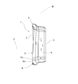
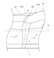
- FIG. 4 is an enlarged view of a part IV in FIG. 3. It is an enlarged view of the V section of FIG. It is a side view of the cutting insert of FIG. It is an enlarged view of the VII part of FIG. It is another side view of the cutting insert of FIG. It is a bottom view of the cutting insert of FIG. It is a perspective view of the cutting insert which concerns on 2nd Embodiment. It is a top view of the cutting insert of FIG. It is a side view of the cutting insert of FIG. It is an enlarged view of the XIII part of FIG.
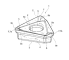
- the cutting insert 1 includes two end surfaces 2 and 3 and a peripheral side surface 4.
- the two end faces 2 and 3 face substantially opposite to each other.
- the peripheral side surface 4 extends between the two end surfaces 2 and 3.
- the cutting insert 1 has a substantially triangular shape when viewed from a direction facing one end surface 2.
- the other end surface 3 also has a substantially triangular shape when viewed from the direction facing the end surface 3. That is, the cutting insert 1 has a substantially triangular plate shape.
- the shape of the cutting insert 1 is 120 ° rotationally symmetric with respect to a reference axis C passing through the two end faces 2 and 3. That is, the cutting insert 1 has a three-fold rotationally symmetric shape with respect to the reference axis C.
- the reference axis C passes through the center of each of the two end faces 2 and 3.
- the cutting insert 1 is formed with a mounting hole 9 extending so as to penetrate these two end faces 2 and 3.
- the central axis of the attachment hole 9 substantially coincides with the reference axis C of the cutting insert 1.
- the reference axis C extends so as to be orthogonal to the first end surface 2.
- the second end surface 3 is a substantially flat surface.
- the second end surface 3 functions as a seating surface when the cutting insert 1 is mounted on the cutting tool 20.
- the first end face 2 and the second end face 3 are arranged in parallel to each other. Therefore, the reference axis C extends so as to be orthogonal to the second end surface 3.
- one end surface 2 of the two end surfaces is referred to as an “upper surface”, and the other end surface 3 is referred to as a “lower surface”.
- the terms “above” and “below” are not intended to limit the present invention and are not intended to be construed in a limited manner based on these terms.
- the cutting insert 1 has a substantially triangular plate shape that is 120 ° rotationally symmetric. Therefore, three corner portions 7 are arranged on the upper surface 2.
- the corner portion 7 located in the lower left is referred to as a first corner portion 7 a
- the corner portion 7 located in the lower right is referred to as a second corner. This is referred to as part 7b.
- an obtuse angle corner exists between the first corner portion 7a and the second corner portion 7b.
- the obtuse angle corner is ignored here, and the upper surface 2 is described as a substantially triangular shape.
- Such obtuse corners may not be present on the upper surface 2.
- the upper surface 2 may have a complicated contour shape in which more corners exist.
- the radius of curvature of the corner portion 7 of the cutting insert 1 is about 0.8 mm.
- a cutting edge 5 is formed at a part of an intersecting ridge line portion between the upper surface 2 and the peripheral side surface 4.
- the cutting edge 5 is formed along the intersecting ridge line portion between the upper surface 2 and the peripheral side surface 4.
- a part of the upper surface 2 functions as a rake face
- a part of the peripheral side surface 4 functions as a flank face
- a cross ridge line portion between the rake face and the flank face functions as a cutting edge 5.
- the cutting edge 5 includes at least two parts 5a and 5b. Two portions 5 a and 5 b of the cutting edge 5 are formed between the adjacent corner portions 7 and 7.
- the portion 5a is referred to as a main cutting edge 5a
- the portion 5b is referred to as a sub cutting edge 5b.
- the main cutting edge 5a and the sub cutting edge 5b are connected by a connecting portion 6.
- the cutting edge 5 includes a main cutting edge 5a, a connecting portion 6, and a sub cutting edge 5b in this order from the first corner portion 7a side to the second corner portion 7b side.
- the cutting insert 1 Since the shape of the cutting insert 1 is 120 ° rotationally symmetric, the cutting insert 1 is formed with three cutting edges 5. Moreover, the main cutting edge 5a and the subcutting edge 5b are formed so that each corner part 7 may be pinched
- the cutting insert 1 has a main cutting edge 5 a and a sub-cutting edge 5 b at an inner angle of about 89 ° with the corner portion 7 interposed therebetween when viewed from the direction facing the upper surface 2. Crossed.
- the cutting insert 1 having such a shape is suitable for right-angle shoulder machining.
- the sub cutting edge 5b can function as a front cutting edge.
- the auxiliary cutting edge 5b may be formed so as to include a finishing edge (wiper edge).
- the main cutting edge 5a is gently curved so as to protrude outward as viewed from the direction facing the upper surface 2. Thereby, the rotation locus of the main cutting edge 5a when the cutting insert 1 is mounted on the cutting tool becomes close to an accurate cylindrical shape.
- the cutting insert 1 has three cutting edges 5. For this reason, even if one cutting edge 5 is used and it reaches the end of its life due to wear or the like, it is possible to continue using the cutting insert 1 by replacing the position with the other cutting edge 5.
- Each cutting edge 5 has the same function. Therefore, in order to simplify the description, only one cutting edge 5 will be described below, and description of the other two cutting edges 5 will be omitted. In addition, for the upper surface 2 and the like, only the part around the one cutting edge 5 will be described, and the explanation about the part around the other cutting edge 5 will be omitted.
- the diameter of the inscribed circle of the substantially triangular upper surface 2 is about 14 mm.
- the length of one side of the upper surface 2 is about 16 mm.
- the thickness of the cutting insert 1 is about 6 mm.
- Each dimension of the cutting insert 1 is adjusted timely according to the shape of the workpiece, cutting conditions, and the like.
- the cutting insert 1 has a cutting edge 5 formed only at a part of the intersecting ridge line portion between the upper surface 2 and the peripheral side surface 4.
- the cutting edge 5 may be formed in the whole area
- the peripheral side surface 4 intersects with the lower surface 3 at an obtuse angle at an internal angle.
- the cutting insert 1 is a so-called positive type as a whole.
- the peripheral side surface 4 has a portion that intersects the upper surface 2 at an acute angle and a portion that intersects an obtuse angle.
- the portion of the peripheral side surface 4 connected to the secondary cutting edge 5b intersects the upper surface 2 at an acute angle
- the portion of the peripheral side surface 4 connected to the main cutting edge 5a intersects the upper surface 2 at an obtuse angle. That is, a portion of the peripheral side surface 4 that is connected to the main cutting edge 5a is formed so that the clearance angle is negative.
- FIG. 5 when the cutting insert 1 is viewed from the direction facing the end surface 2, a part of the peripheral side surface 4 connected to the main cutting edge 5a can be seen.
- a clearance angle of a portion of the peripheral side surface 4 connected to the main cutting edge 5a is approximately ⁇ 3 °, which is substantially constant.
- a virtual intermediate plane M is defined between the upper surface 2 and the lower surface 3.
- the intermediate plane M is preferably defined at the center between the upper surface 2 and the lower surface 3 in parallel with the lower surface 3.
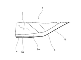
- the main cutting edge 5 a is inclined with respect to the lower surface 3 and the intermediate plane M.
- the main cutting edge 5a has a first inclined portion 5a1.
- the first inclined portion 5a1 is inclined so as to approach the intermediate plane M from the first corner portion 7a side toward the second corner portion 7b side.
- first inclination angle formed by the main cutting edge 5 a with respect to the lower surface 3 is referred to as “first inclination angle A”.
- the first inclination angle A of the cutting insert 1 is about 3 °.
- the connecting portion 6 smoothly connects the main cutting edge 5a and the auxiliary cutting edge 5b.
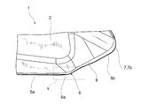
- the connecting portion 6 has a second inclined portion 6 a that is inclined with respect to the lower surface 3 and the intermediate plane M.
- the connection part 6 has the 2nd inclination part 6a which spaces apart from the intermediate plane M as it goes to the sub cutting edge 5b side from the main cutting edge 5a side.
- the inclination angle formed by the second inclined portion 6 a with respect to the lower surface 3 is referred to as “second inclination angle B”.
- the second inclination angle B of the cutting insert 1 is about 30 °.
- the connecting portion 6 has a linear portion 6b on the first inclined portion 5a1 side with respect to the second inclined portion 6a.
- the straight portion 6 b extends with a dimension L substantially parallel to the lower surface 3 and the intermediate plane M.
- the dimension L is a dimension in a direction parallel to the direction in which the lower surface 3 extends, and can be referred to as the length of the linear portion 6b.
- the length L of the linear portion 6b of the cutting insert 1 is about 0.5 mm.
- the upper surface 2 has a land 8.
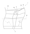
- the land 8 has a band shape and extends along the cutting edge 5 and the connecting portion 6. As shown in FIGS. 4 and 5, the land 8 includes a width-enlarging portion 8 a that increases in width as it goes from the main cutting edge 5 a side to the sub-cutting edge 5 b side in the portion along the connection portion 6.
- the upper surface 2 is closer to the intermediate plane M as it is separated from the intersecting ridge line portion (the cutting blade 5 or the connecting portion 6) between the upper surface 2 and the peripheral side surface 4 in the cutting plane orthogonal to the main cutting edge 5a. It has an inclined part. That is, at least a part of the upper surface 2 has a positive rake angle.
- the rake angle of the land 8 portion is referred to as “the inclination angle of the land 8”. That is, the inclination angle of the land 8 is also called a rake angle.
- the reference (0 °) of the angle of the cutting insert 1 alone for the rake angle and the inclination angle of the land 8 can be a reference line parallel to the lower surface 3.
- the rake angle of the cutting insert 1 and the inclination angle of the land 8 are substantially constant over the entire circumference of the cutting edge 5 and the connection portion 6.
- the rake angle and the inclination angle of the land 8 may be provided so as to change along the cutting edge 5 or the connecting portion 6.
- the rake angle in the vicinity of the main cutting edge 5a of the connecting portion 6 and the inclination angle of the land 8 may be smaller than the rake angle in the vicinity of the first corner portion 7a of the main cutting edge 5a.
- the material of the cutting insert 1 is a cemented carbide, cermet, ceramics and cubic boron nitride, a material in which the surface of these hard materials is coated, or diamond at least near the cutting edge 5.
- the material of parts other than the cutting edge 5 vicinity is also the same hard material.
- the cutting insert 1 having the above-described configuration is attached to the tool body 21 of the cutting tool 20 as shown in FIG.
- the cutting tool 20 is a rotary cutting tool. More specifically, the cutting tool 20 is a luffing cutter capable of performing right-angle shoulder machining.
- the cutting insert 1 is detachably attached to the tool body 21 using a clamp member that is a mechanical attachment means.
- the cutting tool 20 uses a clamping screw 24 as a clamp member.
- the cutting tool 20 includes a tool body 21 in which a plurality of (here, 20 in 4 rows and 5 stages) chip seats 22 are formed.
- One cutting insert 1 can be detachably mounted on each chip seat 22.
- the present invention does not exclude a cutting tool including a tool body provided with only one chip seat.
- the tool body 21 is formed in a substantially cylindrical shape as a whole.
- the tool body 21 is configured to rotate around the central axis AX.
- the center axis AX is determined so as to penetrate the tool body 21 from the front end 21a to the rear end 21b side.
- the direction in which the tip seat 22 advances as the tool body 21 rotates is referred to as “forward in the rotational direction”.
- the four tip seats 22 are formed at equal intervals on the tip 21a of the tool body 21.
- a chip pocket 23 is formed in front of each chip seat 22 in the rotational direction.
- Each chip pocket 23 extends spirally from the front end 21a toward the rear end 21b.
- five chip seats 22 are arranged stepwise.
- the plurality of cutting inserts 1 used in the cutting tool 20 all have the same configuration and the same shape.
- the shape of the plurality of chip seats 22 may be slightly different depending on the position on the tool body 21.
- the shape of the tip seat 22 arranged closest to the tip 21 a is different from the shape of the tip seat 22 arranged closer to the rear end 21 b than the tip seat 22.
- the tip seat 22 arranged on the most distal end 21a side is formed such that the auxiliary cutting edge 5b of the cutting insert 1 functions as a front edge.
- the auxiliary cutting edge 5b does not function as a front edge.
- each chip seat 22 has a bottom surface and a wall surface, and is open toward the outer peripheral side of the tool body 21. Further, the tip seat 22 arranged on the most distal end 21 a side is also opened toward the distal end 21 a side of the tool body 21.
- the surface with which the lower surface 3 of the cutting insert 1 contacts is referred to as the bottom surface of the chip seat 22. Further, the surface with which the peripheral side surface 4 of the cutting insert 1 contacts is referred to as the wall surface of the tip seat 22. Therefore, the bottom surface faces forward in the rotational direction.
- the cutting insert 1 is disposed on the chip seat 22 so that a pair of main cutting edges 5a and sub cutting edges 5b sandwiching one corner portion 7 can be used, and is fixed by a fastening screw.
- the bottom surface of the chip seat 22 is formed with a screw hole into which the fastening screw 24 is screwed.
- the cutting insert 1 has a first inclined portion 5 a 1 whose main cutting edge 5 a is inclined with respect to the lower surface 3. For this reason, the main cutting edge 5a is suitable for reducing cutting resistance or improving chip dischargeability. Moreover, the cutting insert 1 has the linear part 6b in the connection part 6 between the main cutting edge 5a and the subcutting edge 5b. As shown in FIG. 7, the inclination angle (0 °) formed by the linear portion 6b with respect to the lower surface 3 is smaller than the inclination angle A (3 °) formed by the first inclined portion 5a1 with respect to the lower surface 3. The connection part 6 has the linear part 6b on the main cutting edge 5a side.
- a linear portion 6b having a sufficient length is required.
- the length L of the linear portion 6b is preferably in the range of 0.2 mm or more and 5 mm or less. If the length L of the linear portion 6b is less than 0.2 mm, chips cannot be discharged smoothly, and defects and chipping are likely to occur from the connection portion 6.
- the connection part 6 is a part which connects the main cutting edge 5a and the sub-cutting edge 5b, if the length L of the linear part 6b exceeds 5 mm, the cutting insert 1 will become large too much. As described above, the cutting insert 1 has the linear portion 6 b parallel to the lower surface 3. For this reason, as shown in FIG.
- the length L of the linear part 6b corresponds to the length in the direction parallel to the direction in which the lower surface 3 extends.
- the length in a direction parallel to the direction in which the lower surface 3 extends in front view may be determined as the length L of the linear portion 6b.
- the inclination angle B shown in FIG. 6 is 0 ° or a negative angle
- the second inclined portion 6a rises sharply with respect to the first inclined portion 5a1 of the main cutting edge 5a, so that chip discharge is easily inhibited. If the discharge of chips is hindered, chips are likely to accumulate around the connection portion 6, and defects and chipping are likely to occur from the connection portion 6.
- the inclination angle B is larger than 0 ° and not more than 40 °. This prevents the second inclined portion 6a of the connecting portion 6 from rising sharply with respect to the inclined portion 5a1 of the main cutting edge 5a.
- the connecting portion 6 may be provided with a plurality of inclined portions in stages.
- the inclined portion closest to the main cutting edge 5a may be the second inclined portion 6a, and the aforementioned inclination angle B may be used.
- the inclination angles of all the inclined portions are larger than 0 ° and not more than 40 °.
- the cutting insert 1 As described above, in the cutting insert 1, a portion of the peripheral side surface 4 that is connected to the main cutting edge 5a is formed so that the clearance angle is negative. Therefore, the strength of the main cutting edge 5a is high, and chipping and chipping hardly occur.
- the cutting insert 1 is attached to the cutting tool 20 so that the clearance angle of the main cutting edge 5a is positive.
- the lands 8 When the upper surface 2 has the lands 8, the lands 8 preferably include a width-enlarging portion 8a whose width increases from the main cutting edge 5a side toward the sub-cutting edge 5b side. By increasing the width of the land 8, it is possible to prevent the connection portion 6 from being damaged or chipped.
- the width of the land 8 is preferably changed so as to be smoothly connected to the auxiliary cutting edge 5b.
- the width of the land 8 of the cutting insert 1 gradually changes in the portion connected to the connection portion 6.
- the width of the land 8 is about 0.1 mm at a portion connected to the main cutting edge 5a, and is about 0.3 mm at a portion connected to the sub cutting edge 5b.
- the land 8 may further include a width-reduced portion (not shown) closer to the auxiliary cutting edge 5b than the widened portion 8a.
- the width reduction portion is a portion where the width decreases as it goes from the main cutting edge 5a side to the sub cutting edge 5b side.
- the land 8 includes both the width-enlarged portion 8a and the width-reduced portion, so that the width of the land 8 in the connecting portion 6 is increased without being restricted by the width of the land 8 in the main cutting edge 5a and the sub-cutting edge 5b. be able to. As a result, it is possible to prevent the chipping and chipping at the connection portion 6 where the chipping and chipping are most likely to occur.
- the width of the land 8 of the connection part 6 is the same as the width of the land 8 of the main cutting edge 5a in the part related to cutting. Moreover, it is preferable that the width expansion part 8a starts to expand in width from the linear part 6b or the arcuate part of the connecting part 6.
- the rake angle in the vicinity of the main cutting edge 5a of the connecting portion 6 or the inclination angle of the land 8 is preferably smaller than the rake angle in the vicinity of the first corner portion 7a of the main cutting edge 5a. In other words, it is preferable that the rake angle at the connecting portion 6 or the inclination angle of the land 8 is smaller than the rake angle at the main cutting edge 5a. More preferably, the rake angle in the vicinity of the main cutting edge 5a of the connection portion 6 or the inclination angle of the land 8 is 0 °.
- the cutting edge 5 and the connecting portion 6 may have honing (not shown). It is preferable that the size of the honing in the connection part 6 is larger than the size of the honing in the main cutting edge 5a. By increasing the size of the honing in the connection portion 6, the strength of the connection portion 6 can be increased and the occurrence of chipping or chipping from the connection portion 6 can be prevented. In addition, the dimension of a honing can also be represented by the width of the honing regarding the rake face side.
- the cutting insert 1 is attached to the tool body 21 by a clamp member.
- a clamp member a known technique such as a wedge or a pressing piece can be applied.
- a roughing cutter such as the cutting tool 20 is required to discharge chips efficiently.
- a tightening screw 24 for mounting the cutting insert 1.
- the tightening screw 24 it is possible to easily attach the cutting insert 1 having a lower central surface portion to the cutting edge 5. Further, since there are no obstacles such as wedges or pressing pieces on the rake face side, chips can be discharged efficiently.
- Such a cutting tool can be used for cutting a steel material by being mounted on a machine tool.
- the cutting insert 101 according to the second embodiment will be described with reference to FIGS. 10 to 13.
- the same components as those of the cutting insert 1 according to the first embodiment are denoted by the same reference numerals, and description thereof is omitted.
- the structure of the cutting insert 101 a different part from the cutting insert 1 which concerns on 1st Embodiment is mainly demonstrated.
- the cutting insert 101 includes an upper surface 2 and a lower surface 3 facing substantially opposite to each other, and a peripheral side surface 4 extending therebetween. As shown in FIG. 11, the cutting insert 101 has a substantially triangular shape when viewed from the direction facing the upper surface 2. An attachment hole 9 extending so as to penetrate the upper surface 2 and the lower surface 3 is formed.
- the cutting edge 5 includes at least a main cutting edge 5a and a sub cutting edge 5b.
- the main cutting edge 5 a and the sub cutting edge 5 b are formed between the adjacent corner portions 7 and 7.
- a virtual intermediate plane M is defined between the upper surface 2 and the lower surface 3.
- the main cutting edge 5a is inclined with respect to the lower surface 3 and the intermediate plane M when viewed in parallel with the lower surface 3 from the side surface 4 connected to the main cutting edge 5a.
- the main cutting edge 5a and the sub cutting edge 5b are connected via the connection part 102.
- the cutting edge 5 includes a main cutting edge 5a, a connecting portion 102, and a sub cutting edge 5b in this order from the first corner portion 7a side to the second corner portion 7b side.
- the connecting portion 102 smoothly connects the main cutting edge 5a and the sub cutting edge 5b.
- the connecting portion 102 has a second inclined portion 102 a that is inclined with respect to the lower surface 3 and the intermediate plane M.
- the connection part 102 has the 2nd inclination part 102a spaced apart from the intermediate plane M as it goes to the sub cutting edge 5b side from the main cutting edge 5a side. That is, as shown in FIG. 12, when viewed from the side of the peripheral side surface 4 connected to the main cutting edge 5a in parallel with the lower surface 3, the connecting portion 102 has a second slope that is separated from the lower surface 3 and the intermediate plane M toward the right side. It has a portion 102a.
- an inclination angle formed by the second inclined portion 102 a with respect to the lower surface 3 is referred to as a “second inclination angle B”.
- the second inclination angle B of the cutting insert 101 is about 30 °.
- the connecting portion 102 has an arcuate portion 102b formed in a substantially arcuate shape on the first inclined portion 5a1 side from the second inclined portion 102a.
- the arcuate portion 102b is an arc having a radius of curvature R.
- the curvature radius R is about 70 mm.
- the arc-shaped portion 102b looks almost linear with the naked eye.
- 10 to 13 schematically illustrate the roundness of the arcuate portion 102b with emphasis. Further, in FIGS. 10 to 13, the arcuate portion 102b is drawn so as to be smoothly connected to the second inclined portion 102a.
- arcuate portion 102b may be formed between the arcuate portion 102b and the second inclined portion 102a (not shown).
- the other arcuate part may have any shape.
- the cutting insert 101 having the above configuration can be detachably mounted on the same tool body 21 as the cutting tool 20 in the first embodiment.
- worn since it is the same as that of the cutting tool 20 in 1st Embodiment, description is abbreviate
- the cutting insert 101 has the 1st inclination part 5a1 in which the main cutting edge 5a inclines with respect to the lower surface 3 similarly to the cutting insert 1 in 1st Embodiment.
- the connection portion 102 between the main cutting edge 5a and the sub cutting edge 5b has an arcuate portion 102b having a curvature radius R. Since the connecting portion 102 has the arcuate portion 102b, it is prevented that the connecting portion 102 rises sharply with respect to the first inclined portion 5a1 of the main cutting edge 5a. Thereby, the connection part 102 does not inhibit the discharge
- the arc-shaped portion 102b having a large curvature radius R can obtain the same operations and effects as the linear portion 6b of the cutting insert 1 according to the first embodiment.
- the radius of curvature R of the arcuate portion 102b is preferably in the range of 5 mm or more and 1000 mm or less.
- the curvature radius R is more preferably in the range of 50 mm or more and 1000 mm or less. If the curvature radius R is less than 5 mm, chip discharge may be hindered.
- the radius of curvature R is 50 mm or more, substantially the same operation and effect as the linear portion 6b can be obtained.
- the present invention can be applied to a cutting insert having a nick.
- the main cutting edge was made into linear form, you may be made into the wavy main cutting edge from which an inclination angle fluctuates.
- the present invention is not limited to a luffing cutter capable of cutting right shoulders, but can be applied to a face mill with various cutting edge angles, a disk-shaped side cutter, and the like.
- the present invention can be applied not only to the rolling tool as in the above embodiment, but also to other types of cutting tools such as a turning tool and a drilling tool.
- connection part 6 which concerns on 1st Embodiment mentioned above has the linear part 6b.
- the connecting portion 102 according to the second embodiment has an arcuate portion 102b.
- the present invention is not limited to these embodiments. That is, the connection part according to the present invention may have both a linear part and an arc-shaped part.
- Cutting insert 2 First end face (upper surface) 3 Second end face (lower face) 4 peripheral side surface 5 cutting edge 5a first cutting edge (main cutting edge) 5a1 First inclined portion 5b Second cutting edge (sub cutting edge) 6 connecting portion 6a second inclined portion 6b linear portion 7 corner portion 7a first corner portion 7b second corner portion 8 land 8a widened portion 9 mounting hole 20 cutting tool 101 cutting insert 102 connecting portion 102a second Inclined portion 102b Arc-shaped portion A First angle B Second angle C Reference axis L of cutting insert Straight portion length M Intermediate plane R Radius of curvature of arc-shaped portion
Landscapes
- Engineering & Computer Science (AREA)
- Mechanical Engineering (AREA)
- Milling Processes (AREA)
Abstract
Description
2 第1の端面(上面)
3 第2の端面(下面)
4 周側面
5 切れ刃
5a 第1の切れ刃(主切れ刃)
5a1 第1の傾斜部分
5b 第2の切れ刃(副切れ刃)
6 接続部
6a 第2の傾斜部分
6b 直線状部分
7 コーナ部
7a 第1のコーナ部
7b 第2のコーナ部
8 ランド
8a 幅拡大部分
9 取り付け穴
20 切削工具
101 切削インサート
102 接続部
102a 第2の傾斜部分
102b 円弧状部分
A 第1の角度
B 第2の角度
C 切削インサートの基準軸線
L 直線状部分の長さ
M 中間平面
R 円弧状部分の曲率半径
Claims (13)
- 切削工具に装着される切削インサート(1)であって、
第1のコーナ部(7a)および第2のコーナ部(7b)を有する第1の端面(2)と、
前記第1の端面(2)に対して反対側を向いた第2の端面(3)と、
前記第1の端面(2)と前記第2の端面(3)との間に延在する周側面(4)と、
該第1の端面(2)と該周側面(4)との交差稜線部の少なくとも一部をなす切れ刃(5)と、を備え、
前記切れ刃(5)は、前記第1のコーナ部(7a)と前記第2のコーナ部(7b)の間に、第1の切れ刃(5a)と、該第1の切れ刃(5a)に対して該第1のコーナ部(7a)とは反対側に配置された第2の切れ刃(5b)とを含み、
前記第1の切れ刃(5a)と前記第2の切れ刃(5b)とは接続部(6)を介して互いに接続され、
前記第1の端面(2)と前記第2の端面(3)の間に配置され前記周側面(4)と交差する中間平面(M)を定めるとき、
前記第1の切れ刃(5a)は、前記第1のコーナ部(7a)から離間するにつれ該中間平面(M)に近づく第1の傾斜部分(5a1)を有し、
前記接続部(6)は、前記第1の切れ刃(5a)から離間するにつれ前記中間平面(M)から離間する第2の傾斜部分(6a)と、該第2の傾斜部分(6a)と前記第1の傾斜部分(5a1)の間において側面視で直線状に延伸する直線状部分(6b)とを有し、
側面視で、前記直線状部分(6b)は、前記第2の端面(3)に対する傾斜角度が前記第1の傾斜部分(5a1)の傾斜角度(A)よりも小さい切削インサート。 - 側面視で、前記直線状部分(6b)は、前記第2の端面(3)と略平行である請求項1に記載の切削インサート。
- 側面視で、前記第2の端面(3)が延びる方向と平行な方向における前記直線状部分(6b)の長さ(L)は、0.2mm以上、かつ5mm以下の範囲にある請求項1または2に記載の切削インサート。
- 切削工具に装着される切削インサート(101)であって、
第1のコーナ部(7a)および第2のコーナ部(7b)を有する第1の端面(2)と、
前記第1の端面(2)に対して反対側を向いた第2の端面(3)と、
前記第1の端面(2)と前記第2の端面(3)との間に延在する周側面(4)と、
前記第1の端面(2)と該周側面(4)との交差稜線部の少なくとも一部をなす切れ刃(5)と、を備え、
前記切れ刃(5)は、前記第1のコーナ部(7a)と前記第2のコーナ部(7b)の間に、第1の切れ刃(5a)と、該第1の切れ刃(5a)に対して該第1のコーナ部(7a)とは反対側に配置された第2の切れ刃(5b)とを含み、
前記第1の切れ刃(5a)と前記第2の切れ刃(5b)とは接続部(102)を介して互いに接続され、
前記第1の端面(2)と前記第2の端面(3)の間に配置され前記周側面(4)と交差する中間平面(M)を定めるとき、
前記第1の切れ刃(5a)は、前記第1のコーナ部(7a)から離間するにつれ該中間平面(M)に近づく第1の傾斜部分(5a1)を有し、
前記接続部(102)は、前記第1の切れ刃(5a)から離間するにつれ前記中間平面(M)から離間する第2の傾斜部分(102a)と、該第2の傾斜部分(102a)と前記第1の傾斜部分(5a1)の間において側面視で略円弧状に湾曲するように延伸する円弧状部分(102b)とを有し、
側面視で、該円弧状部分(102b)を円弧で近似したときの曲率半径(R)は、5mm以上、かつ1000mm以下の範囲にある切削インサート。 - 側面視で、前記第2の傾斜部分(6a、102a)の前記第2の端面(3)に対する傾斜角度(B)は、0°よりも大きく、かつ40°以下の範囲にある請求項1から4のいずれか一項に記載の切削インサート。
- 前記第1の端面(2)は、前記接続部(6、102)に沿って延伸する帯状のランド(8)を有し、
前記ランド(8)は、前記第1の切れ刃(5a)側から前記第2の切れ刃(5b)側に向かうにつれ幅が拡大する幅拡大部分(8a)を含む請求項1から5のいずれか一項に記載の切削インサート。 - 前記ランド(8)は、前記幅拡大部分(8a)よりも前記第2の切れ刃(5b)側に、前記第1の切れ刃(5a)側から前記第2の切れ刃(5b)側に向かうにつれ幅が縮小する幅縮小部分をさらに含む請求項6に記載の切削インサート。
- 前記第1の端面(2)に対向する方向から見て前記第1の切れ刃(5a)と直交する切断面において、前記第2の端面(3)と平行な直線を角度の基準とし、前記第1の端面(2)と前記周側面(4)との交差稜線部から離間するにつれ前記中間平面(M)に近づくように前記第1の端面(2)が傾斜する場合を正のすくい角と定めるとき、前記接続部(6、102)の前記第1の切れ刃(5a)近傍でのすくい角は、前記第1の切れ刃(5a)の前記第1のコーナ部(7a)近傍でのすくい角よりも小さい請求項1から5のいずれか一項に記載の切削インサート。
- 前記第1の端面(2)に対向する方向から見て前記第1の切れ刃(5a)と直交する切断面において、前記第2の端面(3)と平行な直線を角度の基準とし、前記ランド(8)の傾斜角度をすくい角とするとき、前記接続部(6、102)の前記第1の切れ刃(5a)近傍でのすくい角は、前記第1の切れ刃(5a)の前記第1のコーナ部(7a)近傍でのすくい角よりも小さい請求項6または7に記載の切削インサート。
- 前記接続部(6、102)の前記第1の切れ刃(5a)近傍での前記すくい角は、0°とされる請求項8または9に記載の切削インサート。
- 前記切れ刃(5)および前記接続部(6、102)はホーニングを有し、
前記接続部(6、102)におけるホーニングの寸法は、前記第1の切れ刃(5a)におけるホーニングの寸法よりも大きい請求項1から10のいずれか一項に記載の切削インサート。 - 請求項1から11のいずれか一項に記載の切削インサート(1、101)を備える切削工具。
- 複数の前記切削インサート(1、101)を備え、
少なくとも2つの前記切削インサート(1)は、工具回転軸線方向の配置位置が互いにずれている請求項12に記載の切削工具。
Priority Applications (1)
| Application Number | Priority Date | Filing Date | Title |
|---|---|---|---|
| JP2017514724A JP6361948B2 (ja) | 2015-10-19 | 2016-09-28 | 切削インサートおよび切削工具 |
Applications Claiming Priority (2)
| Application Number | Priority Date | Filing Date | Title |
|---|---|---|---|
| JP2015-205226 | 2015-10-19 | ||
| JP2015205226 | 2015-10-19 |
Publications (1)
| Publication Number | Publication Date |
|---|---|
| WO2017068922A1 true WO2017068922A1 (ja) | 2017-04-27 |
Family
ID=58556920
Family Applications (1)
| Application Number | Title | Priority Date | Filing Date |
|---|---|---|---|
| PCT/JP2016/078626 Ceased WO2017068922A1 (ja) | 2015-10-19 | 2016-09-28 | 切削インサートおよび切削工具 |
Country Status (2)
| Country | Link |
|---|---|
| JP (1) | JP6361948B2 (ja) |
| WO (1) | WO2017068922A1 (ja) |
Cited By (6)
| Publication number | Priority date | Publication date | Assignee | Title |
|---|---|---|---|---|
| CN109222136A (zh) * | 2018-10-23 | 2019-01-18 | 武汉轻工大学 | 一种手摇式荸荠削皮机 |
| KR20190081058A (ko) * | 2017-12-29 | 2019-07-09 | 한국야금 주식회사 | 절삭 인서트 및 이를 장착한 절삭 공구 |
| US20200130072A1 (en) * | 2018-10-31 | 2020-04-30 | Kyocera Corporation | Cutting insert, cutting tool, and method for manufacturing machined product |
| CN112105475A (zh) * | 2018-05-07 | 2020-12-18 | 京瓷株式会社 | 切削刀片、切削刀具以及切削加工物的制造方法 |
| EP3808483A1 (en) | 2019-10-18 | 2021-04-21 | Tungaloy Corporation | Cutting insert and milling tool |
| US11453073B2 (en) | 2019-10-18 | 2022-09-27 | Tungaloy Corporation | Cutting insert and milling tool |
Citations (7)
| Publication number | Priority date | Publication date | Assignee | Title |
|---|---|---|---|---|
| JPH07246505A (ja) * | 1994-03-09 | 1995-09-26 | Mitsubishi Materials Corp | スローアウェイチップ及び切削工具 |
| JPH08118135A (ja) * | 1994-10-19 | 1996-05-14 | Toshiba Tungaloy Co Ltd | 回転切削工具用のスローアウェイチップ |
| US20070071559A1 (en) * | 2005-09-28 | 2007-03-29 | Seco Tools Ab | Milling insert and a milling tool |
| US20080232912A1 (en) * | 2007-03-21 | 2008-09-25 | Taegutec India P Ltd. | Cutting Insert for a Milling Cutter |
| JP2014524365A (ja) * | 2011-08-26 | 2014-09-22 | セラティチット オーストリア ゲゼルシャフト ミット ベシュレンクテル ハフツング | フライス用両面切削インサート |
| WO2015080168A1 (ja) * | 2013-11-27 | 2015-06-04 | 株式会社タンガロイ | 切削インサート及び刃先交換式切削工具 |
| JP2015521958A (ja) * | 2012-07-06 | 2015-08-03 | イスカル リミテッド | 回転切削工具およびその可逆性切削インサート |
-
2016
- 2016-09-28 WO PCT/JP2016/078626 patent/WO2017068922A1/ja not_active Ceased
- 2016-09-28 JP JP2017514724A patent/JP6361948B2/ja active Active
Patent Citations (7)
| Publication number | Priority date | Publication date | Assignee | Title |
|---|---|---|---|---|
| JPH07246505A (ja) * | 1994-03-09 | 1995-09-26 | Mitsubishi Materials Corp | スローアウェイチップ及び切削工具 |
| JPH08118135A (ja) * | 1994-10-19 | 1996-05-14 | Toshiba Tungaloy Co Ltd | 回転切削工具用のスローアウェイチップ |
| US20070071559A1 (en) * | 2005-09-28 | 2007-03-29 | Seco Tools Ab | Milling insert and a milling tool |
| US20080232912A1 (en) * | 2007-03-21 | 2008-09-25 | Taegutec India P Ltd. | Cutting Insert for a Milling Cutter |
| JP2014524365A (ja) * | 2011-08-26 | 2014-09-22 | セラティチット オーストリア ゲゼルシャフト ミット ベシュレンクテル ハフツング | フライス用両面切削インサート |
| JP2015521958A (ja) * | 2012-07-06 | 2015-08-03 | イスカル リミテッド | 回転切削工具およびその可逆性切削インサート |
| WO2015080168A1 (ja) * | 2013-11-27 | 2015-06-04 | 株式会社タンガロイ | 切削インサート及び刃先交換式切削工具 |
Cited By (9)
| Publication number | Priority date | Publication date | Assignee | Title |
|---|---|---|---|---|
| KR20190081058A (ko) * | 2017-12-29 | 2019-07-09 | 한국야금 주식회사 | 절삭 인서트 및 이를 장착한 절삭 공구 |
| KR102011329B1 (ko) | 2017-12-29 | 2019-08-14 | 한국야금 주식회사 | 절삭 인서트 및 이를 장착한 절삭 공구 |
| CN112105475A (zh) * | 2018-05-07 | 2020-12-18 | 京瓷株式会社 | 切削刀片、切削刀具以及切削加工物的制造方法 |
| CN112105475B (zh) * | 2018-05-07 | 2023-05-05 | 京瓷株式会社 | 切削刀片、切削刀具以及切削加工物的制造方法 |
| CN109222136A (zh) * | 2018-10-23 | 2019-01-18 | 武汉轻工大学 | 一种手摇式荸荠削皮机 |
| CN109222136B (zh) * | 2018-10-23 | 2024-03-22 | 武汉轻工大学 | 一种手摇式荸荠削皮机 |
| US20200130072A1 (en) * | 2018-10-31 | 2020-04-30 | Kyocera Corporation | Cutting insert, cutting tool, and method for manufacturing machined product |
| EP3808483A1 (en) | 2019-10-18 | 2021-04-21 | Tungaloy Corporation | Cutting insert and milling tool |
| US11453073B2 (en) | 2019-10-18 | 2022-09-27 | Tungaloy Corporation | Cutting insert and milling tool |
Also Published As
| Publication number | Publication date |
|---|---|
| JPWO2017068922A1 (ja) | 2017-10-19 |
| JP6361948B2 (ja) | 2018-07-25 |
Similar Documents
| Publication | Publication Date | Title |
|---|---|---|
| EP2214857B1 (en) | Tangential cutting insert | |
| KR102548552B1 (ko) | 선삭 인서트 | |
| JP5988186B1 (ja) | 切削インサート及び刃先交換式回転切削工具 | |
| CN102413976B (zh) | 切削用刀片和端面铣刀 | |
| KR102624246B1 (ko) | 선삭 인서트 및 방법 | |
| JP6361948B2 (ja) | 切削インサートおよび切削工具 | |
| JP5999586B2 (ja) | 切削インサート及び刃先交換式回転切削工具 | |
| JP4973259B2 (ja) | 切削インサートおよびインサート着脱式転削工具 | |
| CN102413977B (zh) | 切削用刀片和刃尖可替换式端面铣刀 | |
| CN105792968B (zh) | 钻头用刀片及可转位刀片式钻头 | |
| TWI776939B (zh) | 具有彎曲副切削刃及角切削刃的方形切削刀塊、及旋轉切削刀具 | |
| US20180036811A1 (en) | Cutting tool and indexable rotary cutting tool | |
| WO2017122715A1 (ja) | 切削インサートおよび刃先交換式切削工具 | |
| WO2014148515A1 (ja) | 切削インサート及び刃先交換式切削工具 | |
| WO2016147493A1 (ja) | 切削インサート、切削インサート群および刃先交換式切削工具 | |
| US6619891B2 (en) | Milling tool having cutting members with different clearance angles | |
| JP6011831B2 (ja) | 刃先交換式回転切削工具 | |
| JP2017080864A (ja) | 刃先交換式リーマおよびリーマ用インサート | |
| JP2007021622A (ja) | チップおよび転削工具 | |
| JP2022081568A (ja) | 切削インサートおよび刃先交換式ボールエンドミル | |
| CN113396026B (zh) | 用于金属切削的车削刀片 | |
| JP2016187836A (ja) | 切削インサート及び刃先交換式切削工具 | |
| JP6318558B2 (ja) | 切削インサートおよび刃先交換式穴加工工具 | |
| JP4500748B2 (ja) | スローアウェイ式工具 | |
| WO2013015404A1 (ja) | 刃先交換式回転切削工具およびこれに用いる切削インサート |
Legal Events
| Date | Code | Title | Description |
|---|---|---|---|
| ENP | Entry into the national phase |
Ref document number: 2017514724 Country of ref document: JP Kind code of ref document: A |
|
| 121 | Ep: the epo has been informed by wipo that ep was designated in this application |
Ref document number: 16857240 Country of ref document: EP Kind code of ref document: A1 |
|
| NENP | Non-entry into the national phase |
Ref country code: DE |
|
| 122 | Ep: pct application non-entry in european phase |
Ref document number: 16857240 Country of ref document: EP Kind code of ref document: A1 |
|
| REG | Reference to national code |
Ref country code: BR Ref legal event code: B01E Ref document number: 112018012275 Country of ref document: BR Free format text: ESCLARECER, EM ATE 60 (SESSENTA) DIAS, A DIVERGENCIA ENTRE O PCT QUE CONSTA NO FORMULARIO DE ENTRADA NA FASE NACIONAL PCT/JP2016/078526 DE 28/09/2019 E O CONTEUDO APRESENTADO NA PETICAO INICIAL NO 870180051581 DE 15/06/2018 |
|
| ENP | Entry into the national phase |
Ref document number: 112018012275 Country of ref document: BR Kind code of ref document: A2 Effective date: 20180615 |