WO2017068767A1 - Dispositif et procédé de soudage par point avec friction et agitation - Google Patents
Dispositif et procédé de soudage par point avec friction et agitation Download PDFInfo
- Publication number
- WO2017068767A1 WO2017068767A1 PCT/JP2016/004589 JP2016004589W WO2017068767A1 WO 2017068767 A1 WO2017068767 A1 WO 2017068767A1 JP 2016004589 W JP2016004589 W JP 2016004589W WO 2017068767 A1 WO2017068767 A1 WO 2017068767A1
- Authority
- WO
- WIPO (PCT)
- Prior art keywords
- tool
- joining
- breakage
- friction stir
- plate
- Prior art date
Links
Images


Classifications
-
- B—PERFORMING OPERATIONS; TRANSPORTING
- B23—MACHINE TOOLS; METAL-WORKING NOT OTHERWISE PROVIDED FOR
- B23K—SOLDERING OR UNSOLDERING; WELDING; CLADDING OR PLATING BY SOLDERING OR WELDING; CUTTING BY APPLYING HEAT LOCALLY, e.g. FLAME CUTTING; WORKING BY LASER BEAM
- B23K20/00—Non-electric welding by applying impact or other pressure, with or without the application of heat, e.g. cladding or plating
- B23K20/12—Non-electric welding by applying impact or other pressure, with or without the application of heat, e.g. cladding or plating the heat being generated by friction; Friction welding
- B23K20/122—Non-electric welding by applying impact or other pressure, with or without the application of heat, e.g. cladding or plating the heat being generated by friction; Friction welding using a non-consumable tool, e.g. friction stir welding
- B23K20/127—Non-electric welding by applying impact or other pressure, with or without the application of heat, e.g. cladding or plating the heat being generated by friction; Friction welding using a non-consumable tool, e.g. friction stir welding friction stir welding involving a mechanical connection
-
- B—PERFORMING OPERATIONS; TRANSPORTING
- B23—MACHINE TOOLS; METAL-WORKING NOT OTHERWISE PROVIDED FOR
- B23K—SOLDERING OR UNSOLDERING; WELDING; CLADDING OR PLATING BY SOLDERING OR WELDING; CUTTING BY APPLYING HEAT LOCALLY, e.g. FLAME CUTTING; WORKING BY LASER BEAM
- B23K20/00—Non-electric welding by applying impact or other pressure, with or without the application of heat, e.g. cladding or plating
- B23K20/12—Non-electric welding by applying impact or other pressure, with or without the application of heat, e.g. cladding or plating the heat being generated by friction; Friction welding
- B23K20/122—Non-electric welding by applying impact or other pressure, with or without the application of heat, e.g. cladding or plating the heat being generated by friction; Friction welding using a non-consumable tool, e.g. friction stir welding
- B23K20/123—Controlling or monitoring the welding process
-
- B—PERFORMING OPERATIONS; TRANSPORTING
- B23—MACHINE TOOLS; METAL-WORKING NOT OTHERWISE PROVIDED FOR
- B23K—SOLDERING OR UNSOLDERING; WELDING; CLADDING OR PLATING BY SOLDERING OR WELDING; CUTTING BY APPLYING HEAT LOCALLY, e.g. FLAME CUTTING; WORKING BY LASER BEAM
- B23K20/00—Non-electric welding by applying impact or other pressure, with or without the application of heat, e.g. cladding or plating
- B23K20/12—Non-electric welding by applying impact or other pressure, with or without the application of heat, e.g. cladding or plating the heat being generated by friction; Friction welding
- B23K20/122—Non-electric welding by applying impact or other pressure, with or without the application of heat, e.g. cladding or plating the heat being generated by friction; Friction welding using a non-consumable tool, e.g. friction stir welding
- B23K20/1245—Non-electric welding by applying impact or other pressure, with or without the application of heat, e.g. cladding or plating the heat being generated by friction; Friction welding using a non-consumable tool, e.g. friction stir welding characterised by the apparatus
-
- B—PERFORMING OPERATIONS; TRANSPORTING
- B23—MACHINE TOOLS; METAL-WORKING NOT OTHERWISE PROVIDED FOR
- B23K—SOLDERING OR UNSOLDERING; WELDING; CLADDING OR PLATING BY SOLDERING OR WELDING; CUTTING BY APPLYING HEAT LOCALLY, e.g. FLAME CUTTING; WORKING BY LASER BEAM
- B23K20/00—Non-electric welding by applying impact or other pressure, with or without the application of heat, e.g. cladding or plating
- B23K20/26—Auxiliary equipment
Definitions
- the present invention relates to a friction stir spot welding apparatus and a friction stir spot welding method.
- a friction stir spot joining method (Friction Spot Joining) is known as a method for joining a pair of plate materials to each other.
- Friction Spot Joining When joining a pair of board
- the tool may break when the tool is pulled out after a pair of plate members are joined at the friction stir spot at one joining position. If the breakage of the tool that occurs after the friction stir spot welding of a pair of plate materials at the preceding joining position cannot be detected before the friction stir spot welding at the next joining position, the broken tool causes a joint failure of the pair of plate materials. There is a problem that can cause damage. In addition, there is a problem that the friction stir spot welding device can be damaged by tool blurring caused by breakage of the tool or a sudden increase in torque.
- the present invention provides the following joining of the tool breakage that occurs after a pair of plate materials are friction stir spot welded at the preceding joining position when a pair of plate materials are continuously joined at a plurality of joining positions.
- a friction stir spot welding apparatus is a friction stir point that continuously joins a plurality of first plate members and second plate members at a plurality of joint positions.
- a joining device a tool capable of contacting or separating from a surface of the second plate member opposite to the first plate member, a drive unit for rotating the tool around its axis, the tool, and the second plate
- a position adjusting unit that adjusts a relative position between the plate member, a control unit that controls the driving unit and the position adjusting unit, and one of the plurality of bonding positions, the tool is the second A breakage detection unit that detects breakage of the tool by controlling the control unit so as to be disposed at a position in contact with the plate member or a predetermined pushing position;
- the breakage detection unit controls the control unit so that the breakage detection unit controls the breakage of the tool so that the tool is brought into contact with the second plate member or disposed at the predetermined push-in position at one joining position. Therefore, it is possible to detect breakage occurring in the tool before the friction stir spot welding is performed at one joining position. Therefore, in the case where the first plate member and the second plate member are continuously joined at the friction stir spot at the plurality of joining positions, the breakage generated in the tool after the friction stir spot joining at the preceding joining position is prevented at the next joining position. Detectable before friction stir spot welding.
- the breakage detecting unit is configured to apply pressure by which the tool pressurizes the second plate member after the tip of the tool and the second plate member come into contact until the tip of the tool is disposed at the predetermined pushing position.
- the breakage of the tool may be detected based on the amount of change in pressure.
- the breakage detection unit detects the amount of change in the applied pressure and detects the breakage of the tool, so that the breakage of the tool can be detected well even if the pressurization value of the tool is different from the actual value. Therefore, for example, it is possible to improve the detection accuracy of the tool breakage by the breakage detection unit as compared with the case of detecting the tool breakage by capturing the fixed value of the applied pressure.
- the load detection unit further includes a load detection unit that receives the pressure from the surface of the first plate opposite to the second plate, and the breakage detection unit outputs the load detection unit that receives and outputs the pressure. Calculating the amount of change in the applied pressure with a signal and comparing the calculated amount of change in the applied pressure with a predetermined threshold to determine whether or not a predetermined amount of change has been obtained; Thus, the breakage of the tool may be detected.
- the breakage detection unit appropriately calculates the amount of change in the applied pressure from the output signal of the load detecting unit that is output in response to the applied pressure when the first plate member and the second plate member are pressed by the tool. Since it is possible to determine whether or not a predetermined change amount is obtained by comparing the calculated change amount of the applied pressure with a predetermined threshold value, it is possible to detect the breakage of the tool well.
- the breakage detection unit may be configured to detect breakage of the tool based on energization at the time of contact between the tip of the tool and the second plate member.
- the controller pushes the tool toward the second plate at the first joining position to friction stir the first plate and the second plate
- the control unit includes the first joining position and the plurality of joining positions, You may control at least one of the said drive part and the said position adjustment part so that the friction stir spot joining using the said tool in the remaining joining position may be stopped.
- the breakage of the tool can be detected at one joining position, when the breakage of the tool is not detected, the first plate member and the second plate member can be quickly friction stir spot joined at the one joining position. .
- the control unit may control the driving unit such that the breakage detection unit detects the breakage of the tool in a state where the tool is rotationally driven.
- the first plate material and the second plate material can be quickly joined by friction stir spot welding.
- the breakage detection unit may detect breakage of the tool before friction stir spot joining at the first joining position.
- the friction stir spot welding method is a method in which the first plate material and the second plate material that are stacked are continuously friction stir spot welded at a plurality of joining positions using a friction stir spot welding device.
- the friction stir spot welding device includes a tool that can contact or separate from the surface of the second plate opposite to the first plate, and at one of the plurality of bonding positions, Breakage of the tool is detected in a state where the tool is in contact with the second plate member or disposed at a predetermined pushing position.
- the breakage of the tool may be detected before the friction stir spot welding at the first joining position.
- the tool breakage that occurs after the pair of plate materials are friction stir spot joined at the preceding joining position is as follows.
- movement flowchart of the friction stir spot joining apparatus of FIG. (A)-(d) is sectional drawing explaining each process of the friction stir spot joining using the friction stir spot joining apparatus of FIG. It is sectional drawing of the broken tool. It is a graph which shows the change of the position of the front-end
- FIG. 1 is a side view of a friction stir spot welding device 1 (hereinafter simply referred to as a welding device 1) according to an embodiment.
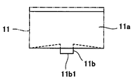
- FIG. 2 is a side view of the tool 11.
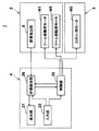
- FIG. 3 is a functional block diagram of the joining apparatus 1 of FIG.
- the component W spot-joined to the joining apparatus 1 is provided with the 1st board
- the joining device 1 continuously spot-joins the stacked plate members W1 and W2 by friction stir spot joining at a plurality of joining positions.
- the joining device 1 includes a joining unit 2, an articulated robot 3, and a control device 4.
- the joining unit 2 includes a frame part 5, a unit body part 6, a backing part 7, and a load detection part 8.
- the frame portion 5 has a C-shaped or inverted C-shaped appearance in a side view, supports the unit main body portion 6 and the backing portion 7, and is supported by the articulated robot 3.
- the external shape of the frame part 5 in side view is not limited, For example, I shape may be sufficient.
- the unit main body 6 includes a rotary shaft 9, a friction stir spot welding tool 11 (hereinafter simply referred to as a tool 11), a tool moving (elevating / lowering) motor M1, a tool rotating motor M2, and a joining unit controller. 12 and a moving mechanism 13.
- the rotating shaft portion 9 extends from the housing of the unit main body portion 6 toward the backing portion 7 and is provided so as to be able to approach or separate from the backing portion 7 by the moving mechanism 13.
- a holder is provided at one axial end located distal to the moving mechanism 13 of the rotary shaft portion 9 to hold the tool 11 detachably.
- the tool 11 is provided on the surface of the second plate W2 opposite to the first plate W1 so as to be in contact with or separated from the first plate W1.
- the tool 11 has a tool body 11a and a protrusion 11b.
- the protruding portion 11b is formed in a pin shape that protrudes from the tool main body portion 11a toward the backing portion 7.
- the joining apparatus 1 includes a tool moving motor M1 as a driving unit that drives the moving mechanism 13 so that the tool 11 approaches or separates from the backing unit 7, and the tool 11 is driven to rotate about its axis.
- a tool rotating motor M2 is provided as a driving unit.
- the tool moving motor M1 and the tool rotating motor M2 are built in the housing of the unit main body 6 together with the moving mechanism 13.
- the moving mechanism 13 is driven, and the rotating shaft portion 9 and the tool 11 are moved in the axial direction of the rotating shaft portion 9 so as to approach or separate from the backing portion 7.
- the rotating motor M ⁇ b> 2 is driven, the rotating shaft portion 9 and the tool 11 are driven to rotate around the axis of the rotating shaft portion 9.
- Each drive of the tool moving motor M1 and the tool rotating motor M2 is controlled by the control device 4.
- the backing portion 7 is disposed so as to face the front end portion 11b1 of the tool 11 with the plate materials W1, W2 interposed therebetween, and has a cylindrical appearance extending from the frame portion 5 toward the unit main body portion 6 as an example.
- the first plate material W1 is supported from below.
- the tip portion 7a at one end in the axial direction of the backing portion 7 is in contact with the surface of the first plate material W1 opposite to the second plate material W2.
- the external appearance shape of the backing part 7 is not limited, For example, a rectangular parallelepiped shape may be sufficient.
- the load detection unit 8 is built in the backing unit 7.
- the load detection part 8 is a load sensor as an example, and here is a load cell.
- the load detection unit 8 detects the applied pressure of the tool 11 received through the plate materials W1 and W2.
- the output signal of the load detection unit 8 is transmitted to the breakage detection unit 26 of the control device 4 (see FIG. 3).
- the articulated robot 3 has a robot motor M3 and moves the joining unit 2 to a predetermined position.
- the driving of the robot motor M3 is controlled by the control device 4.
- the robot motor M3 may include a plurality of motors.
- the joining apparatus 1 includes a moving mechanism 13, a tool moving motor M1, and a robot motor M3 as a position adjusting unit 20 that adjusts the relative position between the tool 11 and the second plate material W2.
- the control device 4 is a computer including a CPU, a ROM, a RAM, and the like, and controls each operation of the joining unit 2 and the articulated robot 3.
- the control device 4 includes a display unit 21, an input unit 22, a control unit 25, and a breakage detection unit 26.
- the display unit 21 is a liquid crystal display as an example, and displays predetermined information to the operator.
- the input unit 22 receives information input by the operator.
- a predetermined control program is stored in the ROM, and the RAM is configured to be able to store setting information input via the input unit 22.
- the setting information includes, for example, information on each plate thickness value of the plate materials W1 and W2 and information on each joining position.
- the control unit 25 controls each of the motors M1 to M3 based on the control program.
- the breakage detection unit 26 receives the output signal of the load detection unit 8 and controls the control unit 25 based on the control program.
- the breakage detection unit 26 detects a breakage of the tool 11 (here, a breakage in which the protruding dimension of the protruding portion 11b is shortened).
- the joining apparatus 1 includes the breakage detection unit 26 that detects breakage of the tool 11.
- the breakage detection unit 26 is in a period from when the tip of the tool 11 (tip portion 11b1) comes into contact with the second plate member W2 until the tip of the tool 11 is disposed at a predetermined pushing position. Is configured to detect breakage of the tool 11 on the basis of the change amount ⁇ p of the pressurizing force that pressurizes the second plate member W2.
- FIG. 4 is an operation flowchart of the bonding apparatus 1 of FIG.
- a determination step S ⁇ b> 3 for determining breakage of the tool 11 is performed, and friction stirring is performed according to the determination result.
- a point joining step (hereinafter referred to as a joining step) S4 or a notification step S7 is performed.
- the breaking step S4 and the completion determination step S5 are sequentially performed.
- the tool moving step S6 is performed.
- FIG. 5 (a) to 5 (d) are cross-sectional views for explaining the respective steps of friction stir spot welding using the joining apparatus 1 of FIG.
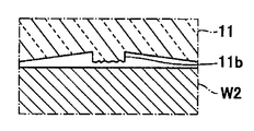
- FIG. 6 is a cross-sectional view of the broken tool 11.
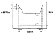
- FIG. 7 is a graph showing a change in the position of the tip 11b1 of the tool 11 and a change in the pressure value of the tool 11 detected by the load detection unit 8 in the joining apparatus 1 of FIG.
- the change in the position of the tip 11b1 at the first joining position is indicated by a curve L1
- the change in the pressurization value of the tool 11 detected by the load detection unit 8 at the first joining position is indicated by a curve L2. Yes.
- the operation time of the tool 11 at the first joining position is an approach movement section (between time t0 and t1) in which the tool 11 is moved to the second plate W2 side in time series, Detection section for detecting breakage of the tool 11 (between times t1 and t3), joining section for joining the plate materials W1, W2 with the tool 11 by friction stir spot welding (between times t3 and t4), and friction stir spot welding It is divided into separation movement sections (between times t4 and t6) for separating the tool 11 from the plate materials W1 and W2.
- the detection section includes a measurement section for measuring the applied pressure of the tool 11 (between time t1 and t2), and a determination section for determining whether the tool 11 is broken (between time t2 and t3). It is further divided into
- the operator inputs the setting information to the joining apparatus 1 through the input unit 22 and holds the plate materials W1 and W2 on a predetermined jig in a state of being overlapped.
- the breakage detection unit 26 causes the control unit 25 to control the position adjustment unit 20 so that the bonding unit 2 is moved to the first bonding position.
- the control unit 25 includes the tool 11 on the second plate material W2 side and the backing portion 7 on the first plate material W1 side, and the first plate material W1 is supported by the tip portion 7a of the backing portion 7.
- the position adjusting unit 20 is controlled. Thereby, the joining apparatus 1 is aligned with respect to the plate materials W1 and W2, and the alignment step S1 is performed.
- the breakage detection unit 26 causes the control unit 25 to control the tool rotation motor M2 so that the tool 11 is rotationally driven in the proximity movement section, and the tool 11 is the second one.
- the control unit 25 controls the position adjusting unit 20 to move the plate member W2 by the movement amount ⁇ h1.
- the tip 11b1 is moved from the reference (zeroing) position h0 to the first position h1, and the second plate W2 is opposite to the surface opposite to the first plate W1.
- Contact FIG. 5A).
- the breakage detection unit 26 causes the control unit 25 to control the tool rotation motor M2 so that the tool 11 is continuously driven to rotate in the measurement section. Further, the breakage detection unit 26 causes the control unit 25 to control the position adjustment unit 20 so that the tip end portion 11b1 is moved toward the second plate material W2 by the movement amount ⁇ h2. At this time, the distal end portion 11b1 is moved from the first position h1 toward the second position h2 toward the second plate material W2 rather than the first position h1, and the protruding portion 11b is slightly pushed into the second plate material W2 (FIG. 5). (B)).
- the breakage detection unit 26 controls the control unit 25 so that the tool 11 is in contact with the second plate material W2 or is disposed at a predetermined pushing position.
- the value of the pushing amount of the protruding portion 11b in the thickness direction of the second plate material W2 can be set as appropriate, but as an example, a value in the range of 0.1 mm to 0.5 mm is desirable. A value in the range of 2 mm to 0.4 mm is more desirable.
- the value of the pushing amount of the protruding portion 11b in the thickness direction of the second plate material W2 is set to 0.3 mm.
- the protrusion 11b When the tool 11 is not broken, the protrusion 11b is pushed into the second plate material W2 when the tip portion 11b1 is moved by the movement amount ⁇ h2 toward the second plate material W2, so that the pressing force of the tool 11 is increased.
- the load is transmitted to the load detection unit 8 via the plate materials W1 and W2, and the load detection unit 8 outputs the applied pressure of the tool 11 as an output signal in time series.
- the breakage detection unit 26 measures the pressurization value of the tool 11 against the plate materials W1 and W2 based on the output signal of the load detection unit 8, and the leading end portion 11b1 faces the second plate material W2. Then, the change amount ⁇ p of the applied pressure before and after being moved by the movement amount ⁇ h2 is calculated. Thereby, measurement process S2 is performed.
- the breakage detection unit 26 has the control unit 25 to control the position adjustment unit 20 so that the tool 11 moves toward the second plate at the first joining position.
- the tool 11 is broken by determining whether or not predetermined physical information is obtained by controlling the control unit 25 so as to be arranged at the contact position with the second plate member W2 or the predetermined pushing position. It is determined whether or not an error has occurred.
- the breakage detection unit 26 causes the control unit 25 to control the tool rotation motor M2 so that the tool 11 is continuously rotated, and the position of the tip end portion 11b1 is maintained at the second position h2.
- the position adjustment unit 20 is controlled by the control unit 25.
- the breakage detection unit 26 compares the change amount ⁇ p of the applied pressure with a predetermined threshold value ⁇ p0, and determines whether or not the change amount ⁇ p of the applied pressure equal to or greater than the threshold value ⁇ p0 is obtained as the physical information. By determining, it is determined whether or not the tool 11 is broken.
- the breakage detection unit 26 determines that the tool 11 is not broken when it is determined that the change amount ⁇ p of the pressing force equal to or greater than the threshold value ⁇ p0 is obtained, and otherwise determines that the tool 11 is broken. Thereby, determination process S3 is performed.
- the breakage detection unit 26 is configured to detect breakage of the tool 11 by obtaining the physical information.
- the plate materials W1 and W2 are frictionally stirred at the next joining position. Before spot joining, breakage of the tool 11 is detected.
- the time of a detection area can be set suitably, in order to shorten a series of work time concerning the friction stir spot welding in a some joining position, it is desirable that it is sufficiently short compared with the time of a joining area.
- the time of the detection interval is preferably in the range of 0.05 seconds to 1 second, more preferably in the range of 0.1 seconds to 0.5 seconds, and 0.15 More desirably, the time is in the range of not less than seconds and not more than 0.3 seconds.
- the detection section time is set to 0.2 seconds.
- the breakage detection unit 26 determines that the physical information has not been obtained (the breakage of the tool 11 has occurred), the first joining position among the plurality of joining positions of the plate members W1 and W2. And the control part 25 is made to control at least one of the tool rotation motor M2 and the position adjustment part 20 so that the friction stir spot joining using the tool 11 in the remaining joining positions may be stopped.
- the breakage detection unit 26 causes the control unit 25 to control the tool rotation motor M2 so that the rotation drive of the tool 11 is stopped, and the position of the tip 11b1 of the protrusion 11b is at least from the second position h2.
- the control unit 25 controls the position adjustment unit 20 to return to the reference position h0.
- the breakage detection unit 26 displays on the display unit 21 that the friction stir spot welding has been stopped, and notifies the operator. Thereby, notification process S7 is performed.
- the breakage detection unit 26 may notify the operator that the friction stir spot welding has been stopped by issuing a warning sound without using the display unit 21.
- the breakage detection unit 26 determines that the physical information has been obtained (no breakage of the tool 11 has occurred)
- the breakage detection unit 26 is brought into contact with the second plate material W2 at the 1 joining position.
- the control unit 25 controls the tool rotation motor M2 and the position adjustment unit 20 so that the tool 11 is pushed forward to the second plate member and the plate members W1 and W2 are joined to the friction stir point.
- the breakage detection unit 26 controls the tool 11 at the first joining position with the control unit 25 controlling the tool rotation motor M2 so that the tool 11 is continuously driven to rotate.
- the position adjustment unit 20 is controlled by the control unit 25 so that the tool 11 is pushed forward to the second plate material W2 while being in contact with the second plate material W2 (see FIG. 7). At this time, the controller 25 moves the tip 11b1 from the second position h2 to the third position h3 toward the second plate W2 from the second position h2, and the protrusion 11b is further pushed into the second plate W2.
- the position adjustment unit 20 is controlled so as to be That is, as shown by a curve L2 in FIG. 7, the plate members W1, W2 are pressed at a pressure value larger than the maximum pressure value when the plate materials W1, W2 are pressed by the tool 11 in the measurement section. As described above, the control unit 25 controls the position adjustment unit 20.
- the rotationally driven tool 11 is pushed forward to the second plate material W2, and the protrusion 11b is pushed into the plate materials W1 and W2, whereby the plate materials W1 and W2 are subjected to friction stir spot bonding at the joint position (FIG. 5). (D)). Thereby, joining process S4 is performed.
- the breakage detection unit 26 controls the control unit 25 to control the tool rotation motor M2 so that the tool 11 is continuously driven in the separation movement section, and from time t4 to time t5.
- the position of the tip portion 11b1 is returned from the third position h3 to the first position h1, the tool 11 is pulled out from the plate materials W1 and W2, and the position of the tip portion 11b1 is the first position between time t5 and t6.
- the control unit 25 controls the position adjusting unit 20 to return from h1 to the reference position h0.
- the rotation speed of the tool 11 in each of the steps S2 to S4 is set to the same value, but the rotation speed of the tool 11 in the measurement process S2 and the determination process S3 and the rotation speed of the tool 11 in the joining process S4. They may be different from each other. For example, you may set so that the rotation speed of the tool 11 in joining process S4 may become larger than the rotation speed of the tool 11 in measurement process S2 and determination process S3.
- the breakage detection unit 26 performs a completion determination step S5 for determining whether or not the bonding step S4 has been completed at all bonding positions after the bonding step S4 is completed.
- the breakage detection unit 26 is positioned in the control unit 25 so that the tool 11 is moved to the next joining position.
- the adjustment unit 20 is controlled.
- the breakage detection unit 26 determines that the joining step S4 of the plate materials W1 and W2 at all joining positions is completed in the completion determination step S5, the operation flow ends.
- the joining apparatus 1 since it is determined whether or not the tool 11 is broken at one joining position, for example, the tool 11 is moved to a predetermined position, and the test piece is pressurized with the tool 11. After determining whether or not the tool 11 is broken, the tool 11 may not be moved to the joining position of the plate materials W1 and W2.
- breakage detection unit 26 causes the control unit 25 to control the tool rotation motor M2 so that the breakage detection unit 26 detects breakage of the tool 11 in a state where the tool 11 is rotationally driven. If no breakage is detected, the plate members W1, W2 can be quickly friction stir spot joined at each joining position.
- the breakage detection unit 26 detects breakage of the tool 11 before joining the friction stir spot at one joining position, when the breakage of the tool 11 is detected, the breakage detection unit 26 breaks at the one joining position.
- the tool 11 can prevent the plate materials W1 and W2 from being damaged.
- the tool when the tool breaks, the tool is relatively often broken so that the protruding portion of the tool remains inside the plate when the tool is pulled out from the plate.
- the joining device the tool is pulled out from the plate material immediately after the friction stir spot joining at one joining position, so that the tool breakage causes the torque and tool position due to the turning axis current of the tool rotating motor to change.
- it is difficult to detect such a change, and it may not be possible to detect breakage of the tool.
- the joining operation is performed at the next joining position while the tool is broken, there is a risk of damaging the joining device and the plate material.
- the method of detecting the breakage generated in the tool after the friction stir spot welding at the preceding joining position occurs before the friction stir spot joining at the next joining position occurs in the joining device or the plate material. It is very effective in preventing damage.
- the breakage detection unit 26 performs the determination, the setting of the zero point position in the output signal of the load detection unit 8 is deviated, or the positions of the plate materials W1 and W2 with respect to the backing unit 7 are deviated. It is conceivable that the output signal of the load detector 8 is output regardless of the applied pressure. On the other hand, since the change amount ⁇ p of the pressing force is used as the physical information used for the determination of the breakage detection unit 26 in the bonding apparatus 1, for example, the measured pressurization value of the tool 11 deviates from the actual value. Even if it is, the breakage detection part 26 can detect the breakage of the tool 11 satisfactorily. Therefore, the breakage detection unit 26 can improve the breakage detection accuracy of the tool 11 as compared with the case where the breakage of the tool 11 is detected by capturing a fixed value of the applied pressure.
- the breakage detection unit 26 stagnates the leading end portion 11b1 of the protruding portion 11b of the tool 11 at a predetermined position (second position h2), so that the protruding portion 11b is in contact with the second plate material W2. Since it is determined whether or not the tool 11 is broken by determining whether or not the change amount ⁇ p of the pressing force is obtained based on the presence or absence of contact, it is possible to prevent such erroneous determination from occurring.
- the breakage detection portion 26 can calculate the amount of change ⁇ p in the applied pressure. Therefore, the breakage detection unit 26 can appropriately determine whether or not a breakage has occurred in the tool 11.
- the breakage detection unit 26 calculates the change ⁇ p in the applied pressure from the output signal of the load detecting unit 8 that receives the applied pressure of the tool 11 from the surface of the first plate W1 opposite to the second plate W2. Since the calculated change amount ⁇ p of the applied pressure is compared with the threshold value ⁇ p0, it is possible to appropriately determine whether or not the change amount ⁇ p of the applied force that is equal to or greater than the threshold value ⁇ p0 is obtained. .
- the breakage detection unit 26 rotates the tool moving motor M1 when the tip 11b1 is moved by the movement amount ⁇ h2 toward the second plate member W2 while the tool 11 is rotationally driven in the measurement step S2.
- a current value necessary for rotating the shaft may be measured, and a change amount ⁇ T of the torque of the tool moving motor M1 may be calculated as a change amount of the pressing force of the tool 11.
- the rotation resistance value at the second position h2 of the tool rotation motor M2 when the tool 11 is broken is equal to the rotation resistance value at the second position h2 of the tool rotation motor M2 when the tool 11 is not broken. It is considered to be smaller than the value. Therefore, the breakage detection unit 26 rotates the tool rotation motor M2 when the tip 11b1 is moved toward the second plate member W2 by the movement amount ⁇ h2 in the measurement step S2 while the tool 11 is rotationally driven.
- the torque change amount ⁇ T is calculated by measuring a current value necessary for rotating the shaft, and in the determination step S3, the torque change amount ⁇ T is compared with a predetermined threshold value ⁇ T0, and the threshold value ⁇ T0 or more is compared. If it is determined that the torque change amount ⁇ T is obtained, it can be determined that the tool 11 is not broken, and if not, it can be determined that the tool 11 is broken.
- the load detection unit 8 is not limited to a load sensor, and may be a strain gauge.
- a strain gauge can be attached to the outside or the inside of the frame portion 5 so that the strain generated in the frame portion 5 is detected when the plate members W1 and W2 are pressed by the tool 11.
- the breakage detector 26 can calculate the change ⁇ p in the applied pressure from the output signal output from the strain gauge.
- the breakage detection unit 26 is measured by the output signal of the load detection unit 8 while the tip end part 11b1 is moved toward the second plate member W2 at least one of the movement amount ⁇ h1 and the movement amount ⁇ h2 in the measurement step S2.
- the maximum pressurization value F max of the tool 11 may be compared with a predetermined threshold value ⁇ F0 in the determination step S3.
- breakage detecting unit 26 determines that the broken tool 11 does not occur when it is determined that the threshold ⁇ F0 or more of the maximum pressurization value F max is obtained, otherwise It can be determined that the tool 11 is broken.
- FIG. 8 is a partial side view of the joining apparatus 101 according to the modification.
- FIG. 9 is a graph showing a change in the position of the tip 11b1 of the tool 11 and a change in the current value detected by the breakage detection unit 26 in the joining apparatus 101 of FIG.
- a change in the position of the tip end portion 11b1 is indicated by a curve L3
- a change in the current value detected by the breakage detection unit 26 is indicated by a curve L4.
- the breakage detection unit 26 is configured to detect breakage of the tool 11 based on energization at the time of contact between the tip end (tip portion 11b1) of the tool 11 and the second plate member W2. .
- the breakage detection unit 26 is configured to detect breakage of the tool 11 by obtaining, as the physical information, energization at the time of contact between the tip of the tool 11 and the second plate material W2.
- the operation time of the tool 11 at the first joining position is, in time series, the approaching movement section from time t0 to t1, the detection section from time t1 to t2, and the time t2 to t3. And a separation movement section between times t3 and t5.
- the tool 11 and the backing portion 7 are both conductive. As shown in FIG. 8, the tool 11 and the backing part 7 are both connected to a power source 30.
- the power source 30 is an AC power source as an example, but may be a DC power source.
- the breakage detection unit 26 monitors the energization or non-energization state between the tool 11 and the backing unit 7 via the plate materials W1 and W2.
- the breakage detection unit 26 also functions as a current detection device that detects a current flowing between the tool 11 and the backing unit 7 via the plate materials W1 and W2.
- the breakage detection unit 26 causes the control unit 25 to control the tool rotation motor M2 so that the tool 11 is rotationally driven in the movement section, and the tip end portion 11b1 is the second one.
- the control unit 25 controls the position adjusting unit 20 to move the plate member W2 by the movement amount ⁇ h1.
- the tip portion 11b1 is moved from the reference position h0 to the first position h1, and when the tool 11 is not broken, the tip portion 11b1 contacts the surface of the second plate material W2 opposite to the first plate material W1. .
- the breakage detection unit 26 measures the value i of the current flowing between the tool 11 and the backing unit 7 via the plate materials W1 and W2. Thereby, measurement process S2 is performed. Further, in the detection section, the breakage detection unit 26 determines whether or not the tool 11 has been broken by determining whether or not the current value i measured in the measurement step S2 is a predetermined current value i0. To do. Thereby, determination process S3 is performed. The breakage detection unit 26 determines that the tool 11 is not broken when it is determined that the current value i is a predetermined current value i0, and otherwise determines that the tool 11 is broken. To do. The current value i0 can be set as appropriate.
- the current value i0 is sufficiently larger than the current value i flowing between the tool 11 and the backing portion 7 via the plate materials W1 and W2. It is desirable that the value be small.
- the current value i0 is set to 0 mA.
- the joining device 101 can detect the breakage of the tool 11 simply by bringing the tool 11 into contact with the second plate material W2, so that it is possible to satisfactorily prevent the second plate material W2 from being pressed and damaged by the broken tool 11. it can.
- the present invention is not limited to the above-described embodiments and modifications, and the configuration or method thereof can be changed, added, or deleted without departing from the spirit of the present invention.
- the structure manufactured by friction stir spot welding may be a part or body other than the automobile door part, or a structure other than the automobile (for example, an aircraft part or body).
Landscapes
- Engineering & Computer Science (AREA)
- Mechanical Engineering (AREA)
- Pressure Welding/Diffusion-Bonding (AREA)
Abstract
Priority Applications (5)
| Application Number | Priority Date | Filing Date | Title |
|---|---|---|---|
| US15/770,221 US10974344B2 (en) | 2015-10-21 | 2016-10-14 | Friction stir spot joining apparatus and friction stir spot joining method |
| JP2017546401A JP6329707B2 (ja) | 2015-10-21 | 2016-10-14 | 摩擦撹拌点接合装置及び摩擦撹拌点接合方法 |
| EP16857090.1A EP3366410A4 (fr) | 2015-10-21 | 2016-10-14 | Dispositif et procédé de soudage par point avec friction et agitation |
| CN201680061690.9A CN108136537B (zh) | 2015-10-21 | 2016-10-14 | 摩擦搅拌点接合装置及摩擦搅拌点接合方法 |
| KR1020187013131A KR102031895B1 (ko) | 2015-10-21 | 2016-10-14 | 마찰 교반 점 접합 장치 및 마찰 교반 점 접합 방법 |
Applications Claiming Priority (2)
| Application Number | Priority Date | Filing Date | Title |
|---|---|---|---|
| JP2015-207353 | 2015-10-21 | ||
| JP2015207353 | 2015-10-21 |
Publications (1)
| Publication Number | Publication Date |
|---|---|
| WO2017068767A1 true WO2017068767A1 (fr) | 2017-04-27 |
Family
ID=58558061
Family Applications (1)
| Application Number | Title | Priority Date | Filing Date |
|---|---|---|---|
| PCT/JP2016/004589 WO2017068767A1 (fr) | 2015-10-21 | 2016-10-14 | Dispositif et procédé de soudage par point avec friction et agitation |
Country Status (6)
| Country | Link |
|---|---|
| US (1) | US10974344B2 (fr) |
| EP (1) | EP3366410A4 (fr) |
| JP (1) | JP6329707B2 (fr) |
| KR (1) | KR102031895B1 (fr) |
| CN (1) | CN108136537B (fr) |
| WO (1) | WO2017068767A1 (fr) |
Families Citing this family (4)
| Publication number | Priority date | Publication date | Assignee | Title |
|---|---|---|---|---|
| JP6554029B2 (ja) * | 2015-11-24 | 2019-07-31 | 川崎重工業株式会社 | 摩擦撹拌点接合装置及び摩擦撹拌点接合方法 |
| EP3981537A1 (fr) * | 2017-09-04 | 2022-04-13 | Kawasaki Jukogyo Kabushiki Kaisha | Procédé de fonctionnement d'un dispositif de soudage par friction-malaxage à double action, et dispositif de soudage par friction-malaxage à double action |
| JP7181113B2 (ja) * | 2019-02-08 | 2022-11-30 | トヨタ自動車株式会社 | 異種金属接合方法 |
| CN115338530B (zh) * | 2022-08-04 | 2024-04-30 | 北京九天行歌航天科技有限公司 | 一种基于力位扭矩的搅拌工具断针监测装置及方法 |
Citations (3)
| Publication number | Priority date | Publication date | Assignee | Title |
|---|---|---|---|---|
| JPS63288647A (ja) * | 1987-05-21 | 1988-11-25 | Dai Showa Seiki Kk | 工具破損検出方法 |
| JP2006212657A (ja) * | 2005-02-02 | 2006-08-17 | Kawasaki Heavy Ind Ltd | 摩擦撹拌接合装置用接合ツール |
| JP2010188367A (ja) * | 2009-02-17 | 2010-09-02 | Honda Motor Co Ltd | 摩擦撹拌接合のツール挿入方法 |
Family Cites Families (9)
| Publication number | Priority date | Publication date | Assignee | Title |
|---|---|---|---|---|
| US6050475A (en) * | 1998-05-29 | 2000-04-18 | Mcdonnell Douglas Corporation | Method and apparatus for controlling downforce during friction stir welding |
| US6421578B1 (en) * | 1999-02-12 | 2002-07-16 | Lockheed Martin Corporation | Stir-friction hot working control system |
| JP3867475B2 (ja) * | 2000-04-28 | 2007-01-10 | マツダ株式会社 | 金属部材の処理方法 |
| JP4050478B2 (ja) * | 2001-03-29 | 2008-02-20 | マツダ株式会社 | 摩擦撹拌を用いた加工制御方法、並びに当該方法を実行するコンピュータプログラム並びに当該コンピュータプログラムを格納した記憶媒体 |
| JP3471338B2 (ja) * | 2001-07-30 | 2003-12-02 | 川崎重工業株式会社 | 摩擦攪拌接合装置 |
| US6908690B2 (en) * | 2002-04-29 | 2005-06-21 | The Boeing Company | Method and apparatus for friction stir welding |
| JP3498086B1 (ja) * | 2003-05-14 | 2004-02-16 | 川崎重工業株式会社 | 摩擦撹拌接合方法および摩擦撹拌接合装置 |
| DE102005032170A1 (de) * | 2005-07-09 | 2007-01-11 | Technische Universität Ilmenau | Rührreibschweißwerkzeug und Verfahren und Anordnung zur online-Kontrolle eines Rührreibschweißprozesses |
| EP2965858A1 (fr) * | 2014-07-11 | 2016-01-13 | NELA Razvojni center d.o.o. Podruznica Vincarje | Détection de rupture d'outil en temps réel pendant le processus de soudage par friction-malaxage |
-
2016
- 2016-10-14 EP EP16857090.1A patent/EP3366410A4/fr not_active Withdrawn
- 2016-10-14 JP JP2017546401A patent/JP6329707B2/ja active Active
- 2016-10-14 WO PCT/JP2016/004589 patent/WO2017068767A1/fr active Application Filing
- 2016-10-14 US US15/770,221 patent/US10974344B2/en active Active
- 2016-10-14 KR KR1020187013131A patent/KR102031895B1/ko active IP Right Grant
- 2016-10-14 CN CN201680061690.9A patent/CN108136537B/zh active Active
Patent Citations (3)
| Publication number | Priority date | Publication date | Assignee | Title |
|---|---|---|---|---|
| JPS63288647A (ja) * | 1987-05-21 | 1988-11-25 | Dai Showa Seiki Kk | 工具破損検出方法 |
| JP2006212657A (ja) * | 2005-02-02 | 2006-08-17 | Kawasaki Heavy Ind Ltd | 摩擦撹拌接合装置用接合ツール |
| JP2010188367A (ja) * | 2009-02-17 | 2010-09-02 | Honda Motor Co Ltd | 摩擦撹拌接合のツール挿入方法 |
Non-Patent Citations (1)
| Title |
|---|
| See also references of EP3366410A4 * |
Also Published As
| Publication number | Publication date |
|---|---|
| KR20180059943A (ko) | 2018-06-05 |
| US20180297145A1 (en) | 2018-10-18 |
| JPWO2017068767A1 (ja) | 2018-03-01 |
| EP3366410A1 (fr) | 2018-08-29 |
| EP3366410A4 (fr) | 2019-09-04 |
| CN108136537A (zh) | 2018-06-08 |
| KR102031895B1 (ko) | 2019-10-14 |
| US10974344B2 (en) | 2021-04-13 |
| JP6329707B2 (ja) | 2018-05-23 |
| CN108136537B (zh) | 2020-04-14 |
Similar Documents
| Publication | Publication Date | Title |
|---|---|---|
| JP6329707B2 (ja) | 摩擦撹拌点接合装置及び摩擦撹拌点接合方法 | |
| CN111107957B (zh) | 复动式摩擦搅拌接合装置的运行方法以及复动式摩擦搅拌接合装置 | |
| JP6223535B2 (ja) | 超音波溶接品質判断装置および方法 | |
| JP5196642B2 (ja) | 抵抗溶接法の監視方法およびその方法を実施するための装置 | |
| EP2145718A2 (fr) | Soudeuse à ultrasons et corps assemblé obtenu grâce à la soudeuse | |
| JP2000288743A (ja) | 抵抗溶接機用制御装置 | |
| WO2019159815A1 (fr) | Procédé de détection de projection lors d'un soudage par résistance électrique, et appareil s'y rapportant | |
| JP5143873B2 (ja) | 超音波接合制御装置及び超音波接合制御方法 | |
| US9387551B2 (en) | Method, system, and computer program product for simulating friction stir welding | |
| JP6339292B2 (ja) | スポット溶接方法及びその装置 | |
| JP4535739B2 (ja) | スポット溶接装置 | |
| JP5038989B2 (ja) | 超音波金属接合機 | |
| JP4175484B2 (ja) | 摩擦攪拌接合方法とその接合装置およびその摩擦接合体 | |
| JP3810754B2 (ja) | 摩擦攪拌接合方法とその接合装置およびその摩擦接合体 | |
| JP2001105159A (ja) | 超音波接合装置 | |
| JP3290977B2 (ja) | 摩擦撹拌接合における異常停止制御方法 | |
| JP5091610B2 (ja) | 摩擦接合システム及び摩擦接合方法 | |
| JP2001096370A (ja) | 抵抗溶接装置 | |
| JP2002205174A (ja) | 抵抗溶接機および抵抗溶接機の加圧制御方法 | |
| JP2012055907A (ja) | 超音波接合制御装置及び超音波接合制御方法 | |
| JP2008155240A (ja) | 超音波接合の接合品質判別方法 | |
| JPH10216963A (ja) | 摩擦圧接方法 | |
| JP6164862B2 (ja) | シーム溶接方法及びシステム | |
| JP7056451B2 (ja) | 抵抗溶接装置 | |
| JP4445279B2 (ja) | スポット溶接の溶接制御方法及び溶接制御装置 |
Legal Events
| Date | Code | Title | Description |
|---|---|---|---|
| 121 | Ep: the epo has been informed by wipo that ep was designated in this application |
Ref document number: 16857090 Country of ref document: EP Kind code of ref document: A1 |
|
| ENP | Entry into the national phase |
Ref document number: 2017546401 Country of ref document: JP Kind code of ref document: A |
|
| WWE | Wipo information: entry into national phase |
Ref document number: 15770221 Country of ref document: US |
|
| NENP | Non-entry into the national phase |
Ref country code: DE |
|
| ENP | Entry into the national phase |
Ref document number: 20187013131 Country of ref document: KR Kind code of ref document: A |
|
| WWE | Wipo information: entry into national phase |
Ref document number: 2016857090 Country of ref document: EP |