WO2017065286A1 - ガラス樹脂積層体 - Google Patents
ガラス樹脂積層体 Download PDFInfo
- Publication number
- WO2017065286A1 WO2017065286A1 PCT/JP2016/080580 JP2016080580W WO2017065286A1 WO 2017065286 A1 WO2017065286 A1 WO 2017065286A1 JP 2016080580 W JP2016080580 W JP 2016080580W WO 2017065286 A1 WO2017065286 A1 WO 2017065286A1
- Authority
- WO
- WIPO (PCT)
- Prior art keywords
- glass
- less
- plate
- value
- resin
- Prior art date
- Legal status (The legal status is an assumption and is not a legal conclusion. Google has not performed a legal analysis and makes no representation as to the accuracy of the status listed.)
- Ceased
Links
Images




Classifications
-
- C—CHEMISTRY; METALLURGY
- C03—GLASS; MINERAL OR SLAG WOOL
- C03C—CHEMICAL COMPOSITION OF GLASSES, GLAZES OR VITREOUS ENAMELS; SURFACE TREATMENT OF GLASS; SURFACE TREATMENT OF FIBRES OR FILAMENTS MADE FROM GLASS, MINERALS OR SLAGS; JOINING GLASS TO GLASS OR OTHER MATERIALS
- C03C21/00—Treatment of glass, not in the form of fibres or filaments, by diffusing ions or metals in the surface
- C03C21/001—Treatment of glass, not in the form of fibres or filaments, by diffusing ions or metals in the surface in liquid phase, e.g. molten salts, solutions
- C03C21/002—Treatment of glass, not in the form of fibres or filaments, by diffusing ions or metals in the surface in liquid phase, e.g. molten salts, solutions to perform ion-exchange between alkali ions
-
- B—PERFORMING OPERATIONS; TRANSPORTING
- B32—LAYERED PRODUCTS
- B32B—LAYERED PRODUCTS, i.e. PRODUCTS BUILT-UP OF STRATA OF FLAT OR NON-FLAT, e.g. CELLULAR OR HONEYCOMB, FORM
- B32B17/00—Layered products essentially comprising sheet glass, or glass, slag, or like fibres
- B32B17/06—Layered products essentially comprising sheet glass, or glass, slag, or like fibres comprising glass as the main or only constituent of a layer, next to another layer of a specific material
-
- B—PERFORMING OPERATIONS; TRANSPORTING
- B32—LAYERED PRODUCTS
- B32B—LAYERED PRODUCTS, i.e. PRODUCTS BUILT-UP OF STRATA OF FLAT OR NON-FLAT, e.g. CELLULAR OR HONEYCOMB, FORM
- B32B7/00—Layered products characterised by the relation between layers; Layered products characterised by the relative orientation of features between layers, or by the relative values of a measurable parameter between layers, i.e. products comprising layers having different physical, chemical or physicochemical properties; Layered products characterised by the interconnection of layers
- B32B7/04—Interconnection of layers
- B32B7/12—Interconnection of layers using interposed adhesives or interposed materials with bonding properties
-
- C—CHEMISTRY; METALLURGY
- C03—GLASS; MINERAL OR SLAG WOOL
- C03C—CHEMICAL COMPOSITION OF GLASSES, GLAZES OR VITREOUS ENAMELS; SURFACE TREATMENT OF GLASS; SURFACE TREATMENT OF FIBRES OR FILAMENTS MADE FROM GLASS, MINERALS OR SLAGS; JOINING GLASS TO GLASS OR OTHER MATERIALS
- C03C17/00—Surface treatment of glass, not in the form of fibres or filaments, by coating
- C03C17/28—Surface treatment of glass, not in the form of fibres or filaments, by coating with organic material
- C03C17/32—Surface treatment of glass, not in the form of fibres or filaments, by coating with organic material with synthetic or natural resins
-
- B—PERFORMING OPERATIONS; TRANSPORTING
- B32—LAYERED PRODUCTS
- B32B—LAYERED PRODUCTS, i.e. PRODUCTS BUILT-UP OF STRATA OF FLAT OR NON-FLAT, e.g. CELLULAR OR HONEYCOMB, FORM
- B32B2457/00—Electrical equipment
- B32B2457/20—Displays, e.g. liquid crystal displays, plasma displays
- B32B2457/202—LCD, i.e. liquid crystal displays
-
- G—PHYSICS
- G02—OPTICS
- G02F—OPTICAL DEVICES OR ARRANGEMENTS FOR THE CONTROL OF LIGHT BY MODIFICATION OF THE OPTICAL PROPERTIES OF THE MEDIA OF THE ELEMENTS INVOLVED THEREIN; NON-LINEAR OPTICS; FREQUENCY-CHANGING OF LIGHT; OPTICAL LOGIC ELEMENTS; OPTICAL ANALOGUE/DIGITAL CONVERTERS
- G02F1/00—Devices or arrangements for the control of the intensity, colour, phase, polarisation or direction of light arriving from an independent light source, e.g. switching, gating or modulating; Non-linear optics
- G02F1/01—Devices or arrangements for the control of the intensity, colour, phase, polarisation or direction of light arriving from an independent light source, e.g. switching, gating or modulating; Non-linear optics for the control of the intensity, phase, polarisation or colour
- G02F1/13—Devices or arrangements for the control of the intensity, colour, phase, polarisation or direction of light arriving from an independent light source, e.g. switching, gating or modulating; Non-linear optics for the control of the intensity, phase, polarisation or colour based on liquid crystals, e.g. single liquid crystal display cells
- G02F1/133—Constructional arrangements; Operation of liquid crystal cells; Circuit arrangements
- G02F1/1333—Constructional arrangements; Manufacturing methods
- G02F1/133308—Support structures for LCD panels, e.g. frames or bezels
- G02F1/133331—Cover glasses
-
- G—PHYSICS
- G02—OPTICS
- G02F—OPTICAL DEVICES OR ARRANGEMENTS FOR THE CONTROL OF LIGHT BY MODIFICATION OF THE OPTICAL PROPERTIES OF THE MEDIA OF THE ELEMENTS INVOLVED THEREIN; NON-LINEAR OPTICS; FREQUENCY-CHANGING OF LIGHT; OPTICAL LOGIC ELEMENTS; OPTICAL ANALOGUE/DIGITAL CONVERTERS
- G02F2201/00—Constructional arrangements not provided for in groups G02F1/00 - G02F7/00
- G02F2201/50—Protective arrangements
- G02F2201/503—Arrangements improving the resistance to shock
Definitions
- the present invention relates to a glass resin laminate.
- So-called chemically tempered glass is used as a cover member in various applications such as electronic devices typified by smartphones and electronic paper, in-vehicle display members provided in automobiles and trains, solar cell modules, lighting, and the like.
- the thickness of glass has been reduced for the purpose of reducing the weight of equipment and the like in which glass is used.
- CT CS ⁇ DOL / (t ⁇ 2 ⁇ DOL)
- a method for managing the fragility of tempered glass by setting the CT value within a certain numerical range is disclosed.
- This value of CT 1 is proposed as the upper limit of the value of the median tension CT and is the critical value for the onset of unacceptable vulnerability.
- the design flexibility is said to be limited based on equation (2).
- this invention aims at providing the glass resin laminated body which can set CS and DOL of a cover glass to a higher value than before, and a user can use it temporarily with sufficient operativity even after breaking. To do.
- this invention provides the following glass resin laminated bodies.
- a glass resin laminate comprising a plate-like glass having a compression stress layer formed on the main surface and a resin layer provided on the plate-like glass, wherein the surface compression stress on the main surface of the plate glass is 200 MPa or more and the depth of the compressive stress layer is 3 ⁇ m or more, and the internal tensile stress CT (MPa) and the plate thickness t (mm) of the sheet glass are expressed by the following equations (4) and (5). Fills the glass resin laminate.
- the disclosed technology it is possible to provide a glass resin laminate in which the CS and DOL of the cover glass can be set to higher values than before and can be used by the user with good operability even after being broken.
- FIG. 1 is a diagram for explaining the cracking behavior of a sheet glass alone.
- FIG. 2 is a diagram for explaining the cracking behavior of the glass sheet in a configuration in which a resin is interposed between the cover glass and the housing of the electronic device.
- FIG. 3 is a schematic diagram showing one configuration of the glass resin laminate according to the present embodiment.
- FIG. 4 is a schematic diagram of the cracking behavior of a glass resin laminate including a plate glass having a CT value not exceeding the CT 4 value.
- FIG. 5 is a schematic diagram of the cracking behavior of a glass resin laminate including a plate glass having a CT value exceeding the CT 4 value.
- FIG. 6 is a view for explaining a method for measuring the surface level difference of the sheet glass when the resin layer is interposed between the sheet glass and the electronic device casing in the glass resin laminate according to the present embodiment.
- FIG. 7 is a view for explaining the relationship between the plate thickness of the glass sheet contained in the glass resin laminates of Examples 1 to 47, CT 1 value, and CT 4 value.
- the plate-like glass 10 is disposed on the electronic device casing 40 via the resin layer 20.
- the inventors of the present application have intensively studied that the cracking behavior of the cover glass is different when the resin layer is interposed between the cover glass and the electronic device casing (particularly, the liquid crystal display member). I found it. For example, in a configuration in which a resin is interposed between a sheet glass as shown in FIG. 1 and a cover glass and a housing of an electronic device as shown in FIG. 2, the cracking behavior of the sheet glass and the degree of scattering thereof was very different.
- the inventor of the present application has found that such operability problems can be solved by controlling the chemical strengthening characteristics of the cover glass, that is, the stress profile (attention point 2). Therefore, in the present embodiment, it is possible to set CS and DOL of the cover glass to higher values than before in consideration of the above-mentioned attention points 1 and 2, and the user can use it temporarily with good operability even after it is broken.
- a glass resin laminate is provided.
- the plate-like glass according to the present embodiment is usually plate-shaped, but it may be a flat plate or a glass plate subjected to bending.
- the manufacturing method of the plate glass according to the present embodiment is not particularly limited, and is a glass plate formed into a flat plate shape by a known glass forming method such as a float method, a fusion method, a slot down draw method, or the like glass.
- the raw material is put into a continuous melting furnace, the glass raw material is heated and melted preferably at 1500 to 1600 ° C., clarified, and then supplied to a molding apparatus, and then the molten glass is formed into a plate shape and slowly cooled. be able to.
- the plate glass preferably has a liquid phase viscosity of 130 dPa ⁇ s or more.
- the sheet glass according to the present embodiment has dimensions that can be formed by an existing forming method. That is, if it is formed by the float process, ribbon-like glass having a continuous float forming width can be obtained. Further, the sheet glass according to the present embodiment is finally cut into a size suitable for the purpose of use.
- the plate thickness t of the sheet glass according to the present embodiment is 2.0 mm or less in order to contribute to weight reduction. The thinner the glass, the lower the operability even if the internal tensile stress CT is increased to a higher value than before.
- the plate thickness t is preferably 1.5 mm or less, more preferably 1.0 mm or less, further preferably 0.7 mm or less, still more preferably 0.5 mm or less, particularly preferably 0.3 mm or less, and most preferably 0.2 mm. It is as follows.
- the thickness t of the sheet glass according to the present embodiment is preferably 0.05 mm or more in order to provide the compressive stress layer to a certain extent deep. If it is a plate-like glass with a plate thickness t of 0.05 mm or more, at least DOL can be set to 3 ⁇ m or more by chemical strengthening treatment.
- the plate thickness t is more preferably 0.07 mm or more, and still more preferably 0.1 mm or more. In order to obtain a larger DOL, the thickness t is preferably 0.1 mm or more. Thereby, when glass is greatly bent, it can prevent that it breaks from an end surface.
- the plate-like glass according to the present embodiment includes a cover glass for a touch panel display and a touch sensor glass, a cover glass for a liquid crystal television, a PC monitor, and the like provided in information devices such as a tablet PC, a notebook PC, a smartphone, and an electronic book reader. It can be used for a cover glass for automobile instrument panels, a cover glass for solar cells, an interior material for building materials, and a multilayer glass used for windows of buildings and houses. That is, it is the size of a display such as a tablet PC or a smartphone, or a cover glass for a solar cell, or a size corresponding to each application.
- the plate-like glass according to the present embodiment is generally cut into a rectangle, but other shapes such as a circle or a polygon can be used without any problem, and a glass subjected to drilling is also included.
- the plate glass according to the present embodiment is a chemically strengthened glass having a compressive stress layer on the glass surface layer by a chemical strengthening treatment.
- the surface compression stress (CS) of the sheet glass is preferably 200 MPa or more, and more preferably 300 MPa or more, 400 MPa or more, 500 MPa or more, 600 MPa or more, 700 MPa or more, 800 MPa or more, 900 MPa or more, 1000 MPa or more.
- CS is 200 MPa or more, scratches are less likely to occur on the glass surface.
- the DOL of the plate glass is preferably deep.
- the DOL is preferably 3 ⁇ m or more, more preferably 4 ⁇ m or more, 5 ⁇ m or more, 6 ⁇ m or more, 7 ⁇ m or more, 8 ⁇ m or more, 9 ⁇ m or more, 10 ⁇ m or more, 12 ⁇ m or more, 15 ⁇ m or more, or 20 ⁇ m or more.
- t is the thickness ( ⁇ m) of the sheet glass
- DOL is the depth of the compressive stress layer ( ⁇ m)
- CS is the surface compressive stress value (MPa)
- CS (x) is the depth of the sheet glass.
- It is a compressive stress value (MPa) at a position x in the direction, that is, a stress profile.
- the unit of CT is (MPa).
- Equation (1) is a calculation of CT applied to a chemically strengthened glass having a so-called complementary error function profile such that approximation to a linear function of the stress profile inside the glass (hereinafter also referred to as triangle approximation) is relatively acceptable. It is a formula.
- the error in the CT value obtained by Equation (1) and Equation (3) is small and within ⁇ 5% of the CT value obtained by Equation (1).
- the value of CT in equation (3) is entered.
- the CT value is obtained by equation (1).
- the error of the CT value obtained by the equations (1) and (3) is large, and the CT value of the equation (3) is within ⁇ 5% of the CT value obtained by the equation (1).
- Such a chemically strengthened glass is referred to as a chemically strengthened glass having a non-complementary error function profile.
- the CT value is obtained by equation (3).
- CS and DOL can be measured using a glass surface stress meter (FSM-6000LE manufactured by Orihara Seisakusho).
- CS (x) can be measured using a glass surface stress meter (FSM-6000LE / IR, manufactured by Orihara Seisakusho).
- the internal tensile stress CT of the sheet glass according to the present embodiment is preferably 30 MPa or more in order to bring CS or DOL closer to a more preferable value, 50 MPa or more, 70 MPa or more, 100 MPa or more, 120 MPa or more, 150 MPa. As mentioned above, it is more preferable that it is 200 Mpa or more. Further, in order to enable a material design different from the conventional one in order to preferably increase CS and DOL, the internal tensile stress CT is made larger than the CT 1 value determined by the equation (2), that is, “CT> ⁇ 38. 0.7 ⁇ ln (t) +48.2 ”(equation (5)).
- the operability of the glass resin laminate when a crack occurs on the surface of the sheet glass can be evaluated by the following operability index.
- the operability index was determined by allowing the Vickers indenter to fall freely from a height of 30 mm with respect to the surface of the glass sheet with a 10 g weight attached to a Vickers indenter (diamond regular square pyramid indenter with a facing angle of 136 degrees).
- the Vickers indenter is collided with the surface side of the plate glass at a speed of 0.8 m / sec, and is divided into three steps as shown in Table 1 depending on the surface step (unevenness).
- corrugation) after destruction is measured with the surface roughness and the contour shape measuring machine (Surfcom 1400D by Tokyo Seimitsu Co., Ltd.).
- the operability index is 2 or more, a glass resin laminate that can be used with good operability by the user even after the sheet glass is broken is preferable.
- a operability index of 3 is more preferable because the glass resin laminate can be used with good operability because the user cannot confirm cracks in the sheet glass with a finger.
- SiO 2 is known as a component that forms a network structure in the glass microstructure.
- the content of SiO 2 is preferably 60% or more, more preferably 61% or more, 62% or more, 63% or more, 64% or more, 65% or more, 66% or more, 67% or more.
- the content of SiO 2 is preferably 72% or less, more preferably 71% or less, 70% or less, or 69% or less.
- the content of SiO 2 is 60% or more, it is advantageous in terms of stability and weather resistance as glass.
- the content of SiO 2 is 72% or less, it is advantageous in terms of meltability and moldability.
- Al 2 O 3 has an effect of improving chemical strengthening characteristics in chemical strengthening, and particularly has a large effect of improving CS. It is also known as a component that improves the weather resistance of glass. Moreover, there exists an effect
- the content of Al 2 O 3 is preferably 1% or more, more preferably 3% or more, 5% or more, 7% or more, 9% or more, and further preferably 10% or more.
- the content of Al 2 O 3 is preferably 30% or less, more preferably 20% or less, 18% or less, 16% or less, 15% or less, or 14% or less.
- the content of Al 2 O 3 is 1% or more, a desired CS value can be obtained by ion exchange, and the effect of suppressing the intrusion of tin, the effect of stability against changes in water content, and the effect of promoting alkali removal Is obtained.
- the content of Al 2 O 3 is 30% or less, it is advantageous in that the DOL value does not become too large and the CT value can be suppressed to a certain value or less.
- MgO is a component that stabilizes the glass.
- the content of MgO is preferably 1% or more, more preferably 2% or more, 3% or more, and 4% or more. Further, the content of MgO is preferably 12% or less, more preferably 11% or less, 10% or less, 9% or less, 8% or less, or 7% or less.
- the content of MgO is 1% or more, the meltability at high temperature becomes good and devitrification hardly occurs.
- the content of MgO is 11% or less, the difficulty of devitrification is maintained, and a sufficient ion exchange rate is obtained.
- CaO is a component that stabilizes glass.
- CaO may not be contained, but when contained, the content is preferably 3% or more, more preferably 4% or more, 5% or more, more than 5%, 6% or more, 7% or more. Further, the CaO content is preferably 10% or less, more preferably 9% or less and 8% or less.
- the content of CaO exceeds 5%, the DOL value does not become too large, and the CT value can be suppressed to a certain value or less.
- the content of CaO is 9% or less, a sufficient ion exchange rate is obtained, and a desired DOL value is obtained.
- Na 2 O is a component that forms a compressive stress layer by ion exchange, and has the effect of deepening the DOL. Moreover, it is a component which lowers the high temperature viscosity and devitrification temperature of glass, and improves the meltability and moldability of glass.
- Na 2 O is a component that generates non-bridging oxygen (NBO; Non-bridge / oxygen), and variation in chemical strengthening characteristics is reduced when the amount of water in the glass changes.
- the content of Na 2 O is preferably 10% or more, more preferably 11% or more, 12% or more, or 13% or more. Further, the content of Na 2 O is preferably 18% or less, more preferably 17% or less and 16% or less.
- a desired compressive stress layer can be formed by ion exchange, and fluctuations due to changes in moisture content can be suppressed.
- the content of Na 2 O is 18% or less, sufficient weather resistance can be obtained, the amount of tin entering from the bottom surface can be suppressed at the time of float forming, and the glass is hardly warped after the chemical strengthening treatment. it can.
- the total content of SiO 2 , Al 2 O 3 , MgO and Na 2 O is preferably 95% or more. If the total is 95% or more, a desired compressive stress layer can be obtained while maintaining crack resistance. More preferably, they are 96% or more, 97% or more, 98% or more, 98.5% or more, 99% or more.
- K 2 O has an effect of increasing the ion exchange rate and deepening the DOL, and is a component that increases non-bridging oxygen, so when it contains K 2 O, it is preferably 5% or less, more preferably 4% or less, 3% or less, 2% or less, 1% or less, 0.8% or less, or 0.6% or less. In particular, if it is 1% or less, the DOL does not become too deep, and sufficient CS can be obtained. Moreover, since a small amount of K 2 O has an effect of suppressing intrusion of tin from the bottom surface at the time of float forming, it is preferably contained when performing float forming. In this case, the content of K 2 O is preferably 0.05% or more, more preferably 0.1% or more.
- Al 2 O 3 has an action of improving CS, whereas Na 2 O has an action of deepening DOL and simultaneously reducing CS.
- K 2 O has an effect of increasing the ion exchange rate and deepening the DOL. Therefore, by containing Al 2 O 3 , Na 2 O, and K 2 O at a specific ratio, it is possible to improve the CS value and to cut after the chemical strengthening treatment.
- the ratio of (Na 2 O + K 2 O) / Al 2 O 3 is preferably 8 or less, more preferably 7 or less, 6 or less, and 5 or less.
- Al 2 O 3 is a component that increases high temperature viscosity and devitrification temperature, and Na 2 O and K 2 O are components that decrease both. If (Na 2 O + K 2 O) / Al 2 O 3 is 1.8 or more, the high-temperature viscosity is lowered and the devitrification temperature is also lowered. Moreover, DOL can be made into sufficient depth.
- Al 2 O 3 is a component that reduces non-bridging oxygen, while Na 2 O and K 2 O are components that increase.
- the ratio of (Na 2 O + K 2 O) / Al 2 O 3 is used in order to stably produce glass and maintain the DOL necessary for strength improvement and to obtain a stable chemical strengthening characteristic against moisture content change. It is preferably 1.8 or more, more preferably 2 or more, 3 or more, and 4 or more.
- the CS value decreases with an increase in moisture content, and the DOL value does not depend greatly to the extent that it decreases slightly with an increase in moisture content.
- the change in CS when the moisture content changes becomes small. This is presumably because non-crosslinked oxygen in the glass increased.
- the content of Al 2 O 3 increases, non-crosslinked oxygen in the glass decreases.
- the ratio of (Na 2 O + K 2 O) / Al 2 O 3 is 1.8 or more. Preferably there is.
- the content of Al 2 O 3 in the glass affects the intrusion of tin, and when the Al 2 O 3 component increases, the intrusion of tin has an effect.
- the alkali component that is, the content of Na 2 O also affects tin intrusion, and the alkali component has an action of increasing tin intrusion. Therefore, by keeping the value of Na 2 O / Al 2 O 3 in an appropriate range, it is possible to suppress tin intrusion during float forming and reduce the warpage of the glass after chemical strengthening.
- Al 2 O 3 and Na 2 O are preferably contained in a specific ratio, and Na 2 O / Al 2 O 3 is 7 or less in order to improve the CS value and reduce the amount of tin intrusion. Is preferable, more preferably 6 or less, and still more preferably 5 or less.
- Na 2 O / Al 2 O 3 is preferably 1.5 or more, more preferably 2 or more, in order to maintain the DOL required for strength improvement and suppress the increase in high temperature viscosity and devitrification temperature. 3 or more, 4 or more.
- TiO 2 is abundant in natural raw materials and is known to be a yellow coloring source.
- the content of TiO 2 is 2% or less, preferably 1% or less, more preferably 0.5% or less. If the content of TiO 2 is 2% or less, the glass is hardly yellowish.
- the total iron amount (total Fe) is converted as Fe 2 O 3 and the content thereof is preferably 0.15% or less, more preferably 0.10% or less, and further preferably 0.05% or less. .
- SO 3 is a glass clarifier.
- the content in the glass is less than half of the amount charged from the raw material.
- the content of SO 3 in the glass is 0.02% or more, preferably 0.05% or more, and more preferably 0.1% or more. Further, the content of SO 3 is 0.4% or less, preferably 0.35% or less, more preferably 0.3% or less.
- the content of SO 3 is 0.02% or more, it is sufficiently clarified and foam defects can be suppressed.
- the content of SO 3 is 0.4% or less, defects of sodium sulfate generated in the glass can be suppressed.
- chloride, fluoride, and the like may be appropriately contained as a glass melting fining agent.
- the components that are mixed as impurities in the raw material such as Fe 2 O 3 , NiO, and Cr 2 O 3 that absorb in the visible region, The percentage is preferably 0.15% or less, and more preferably 0.05% or less.
- the glass of the present invention consists essentially of the components described above, but may contain other components as long as the object of the present invention is not impaired.
- the total content of these components is preferably 5% or less, more preferably 3% or less, and typically 1% or less.
- the other components will be described as an example.
- ZrO 2 is generally known to have an action of increasing the compressive stress in chemical strengthening. However, even if a small amount of ZrO 2 is contained, the effect is not great for the cost increase. Therefore, an arbitrary proportion of ZrO 2 can be contained as long as the cost permits. When it contains, it is preferable that it is 2% or less, More preferably, it is 1% or less, 0.5% or less.
- SrO and BaO may contain a small amount for the purpose of lowering the high temperature viscosity of the glass and lowering the devitrification temperature. Since SrO or BaO has an effect of lowering the ion exchange rate, when it is contained, it is preferably 0.5% or less as SrO or BaO.
- ZnO may be contained up to 2%, for example, in order to improve the meltability of the glass at a high temperature. However, when it is produced by the float process, it is reduced by a float bath and becomes a product defect, so that it is preferably less than 0.1%, and more preferably not contained. “Substantially not containing” means not containing more than the amount contained as an unavoidable impurity in the production process.
- B 2 O 3 may be contained in a range of less than 1% in order to improve the meltability at high temperature or the glass strength.
- an alkali component of Na 2 O or K 2 O and B 2 O 3 are contained at the same time, volatilization becomes violent and bricks are significantly eroded, so the content of B 2 O 3 is less than 0.5%.
- it is less than 0.1%, and it is preferable not to contain substantially.
- Li 2 O is a component that lowers the strain point and facilitates stress relaxation, and as a result makes it impossible to obtain a stable compressive stress layer. Therefore, it is preferably not contained, and even if it is contained, its content is It is preferably less than 1%, more preferably 0.05% or less, particularly preferably less than 0.01%.
- composition of the chemically strengthened glass (plate glass after chemical strengthening treatment) according to the present embodiment may be considered to be the same as the composition of the glass for chemical strengthening described above.
- the Na ion on the glass surface and the K ion in the inorganic salt are ion-exchanged by the chemical strengthening treatment described later, the change in the overall composition can be ignored.
- the glass sheet is brought into contact with a melt of an alkali metal salt (for example, potassium nitrate) containing an alkali metal ion (typically K ion) having a large ionic radius by dipping or other methods.
- an alkali metal salt for example, potassium nitrate
- an alkali metal ion typically K ion
- metal ions typically Na ions
- metal ions typically Na ions
- a compressive stress is generated in the sheet glass surface layer due to the difference in the area occupied by the alkali metal ions, thereby forming a compressive stress layer.
- the treatment temperature and treatment time for bringing the glass into contact with the molten salt containing alkali metal ions are appropriately adjusted according to the composition of the glass and the molten salt.
- the heating temperature of the molten salt is usually preferably 350 ° C or higher and more preferably 370 ° C or higher. Moreover, usually 500 degrees C or less is preferable and 450 degrees C or less is more preferable.
- the heating temperature of the molten salt is set to 350 ° C. or higher, it is possible to prevent the ion exchange rate from decreasing and chemical strengthening from becoming difficult to enter. Moreover, decomposition
- the time for bringing the aluminosilicate glass into contact with the molten salt is usually preferably 1 hour or longer and more preferably 2 hours or longer in order to give sufficient compressive stress.
- the time for which the soda lime glass is brought into contact with the molten salt is preferably 3 hours or longer, more preferably 4 hours or longer, 5 hours or longer, or 6 hours or longer in order to provide a deeper compressive stress layer.
- long-time ion exchange reduces productivity and lowers the compressive stress value due to relaxation. Therefore, in the case of an aluminosilicate glass, 72 hours or less is preferable, and 24 hours or less and 8 hours or less are more preferable.
- the time required for ion exchange is relatively long, it is preferably 300 hours or shorter, more preferably 200 hours or shorter and 100 hours or shorter.
- molten salt for performing the chemical strengthening treatment examples include alkali nitrates such as potassium nitrate, potassium sulfate, potassium carbonate and potassium chloride, alkali sulfate and alkali chloride, and the like. These molten salts may be used alone or in combination of two or more. In order to adjust the chemical strengthening characteristics, a salt containing sodium (Na ion) or lithium (Li ion) may be mixed.
- a treatment salt containing at least potassium ions as the molten salt for performing the chemical strengthening treatment.
- a salt containing 50% by mass or more of potassium nitrate is preferably exemplified.
- the mixed molten salt may contain other components. Examples of other components include alkali sulfates such as sodium sulfate and potassium sulfate, and alkali chlorides such as sodium chloride and potassium chloride.
- the treatment conditions for the chemical strengthening treatment are not particularly limited, and optimum conditions can be selected in consideration of the characteristics of the glass, the molten salt, and the like.
- the chemical strengthening treatment may be performed sequentially on-line with respect to the glass ribbon that moves continuously in a continuous process, for example, a glass plate manufacturing process, or may be performed discontinuously on-line.
- the well-known adhesive composition As resin contained in a resin layer, the well-known adhesive composition generally used can be used.
- acrylic resin, urethane resin, silicone resin, phenol resin, epoxy resin, melamine resin, urea resin, unsaturated polyester resin, alkyd resin, polyimide resin, fluorine resin, and the like can be given.
- the adhesive composition may be a copolymer resin (copolymer) obtained by polymerizing several kinds of monomers, or may be mixed with several kinds of resins. Of these, acrylic resins and silicone resins are preferable because they are excellent in heat resistance, peelability and transparency.
- the Young's modulus of the resin layer is preferably 0.01 to 10 MPa. Thereby, it is possible to reduce the surface step by absorbing the impact of the breakage while holding the plate-like glass having cracks.
- the Young's modulus of the resin layer is more preferably 0.01 to 5 MPa, and still more preferably 0.01 to 1 MPa.
- FIG. 3 shows an example of the configuration of the glass resin laminate according to the present embodiment.
- the plate glass 10 is disposed on the electronic device casing 40 via the resin layer 20.
- the resin layer 20 may be disposed so as to cover the entire surface of the sheet glass 10 or may cover only a part of the sheet glass 10. Further, it is preferable that the resin layer 20 be bonded to the display member 30 in the electronic device casing 40 because the transparency of the sheet glass 10 can be fully utilized.
- the resin layer 20 may cover the entire surface of the display member 30 or only a part thereof.
- the adhesion force of the resin layer 20 to the plate glass 10 is preferably 10 to 1000 N / m 2 . Thereby, even when the plate-like glass 10 is broken and a crack is generated, a glass step having a certain size or more is adhered to the resin layer 20, thereby reducing the surface step.
- the adhesion force is more preferably 30 to 750 N / m 2 , and further preferably 50 to 500 N / m 2 .
- the adhesive force of the resin layer 20 is a value measured according to the shear adhesive strength (JIS K6850: 1999).
- the plate-like glass and the glass resin laminate according to the present embodiment include a cover glass and a touch sensor glass for a touch panel display, a liquid crystal television set, and an information device such as a tablet PC, a notebook PC, a smartphone, and an electronic book reader. It can be used for a cover glass for a PC monitor, a cover glass for an automobile instrument panel, a cover glass for a solar cell, an interior material for a building material, a multilayer glass used for a window of a building or a house, and the like. That is, it is the size of a display such as a tablet PC or a smartphone, or a cover glass for a solar cell, or a size corresponding to each application.
- the surface compressive stress value (CS), the depth of the compressive stress layer (DOL), and the internal tensile stress (CT) were measured using a glass surface stress meter (FSM-6000LE manufactured by Orihara Seisakusho).
- the cracking behavior of the cover glass when the cover glass and the casing of the electronic device (particularly a liquid crystal display member) were bonded together was evaluated as follows. 4 to 6 schematically show the evaluation method. First, the sheet glass 10 provided with a desired surface compressive stress value (CS), compressive stress layer depth (DOL), and internal tensile stress (CT) is connected to the electronic device casing 40 via the resin layer 20. The glass resin laminated body 1 is produced by bonding.
- CS surface compressive stress value
- DOL compressive stress layer depth
- CT internal tensile stress
- the glass is broken by allowing the indenter to freely fall from a height of 30 mm with a 10 g weight attached to the indenter and causing the indenter to collide with the glass at a speed of about 0.8 m / sec (FIG. 4). 5).
- the surface level difference of the sheet glass 10 was evaluated using a surface roughness / contour shape measuring instrument 200 (Surfcom 1400D manufactured by Tokyo Seimitsu Co., Ltd.) (FIG. 6).
- step difference of the plate-shaped glass 10 here is measured as a maximum value of the difference in height between the broken glass piece and the broken piece.
- Examples 1 to 13 First, 50 mm ⁇ 50 mm ⁇ 0.2 to 1.0 mm aluminosilicate glass having the following composition was obtained. Next, potassium nitrate (KNO 3 ) and sodium nitrate (NaNO 3 ) are added to a SUS cup in a total amount of 3500 g, and the concentration (mass%) of KNO 3 is shown in the section of chemical strengthening step in Table 2, respectively. It added so that it might pass, and it heated to the predetermined temperature with the mantle heater, and prepared the mixed molten salt of potassium nitrate and sodium nitrate.
- KNO 3 potassium nitrate
- NaNO 3 sodium nitrate
- the above-mentioned aluminosilicate glass was preheated to 425 ° C., then immersed in a molten salt for a predetermined time, subjected to ion exchange treatment, and then cooled to near room temperature to perform chemical strengthening treatment.
- Conditions for the chemical strengthening treatment are as shown in Table 2.
- the obtained plate glass was washed several times with pure water and then dried by air blow. From the above, plate glasses of Examples 1 to 13 were obtained.
- Aluminosilicate glass composition (in mol%): SiO 2 63%, Al 2 O 3 8%, Na 2 O 13%, K 2 O 4%, MgO 11%, ZrO 2 1% Resin layers having Young's modulus and adhesion shown in Table 2 were laminated on the plate-like glasses of Examples 1 to 13, respectively, to obtain glass resin laminates of Examples 1 to 13.
- Examples 14 to 30 First, an aluminosilicate glass of 50 mm ⁇ 50 mm ⁇ 0.2 to 1.0 mm was obtained. Next, the total amount of potassium nitrate (KNO 3 ) and sodium nitrate (NaNO 3 ) is 3500 g in a SUS cup, and the concentration (mass%) of KNO 3 is shown in the section of chemical strengthening step in Table 3, respectively. It added so that it might pass, and it heated to the predetermined temperature with the mantle heater, and prepared the mixed molten salt of potassium nitrate and sodium nitrate.
- KNO 3 potassium nitrate
- NaNO 3 sodium nitrate
- the above-mentioned aluminosilicate glass was preheated to 425 ° C., then immersed in a molten salt for a predetermined time, subjected to ion exchange treatment, and then cooled to near room temperature to perform chemical strengthening treatment.
- Conditions for chemical strengthening treatment are as shown in Table 3.
- the obtained plate glass was washed several times with pure water and then dried by air blow. From the above, plate glasses of Examples 14 to 30 were obtained.
- Aluminosilicate glass composition (in mol%): SiO 2 68%, Al 2 O 3 10%, Na 2 O 14%, MgO 8% Resin layers having Young's modulus and adhesive strength shown in Table 3 were laminated on the glass sheets of Examples 14 to 30, respectively, to obtain glass resin laminates of Examples 14 to 30.
- Examples 31 to 41 First, an aluminoborosilicate glass having a size of 50 mm ⁇ 50 mm ⁇ 0.2 to 1.0 mm was obtained. Next, potassium nitrate (KNO 3 ) and sodium nitrate (NaNO 3 ) are added to a SUS cup with a total amount of 3500 g, and the concentration (mass%) of KNO 3 is shown in the section of chemical strengthening step in Table 4, respectively. It added so that it might pass, and it heated to the predetermined temperature with the mantle heater, and prepared the mixed molten salt of potassium nitrate and sodium nitrate.
- KNO 3 potassium nitrate
- NaNO 3 sodium nitrate
- the above-mentioned aluminoborosilicate glass was preheated to 425 ° C., then immersed in a molten salt for a predetermined time, subjected to ion exchange treatment, and then cooled to near room temperature, thereby performing chemical strengthening treatment.
- Conditions for chemical strengthening treatment are as shown in Table 4.
- the obtained plate glass was washed several times with pure water and then dried by air blow. From the above, the plate glasses of Examples 31 to 41 were obtained.
- Aluminoborosilicate glass composition (in mol%): SiO 2 67%, B 2 O 3 4%, Al 2 O 3 13%, Na 2 O 14%, MgO 2% Resin layers having Young's modulus and adhesion shown in Table 4 were laminated on the sheet glass of Examples 31 to 41, respectively, to obtain glass resin laminates of Examples 31 to 41.
- the plate thickness t (mm), CS value (MPa), DOL value ( ⁇ m), and CT value (MPa) are shown.
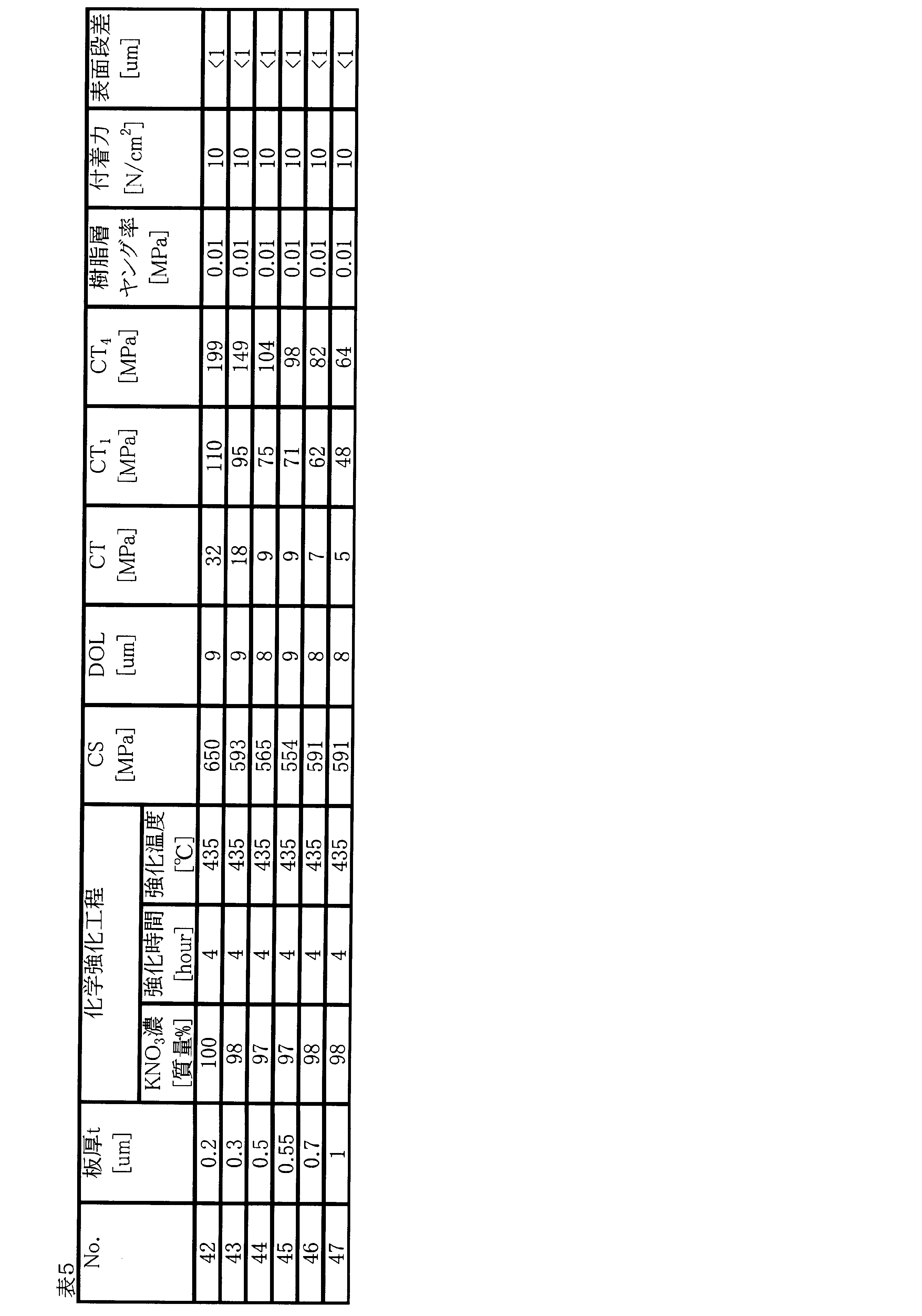
- Examples 42 to 47 First, 50 mm ⁇ 50 mm ⁇ 0.2 to 1.0 mm soda lime glass was obtained. Next, potassium nitrate (KNO 3 ) and sodium nitrate (NaNO 3 ) are added to a SUS cup with a total amount of 3500 g, and the concentration (mass%) of KNO 3 is shown in the section of chemical strengthening step in Table 5, respectively. It added so that it might pass, and it heated to the predetermined temperature with the mantle heater, and prepared the mixed molten salt of potassium nitrate and sodium nitrate.
- KNO 3 potassium nitrate
- NaNO 3 sodium nitrate
- Soda lime glass composition (in mol%): SiO 2 71%, Al 2 O 3 1%, Na 2 O 12%, K 2 O 1%, MgO 6%, CaO 9% Resin layers having Young's modulus and adhesion shown in Table 5 were laminated on the plate-like glasses of Examples 42 to 47, respectively, to obtain glass resin laminates of Examples 42 to 47.
- the plate thickness t (mm), CS value (MPa), DOL value ( ⁇ m), and CT value (MPa) are shown.
- the plate glass and the resin may be broken depending on how the plate glass is broken.
- it can be used as a protective plate for electronic equipment while maintaining a bonded state with its layer, and its CT value is the upper limit at which glass starts to scatter finely when it is broken by the evaluation of a conventional sheet glass. It is very different from the CT 1 value that was considered.
- the internal tensile stress CT of the sheet glass is different from the CT 1 value obtained by the above-described formula (5) [CT> ⁇ 38.7 ⁇ ln (t) +48.2]. It was found that when the critical value is exceeded, the surface step becomes large when it breaks. The numerical value corresponding to this critical value can be approximated by a curve.
- the value of the right side of the equation (4) was determined from the sheet thickness t [mm] shown in Tables 2 to 5, and the curve obtained by the approximation is shown in FIG.
- the internal tensile stress CT satisfies the above formula (4) [CT ⁇ 64.1 ⁇ t ⁇ 0.703 ] and the above formula (5) [CT> ⁇ 38.7 ⁇ ln (t) +48.2]. Accordingly, the surface level difference is small even after the glass is broken, and the user can use it temporarily with good operability even after the glass is broken.
- This condition was determined by the inventors of the present application as a result of an intensive study of the internal tensile stress CT of the sheet glass when the resin layer is interposed between the sheet glass and the electronic device housing (or display member). This is the upper limit.
- the internal tensile stress CT falls within the numerical range satisfying the expressions (4) and (5).
- the cracking behavior of the sheet glass can be managed.
Landscapes
- Chemical & Material Sciences (AREA)
- Life Sciences & Earth Sciences (AREA)
- Engineering & Computer Science (AREA)
- Chemical Kinetics & Catalysis (AREA)
- General Chemical & Material Sciences (AREA)
- Geochemistry & Mineralogy (AREA)
- Materials Engineering (AREA)
- Organic Chemistry (AREA)
- Surface Treatment Of Glass (AREA)
- Laminated Bodies (AREA)
- Devices For Indicating Variable Information By Combining Individual Elements (AREA)
Abstract
本発明は、主面に圧縮応力層が形成された板状ガラス、および前記板状ガラス上に設けられる樹脂層を含むガラス樹脂積層体であって、前記板状ガラスの主面における表面圧縮応力が200MPa以上でかつ前記圧縮応力層の深さが3μm以上であり、前記板状ガラスの内部引張応力CT(MPa)と板厚t(mm)が、下記の式(4)および式(5)を満たす、ガラス樹脂積層体に関する。 CT≦64.1×t-0.703 (4) CT>-38.7×ln(t)+48.2 (5)
Description
本発明は、ガラス樹脂積層体に関する。
スマートフォンや電子ペーパーに代表される電子機器や、自動車や電車の内部に設けられる車載用表示部材、太陽電池モジュール、照明等の多岐の用途において、カバー部材として所謂化学強化ガラスが使用されている。近年はガラスが用いられる機器等を軽量化することを目的とし、ガラスの厚みが薄くなってきている。
特許文献1には、ガラス内部の中央張力CTを、圧縮応力CSおよび外側領域の層の深さDOLにより『CT=CS×DOL/(t-2×DOL)』(式(1))と定義した上で、CTの値をある数値範囲とすることで強化ガラスの脆弱性を管理する方法が開示されている。この方法では、板厚t=0.3~1.5mmのアルミノシリケートガラスの実施例を元に、非直線的限界中央張力CT1(単位はMPa)と呼ばれる厚さの関数を、『CT1=-38.7×ln(t)+48.2』(式(2))と定義している。このCT1の値を中央張力CTの値の上限として提案しており、許容できない脆弱性の始まりの臨界値としている。板厚の薄いガラス板が使用される特定の用途においては、設計柔軟性が式(2)に基づいて制限されるとされている。
従来、強化ガラスの強度を高めるために、表面圧縮応力(CS)や圧縮応力層の深さ(DOL)の値を大きくすることが試みられてきた。しかしながら、式(1)に示す通り、CSまたはDOLの値を大きくすることで内部引張応力(CT)も大きくなり、その値は式(2)に示す上限により制限されていた。したがって、従来、CSおよびDOLの上限も実質的に制限されていた。
ここで、カバーガラス等に用いられる強化ガラスの割れ挙動を管理するための式(2)は、特許文献1に記載されている通り、カバーガラス単体に対する割れ試験の評価に基づいていた。したがって、カバーガラスと電子機器の筐体が一体化した状態における割れ挙動については検討されてこなかった。
そこで、本発明は、カバーガラスのCSおよびDOLを従来より高い値に設定可能であり、なおかつ割れた後もユーザーが一時的に操作性良く使用可能なガラス樹脂積層体を提供することを目的とする。
すなわち、本発明は、以下のガラス樹脂積層体を提供する。
〔1〕主面に圧縮応力層が形成された板状ガラス、および前記板状ガラス上に設けられる樹脂層を含むガラス樹脂積層体であって、前記板状ガラスの主面における表面圧縮応力が200MPa以上でかつ前記圧縮応力層の深さが3μm以上であり、前記板状ガラスの内部引張応力CT(MPa)と板厚t(mm)が、下記の式(4)および式(5)を満たす、ガラス樹脂積層体。
CT≦64.1×t-0.703 (4)
CT>-38.7×ln(t)+48.2 (5)
〔2〕前記樹脂層のヤング率が0.01~10MPaである〔1〕に記載のガラス樹脂積層体。
〔3〕前記板状ガラスに対する前記樹脂層の付着力が10~1000N/m2である〔1〕または〔2〕に記載のガラス樹脂積層体。
〔4〕前記板状ガラスの操作性インデックスが2以上である〔1〕~〔3〕のいずれか1に記載のガラス樹脂積層体。
〔5〕液晶表示装置を含む電子機器に用いられ、前記板状ガラスと前記液晶表示装置との間に、前記樹脂層が介在するように配置されて用いられる、〔1〕~〔4〕のいずれか1に記載のガラス樹脂積層体。
〔1〕主面に圧縮応力層が形成された板状ガラス、および前記板状ガラス上に設けられる樹脂層を含むガラス樹脂積層体であって、前記板状ガラスの主面における表面圧縮応力が200MPa以上でかつ前記圧縮応力層の深さが3μm以上であり、前記板状ガラスの内部引張応力CT(MPa)と板厚t(mm)が、下記の式(4)および式(5)を満たす、ガラス樹脂積層体。
CT≦64.1×t-0.703 (4)
CT>-38.7×ln(t)+48.2 (5)
〔2〕前記樹脂層のヤング率が0.01~10MPaである〔1〕に記載のガラス樹脂積層体。
〔3〕前記板状ガラスに対する前記樹脂層の付着力が10~1000N/m2である〔1〕または〔2〕に記載のガラス樹脂積層体。
〔4〕前記板状ガラスの操作性インデックスが2以上である〔1〕~〔3〕のいずれか1に記載のガラス樹脂積層体。
〔5〕液晶表示装置を含む電子機器に用いられ、前記板状ガラスと前記液晶表示装置との間に、前記樹脂層が介在するように配置されて用いられる、〔1〕~〔4〕のいずれか1に記載のガラス樹脂積層体。
開示の技術によれば、カバーガラスのCSおよびDOLを従来より高い値に設定可能であり、なおかつ割れた後もユーザーが操作性良く使用可能なガラス樹脂積層体を提供できる。
以下、図面を参照して発明を実施するための形態について説明する。各図面において、同一構成部分には同一符号を付し、重複した説明を省略する場合がある。
また、本明細書において“質量%”と“重量%”とは同義である。
また、本明細書において“質量%”と“重量%”とは同義である。
本実施の形態に係るガラス樹脂積層体においては、板状ガラス10は樹脂層20を介して電子機器筐体40の上に配置される。(詳細は後述する。)
このように、カバーガラスと電子機器筐体(特に液晶表示部材)との間に樹脂層が介在する構成の場合には、カバーガラスの割れ挙動が異なることを、本願発明者は鋭意検討の結果見出した。例えば、図1に示すような板状ガラス単体と、図2に示すようなカバーガラスと電子機器の筐体との間に樹脂が介在する構成では、板状ガラスの割れ挙動やその飛散の程度が大きく異なっていた。そして、カバーガラスと電子機器の筐体との間に樹脂が介在する構成の場合には、式(2)に示す上限は存在せず、CSおよびDOLを従来よりも高い値に設定できることを見出した(着目点1)。
また、カバーガラスと電子機器の筐体との間に樹脂が介在する構成では、カバーガラスが割れた後においても、その割れ方によってはカバーガラスと樹脂とは接着された状態を維持し、電子機器の保護板として使用可能な場合があることも見出した。そして、このような状態で使用する際には、カバーガラス表面に亀裂に起因する段差(凹凸)が生まれるが、亀裂の段差においてユーザーの操作性が変わるという新たな問題が生じる。このような操作性の問題を、カバーガラスの化学強化特性、すなわち応力プロファイルを制御することで解決可能なことを、本願発明者は見出した(着目点2)。
そこで、本実施形態では上記着目点1、2を鑑みた上で、カバーガラスのCSおよびDOLを従来より高い値に設定可能であり、なおかつ割れた後もユーザーが一時的に操作性良く使用可能なガラス樹脂積層体を提供する。
このように、カバーガラスと電子機器筐体(特に液晶表示部材)との間に樹脂層が介在する構成の場合には、カバーガラスの割れ挙動が異なることを、本願発明者は鋭意検討の結果見出した。例えば、図1に示すような板状ガラス単体と、図2に示すようなカバーガラスと電子機器の筐体との間に樹脂が介在する構成では、板状ガラスの割れ挙動やその飛散の程度が大きく異なっていた。そして、カバーガラスと電子機器の筐体との間に樹脂が介在する構成の場合には、式(2)に示す上限は存在せず、CSおよびDOLを従来よりも高い値に設定できることを見出した(着目点1)。
また、カバーガラスと電子機器の筐体との間に樹脂が介在する構成では、カバーガラスが割れた後においても、その割れ方によってはカバーガラスと樹脂とは接着された状態を維持し、電子機器の保護板として使用可能な場合があることも見出した。そして、このような状態で使用する際には、カバーガラス表面に亀裂に起因する段差(凹凸)が生まれるが、亀裂の段差においてユーザーの操作性が変わるという新たな問題が生じる。このような操作性の問題を、カバーガラスの化学強化特性、すなわち応力プロファイルを制御することで解決可能なことを、本願発明者は見出した(着目点2)。
そこで、本実施形態では上記着目点1、2を鑑みた上で、カバーガラスのCSおよびDOLを従来より高い値に設定可能であり、なおかつ割れた後もユーザーが一時的に操作性良く使用可能なガラス樹脂積層体を提供する。
(板状ガラスの形状および物性)
本実施の形態に係る板状ガラスは、通常、板形状をしているが、平板でも曲げ加工を施したガラス板でもよい。本実施の形態に係る板状ガラスの製造方法は特に限定されず、フロート法、フュージョン法、スロットダウンドロー法等、既知のガラス成形方法によって平板形状に成形されたガラス板であり、所望のガラス原料を連続溶融炉に投入し、ガラス原料を好ましくは1500~1600℃で加熱溶融し、清澄した後、成形装置に供給した上で溶融ガラスを板状に成形し、徐冷することにより製造することができる。板状ガラスは、130dPa・s以上の液相粘度を有することが好ましい。
本実施の形態に係る板状ガラスは、通常、板形状をしているが、平板でも曲げ加工を施したガラス板でもよい。本実施の形態に係る板状ガラスの製造方法は特に限定されず、フロート法、フュージョン法、スロットダウンドロー法等、既知のガラス成形方法によって平板形状に成形されたガラス板であり、所望のガラス原料を連続溶融炉に投入し、ガラス原料を好ましくは1500~1600℃で加熱溶融し、清澄した後、成形装置に供給した上で溶融ガラスを板状に成形し、徐冷することにより製造することができる。板状ガラスは、130dPa・s以上の液相粘度を有することが好ましい。
本実施の形態に係る板状ガラスは、既存の成形法で成形可能な寸法を有する。すなわち、フロート法で成形すれば、フロート成形幅の連続したリボン状のガラスが得られる。又、本実施の形態に係る板状ガラスは、最終的には使用目的に適した大きさに切断される。
本実施の形態に係る板状ガラスの板厚tは、軽量化に寄与するため2.0mm以下である。板厚の薄いガラスほど、内部引張応力CTを従来より高い値まで上げても操作性が悪化しなくなる。板厚tは好ましくは1.5mm以下、より好ましくは1.0mm以下、さらに好ましくは0.7mm以下、よりさらに好ましくは0.5mm以下、特に好ましくは0.3mm以下、最も好ましくは0.2mm以下である。
また、本実施の形態に係る板状ガラスの板厚tは、圧縮応力層をある程度深く設けるためにも0.05mm以上であることが好ましい。板厚tが0.05mm以上である板状ガラスであれば、化学強化処理によって少なくともDOLを3μm以上とすることができる。板厚tはより好ましくは0.07mm以上、さらに好ましくは0.1mm以上である。より大きなDOLを得るためには、板厚tを0.1mm以上とすることが好ましい。これにより、ガラスが大きく曲げられたときに端面から割れることを防ぐことができる。
本実施の形態に係る板状ガラスは、タブレットPC、ノートPC、スマートフォン及び電子書籍リーダー等の情報機器に備えられたタッチパネルディスプレイのカバーガラス及びタッチセンサーガラス、液晶テレビ及びPCモニタ等のカバーガラス、自動車インパネ等のカバーガラス、太陽電池用カバーガラス、建材の内装材、並びにビルや住宅の窓に用いられる複層ガラス等に用いることができる。すなわち、タブレットPC又はスマートフォン等のディスプレイの大きさであったり、太陽電池用カバーガラスであったり、それぞれの用途に応じた大きさとなる。
本実施の形態に係る板状ガラスは、一般的には矩形に切断されているが、円形又は多角形等の他の形状でも問題なく、穴あけ加工を施したガラスも含まれる。
本実施の形態に係る板状ガラスは、化学強化処理によってガラス表層に圧縮応力層を備える化学強化ガラスである。板状ガラスの表面圧縮応力(CS)は200MPa以上であることが好ましく、300MPa以上、400MPa以上、500MPa以上、600MPa以上、700MPa以上、800MPa以上、900MPa以上、1000MPa以上であることがより好ましい。CSが200MPa以上であることで、ガラス表面に傷が発生しにくくなる。
又、板状ガラスの使用時に圧縮応力層の深さ(DOL)の値を超える深さの傷がつくと板状ガラスの破壊につながるため、板状ガラスのDOLは深い方が好ましい。DOLは3μm以上であることが好ましく、4μm以上、5μm以上、6μm以上、7μm以上、8μm以上、9μm以上、10μm以上、12μm以上、15μm以上、20μm以上であることがより好ましい。
本実施の形態に係る板状ガラスの内部引張応力CT(以下、単に内部引張応力CT)は、『CT=CS×DOL/(t-2×DOL)』(式(1))もしくは、下記の式(3)により算出できる。ここで、tは板状ガラスの板厚(μm)、DOLは圧縮応力層の深さ(μm)、CSは表面圧縮応力値(MPa)、CS(x)とは、板状ガラスの深さ方向の位置xにおける圧縮応力値(MPa)、すなわち応力プロファイルである。また、CTの単位は(MPa)である。

式(1)は、ガラス内部の応力プロファイルの1次関数への近似(以下、三角形近似ともいう)が比較的許容できるような、所謂相補誤差関数プロファイルを有する化学強化ガラスに適用するCTの算出式である。相補誤差関数プロファイルを有する化学強化ガラスにおいては、式(1)と式(3)で得られるCTの値の誤差は小さく、式(1)で得られるCTの値の±5%の範囲内に式(3)のCTの値が入る。このような相補誤差関数プロファイルを有する化学強化ガラスにおいては、式(1)によりCTの値を求める。
一方、式(1)と式(3)で得られるCTの値の誤差は大きく、式(1)で得られるCTの値の±5%の範囲内に式(3)のCTの値が入らないような化学強化ガラスを、非相補誤差関数プロファイルを有する化学強化ガラスと呼ぶ。非相補誤差関数プロファイルを有する化学強化ガラスにおいては、式(3)によりCTの値を求める。
CSおよびDOLはガラス表面応力計(折原製作所社製 FSM-6000LE)を用いて測定できる。また、CS(x)はガラス表面応力計(折原製作所社製 FSM-6000LE/IR)を用いて測定できる。
本実施の形態に係る板状ガラスの内部引張応力CTは、『CT≦64.1×t-0.703』(式(4))を満たすことにより、板状ガラスの表面に亀裂が生じた場合でもガラス片が小さくなりすぎず樹脂層と接着されるため、亀裂に起因する表面段差(凹凸)が生まれにくくなっている。ここで、tは板状ガラスの板厚(mm)であり、式(4)の右辺は、本願の発明者が鋭意検討の結果見出した、板状ガラスの内部引張応力CTの上限値である。樹脂層と積層されるような本実施形態の板状ガラスにおいては、式(4)を満たす数値範囲内に内部引張応力CTを制御することで、板状ガラスの表面に亀裂が生じた場合の表面段差(凹凸)を管理できる。式(4)の右辺の根拠については後述する。
本実施の形態に係る板状ガラスの内部引張応力CTは、CSやDOLをより好ましい値に近付けるためにも、30MPa以上であることが好ましく、50MPa以上、70MPa以上、100MPa以上、120MPa以上、150MPa以上、200MPa以上であることがより好ましい。また、好適にCSやDOLを高めるために従来とは異なる材料設計を可能とするためにも、内部引張応力CTを式(2)により定められるCT1値より大きくする、すなわち『CT>-38.7×ln(t)+48.2』(式(5))を満たす。
(操作性インデックス)
板状ガラスの表面に亀裂が生じた場合のガラス樹脂積層体の操作性は、次の操作性インデックス(Safety index)により評価できる。操作性インデックスは、ビッカース圧子 (対面角136度のダイヤモンド正四角錘圧子)に10gの錘を付けた状態で、板状ガラスの表面に対して30mmの高さからビッカース圧子を自由落下させ、約0.8m/秒の速度でビッカース圧子を板状ガラスの表面側に衝突させて、板状ガラスを破壊させたときの表面段差(凹凸)によって表1のように3段階に分けられる。なお、破壊後の表面段差(凹凸)は表面粗さ・輪郭形状測定機(東京精密社製 Surfcom 1400D)により測定する。
板状ガラスの表面に亀裂が生じた場合のガラス樹脂積層体の操作性は、次の操作性インデックス(Safety index)により評価できる。操作性インデックスは、ビッカース圧子 (対面角136度のダイヤモンド正四角錘圧子)に10gの錘を付けた状態で、板状ガラスの表面に対して30mmの高さからビッカース圧子を自由落下させ、約0.8m/秒の速度でビッカース圧子を板状ガラスの表面側に衝突させて、板状ガラスを破壊させたときの表面段差(凹凸)によって表1のように3段階に分けられる。なお、破壊後の表面段差(凹凸)は表面粗さ・輪郭形状測定機(東京精密社製 Surfcom 1400D)により測定する。
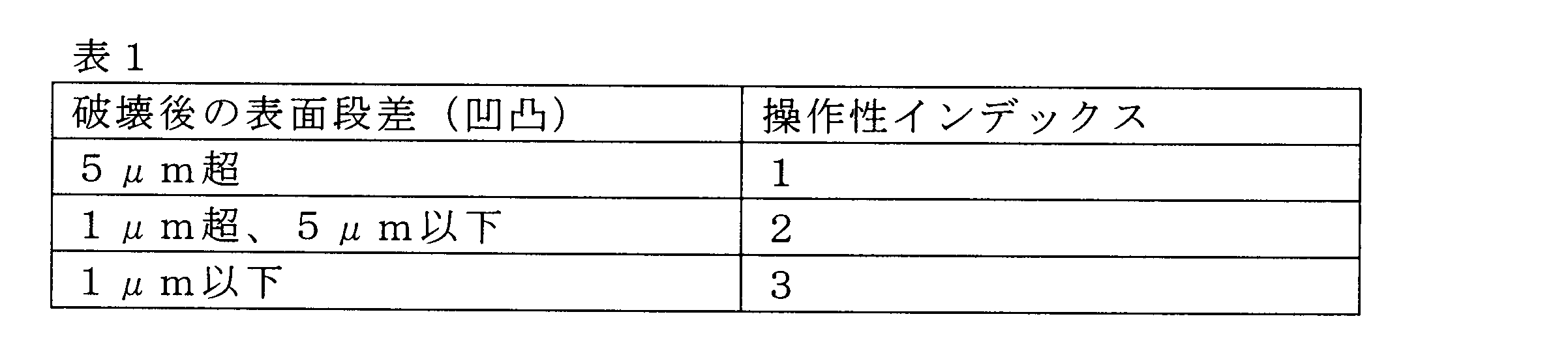
操作性インデックスが2以上である場合、板状ガラスが割れた後もユーザーが操作性良く使用可能なガラス樹脂積層体とすることができるため好ましい。操作性インデックスが3であれば、板状ガラスの亀裂をユーザーが指で確認できなくなり、操作性良く使用可能なガラス樹脂積層体とすることができるためより好ましい。
(化学強化用ガラス)
本実施形態の化学強化ガラスを製造するために使用される板状ガラスの組成について、特に断らない限りモル%表示含有量を用いて説明する。
本実施形態の化学強化ガラスを製造するために使用される板状ガラスの組成について、特に断らない限りモル%表示含有量を用いて説明する。
SiO2は、ガラス微細構造の中で網目構造を形成する成分として知られている。SiO2の含有量は、好ましくは60%以上であり、より好ましくは61%以上、62%以上、63%以上、64%以上、65%以上、66%以上、67%以上である。また、SiO2の含有量は、好ましくは72%以下であり、より好ましくは71%以下、70%以下、69%以下である。SiO2の含有量が60%以上であるとガラスとしての安定性や耐候性の点で優位である。一方、SiO2の含有量が72%以下であると熔解性および成形性の点で優位である。
Al2O3は化学強化における化学強化特性を向上させる作用があり、特にCSを向上する作用が大きい。ガラスの耐候性を向上する成分としても知られている。また、フロート成形時にボトム面からの錫の浸入を抑制する作用がある。さらに、SO2処理を行った際に脱アルカリを促進させる作用がある。Al2O3の含有量は、好ましくは1%以上であり、より好ましくは3%以上、5%以上、7%以上、9%以上、さらに好ましくは10%以上である。また、Al2O3の含有量は、好ましくは30%以下であり、より好ましくは20%以下、18%以下、16%以下、15%以下、14%以下である。Al2O3の含有量が1%以上であると、イオン交換により、所望のCS値が得られ、また、錫の浸入を抑制する効果、水分量変化に対する安定性の効果、脱アルカリ促進効果が得られる。一方、Al2O3の含有量が30%以下であると、DOL値が大きくなりすぎずCT値を一定値以下に抑制できる点で優位である。
MgOは、ガラスを安定化させる成分である。MgOの含有量は、好ましくは1%以上、より好ましくは2%以上、3%以上、4%以上である。また、MgOの含有量は、好ましくは12%以下であり、より好ましくは11%以下、10%以下、9%以下、8%以下、7%以下である。MgOの含有量が1%以上であると、高温での熔解性が良好になり、失透が起こり難くなる。一方、MgOの含有量が11%以下であると、失透の起こりにくさが維持され、充分なイオン交換速度が得られる。
CaOは、ガラスを安定化させる成分である。CaOは含有しなくとも良いが、含有する場合、その含有量は好ましくは3%以上であり、より好ましくは4%以上、5%以上、5%超、6%以上、7%以上である。また、CaOの含有量は、好ましくは10%以下であり、より好ましくは9%以下、8%以下である。特にCaOの含有量が5%超であると、DOL値が大きくなりすぎずCT値を一定値以下に抑制できる。一方、CaOの含有量が9%以下であると、充分なイオン交換速度が得られ、所望のDOL値が得られる。
Na2Oはイオン交換により圧縮応力層を形成させる成分であり、DOLを深くする作用がある。またガラスの高温粘性と失透温度を下げ、ガラスの熔解性、成形性を向上させる成分である。Na2Oは非架橋酸素(NBO;Non・bridge・oxygen)を生み出す成分であり、ガラス中の水分量が変化したときの化学強化特性の変動が少なくなる。Na2Oの含有量は、好ましくは10%以上であり、より好ましくは11%以上、12%以上、13%以上である。また、Na2Oの含有量は、好ましくは18%以下であり、より好ましくは17%以下、16%以下である。Na2Oの含有量が10%以上であると、イオン交換により所望の圧縮応力層を形成することができ、水分量変化に対する変動も抑えられる。一方、Na2Oの含有量が18%以下であると、充分な耐候性が得られ、フロート成形時にボトム面からの錫の浸入量も抑制でき、化学強化処理後にガラスを反り難くすることができる。
SiO2、Al2O3、MgOおよびNa2Oの含有量の合計は95%以上であることが好ましい。当該合計が95%以上であればクラック耐性を維持しつつ所望の圧縮応力層を得ることができる。より好ましくは96%以上、97%以上、98%以上、98.5%以上、99%以上である。
K2Oはイオン交換速度を増大しDOLを深くする効果があり、非架橋酸素を増大させる成分であるため、K2Oを含有する場合は5%以下が好ましく、より好ましくは4%以下、3%以下、2%以下、1%以下、0.8%以下、0.6%以下である。特に1%以下であるとDOLが深くなり過ぎず、また充分なCSが得られる。また、少量のK2Oは、フロート成形時にボトム面からの錫の浸入を抑える効果があるため、フロート成形する際には含有することが好ましい。この場合、K2Oの含有量は0.05%以上が好ましく、より好ましくは0.1%以上である。
Al2O3はCSを向上させる作用があるのに対し、Na2OはDOLを深くすると同時にCSを低下させる作用がある。また、K2Oはイオン交換速度を増大しDOLを深くする作用がある。したがって、Al2O3、Na2O、K2Oを特定の比率で含有することにより、CSの値を向上して化学強化処理後に切断することが可能となる。(Na2O+K2O)/Al2O3の比率は好ましくは8以下であり、より好ましくは7以下、6以下、5以下である。
Al2O3は高温粘性と失透温度を上げる成分であり、Na2OとK2Oは両者を下げる成分である。(Na2O+K2O)/Al2O3が1.8以上であれば、高温粘性が低くなり、失透温度も低くなる。また、DOLを十分な深さとすることができる。また、Al2O3は非架橋酸素を減少させる成分であるが、Na2OとK2Oは増加させる成分である。ガラスを安定的に生産し、かつ強度向上に必要なDOLを維持し、水分量変化に対して安定した化学強化特性を得るために、(Na2O+K2O)/Al2O3の比率は1.8以上であることが好ましく、より好ましくは2以上、3以上、4以上である。
また、同じ母組成で水分量が異なるガラスを化学強化処理した場合、CSの値が水分量の増加とともに低下し、DOLの値は水分量の増加で僅かに低下する程度で大きくは依存しない。さらに、ガラス中のNa2O、もしくはK2Oの含有量が増えると水分量が変化した時のCSの変化が小さくなる。これは、ガラス中の非架橋酸素が増加したためと考えられる。一方、Al2O3の含有量が増加するとガラス中の非架橋酸素は減少する。Al2O3を1%以上含有するガラスで、水分量によらずに安定した化学強化特性を得るためには、(Na2O+K2O)/Al2O3の比率が1.8以上であることが好ましい。
フロート法で成形されたガラスにおいては、ガラス中のAl2O3の含有量は錫の浸入に影響し、Al2O3成分が増えると錫浸入を抑制する作用がある。同時に、アルカリ成分すなわちNa2Oの含有量も錫浸入に影響し、アルカリ成分は錫浸入を増長する作用がある。したがって、Na2O/Al2O3の値を適正な範囲に保つことにより、フロート法成形での錫浸入を抑制し、化学強化後のガラスの反りを低減することが可能となる。
Al2O3とNa2Oの2成分に注目すると、CSおよびDOL、高温粘性、失透温度並びにボトム面からの錫の浸入量について互いに相反する作用がある。Al2O3とNa2Oは特定の比率で含有することが好ましく、CSの値を向上させ、および錫浸入量を低減させるために、Na2O/Al2O3が7以下であることが好ましく、より好ましくは6以下、さらに好ましくは5以下である。一方、強度向上に必要なDOLを維持し、高温粘性と失透温度の上昇を抑制するために、Na2O/Al2O3が1.5以上であることが好ましく、より好ましくは2以上、3以上、4以上である。
TiO2は天然原料中に多く存在し、黄色の着色源となることが知られている。TiO2の含有量は2%以下であり、好ましくは1%以下、より好ましくは0.5%以下である。TiO2の含有量が2%以下であればガラスが黄色味を帯びにくい。
Fe2O3は、自然界および生産ラインのあらゆるところに存在するため、その含有量をゼロにすることが極めて困難な成分である。酸化状態にあるFe2O3が黄色の着色原因となり、還元状態にあるFeOが青色の着色原因となることが知られており、両者のバランスでガラスは緑色に着色することが知られている。本実施形態のガラスをディスプレイ、窓ガラス、太陽電池のカバーガラス等に用いる場合、着色が薄いことが好ましい。全鉄量(トータルFe)をFe2O3として換算し、その含有量が0.15%以下であることが好ましく、より好ましくは0.10%以下、さらに好ましくは0.05%以下である。
SO3はガラスの熔融の清澄剤である。通常、ガラス中の含有量は原料から投入される量の半分以下となる。ガラス中のSO3の含有量は、0.02%以上であり、好ましくは0.05%以上であり、より好ましくは0.1%以上である。また、SO3の含有量は、0.4%以下であり、好ましくは0.35%以下であり、より好ましくは0.3%以下である。SO3の含有量が0.02%以上であると、充分に清澄し泡欠点を抑制できる。一方、SO3の含有量が0.4%以下であると、ガラス中に発生する硫酸ナトリウムの欠点を抑制できる。
この他、ガラスの熔融の清澄剤として、塩化物、フッ化物などを適宜含有してもよい。ただし、タッチパネルなどディスプレイ装置の視認性を上げるため、可視域に吸収をもつFe2O3、NiO、Cr2O3など原料中の不純物として混入するような成分はできるだけ減らすことが好ましく、各々質量百分率表示で0.15%以下であることが好ましく、より好ましくは0.05%以下である。
本発明のガラスは本質的に以上で説明した成分からなるが、本発明の目的を損なわない範囲でその他の成分を含有してもよい。そのような成分を含有する場合、それら成分の含有量の合計は5%以下であることが好ましく、より好ましくは3%以下、典型的には1%以下である。以下、上記その他成分について例示的に説明する。
ZrO2は、一般に化学強化での圧縮応力を大きくする作用があることが知られている。しかし、少量のZrO2を含有してもコスト増加の割には、その効果は大きくない。したがって、コストが許す範囲で任意の割合のZrO2を含有することが出来る。含有する場合は、2%以下であることが好ましく、より好ましくは1%以下、0.5%以下である。
SrOおよびBaOは、ガラスの高温粘性を下げ、失透温度を下げる目的で少量を含有してもよい。SrOまたはBaOにはイオン交換速度を低下させる作用があるため、含有する場合は、SrOまたはBaOとして0.5%以下であることが好ましい。
ZnOは、ガラスの高温での熔融性を向上するために、たとえば2%まで含有してもよい。しかし、フロート法で製造する場合には、フロートバスで還元され製品欠点となるので0.1%未満であることが好ましく、実質的に含有しないことがより好ましい。なお、「実質的に含有しない」とは、製造工程における不可避的な不純物として含有する量以上には含有しないことを意味する。
B2O3は高温での熔融性またはガラス強度の向上のために、1%未満の範囲で含有してもよい。一般的には、Na2OまたはK2Oのアルカリ成分とB2O3を同時に含有すると揮散が激しくなり、煉瓦を著しく浸食するので、B2O3の含有量は0.5%未満であることが好ましく、0.1%未満であることが好ましく、実質的に含有しないことが好ましい。
Li2Oは歪点を低くして応力緩和を起こりやすくし、その結果安定した圧縮応力層を得られなくする成分であるので含有しないことが好ましく、含有する場合であってもその含有量は1%未満であることが好ましく、より好ましくは0.05%以下、特に好ましくは0.01%未満である。
本実施形態に係る化学強化ガラス(化学強化処理後の板状ガラス)の組成は、上記した化学強化用ガラスの組成と同一と考えてよい。後述の化学強化処理によりガラス表面のNaイオンと無機塩中のKイオンとがイオン交換されるが、全体の組成の変化としては無視できる。
(化学強化処理)
化学強化処理は、大きなイオン半径のアルカリ金属イオン(典型的には、Kイオン)を含むアルカリ金属塩(例えば、硝酸カリウム塩)の融液に、浸漬やその他の方法によって、板状ガラスを接触させることにより、板状ガラス中の小さなイオン半径の金属イオン(典型的には、Naイオン)が大きなイオン半径の金属イオンと置換されることによりおこなわれる。これにより、アルカリ金属イオンの占有面積の差により板状ガラス表層に圧縮応力を発生させ、圧縮応力層を形成する。
化学強化処理は、大きなイオン半径のアルカリ金属イオン(典型的には、Kイオン)を含むアルカリ金属塩(例えば、硝酸カリウム塩)の融液に、浸漬やその他の方法によって、板状ガラスを接触させることにより、板状ガラス中の小さなイオン半径の金属イオン(典型的には、Naイオン)が大きなイオン半径の金属イオンと置換されることによりおこなわれる。これにより、アルカリ金属イオンの占有面積の差により板状ガラス表層に圧縮応力を発生させ、圧縮応力層を形成する。
ガラスとアルカリ金属イオンを含む溶融塩とを接触させる処理温度及び処理時間は、ガラス及び溶融塩の組成に応じて適宜調整する。溶融塩の加熱温度は、通常350℃以上が好ましく、370℃以上がより好ましい。又、通常500℃以下が好ましく、450℃以下がより好ましい。溶融塩の加熱温度を350℃以上とすることにより、イオン交換速度が低下し化学強化が入りにくくなるのを防ぐ。又、500℃以下とすることにより溶融塩の分解・劣化を抑制することができる。
アルミノシリケートガラスを溶融塩に接触させる時間は、十分な圧縮応力を付与するためには、通常1時間以上が好ましく、2時間以上がより好ましい。ソーダライムガラスを溶融塩に接触させる時間は、より深い圧縮応力層を付与するため、3時間以上が好ましく、4時間以上、5時間以上、6時間以上がより好ましい。又、長時間のイオン交換では、生産性が落ちるとともに、緩和により圧縮応力値が低下するため、アルミノシリケートガラスの場合は72時間以下が好ましく、24時間以下、8時間以下がより好ましい。ソーダライムガラスの場合はイオン交換に要する時間が比較的長いため、300時間以下が好ましく、200時間以下、100時間以下がより好ましい。
化学強化処理を行うための溶融塩としては、例えば、硝酸カリウム塩、硫酸カリウム塩、炭酸カリウム塩及び塩化カリウム塩等のアルカリ硝酸塩、アルカリ硫酸塩及びアルカリ塩化物塩等が挙げられる。これらの溶融塩は単独で用いてもよいし、複数種を組み合わせて用いてもよい。又、化学強化特性を調整するために、ナトリウム(Naイオン)やリチウム(Liイオン)を含む塩を混ぜてもよい。
化学強化処理を行うための溶融塩は、少なくともカリウムイオン含む処理塩を用いることが好ましい。このような処理塩としては、例えば、硝酸カリウムを50質量%以上含有する塩が好適に挙げられる。又、混合溶融塩には、その他の成分を含有してもよい。その他の成分としては、例えば、硫酸ナトリウム及び硫酸カリウム等のアルカリ硫酸塩、並びに塩化ナトリウム及び塩化カリウム等のアルカリ塩化塩等が挙げられる。
本実施の形態に係る板状ガラスにおいて、化学強化処理の処理条件は、特に限定されず、ガラスの特性及び溶融塩等を考慮して最適な条件を選択できる。
また、化学強化処理は、連続的な工程、例えばガラス板製造工程において連続的に移動するガラスリボンに対してオンラインで順次行ってもよいし、又は非連続的にオンラインで行ってもよい。
(樹脂層)
樹脂層に含まれる樹脂としては、一般的に用いられている公知の粘着性組成物を使用することができる。例えば、アクリル樹脂、ウレタン樹脂、シリコーン樹脂、フェノール樹脂、エポキシ樹脂、メラミン樹脂、尿素樹脂、不飽和ポリエステル樹脂、アルキド樹脂、ポリイミド樹脂、フッ素樹脂などが挙げられる。粘着性組成物は、いくつかの種類のモノマーが重合した共重合体樹脂(コポリマー)でもよく、いくつかの種類の樹脂を混合してもよい。中でもアクリル樹脂や、シリコーン樹脂が、耐熱性や剥離性、透明性に優れるため好ましい。
樹脂層に含まれる樹脂としては、一般的に用いられている公知の粘着性組成物を使用することができる。例えば、アクリル樹脂、ウレタン樹脂、シリコーン樹脂、フェノール樹脂、エポキシ樹脂、メラミン樹脂、尿素樹脂、不飽和ポリエステル樹脂、アルキド樹脂、ポリイミド樹脂、フッ素樹脂などが挙げられる。粘着性組成物は、いくつかの種類のモノマーが重合した共重合体樹脂(コポリマー)でもよく、いくつかの種類の樹脂を混合してもよい。中でもアクリル樹脂や、シリコーン樹脂が、耐熱性や剥離性、透明性に優れるため好ましい。
樹脂層のヤング率は好ましくは0.01~10MPaである。これにより、亀裂が生じた板状ガラスを保持しつつ、破壊の衝撃を吸収して表面段差を小さくすることができる。樹脂層のヤング率はより好ましくは0.01~5MPaであり、さらに好ましくは0.01~1MPaである。
(ガラス樹脂積層体)
図3に本実施の形態に係るガラス樹脂積層体の構成の一例を示す。板状ガラス10は樹脂層20を介して電子機器筐体40の上に配置される。樹脂層20は板状ガラス10の全面を被覆するように配置されてもよいし、板状ガラス10の一部のみを被覆してもよい。また、樹脂層20は電子機器筐体40の中でも特にディスプレイ部材30に接着されることが、板状ガラス10の透明性を十分活かすことができるため好ましい。樹脂層20はディスプレイ部材30の全面を被覆してもよいし、一部のみを被覆してもよい。
図3に本実施の形態に係るガラス樹脂積層体の構成の一例を示す。板状ガラス10は樹脂層20を介して電子機器筐体40の上に配置される。樹脂層20は板状ガラス10の全面を被覆するように配置されてもよいし、板状ガラス10の一部のみを被覆してもよい。また、樹脂層20は電子機器筐体40の中でも特にディスプレイ部材30に接着されることが、板状ガラス10の透明性を十分活かすことができるため好ましい。樹脂層20はディスプレイ部材30の全面を被覆してもよいし、一部のみを被覆してもよい。
板状ガラス10に対する樹脂層20の付着力は好ましくは10~1000N/m2である。これにより、板状ガラス10が破壊され亀裂が生じた場合にも、ある程度以上の大きさのガラス片が樹脂層20と接着されることで、表面段差を小さくすることができる。付着力はより好ましくは30~750N/m2であり、さらに好ましくは50~500N/m2である。樹脂層20の付着力は、せん断接着強度(JIS K6850:1999)に準じて、測定した値である。
本実施の形態に係る板状ガラスおよびガラス樹脂積層体の用途は、特段限定されない。高い機械的強度を有することから、落下による衝撃や、他の物質との接触が予想される箇所への使用に好適である。例えば、本実施の形態に係る板状ガラスおよびガラス樹脂積層体は、タブレットPC、ノートPC、スマートフォン及び電子書籍リーダー等の情報機器に備えられたタッチパネルディスプレイのカバーガラス及びタッチセンサーガラス、液晶テレビ及びPCモニタ等のカバーガラス、自動車インパネ等のカバーガラス、太陽電池用カバーガラス、建材の内装材、並びにビルや住宅の窓に用いられる複層ガラス等に用いることができる。すなわち、タブレットPC又はスマートフォン等のディスプレイの大きさであったり、太陽電池用カバーガラスであったり、それぞれの用途に応じた大きさとなる。
本実施の形態に係るガラス樹脂積層体に対応する実施例を示す。
<評価方法>
本実施例における各種評価は以下に示す分析方法により行った。
本実施例における各種評価は以下に示す分析方法により行った。
(ガラスの評価:表面応力)
表面圧縮応力値(CS)及び圧縮応力層の深さ(DOL)及び内部引張応力(CT)は、ガラス表面応力計(折原製作所社製 FSM-6000LE)を用いて測定した。
表面圧縮応力値(CS)及び圧縮応力層の深さ(DOL)及び内部引張応力(CT)は、ガラス表面応力計(折原製作所社製 FSM-6000LE)を用いて測定した。
(ガラス樹脂積層体の評価:割れ挙動)
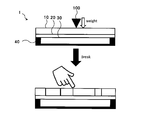
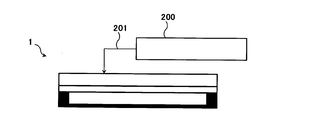
カバーガラスと電子機器の筐体(特に液晶表示部材)との貼り合わせた場合の、カバーガラスの割れ挙動は次のように評価した。図4~6に評価方法を概略図により示す。まず、所望の表面圧縮応力値(CS)及び圧縮応力層の深さ(DOL)及び内部引張応力(CT)を付与した板状ガラス10を、樹脂層20を介して、電子機器筐体40と貼り合わせてガラス樹脂積層体1を作製する。次に、圧子に10gの錘を付けた状態で30mmの高さから圧子を自由落下させ、約0.8m/秒の速度で圧子をガラスに衝突させることで、ガラスを破壊させる(図4,5)。続いて、板状ガラス10の表面段差を、表面粗さ・輪郭形状測定機200(東京精密社製 Surfcom 1400D)を用いて評価した(図6)。なお、ここでいう板状ガラス10の表面段差とは、破壊後のガラスの断片と断片との高さの差の最大値として測定される。
カバーガラスと電子機器の筐体(特に液晶表示部材)との貼り合わせた場合の、カバーガラスの割れ挙動は次のように評価した。図4~6に評価方法を概略図により示す。まず、所望の表面圧縮応力値(CS)及び圧縮応力層の深さ(DOL)及び内部引張応力(CT)を付与した板状ガラス10を、樹脂層20を介して、電子機器筐体40と貼り合わせてガラス樹脂積層体1を作製する。次に、圧子に10gの錘を付けた状態で30mmの高さから圧子を自由落下させ、約0.8m/秒の速度で圧子をガラスに衝突させることで、ガラスを破壊させる(図4,5)。続いて、板状ガラス10の表面段差を、表面粗さ・輪郭形状測定機200(東京精密社製 Surfcom 1400D)を用いて評価した(図6)。なお、ここでいう板状ガラス10の表面段差とは、破壊後のガラスの断片と断片との高さの差の最大値として測定される。
<例1~13>
まず、以下の組成からなる50mm×50mm×0.2~1.0mmのアルミノシリケートガラスを得た。次に、SUS製のカップに硝酸カリウム(KNO3)と硝酸ナトリウム(NaNO3)を、その合計量が3500gとなり、かつKNO3の濃度(質量%)がそれぞれ表2の化学強化工程の項に示す通りとなるよう加え、マントルヒーターで所定の温度まで加熱して、硝酸カリウムと硝酸ナトリウムの混合溶融塩を調製した。ここに、先述のアルミノシリケートガラスを425℃まで予熱した後、溶融塩に所定の時間浸漬し、イオン交換処理した後、室温付近まで冷却することにより化学強化処理を行った。化学強化処理の条件は、表2に記載の通りである。得られた板状ガラスを純水で数回洗浄した後、エアブローにより乾燥した。以上より、例1~13の板状ガラスを得た。
アルミノシリケートガラス組成(モル%表示):SiO2 63%、Al2O3 8%、Na2O 13%、K2O 4%、MgO 11%、ZrO2 1%
例1~13の板状ガラスに対して、それぞれ表2に示すヤング率と付着力を有する樹脂層を積層し、例1~13のガラス樹脂積層体を得た。
まず、以下の組成からなる50mm×50mm×0.2~1.0mmのアルミノシリケートガラスを得た。次に、SUS製のカップに硝酸カリウム(KNO3)と硝酸ナトリウム(NaNO3)を、その合計量が3500gとなり、かつKNO3の濃度(質量%)がそれぞれ表2の化学強化工程の項に示す通りとなるよう加え、マントルヒーターで所定の温度まで加熱して、硝酸カリウムと硝酸ナトリウムの混合溶融塩を調製した。ここに、先述のアルミノシリケートガラスを425℃まで予熱した後、溶融塩に所定の時間浸漬し、イオン交換処理した後、室温付近まで冷却することにより化学強化処理を行った。化学強化処理の条件は、表2に記載の通りである。得られた板状ガラスを純水で数回洗浄した後、エアブローにより乾燥した。以上より、例1~13の板状ガラスを得た。
アルミノシリケートガラス組成(モル%表示):SiO2 63%、Al2O3 8%、Na2O 13%、K2O 4%、MgO 11%、ZrO2 1%
例1~13の板状ガラスに対して、それぞれ表2に示すヤング率と付着力を有する樹脂層を積層し、例1~13のガラス樹脂積層体を得た。
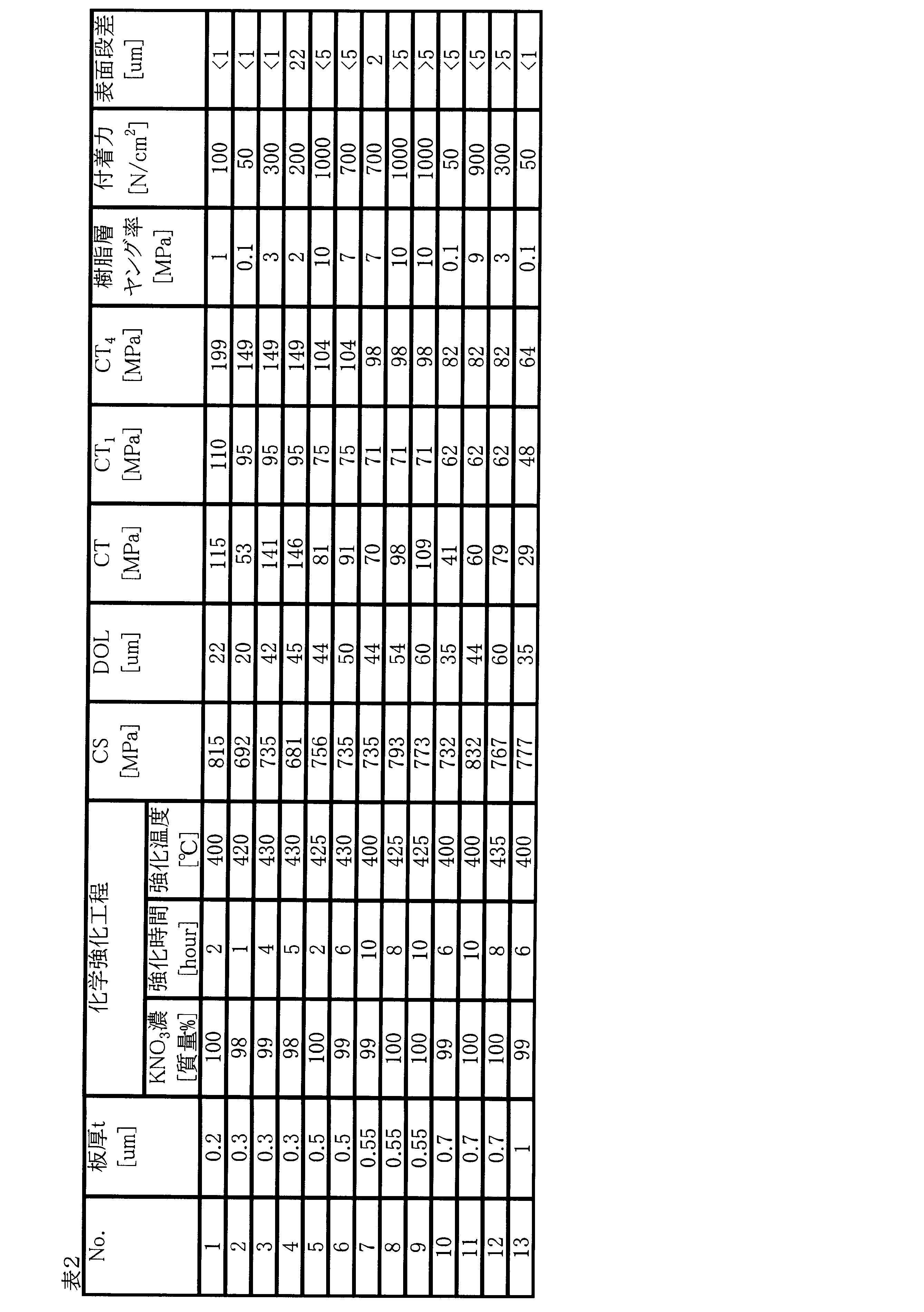
こうして得られたガラス樹脂積層体について各種評価を行った。板厚t(mm)、CS値(MPa)、DOL値(μm)、CT値(MPa)を示す。なお、いずれの板状ガラスも相補誤差関数プロファイルを有しており、CT値は式(1)により求めた。CT1値は、板厚t(mm)から、CT1=-38.7×ln(t)+48.2[MPa]として求めた。CT4値は、板厚t(mm)から、CT4=64.1×t-0.703[MPa]として求めた。結果を表2に示す。
<例14~30>
まず、50mm×50mm×0.2~1.0mmのアルミノシリケートガラスを得た。次に、SUS製のカップに硝酸カリウム(KNO3)と硝酸ナトリウム(NaNO3)を、その合計量が3500gとなり、かつKNO3の濃度(質量%)がそれぞれ表3の化学強化工程の項に示す通りとなるよう加え、マントルヒーターで所定の温度まで加熱して、硝酸カリウムと硝酸ナトリウムの混合溶融塩を調製した。ここに、先述のアルミノシリケートガラスを425℃まで予熱した後、溶融塩に所定の時間浸漬し、イオン交換処理した後、室温付近まで冷却することにより化学強化処理を行った。化学強化処理の条件は、表3に記載の通りである。得られた板状ガラスを純水で数回洗浄した後、エアブローにより乾燥した。以上より、例14~30の板状ガラスを得た。
アルミノシリケートガラス組成(モル%表示):SiO2 68%、Al2O3 10%、Na2O 14%、MgO 8%
例14~30の板状ガラスに対して、それぞれ表3に示すヤング率と付着力を有する樹脂層を積層し、例14~30のガラス樹脂積層体を得た。
まず、50mm×50mm×0.2~1.0mmのアルミノシリケートガラスを得た。次に、SUS製のカップに硝酸カリウム(KNO3)と硝酸ナトリウム(NaNO3)を、その合計量が3500gとなり、かつKNO3の濃度(質量%)がそれぞれ表3の化学強化工程の項に示す通りとなるよう加え、マントルヒーターで所定の温度まで加熱して、硝酸カリウムと硝酸ナトリウムの混合溶融塩を調製した。ここに、先述のアルミノシリケートガラスを425℃まで予熱した後、溶融塩に所定の時間浸漬し、イオン交換処理した後、室温付近まで冷却することにより化学強化処理を行った。化学強化処理の条件は、表3に記載の通りである。得られた板状ガラスを純水で数回洗浄した後、エアブローにより乾燥した。以上より、例14~30の板状ガラスを得た。
アルミノシリケートガラス組成(モル%表示):SiO2 68%、Al2O3 10%、Na2O 14%、MgO 8%
例14~30の板状ガラスに対して、それぞれ表3に示すヤング率と付着力を有する樹脂層を積層し、例14~30のガラス樹脂積層体を得た。
こうして得られたガラス樹脂積層体について各種評価を行った。板厚t(mm)、CS値(MPa)、DOL値(μm)、CT値(MPa)を示す。なお、いずれの板状ガラスも相補誤差関数プロファイルを有しており、CT値は式(1)により求めた。CT1値は、板厚t(mm)から、CT1=-38.7×ln(t)+48.2[MPa]として求めた。CT4値は、板厚t(mm)から、CT4=64.1×t-0.703[MPa]として求めた。結果を表3に示す。

<例31~41>
まず、50mm×50mm×0.2~1.0mmのアルミノボロシリケートガラスを得た。次に、SUS製のカップに硝酸カリウム(KNO3)と硝酸ナトリウム(NaNO3)を、その合計量が3500gとなり、かつKNO3の濃度(質量%)がそれぞれ表4の化学強化工程の項に示す通りとなるよう加え、マントルヒーターで所定の温度まで加熱して、硝酸カリウムと硝酸ナトリウムの混合溶融塩を調製した。ここに、先述のアルミノボロシリケートガラスを425℃まで予熱した後、溶融塩に所定の時間浸漬し、イオン交換処理した後、室温付近まで冷却することにより化学強化処理を行った。化学強化処理の条件は、表4に記載の通りである。得られた板状ガラスを純水で数回洗浄した後、エアブローにより乾燥した。以上より、例31~41の板状ガラスを得た。
アルミノボロシリケートガラス組成(モル%表示):SiO2 67%、B2O3 4%、Al2O3 13%、Na2O 14%、MgO 2%
例31~41の板状ガラスに対して、それぞれ表4に示すヤング率と付着力を有する樹脂層を積層し、例31~41のガラス樹脂積層体を得た。
まず、50mm×50mm×0.2~1.0mmのアルミノボロシリケートガラスを得た。次に、SUS製のカップに硝酸カリウム(KNO3)と硝酸ナトリウム(NaNO3)を、その合計量が3500gとなり、かつKNO3の濃度(質量%)がそれぞれ表4の化学強化工程の項に示す通りとなるよう加え、マントルヒーターで所定の温度まで加熱して、硝酸カリウムと硝酸ナトリウムの混合溶融塩を調製した。ここに、先述のアルミノボロシリケートガラスを425℃まで予熱した後、溶融塩に所定の時間浸漬し、イオン交換処理した後、室温付近まで冷却することにより化学強化処理を行った。化学強化処理の条件は、表4に記載の通りである。得られた板状ガラスを純水で数回洗浄した後、エアブローにより乾燥した。以上より、例31~41の板状ガラスを得た。
アルミノボロシリケートガラス組成(モル%表示):SiO2 67%、B2O3 4%、Al2O3 13%、Na2O 14%、MgO 2%
例31~41の板状ガラスに対して、それぞれ表4に示すヤング率と付着力を有する樹脂層を積層し、例31~41のガラス樹脂積層体を得た。
こうして得られたガラス樹脂積層体について各種評価を行った。板厚t(mm)、CS値(MPa)、DOL値(μm)、CT値(MPa)を示す。CT1値は、板厚t(mm)から、CT1=-38.7×ln(t)+48.2[MPa]として求めた。CT4値は、板厚t(mm)から、CT4=64.1×t-0.703[MPa]として求めた。結果を表4に示す。

<例42~47>
まず、50mm×50mm×0.2~1.0mmのソーダライムガラスを得た。次に、SUS製のカップに硝酸カリウム(KNO3)と硝酸ナトリウム(NaNO3)を、その合計量が3500gとなり、かつKNO3の濃度(質量%)がそれぞれ表5の化学強化工程の項に示す通りとなるよう加え、マントルヒーターで所定の温度まで加熱して、硝酸カリウムと硝酸ナトリウムの混合溶融塩を調製した。ここに、先述のソーダライムガラスを425℃まで予熱した後、溶融塩に所定の時間浸漬し、イオン交換処理した後、室温付近まで冷却することにより化学強化処理を行った。化学強化処理の条件は、表5に記載の通りである。得られた板状ガラスを純水で数回洗浄した後、エアブローにより乾燥した。以上より、例42~47の板状ガラスを得た。
ソーダライムガラス組成(モル%表示):SiO2 71%、Al2O3 1%、Na2O 12%、K2O 1%、MgO 6%、CaO 9%
例42~47の板状ガラスに対して、それぞれ表5に示すヤング率と付着力を有する樹脂層を積層し、例42~47のガラス樹脂積層体を得た。
まず、50mm×50mm×0.2~1.0mmのソーダライムガラスを得た。次に、SUS製のカップに硝酸カリウム(KNO3)と硝酸ナトリウム(NaNO3)を、その合計量が3500gとなり、かつKNO3の濃度(質量%)がそれぞれ表5の化学強化工程の項に示す通りとなるよう加え、マントルヒーターで所定の温度まで加熱して、硝酸カリウムと硝酸ナトリウムの混合溶融塩を調製した。ここに、先述のソーダライムガラスを425℃まで予熱した後、溶融塩に所定の時間浸漬し、イオン交換処理した後、室温付近まで冷却することにより化学強化処理を行った。化学強化処理の条件は、表5に記載の通りである。得られた板状ガラスを純水で数回洗浄した後、エアブローにより乾燥した。以上より、例42~47の板状ガラスを得た。
ソーダライムガラス組成(モル%表示):SiO2 71%、Al2O3 1%、Na2O 12%、K2O 1%、MgO 6%、CaO 9%
例42~47の板状ガラスに対して、それぞれ表5に示すヤング率と付着力を有する樹脂層を積層し、例42~47のガラス樹脂積層体を得た。
こうして得られたガラス樹脂積層体について各種評価を行った。板厚t(mm)、CS値(MPa)、DOL値(μm)、CT値(MPa)を示す。CT1値は、板厚t(mm)から、CT1=-38.7×ln(t)+48.2[MPa]として求めた。CT4値は、板厚t(mm)から、CT4=64.1×t-0.703[MPa]として求めた。結果を表5に示す。
また、表2~5の各試料について、板状ガラスの板厚と内部引張応力CT値の関係を図7にプロットした。また、CT1値に相当する曲線も示した。なお、図7において、破壊した際に表面段差が5μm以下であった試料を○でプロットし、5μm超であった試料を×でプロットした。
図7の結果から、CT値がCT1値を超えた板状ガラスでも、破壊した際に表面段差の小さいものがあることが分かった。これは、ヤング率の比較的低い樹脂層と板状ガラスが積層されることで、板状ガラスの破砕が抑制されたためであると考えられる。
したがって、板状ガラスと電子機器筐体(またはディスプレイ部材)との間に樹脂層が介在する構成の場合には、板状ガラスが割れた後においても、その割れ方によっては板状ガラスと樹脂層とは接着された状態を維持し、電子機器の保護板として使用可能な場合があり、そのCT値は、従来板状ガラス単体の評価により、ガラスが割れたときに細かく飛散し始める上限で考えられていたCT1値とは大きく異なる。
一方で、図7の結果から、板状ガラスの内部引張応力CTが前述の式(5)[CT>-38.7×ln(t)+48.2]で求められるCT1値とは異なるある臨界値を超えると、破壊した際に表面段差が大きくなることが分かった。この臨界値にあたる数値は曲線で近似することができる。板状ガラスの割れ挙動を管理できるよう、表2~5に示される板厚t[mm]により式(4)の右辺の値を求め、図7に前記近似により得られる曲線を示した。
表2~5および図7で示すように、板厚t[mm]の関数で64.1×t-0.703[MPa]を超える内部引張応力CTを有する板状ガラスでは、表面段差が大きかった。そこで、本明細書では内部引張応力CTの上限値をCT4=64.1×t-0.703[MPa]と定義した。
内部引張応力CTが、前述の式(4)[CT≦64.1×t-0.703]および前述の式(5)[CT>-38.7×ln(t)+48.2]を満たすことにより、ガラスが割れた後も表面段差が小さく、ガラスが割れた後もユーザーが一時的に操作性良く使用可能である。この条件は、本願発明者が鋭意検討の結果見出した、板状ガラスと電子機器筐体(またはディスプレイ部材)との間に樹脂層が介在する構成の場合の板状ガラスの内部引張応力CTの上限値である。
これらの結果より、板状ガラスと電子機器筐体(特にディスプレイ部材)との間に樹脂層が介在する構成の場合、式(4)および式(5)を満たす数値範囲内に内部引張応力CTを制御することで、板状ガラスの割れ挙動を管理できる。
以上、好ましい実施の形態及び実施例について詳説したが、上述した実施の形態及び実施例に制限されることはなく、特許請求の範囲に記載された範囲を逸脱することなく、上述した実施の形態及び実施例に種々の変形及び置換を加えることができる。又、上記の各実施の形態は、適宜組み合わせることができる。
本発明を詳細にまた特定の実施態様を参照して説明したが、本発明の精神と範囲を逸脱することなく様々な変更や修正を加えることができることは当業者にとって明らかである。本出願は2015年10月16日出願の日本特許出願(特願2015-204413)に基づくものであり、その内容はここに参照として取り込まれる。
1 ガラス樹脂積層体
10 板状ガラス
20 樹脂層
30 ディスプレイ部材
40 電子機器筐体
100 圧子
200 表面粗さ・輪郭形状測定器
201 探針
10 板状ガラス
20 樹脂層
30 ディスプレイ部材
40 電子機器筐体
100 圧子
200 表面粗さ・輪郭形状測定器
201 探針
Claims (5)
- 主面に圧縮応力層が形成された板状ガラス、および前記板状ガラス上に設けられる樹脂層を含むガラス樹脂積層体であって、
前記板状ガラスの主面における表面圧縮応力が200MPa以上でかつ前記圧縮応力層の深さが3μm以上であり、
前記板状ガラスの内部引張応力CT(MPa)と板厚t(mm)が、下記の式(4)および式(5)を満たす、ガラス樹脂積層体。
CT≦64.1×t-0.703 (4)
CT>-38.7×ln(t)+48.2 (5) - 前記樹脂層のヤング率が0.01~10MPaである請求項1に記載のガラス樹脂積層体。
- 前記板状ガラスに対する前記樹脂層の付着力が10~1000N/m2である請求項1または2に記載のガラス樹脂積層体。
- 前記板状ガラスの操作性インデックスが2以上である請求項1~3のいずれか1項に記載のガラス樹脂積層体。
- 液晶表示装置を含む電子機器に用いられ、
前記板状ガラスと前記液晶表示装置との間に、前記樹脂層が介在するように配置されて用いられる、請求項1~4のいずれか1項に記載のガラス樹脂積層体。
Priority Applications (3)
| Application Number | Priority Date | Filing Date | Title |
|---|---|---|---|
| JP2017545493A JPWO2017065286A1 (ja) | 2015-10-16 | 2016-10-14 | ガラス樹脂積層体 |
| CN201680062361.6A CN108349795B (zh) | 2015-10-16 | 2016-10-14 | 玻璃树脂层叠体 |
| US15/952,465 US20180230045A1 (en) | 2015-10-16 | 2018-04-13 | Glass resin laminate |
Applications Claiming Priority (2)
| Application Number | Priority Date | Filing Date | Title |
|---|---|---|---|
| JP2015204413 | 2015-10-16 | ||
| JP2015-204413 | 2015-10-16 |
Related Child Applications (1)
| Application Number | Title | Priority Date | Filing Date |
|---|---|---|---|
| US15/952,465 Continuation US20180230045A1 (en) | 2015-10-16 | 2018-04-13 | Glass resin laminate |
Publications (1)
| Publication Number | Publication Date |
|---|---|
| WO2017065286A1 true WO2017065286A1 (ja) | 2017-04-20 |
Family
ID=58518268
Family Applications (1)
| Application Number | Title | Priority Date | Filing Date |
|---|---|---|---|
| PCT/JP2016/080580 Ceased WO2017065286A1 (ja) | 2015-10-16 | 2016-10-14 | ガラス樹脂積層体 |
Country Status (4)
| Country | Link |
|---|---|
| US (1) | US20180230045A1 (ja) |
| JP (1) | JPWO2017065286A1 (ja) |
| CN (1) | CN108349795B (ja) |
| WO (1) | WO2017065286A1 (ja) |
Cited By (6)
| Publication number | Priority date | Publication date | Assignee | Title |
|---|---|---|---|---|
| JP2019534475A (ja) * | 2017-04-25 | 2019-11-28 | エルジー・ケム・リミテッド | 光学デバイス |
| WO2020023234A1 (en) * | 2018-07-23 | 2020-01-30 | Corning Incorporated | Automotive interiors and cover glass articles with improved headform impact performance and post-breakage visibility |
| KR20200014266A (ko) * | 2017-06-02 | 2020-02-10 | 쇼오트 글라스 테크놀로지스 (쑤저우) 코퍼레이션 리미티드. | 높은 접촉 저항성 가요성 초박형 유리 |
| WO2021261603A1 (ja) * | 2020-06-26 | 2021-12-30 | 日本板硝子株式会社 | 表示装置 |
| JP2024091434A (ja) * | 2022-12-23 | 2024-07-04 | 住友ゴム工業株式会社 | ポリマー被覆ガラス基材 |
| US12473455B2 (en) | 2022-03-31 | 2025-11-18 | Sumitomo Rubber Industries, Ltd. | Polymer-coated substrate and medical analysis device |
Families Citing this family (1)
| Publication number | Priority date | Publication date | Assignee | Title |
|---|---|---|---|---|
| WO2021042388A1 (en) * | 2019-09-06 | 2021-03-11 | Schott Glass Technologies (Suzhou) Co. Ltd. | Micro-optical element having high bonding strength between glass substrate and micro-structure layer |
Citations (11)
| Publication number | Priority date | Publication date | Assignee | Title |
|---|---|---|---|---|
| JP2005055641A (ja) * | 2003-08-04 | 2005-03-03 | Yokogawa Electric Corp | 液晶表示装置 |
| JP2009186959A (ja) * | 2007-04-10 | 2009-08-20 | Sony Chemical & Information Device Corp | 画像表示装置の製造方法 |
| JP2011195449A (ja) * | 2007-08-03 | 2011-10-06 | Nippon Electric Glass Co Ltd | 強化ガラス基板及びその製造方法 |
| JP2011213576A (ja) * | 2010-03-19 | 2011-10-27 | Ishizuka Glass Co Ltd | 化学強化用ガラス組成物及び化学強化ガラス材 |
| WO2013179882A1 (ja) * | 2012-05-28 | 2013-12-05 | 旭硝子株式会社 | 輸送機械用フラットパネルディスプレイ装置のカバーガラス、及び輸送機械用フラットパネルディスプレイ装置 |
| WO2014030738A1 (ja) * | 2012-08-23 | 2014-02-27 | Hoya株式会社 | 電子機器用カバーガラスのガラス基板及び電子機器用カバーガラス、並びに電子機器用カバーガラスのガラス基板の製造方法 |
| JP2014073960A (ja) * | 2010-09-30 | 2014-04-24 | Avanstrate Inc | カバーガラスの製造方法及びカバーガラス |
| JP2014218422A (ja) * | 2013-04-12 | 2014-11-20 | 旭硝子株式会社 | 防火ガラス、防火ガラスの評価方法及び防火ガラスの製造方法 |
| JP2015101502A (ja) * | 2013-11-22 | 2015-06-04 | 旭硝子株式会社 | 化学強化ガラス板 |
| JP2015523310A (ja) * | 2012-06-08 | 2015-08-13 | コーニング インコーポレイテッド | 強化ガラス物品と製造方法 |
| WO2016170931A1 (ja) * | 2015-04-23 | 2016-10-27 | 日本電気硝子株式会社 | 強化ガラス |
Family Cites Families (5)
| Publication number | Priority date | Publication date | Assignee | Title |
|---|---|---|---|---|
| JP4711354B2 (ja) * | 2007-07-17 | 2011-06-29 | ソニーケミカル&インフォメーションデバイス株式会社 | 画像表示装置の製造方法 |
| JP2010052994A (ja) * | 2008-08-29 | 2010-03-11 | Asahi Glass Co Ltd | ガラス積層体、表示装置用パネル及び表示装置、並びにそれらの製造方法 |
| JP2010257205A (ja) * | 2009-04-24 | 2010-11-11 | Toshiba Mobile Display Co Ltd | タッチパネル及びその製造方法 |
| KR20150011818A (ko) * | 2012-05-25 | 2015-02-02 | 아사히 가라스 가부시키가이샤 | 화학 강화 유리판, 커버 유리, 터치 센서 부착 화학 강화 유리 및 디스플레이 장치 |
| JP2015082014A (ja) * | 2013-10-22 | 2015-04-27 | 株式会社ジャパンディスプレイ | 液晶表示装置 |
-
2016
- 2016-10-14 CN CN201680062361.6A patent/CN108349795B/zh not_active Expired - Fee Related
- 2016-10-14 JP JP2017545493A patent/JPWO2017065286A1/ja active Pending
- 2016-10-14 WO PCT/JP2016/080580 patent/WO2017065286A1/ja not_active Ceased
-
2018
- 2018-04-13 US US15/952,465 patent/US20180230045A1/en not_active Abandoned
Patent Citations (11)
| Publication number | Priority date | Publication date | Assignee | Title |
|---|---|---|---|---|
| JP2005055641A (ja) * | 2003-08-04 | 2005-03-03 | Yokogawa Electric Corp | 液晶表示装置 |
| JP2009186959A (ja) * | 2007-04-10 | 2009-08-20 | Sony Chemical & Information Device Corp | 画像表示装置の製造方法 |
| JP2011195449A (ja) * | 2007-08-03 | 2011-10-06 | Nippon Electric Glass Co Ltd | 強化ガラス基板及びその製造方法 |
| JP2011213576A (ja) * | 2010-03-19 | 2011-10-27 | Ishizuka Glass Co Ltd | 化学強化用ガラス組成物及び化学強化ガラス材 |
| JP2014073960A (ja) * | 2010-09-30 | 2014-04-24 | Avanstrate Inc | カバーガラスの製造方法及びカバーガラス |
| WO2013179882A1 (ja) * | 2012-05-28 | 2013-12-05 | 旭硝子株式会社 | 輸送機械用フラットパネルディスプレイ装置のカバーガラス、及び輸送機械用フラットパネルディスプレイ装置 |
| JP2015523310A (ja) * | 2012-06-08 | 2015-08-13 | コーニング インコーポレイテッド | 強化ガラス物品と製造方法 |
| WO2014030738A1 (ja) * | 2012-08-23 | 2014-02-27 | Hoya株式会社 | 電子機器用カバーガラスのガラス基板及び電子機器用カバーガラス、並びに電子機器用カバーガラスのガラス基板の製造方法 |
| JP2014218422A (ja) * | 2013-04-12 | 2014-11-20 | 旭硝子株式会社 | 防火ガラス、防火ガラスの評価方法及び防火ガラスの製造方法 |
| JP2015101502A (ja) * | 2013-11-22 | 2015-06-04 | 旭硝子株式会社 | 化学強化ガラス板 |
| WO2016170931A1 (ja) * | 2015-04-23 | 2016-10-27 | 日本電気硝子株式会社 | 強化ガラス |
Cited By (12)
| Publication number | Priority date | Publication date | Assignee | Title |
|---|---|---|---|---|
| JP2019534475A (ja) * | 2017-04-25 | 2019-11-28 | エルジー・ケム・リミテッド | 光学デバイス |
| KR20200014266A (ko) * | 2017-06-02 | 2020-02-10 | 쇼오트 글라스 테크놀로지스 (쑤저우) 코퍼레이션 리미티드. | 높은 접촉 저항성 가요성 초박형 유리 |
| JP2020521700A (ja) * | 2017-06-02 | 2020-07-27 | ショット グラス テクノロジーズ (スゾウ) カンパニー リミテッドSchott Glass Technologies (Suzhou) Co., Ltd. | 接触耐性の高いフレキシブル超薄ガラス |
| JP6991230B2 (ja) | 2017-06-02 | 2022-01-12 | ショット グラス テクノロジーズ (スゾウ) カンパニー リミテッド | 接触耐性の高いフレキシブル超薄ガラス |
| KR102512668B1 (ko) * | 2017-06-02 | 2023-03-21 | 쇼오트 글라스 테크놀로지스 (쑤저우) 코퍼레이션 리미티드. | 높은 접촉 저항성 가요성 초박형 유리 |
| WO2020023234A1 (en) * | 2018-07-23 | 2020-01-30 | Corning Incorporated | Automotive interiors and cover glass articles with improved headform impact performance and post-breakage visibility |
| US11078111B2 (en) | 2018-07-23 | 2021-08-03 | Corning Incorporated | Automotive interiors and cover glass articles with improved headform impact performance and post-breakage visibility |
| WO2021261603A1 (ja) * | 2020-06-26 | 2021-12-30 | 日本板硝子株式会社 | 表示装置 |
| JP6991416B1 (ja) * | 2020-06-26 | 2022-01-13 | 日本板硝子株式会社 | 表示装置 |
| US12473455B2 (en) | 2022-03-31 | 2025-11-18 | Sumitomo Rubber Industries, Ltd. | Polymer-coated substrate and medical analysis device |
| JP2024091434A (ja) * | 2022-12-23 | 2024-07-04 | 住友ゴム工業株式会社 | ポリマー被覆ガラス基材 |
| JP7816326B2 (ja) | 2022-12-23 | 2026-02-18 | 住友ゴム工業株式会社 | ポリマー被覆ガラス基材 |
Also Published As
| Publication number | Publication date |
|---|---|
| CN108349795B (zh) | 2020-12-29 |
| CN108349795A (zh) | 2018-07-31 |
| US20180230045A1 (en) | 2018-08-16 |
| JPWO2017065286A1 (ja) | 2018-09-06 |
Similar Documents
| Publication | Publication Date | Title |
|---|---|---|
| JP7136096B2 (ja) | 化学強化ガラス、その製造方法および化学強化用ガラス | |
| JPWO2017065286A1 (ja) | ガラス樹脂積層体 | |
| CN115231820B (zh) | 化学强化用玻璃及化学强化玻璃 | |
| KR102597033B1 (ko) | 높은 표면 강도를 갖는 유리 | |
| JPWO2017026267A1 (ja) | 化学強化ガラス | |
| JP5796581B2 (ja) | 化学強化用ガラス、化学強化ガラスおよびディスプレイ装置用ガラス板 | |
| KR102025267B1 (ko) | 균열 및 스크래치 내성 유리 및 이들로부터 제조된 인클로저 | |
| TWI529149B (zh) | 用於化學強化之玻璃(一) | |
| JP5761473B2 (ja) | 化学強化用ガラスおよび化学強化ガラス並びに化学強化ガラスの製造方法 | |
| US20170320769A1 (en) | Glass compositions that retain high compressive stress after post-ion exchange heat treatment | |
| KR20120135193A (ko) | 터치 스크린을 위한 규산 알루미늄 유리 | |
| JP6311704B2 (ja) | 建築窓用複層ガラス | |
| KR20160106003A (ko) | 강화유리판 및 이것을 사용한 휴대단말 | |
| CN110234616B (zh) | 化学强化玻璃 | |
| WO2016104446A1 (ja) | ガラス及び化学強化ガラス | |
| US20160060164A1 (en) | Chemically tempered glass plate | |
| JP2017122045A (ja) | 化学強化用ガラス | |
| JPWO2018003802A1 (ja) | 化学強化ガラス板 | |
| WO2018074198A1 (ja) | 化学強化ガラス板 |
Legal Events
| Date | Code | Title | Description |
|---|---|---|---|
| 121 | Ep: the epo has been informed by wipo that ep was designated in this application |
Ref document number: 16855539 Country of ref document: EP Kind code of ref document: A1 |
|
| ENP | Entry into the national phase |
Ref document number: 2017545493 Country of ref document: JP Kind code of ref document: A |
|
| NENP | Non-entry into the national phase |
Ref country code: DE |
|
| 122 | Ep: pct application non-entry in european phase |
Ref document number: 16855539 Country of ref document: EP Kind code of ref document: A1 |