WO2017061069A1 - 鉄道車両用台車の無線通信機能付き温度センサユニット - Google Patents
鉄道車両用台車の無線通信機能付き温度センサユニット Download PDFInfo
- Publication number
- WO2017061069A1 WO2017061069A1 PCT/JP2016/003989 JP2016003989W WO2017061069A1 WO 2017061069 A1 WO2017061069 A1 WO 2017061069A1 JP 2016003989 W JP2016003989 W JP 2016003989W WO 2017061069 A1 WO2017061069 A1 WO 2017061069A1
- Authority
- WO
- WIPO (PCT)
- Prior art keywords
- temperature sensor
- wireless communication
- communication board
- board
- battery
- Prior art date
Links
- 238000005096 rolling process Methods 0.000 title description 2
- 239000000758 substrate Substances 0.000 claims abstract description 26
- 238000006243 chemical reaction Methods 0.000 claims abstract description 23
- 230000002093 peripheral effect Effects 0.000 claims description 12
- 125000006850 spacer group Chemical group 0.000 claims description 12
- 229910052751 metal Inorganic materials 0.000 claims description 7
- 239000002184 metal Substances 0.000 claims description 7
- 239000012811 non-conductive material Substances 0.000 claims description 4
- 239000011810 insulating material Substances 0.000 description 9
- 239000004575 stone Substances 0.000 description 6
- 238000009434 installation Methods 0.000 description 5
- 230000007423 decrease Effects 0.000 description 3
- 238000001514 detection method Methods 0.000 description 3
- 239000000463 material Substances 0.000 description 3
- 239000011347 resin Substances 0.000 description 3
- 229920005989 resin Polymers 0.000 description 3
- 229920002379 silicone rubber Polymers 0.000 description 2
- 239000004945 silicone rubber Substances 0.000 description 2
- 230000001629 suppression Effects 0.000 description 2
- 229910000838 Al alloy Inorganic materials 0.000 description 1
- 241001247986 Calotropis procera Species 0.000 description 1
- 238000006073 displacement reaction Methods 0.000 description 1
- 230000005489 elastic deformation Effects 0.000 description 1
- 238000010292 electrical insulation Methods 0.000 description 1
- 239000003365 glass fiber Substances 0.000 description 1
- 238000009413 insulation Methods 0.000 description 1
Images


Classifications
-
- G—PHYSICS
- G01—MEASURING; TESTING
- G01K—MEASURING TEMPERATURE; MEASURING QUANTITY OF HEAT; THERMALLY-SENSITIVE ELEMENTS NOT OTHERWISE PROVIDED FOR
- G01K1/00—Details of thermometers not specially adapted for particular types of thermometer
- G01K1/14—Supports; Fastening devices; Arrangements for mounting thermometers in particular locations
-
- B—PERFORMING OPERATIONS; TRANSPORTING
- B61—RAILWAYS
- B61K—AUXILIARY EQUIPMENT SPECIALLY ADAPTED FOR RAILWAYS, NOT OTHERWISE PROVIDED FOR
- B61K9/00—Railway vehicle profile gauges; Detecting or indicating overheating of components; Apparatus on locomotives or cars to indicate bad track sections; General design of track recording vehicles
- B61K9/04—Detectors for indicating the overheating of axle bearings and the like, e.g. associated with the brake system for applying the brakes in case of a fault
-
- B—PERFORMING OPERATIONS; TRANSPORTING
- B61—RAILWAYS
- B61F—RAIL VEHICLE SUSPENSIONS, e.g. UNDERFRAMES, BOGIES OR ARRANGEMENTS OF WHEEL AXLES; RAIL VEHICLES FOR USE ON TRACKS OF DIFFERENT WIDTH; PREVENTING DERAILING OF RAIL VEHICLES; WHEEL GUARDS, OBSTRUCTION REMOVERS OR THE LIKE FOR RAIL VEHICLES
- B61F15/00—Axle-boxes
- B61F15/20—Details
-
- B—PERFORMING OPERATIONS; TRANSPORTING
- B61—RAILWAYS
- B61L—GUIDING RAILWAY TRAFFIC; ENSURING THE SAFETY OF RAILWAY TRAFFIC
- B61L15/00—Indicators provided on the vehicle or train for signalling purposes
- B61L15/0018—Communication with or on the vehicle or train
- B61L15/0027—Radio-based, e.g. using GSM-R
-
- B—PERFORMING OPERATIONS; TRANSPORTING
- B61—RAILWAYS
- B61L—GUIDING RAILWAY TRAFFIC; ENSURING THE SAFETY OF RAILWAY TRAFFIC
- B61L15/00—Indicators provided on the vehicle or train for signalling purposes
- B61L15/0081—On-board diagnosis or maintenance
-
- F—MECHANICAL ENGINEERING; LIGHTING; HEATING; WEAPONS; BLASTING
- F16—ENGINEERING ELEMENTS AND UNITS; GENERAL MEASURES FOR PRODUCING AND MAINTAINING EFFECTIVE FUNCTIONING OF MACHINES OR INSTALLATIONS; THERMAL INSULATION IN GENERAL
- F16C—SHAFTS; FLEXIBLE SHAFTS; ELEMENTS OR CRANKSHAFT MECHANISMS; ROTARY BODIES OTHER THAN GEARING ELEMENTS; BEARINGS
- F16C41/00—Other accessories, e.g. devices integrated in the bearing not relating to the bearing function as such
-
- G—PHYSICS
- G01—MEASURING; TESTING
- G01K—MEASURING TEMPERATURE; MEASURING QUANTITY OF HEAT; THERMALLY-SENSITIVE ELEMENTS NOT OTHERWISE PROVIDED FOR
- G01K1/00—Details of thermometers not specially adapted for particular types of thermometer
- G01K1/02—Means for indicating or recording specially adapted for thermometers
- G01K1/024—Means for indicating or recording specially adapted for thermometers for remote indication
-
- G—PHYSICS
- G01—MEASURING; TESTING
- G01K—MEASURING TEMPERATURE; MEASURING QUANTITY OF HEAT; THERMALLY-SENSITIVE ELEMENTS NOT OTHERWISE PROVIDED FOR
- G01K13/00—Thermometers specially adapted for specific purposes
- G01K13/04—Thermometers specially adapted for specific purposes for measuring temperature of moving solid bodies
- G01K13/08—Thermometers specially adapted for specific purposes for measuring temperature of moving solid bodies in rotary movement
-
- G—PHYSICS
- G08—SIGNALLING
- G08C—TRANSMISSION SYSTEMS FOR MEASURED VALUES, CONTROL OR SIMILAR SIGNALS
- G08C17/00—Arrangements for transmitting signals characterised by the use of a wireless electrical link
- G08C17/02—Arrangements for transmitting signals characterised by the use of a wireless electrical link using a radio link
-
- G—PHYSICS
- G08—SIGNALLING
- G08C—TRANSMISSION SYSTEMS FOR MEASURED VALUES, CONTROL OR SIMILAR SIGNALS
- G08C19/00—Electric signal transmission systems
Definitions
- the present invention relates to a temperature sensor unit with a wireless communication function for a railway vehicle carriage.
- Patent Document 1 discloses a sensor unit (a bearing device with a sensor) that detects the temperature of a bearing of a railway vehicle or the like. Since this sensor unit includes a communication device that wirelessly outputs temperature information detected by the temperature sensor and a power supply that supplies power to the communication device, it is necessary to wire signal lines and power lines from the unit to the vehicle body. There is no.
- a temperature sensor may be attached to a gear box and a motor in addition to the axle box.
- the present invention provides a temperature sensor unit with a wireless communication function that is attached to a box that accommodates a rotating body of a railcar carriage, while preventing damage due to flying stones and the like, and also suppressing a reduction in the degree of freedom of attachment to the box. Objective.
- a temperature sensor unit with a wireless communication function of a railway vehicle carriage is a temperature sensor unit with a wireless communication function attached to a box housing a rotating body of a railway vehicle carriage, the temperature sensor, A conversion board having a conversion circuit that converts an analog temperature signal from the temperature sensor into a digital temperature signal; and a wireless communication module that is mounted on the conversion board and transmits the digital temperature signal by a radio signal; A wireless communication board disposed away from the sensor on the opposite side of the rotating body, a battery disposed between the temperature sensor and the wireless communication board, and supplying power to the wireless communication board; and the temperature A housing that houses a sensor, the wireless communication board, and the battery, and that is attached to the box. It is arranged in the direction along the tangential direction of the rotating body, wherein when viewed from the normal direction of the wireless communications board, with the temperature sensor and the battery and the wireless communication board is arranged on top of each other.
- wireless communication board is arrange
- the battery is disposed between the temperature sensor and the wireless communication board, and the temperature sensor, the battery, and the wireless communication board overlap each other when viewed from the normal direction of the wireless communication board, the temperature sensor unit with a wireless communication function The installation area can also be reduced. Therefore, it is possible to suppress a decrease in the degree of freedom of attachment to the box while preventing the temperature sensor unit with a wireless communication function from being damaged by flying stones.
- the temperature sensor unit with a wireless communication function that is attached to a box that houses a rotating body of a railway vehicle carriage, it is possible to prevent a reduction in the degree of freedom of attachment to the box while preventing damage due to flying stones or the like.
- FIG. 4 is an exploded side view of the temperature sensor unit with a wireless communication function shown in FIG. 3. It is a disassembled perspective view of the temperature sensor unit with a wireless communication function shown in FIG. It is a perspective view in the state where the cover of the temperature sensor unit with a wireless communication function shown in FIG. 3 was removed. It is a perspective view of the radio
- the direction in which the railway vehicle travels and the direction in which the vehicle body extends is defined as the vehicle longitudinal direction, and the lateral direction perpendicular thereto is defined as the vehicle width direction.
- the longitudinal direction of the vehicle can also be referred to as the front-rear direction, and the vehicle width direction can also be referred to as the left-right direction.
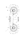
- FIG. 1 is a side view of a railway vehicle carriage 1 according to an embodiment.
- a bogie 1 for a railway vehicle includes a bogie frame 3 that supports a vehicle body 100 via an air spring 2.
- the carriage frame 3 has a pair of side beams 4 extending in the vehicle longitudinal direction on both sides in the vehicle width direction, and a lateral beam (not shown) extending in the vehicle width direction by connecting the pair of side beams 4 to each other.
- axles 6 extending along the vehicle width direction are arranged.
- Wheels 7 are respectively fixed to both sides of the axle 6 in the vehicle width direction.
- Bearings 8 that rotatably support the axle 6 on the outer side in the vehicle width direction than the wheels 7 are provided at both ends of the axle 6 in the vehicle width direction.
- the bearing 8 includes an inner ring (not shown), an outer ring 8a (see FIG. 2), and rolling elements (not shown) sandwiched between the inner ring and the outer ring 8a.
- the bearing 8 is accommodated in the axle box 11 of the axle box device 10.
- the axle box 11 has an axle box main body portion 12, an axial beam portion 13 (connecting portion), and a spring receiving portion 14.
- the axle box body 12 houses the bearing 8.
- the shaft beam portion 13 is connected to the carriage frame 3.
- the shaft beam portion 13 integrally extends from the axle box main body portion 12 toward the vehicle longitudinal direction center of the carriage 1 in the vehicle longitudinal direction, and the distal end portion thereof is elastically connected to the side beam 4 via the rubber bush 15. Is done.
- the spring receiver 14 is provided on the upper portion of the axle box main body 12.
- a coil spring 16 that extends and contracts in the vertical direction is interposed between an end 4 a of the side beam 4 in the longitudinal direction of the vehicle and the spring receiving portion 14 of the axle box 11.
- a temperature sensor unit 20 with a wireless communication function is attached to the lower part of the axle box 11.
- FIG. 2 is a partially sectional side view of the axle box device 10 having the temperature sensor unit 20 with a wireless communication function of the cart 1 shown in FIG.
- the axle box device 10 includes an axle box 11, a temperature sensor unit 20 with a wireless communication function, and a pair of elastic devices 21.
- the axle box 11 includes an upper axle box element 17 (first axle box element) that covers an upper area (first area) of the outer peripheral surface of the outer ring 8a of the bearing 8, and a lower area (first area) of the outer peripheral surface of the outer ring 8a of the bearing 8.
- a lower axle box element 18 (second axle box element) covering the second area).
- the upper shaft box element 17 is provided with a part of the shaft box main body 12, a shaft beam portion 13, and a spring receiving portion 14.
- the lower shaft box element 18 is provided with the other portion of the shaft box main body 12.
- the surface where the upper shaft box element 17 covers the outer peripheral surface of the outer ring 8 a of the bearing 8 is larger than the surface where the lower shaft box element 18 covers the outer peripheral surface of the outer ring 8 a of the bearing 8.
- the lower end of the upper shaft box element 17 is located below the rotation axis X of the bearing 8.
- the lower shaft box element 18 has a smaller vertical dimension than the upper shaft box element 17.
- the lower axle box element 18 is detachably attached to the upper axle box element 17 by bolts B from below.
- the temperature sensor unit 20 with a wireless communication function is attached to the lower shaft box element 18 in order to detect the temperature of the outer ring 8a of the bearing 8. Between the outer peripheral surface (lower surface) of the outer ring 8a of the bearing 8 and the lower shaft box element 18, a unit housing space S for housing the temperature sensor unit 20 with a wireless communication function is formed.
- the temperature sensor unit 20 with the wireless communication function projects downward from the lower shaft box element 18 through the opening 18b formed in the bottom wall portion 18a of the lower shaft box element 18 in a state of being housed in the unit housing space S. That is, the lower end portion of the temperature sensor unit 20 with the wireless communication function is located below the lower shaft box element 18 and exposed to the outside of the shaft box 11.
- the temperature sensor unit 20 with a wireless communication function is attached to the lower shaft box element 18 via a pair of elastic devices 21.
- the pair of elastic devices 21 are housed in the unit housing space S and are located on both sides of the cover 41.
- the elastic device 21 includes an elastic body 21a, a metal upper fixture 21b provided on the upper surface of the elastic body 21a, and a metal lower fixture 21c provided on the lower surface of the elastic body 21a.
- the upper fixture 21b and the lower fixture 21c can be displaced relative to each other in the vertical direction and the horizontal direction by elastic deformation of the elastic body 21a.
- the elastic device 21 is installed in a state where the elastic body 21a is compressed in the vertical direction, and wireless communication is performed such that the temperature sensor unit 20 with a wireless communication function is pressed against the outer ring 8a toward the rotation axis X (center) of the bearing 8.
- the temperature sensor unit with function 20 is energized.
- the axle box 11 has a stopper portion 46 that regulates the displacement around the rotation axis X of the temperature sensor unit 20 with the wireless communication function within a predetermined range.
- FIG. 3 is a side view of the temperature sensor unit 20 with the wireless communication function shown in FIG. 2 attached to the axle box 11.
- FIG. 4 is an exploded side view of the temperature sensor unit 20 with the wireless communication function shown in FIG.
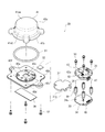
- FIG. 5 is an exploded perspective view of the temperature sensor unit 20 with the wireless communication function shown in FIG. 6 is a perspective view of the temperature sensor unit 20 with the wireless communication function shown in FIG. 3 with the cover 41 removed.
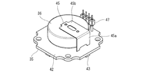
- FIG. 7 is a perspective view of the wireless communication board 35 and the battery 36 of the temperature sensor unit 20 with the wireless communication function shown in FIG. 4 to 6 are shown upside down from FIG. 3, and the spacer 49 is not shown in FIGS.
- the temperature sensor unit 20 with a wireless communication function includes a housing 31, a heat conductive sheet 32, a temperature sensor 33, a sensor substrate 34, a wireless communication board 35, a battery 36, and heat insulation. A material 37 and a spacer 49 are provided.
- the temperature sensor unit 20 has a temperature detection function, a wireless communication function, and a power supply function.
- the housing 31 is a case that houses a heat conductive sheet 32, a temperature sensor 33, a sensor substrate 34, a wireless communication board 35, a battery 36, and a heat insulating material 37.
- the housing 31 includes a contact member 38, a heat conductive sheet 39, a base plate 40, and a cover 41.
- the contact member 38 and the base plate 40 are made of a metal having thermal conductivity, for example, a metal having high thermal conductivity such as an aluminum alloy.
- the heat conductive sheet 39 is made of a material having elasticity and heat conductivity, for example, heat conductive silicone rubber.
- the cover 41 is made of a non-conductive material (for example, resin), for example, glass fiber reinforced resin.
- the cover 41 includes an accommodating portion 41a having a concave cross section and a flange portion 41b that protrudes laterally from the accommodating portion 41a.
- the accommodating portion 41a includes a bottom plate portion 41aa having a dome shape that swells away from the base plate 40, and a cylindrical side plate portion 41ab extending from the outer peripheral edge of the bottom plate portion 41aa toward the flange portion 41b.
- the side plate portion 41ab is cylindrical.
- a metal nut (not shown) to which the screw 52 is screwed is embedded in the flange portion 41b.
- the contact member 38 includes a heat receiving portion 38a formed with an arc-shaped heat receiving surface 38c (upper surface) that is in surface contact with the outer peripheral surface of the outer ring 8a of the bearing 8, and a shaft box mounting portion 38b that protrudes laterally from the heat receiving portion 38a.
- a heat conductive sheet 39 is sandwiched between the contact member 38 and the base plate 40 in a compressed state.
- the base plate 40 includes a main body portion 40a, a cover attachment portion 40b provided around the main body portion 40a, and a shaft box attachment portion 40c protruding sideways from the cover attachment portion 40b.
- the main body portion 40a is thicker than the cover attachment portion 40b.
- the main body 40 a holds the heat conductive sheet 32, the temperature sensor 33, the sensor substrate 34, the wireless communication board 35, the battery 36, and the heat insulating material 37.
- a recess 40d is formed on the surface of the base plate 40 facing the heat conductive sheet 39, and the heat conductive sheet 39 is accommodated in the recess 40d.
- the contact box 38 and the axle box attachment portions 38b and 40c of the base plate 40 are attached to the lower axle box element 18 via the elastic device 21.
- the cover 41 is attached to the cover attachment portion 40 b of the base plate 40 with screws 52.
- the cover 41 covers the heat conductive sheet 32, the temperature sensor 33, the sensor substrate 34, the wireless communication board 35, the battery 36, and the heat insulating material 37 from below.
- the heat conductive sheet 32 has insulating properties and is sandwiched between the base plate 40 and the temperature sensor 33 in a compressed state. That is, the detection unit of the temperature sensor 33 is pressed against the heat conductive sheet 32.
- a recess 40e is formed on the surface of the main body 40a of the base plate 40 facing the temperature sensor 33, and the heat conductive sheet 32 is positioned and accommodated in the recess 40e.
- the heat conductive sheet 32 is made of a material having insulating properties, elasticity, and heat conductivity, for example, heat conductive silicone rubber.
- the heat of the outer ring 8 a of the bearing 8 is transmitted in the order of the contact member 38, the heat conduction sheet 39, the base plate 40, the heat conduction sheet 32, and the temperature sensor 33.
- the temperature sensor 33 is mounted on the upper surface of the sensor substrate 34.
- the sensor board 34 has a sensor circuit that outputs an analog temperature signal detected by the temperature sensor 33 to a conversion board 42 described later.
- the sensor board 34 and the wireless communication board 35 are arranged in the same direction, specifically, in a direction along the tangential direction of the outer peripheral surface of the outer ring 8a of the bearing 8. In other words, the sensor substrate 34 and the wireless communication board 35 are arranged in a posture in which the main surfaces thereof face the outer peripheral surface of the outer ring 8 a of the bearing 8.
- the wireless communication board 35 includes a conversion board 42 and a wireless communication module 43.
- the conversion board 42 has a conversion circuit that converts an analog temperature signal from the temperature sensor 33 into a digital temperature signal.
- one of the conversion board 42 and the sensor board 34 When viewed from the normal direction of the wireless communication board 35, one of the conversion board 42 and the sensor board 34 has a shape including either one.
- the conversion board 42 and the sensor board 34 have the same outline shape, and are arranged such that their outlines coincide with each other when viewed from the normal direction of the wireless communication board 35.
- the conversion board 42 and the sensor board 34 are connected via connectors 47 and 48 extending in the vertical direction.
- the wireless communication module 43 is mounted on the conversion board 42 and wirelessly transmits a digital temperature signal from the conversion board 42 to the outside of the temperature sensor unit 20 with a wireless communication function (for example, a radio reception device of a railway vehicle).
- the battery 36 supplies power to the temperature sensor 33, the sensor board 34, and the wireless communication board 35.
- the first electrode 44 that is either the positive electrode or the negative electrode
- the second electrode 45 that is either the positive electrode or the negative electrode. And are provided.
- the size of the battery 36 in the direction along the wireless communication board 35 is longer than the size in the thickness direction of the wireless communication board 35.
- the battery 36 is a button battery.
- the first electrode 44 contacts the electrode on one side of the battery 36
- the second electrode 45 contacts the electrode on the other side of the battery 36.
- the second electrode 45 includes a vertical plate portion 45 a protruding from the conversion substrate 42 and a horizontal plate portion 45 b protruding from the vertical plate portion 45 a along the other surface of the battery 36.
- the battery 36 is sandwiched between the horizontal plate portion 45 b of the second electrode 45 and the first electrode 44. That is, in the present embodiment, the second electrode 45 serves as a holder for storing the battery 36.
- the electric power from the battery 36 is supplied to the wireless communication board 35 via the first electrode 44 and the second electrode 45, and is supplied to the sensor substrate 34 and the temperature sensor 33 from the wireless communication board 35.
- the heat insulating material 37 is interposed between the sensor substrate 34 and the battery 36 and has a larger area than the battery 36.
- the spacer 49 is disposed between the sensor substrate 34 and the wireless communication board 35, and forms a space between the sensor substrate 34 and the wireless communication board 35.
- the spacer 49 is made of a non-conductive material (for example, resin). The spacer 49 is fixed by being press-fitted into the hole 40 f of the main body 40 a of the base plate 40 through the hole 34 a of the sensor substrate 34.
- a screw 50 is fixed to the spacer 49 through the hole 42 a of the conversion substrate 42.
- a cutout portion 37 a into which the spacer 49 is fitted is formed on the outer peripheral portion of the heat insulating material 37.
- the battery 36 and the heat insulating material 37 are disposed in a space formed by the spacer 49.
- the contact member 38, the heat conductive sheet 39, the base plate 40, the heat conductive sheet 32, the temperature sensor 33, the sensor substrate 34, the heat insulating material 37, the battery 36, and the wireless communication board 35 are provided in the temperature sensor unit 20 with the wireless communication function. , Arranged in this order from top to bottom.
- the cover 41 is fixed to the base plate 40b by fastening the flange portion 41b to the cover mounting portion 40b of the base plate 40 with a screw 52 via a seal member 51 (for example, an O-ring).
- a seal member 51 for example, an O-ring.
- the cover 41 is fitted to the thick main body 40a of the base plate 40 from the outside.
- the temperature sensor unit 20 with the wireless communication function is attached to the axle box 11
- at least the bottom plate portion 41aa of the accommodating portion 41a of the cover 41 is exposed to the outside of the axle box 11 through the opening 18b.
- a part of the bottom plate portion 41aa and the side plate portion 41ab is exposed to the outside of the axle box 11 through the opening 18b.
- the plate-like wireless communication board 35 is arranged in the direction along the tangential direction of the bearing 8, so that the protrusion amount of the temperature sensor unit 20 with the wireless communication function from the axle box 11 is suppressed. be able to.
- the battery 36 is disposed between the temperature sensor 33 and the wireless communication board 35, and the temperature sensor 33, the battery 36, and the wireless communication board 35 overlap each other when viewed from the normal direction of the wireless communication board 35.
- the installation area of the temperature sensor unit 20 with the wireless communication function can also be reduced. Therefore, it is possible to suppress a decrease in the degree of freedom of attachment to the axle box 11 while preventing the temperature sensor unit 20 with the wireless communication function from being damaged by flying stones or the like.
- the arc-shaped heat receiving surface 38c of the contact member 38 is in surface contact with the outer peripheral surface of the outer ring 8a of the bearing 8, heat transfer from the outer ring 8a to the contact member 38 is stabilized, and the detection accuracy of the temperature sensor 33 is improved. To do.
- the base plate 40 is made of metal and the cover 41 is made of a non-conductive material, the cover 41 secures component protection and wireless communication stability while ensuring heat conductivity and rigidity. be able to.
- the insulating heat conductive sheet 32 is sandwiched between the base plate 40 and the temperature sensor 33, the heat between the base plate 40 and the temperature sensor 33 can be transferred between the base plate 40 and the temperature sensor 33. Electrical insulation can be achieved.
- the sensor substrate 34 on which the temperature sensor 33 is mounted is disposed in the same direction as the wireless communication board 35, and the sensor substrate 34 is disposed so that the temperature sensor 33, the battery 36, and the wireless communication board 35 overlap each other. It can contribute to suppression of the protrusion amount and installation area of the temperature sensor unit 20 with the wireless communication function.
- the battery 36 is housed between the first electrode 44 and the second electrode 45 (holder) provided in the wireless communication board 35 in the space formed by the spacer 49, the battery 36 is compact while suppressing temperature rise.
- Various elements such as the battery 36 can be arranged in the battery.
- the battery 36 has a longer dimension in the direction along the wireless communication board 35 than the dimension in the thickness direction of the wireless communication board 35, it can contribute to the suppression of the protruding amount and installation area of the temperature sensor unit 20 with the wireless communication function.
- the cover 41 has a dome-shaped bottom plate portion 41aa of the housing portion 41a, even if an obstacle such as a stepping stone hits the bottom plate portion 41aa of the cover 41, the obstacle can be passed away, and the cover 41 is preferably damaged. Can be prevented. Further, since the cover 41 has a cylindrical side plate portion 41ab of the accommodating portion 41a, the cover 41 can be more preferably prevented from being damaged when the side plate portion 41ab is also exposed from the axle box 11.
- the present invention is not limited to the above-described embodiment, and the configuration can be changed, added, or deleted.
- the heat conductive sheet 39 between the contact member 38 and the base plate 40 may be eliminated, and the contact member 38 may be formed integrally with the base plate 40. That is, a heat receiving surface that is in surface contact with the outer ring 8a may be provided on the base plate.
- the battery 36 may be attached to the sensor substrate 34 without being attached to the wireless communication board 35.
- the heat insulating material 37 may be abolished.
- the temperature sensor unit 20 with the wireless communication function may be attached to a gear box or a motor of the carriage 1.
Landscapes
- Engineering & Computer Science (AREA)
- Physics & Mathematics (AREA)
- General Physics & Mathematics (AREA)
- Mechanical Engineering (AREA)
- Computer Networks & Wireless Communication (AREA)
- General Engineering & Computer Science (AREA)
- Health & Medical Sciences (AREA)
- Biomedical Technology (AREA)
- General Health & Medical Sciences (AREA)
- Arrangements For Transmission Of Measured Signals (AREA)
- Rolling Contact Bearings (AREA)
- Measuring Temperature Or Quantity Of Heat (AREA)
Priority Applications (4)
| Application Number | Priority Date | Filing Date | Title |
|---|---|---|---|
| CN201680047852.3A CN107851371B (zh) | 2015-10-08 | 2016-09-01 | 铁道车辆用转向架的附有无线通信功能的温度传感器单元 |
| US15/766,878 US10793171B2 (en) | 2015-10-08 | 2016-09-01 | Wireless communication function-equipped temperature sensor unit of railcar bogie |
| SG11201802899UA SG11201802899UA (en) | 2015-10-08 | 2016-09-01 | Wireless communication function-equipped temperature sensor unit of railcar bogie |
| KR1020187010636A KR101960865B1 (ko) | 2015-10-08 | 2016-09-01 | 철도 차량용 대차의 무선통신기능이 달린 온도센서 유닛 |
Applications Claiming Priority (2)
| Application Number | Priority Date | Filing Date | Title |
|---|---|---|---|
| JP2015-200002 | 2015-10-08 | ||
| JP2015200002A JP6484156B2 (ja) | 2015-10-08 | 2015-10-08 | 鉄道車両用台車の無線通信機能付き温度センサユニット |
Publications (1)
| Publication Number | Publication Date |
|---|---|
| WO2017061069A1 true WO2017061069A1 (ja) | 2017-04-13 |
Family
ID=58488300
Family Applications (1)
| Application Number | Title | Priority Date | Filing Date |
|---|---|---|---|
| PCT/JP2016/003989 WO2017061069A1 (ja) | 2015-10-08 | 2016-09-01 | 鉄道車両用台車の無線通信機能付き温度センサユニット |
Country Status (7)
| Country | Link |
|---|---|
| US (1) | US10793171B2 (zh) |
| JP (1) | JP6484156B2 (zh) |
| KR (1) | KR101960865B1 (zh) |
| CN (1) | CN107851371B (zh) |
| SG (1) | SG11201802899UA (zh) |
| TW (1) | TWI619096B (zh) |
| WO (1) | WO2017061069A1 (zh) |
Cited By (1)
| Publication number | Priority date | Publication date | Assignee | Title |
|---|---|---|---|---|
| JP7438624B2 (ja) | 2020-02-12 | 2024-02-27 | 川崎車両株式会社 | 昇温検知センサ、昇温検知システム、及び昇温検知ユニット |
Families Citing this family (5)
| Publication number | Priority date | Publication date | Assignee | Title |
|---|---|---|---|---|
| JP6688158B2 (ja) * | 2015-10-08 | 2020-04-28 | 川崎重工業株式会社 | 鉄道車両用台車の温度センサユニット付き軸箱装置及び温度検出装置 |
| EP3354532B1 (en) * | 2017-01-26 | 2020-05-27 | Rail Vision Europe Ltd | Vehicle mounted monitoring system |
| CN107621607B (zh) * | 2017-08-21 | 2020-11-13 | 中山市卓的电子科技有限公司 | 电池性能测试方法、测试终端、可读存储介质及测试系统 |
| US11592499B2 (en) | 2019-12-10 | 2023-02-28 | Barnes Group Inc. | Wireless sensor with beacon technology |
| JP7227639B2 (ja) * | 2021-02-25 | 2023-02-22 | 株式会社ミヤワキ | 計測装置 |
Citations (5)
| Publication number | Priority date | Publication date | Assignee | Title |
|---|---|---|---|---|
| JPH0642983A (ja) * | 1992-07-24 | 1994-02-18 | Omron Corp | 物理量センサ及びその製造方法 |
| JPH10217964A (ja) * | 1997-01-31 | 1998-08-18 | Ntn Corp | 鉄道車両軸受異常検出装置 |
| JP2007327645A (ja) * | 2007-07-12 | 2007-12-20 | Ntn Corp | 車両用軸受装置 |
| JP2008168761A (ja) * | 2007-01-11 | 2008-07-24 | Railway Technical Res Inst | 鉄道車両の異常検知方法およびそのシステム |
| JP2009535697A (ja) * | 2006-04-28 | 2009-10-01 | エーエスエフ−キーストーン インコーポレイテッド | センサインターフェース |
Family Cites Families (21)
| Publication number | Priority date | Publication date | Assignee | Title |
|---|---|---|---|---|
| US3727045A (en) * | 1970-12-28 | 1973-04-10 | Minnesota Mining & Mfg | Sensing system and device |
| JP2003307228A (ja) | 2002-04-12 | 2003-10-31 | Nsk Ltd | センサ付軸受装置 |
| JP4963006B2 (ja) * | 2002-09-09 | 2012-06-27 | Ntn株式会社 | ワイヤレスセンサシステムおよびワイヤレスセンサ付車輪用軸受装置 |
| JP4521594B2 (ja) * | 2002-12-10 | 2010-08-11 | 株式会社ジェイテクト | 回転センサ付き転がり軸受装置 |
| US7869909B2 (en) * | 2004-07-26 | 2011-01-11 | Harold Harrison | Stress monitoring system for railways |
| JP2006106917A (ja) * | 2004-10-01 | 2006-04-20 | Jtekt Corp | 駆動軸用ワイヤレスユニット、ベアリングカップグリース注入孔用蓋、及び駆動軸監視システム |
| US8430363B2 (en) * | 2004-12-06 | 2013-04-30 | Progress Rail Services Corp | Train wheel bearing temperature detection |
| RU2472130C2 (ru) * | 2008-03-05 | 2013-01-10 | Аб Скф | Устройство для крепления к вращающейся части вагонной оси |
| US8244411B2 (en) * | 2008-05-27 | 2012-08-14 | Baker David A | Orientation-based wireless sensing apparatus |
| SE534724C2 (sv) * | 2009-12-07 | 2011-11-29 | Eric Berggren | Förfarande för att bestämma rälernas spänningsfria temperatur och/eller spårets sidomotstånd |
| IT1399071B1 (it) * | 2010-03-23 | 2013-04-05 | Torino Politecnico | Dispositivo per diagnostica di carrelli ferroviari mediante l'applicazione di una vite di misura e trasmissione ad autonomia energetica e relativo metodo di controllo |
| US9365223B2 (en) | 2010-08-23 | 2016-06-14 | Amsted Rail Company, Inc. | System and method for monitoring railcar performance |
| JP2012189187A (ja) * | 2011-03-14 | 2012-10-04 | Ntn Corp | 回転センサ付軸受 |
| SE537691C2 (sv) * | 2011-10-26 | 2015-09-29 | Creator Teknisk Utveckling Ab | Trådlös sensoranordning för en högspänningsmiljö och systeminnefattande sådan |
| WO2013129255A1 (ja) * | 2012-02-28 | 2013-09-06 | ナブテスコ株式会社 | 鉄道車両のエネルギ回生装置及び鉄道車両の駆動アシスト装置 |
| CN104335023A (zh) | 2012-04-24 | 2015-02-04 | Skf公司 | 轴承监控方法和系统 |
| DE112013006872T5 (de) * | 2013-03-27 | 2015-12-24 | Aktiebolaget Skf | Nabeneinheit |
| ITTO20130625A1 (it) * | 2013-07-23 | 2015-01-24 | Skf Ab | Sistema di misura della temperatura di un cuscinetto di rotolamento in una boccola ferroviaria e metodo associato |
| CA2935094C (en) | 2013-12-24 | 2018-10-16 | Amsted Rail Company, Inc. | System and method for detecting operational anomalies in train consists and railcars |
| CN107851623B (zh) * | 2015-06-25 | 2021-04-16 | 积水保力马科技株式会社 | 导热片 |
| IT201600094177A1 (it) * | 2016-09-20 | 2018-03-20 | Ecm S P A | Dispositivo di copertura di una boccola d’assile comprendente un generatore elettrico |
-
2015
- 2015-10-08 JP JP2015200002A patent/JP6484156B2/ja active Active
-
2016
- 2016-09-01 CN CN201680047852.3A patent/CN107851371B/zh active Active
- 2016-09-01 US US15/766,878 patent/US10793171B2/en active Active
- 2016-09-01 KR KR1020187010636A patent/KR101960865B1/ko active IP Right Grant
- 2016-09-01 WO PCT/JP2016/003989 patent/WO2017061069A1/ja active Application Filing
- 2016-09-01 SG SG11201802899UA patent/SG11201802899UA/en unknown
- 2016-10-05 TW TW105132184A patent/TWI619096B/zh active
Patent Citations (5)
| Publication number | Priority date | Publication date | Assignee | Title |
|---|---|---|---|---|
| JPH0642983A (ja) * | 1992-07-24 | 1994-02-18 | Omron Corp | 物理量センサ及びその製造方法 |
| JPH10217964A (ja) * | 1997-01-31 | 1998-08-18 | Ntn Corp | 鉄道車両軸受異常検出装置 |
| JP2009535697A (ja) * | 2006-04-28 | 2009-10-01 | エーエスエフ−キーストーン インコーポレイテッド | センサインターフェース |
| JP2008168761A (ja) * | 2007-01-11 | 2008-07-24 | Railway Technical Res Inst | 鉄道車両の異常検知方法およびそのシステム |
| JP2007327645A (ja) * | 2007-07-12 | 2007-12-20 | Ntn Corp | 車両用軸受装置 |
Cited By (1)
| Publication number | Priority date | Publication date | Assignee | Title |
|---|---|---|---|---|
| JP7438624B2 (ja) | 2020-02-12 | 2024-02-27 | 川崎車両株式会社 | 昇温検知センサ、昇温検知システム、及び昇温検知ユニット |
Also Published As
| Publication number | Publication date |
|---|---|
| US10793171B2 (en) | 2020-10-06 |
| KR101960865B1 (ko) | 2019-07-17 |
| TWI619096B (zh) | 2018-03-21 |
| CN107851371A (zh) | 2018-03-27 |
| JP2017072498A (ja) | 2017-04-13 |
| JP6484156B2 (ja) | 2019-03-13 |
| SG11201802899UA (en) | 2018-05-30 |
| KR20180055855A (ko) | 2018-05-25 |
| US20180290670A1 (en) | 2018-10-11 |
| CN107851371B (zh) | 2020-04-07 |
| TW201729168A (zh) | 2017-08-16 |
Similar Documents
| Publication | Publication Date | Title |
|---|---|---|
| JP6484156B2 (ja) | 鉄道車両用台車の無線通信機能付き温度センサユニット | |
| WO2017187846A1 (ja) | 鉄道車両用台車の軸受温度検出装置 | |
| CN107785512B (zh) | 电池组件和具有这种电池组件的车辆 | |
| US8174168B2 (en) | Piezoelectric power generating device | |
| US20190032710A1 (en) | Sensor device with mounting element | |
| JP4637926B2 (ja) | 電子装置および液圧ユニット | |
| WO2018042988A1 (ja) | 電動駆動装置及び電動パワーステアリング装置 | |
| JP6543663B2 (ja) | 車両用アンテナ装置 | |
| JP6688158B2 (ja) | 鉄道車両用台車の温度センサユニット付き軸箱装置及び温度検出装置 | |
| PL1681534T3 (pl) | Poziomnica laserowa | |
| JP7259993B2 (ja) | 配線モジュール、および、蓄電モジュール | |
| JP5019957B2 (ja) | バルブ一体型トランスポンダ | |
| WO2018030535A1 (ja) | 台座付きセンサモジュール | |
| WO2017061068A1 (ja) | 鉄道車両用台車の温度センサユニット付き軸箱装置及び温度検出装置 | |
| JP5242297B2 (ja) | 電気接続箱 | |
| CN210661162U (zh) | 减震弹性垫、飞控组件和无人飞行器 | |
| JP7117266B2 (ja) | 電子機器、撮像装置、および移動体 | |
| JP2011054975A (ja) | 電子装置 | |
| JP2006329231A (ja) | センサ付軸受装置 | |
| US20210072070A1 (en) | Three point mount for a vibration sensing apparatus | |
| JP2023164253A (ja) | 車両、特に単車のコンポーネントにおいて位置固定するための位置固定装置を備えた通信ユニット | |
| JP2005206013A (ja) | タイヤ内圧警報装置、およびタイヤ内圧警報装置の取付け方法 |
Legal Events
| Date | Code | Title | Description |
|---|---|---|---|
| 121 | Ep: the epo has been informed by wipo that ep was designated in this application |
Ref document number: 16853228 Country of ref document: EP Kind code of ref document: A1 |
|
| WWE | Wipo information: entry into national phase |
Ref document number: 11201802899U Country of ref document: SG |
|
| WWE | Wipo information: entry into national phase |
Ref document number: 15766878 Country of ref document: US |
|
| NENP | Non-entry into the national phase |
Ref country code: DE |
|
| ENP | Entry into the national phase |
Ref document number: 20187010636 Country of ref document: KR Kind code of ref document: A |
|
| 122 | Ep: pct application non-entry in european phase |
Ref document number: 16853228 Country of ref document: EP Kind code of ref document: A1 |