WO2017057252A1 - ディーゼルエンジン - Google Patents
ディーゼルエンジン Download PDFInfo
- Publication number
- WO2017057252A1 WO2017057252A1 PCT/JP2016/078229 JP2016078229W WO2017057252A1 WO 2017057252 A1 WO2017057252 A1 WO 2017057252A1 JP 2016078229 W JP2016078229 W JP 2016078229W WO 2017057252 A1 WO2017057252 A1 WO 2017057252A1
- Authority
- WO
- WIPO (PCT)
- Prior art keywords
- fuel injection
- injection pump
- cam
- diesel engine
- diameter
- Prior art date
Links
Images


Classifications
-
- F—MECHANICAL ENGINEERING; LIGHTING; HEATING; WEAPONS; BLASTING
- F02—COMBUSTION ENGINES; HOT-GAS OR COMBUSTION-PRODUCT ENGINE PLANTS
- F02M—SUPPLYING COMBUSTION ENGINES IN GENERAL WITH COMBUSTIBLE MIXTURES OR CONSTITUENTS THEREOF
- F02M59/00—Pumps specially adapted for fuel-injection and not provided for in groups F02M39/00 -F02M57/00, e.g. rotary cylinder-block type of pumps
- F02M59/02—Pumps specially adapted for fuel-injection and not provided for in groups F02M39/00 -F02M57/00, e.g. rotary cylinder-block type of pumps of reciprocating-piston or reciprocating-cylinder type
- F02M59/10—Pumps specially adapted for fuel-injection and not provided for in groups F02M39/00 -F02M57/00, e.g. rotary cylinder-block type of pumps of reciprocating-piston or reciprocating-cylinder type characterised by the piston-drive
- F02M59/102—Mechanical drive, e.g. tappets or cams
-
- F—MECHANICAL ENGINEERING; LIGHTING; HEATING; WEAPONS; BLASTING
- F02—COMBUSTION ENGINES; HOT-GAS OR COMBUSTION-PRODUCT ENGINE PLANTS
- F02M—SUPPLYING COMBUSTION ENGINES IN GENERAL WITH COMBUSTIBLE MIXTURES OR CONSTITUENTS THEREOF
- F02M39/00—Arrangements of fuel-injection apparatus with respect to engines; Pump drives adapted to such arrangements
- F02M39/02—Arrangements of fuel-injection apparatus to facilitate the driving of pumps; Arrangements of fuel-injection pumps; Pump drives
-
- F—MECHANICAL ENGINEERING; LIGHTING; HEATING; WEAPONS; BLASTING
- F02—COMBUSTION ENGINES; HOT-GAS OR COMBUSTION-PRODUCT ENGINE PLANTS
- F02M—SUPPLYING COMBUSTION ENGINES IN GENERAL WITH COMBUSTIBLE MIXTURES OR CONSTITUENTS THEREOF
- F02M59/00—Pumps specially adapted for fuel-injection and not provided for in groups F02M39/00 -F02M57/00, e.g. rotary cylinder-block type of pumps
- F02M59/02—Pumps specially adapted for fuel-injection and not provided for in groups F02M39/00 -F02M57/00, e.g. rotary cylinder-block type of pumps of reciprocating-piston or reciprocating-cylinder type
- F02M59/10—Pumps specially adapted for fuel-injection and not provided for in groups F02M39/00 -F02M57/00, e.g. rotary cylinder-block type of pumps of reciprocating-piston or reciprocating-cylinder type characterised by the piston-drive
-
- F—MECHANICAL ENGINEERING; LIGHTING; HEATING; WEAPONS; BLASTING
- F02—COMBUSTION ENGINES; HOT-GAS OR COMBUSTION-PRODUCT ENGINE PLANTS
- F02N—STARTING OF COMBUSTION ENGINES; STARTING AIDS FOR SUCH ENGINES, NOT OTHERWISE PROVIDED FOR
- F02N19/00—Starting aids for combustion engines, not otherwise provided for
Definitions
- the present invention relates to the technology of a diesel engine.
- the problem to be solved by the present invention is to provide a diesel engine capable of preventing continuation of reverse rotation in the event that reverse rotation occurs during operation.
- a camshaft driven by a crankshaft a camshaft provided on the camshaft to drive a fuel injection pump, a maximum diameter portion, a minimum diameter portion, and a diameter smaller than the maximum diameter portion.
- an intermediate portion having a diameter larger than that of the minimum diameter portion, and an inclined portion that changes from the intermediate step portion to the minimum diameter portion, and is formed along the reverse rotation direction from the intermediate step portion through the inclined portion to the outermost portion.
- the fuel injection pump driving cam has an upper step portion having a smaller diameter than the maximum diameter portion and a larger diameter than the middle step portion, and is reversely rotated. From the middle step portion through the upper step portion to the inclined portion along the direction is formed.
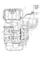
- the partial cross section front view which showed the structure of the diesel engine The partial cross section side view which showed the structure of the diesel engine lower part.
- the diesel engine 1 will be described with reference to FIGS. 1 to 3.
- the configuration of the diesel engine 1 is represented by a front view with a partial cross-sectional view.
- the lower configuration of the diesel engine 1 is represented by a side view with a partial cross-sectional view.
- the upper structure of the engine 1 is represented by a side view with a partial cross-sectional view.
- the diesel engine 1 is an embodiment according to the diesel engine of the present invention.
- the diesel engine 1 of the present embodiment is a single-cylinder air-cooled diesel engine.
- the main body of the diesel engine 1 is composed of an upper cylinder block 2 and a lower crankcase 3.
- a cylinder 2a is formed in the vertical direction.
- a piston 4 is accommodated in the cylinder 2a.
- the cylinder head 7 is disposed above the cylinder block 2.
- a bonnet cover 8 is disposed above the cylinder head 7.
- the inside of the bonnet cover 8 is formed as a valve arm chamber 8a.
- the intake valve arm 27, the exhaust valve arm 28, the upper end of the intake valve 31, the upper end of the exhaust valve 32, and the upper end of the intake push rod 25 are formed.
- the upper end of the exhaust push rod 26 are internally provided (see FIG. 3).
- a muffler 9 is disposed on one side (left side in FIG. 1) of the bonnet cover 8 at the top of the diesel engine 1.
- a fuel tank 10 is disposed on the other side of the bonnet cover 8 (the right side in FIG. 1).
- crankshaft 5 is supported on crankcase 3.
- the crankshaft 5 is connected to the piston 4 by a connecting rod 6.
- a balance weight and a governor device 11 are arranged inside the crankcase 3.
- a fuel injection pump 12 and a cam shaft 13 are arranged above the governor device 11.
- the camshaft 13 is pivotally supported by the crankcase 3 so as to be parallel to the crankshaft 5.
- a cam gear 17 is fixed to one end of the cam shaft 13.
- the cam gear 17 is meshed with a gear 18 fixed to one end of the crankshaft 5 so that a driving force can be transmitted from the crankshaft 5 to the camshaft 13 via the gear 18 and the cam gear 17.
- an intake cam 21 and an exhaust cam 22 are provided at predetermined intervals.
- a fuel injection pump driving cam 14 is provided between the intake cam 21 and the exhaust cam 22.
- the tappet 23 is in contact with the intake cam 21.
- the lower end of the intake push rod 25 is connected to the tappet 23.
- the upper end of the intake push rod 25 extends to the valve arm chamber 8 a inside the bonnet cover 8 through a rod hole opened in the vertical direction in the cylinder block 2 and the cylinder head 7.
- the upper end of the intake push rod 25 is in contact with the lower end on one side of the intake valve arm 27, and the upper end of the intake valve 31 is in contact with the lower end on the other side of the intake valve arm 27.
- the intake valve 31 is composed of a valve head 31 a at the lower end and a valve stem 31 b at the body, and is disposed above the piston 4.
- the valve head 31 a is disposed so as to be seated or separated from a valve seat formed on the lower surface of the cylinder head 7, and an intake port 7 a formed in the cylinder head 7 and a combustion chamber of the cylinder 2 a formed in the cylinder block 2. Can be communicated or blocked.
- the intake port 7 a communicates with an air cleaner 20 provided on one side surface (rear surface) of the cylinder head 7.
- valve rod 31 b penetrates the cylinder head 7 upward and protrudes slidably toward the bonnet cover 8, and its upper end is in contact with the intake valve arm 27.
- a spring 33 is fitted on the valve rod 31b, and the valve head 31a is urged by the spring 33 to slide upward, so that the intake valve 31 is closed.
- a tappet 24 is in contact with the exhaust cam 22.
- the lower end of the intake push rod 25 is connected to the tappet 23.
- the tappet 24 is connected to the lower end of the exhaust push rod 26.
- the upper end of the exhaust push rod 26 is extended to the valve arm chamber 8 a inside the bonnet cover 8 through a rod hole opened in the vertical direction in the cylinder block 2 and the cylinder head 7.
- the upper end of the exhaust push rod 26 is in contact with the lower end on one side of the exhaust valve arm 28, and the upper end of the exhaust valve 32 is in contact with the lower end on the other side of the exhaust valve arm 28.
- the exhaust valve 32 includes a valve head 32 a at the lower end and a valve stem 32 b at the body, and is disposed above the piston 4.
- the valve head 32 a is disposed so as to be seated or separated from a valve seat formed on the lower surface of the cylinder head 7, and an exhaust port 7 b formed in the cylinder head 7 and a combustion chamber of the cylinder 2 a formed in the cylinder block 2. Can be communicated or blocked.
- the exhaust port 7 b communicates with the muffler 9 through the exhaust manifold 29.
- valve rod 32 b penetrates the cylinder head 7 upward and protrudes slidably toward the bonnet cover 8, and its upper end is in contact with the exhaust valve arm 28.
- a spring 33 is fitted on the valve rod 32b, and the valve head 32a is urged by the spring 33 so as to slide upward, so that the exhaust valve 32 is closed.
- a fuel injection nozzle 15 is disposed between the intake valve 31 and the exhaust valve 32.
- the fuel injection nozzle 15 protrudes downward through the cylinder head 7 so that the tip (discharge portion) is located above the center of the cylinder 2a, and injects fuel supplied by the fuel injection pump 12 into the cylinder 2a. It can be done.
- the intake valve 31 is slid up and down through the intake push rod 25 and the intake valve arm 27 connected to the tappet 23 to open and close.
- the exhaust valve 32 is slid up and down through the exhaust push rod 26 and the exhaust valve arm 28 connected to the tappet 24 to open and close. That is, the intake valve 31 and the exhaust valve 32 are opened and closed in conjunction with the rotation of the intake cam 21 and the exhaust cam 22 of the cam shaft 13.
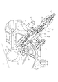
- the fuel injection pump 12 will be described with reference to FIG. In FIG. 4, the configuration of the fuel injection pump 12 is schematically shown in partial cross-sectional view.
- the fuel injection pump 12 is disposed together with the camshaft 13 above the governor device 11 disposed in the crankcase 3.
- a roller 42 supported by the tappet 41 is brought into contact with a fuel injection pump drive cam 14 provided between the intake cam 21 and the exhaust cam 22 of the camshaft 13 to drive the fuel injection pump.
- the rotation of the cam 14 causes the plunger 43 to reciprocate through the roller 42 and the tappet 41, and the fuel in the fuel tank 10 is sucked into the plunger barrel 45 from the suction portion 44.
- the roller 42 is raised by the further rotation of the fuel injection pump driving cam 14, and the plunger 43 is raised via the roller 42 and the tappet 41, whereby the plunger
- the fuel in the barrel 45 is compressed, the outlet valve 48 is opened, and a predetermined amount of fuel is supplied from the discharge portion 46 to the fuel injection nozzle 15 via the high pressure pipe 47 at a predetermined timing.
- the fuel injection amount by the fuel injection nozzle 15 can be adjusted by rotating the control lever 16 of the fuel injection pump 12 by the governor device 11 and changing the stroke of the plunger 43.
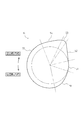
- the configuration of the fuel injection pump drive cam 14 will be described with reference to FIG. In FIG. 5, the fuel injection pump drive cam 14 is schematically shown in a front view. A two-dot chain line represents a boundary between the parts.
- the fuel injection pump drive cam 14 is configured to have different radii according to the reciprocation of the piston 4 and the rotation angle of the crankshaft 5.
- the fuel injection pump drive cam 14 has a minimum diameter portion 51, an inclined portion 52, a maximum diameter portion 53, an inclined portion 54, an intermediate step portion 55, and an inclined portion as portions having different diameters along the reverse rotation direction. 56 and a minimum diameter portion 51 are formed.
- the minimum diameter portion 51 is a portion having a minimum diameter in the fuel injection pump drive cam 14.
- the maximum diameter portion 53 is a portion having the maximum diameter in the fuel injection pump drive cam 14.
- the middle stage portion 55 is a portion having a smaller diameter than the maximum diameter portion 53 and a larger diameter than the minimum diameter portion 51.
- the inclined portion 52 is a portion that changes from the minimum diameter portion 51 to the maximum diameter portion 53 along the reverse rotation direction.
- the inclined portion 54 is a portion that changes from the maximum diameter portion 53 to the middle step portion 55 along the reverse rotation direction.
- the inclined portion 56 is a portion that changes from the middle step portion 55 to the minimum diameter portion 51 along the reverse rotation direction.
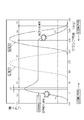
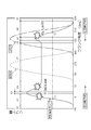
- the operation of the fuel injection pump drive cam 14 is schematically shown as a graph in which the horizontal axis represents the crank angle and the vertical axis represents the lift amount.
- the fuel cam lift is represented by a solid line
- the exhaust valve lift is represented by a broken line
- the intake valve lift is represented by a one-dot chain line
- the fuel pressure feed timing is represented by a two-dot chain line.
- the operation of the fuel injection pump drive cam 14 during normal rotation (in the direction from left to right in FIG. 6) will be described.
- the fuel cam lift amount is at the minimum position, and the plunger 43 of the fuel injection pump 12 is at the most extended position (uncompressed position).
- fuel injection is performed at a predetermined crank angle. More specifically, fuel pumping is started from the position of point P1 of the two-dot chain line in FIG. 6, and fuel is injected after the pumped fuel reaches the nozzle opening pressure. That is, the fuel injection timing comes after the point P1 of the fuel pumping timing, and the fuel pumping timing and the fuel injection timing deviate.
- the fuel cam lift amount is at the maximum position, and the plunger 43 of the fuel injection pump 12 is at the minimum contracted (compressed) position.
- the exhaust valve 32 is opened and closed, and the intake valve 31 begins to open.
- the intake valve 31 is open to at least approximately half of the fully open lift amount of the intake valve 31.
- the intake valve 31 is substantially fully opened at the stage where the roller 42 is in contact with the position where the middle stage portion 55 transitions to the inclined portion 56.
- the intake valve 31 is closed.
- the fuel injection pump drive cam 14 is formed such that the position at which the fuel injection pump drive cam 14 shifts from the middle stage portion 55 to the inclined portion 56 starts after the intake valve 31 opens at least half the maximum lift amount of the intake valve 31. Yes.
- the operation of the fuel injection pump drive cam 14 during reverse rotation (in the direction from right to left in FIG. 6) will be described.
- the plunger 43 of the fuel injection pump 12 is in the most extended position (uncompressed position).
- fuel is injected at a predetermined crank angle.
- the timing of fuel injection at the time of reverse rotation is different from the timing of fuel injection at the time of forward rotation.
- the fuel injection timing at the time of forward rotation and the fuel injection timing at the time of reverse rotation are deviated from the forward rotation side as seen from the point P2 of the fuel pumping timing as compared with the forward rotation side.
- the configuration of the fuel injection pump drive cam 74 will be described with reference to FIG.
- the fuel injection pump drive cam 74 is schematically shown in a front view.
- a two-dot chain line represents a boundary between the parts.
- the fuel injection pump drive cam 74 is configured to have different radii according to the reciprocation of the piston 4 and the rotation angle of the crankshaft 5.
- the drive cam 74 for the fuel injection pump has a minimum diameter portion 61, an inclined portion 62, a maximum diameter portion 63, an inclined portion 64, an intermediate step portion 65, an inclined portion 66, and an upper step portion as portions having different diameters in order along the reverse rotation direction. 67, the inclined portion 68, and the minimum diameter portion 61 are formed in this order.
- the minimum diameter portion 61 is a portion having a minimum diameter in the fuel injection pump drive cam 74.
- the maximum diameter portion 63 is a portion having a maximum diameter in the fuel injection pump drive cam 74.
- the middle stage portion 65 is a portion having a smaller diameter than the maximum diameter portion 63 and a larger diameter than the minimum diameter portion 61.
- the inclined portion 62 is a portion that changes from the smallest diameter portion 61 to the largest diameter portion 63 along the reverse rotation direction.
- the inclined portion 64 is a portion that changes from the maximum diameter portion 63 to the middle step portion 65 along the reverse rotation direction.
- the inclined portion 66 is a portion that changes from the middle step portion 65 to the upper step portion 67 along the reverse rotation direction.
- the upper step portion 67 is a portion having a smaller diameter than the maximum diameter portion 63 and a larger diameter than the middle step portion 65.
- the operation of the fuel injection pump drive cam 74 is schematically shown as a graph in which the horizontal axis represents the crank angle and the vertical axis represents the lift amount.
- the fuel cam lift is represented by a solid line
- the exhaust valve lift is represented by a broken line
- the intake valve lift is represented by a one-dot chain line
- the fuel pressure feed timing is represented by a two-dot chain line.
- the operation of the fuel injection pump drive cam 74 during normal rotation (in the direction from left to right in FIG. 8) will be described.
- the fuel cam lift amount is at the minimum position, and the plunger 43 of the fuel injection pump 12 is at the most extended position (uncompressed position).
- fuel injection is performed at a predetermined crank angle. More specifically, fuel pumping is started from the position of the point P1 of the two-dot chain line in FIG. 8, and the fuel is injected after the pumped fuel reaches the nozzle opening pressure. That is, the fuel injection timing comes after the point P1 of the fuel pumping timing, and the fuel pumping timing and the fuel injection timing deviate.
- the fuel cam lift amount is at the minimum position, and the plunger 43 of the fuel injection pump 12 is at the most contracted (compressed) position.
- the exhaust valve 32 is opened and closed, and the intake valve 31 starts to open.
- the intake valve 31 is in an open state up to at least approximately half of the fully opened lift amount of the intake valve 31. Then, at the stage where the roller 42 is in contact with the upper stage portion 67, the intake valve 31 is substantially fully opened. At the stage where the roller 42 starts to contact the minimum diameter portion 51, the intake valve 31 is closed.
- the fuel injection pump drive cam 74 is formed at a position where the upper stage portion 67 is formed at a position where the intake valve 31 is substantially fully open.
- the operation of the fuel injection pump drive cam 74 during reverse rotation (in the direction from right to left in FIG. 8) will be described.
- the plunger 43 of the fuel injection pump 12 is in the most extended position (uncompressed position).
- fuel is injected at a predetermined crank angle.
- the fuel injection timing at the time of reverse rotation deviates from the fuel injection timing at the time of forward rotation.
- the fuel injection timing at the time of forward rotation and the fuel injection timing at the time of reverse rotation are deviated from the forward rotation side as seen from the point P2 of the fuel pumping timing as compared with the forward rotation side.
- the present invention can be used for various diesel engines, and can be used effectively particularly for single-cylinder diesel engines.
Landscapes
- Engineering & Computer Science (AREA)
- Chemical & Material Sciences (AREA)
- Combustion & Propulsion (AREA)
- Mechanical Engineering (AREA)
- General Engineering & Computer Science (AREA)
- Fuel-Injection Apparatus (AREA)
Abstract
運転中に逆回転が生じた場合に逆回転の継続を防止することができるディーゼルエンジンを提供する。そのため、ディーゼルエンジン(1)は、クランク軸(5)によって駆動されるカム軸(13)と、カム軸(13)上に設けられ、燃料噴射ポンプ(12)を駆動し、最大径部(53)と、最小径部(51)と、最大径部(53)よりも小径かつ最小径部(51)よりも大径の中段部(55)と、中段部(55)から最小径部(51)に変化する傾斜部(56)と、が形成され、逆回転方向に沿って中段部(55)から傾斜部(56)を経て最小径部(51)までが形成される燃料噴射ポンプ駆動用カム(14)と、カム軸(13)上に設けられ、吸気弁(31)を駆動する吸気カム(22)と、を具備し、燃料噴射ポンプ駆動用カム(14)は、中段部(55)から傾斜部(56)に移行する位置が、吸気弁(31)が少なくとも吸気弁(31)の最大リフト量の半分以上開いてから、開始するように形成される。
Description
本発明は、ディーゼルエンジンの技術に関する。
従来、ディーゼルエンジンにおいて、始動時の逆回転を防止する技術は公知となっている(例えば、特許文献1)。しかし、単気筒のディーゼルエンジンでは、始動時のみならず運転中に逆回転が生じる場合がある。例えば、ディーゼルエンジンの運転中に、フライホイールが慣性力によって少しだけ戻り(逆回転し)、その際にタイミング良く燃料が噴射された場合には、逆回転が継続するおそれがある。
本発明の解決しようとする課題は、万が一運転中に逆回転が生じた場合に逆回転の継続を防止することができるディーゼルエンジンを提供する。
本発明の解決しようとする課題は以上の如くであり、次にこの課題を解決するための手段を説明する。
即ち、請求項1においては、クランク軸によって駆動されるカム軸と、前記カム軸上に設けられ、燃料噴射ポンプを駆動し、最大径部と、最小径部と、前記最大径部よりも小径かつ前記最小径部よりも大径の中段部と、前記中段部から前記最小径部に変化する傾斜部と、が形成され、逆回転方向に沿って前記中段部から前記傾斜部を経て前記最小径部までが形成される燃料噴射ポンプ駆動用カムと、前記カム軸上に設けられ、吸気弁を駆動する吸気カムと、を具備し、前記燃料噴射ポンプ駆動用カムは、前記中段部から前記傾斜部に移行する位置が、前記吸気弁が少なくとも該吸気弁の最大リフト量の半分以上開いてから、開始するように形成されるものである。
請求項2においては、請求項1記載のディーゼルエンジンであって、前記燃料噴射ポンプ駆動用カムは、前記最大径部よりも小径かつ前記中段部よりも大径の上段部が形成され、逆回転方向に沿って前記中段部から前記上段部を経て前記傾斜部までが形成されるものである。
本発明のディーゼルエンジンによれば、運転中に逆回転が生じた場合に逆回転の継続を防止することができる。
図1乃至図3を用いて、ディーゼルエンジン1について説明する。
なお、図1では、ディーゼルエンジン1の構成を一部断面視とした正面図によって表し、図2では、ディーゼルエンジン1の下部構成を一部断面視とした側面図によって表し、図3では、ディーゼルエンジン1の上部構成を一部断面視とした側面図によって表している。
なお、図1では、ディーゼルエンジン1の構成を一部断面視とした正面図によって表し、図2では、ディーゼルエンジン1の下部構成を一部断面視とした側面図によって表し、図3では、ディーゼルエンジン1の上部構成を一部断面視とした側面図によって表している。
ディーゼルエンジン1は、本発明のディーゼルエンジンに係る実施形態である。本実施形態のディーゼルエンジン1は、単気筒の空冷ディーゼルエンジンとされている。
ディーゼルエンジン1の本体は、上部のシリンダブロック2と下部のクランクケース3とから構成されている。シリンダブロック2の中央には、シリンダ2aが上下方向に形成されている。シリンダ2aには、ピストン4が収納されている。
シリンダブロック2の上方には、シリンダヘッド7が配置されている。シリンダヘッド7の上方には、ボンネットカバー8が配置されている。ボンネットカバー8の内部は、弁腕室8aとして形成され、吸気弁腕27と、排気弁腕28と、吸気弁31の上端部と、排気弁32の上端部と、吸気プッシュロッド25の上端部と、排気プッシュロッド26の上端部と、が内装されている(図3参照)。
ディーゼルエンジン1上部のボンネットカバー8の一側(図1における左側)には、マフラー9が配置されている。ボンネットカバー8の他側(図1における右側)には、燃料タンク10が配置されている。
クランクケース3には、クランク軸5が軸支されている。クランク軸5は、コンロッド6によってピストン4と連結されている。クランクケース3の内部には、バランスウエイトと、ガバナ装置11と、が配置されている。ガバナ装置11の上方には、燃料噴射ポンプ12と、カム軸13と、が配置されている。
カム軸13は、クランク軸5と平行になるようにクランクケース3に軸支されている。カム軸13の一端には、カムギア17が固定されている。カムギア17は、クランク軸5の一端に固定されたギア18と噛合されて、ギア18とカムギア17とを介してクランク軸5からカム軸13に駆動力を伝達可能としている。
カム軸13の中途部には、吸気カム21と排気カム22とが所定間隔で設けられている。吸気カム21と排気カム22との間には、燃料噴射ポンプ駆動用カム14が設けられている。
吸気カム21にはタペット23が当接されている。タペット23には、吸気プッシュロッド25の下端が連結されている。吸気プッシュロッド25の上端は、シリンダブロック2とシリンダヘッド7に上下方向に開口されたロッド孔を経て、ボンネットカバー8の内部の弁腕室8aまで延出されている。吸気プッシュロッド25の上端が吸気弁腕27の一側下端に当接され、吸気弁腕27の他側の下端に吸気弁31の上端が当接されている。
吸気弁31は、下端部の弁頭31aと胴部の弁棒31bとからなり、ピストン4の上方に配置されている。弁頭31aは、シリンダヘッド7下面に形成されたバルブシートに対して着座又は離間可能に配置され、シリンダヘッド7に形成された吸気ポート7aとシリンダブロック2に形成されたシリンダ2aの燃焼室とを連通又は遮断することを可能としている。吸気ポート7aは、シリンダヘッド7の一側面(後面)に設けられたエアクリーナ20と連通されている。
弁棒31bは、シリンダヘッド7を上方に貫通してボンネットカバー8側に摺動可能に突出され、その上端が吸気弁腕27に当接されている。弁腕室8a内では、弁棒31bにバネ33が外嵌され、バネ33により弁頭31aが上方に摺動するように付勢されて、吸気弁31が閉じるように構成されている。
排気カム22には、タペット24が当接されている。タペット23には、吸気プッシュロッド25の下端が連結されている。タペット24には、排気プッシュロッド26の下端が連結されている。
排気プッシュロッド26の上端は、シリンダブロック2とシリンダヘッド7に上下方向に開口されたロッド孔を経て、ボンネットカバー8の内部の弁腕室8aまで延出されている。排気プッシュロッド26の上端が排気弁腕28の一側下端に当接され、排気弁腕28の他側の下端に排気弁32の上端が当接されている。
排気弁32は、下端部の弁頭32aと胴部の弁棒32bとからなり、ピストン4の上方に配置されている。弁頭32aは、シリンダヘッド7下面に形成されたバルブシートに対して着座又は離間可能に配置され、シリンダヘッド7に形成された排気ポート7bとシリンダブロック2に形成されたシリンダ2aの燃焼室とを連通又は遮断することを可能としている。排気ポート7bは、排気マニホールド29を介してマフラー9と連通されている。
弁棒32bは、シリンダヘッド7を上方に貫通してボンネットカバー8側に摺動可能に突出され、その上端が排気弁腕28に当接されている。弁腕室8a内では、弁棒32bにバネ33が外嵌され、バネ33により弁頭32aが上方に摺動するように付勢されて、排気弁32が閉じるように構成されている。
吸気弁31と排気弁32との間には、燃料噴射ノズル15が配置されている。燃料噴射ノズル15は、その先端(吐出部)がシリンダ2aの中心上方に位置するようにシリンダヘッド7を貫通して下方に突出され、シリンダ2a内に燃料噴射ポンプ12により供給された燃料を噴射できるようになっている。
このような構成とすることによって、ディーゼルエンジン1では、クランク軸5が回動されることによって、ギア18及びカムギア17を介してカム軸13が回動され、カム軸13の回転により吸気カム21がタペット23を昇降し、排気カム22がタペット24を昇降する。
タペット23の昇降により、タペット23に連結された吸気プッシュロッド25、吸気弁腕27を介して吸気弁31が上下に摺動されて、開閉することになる。タペット24の昇降により、タペット24に連結された排気プッシュロッド26、排気弁腕28を介して排気弁32が上下に摺動されて、開閉することになる。つまり、吸気弁31及び排気弁32の開閉がカム軸13の吸気カム21及び排気カム22の回転に連動されて行われる。
図4を用いて、燃料噴射ポンプ12について説明する。
なお、図4では、燃料噴射ポンプ12の構成を一部断面視にて模式的に表している。
なお、図4では、燃料噴射ポンプ12の構成を一部断面視にて模式的に表している。
燃料噴射ポンプ12は、クランクケース3内に配置されたガバナ装置11の上方にカム軸13とともに配置されている。燃料噴射ポンプ12では、タペット41に軸支されたローラ42がカム軸13の吸気カム21と排気カム22との間に設けられた燃料噴射ポンプ駆動用カム14に当接され、燃料噴射ポンプ駆動用カム14の回転によりローラ42及びタペット41を介してプランジャ43が往復摺動されて、燃料タンク10の燃料が吸入部44からプランジャバレル45内に吸入される。
このような構成とすることによって、燃料噴射ポンプ12では、燃料噴射ポンプ駆動用カム14の更なる回転でローラ42を上昇させ、ローラ42及びタペット41を介してプランジャ43を上昇させることにより、プランジャバレル45内の燃料が圧縮され、出口弁48が開いて吐出部46から高圧管47を介して燃料噴射ノズル15に所定のタイミングで所定量の燃料が供給される。
なお、燃料噴射ノズル15による燃料噴射量は、燃料噴射ポンプ12のコントロールレバー16をガバナ装置11により回動し、プランジャ43のストロークを変更することで調節可能となっている。
図5を用いて、燃料噴射ポンプ用駆動カム14の構成について説明する。
なお、図5では、燃料噴射ポンプ用駆動カム14を正面視にて模式的に表している。また、二点鎖線は各部位の境界を表している。
なお、図5では、燃料噴射ポンプ用駆動カム14を正面視にて模式的に表している。また、二点鎖線は各部位の境界を表している。
燃料噴射ポンプ駆動用カム14は、ピストン4の往復、及び、クランク軸5の回転角度に合わせて半径が異なるように構成されている。燃料噴射ポンプ用駆動カム14は逆回転方向に沿って、径の異なる部分として、最小径部51と、傾斜部52と、最大径部53と、傾斜部54と、中段部55と、傾斜部56と、最小径部51と、が形成されている。
最小径部51は、燃料噴射ポンプ用駆動カム14において最小径となる部分である。最大径部53は、燃料噴射ポンプ用駆動カム14において最大径となる部分である。中段部55は、最大径部53よりも小径かつ最小径部51よりも大径となる部分である。
傾斜部52は、逆回転方向に沿って最小径部51から最大径部53に変化する部分である。傾斜部54は、逆回転方向に沿って最大径部53から中段部55に変化する部分である。傾斜部56は、逆回転方向に沿って中段部55から最小径部51に変化する部分である。
図6を用いて、燃料噴射ポンプ用駆動カム14の作用について説明する。
なお、図6では、燃料噴射ポンプ用駆動カム14の作用を、横軸にクランク角度を表し、縦軸にリフト量を表したグラフ図として模式的に表している。また、図6では、燃料カムリフトを実線で表し、排気弁リフトを破線で表し、吸気弁リフトを一点鎖線で表し、燃料圧送のタイミングを二点鎖線で表している。
なお、図6では、燃料噴射ポンプ用駆動カム14の作用を、横軸にクランク角度を表し、縦軸にリフト量を表したグラフ図として模式的に表している。また、図6では、燃料カムリフトを実線で表し、排気弁リフトを破線で表し、吸気弁リフトを一点鎖線で表し、燃料圧送のタイミングを二点鎖線で表している。
まず、燃料噴射ポンプ用駆動カム14の正転時(図6の左から右に向かう方向)の作用について説明する。最小径部51にローラ42が当接している段階では、燃料カムリフト量が最小位置であって、燃料噴射ポンプ12のプランジャ43が最伸長した位置(非圧縮位置)となる。そして、傾斜部52にローラ42が当接している段階では、所定クランク角度にて燃料噴射が行なわれる。より具体的には、図6の二点鎖線のポイントP1の位置から燃料の圧送が開始され、圧送された燃料がノズル開弁圧に達した後に、燃料が噴射される。つまり、燃料噴射のタイミングは、燃料圧送のタイミングのポイントP1より後になり、燃料圧送のタイミングと燃料噴射のタイミングとはずれることになる。
次に、最大径部53にローラ42が当接している段階では、燃料カムリフト量が最大位置であって、燃料噴射ポンプ12のプランジャ43が最縮小した(圧縮した)位置となる。そして、中段部55にローラ42が当接している段階では、排気弁32が開閉作動され、吸気弁31が開き始める。
次に、中段部55から傾斜部56に移行する位置にローラ42が当接している段階では、吸気弁31が少なくとも吸気弁31の全開リフト量の略半分まで開いている状態となる。本実施形態では、中段部55から傾斜部56に移行する位置にローラ42が当接している段階では、吸気弁31が略全開状態となるようにしている。そして、傾斜部56から最小径部51に移行する位置にローラ42が当接している段階では、吸気弁31が閉じ終わった状態となる。
言い換えれば、燃料噴射ポンプ用駆動カム14は、中段部55から傾斜部56に移行する位置が、吸気弁31が少なくとも吸気弁31の最大リフト量の半分以上開いてから開始するように形成されている。
次に、燃料噴射ポンプ用駆動カム14の逆転時(図6の右から左に向かう方向)の作用について説明する。最小径部51にローラ42が当接している段階では、燃料噴射ポンプ12のプランジャ43は最伸長した位置(非圧縮位置)となる。そして、傾斜部56にローラ42が当接している段階では、所定クランク角度にて燃料噴射がされることになる。図6に示すように、逆転時の燃料噴射のタイミングは、正転時の燃料噴射のタイミングとはずれている。正転時の燃料噴射のタイミングと逆転時の燃料噴射のタイミングとでは、正転側と比べて、逆転側が燃料圧送タイミングのポイントP2からみて遅くなっており、ずれることになる。
このとき同時に、傾斜部56にローラ42が当接している段階では、吸気弁31が十分に開いている状態となる。そのため、噴射された燃料が吸気ポート7aから排出され、シリンダ2a内では燃焼に必要な燃料量が確保できずに燃焼が生じないことになる。
ディーゼルエンジン1の効果について説明する。
ディーゼルエンジン1によれば、燃料噴射ポンプ用駆動カム14を用いることで、運転中に逆回転が生じた場合に逆回転の継続を防止することができる。
ディーゼルエンジン1によれば、燃料噴射ポンプ用駆動カム14を用いることで、運転中に逆回転が生じた場合に逆回転の継続を防止することができる。
図7を用いて、燃料噴射ポンプ用駆動カム74の構成について説明する。
なお、図7では、燃料噴射ポンプ用駆動カム74を正面視にて模式的に表している。また、二点鎖線は各部位の境界を表している。
なお、図7では、燃料噴射ポンプ用駆動カム74を正面視にて模式的に表している。また、二点鎖線は各部位の境界を表している。
燃料噴射ポンプ駆動用カム74は、ピストン4の往復、及び、クランク軸5の回転角度に合わせて半径が異なるように構成している。燃料噴射ポンプ用駆動カム74は逆回転方向に沿って順に、径の異なる部分として、最小径部61、傾斜部62、最大径部63、傾斜部64、中段部65、傾斜部66、上段部67、傾斜部68、最小径部61の順で形成されている。
最小径部61は、燃料噴射ポンプ用駆動カム74にて最小径となる部分である。最大径部63は、燃料噴射ポンプ用駆動カム74にて最大径となる部分である。中段部65は、最大径部63よりも小径かつ最小径部61よりも大径となる部分である。
傾斜部62は、逆回転方向に沿って最小径部61から最大径部63に変化する部分である。傾斜部64は、逆回転方向に沿って最大径部63から中段部65に変化する部分である。傾斜部66は、逆回転方向に沿って中段部65から上段部67に変化する部分である。上段部67は、最大径部63よりも小径かつ中段部65よりも大径となる部分である。
図8を用いて、燃料噴射ポンプ用駆動カム74の作用について説明する。
なお、図8では、燃料噴射ポンプ用駆動カム74の作用を、横軸にクランク角度を表し、縦軸にリフト量を表したグラフ図として模式的に表している。また、図8では、燃料カムリフトを実線で表し、排気弁リフトを破線で表し、吸気弁リフトを一点鎖線で表し、燃料圧送のタイミングを二点鎖線で表している。
なお、図8では、燃料噴射ポンプ用駆動カム74の作用を、横軸にクランク角度を表し、縦軸にリフト量を表したグラフ図として模式的に表している。また、図8では、燃料カムリフトを実線で表し、排気弁リフトを破線で表し、吸気弁リフトを一点鎖線で表し、燃料圧送のタイミングを二点鎖線で表している。
まず、燃料噴射ポンプ用駆動カム74の正転時(図8の左から右に向かう方向)の作用について説明する。最小径部61にローラ42が当接している段階では、燃料カムリフト量が最小位置であって、燃料噴射ポンプ12のプランジャ43が最伸長した位置(非圧縮位置)となる。そして、傾斜部62にローラ42が当接している段階では、所定クランク角度にて燃料噴射が行なわれる。より具体的には、図8の二点鎖線のポイントP1の位置から燃料の圧送が開始され、圧送された燃料がノズル開弁圧に達した後に、燃料が噴射される。つまり、燃料噴射のタイミングは、燃料圧送のタイミングのポイントP1より後になり、燃料圧送のタイミングと燃料噴射のタイミングとはずれることになる。
次に、最大径部63にローラ42が当接している段階では、燃料カムリフト量が最小位置であって、燃料噴射ポンプ12のプランジャ43が最縮小した(圧縮した)位置となる。そして、中段部65にローラ42が当接している段階では、排気弁32が開閉作動され、吸気弁31が開き始める。
次に、傾斜部66にローラ42が当接している段階では、吸気弁31が少なくとも吸気弁31の全開リフト量の略半分まで開いている状態となる。そして、上段部67にローラ42が当接している段階では、吸気弁31が略全開状態となる。そして、最小径部51にローラ42が当接し始める段階では、吸気弁31が閉じた状態となる。
言い換えれば、燃料噴射ポンプ用駆動カム74は、上段部67が形成される位置が、吸気弁31が略全開状態となる位置に形成されている。
次に、燃料噴射ポンプ用駆動カム74の逆転時(図8の右から左に向かう方向)の作用について説明する。最小径部61にローラ42が当接している段階では、燃料噴射ポンプ12のプランジャ43は最伸長した位置(非圧縮位置)となる。そして、傾斜部68にローラ42が当接している段階では、所定クランク角度にて燃料噴射がされることになる。図8に示すように、逆転時の燃料噴射のタイミングは、正転時の燃料噴射のタイミングとはずれている。正転時の燃料噴射のタイミングと逆転時の燃料噴射のタイミングとでは、正転側と比べて、逆転側が燃料圧送タイミングのポイントP2からみて遅くなっており、ずれることになる。
このとき同時に、傾斜部68にローラ42が当接している段階では、吸気弁31が十分に開いている状態となる。そのため、噴射された燃料が吸気ポート7aから排出され、シリンダ2a内では燃焼に必要な燃料量が確保できずに燃焼が生じないことになる。
ディーゼルエンジン1の効果について説明する。
ディーゼルエンジン1によれば、燃料噴射ポンプ用駆動カム74を用いることで、運転中に逆回転が生じた場合に逆回転の継続を防止することができる。
ディーゼルエンジン1によれば、燃料噴射ポンプ用駆動カム74を用いることで、運転中に逆回転が生じた場合に逆回転の継続を防止することができる。
本発明は、様々なディーゼルエンジンに利用可能であり、特に単気筒のディーゼルエンジンに有効に利用可能である。
1 ディーゼルエンジン
5 クランク軸
12 燃料噴射ポンプ
13 カム軸
14 燃料噴射ポンプ駆動用カム
51 最小径部
52 傾斜部
53 最大径部
54 傾斜部
55 中段部
56 傾斜部
5 クランク軸
12 燃料噴射ポンプ
13 カム軸
14 燃料噴射ポンプ駆動用カム
51 最小径部
52 傾斜部
53 最大径部
54 傾斜部
55 中段部
56 傾斜部
Claims (2)
- クランク軸によって駆動されるカム軸と、
前記カム軸上に設けられ、燃料噴射ポンプを駆動し、最大径部と、最小径部と、前記最大径部よりも小径かつ前記最小径部よりも大径の中段部と、前記中段部から前記最小径部に変化する傾斜部と、が形成され、逆回転方向に沿って前記中段部から前記傾斜部を経て前記最小径部までが形成される燃料噴射ポンプ駆動用カムと、
前記カム軸上に設けられ、吸気弁を駆動する吸気カムと、
を具備し、
前記燃料噴射ポンプ駆動用カムは、前記中段部から前記傾斜部に移行する位置が、前記吸気弁が少なくとも該吸気弁の最大リフト量の半分以上開いてから、開始するように形成される、
ディーゼルエンジン。 - 請求項1記載のディーゼルエンジンであって、
前記燃料噴射ポンプ駆動用カムは、前記最大径部よりも小径かつ前記中段部よりも大径の上段部が形成され、逆回転方向に沿って前記中段部から前記上段部を経て前記傾斜部までが形成される、
ディーゼルエンジン。
Priority Applications (3)
| Application Number | Priority Date | Filing Date | Title |
|---|---|---|---|
| EP16851423.0A EP3358176B1 (en) | 2015-09-30 | 2016-09-26 | Diesel engine |
| US15/764,081 US10451015B2 (en) | 2015-09-30 | 2016-09-26 | Diesel engine |
| CN201680034700.XA CN108138724B (zh) | 2015-09-30 | 2016-09-26 | 柴油发动机 |
Applications Claiming Priority (2)
| Application Number | Priority Date | Filing Date | Title |
|---|---|---|---|
| JP2015195400A JP6494486B2 (ja) | 2015-09-30 | 2015-09-30 | ディーゼルエンジン |
| JP2015-195400 | 2015-09-30 |
Publications (1)
| Publication Number | Publication Date |
|---|---|
| WO2017057252A1 true WO2017057252A1 (ja) | 2017-04-06 |
Family
ID=58423459
Family Applications (1)
| Application Number | Title | Priority Date | Filing Date |
|---|---|---|---|
| PCT/JP2016/078229 WO2017057252A1 (ja) | 2015-09-30 | 2016-09-26 | ディーゼルエンジン |
Country Status (5)
| Country | Link |
|---|---|
| US (1) | US10451015B2 (ja) |
| EP (1) | EP3358176B1 (ja) |
| JP (1) | JP6494486B2 (ja) |
| CN (1) | CN108138724B (ja) |
| WO (1) | WO2017057252A1 (ja) |
Cited By (1)
| Publication number | Priority date | Publication date | Assignee | Title |
|---|---|---|---|---|
| JP2019132215A (ja) * | 2018-01-31 | 2019-08-08 | いすゞ自動車株式会社 | 燃料ポンプ駆動構造 |
Citations (6)
| Publication number | Priority date | Publication date | Assignee | Title |
|---|---|---|---|---|
| DE637034C (de) * | 1934-11-23 | 1936-10-20 | Carl Alfred Naesholm | Brennstoffeinspritzvorrichtung fuer Verbrennungskraftmaschinen |
| JPS5261627A (en) * | 1975-11-17 | 1977-05-21 | Komatsu Ltd | Fuel injection pump for preventing reversed rotation of diesel engine |
| JPS5284317A (en) * | 1975-12-30 | 1977-07-13 | Takatomo Matsumoto | Fuel injection pump for diesel engine |
| JPH0327876U (ja) * | 1989-07-27 | 1991-03-20 | ||
| JP2001515560A (ja) * | 1997-03-17 | 2001-09-18 | ボルボ ラストバグナー アーベー | 触媒コンバータを有する4ストロークディーゼルエンジン |
| JP2005133581A (ja) * | 2003-10-28 | 2005-05-26 | Yanmar Co Ltd | ディーゼルエンジンの逆回転防止機構 |
Family Cites Families (5)
| Publication number | Priority date | Publication date | Assignee | Title |
|---|---|---|---|---|
| JPS5838611B2 (ja) * | 1978-10-06 | 1983-08-24 | トヨタ自動車株式会社 | 二サイクルデイ−ゼルエンジン |
| US4471909A (en) * | 1981-12-18 | 1984-09-18 | Cummins Engine Company, Inc. | Miniaturized unit fuel injector |
| GB2112871B (en) | 1981-12-18 | 1986-05-21 | Cummins Engine Co Inc | Miniaturized unit fuel injector |
| JPH0828399A (ja) * | 1994-07-22 | 1996-01-30 | Yanmar Diesel Engine Co Ltd | ディーゼル機関の逆回転防止機構 |
| EP2703636B1 (en) * | 2012-09-04 | 2017-11-15 | Delphi International Operations Luxembourg S.à r.l. | Fuel Pump Arrangements |
-
2015
- 2015-09-30 JP JP2015195400A patent/JP6494486B2/ja active Active
-
2016
- 2016-09-26 WO PCT/JP2016/078229 patent/WO2017057252A1/ja active Application Filing
- 2016-09-26 CN CN201680034700.XA patent/CN108138724B/zh not_active Expired - Fee Related
- 2016-09-26 EP EP16851423.0A patent/EP3358176B1/en active Active
- 2016-09-26 US US15/764,081 patent/US10451015B2/en active Active
Patent Citations (6)
| Publication number | Priority date | Publication date | Assignee | Title |
|---|---|---|---|---|
| DE637034C (de) * | 1934-11-23 | 1936-10-20 | Carl Alfred Naesholm | Brennstoffeinspritzvorrichtung fuer Verbrennungskraftmaschinen |
| JPS5261627A (en) * | 1975-11-17 | 1977-05-21 | Komatsu Ltd | Fuel injection pump for preventing reversed rotation of diesel engine |
| JPS5284317A (en) * | 1975-12-30 | 1977-07-13 | Takatomo Matsumoto | Fuel injection pump for diesel engine |
| JPH0327876U (ja) * | 1989-07-27 | 1991-03-20 | ||
| JP2001515560A (ja) * | 1997-03-17 | 2001-09-18 | ボルボ ラストバグナー アーベー | 触媒コンバータを有する4ストロークディーゼルエンジン |
| JP2005133581A (ja) * | 2003-10-28 | 2005-05-26 | Yanmar Co Ltd | ディーゼルエンジンの逆回転防止機構 |
Cited By (3)
| Publication number | Priority date | Publication date | Assignee | Title |
|---|---|---|---|---|
| JP2019132215A (ja) * | 2018-01-31 | 2019-08-08 | いすゞ自動車株式会社 | 燃料ポンプ駆動構造 |
| WO2019151035A1 (ja) * | 2018-01-31 | 2019-08-08 | いすゞ自動車株式会社 | 燃料ポンプ駆動構造 |
| JP7153208B2 (ja) | 2018-01-31 | 2022-10-14 | いすゞ自動車株式会社 | 燃料ポンプ駆動構造 |
Also Published As
| Publication number | Publication date |
|---|---|
| JP2017067028A (ja) | 2017-04-06 |
| EP3358176B1 (en) | 2019-12-04 |
| US20180283335A1 (en) | 2018-10-04 |
| CN108138724A (zh) | 2018-06-08 |
| US10451015B2 (en) | 2019-10-22 |
| JP6494486B2 (ja) | 2019-04-03 |
| CN108138724B (zh) | 2021-12-03 |
| EP3358176A1 (en) | 2018-08-08 |
| EP3358176A4 (en) | 2018-08-22 |
Similar Documents
| Publication | Publication Date | Title |
|---|---|---|
| JP4165572B2 (ja) | 内燃機関の燃料供給装置 | |
| JP5642925B2 (ja) | 高圧燃料ポンプ | |
| KR20050044358A (ko) | 인젝션 펌프, 및 인젝션 펌프를 구비한 디젤 엔진용dme 연료 공급 장치 | |
| WO2017057252A1 (ja) | ディーゼルエンジン | |
| JP3819308B2 (ja) | ディーゼルエンジンのdme燃料供給装置 | |
| KR101087388B1 (ko) | 디젤 엔진의 역회전 방지 기구 | |
| JP4016237B2 (ja) | 燃料噴射ポンプ | |
| US6868835B2 (en) | Internal combustion engine | |
| JP2009275599A (ja) | 燃料供給装置 | |
| JP2009209835A (ja) | エンジンの給油装置 | |
| JP2010261315A (ja) | 気筒の休止装置 | |
| JPS584165B2 (ja) | ピストン往復動型内燃機関 | |
| JP7153208B2 (ja) | 燃料ポンプ駆動構造 | |
| US11795896B2 (en) | High-pressure fuel pump | |
| KR20110062122A (ko) | 고압 연료 펌프 | |
| JP4355418B2 (ja) | ディーゼル機関用燃料噴射ポンプ | |
| JP3754828B2 (ja) | 燃料噴射装置 | |
| JP5956712B2 (ja) | V形エンジン | |
| WO2014171410A1 (ja) | 燃料噴射ポンプ | |
| JP2011080393A (ja) | 内燃機関 | |
| WO2015104875A1 (ja) | 排気弁駆動装置およびこれを備えた内燃機関 | |
| JPS62276261A (ja) | 燃料噴射ポンプ | |
| JPS584164B2 (ja) | ピストン往復動型内燃機関 | |
| JP2013204501A (ja) | 燃料噴射ポンプ | |
| JPS59173553A (ja) | 内燃機関用燃料噴射ポンプ |
Legal Events
| Date | Code | Title | Description |
|---|---|---|---|
| 121 | Ep: the epo has been informed by wipo that ep was designated in this application |
Ref document number: 16851423 Country of ref document: EP Kind code of ref document: A1 |
|
| WWE | Wipo information: entry into national phase |
Ref document number: 15764081 Country of ref document: US |
|
| NENP | Non-entry into the national phase |
Ref country code: DE |
|
| WWE | Wipo information: entry into national phase |
Ref document number: 2016851423 Country of ref document: EP |