WO2017057142A1 - 酢酸の製造方法及び製造装置 - Google Patents
酢酸の製造方法及び製造装置 Download PDFInfo
- Publication number
- WO2017057142A1 WO2017057142A1 PCT/JP2016/077874 JP2016077874W WO2017057142A1 WO 2017057142 A1 WO2017057142 A1 WO 2017057142A1 JP 2016077874 W JP2016077874 W JP 2016077874W WO 2017057142 A1 WO2017057142 A1 WO 2017057142A1
- Authority
- WO
- WIPO (PCT)
- Prior art keywords
- distillation
- overhead
- acetic acid
- acetaldehyde
- phase
- Prior art date
- Legal status (The legal status is an assumption and is not a legal conclusion. Google has not performed a legal analysis and makes no representation as to the accuracy of the status listed.)
- Ceased
Links
Images
Classifications
-
- C—CHEMISTRY; METALLURGY
- C07—ORGANIC CHEMISTRY
- C07C—ACYCLIC OR CARBOCYCLIC COMPOUNDS
- C07C51/00—Preparation of carboxylic acids or their salts, halides or anhydrides
- C07C51/10—Preparation of carboxylic acids or their salts, halides or anhydrides by reaction with carbon monoxide
- C07C51/12—Preparation of carboxylic acids or their salts, halides or anhydrides by reaction with carbon monoxide on an oxygen-containing group in organic compounds, e.g. alcohols
-
- B—PERFORMING OPERATIONS; TRANSPORTING
- B01—PHYSICAL OR CHEMICAL PROCESSES OR APPARATUS IN GENERAL
- B01D—SEPARATION
- B01D3/00—Distillation or related exchange processes in which liquids are contacted with gaseous media, e.g. stripping
- B01D3/14—Fractional distillation or use of a fractionation or rectification column
- B01D3/143—Fractional distillation or use of a fractionation or rectification column by two or more of a fractionation, separation or rectification step
-
- B—PERFORMING OPERATIONS; TRANSPORTING
- B01—PHYSICAL OR CHEMICAL PROCESSES OR APPARATUS IN GENERAL
- B01D—SEPARATION
- B01D3/00—Distillation or related exchange processes in which liquids are contacted with gaseous media, e.g. stripping
- B01D3/14—Fractional distillation or use of a fractionation or rectification column
- B01D3/143—Fractional distillation or use of a fractionation or rectification column by two or more of a fractionation, separation or rectification step
- B01D3/148—Fractional distillation or use of a fractionation or rectification column by two or more of a fractionation, separation or rectification step in combination with at least one evaporator
-
- B—PERFORMING OPERATIONS; TRANSPORTING
- B01—PHYSICAL OR CHEMICAL PROCESSES OR APPARATUS IN GENERAL
- B01D—SEPARATION
- B01D3/00—Distillation or related exchange processes in which liquids are contacted with gaseous media, e.g. stripping
- B01D3/34—Distillation or related exchange processes in which liquids are contacted with gaseous media, e.g. stripping with one or more auxiliary substances
- B01D3/40—Extractive distillation
-
- B—PERFORMING OPERATIONS; TRANSPORTING
- B01—PHYSICAL OR CHEMICAL PROCESSES OR APPARATUS IN GENERAL
- B01D—SEPARATION
- B01D5/00—Condensation of vapours; Recovering volatile solvents by condensation
- B01D5/0057—Condensation of vapours; Recovering volatile solvents by condensation in combination with other processes
- B01D5/006—Condensation of vapours; Recovering volatile solvents by condensation in combination with other processes with evaporation or distillation
-
- C—CHEMISTRY; METALLURGY
- C07—ORGANIC CHEMISTRY
- C07C—ACYCLIC OR CARBOCYCLIC COMPOUNDS
- C07C51/00—Preparation of carboxylic acids or their salts, halides or anhydrides
- C07C51/42—Separation; Purification; Stabilisation; Use of additives
- C07C51/43—Separation; Purification; Stabilisation; Use of additives by change of the physical state, e.g. crystallisation
- C07C51/44—Separation; Purification; Stabilisation; Use of additives by change of the physical state, e.g. crystallisation by distillation
-
- C—CHEMISTRY; METALLURGY
- C07—ORGANIC CHEMISTRY
- C07C—ACYCLIC OR CARBOCYCLIC COMPOUNDS
- C07C51/00—Preparation of carboxylic acids or their salts, halides or anhydrides
- C07C51/42—Separation; Purification; Stabilisation; Use of additives
- C07C51/48—Separation; Purification; Stabilisation; Use of additives by liquid-liquid treatment
-
- C—CHEMISTRY; METALLURGY
- C07—ORGANIC CHEMISTRY
- C07C—ACYCLIC OR CARBOCYCLIC COMPOUNDS
- C07C53/00—Saturated compounds having only one carboxyl group bound to an acyclic carbon atom or hydrogen
- C07C53/08—Acetic acid
-
- B—PERFORMING OPERATIONS; TRANSPORTING
- B01—PHYSICAL OR CHEMICAL PROCESSES OR APPARATUS IN GENERAL
- B01D—SEPARATION
- B01D3/00—Distillation or related exchange processes in which liquids are contacted with gaseous media, e.g. stripping
- B01D3/42—Regulation; Control
- B01D3/4211—Regulation; Control of columns
- B01D3/4294—Feed stream
Definitions
- the present invention relates to an effective method and apparatus for producing acetic acid while removing acetaldehyde by carbonylation of methanol.
- Acetic acid is produced industrially by carbonylation of methanol using rhodium catalyst, metal iodide and methyl iodide in the presence of water.
- a reaction vessel for carbonylating methanol under a carbon monoxide atmosphere an evaporation vessel for separating a reaction mixture from the reaction vessel into a volatile phase and a non-volatile phase, and distillation of the volatile phase Splitter column for separation into first overhead and side-cut acetic acid stream, decanter for condensing the first overhead and separating into heavy phase and light phase, and distilling the condensate from the decanter , Separation and removal of acetaldehyde through a process unit such as a distillation column for separation into the second overhead and bottom stream, extraction with water by condensing the second overhead, and separation into raffinate and water extract Be done.
- Patent Document 1 removes acetaldehyde from the process liquid circulating to the reactor, maintains the acetaldehyde concentration in the reaction liquid at 400 ppm or less, and removes methanol and carbon monoxide.
- Patent Document 1 removes acetaldehyde from the process liquid circulating to the reactor, maintains the acetaldehyde concentration in the reaction liquid at 400 ppm or less, and removes methanol and carbon monoxide.
- a process for the production of acetic acid is disclosed, and for the removal of acetaldehyde from the process liquid, it is described that the second overhead is water-extracted in two stages on the theoretical plate and the raffinate is recycled to the reactor.
- Patent Document 2 JP-A-2007-526305 discloses that a second overhead rich in a permanganic acid reducing compound (PRC) is extracted with water to separate an aqueous stream and improve the aldehyde removal efficiency. It is described to recycle the first portion of the extracted raffinate to the distillation column and to recycle the second portion of the raffinate to the reactor.
- PRC permanganic acid reducing compound
- Patent Document 3 describes water extraction of a second overhead rich in a permanganic acid reducing compound (PRC) twice. Furthermore, recycling of the raffinate to the reactor is also described, and recycling of a portion of the raffinate to the distillation column is also illustrated.
- PRC permanganic acid reducing compound
- acetaldehyde-derived impurities eg, propionic acid, hexyl iodide, crotonaldehyde, etc.
- acetaldehyde-derived impurities eg, propionic acid, hexyl iodide, crotonaldehyde, etc.
- PRC permanganic acid reducing compound
- Patent No. 3244385 Japanese Patent Application Publication No. 2007-526305 (claim 1, [0045] [0046], FIG. 2)
- Japanese Patent Application Publication No. 2007-526310 (claims 1, 5 and [0044], FIG. 2)
- an object of the present invention is to provide a method and an apparatus for producing acetic acid which can be stably and safely operated without causing a pressure rise in the distillation column.
- Another object of the present invention is to provide a method and an apparatus for producing acetic acid capable of improving acetaldehyde removal efficiency.
- Still another object of the present invention is to provide a method and an apparatus for producing acetic acid which can effectively utilize DME contained in offgas from the top of the column.
- the method of the present invention relates to a method for producing purified acetic acid by carbonylation of methanol (1) a catalyst system comprising metal catalyst, ionic metal iodide and methyl iodide, and acetic acid, methyl acetate, water A carbonylation reaction step for reacting methanol with carbon monoxide in the presence; (2) a flash step for separating the reaction mixture into a volatile phase and a low volatility phase; (3) distilling the volatile phase A first distillation step for separating into a first overhead rich in at least one low boiling component selected from methyl iodide and acetaldehyde, and a crude acetic acid stream rich in acetic acid; (4) And a separation step to separate at least acetaldehyde from one overhead.
- a catalyst system comprising metal catalyst, ionic metal iodide and methyl iodide, and acetic acid, methyl acetate, water
- a carbonylation reaction step for reacting methanol with carbon
- This separation step (4) distills the first overhead while separating the first overhead into a second overhead rich in acetaldehyde and methyl iodide, and a bottom or bottom stream while controlling the pressure in the distillation column (6) And (7) extracting the acetaldehyde from the second overhead to separate it into an acetaldehyde rich extract and a methyl iodide rich raffinate.
- the pressure control unit controls the pressure of the distillation column by disposing the pressure control unit in the first overhead distillation column. Can be operated stably and safely.
- the separation step (4) (5) the first overhead is condensed to form a condensate (or the condensate is separated into two phases of an upper aqueous phase and a lower organic phase). And (6) separating the condensate (upper phase and / or lower phase) in the second distillation step. It may be distilled.
- the first overhead is condensed to separate the condensate into two phases, and (6) the upper and / or lower phase separated is distilled is distilled
- the pressure in the column may be controlled to distill in the second distillation step.
- (6) at least the lower phase may be distilled while controlling the pressure in the distillation column in the second distillation step.
- the pressure in the distillation column in the second distillation step may be, for example, about 0.1 to 0.7 MPa in absolute pressure.
- the second distillation step (6) may include a plurality of distillation steps (steps for continuously distilling in a plurality of distillation columns), and at least the pressure of the distillation column is reduced in the downstream distillation step.
- the first overhead may be distilled under control.
- the method further includes the step of condensing the second overhead from the second distillation step or the second distillation column (6) to separate it into a condensate and an off gas, and the condensate is subjected to the extraction step (7). It is also good.
- the offgas from the second overhead may be discharged out of the system, and (10) the useful components of the offgas may be directly or indirectly reacted or / and distilled (the first distillation step (3) and / or It may be recycled to the second distillation column (6)).
- the off-gas may be further condensed and the condensate recycled to the reaction step and / or the distillation step.
- off gas from at least the second overhead is upstream of the plurality of condensers.
- the condensed component condensed liquid
- the reaction step and / or the distillation step the first distillation step (3) and / or the second distillation column (6).
- valuable resources valuable components are recovered from the off gas using scrubbing equipment and recycled to the reaction step and / or distillation step (first distillation step (3) and / or second distillation column (6)).
- the offgas is absorbed in the absorbing solvent under pressure, and at least one component selected from methyl iodide, methyl acetate, dimethyl ether, water and carbon monoxide is released from the absorbing solvent, Alternatively, it may be recycled to the distillation step (the first distillation step (3) and / or the second distillation column (6)).
- valuables are recovered from the off gas using membrane separation equipment such as ceramic membranes represented by zeolite membranes, and polymer membranes represented by polyimide, polyamide etc., and the reactor (1) And / or may be recycled to the distillation column (first distillation column (3) and / or second distillation column (6)).
- the off gas or its useful components are directly or indirectly (for example, indirectly via a decanter) via at least one condenser (one or more condensers) for cooling and condensing the first overhead. It may be supplied to the second distillation step (6).
- At least a portion of the raffinate produced in the extraction step (7) may be recycled to at least the reactor, and a portion of the raffinate is distilled (the first distillation step (3) and / or the second distillation step You may recycle to the distillation column of (6).
- the second overhead may be water-extracted stepwise (or batchwise) or continuously in multiple theoretical stages.
- the extract may be distilled to include a fourth distillation step for separating an aldehyde into a fourth overhead and a bottom or lower aqueous stream, and the aqueous stream may be extracted It may be used for extraction in 7).
- the process stream with reduced concentration of acetaldehyde generated in the separation step can be recycled to the reactor.
- Such a recycling process can maintain the acetaldehyde concentration in the reaction medium in the reactor at 400 ppm by weight or less.
- At least one of the following (i) to (iii) can be satisfied by distilling the crude acetic acid stream and separating it into purified acetic acid and low-boiling components and / or high-boiling components: 2.) maintaining the potassium permanganate test value in purified acetic acid at least 120 minutes, (ii) maintaining the concentration of propionic acid in purified acetic acid at 200 ppm by weight or less, and (iii) iodide in purified acetic acid. Maintain concentration below 100 ppb.
- the present invention relates to at least one of a mixture comprising water, acetic acid, methyl iodide, methyl acetate, dimethyl ether, methanol, at least one C.sub.2-12 alkyl iodide and at least one permanganate reducing compound (PRC). Also included is a method of separating PRCs. In this method, (6) the mixture (first overhead or its condensate) is distilled while controlling the pressure in the distillation column to produce a second overhead rich in acetaldehyde and methyl iodide as PRC. (7) Extract this second overhead with water to separate it into extract and raffinate.
- a mixture comprising water, acetic acid, methyl iodide, methyl acetate, dimethyl ether, methanol, at least one C.sub.2-12 alkyl iodide and at least one permanganate reducing compound (PRC).
- PRC permanganate reducing compound
- At least a portion of the raffinate may be recycled to the reaction step and / or the second distillation step, and the recycled raffinate may be distilled together with the mixture.
- the second overhead may be condensed and separated into a condensed liquid and an off gas, and the condensed liquid may be subjected to the extraction step (7).
- the off gas methyl iodide, methyl acetate, dimethyl ether, water
- the mixture may be a condensate obtained by condensing the first overhead (or the upper and / or lower phase separated).
- the carbonylation reaction mixture of methanol (1) is flash evaporated to produce a volatile phase (2), and the volatile phase is distilled to produce a first overhead (3), the first overhead is condensed
- the upper and / or lower phase from which the condensate is separated may be used as a mixture.
- the present invention also discloses a manufacturing apparatus corresponding to the method for manufacturing acetic acid.
- a process unit is an apparatus for performing process unit operations such as reaction, evaporation, distillation, cooling and / or condensation, separation, storage, absorption, extraction, adsorption and / or ion exchange, or Means a unit.
- process unit operations such as reaction, evaporation, distillation, cooling and / or condensation, separation, storage, absorption, extraction, adsorption and / or ion exchange, or Means a unit.
- acetaldehyde and by-products derived from acetaldehyde a component (aldehydes, alkyl iodide having 2 or more carbon atoms, etc.) that shortens the permanganate time in the potassium permanganate test (permanganate time) is simply PRC It may be described as a class.
- the aqueous phase containing acetaldehyde generated by liquid separation is used synonymously with the light phase or the upper phase
- the organic phase containing methyl iodide is the heavy phase, the methyl iodide phase or the lower phase.
- extract used synonymously with The aqueous phase produced by extraction
- extract used synonymously with raffinate.
- the pressure of the distillation column can be controlled, and the acetic acid production process can be stably and safely operated without causing the pressure rise of the distillation column.
- useful components such as DME
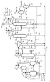
- FIG. 1 is a flowchart for explaining the method for producing acetic acid of the present invention.
- the continuous production process (or production apparatus) of acetic acid shown in the figure is to separate (1) carbonylation reaction step (reaction system or reactor) of methanol and (2) the reaction mixture into a volatile phase and a low volatility phase.
- Flash step flash evaporation step or flasher
- a first distillation step first distillation column or splitter column
- separation step for separating at least acetaldehyde from said first overhead, said separation step (4) the step of (5) condensing the first overhead to form a condensate (or the step of separating into two phases); and (6) (2) extracting acetaldehyde from the second overhead, and extracting an acetaldehyde-rich extract and a methyl iodide-rich raffinate; It includes an extraction step
- reaction step (1) methanol and carbon monoxide are continuously supplied to the reactor in a reaction medium containing a carbonylation catalyst system and water to carbonylate methanol to produce acetic acid.
- a liquid phase reaction system containing a reaction component and a metal catalyst component, carbon monoxide, hydrogen produced by the reaction, methane, carbon dioxide, and a vaporized low-boiling component (methyl iodide, produced And a gas phase system composed of such as acetic acid, methyl acetate, etc.) form an equilibrium state, and the carbonylation reaction of methanol proceeds.
- the reaction mixture is continuously introduced or supplied from this reactor (1) to one or more flashers (catalyst separation column or flash evaporation tank) (2), and the vapor component (gas phase) is withdrawn through the line 12 for heat exchange (Condenser) C1 to cool and condense, return the condensate to the reactor (1) through line 13, and supply non-condensed gas through line 14 to a scrubber unit (not shown) having an absorption processing unit There is. Part of the heat of reaction can be removed by returning the condensate to the reactor (1).
- flashers catalyst separation column or flash evaporation tank
- reaction heat may be removed by returning the non-condensed gas to the reactor (1), useful components (carbon monoxide and / or hydrogen, iodination) recovered from the non-condensed gas by the scrubber unit Methyl, methyl acetate etc.) may be recycled to the reactor (1).
- the carbonylation catalyst system usually comprises a metal catalyst (cobalt catalyst, rhodium catalyst, iridium catalyst etc.), a catalyst stabilizer or reaction promoter, and a cocatalyst.
- the metal catalysts can be used alone or in combination of two or more.
- Preferred metal catalysts are rhodium catalysts and iridium catalysts (especially rhodium catalysts).
- Metal catalysts include elemental metals, metal oxides (including complex oxides), hydroxides, iodides, carboxylates (such as acetates), inorganic acid salts (such as sulfates, nitrates, and phosphates), complexes It can also be used in the form of.
- the metal catalyst is preferably used in a soluble form (in the form of a complex etc.) in the liquid phase (reaction liquid).
- rhodium iodine complexes for example, RhI 3 , RhI 2 (CO) 4 ) ⁇ , [Rh (CO) 2 I 2 ] ⁇ , etc., rhodium carbonyl complexes and the like are preferable.
- the concentration of the metal catalyst is, for example, about 100 to 5000 ppm (by weight, hereinafter the same), preferably 200 to 3000 ppm, more preferably 300 to 2000 ppm, and particularly about 500 to 1500 ppm, based on the whole liquid phase in the reactor.
- the catalyst stabilizer or reaction accelerator may, for example, be a metal iodide capable of generating an iodine ion in the reaction solution, for example, an alkali metal iodide (lithium iodide, sodium iodide, potassium iodide etc.), among which Lithium iodide is preferred.
- an alkali metal iodide lithium iodide, sodium iodide, potassium iodide etc.
- These cocatalysts or promoters can be used alone or in combination of two or more.
- the concentration of the catalyst stabilizer or reaction accelerator is, for example, about 1 to 25% by weight, preferably 2 to 22% by weight, and more preferably about 3 to 20% by weight, based on the whole liquid phase in the reactor. .
- the concentration of iodide ion in the reaction system may be, for example, 0.05 to 2.5 mol / L, preferably 0.25 to 1.5 mol / L.
- Methyl iodide is used as the cocatalyst.
- concentration of methyl iodide is, for example, 1 to 30% by weight, preferably 5 to 25% by weight, more preferably 6 to 20% by weight (eg, 8 to 18% by weight) based on the whole liquid phase in the reactor. ) Degree.
- a preferred carbonylation catalyst system can consist of a rhodium catalyst and a metal iodide (lithium iodide) as a catalyst stabilizer and a methyl iodide cocatalyst.
- a catalyst mixture (catalyst liquid) containing a carbonylation catalyst system and water may be supplied to the reactor.
- the reaction medium usually contains produced acetic acid, methyl acetate produced by the reaction of produced acetic acid and raw material methanol, and water. Acetic acid also functions as a solvent.
- the reaction medium (or liquid phase) also usually contains unreacted starting material methanol.
- the content ratio of methyl acetate is 0.1 to 30% by weight, preferably 0.3 to 20% by weight, more preferably 0.5 to 10% by weight (for example, 0.5 to 6% by weight) based on the whole reaction solution. It may be a rate of degree.
- the concentration of water in the reaction medium may be low, and is, for example, 0.1 to 15% by weight, preferably 0.5 to 10% by weight, and more preferably 0.8 to It may be about 5% by weight (eg, 1 to 3% by weight), and may be about 1 to 10% by weight (eg, 2 to 5% by weight).
- the concentration of acetic acid may be, for example, about 30 to 90% by weight (eg, 35 to 85% by weight), preferably about 45 to 80% by weight, based on the whole liquid phase.
- the partial pressure of carbon monoxide in the reactor may be, for example, about 0.2 to 3 MPa, preferably about 0.4 to 1.5 MPa, in absolute pressure.
- hydrogen is generated by the reaction of carbon monoxide with water. This hydrogen enhances the catalytic activity. Therefore, hydrogen may be supplied to the reactor if necessary.
- the hydrogen partial pressure of the reaction system is, for example, 0.0005 to 0.25 MPa (for example, 0.001 to 0.2 MPa), preferably 0.005 to 0.15 MPa, and more preferably 0.01 to 0.05 in absolute pressure. It may be about 0.12 MPa.
- gaseous components including hydrogen, carbon monoxide, etc.
- carbon monoxide and / or hydrogen may be recycled to the reaction system, and useful from the off gas Condensed components may be recovered and recycled to the reaction system.
- the carbonylation reaction temperature may be, for example, about 150 to 250 ° C., preferably about 160 to 230 ° C., and more preferably about 170 to 220 ° C.
- the reaction pressure may be, for example, about 1.5 to 4 MPa in gauge pressure, including the partial pressure of by-products.
- the space-time yield of the target acetic acid in the reaction system may be, for example, about 5 to 50 mol / Lh, preferably about 8 to 40 mol / Lh, and more preferably about 10 to 30 mol / Lh.
- reaction crude liquid In the reaction mixture (reaction crude liquid), acetic acid, low boiling components having a boiling point lower than acetic acid or low boiling impurities (methyl iodide as a cocatalyst, methyl acetate, water, a side reaction product such as acetaldehyde), And high-boiling components or high-boiling impurities having a boiling point higher than that of acetic acid [metal catalyst components (such as rhodium catalysts), lithium iodide as a catalyst stabilizer, C 3-12 alkanecarboxylic acids such as propionic acid, etc.] .
- metal catalyst components such as rhodium catalysts
- lithium iodide as a catalyst stabilizer
- C 3-12 alkanecarboxylic acids such as propionic acid, etc.
- aldehydes such as butyraldehyde, crotonaldehyde, 2-ethyl crotonaldehyde, 2-ethylbutyraldehyde, etc. ketones such as acetone, methyl ethyl ketone etc.
- Aldol condensation products; C 2-12 alkyl iodides such as ethyl iodide, propyl iodide, butyl iodide, pentyl iodide, hexyl iodide and the like are also formed.
- 3-hydroxyalkanal such as 3-hydroxybutanal
- C 3-12 alkanecarboxylic acid such as formic acid, propionic acid, butanoic acid, hexanoic acid, heptanoic acid, octanoic acid
- butyl alcohol 2-ethyl butyl C 3-12 alkyl alcohol such as alcohol
- methanol or ester of the above alkyl alcohol with acetic acid or the above carboxylic acid methanol and / or ethers of the above alkyl alcohol (dialkyl ethers such as dimethyl ether): methane and carbon number It also produces two or more hydrocarbons (eg, C 2-12 alkanes).
- acetaldehyde and by-products derived from acetaldehyde form permanganic acid reducing substances (PRCs). Therefore, it is preferable to separate and remove acetaldehyde and PRC, which are main components of by-products, from the reaction mixture, and useful components (eg, methyl iodide and the like) are recovered from the process stream and effectively utilized.
- PRCs permanganic acid reducing substances
- the concentration of acetaldehyde in the reactor is reduced by recycling the process stream in which the acetaldehyde concentration is reduced or from which acetaldehyde has been removed to the reactor.
- the formation of acetaldehyde-derived by-products can also be significantly suppressed.
- the acetaldehyde concentration in the liquid phase of the reactor may be 400 ppm or less (eg, 0 or detection limit to 300 ppm), preferably 10 to 250 ppm (eg, about 20 to 200 ppm).
- the concentration of the alkyl iodide having two or more carbon atoms such as hexyl iodide may be, for example, about 0.1 ppb to 1 ppm (eg, 0.5 to 500 ppb), preferably about 1 to 100 ppb.
- the concentration of dimethyl ether (DME) may be, for example, about 0.1 to 1000 ppm, preferably about 1 to 500 ppm (eg, 2 to 300 ppm), and more preferably about 3 to 200 ppm (eg, 5 to 100 ppm).
- the reaction system is an exothermic reaction system with heat generation, and the reaction temperature may be controlled by a heat removal unit or a cooling unit (jacket or the like).
- Flash evaporation step (2) the reaction mixture continuously supplied from the reactor (1) through the line 11 is flash evaporated with a flasher (flash evaporation tank) to produce acetic acid, methyl iodide, It is separated into a volatile phase (2A) including acetaldehyde, methyl acetate, water and the like, and a low volatility phase (2B) including a rhodium catalyst and lithium iodide.
- the low volatility phase (2B) is cooled by the cooler C3 and recycled to the reactor of the reaction step (1) through the recycle line 21 to remove part of the reaction heat.
- At least a portion of the volatile phase (2A) is fed through line 22 to the distillation column of the first distillation step (3).
- a part of the volatile phase (2A) is cooled and condensed by the condenser C2 in the line 23, the condensate is stored in the hold tank 25 through the line 24, and the condensate is reacted through the line 26 (reactor (reactor (1), and non-condensed gas is supplied through line 27 to a scrubber unit (not shown) having an absorption processing unit.
- a part of volatile phase (2A) is cooled by condenser C2 and condensed, and the cooled substance (condensed liquid and / or non-condensed component) from condenser C2 is supplied to separation step (5), decanter Within (5), it may be separated into two phases together with the overhead (3A) from the first distillation step (splitter column) (3).
- Some volatile phase (2A) may be fed to the second distillation step (6) directly or indirectly via a separation step (5) without condensation, one or more
- the aqueous phase or organic phase (at least the aqueous phase) separated by cooling and condensing in the condenser C2 is separated into two phases, directly or indirectly via the separation step (5), the second phase You may use for a distillation process (6).
- part of the volatile phase (2A) is condensed if necessary (further separated if necessary), and combined with the condensate in the separation step (5) to form a second distillation step ( You may use for 6).
- the catalyst component may be separated from the low volatility phase (2B) in one or more steps and recycled to the reaction step (1) for reuse.
- the flash evaporation separates the reaction mixture from the vapor component and the liquid component by heating the reaction mixture under reduced pressure, isothermal flash for reducing the pressure without heating the reaction mixture, or a combination of these flash conditions.
- You may Flash evaporation is carried out, for example, at a temperature of about 80 to 250 ° C., preferably about 120 to 180 ° C., a pressure (gauge pressure) of 0.01 to 1 MPa, preferably 0.05 to 0.5 MPa, and more preferably 0.1 to 0. It may be about 2 MPa.
- Second distillation step (splitter column or distillation column)
- the volatile phase (2A) is distilled from the top of the column or from the upper portion of the column through the distillation line 33 (the overhead gas, low boiling point stream) (3A), an acetic acid stream (3B) which is side-cut through line 36, mainly containing acetic acid, and a bottoms liquid or a bottoms liquid stream which flows out from the bottom of the column through the bottom line 31 It is separated into high boiling point fractions or high boiling point components (3C).
- the first overhead (3A) corresponds to the mixture (3A) and contains at least permanganate reducing substances (PRCs) and methyl iodide, and the PRCs contain at least by-product acetaldehyde . Furthermore, the first overhead (3A) usually contains methyl acetate, and further acetic acid, water, dimethyl ether, byproducts derived from acetaldehyde (eg, aldehydes such as crotonaldehyde and butyraldehyde, iodinated C 2-- In many cases, it contains 12 alkyl, a derivative from acetaldehyde such as C 3-12 alkanecarboxylic acid, C 2-12 alkane) and the like, and in many cases, it contains methanol.
- acetaldehyde eg, aldehydes such as crotonaldehyde and butyraldehyde, iodinated C 2--
- acetaldehyde eg,
- An acetic acid stream or a sidecut stream (3B) is further supplied to a purification step such as a distillation column (not shown) in order to remove dehydration and / or high-boiling components and the like to produce purified high-purity acetic acid.
- This purification step may include an ion exchange treatment unit on the downstream side of the distillation column in order to remove an iodine component (such as hydrogen iodide or alkyl iodide).
- the liquid stream (3C) usually contains at least water and acetic acid, and often contains methanol, methyl iodide, methyl acetate, propionic acid and the like.
- the metal catalyst component may be mixed by entrainment.
- a part of the liquid stream (3C) may be recycled to the flasher (flash evaporation tank) (2) through the line 32, and a part or all of the liquid stream (3C) may be recycled through the lines 31 and 100.
- (Reactor) (1) may be recycled. Note that part or all of the liquid stream (3C) may be discharged through the line 31.
- a distillation column (splitter column) (3) a plate column, a packed column, etc. can be used.
- the bottom temperature may be, for example, about 60 to 200 ° C., preferably about 100 to 160 ° C.
- the pressure (gauge pressure) is, for example, about 0.05 to 0.5 MPa, preferably It may be about 0.08 to 0.4 MPa, more preferably about 0.1 to 0.3 MPa.
- the theoretical plate of the distillation column may be, for example, about 2 to 100 plates, preferably about 8 to 30 plates.
- the reflux ratio in the distillation column is total reflux (total reflux means that all the condensate on the top of the distillation column is recycled to the top of the distillation column) or, for example, 1 to 1000, preferably 10 to It may be around 100.
- the volatile phase (2A) is distilled to form a first overhead (3A) rich in at least one low-boiling component selected from methyl iodide and acetaldehyde; It may be separated into a crude acetic acid stream (3B) which is rich in acetic acid from the cut, and the bottoms liquid stream (3C) does not necessarily have to be separated.
- the liquid stream (3C) may be discharged, and part or all of the liquid stream (3C) may be returned to the splitter column (2) and recycled to the reactor of the reaction step (1).
- the first overhead (3A) may be subjected to the second distillation step (6) in gaseous form as a mixture (3A) without undergoing the condensation and separation step (5), the condensed condensate May be subjected to the second distillation step (6) without separation.
- a mixture (3A) in which methyl iodide, particularly methyl iodide and PRCs are concentrated by separation step (5) of separation step (4) described later Is generating. That is, the mixture (3A) may be any of the first overhead (3A), the condensate of the first overhead (3A), and the upper phase and / or the lower phase from which the condensate is separated.
- Mixture (3A) often contains water, acetic acid, methyl iodide, methyl acetate, dimethyl ether, at least one C 2-12 alkyl iodide and at least one permanganate reducing compound (PRC), methanol In many cases.
- Preferred mixtures (3A) are condensates, in particular the separated upper and / or lower phases (or a mixture of upper and lower phases).
- acetaldehyde is concentrated in the upper phase (water phase)
- acetaldehyde is also contained in the lower phase (organic phase)
- the dimethyl ether also has high vapor pressure and high affinity or miscibility with water, methyl iodide, etc. It is concentrated. Therefore, even if the upper phase, the lower phase or the mixture of the upper and lower phases as mixture (3A) is distilled in the second distillation step (2), the pressure in the column becomes excessively high in the present invention. You can control the
- the first overhead (3A) contains impurities and useful components such as PRCs, methyl iodide, methyl acetate, dimethyl ether, methanol and the like. Therefore, in the separation step (4), at least acetaldehyde is separated from the first overhead (3A). In particular, the first overhead (3A) is separated into an acetaldehyde rich stream and a useful methyl iodide rich stream.
- the separation step (4) comprises (5) condensing the first overhead (3A) to form a condensate, and separating the condensate into two phases of an upper aqueous phase and a lower organic phase.
- Separation step (a step of forming a condensate as a mixture, an upper phase and / or a lower phase) (a separation step), (6) at least one of the condensed liquid (the separated upper phase and / or the lower phase)
- a second distillation step (aldehyde separation step) for separating the pressure in the distillation column with controlled pressure into a second overhead rich in acetaldehyde and methyl iodide and a bottom or bottom stream, 7) extracting the acetaldehyde from the second overhead from this step (6) and separating it into an acetaldehyde rich extract and a methyl iodide rich raffinate (extraction step); Distilling the extract, Al A fourth overhead containing hydrate, fourth distillation step (alde
- the liquid separation process (5) Liquid separation process
- the first overhead (3A) from the line 33 is cooled and condensed by a heat exchanger (capacitor) C4 and enriched in methyl iodide, water, methyl acetate
- the condensation step (11a) to form a condensate containing water, etc.
- the separation step (decanter) (5) the upper phase (aqueous phase) rich in acetaldehyde and the lower phase rich in methyl iodide And (ii) separating the two phases with the organic phase), and subjecting the separated upper phase (aqueous phase) and / or the lower phase (organic phase) to a second distillation step (6) ing.
- the aqueous phase is rich in acetaldehyde and forms an upper or light phase containing methyl acetate, acetic acid, methyl iodide etc.
- the lower phase is rich in methyl iodide, an organic phase or heavy containing methyl acetate, acetic acid, water etc.
- the non-condensed gas not condensed in the condensation step of the heat exchanger (condenser) C4 is rich in methyl iodide and contains methyl acetate, carbon monoxide and the like. Therefore, non-condensed gas may be supplied through line 35 to a scrubber unit (not shown) having an absorption processing unit.
- a portion of the condensate (upper phase in the decanter (5)) is refluxed to the first distillation column (splitter column) (3) via the reflux line 42, and the lower phase (methyl iodide rich organic)
- the lower phase methyl iodide rich organic
- a portion of the phase or heavy phase is recycled to reactor (1) through lines 41,100.
- a part of the upper phase (water phase or light phase rich in acetaldehyde) separated in the decanter (5) may be recycled to the reactor (1).
- the first overhead (3A) is sequentially cooled by a plurality of capacitors (a plurality of capacitors whose cooling temperatures are sequentially lowered) to generate condensate whose temperature is sequentially decreased
- the first stage Acetaldehyde is present at a higher concentration in the condensate from the condenser downstream than the process liquid (condensate) condensed by the condenser. Therefore, the concentrate having acetaldehyde concentrated to a high concentration may be subjected to the second distillation step (6) to separate acetaldehyde.
- a plurality of capacitors useful components of the off gas can be effectively utilized.
- a plurality of capacitors C4 whose cooling temperatures sequentially decrease in the downstream direction are provided in the line 33, and an off-gas is introduced between the plurality of capacitors C4 and the upstream side of the plurality of capacitors C4 for cooling.
- the off gas can be separated into the condensed liquid and the non-condensed gas without being separated by the scrubber unit etc.
- the non-condensed gas is supplied to the scrubbing equipment (scrubber unit) for processing, and a part of the condensed liquid is reacted
- scrubbing equipment scrubber unit
- useful components in the off gas can be effectively utilized for the reaction, and aldehyde can be effectively separated.
- the off gas is not particularly limited as long as it is an off gas generated from an acetic acid production process, and, for example, the off gas 14 from the reactor (1), the off gas 27 from the flasher (2), the second distillation step described later (6 ), The off gas from the separation step (5), the off gas from the extraction step (7) (eg, the off gas from the extractive distillation step), the off gas from the fourth distillation step, etc. Good.
- the offgas from at least the second distillation step (6) is used as the offgas.
- the condensate may be recycled to at least one unit of the reactor (1) and the distillation column of the distillation step (the first distillation column (3) and / or the second distillation column (6)), Usually, it is often recycled to both the reactor (1) and the second distillation column (6).
- a buffer tank or hold tank may be used to store (or hold) the fuel in order to suppress flow rate fluctuations and the like of the process flow.
- At least one of the acetaldehyde-rich upper phase (aqueous phase or light phase) separated in the decanter (5) and the methyl iodide-rich lower phase (organic phase or heavy phase) is subjected to the second distillation It may be supplied to the step (aldehyde separation step) (6) and / or the reaction step (1).
- the upper phase (aqueous phase or light phase) may be supplied instead of the lower phase (organic phase or heavy phase).
- the lower phase (organic phase or heavy phase) may be recycled instead of the upper phase (aqueous phase or light phase), and both the upper phase and the lower phase may be recycled. It is also good.
- Second distillation step (aldehyde separation step)
- the condensate condensed in the separation step (5) is supplied to a second distillation step or distillation column (6), and in the second distillation column (6), the condensate is distilled to obtain methyl iodide and PRC Acetaldehyde-rich second overhead (5A) (6A) and a bottom stream (5B) (6B) rich in methyl iodide, including methyl acetate and the like.
- the aqueous phase or light phase (rich in acetaldehyde) and / or the organic phase or heavy phase (rich in methyl iodide, methyl acetate) in the condensate condensed in the separation step (5) Etc.) is supplied to the second distillation step or distillation column (6). More specifically, of the condensate condensed in the separation step (5), a portion of the acetaldehyde-rich aqueous phase or light phase is supplied to the second distillation step or distillation column (6) through the line 43. Part of the aqueous phase is recycled via line 44 to the reactor (1).
- the organic phase or heavy phase which is rich in methyl iodide and contains methyl acetate and the like is supplied to the second distillation step or distillation column (6) through line 45.
- the second distillation step (6) at least a portion of at least one of the aqueous phase and the organic phase may be distilled, and at least a portion of the aqueous phase or at least a portion of the organic phase may be distilled.
- at least a portion of both the aqueous phase and the organic phase may be distilled.
- the second distillation step (6) may be provided with at least one distillation column, and in this example, the second distillation step (6) includes a plurality of distillation columns (in this example, two distillation columns (6a) ) (6b)). That is, the condensate (in this example, at least a portion of at least one of the aqueous phase and the organic phase in this example) supplied to the second distillation column (6a) through the lines 43 and 45 is distilled from the top by distillation. Separated into overhead (5A) from line 55 and bottom stream (5B) from bottom line 51 which is rich in methyl iodide and contains methyl acetate, acetic acid, water etc.
- overhead (5A) from line 55 and bottom stream (5B) from bottom line 51 which is rich in methyl iodide and contains methyl acetate, acetic acid, water etc.
- the condensate is distilled to the overhead (6A) from line 62 and the bottom stream (6B) from line 61 which is rich in methyl iodide and contains methyl acetate etc.
- the overhead (6A) is cooled and condensed by condenser C6 in line 62, the condensate is stored in hold tank 65 through line 64, and a portion of the condensate is collected in the third distillation column (through reflux line 66) Refluxing to 6b), part of the methyl iodide and acetaldehyde rich condensate is fed to the extraction step (7).
- the non-condensed gas not condensed by the condenser C6 is also supplied to a scrubber unit having an absorption processing unit and / or a membrane separation facility (a membrane separation unit) (not shown) through lines 69 and 71. Good.
- a scrubber unit having an absorption processing unit and / or a membrane separation facility (a membrane separation unit) (not shown) through lines 69 and 71.
- the plurality of condensers C4 sequentially cooled as described above are provided, and the non-condensed gas 71 is used as it is. It may be introduced between the upstream side or a plurality of condensers, and useful components may be recovered, recycled to the reaction step and / or the distillation step, and effectively used for reactions and the like.
- the non-condensed gas 71 may be recycled to the reaction step (1) and / or the distillation step via a line including at least one condenser C4 and a recycle line, and the distillation step is a first distillation step It may be at least one distillation step of 3) and the second distillation step (6).
- the non-condensed gas 71 may be directly recycled to the second distillation step (6) via the line including the condenser C4 of the first distillation step (3) and the recycle line, Through 5), it may be indirectly recycled to the second distillation step (6).
- the second distillation column (6a) and / or the third distillation column (6b) may be recycled.
- a portion of the bottom stream (5B) from the second distillation column (6a) may be recycled to the reactor (1) through lines 52, 100, a portion of the bottom stream (5B) from line 51 It may be fed to the decanter (5) through a branching line 53. Further, a portion of the bottom stream (5B) may be refluxed to the third distillation column (6b) through the line 54 and the reflux line 66 branched from the line 51. Also, the bottom stream (6B) from the third distillation column (6b) may be recycled to the reactor (1) through lines 61,100.
- low boiling point components such as dimethyl ether having a high vapor pressure may be by-produced. Therefore, at the top of the third distillation column (6b), low-boiling components with high vapor pressure (methyl iodide, acetaldehyde, dimethyl ether etc.) are gradually concentrated along with distillation (concentration of low-boiling components with high vapor pressure) May cause pressure rise.
- the pressure control unit PC (68) is disposed at the top of the third distillation column (6b), and the pressure in the third distillation column (6b) (in this example, the overhead (6A)
- the pressure of the line 62) is detected by a pressure sensor, and when the detected value becomes larger than the reference value (the reference value which may have a predetermined threshold), the pressure control unit PC (68)
- the control signal of the control amount is given to the pressure control valve 70 (the valve 70 in the line 71), and the valve is opened to allow the noncondensed gas to flow out from the line 71 to maintain a predetermined pressure.
- the pressure control unit PC (68) gives a control signal to the pressure control valve 70, and the valve is closed. That is, the flow rate of non-condensed gas (overhead) is adjusted, and the pressure in the third distillation column (6b) is controlled.
- nitrogen gas N 2 is introduced through the line 72 to maintain a predetermined pressure.
- a small amount of nitrogen gas may be constantly supplied from the line 72 to open the control valve 70 at an opening degree suitable for control, to improve the response and / or controllability of the control valve 70.
- the nitrogen gas flow rate (kg / H) is 1% or less (eg, 0.0001 to 1%), preferably 0.1% or less (eg, 0.001 to 0.05%) of the flow rate of line 59. It may be.
- the second distillation step (aldehyde separation step) (6) does not have to include a plurality of distillation columns, and may have a single distillation column.
- the mixture (3A) for example, a condensate, or the upper phase and / or the lower phase generated in the liquid separation step (5) may be distilled.
- the upper phase contains more acetaldehyde than the lower phase. Therefore, instead of the lower phase, the upper phase generated in the separation step (5) may be distilled, and at least a part of the upper phase (for example, at least a part of the upper phase and at least a part of the lower phase ) May be distilled.
- the lower phase produced in the separation step (5) is rich in methyl iodide and also contains dimethyl ether, methyl acetate, methanol, water and the like. Therefore, when at least the lower phase is distilled in the second distillation step (aldehyde separation step) (6), the pressure in the column may rise, but in the present invention, as described above, the pressure rise in the column It can be effectively suppressed. Therefore, in the present invention, at least a part (part or all) of the lower phase (organic phase) may be distilled in the second distillation step (aldehyde separation step) (6).
- the first overhead may be distilled while controlling the pressure of the distillation column; The step of continuously distilling in the column), controlling the pressure in at least one distillation column (upstream, middle and / or downstream distillation column) while controlling the first overhead or mixture (3A) It may be distilled.
- the first overhead may be distilled while controlling the pressure of the distillation column at least at the downstream side (the most downstream side) of the distillation column where low boiling point components having high vapor pressure are easily concentrated .
- the flow rate of non-condensed gas (overhead) may be adjusted to control the pressure, and a plurality of distillation columns can be controlled.
- the amount of non-condensed gas forms an outlet communicating with the gas phase portion of the hold tank 65 disposed downstream of the condenser C6, and the pressure and / or flow rate of this outlet May be detected and pressure controlled.
- a pressure sensor may be attached to the top of the distillation column for pressure control.
- the amount of condensed liquid and non-condensable gas containing components that can not be condensed at that temperature may be controlled to adjust the amount of gas discharged from the line 71 for pressure control.
- the concentration of acetaldehyde AD is It is lower in the off-gas than in comparison. Therefore, in this process, the acetaldehyde removal efficiency (deAD efficiency) is hardly reduced even if the off gas is discharged out of the system. Moreover, since the pressure control unit can suppress the flow rate of the process flow and / or the pressure fluctuation, acetaldehyde can be stably removed, and the acetaldehyde removal efficiency can be improved.
- the condensate is subjected to the extraction step (7), and at least one component selected from methyl iodide, methyl acetate, dimethyl ether, water and carbon monoxide is recovered from the (10) off gas to directly or indirectly Recycling to the reaction step (1) and / or the distillation step (the first distillation step (3) and / or the second distillation step (6)), it is effective for the reaction without discharging the useful components of the off gas While being usable, separation efficiency of PRCs such as acetaldehyde can be improved.
- PRCs such as acetaldehyde
- a plate column, a packed column, etc. can be utilized as a distillation column of a 2nd distillation process (6).
- the pressure (gauge pressure) in the distillation column in the second distillation step is, for example, about 0.01 to 0.6 MPa, preferably about 0.13 to 0.4 MPa, and more preferably about 0.15 to 0.35 MPa It may be.
- the pressure may be selected in an advantageous condition in terms of cost in consideration of the separation efficiency, the amount of energy used, the equipment cost and the like, and the pressure may be operated so as to make the value of the selected pressure constant.
- the operating pressure changes, the boiling point of the components to be separated by distillation changes, which causes a disadvantage in the desired separation by distillation. As a matter of course, it is not safe to operate at a pressure exceeding the pressure resistance condition of the equipment.
- the theoretical plate of the distillation column may be, for example, about 10 to 150 plates, preferably about 20 to 90 plates.
- the reflux ratio in the distillation column may be total reflux or, for example, about 1 to 1000, preferably about 50 to 400.
- nitrogen gas but also off gas (off gas including carbon monoxide, carbon dioxide, nitrogen gas, etc.) and inert gas (e.g., argon etc.) are introduced from the above-mentioned line 72 from the above-mentioned scrubber unit. It is also good.
- off gas including carbon monoxide, carbon dioxide, nitrogen gas, etc.
- inert gas e.g., argon etc.
- the condensate from the line 67 is extracted with water by a water extraction unit (water extractor) and separated, and the methyl iodide rich organic phase (raffinate) and acetaldehyde rich It is separated into an aqueous phase (extract).
- the extraction step (7) includes two water extraction units (water extractors). That is, in the first water extraction unit (water extractor) (8), the condensed liquid (cooled) from the line 67 is used with water (for example, cooled water) from a predetermined line (not shown).
- the first raffinate (7B) is extracted with water and separated to separate it into a second raffinate (8B) and a second extract (8A). Therefore, the acetaldehyde concentration of the second raffinate (8B) is extremely reduced, and a portion of the second raffinate (8B) is recycled to the reactor (1) through the lines 91, 92, and 100. A portion of the raffinate (8B) is recycled through line 93 to the second distillation step (6).
- a part of the second raffinate (8B) is supplied to the distillation column (6b) on the downstream side of the second distillation step (aldehyde separation step) (6).
- the acetaldehyde-rich first and second extracts (7A) and (8A) may be distilled in the distillation column (not shown) of the subsequent fourth distillation step (8) to recover water.
- the first and second extracts may be drained or drained without distillation.
- At least a part of the raffinate may be recycled to the reaction step (1) and / or the distillation step (the first distillation step (3) and / or the second distillation step (6)).
- the raffinate can be recycled to the reaction step (1) and / or the distillation step (6), and at least a portion of the raffinate may be recycled to at least the reactor.
- a portion may be recycled to the distillation column of the second distillation step (6).
- at least a portion of the raffinate may be recycled to the distillation column of the second distillation step (6) and the recycled raffinate may be distilled together with said mixture (3A).
- the pressure control unit can suppress fluctuations in the pressure in the column, stably and safely. It can operate.
- a part of the second raffinate (8B) may be any distillation column, for example, the second distillation. It may be fed to column (6a) and / or a third distillation column (6b).
- a part of the second raffinate (8B) may be supplied to the distillation column equipped with a pressure control unit, for example, the downstream distillation column.
- the second overhead (5A) (6A) may be extracted intermittently (stepwise) or continuously in water.
- Water extraction may be performed in a single or multiple extractors.
- the extractor for example, a combination of a mixer and a settler, a combination of a static mixer and a decanter, a RDC (rotated disk contactor), a Karr tower, a spray tower, a packed tower, a perforated plate tower, a baffle plate tower, a pulsation tower, etc.
- the extractor (extraction column) may be a single-stage (single-stage) extractor which can be mixed and extracted with water and can be separated, and the single-stage extractor may be arranged in cascade.
- water may be extracted in a plurality of theoretical plates.
- it may be a multi-stage (multi-stage) extraction device which sequentially extracts using a plurality of extractors (each extractor of the theoretical stage 1).
- it may be a multi-stage extraction apparatus in which a plurality of extractors are arranged in one apparatus, for example, a single stage having a theoretical stage (theoretical stage corresponding to multi-stage extraction) equivalent to a multistage (multistage) extraction apparatus It may be one extraction device.
- the extraction may be performed by any of a batch system and a continuous system, and may be either a cocurrent extraction or a countercurrent extraction.
- the number of theoretical plates for water extraction is not limited to one, and may be about 0.5 to 5 stages.
- water from outside the process may be used, and water in the process may be reused for water extraction.
- the water extraction temperature may be about ⁇ 10 to 70 ° C., preferably about 5 to 60 ° C., and more preferably about 10 to 50 ° C.
- the water extraction may be carried out under normal pressure or under pressure, and may be carried out under gauge pressure, for example, at about 0.1 to 0.5 MPa, preferably about 0.15 to 0.4 MPa.
- a water extraction distillation column may be used instead of the water extraction unit (water extraction unit).
- the condensate is supplied to the water extractive distillation column and the extractant (water) from the upper part of the distillation column is supplied, and the methyl iodide rich raffinate from the top or the upper part is Water extract (extract from which acetaldehyde is extracted).
- the temperature of the extractant (water) may be, for example, 0 to 60 ° C., preferably 10 to 50 ° C., more preferably 20 to 40 ° C., and normal temperature (eg, 15 to 25 ° C.) Degree).
- the extractant (water) may be added warm or heated or in the form of steam.
- the internal temperature of the water extraction distillation column depends on the pressure, and the top temperature at normal pressure may be, for example, about 10 to 120 ° C., preferably about 20 to 90 ° C., and the bottom temperature is For example, it may be about 15 to 150 ° C., preferably about 25 to 120 ° C., and the top pressure is, for example, about 0.1 to 0.5 MPa, preferably 0.2 to 0.4 MPa in absolute pressure. It may be an extent.
- the theoretical plate of the distillation column may be, for example, about 0.5 to 30 plates, preferably about 2 to 20 plates.
- the reflux ratio in the distillation column may be, for example, about 0.01 to 500, preferably about 0.5 to 50, and more preferably about 2 to 20.
- the second overhead condensate is subjected to water extraction with the water extraction distillation and / or the water extractor, and the extract is supplied to the fourth distillation step (8). And a step of recycling the raffinate to the reaction step (1) and the distillation step (6).
- the non-condensed gas (off gas) generated from the extraction step (7) for example, the gas phase gas from the water extraction unit (water extractor) (8) (9), the non-condensed gas generated by water extraction distillation,
- a plurality of condensers are used to recover useful components, instead of the scrubber unit and / or the membrane separation unit, or together with the scrubber unit and / or the membrane separation unit, the reaction process and / or the distillation process ( It may be recycled to the first distillation step (3) and / or the second distillation step (6)), and may be effectively utilized for reactions and the like.
- the fourth overhead is cooled and condensed by one or more condensers, and is separated into a condensate containing water, methyl iodide, acetaldehyde and the like, and a non-condensed gas containing acetaldehyde.
- Non-condensed gas may be supplied to a scrubber unit (not shown) having an absorption processing unit, as described above, instead of or in combination with the scrubber unit and / or the membrane separation unit.
- a plurality of condensers C4 sequentially cooled may be provided, and the non-condensed gas may be introduced as it is between the upstream side or the plurality of condensers to recover useful components and effectively utilize it for reactions and the like.
- a distillation column of the fourth distillation step (8) a plate column, a packed column, or the like can be used as a distillation column of the fourth distillation step (8).
- the bottom temperature may be, for example, about 40 to 180 ° C., preferably about 80 to 160 ° C.
- the pressure gauge pressure
- the pressure may be, for example, about 0.0 to 0
- the pressure may be about 0.5 MPa, preferably about 0.1 to 0.3 MPa, and more preferably about 0.12 to 0.25 MPa.
- the theoretical plate of the distillation column may be, for example, about 1 to 30 plates, preferably about 2 to 10 plates.
- the reflux ratio in the distillation column may be total reflux or, for example, about 0.1 to 100, preferably about 2 to 20.
- Off-gas treatment step 10 The non-condensed gas (off-gas) generated from the above process may be discharged out of the system, but the non-condensed gas (off-gas) also includes methyl iodide, methyl acetate, dimethyl ether, water and monoxide. It contains useful ingredients such as carbon. Therefore, in the off-gas treatment step (10), non-condensed gas (off-gas) is treated, useful components are separated or recovered, and reaction step (1) and / or distillation step (first distillation step) directly or indirectly. It is preferable to recycle to (3) and / or the 2nd distillation process (6)), and to utilize effectively.
- the non-condensed gas is at least one condenser, in particular, a plurality of condensers whose condensation temperature is lowered in the downstream direction (for example, a plurality of condensers provided in line 33 of the first overhead (3A)
- the condenser C4 of the above or between condensers, cooled and condensed, and the condensed component (condensed liquid) is subjected to the reaction step (1) and / or the distillation step (first distillation step (3) and / or Alternatively, it may be recycled to the second distillation column (6)).
- non-condensed gas is recycled to the reaction step (1) and / or the distillation step (the first distillation step (3) and / or the second distillation column (6)) via at least one condenser. It is also good.
- the non-condensable gas (off gas) is produced from the above process, for example, non-condensable gas (off gas rich in carbon monoxide and methyl iodide) 14 from the reactor (1), flasher (2) Non-condensable gas (off gas rich in acetic acid, methyl iodide and methyl acetate) 27, non-condensable gas 35 not condensed by the condenser C4 in the first distillation step (3) (and non-liquefied component in the decanter (5)) Or non-condensed gas (off gas) 60, 71 from the second distillation step (6) (off gas from the extraction step (7), if necessary).
- the non-condensed gas often includes at least the non-condensed gas (off gas) 60, 71 from the
- the non-condensed gas is directly fed to at least one of the first distillation step (3) and the second distillation step (6) via the at least one condenser (one or more condensers) C4. It may be recycled, or may be indirectly recycled to at least one of the first distillation step (3) and the second distillation step (6) (for example, indirectly via the decanter (5) May be recycled to the first distillation step (3) and / or the second distillation column (6a)). In the second distillation step (6), the second distillation column (6a) and / or the third distillation column (6b) may be recycled.
- non-condensed gas may be treated by a scrubber unit (or scrubbing equipment) having an absorption treatment unit. More specifically, the non-condensed gas (off gas) is absorbed under pressure into the absorption solvent of the absorption tower, and at least one component selected from methyl iodide, methyl acetate, dimethyl ether, water and carbon monoxide is absorbed. And may be recycled to the reaction step (1) and / or the distillation step (the first distillation step (3) and / or the second distillation step (6)).
- useful components can be effectively used in the reaction system (for example, components such as DME are used as an acetic acid raw material Possible to reduce the loss of useful components; by recycling to the second distillation step (6), the separation efficiency of impurities such as acetaldehyde can be improved and the pressure in the distillation column (6) can be controlled. Also, by recycling useful components from non-condensed gas (off gas) to the first distillation step (3), for example, upstream of the first distillation column (3) or at least one condenser C4, the decanter (5 Can improve the liquid separation in
- the off gas from the extraction step (7) is scrubbed in contact with an absorbing solvent (eg, acetic acid, etc.) in the absorption tower, with the first overhead stream rich in carbon monoxide, hydrogen, carbon dioxide and nitrogen.
- an absorbing solvent eg, acetic acid, etc.
- the carbon monoxide rich first overhead stream may be recycled to the reactor (1) and / or the flasher (2).
- the bottom acetic acid stream is distilled and stripped in a stripping column, and a second overhead stream rich in methyl iodide and acetic acid (also containing dimethyl ether, methanol, methyl acetate, acetaldehyde, etc.), acetic acid, acetic acid It can be separated into a methyl and water rich bottom acetic acid stream.
- methyl iodide and acetic acid also containing dimethyl ether, methanol, methyl acetate, acetaldehyde, etc.
- the second overhead stream is cooled and condensed by a condenser, and the non-condensed gas (a stream rich in methyl iodide and carbon monoxide and also containing dimethyl ether, methyl acetate, etc.) is reacted directly or indirectly (step 1) and / or may be recycled to the distillation step (first distillation step (3) and / or second distillation step (6)), and the condensate (rich in methyl iodide, acetic acid and methyl acetate, dimethyl ether) (A stream containing water, etc.) directly or indirectly via a hold tank 25, a condenser C4, a decanter (5) or the like in the reaction step (1) and / or the distillation step (first distillation step (3) and And / or may be recycled to the second distillation step (6)).
- the non-condensed gas a stream rich in methyl iodide and carbon monoxide and also containing dimethyl ether, methyl acetate, etc.
- the pressure control unit 68 can suppress the pressure rise in the distillation column of 2nd distillation process (6).
- the off-gas can be absorbed with an absorbing solvent and separated into a stream rich in carbon monoxide and a stream rich in acetic acid, methyl iodide and methyl acetate.
- the non-condensed gas 14 from the reactor (1) may be scrubbed with the absorbing solvent in the high pressure absorption tower, and the non-condensed gas 27 from the flasher (2) and the condenser of the first distillation step (3)
- the off gas from 9) may be scrubbed with the absorbing solvent in a low pressure absorber.
- the flow rate of non-condensed gas with respect to the absorption solvent is, for example, about 1/100 to 1000/1, preferably about 1/10 to 100/1, and more preferably about 1/1 to 50/1, based on weight. Or about 5/1 to 30/1.
- the temperature of the absorbing solvent may be, for example, about 10 to 70 ° C., preferably about 20 to 60 ° C., and more preferably about 30 to 55 ° C.
- the temperature in the column of the high pressure absorption column is not particularly limited, and the column top temperature may be, for example, about 10 to 75 ° C., preferably 20 to 60 ° C., and more preferably about 30 to 55 ° C.
- the pressure (gauge pressure) of the high pressure absorber may be, for example, about 0.5 to 5 MPa, preferably 1 to 4 MPa, and more preferably about 2 to 3.5 MPa (eg, 2.5 to 3 MPa).
- the flow rate of the non-condensed gas with respect to the absorbing solvent is, for example, 1/100 to 1000/1, preferably 1/10 to 100/1, more preferably 1/4 to 30/1, on a weight basis. It may be about 2/1 to 10/1.
- the temperature of the absorbing solvent may be, for example, about 0 to 60 ° C., preferably about 10 to 50 ° C., and more preferably about 20 to 40 ° C.
- the temperature in the low pressure absorber is not particularly limited, and the temperature at the top of the column may be, for example, about 10 to 50 ° C., preferably about 15 to 40 ° C., and more preferably about 20 to 30 ° C.
- the pressure (gauge pressure) of the low pressure absorber may be, for example, about 0.0 to 0.3 MPa (eg, 0.0 to 0.25 MPa), preferably about 0.1 to 0.2 MPa.
- the temperature in the column of the stripping column (stripping column) is not particularly limited, and the column top temperature may be, for example, about 50 to 150 ° C., preferably 70 to 130 ° C., and more preferably about 90 to 120 ° C.
- the column bottom temperature may be, for example, about 75 to 200 ° C., preferably about 100 to 180 ° C., and more preferably about 120 to 160 ° C.
- the pressure (gauge pressure) of the stripping column (stripping column) is, for example, about 0.0 to 0.3 MPa (for example, 0.0 to 0.25 MPa), preferably about 0.0 to 0.2 MPa. It is also good.
- As an absorption solvent methanol may be used instead of or together with acetic acid.
- the process stream (the volatile phase and / or the process stream from which acetaldehyde has been removed from the subsequent process stream) formed in the separation step and having a reduced concentration of acetaldehyde is recycled to the reactor It is also good.
- the concentration of acetaldehyde in the reaction medium in the reactor is 400 ppm by weight or less (eg, 0 or detection limit to 300 ppm by weight), preferably 10 to 250 ppm by weight (eg, 20 to 200 ppm by weight) ) Can be maintained to some extent.
- crude acetic acid stream (3B) is a low boiling distillation column for removing low boiling impurities, a high boiling distillation column for removing high boiling impurities, and if necessary, purified acetic acid through ion exchange treatment.
- the crude acetic acid stream (3B) is distilled by a low boiling distillation column (dewatering column) to remove low boiling components (mainly water), and the propionic acid concentration in purified acetic acid is contained within the product specification.
- the potassium permanganate test value in purified acetic acid can be maintained at 120 minutes or more (eg, about 150 to 500 minutes, preferably about 200 to 450 minutes, more preferably about 240 minutes to about 400 minutes).
- the fluoride concentration can also be maintained at 100 ppb or less (eg, about the detection limit-75 ppb, preferably about 1 to 50 ppb, more preferably about 5 to 30 ppb).
- the purified acetic acid stream is subjected to ion exchange treatment, for example, using ion exchange resin in which part or all of the active sites of the ion exchange resin is exchanged with silver, mercury and / or copper the
- ion exchange resin in which part or all of the active sites of the ion exchange resin is exchanged with silver, mercury and / or copper the
- the overhead (or distillate) from the first distillation column may be a uniform liquid or may be separated into two phases. Also in the second distillation step, the overhead (or distillate) from the distillation column may be a uniform liquid or may be separated into two phases.
- Comparative Example 1 In the flow shown in FIG. 1, a reaction pressure of 2.76 MPaG and a reaction temperature of 186.8 ° C. were used in a reaction liquid volume of 10 L without using a pressure control unit in the third distillation column (6 b). , Continuously produced acetic acid.
- the reaction solution (liquid phase) contains 2.7% by weight of water, 1.6% by weight of methyl acetate, 8.2% by weight of methyl iodide, 12.3% by weight of lithium iodide and 910 ppm of rhodium.
- the partial pressure of hydrogen H 2 in the gas phase of the reactor was 0.07 MPa.
- Example 1 In the flow shown in FIG. 1, the pressure control unit 68 is disposed in the third distillation column (6b), the overhead pressure (gauge pressure) of the third distillation column (6b) is controlled to 0.18 MPaG, and the comparative example As in 1, when acetic acid was continuously produced, acetic acid could be produced stably and continuously.
- the composition of the charge liquid 45 to the third distillation column (6b), the distillate (condensate liquid of the overhead (6A)) 67, the nitrogen gas (N 2 ) 72, and the off gas 71 will be shown below.
- Example 2 In the flow shown in FIG. 1, the pressure control unit 68 is disposed in the third distillation column (6b), the overhead pressure (gauge pressure) of the third distillation column (6) is controlled to 0.18 MPaG, and the comparative example As in 1, when acetic acid was continuously produced, acetic acid could be produced stably and continuously.
- the composition of the charge liquid 45 to the third distillation column (6b), the distillate (condensate liquid of the overhead (6A)) 67, the nitrogen gas (N 2 ) 72, and the off gas 71 will be shown below.
- the temperature of the cooling water of the condenser C6 is lowered to lower the temperatures of the lines 64 and 69 and the hold tank 65 from 24 ° C. to 15 ° C. in comparison with the first embodiment.
- the content of methyl iodide, methyl acetate, acetaldehyde, dimethyl ether and the like to the off gas is reduced.
- the present invention can stably produce acetic acid while controlling the pressure of the distillation column. Therefore, acetic acid of high purity can be advantageously produced industrially.
Landscapes
- Chemical & Material Sciences (AREA)
- Organic Chemistry (AREA)
- Chemical Kinetics & Catalysis (AREA)
- Engineering & Computer Science (AREA)
- Oil, Petroleum & Natural Gas (AREA)
- Crystallography & Structural Chemistry (AREA)
- Organic Low-Molecular-Weight Compounds And Preparation Thereof (AREA)
- Low-Molecular Organic Synthesis Reactions Using Catalysts (AREA)
Abstract
Description
反応工程(1)では、カルボニル化触媒系と水とを含む反応媒体中、メタノールと一酸化炭素とを連続的に反応器に供給してメタノールをカルボニル化し、酢酸を生成する。反応器(1)内では、反応成分と金属触媒成分とを含む液相反応系と、一酸化炭素及び反応により生成した水素、メタン、二酸化炭素、並びに気化した低沸成分(ヨウ化メチル、生成した酢酸、酢酸メチルなど)などで構成された気相系とが平衡状態を形成しており、メタノールのカルボニル化反応が進行する。この反応器(1)から反応混合物を連続的に1又は複数のフラッシャ(触媒分離塔又はフラッシュ蒸発槽)(2)に導入又は供給し、蒸気成分(気相)をライン12を通じて抜き出し、熱交換器(コンデンサ)C1で冷却して凝縮し、ライン13を通じて凝縮液を反応器(1)に戻し、ライン14を通じて非凝縮ガスを、吸収処理ユニットを有するスクラバーユニット(図示せず)に供給している。凝縮液を反応器(1)に戻すことにより反応熱の一部を除熱できる。なお、非凝縮ガスを反応器(1)に戻すことにより反応熱の一部を除熱してもよく、非凝縮ガスからスクラバーユニットで回収された有用成分(一酸化炭素及び/又は水素、ヨウ化メチル、酢酸メチルなど)は反応器(1)へリサイクルしてもよい。
フラッシュ蒸発工程(2)では、ライン11を通じて反応器(1)から連続的に供給される反応混合物をフラッシャ(フラッシュ蒸発槽)でフラッシュ蒸発させ、生成酢酸、ヨウ化メチル、アセトアルデヒド、酢酸メチル、水などを含む揮発相(2A)と、ロジウム触媒及びヨウ化リチウムを含む低揮発相(2B)とに分離される。低揮発相(2B)は、冷却器C3で冷却し、リサイクルライン21を通じて、反応工程(1)の反応器にリサイクルされ、反応熱の一部を除熱している。少なくとも一部の揮発相(2A)は、ライン22を通じて、第1の蒸留工程(3)の蒸留塔に供給される。この例では、一部の揮発相(2A)は、ライン23のコンデンサC2で冷却して凝縮し、凝縮液はライン24を通じてホールドタンク25で貯留し、ライン26を通じて凝縮液は反応工程(反応器)(1)にリサイクルし、非凝縮ガスはライン27を通じて、吸収処理ユニットを有するスクラバーユニット(図示せず)に供給している。
第1の蒸留工程(スプリッターカラム)(3)では、前記揮発相(2A)を、塔頂又は塔の上段部から留出ライン33を通じて留出する第1のオーバーヘッド(塔頂ガス、低沸点流分又は低沸点成分)(3A)と、ライン36を通じてサイドカットされ、主に酢酸を含む酢酸流(3B)と、塔底又は塔の下段部から缶出ライン31を通じて流出する缶出液体流(高沸点流分又は高沸点成分)(3C)とに分離している。
前記のように、第1のオーバーヘッド(3A)は、PRC類、ヨウ化メチル、酢酸メチル、ジメチルエーテル、メタノールなどの不純物及び有用成分を含んでいる。そのため、分離工程(4)では、第1のオーバーヘッド(3A)から少なくともアセトアルデヒドが分離される。特に、第1のオーバーヘッド(3A)は、アセトアルデヒドに富むストリームと、有用なヨウ化メチルに富むストリームとに分離される。
分液工程(5)は、ライン33からの第1のオーバーヘッド(3A)を熱交換器(コンデンサ)C4で冷却し凝縮して、ヨウ化メチルに富み、水、酢酸メチルなどを含む凝縮液を生成させる凝縮工程(11a)と、この凝縮液を、分液工程(デカンタ)(5)で、アセトアルデヒドに富む上相(水相)と、ヨウ化メチルに富む下相(有機相)との二相に分液する工程(11b)とを含んでおり、分液した上相(水相)及び/又は下相(有機相)を第2の蒸留工程(6)に供している。水相はアセトアルデヒドに富み、酢酸メチル、酢酸、ヨウ化メチルなどを含む上相又は軽質相を形成し、下相はヨウ化メチルに富み、酢酸メチル、酢酸、水などを含む有機相又は重質相を形成する。なお、熱交換器(コンデンサ)C4の凝縮工程で凝縮しなかった非凝縮ガスは、ヨウ化メチルに富み、酢酸メチル、一酸化炭素などを含んでいる。そのため、非凝縮ガスを、ライン35を通じて、吸収処理ユニットを有するスクラバーユニット(図示せず)に供給してもよい。
分液工程(5)で凝縮した凝縮液は、第2の蒸留工程又は蒸留塔(6)に供給され、第2の蒸留塔(6)では、凝縮液を蒸留して、ヨウ化メチル及びPRCとしてのアセトアルデヒドに富む第2のオーバーヘッド(5A)(6A)と、ヨウ化メチルに富み、酢酸メチルなどを含む底部流(5B)(6B)とに分離している。
抽出工程(7)では、水抽出ユニット(水抽出器)でライン67からの凝縮液を水抽出して分液し、ヨウ化メチルに富む有機相(ラフィネート)とアセトアルデヒドに富む水相(抽出液)とに分離している。なお、この例では、抽出工程(7)は2つの水抽出ユニット(水抽出器)を備えている。すなわち、第1の水抽出ユニット(水抽出器)(8)において、所定のライン(図示せず)からの水(例えば、冷却した水)で、ライン67からの凝縮液(冷却しておいてもよい)を抽出(冷却した水と凝縮液とを混合)して分液し、第1のラフィネート(7B)と第1の抽出液(7A)とに分離し、第2の水抽出ユニット(水抽出器)(9)では前記第1のラフィネート(7B)を水で抽出して分液し、第2のラフィネート(8B)と第2の抽出液(8A)とに分離している。そのため、第2のラフィネート(8B)のアセトアルデヒド濃度は極めて低減しており、第2のラフィネート(8B)の一部を、ライン91,92,100を通じて反応器(1)へリサイクルし、第2のラフィネート(8B)の一部を、ライン93を通じて、第2の蒸留工程(6)にリサイクルしている。この例では、第2の蒸留工程(アルデヒド分離工程)(6)の下流側の蒸留塔(6b)に第2のラフィネート(8B)の一部を供給している。
第4の蒸留工程(8)の蒸留塔(図示せず)では、抽出工程(7)で生成した抽出液(前記の例では、第1及び第2の抽出液(7A)(8A))を蒸留し、アセトアルデヒドに富む第4のオーバーヘッドと、水に富む底部流(缶出流)とに分離し、底部流(水性流)は、前記抽出工程(7)での抽出水(抽剤)として再利用している。一方、第4のオーバーヘッドは、1又は複数のコンデンサで冷却して凝縮され、水、ヨウ化メチル、アセトアルデヒドなどを含む凝縮液と、アセトアルデヒドを含む非凝縮ガスとに分離している。非凝縮ガスは、吸収処理ユニットを有するスクラバーユニット(図示せず)に供給してもよく、スクラバーユニット及び/又は膜分離ユニットに代えて、又はスクラバーユニット及び/又は膜分離ユニットとともに、前記のように、順次冷却した複数のコンデンサC4を設け、非凝縮ガスをそのまま上流側又は複数のコンデンサの間に導入して、有用成分を回収し、反応などに有効に利用してもよい。
前記プロセスから発生する非凝縮ガス(オフガス)は系外に排出してもよいが、非凝縮ガス(オフガス)にも、ヨウ化メチル、酢酸メチル、ジメチルエーテル、水及び一酸化炭素などの有用な成分が含まれている。そのため、オフガス処理工程(10)で、非凝縮ガス(オフガス)を処理し、有用成分を分離又は回収して直接的又は間接的に反応工程(1)及び/又は蒸留工程(第1の蒸留工程(3)及び/又は第2の蒸留工程(6))にリサイクルし、有効に利用するのが好ましい。例えば、非凝縮ガス(オフガス)は、少なくとも1つのコンデンサ、特に、下流方向にいくにつれて順次に凝縮温度が低下した複数のコンデンサ(例えば、前記第1のオーバーヘッド(3A)のライン33に設けた複数のコンデンサC4)の上流又は複数のコンデンサの間に供給し、冷却して凝縮し、凝縮成分(凝縮液)を反応工程(1)及び/又は蒸留工程(第1の蒸留工程(3)及び/又は第2の蒸留塔(6))にリサイクルしてもよい。すなわち、非凝縮ガスは、少なくとも1つのコンデンサを経由して反応工程(1)及び/又は蒸留工程(第1の蒸留工程(3)及び/又は第2の蒸留塔(6))にリサイクルしてもよい。非凝縮ガス(オフガス)は、前記プロセスから生成する非凝縮ガス、例えば、前記反応器(1)からの非凝縮ガス(一酸化炭素及びヨウ化メチルに富むオフガス)14、フラッシャ(2)からの非凝縮ガス(酢酸、ヨウ化メチル及び酢酸メチルに富むオフガス)27、第1の蒸留工程(3)のコンデンサC4で凝縮しなかった非凝縮ガス35(及びデカンタ(5)内の非液化成分)、第2の蒸留工程(6)からの非凝縮ガス(オフガス)60,71(必要であれば、抽出工程(7)からのオフガス)であってもよい。非凝縮ガスは、少なくとも第2の蒸留工程(6)からの非凝縮ガス(オフガス)60,71を含んでいる場合が多い。
なお、本発明において、前記分離工程で生成し、アセトアルデヒドの濃度が低減したプロセス流(揮発相及び/又は後続するプロセス流からアセトアルデヒドを除去したプロセス流)を反応器にリサイクルしてもよい。このようなリサイクル工程により、反応器内の反応媒体中のアセトアルデヒド濃度を400重量ppm以下(例えば、0又は検出限界~300重量ppm)、好ましくは10~250重量ppm(例えば、20~200重量ppm)程度に維持できる。
図1に示すフローにおいて、第3の蒸留塔(6b)に圧力制御ユニットを配置することなく、反応液量10Lの反応器を用いて、反応圧力2.76MPaG、反応温度186.8℃にて、連続的に酢酸を製造した。反応液(液相)は、水濃度2.7重量%、酢酸メチル濃度1.6重量%、ヨウ化メチル濃度8.2重量%、ヨウ化リチウム濃度12.3重量%、ロジウム濃度910ppmを含んでおり、反応器の気相部の水素H2分圧は0.07MPaであった。
図1に示すフローにおいて、第3の蒸留塔(6b)に圧力制御ユニット68を配置し、第3の蒸留塔(6b)の塔頂圧力(ゲージ圧)を0.18MPaGに制御し、比較例1と同様に、酢酸を連続的に製造したところ、安定して連続的に酢酸を製造できた。以下に、第3の蒸留塔(6b)への仕込液45、留出液(オーバーヘッド(6A)の凝縮液)67、窒素ガス(N2)72、及びオフガス71の組成を示す。
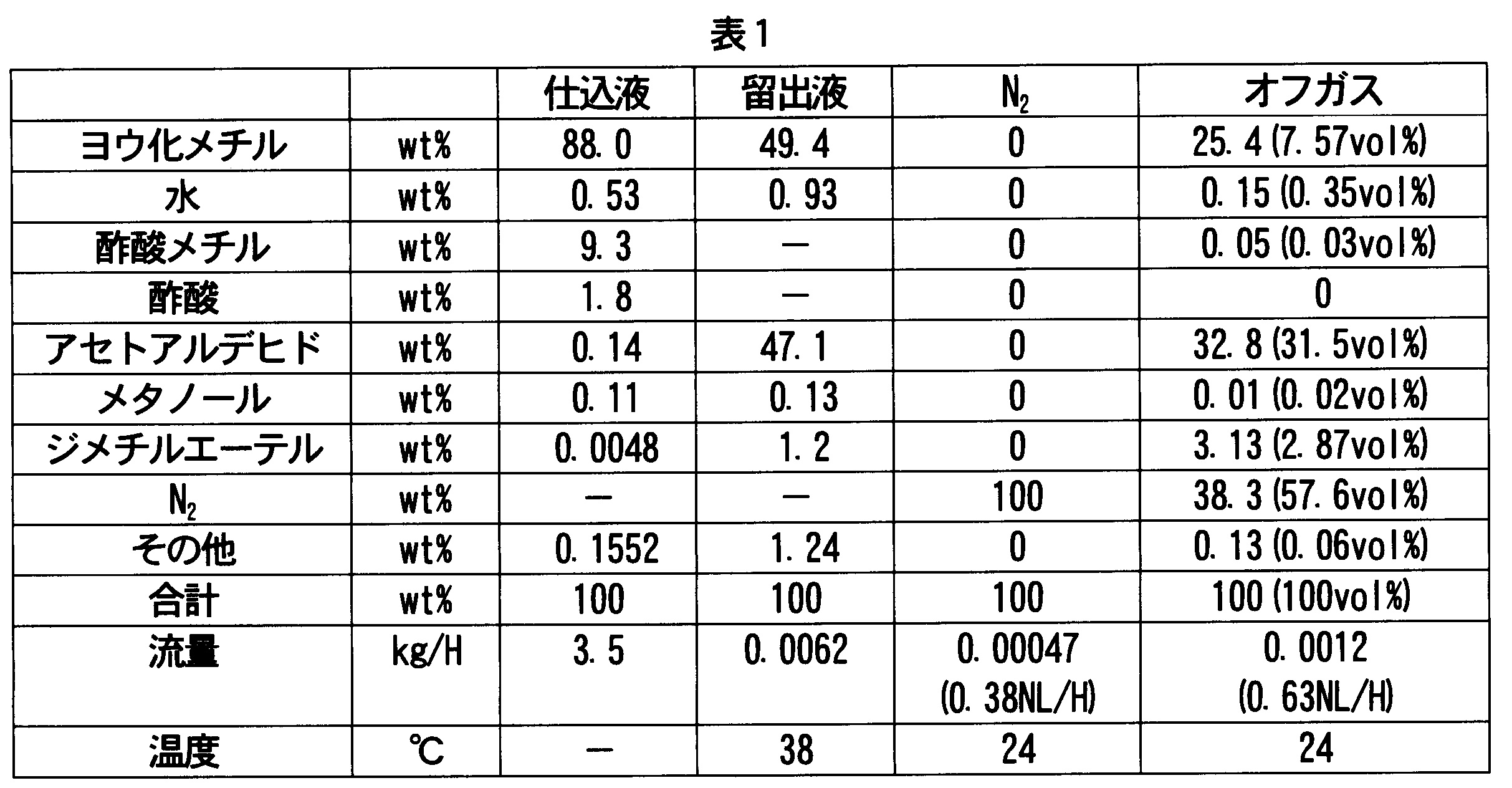
図1に示すフローにおいて、第3の蒸留塔(6b)に圧力制御ユニット68を配置し、第3の蒸留塔(6)の塔頂圧力(ゲージ圧)を0.18MPaGに制御し、比較例1と同様に、酢酸を連続的に製造したところ、安定して連続的に酢酸を製造できた。以下に、第3の蒸留塔(6b)への仕込液45、留出液(オーバーヘッド(6A)の凝縮液)67、窒素ガス(N2)72、及びオフガス71の組成を示す。
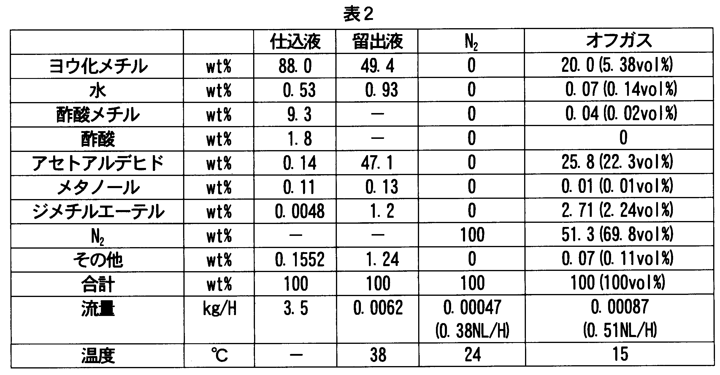
2…フラッシュ蒸発槽
3…第1の蒸留塔(スプリッターカラム)
5…デカンタ
6(6a,6b)…第2及び第3の蒸留塔
8,9…抽出器
Claims (17)
- 金属触媒、イオン性ヨウ化金属、及びヨウ化メチルを含む触媒系、並びに酢酸、酢酸メチル、水の存在下、メタノールと一酸化炭素とを反応させるためのカルボニル化反応工程と;反応混合物を揮発相と低揮発相とに分離するためのフラッシュ工程と;前記揮発相を蒸留して、ヨウ化メチル及びアセトアルデヒドから選択された少なくとも一種の低沸成分に富む第1のオーバーヘッドと、酢酸に富む粗酢酸流とに分離するための第1の蒸留工程と;前記第1のオーバーヘッドから少なくともアセトアルデヒドを分離するための分離工程とを含む酢酸の製造方法であって、前記分離工程が、
蒸留塔内の圧力を制御しつつ、第1のオーバーヘッドを蒸留し、アセトアルデヒド及びヨウ化メチルに富む第2のオーバーヘッドと、底部又は下部流とに分離するための第2の蒸留工程と、
第2のオーバーヘッドからアセトアルデヒドを抽出し、アセトアルデヒドに富む抽出液と、ヨウ化メチルに富むラフィネートとに分離する抽出工程とを含む、酢酸の製造方法。 - 分離工程が、さらに、第1のオーバーヘッドを凝縮して凝縮液を二相に分液する工程を含み、分液した上相及び/又は下相の少なくとも一部を、蒸留塔内の圧力を制御して第2の蒸留工程で蒸留する請求項1記載の方法。
- 少なくとも下相の少なくとも一部を、第2の蒸留工程で蒸留塔内の圧力を制御しながら蒸留する請求項2記載の方法。
- 第2の蒸留工程で蒸留塔内の圧力を0.1~0.7MPaに制御しつつ、第1のオーバーヘッドを蒸留する請求項1~3のいずれかに記載の方法。
- 第2の蒸留工程が複数の蒸留工程を含み、少なくとも下流側の蒸留工程で蒸留塔の圧力を制御しつつ第1のオーバーヘッドを蒸留する請求項1~4のいずれかに記載の方法。
- 第2のオーバーヘッドを凝縮して、凝縮液とオフガスとに分離する工程を含み、凝縮液を抽出工程に供し、オフガスの有用成分を直接的又は間接的に反応工程及び/又は蒸留工程にリサイクルする工程を含む請求項1~5のいずれかに記載の方法。
- オフガスをさらに凝縮し、凝縮液を反応工程及び/又は蒸留工程にリサイクルする工程を含む請求項6記載の方法。
- オフガスを加圧下で吸収溶媒に吸収させ、ヨウ化メチル、酢酸メチル、ジメチルエーテル、水及び一酸化炭素から選択された少なくとも一種の成分を吸収溶媒から放散して反応工程及び/又は蒸留工程にリサイクルする請求項6記載の方法。
- ラフィネートの少なくとも一部を少なくとも反応工程及び/又は蒸留工程にリサイクルする請求項1~8のいずれかに記載の方法。
- 第2のオーバーヘッドを間欠的(段階的)又は連続的に複数の理論段で水抽出する請求項1~9のいずれかに記載の方法。
- さらに、抽出液を蒸留して、アルデヒドを含む第4のオーバーヘッドと、底部又は下部水性流とに分離するための第4の蒸留工程を含み、水性流を抽出工程での抽出に利用する請求項1~10のいずれかに記載の方法。
- 反応工程における反応器内の反応媒体中のアセトアルデヒド濃度を400重量ppm以下に維持し、
さらに、粗酢酸流を蒸留して、精製酢酸と、低沸点成分及び高沸点成分から選択される少なくとも一方の成分とに分離する工程を含み、下記(i)~(iii)の少なくとも1つを満たす請求項1~11のいずれかに記載の方法。
(i)精製酢酸中の過マンガン酸カリウム試験値を120分以上に維持すること、
(ii)精製酢酸中のプロピオン酸濃度を200重量ppm以下に維持すること、
(iii)精製酢酸中のヨウ化物濃度を100ppb以下に維持すること - 水、酢酸、ヨウ化メチル、酢酸メチル、ジメチルエーテル、メタノール、少なくとも一つのヨウ化C2-12アルキル及び少なくとも一つの過マンガン酸還元性化合物(PRC)を含有する混合物から少なくとも一つの過マンガン酸還元性化合物(PRC)を分離する方法であって、
前記混合物を、蒸留塔内の圧力を制御しつつ蒸留して、PRCとしてのアセトアルデヒド及びヨウ化メチルに富む第2のオーバーヘッドを生成させ;
この第2のオーバーヘッドを水で抽出して、抽出液とラフィネートとに分離する、方法。 - 第2のオーバーヘッドを凝縮して、凝縮液とオフガスとに分離し、凝縮液を抽出工程に供し、オフガスから分離し、かつヨウ化メチル、酢酸メチル、ジメチルエーテル、水及び一酸化炭素から選択された少なくとも一種の成分を直接的又は間接的に反応工程及び/又は蒸留工程にリサイクルする請求項13記載の方法。
- ラフィネートの少なくとも一部を反応工程及び/又は蒸留工程にリサイクルする請求項13又は14記載の方法。
- メタノールのカルボニル化反応混合物をフラッシュ蒸発して揮発相を生成させ、この揮発相を蒸留して第1のオーバーヘッドを生成させ、この第1のオーバーヘッドを凝縮して分液させ、混合物としての上相及び/又は下相を生成させる請求項13~15のいずれかに記載の方法。
- 金属触媒、イオン性ヨウ化金属、及びヨウ化メチルを含む触媒系、並びに酢酸、酢酸メチル、水の存在下、メタノールと一酸化炭素とを反応させるためのカルボニル化反応器と;反応混合物を揮発相と低揮発相とに分離するためのフラッシャと;前記揮発相を蒸留して、ヨウ化メチル及びアセトアルデヒドから選択された少なくとも一種の低沸成分に富む第1のオーバーヘッドと、酢酸に富む粗酢酸流とに分離するための第1の蒸留塔と;前記第1のオーバーヘッドから少なくともアセトアルデヒドを分離するための分離ユニットとを含む酢酸の製造装置であって、前記分離ユニットが、
圧力制御ユニットを備え、塔内の圧力を制御しつつ、第1のオーバーヘッドを蒸留し、アセトアルデヒド及びヨウ化メチルに富む第2のオーバーヘッドと、底部又は下部流とに分離するための第2の蒸留塔と、
第2のオーバーヘッドからアセトアルデヒドを抽出し、アセトアルデヒドに富む抽出液と、ヨウ化メチルに富むラフィネートとに分離する抽出ユニットとを含む、酢酸の製造装置。
Priority Applications (6)
| Application Number | Priority Date | Filing Date | Title |
|---|---|---|---|
| KR1020187011345A KR102601400B1 (ko) | 2015-09-30 | 2016-09-21 | 아세트산의 제조 방법 및 제조 장치 |
| CN201680057961.3A CN108137462A (zh) | 2015-09-30 | 2016-09-21 | 乙酸的制造方法及制造装置 |
| SG11201800858SA SG11201800858SA (en) | 2015-09-30 | 2016-09-21 | Method and apparatus for producing acetic acid |
| JP2017543190A JP6822969B2 (ja) | 2015-09-30 | 2016-09-21 | 酢酸の製造方法及び製造装置 |
| US15/751,959 US10428006B2 (en) | 2015-09-30 | 2016-09-21 | Method and apparatus for producing acetic acid |
| US16/542,858 US10894759B2 (en) | 2015-09-30 | 2019-08-16 | Method and apparatus for producing acetic acid |
Applications Claiming Priority (2)
| Application Number | Priority Date | Filing Date | Title |
|---|---|---|---|
| JP2015194762 | 2015-09-30 | ||
| JP2015-194762 | 2015-09-30 |
Related Child Applications (2)
| Application Number | Title | Priority Date | Filing Date |
|---|---|---|---|
| US15/751,959 A-371-Of-International US10428006B2 (en) | 2015-09-30 | 2016-09-21 | Method and apparatus for producing acetic acid |
| US16/542,858 Division US10894759B2 (en) | 2015-09-30 | 2019-08-16 | Method and apparatus for producing acetic acid |
Publications (1)
| Publication Number | Publication Date |
|---|---|
| WO2017057142A1 true WO2017057142A1 (ja) | 2017-04-06 |
Family
ID=58424077
Family Applications (1)
| Application Number | Title | Priority Date | Filing Date |
|---|---|---|---|
| PCT/JP2016/077874 Ceased WO2017057142A1 (ja) | 2015-09-30 | 2016-09-21 | 酢酸の製造方法及び製造装置 |
Country Status (8)
| Country | Link |
|---|---|
| US (2) | US10428006B2 (ja) |
| JP (1) | JP6822969B2 (ja) |
| KR (1) | KR102601400B1 (ja) |
| CN (1) | CN108137462A (ja) |
| AR (1) | AR106225A1 (ja) |
| SG (1) | SG11201800858SA (ja) |
| TW (1) | TW201726594A (ja) |
| WO (1) | WO2017057142A1 (ja) |
Cited By (7)
| Publication number | Priority date | Publication date | Assignee | Title |
|---|---|---|---|---|
| WO2018135015A1 (ja) * | 2017-01-18 | 2018-07-26 | 株式会社ダイセル | 酢酸の製造方法 |
| JP6546709B1 (ja) * | 2018-07-02 | 2019-07-17 | 株式会社ダイセル | 酢酸の製造方法 |
| WO2020008505A1 (ja) * | 2018-07-02 | 2020-01-09 | 株式会社ダイセル | 酢酸の製造方法 |
| JP2022036063A (ja) * | 2020-08-19 | 2022-03-04 | 株式会社ダイセル | 酢酸の製造方法 |
| JP2022034958A (ja) * | 2020-08-19 | 2022-03-04 | 株式会社ダイセル | 酢酸の製造方法 |
| JP2022034959A (ja) * | 2020-08-19 | 2022-03-04 | 株式会社ダイセル | 酢酸の製造方法 |
| CN118565957A (zh) * | 2024-07-26 | 2024-08-30 | 福建紫金矿冶测试技术有限公司 | 一种测定硫氢化钠中氨氮含量的前处理装置、使用方法 |
Families Citing this family (5)
| Publication number | Priority date | Publication date | Assignee | Title |
|---|---|---|---|---|
| US10807935B2 (en) | 2018-11-02 | 2020-10-20 | Celanese International Corporation | Process for continuous acetic acid production |
| CN109232223A (zh) * | 2018-11-02 | 2019-01-18 | 江苏索普(集团)有限公司 | 一种合成醋酸的工艺 |
| US12404482B2 (en) * | 2019-12-19 | 2025-09-02 | Abv Technology, Inc. | Process for separating a fermented malt beverage |
| GB202015833D0 (en) * | 2020-10-06 | 2020-11-18 | Bp Chem Int Ltd | Separation process and apparatus |
| CN115253378B (zh) * | 2022-07-27 | 2024-08-09 | 郑州天一萃取科技有限公司 | 多级离心萃取系统、用于多级萃取的离心萃取机 |
Citations (4)
| Publication number | Priority date | Publication date | Assignee | Title |
|---|---|---|---|---|
| JPH0867650A (ja) * | 1994-06-15 | 1996-03-12 | Daicel Chem Ind Ltd | 高純度酢酸の製造方法 |
| JP2007526305A (ja) * | 2004-03-02 | 2007-09-13 | セラニーズ・インターナショナル・コーポレーション | メタノールのカルボニル化工程のストリームからの過マンガン酸還元性化合物の除去 |
| JP2007526310A (ja) * | 2004-03-02 | 2007-09-13 | セラニーズ・インターナショナル・コーポレーション | メタノールのカルボニル化工程のストリームからの過マンガン酸還元性化合物の除去 |
| WO2014097867A1 (ja) * | 2012-12-21 | 2014-06-26 | 株式会社ダイセル | 酢酸の製造方法 |
Family Cites Families (15)
| Publication number | Priority date | Publication date | Assignee | Title |
|---|---|---|---|---|
| US5625095A (en) | 1994-06-15 | 1997-04-29 | Daicel Chemical Industries, Ltd. | Process for producing high purity acetic acid |
| JP3673565B2 (ja) * | 1995-07-17 | 2005-07-20 | 日揮株式会社 | 蒸留装置及び蒸留方法 |
| US7855306B2 (en) * | 2005-04-28 | 2010-12-21 | Celanese International Corporation | Process for the production of acetic acid |
| JP4725360B2 (ja) * | 2006-02-27 | 2011-07-13 | 住友化学株式会社 | 蒸留システムおよび蒸留システムにおける蒸留塔の塔頂圧力を制御する方法 |
| US7619113B2 (en) | 2007-09-27 | 2009-11-17 | Celanese International Corporation | Method and apparatus for making acetic acid with improved purification |
| US7820855B2 (en) * | 2008-04-29 | 2010-10-26 | Celanese International Corporation | Method and apparatus for carbonylating methanol with acetic acid enriched flash stream |
| US7790920B2 (en) * | 2008-09-11 | 2010-09-07 | Lyondell Chemical Technology, L.P. | Preparation of acetic acid |
| CN101380522B (zh) * | 2008-10-15 | 2012-07-04 | 天津大学 | 一种加压精馏的装置和方法 |
| US7884237B2 (en) * | 2008-11-07 | 2011-02-08 | Celanese International Corp. | Methanol carbonylation with improved aldehyde removal |
| US8586789B2 (en) | 2009-03-30 | 2013-11-19 | Lyondell Chemical Technology, L.P. | Removing hydrocarbon impurities from acetic acid production intermediate |
| JP5582044B2 (ja) * | 2010-05-12 | 2014-09-03 | 三菱化学株式会社 | 蒸留塔の圧力制御方法 |
| CN103370300B (zh) * | 2010-12-15 | 2016-07-06 | 株式会社大赛璐 | 乙酸的制备方法 |
| TWI547477B (zh) | 2012-03-14 | 2016-09-01 | 大賽璐股份有限公司 | 醋酸之製造方法 |
| US8859810B2 (en) * | 2012-08-21 | 2014-10-14 | Celanese International Corporation | Process for recovering permanganate reducing compounds from an acetic acid production process |
| CN219166062U (zh) | 2020-11-27 | 2023-06-13 | 宋恩儆 | 用于哺乳靠垫的功能性外罩及功能性哺乳靠垫 |
-
2016
- 2016-09-21 WO PCT/JP2016/077874 patent/WO2017057142A1/ja not_active Ceased
- 2016-09-21 SG SG11201800858SA patent/SG11201800858SA/en unknown
- 2016-09-21 US US15/751,959 patent/US10428006B2/en active Active
- 2016-09-21 CN CN201680057961.3A patent/CN108137462A/zh active Pending
- 2016-09-21 KR KR1020187011345A patent/KR102601400B1/ko active Active
- 2016-09-21 JP JP2017543190A patent/JP6822969B2/ja active Active
- 2016-09-26 TW TW105130958A patent/TW201726594A/zh unknown
- 2016-09-30 AR ARP160103004A patent/AR106225A1/es unknown
-
2019
- 2019-08-16 US US16/542,858 patent/US10894759B2/en active Active
Patent Citations (4)
| Publication number | Priority date | Publication date | Assignee | Title |
|---|---|---|---|---|
| JPH0867650A (ja) * | 1994-06-15 | 1996-03-12 | Daicel Chem Ind Ltd | 高純度酢酸の製造方法 |
| JP2007526305A (ja) * | 2004-03-02 | 2007-09-13 | セラニーズ・インターナショナル・コーポレーション | メタノールのカルボニル化工程のストリームからの過マンガン酸還元性化合物の除去 |
| JP2007526310A (ja) * | 2004-03-02 | 2007-09-13 | セラニーズ・インターナショナル・コーポレーション | メタノールのカルボニル化工程のストリームからの過マンガン酸還元性化合物の除去 |
| WO2014097867A1 (ja) * | 2012-12-21 | 2014-06-26 | 株式会社ダイセル | 酢酸の製造方法 |
Cited By (18)
| Publication number | Priority date | Publication date | Assignee | Title |
|---|---|---|---|---|
| US10428004B2 (en) | 2017-01-18 | 2019-10-01 | Daicel Corporation | Method for producing acetic acid |
| JPWO2018135015A1 (ja) * | 2017-01-18 | 2019-01-24 | 株式会社ダイセル | 酢酸の製造方法 |
| WO2018135015A1 (ja) * | 2017-01-18 | 2018-07-26 | 株式会社ダイセル | 酢酸の製造方法 |
| GB2590221B (en) * | 2018-07-02 | 2023-04-12 | Daicel Corp | Method for producing acetic acid |
| US12060322B2 (en) | 2018-07-02 | 2024-08-13 | Daicel Corporation | Method for producing acetic acid |
| WO2020008505A1 (ja) * | 2018-07-02 | 2020-01-09 | 株式会社ダイセル | 酢酸の製造方法 |
| GB2590221A (en) * | 2018-07-02 | 2021-06-23 | Daicel Corp | Method for producing acetic acid |
| JPWO2020008505A1 (ja) * | 2018-07-02 | 2021-07-08 | 株式会社ダイセル | 酢酸の製造方法 |
| WO2020008503A1 (ja) * | 2018-07-02 | 2020-01-09 | 株式会社ダイセル | 酢酸の製造方法 |
| JP6546709B1 (ja) * | 2018-07-02 | 2019-07-17 | 株式会社ダイセル | 酢酸の製造方法 |
| JP7169353B2 (ja) | 2018-07-02 | 2022-11-10 | 株式会社ダイセル | 酢酸の製造方法 |
| JP2022034959A (ja) * | 2020-08-19 | 2022-03-04 | 株式会社ダイセル | 酢酸の製造方法 |
| JP2022034958A (ja) * | 2020-08-19 | 2022-03-04 | 株式会社ダイセル | 酢酸の製造方法 |
| JP2022036063A (ja) * | 2020-08-19 | 2022-03-04 | 株式会社ダイセル | 酢酸の製造方法 |
| JP7636747B2 (ja) | 2020-08-19 | 2025-02-27 | 株式会社ダイセル | 酢酸の製造方法 |
| JP7651274B2 (ja) | 2020-08-19 | 2025-03-26 | 株式会社ダイセル | 酢酸の製造方法 |
| JP7671653B2 (ja) | 2020-08-19 | 2025-05-02 | 株式会社ダイセル | 酢酸の製造方法 |
| CN118565957A (zh) * | 2024-07-26 | 2024-08-30 | 福建紫金矿冶测试技术有限公司 | 一种测定硫氢化钠中氨氮含量的前处理装置、使用方法 |
Also Published As
| Publication number | Publication date |
|---|---|
| SG11201800858SA (en) | 2018-04-27 |
| JP6822969B2 (ja) | 2021-01-27 |
| US20190367439A1 (en) | 2019-12-05 |
| CN108137462A (zh) | 2018-06-08 |
| KR20180059484A (ko) | 2018-06-04 |
| JPWO2017057142A1 (ja) | 2018-07-26 |
| AR106225A1 (es) | 2017-12-27 |
| TW201726594A (zh) | 2017-08-01 |
| US20180230077A1 (en) | 2018-08-16 |
| US10894759B2 (en) | 2021-01-19 |
| KR102601400B1 (ko) | 2023-11-14 |
| US10428006B2 (en) | 2019-10-01 |
Similar Documents
| Publication | Publication Date | Title |
|---|---|---|
| JP6291420B2 (ja) | 酢酸の製造方法 | |
| US10894759B2 (en) | Method and apparatus for producing acetic acid | |
| JP6404125B2 (ja) | カルボン酸の製造方法 | |
| US9149735B2 (en) | Processes for producing acetic acid | |
| KR101805240B1 (ko) | 아세트산의 제조 방법 | |
| JP5584225B2 (ja) | 改良されたアルデヒド除去率を有するメタノールカルボニル化 | |
| JP6333256B2 (ja) | 酢酸製造プロセスから過マンガン酸塩還元性化合物を回収する方法 | |
| JP6359769B2 (ja) | 酢酸の製造方法 | |
| KR102673536B1 (ko) | 아세트산을 제조하는 방법 | |
| JP2017165693A (ja) | 酢酸の製造方法 | |
| JPWO2019229856A1 (ja) | 酢酸の製造方法 |
Legal Events
| Date | Code | Title | Description |
|---|---|---|---|
| 121 | Ep: the epo has been informed by wipo that ep was designated in this application |
Ref document number: 16851316 Country of ref document: EP Kind code of ref document: A1 |
|
| ENP | Entry into the national phase |
Ref document number: 2017543190 Country of ref document: JP Kind code of ref document: A |
|
| WWE | Wipo information: entry into national phase |
Ref document number: 15751959 Country of ref document: US |
|
| WWE | Wipo information: entry into national phase |
Ref document number: 11201800858S Country of ref document: SG |
|
| NENP | Non-entry into the national phase |
Ref country code: DE |
|
| ENP | Entry into the national phase |
Ref document number: 20187011345 Country of ref document: KR Kind code of ref document: A |
|
| 122 | Ep: pct application non-entry in european phase |
Ref document number: 16851316 Country of ref document: EP Kind code of ref document: A1 |