WO2017056992A1 - 周辺監視装置 - Google Patents
周辺監視装置 Download PDFInfo
- Publication number
- WO2017056992A1 WO2017056992A1 PCT/JP2016/077105 JP2016077105W WO2017056992A1 WO 2017056992 A1 WO2017056992 A1 WO 2017056992A1 JP 2016077105 W JP2016077105 W JP 2016077105W WO 2017056992 A1 WO2017056992 A1 WO 2017056992A1
- Authority
- WO
- WIPO (PCT)
- Prior art keywords
- display
- visual field
- field range
- displayed
- vehicle
- Prior art date
- Legal status (The legal status is an assumption and is not a legal conclusion. Google has not performed a legal analysis and makes no representation as to the accuracy of the status listed.)
- Ceased
Links
Images





Classifications
-
- G—PHYSICS
- G06—COMPUTING OR CALCULATING; COUNTING
- G06T—IMAGE DATA PROCESSING OR GENERATION, IN GENERAL
- G06T1/00—General purpose image data processing
-
- H—ELECTRICITY
- H04—ELECTRIC COMMUNICATION TECHNIQUE
- H04N—PICTORIAL COMMUNICATION, e.g. TELEVISION
- H04N7/00—Television systems
- H04N7/18—Closed-circuit television [CCTV] systems, i.e. systems in which the video signal is not broadcast
Definitions
- Embodiments of the present invention relate to a periphery monitoring device.
- a technique has been proposed in which image processing is performed on a plurality of image data obtained by imaging with a camera provided so that a plurality of areas around the vehicle can be imaged, and then the image data is displayed to the user. Yes.
- the user can grasp the situation around the vehicle.
- the periphery monitoring device of the embodiment displays, for example, a reception unit that receives a first operation and a first visual field range that indicates a range around the vehicle on the display device when the first operation is received,
- the range displayed on the display device is displayed from the first visual field range to the second visual field range so as to transition from the first visual field range to the direction different from the first direction.
- a display control unit that performs control to display up to the first visual field range so as to transition. Therefore, according to this embodiment, since the situation around the vehicle is displayed, the driver can easily understand the situation around the vehicle.
- the display control unit further displays from the first visual field range to the third visual field range so as to make a transition in a direction different from the first direction. Control is performed to display up to the first visual field range so as to transition from the third visual field range to the first direction. Therefore, according to this embodiment, since the situation around the vehicle is displayed, the driver can easily understand the situation around the vehicle.
- the display control unit displays a bird's-eye view image overlooking the vehicle periphery on the display device, and the reception unit detects contact with the display area of the display device on which the bird's-eye view image is displayed. Is accepted as the first operation. Therefore, according to the present embodiment, the situation around the vehicle can be grasped by an easy operation.
- the display control unit displays the first visual field range based on the position of the overhead image corresponding to the contact position detected by the reception unit on the display device. Therefore, according to the present embodiment, since the display is performed based on the positional relationship of the overhead image, the driver can easily understand the situation around the vehicle.
- the display control unit performs a transition in the direction opposite to the first direction from the second visual field range to the first visual field range, from the first visual field range to the second visual field.
- Display control that is performed earlier than the transition in the first direction up to the range, or the transition in the first direction from the third field of view to the first field of view from the first field of view to the third Display control is performed so as to make the transition faster in the direction opposite to the first direction up to the visual field range. Therefore, according to the present embodiment, it is possible to quickly grasp the surrounding situation.
- the display control unit further superimposes display information for recognizing the position of the vehicle on the visual field range displayed on the display device. Therefore, according to the present embodiment, the positional relationship between the vehicle and the surroundings can be easily grasped by displaying the display information in a superimposed manner.
- the display control unit further displays so that a part of the vehicle such as a bumper is reflected. Therefore, according to the present embodiment, it is possible to easily grasp the gap between the vehicle and the obstacle.
- FIG. 1 is a perspective view showing an example of a state in which a part of a passenger compartment of a vehicle according to the embodiment is seen through.
- FIG. 2 is a plan view (bird's eye view) illustrating an example of the vehicle according to the embodiment.
- FIG. 3 is a block diagram illustrating an example of a functional configuration of the vehicle according to the embodiment.
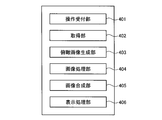
- FIG. 4 is a block diagram illustrating a configuration of a periphery monitoring unit realized in the ECU of the vehicle according to the embodiment.
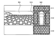
- FIG. 5 is a diagram illustrating an example of a screen displayed on the display device by the display processing unit according to the embodiment.
- FIG. 6 is a diagram illustrating a visual field range displayed by the display processing unit according to the embodiment and the overhead view viewpoint.
- FIG. 1 is a perspective view showing an example of a state in which a part of a passenger compartment of a vehicle according to the embodiment is seen through.
- FIG. 2 is a plan view (bird's eye view) illustrating an example
- FIG. 7 is a diagram illustrating screen transitions displayed by the display processing unit according to the embodiment.
- FIG. 8 is a diagram illustrating a screen transition performed following the screen transition shown in FIG.
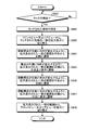
- FIG. 9 is a flowchart illustrating an overall processing procedure in the periphery monitoring unit according to the embodiment.
- FIG. 10 is a diagram illustrating a transition of an overhead viewpoint for the display processing unit of the second modification to display a partial range.
- FIG. 1 is a perspective view illustrating an example of a state in which a part of a compartment of a vehicle according to the first embodiment is seen through.
- FIG. 2 is a plan view illustrating an example of the vehicle according to the first embodiment.
- the vehicle 1 has a passenger compartment 2a in which a user (not shown) gets.
- a steering section 4 an acceleration operation section 5, a braking operation section 6, a speed change operation section 7 and the like are provided in a state that a driver as a user can operate from the seat 2b.
- Steering unit 4 is a steering wheel protruding from the dashboard (instrument panel).
- the acceleration operation unit 5 is an accelerator pedal provided under the driver's feet.
- the braking operation unit 6 is a brake pedal provided under the driver's feet.
- the speed change operation unit 7 is a shift lever protruding from the center console.
- a monitor device 11 having a display device 8 (an example of a display unit) and a sound output device 9 configured by a speaker or the like and capable of outputting various sound information is provided.
- the monitor device 11 is provided at the center of the dashboard in the passenger compartment 2a in the vehicle width direction (left-right direction).
- the display device 8 is composed of an LCD (Liquid Crystal Display), an OELD (Organic Electroluminescent Display), etc., and various information such as an image obtained by imaging the surroundings of the vehicle 1 and an image of the vehicle 1 viewed from above. It is a display part which can display.
- the display device 8 includes a transparent operation input unit 10 (so-called touch panel) that is provided on the display screen and detects a touch operation on the display screen.
- a transparent operation input unit 10 so-called touch panel
- the user can visually recognize an image displayed on the display screen of the display device 8. Further, the user can input various operations by touching the display position of the image displayed on the display screen of the display device 8 with a finger or the like.
- the monitor device 11 may have various operation units such as a switch, a dial, a joystick, and a push button.
- another audio output device may be provided at a position different from the position where the monitor device 11 is provided.
- various types of sound information can be output from both the sound output device 9 and other sound output devices.
- the monitor device 11 can also display information related to various systems such as a navigation system and an audio system.
- the vehicle 1 is a four-wheeled vehicle (four-wheeled vehicle), and has two right and left front wheels 3F and two right and left rear wheels 3R.
- the direction of the front wheel 3F changes (steers) according to the steering of the steering unit 4 (steering wheel).
- the steering system 12 (see FIG. 3) is an electric power steering system, an SBW (Steer By Wire) system, or the like, and a torque (assist torque) is added to the steering unit 4 by an actuator 12a (see FIG. 3) to generate a steering force.
- the front wheel 3F is steered.
- the vehicle 1 (vehicle body 2) includes a plurality of regions around the vehicle 1 (in this embodiment, the front of the vehicle 1, the rear of the vehicle 1, and the left side in the vehicle width direction of the vehicle 1.
- a plurality of (four in the present embodiment) imaging units 16a, 16b, 16c, 16d (hereinafter referred to as imaging units 16a, 16b) provided so as to be capable of imaging the vehicle 1 on the right side in the vehicle width direction and under the floor of the vehicle 1.
- the imaging unit 16 is a so-called digital camera having an imaging element such as a CCD (Charge Coupled Device) or a CIS (CMOS Image Sensor).
- the imaging unit 16 images a region around the vehicle 1 at a predetermined frame rate, and outputs image data of an image (a frame image constituting a moving image) obtained by the imaging.
- the imaging unit 16 includes a wide-angle lens and can capture a range of a viewing angle of 180 to 220 ° in the horizontal direction.
- the imaging units 16 a, 16 b, 16 c, and 16 d are provided with their optical axes directed downward of the vehicle 1. Therefore, the imaging units 16a, 16b, 16c, and 16d can image a road surface on which the vehicle 1 can move and a region above the road surface (external environment).
- the imaging unit 16 a is provided at the front end 2 c (for example, a front grill) of the vehicle body 2 and can capture an area in front of the vehicle 1.
- the imaging unit 16b is provided at the rear end 2e of the vehicle body 2 (for example, the rear trunk door 2h), and can capture an area behind the vehicle 1.
- the imaging unit 16c is provided at the left end 2d of the vehicle body 2 in the vehicle width direction (for example, the left door mirror 2g), and can image the left region of the vehicle 1.
- the imaging unit 16d is provided at the right end 2f of the vehicle body 2 in the vehicle width direction (for example, the right door mirror 2g), and can image the right region of the vehicle 1.
- FIG. 3 is a block diagram illustrating an example of a functional configuration of the vehicle according to the first embodiment.
- the vehicle 1 includes a monitor device 11, a steering system 12, an actuator 12a, a torque sensor 12b, an ECU (Electronic Control Unit) 14, an obstacle sensor 17, a brake system 18, A brake sensor 18b, a steering angle sensor 19, an accelerator sensor 20, a shift sensor 21, and a wheel speed sensor 22 are provided.
- the monitor device 11, the steering system 12, the ECU 14, the obstacle sensor 17, the brake system 18, the rudder angle sensor 19, the accelerator sensor 20, the shift sensor 21, and the wheel speed sensor 22 are in electrical communication. It is electrically connected via a line (hereinafter referred to as in-vehicle network 23).
- the in-vehicle network 23 is configured by, for example, a CAN (Controller Area Network).
- the ECU14 performs an image process with respect to the image data obtained by the imaging of the imaging part 16, and displays the image data which performed the said image process on the display apparatus 8.
- the ECU 14 controls each part such as the steering system 12 and the brake system 18 by transmitting a control signal to each part of the vehicle 1 via the in-vehicle network 23.
- the ECU 14 acquires detection results of the torque sensor 12b, the obstacle sensor 17, the brake sensor 18b, the steering angle sensor 19, the accelerator sensor 20, the shift sensor 21, the wheel speed sensor 22, and the like via the in-vehicle network 23.
- the ECU 14 acquires operation information input by the user using the operation input unit 10.
- the ECU 14 includes a CPU (Central Processing Unit) 14a, a ROM (Read Only Memory) 14b, a RAM (Random Access Memory) 14c, a display control unit 14d, a voice control unit 14e, an SSD (Solid State Drive) 14f, and the like.
- CPU14a is a control part which controls the vehicle 1 whole, Comprising: Various processes, such as the acquisition process of the movement path
- the CPU 14a reads a program stored in a nonvolatile storage device such as the ROM 14b or the SSD 14f, and executes various processes according to the program.
- the RAM 14c is used as a work area when the CPU 14a executes various processes according to a program, and temporarily stores data used for various processes executed by the CPU 14a.
- the display control unit 14d performs image processing on image data (for example, image data obtained by imaging by the imaging unit 16) displayed on the display device 8, display processing of image data on the display device 8, and the like.
- the voice control unit 14e executes processing for outputting sound data such as voice from the voice output device 9.
- the SSD 14f is a nonvolatile storage unit that can rewrite various data, and retains the various data even when the ECU 14 is turned off.
- the ECU 14 may include a processor such as a DSP (Digital Signal Processor) and a logic circuit instead of the CPU 14a as a control unit that controls the entire vehicle 1.
- the SSD 14f is used as a main storage device that stores a program executed by the CPU 14a.
- an HDD Hard Disk Drive
- the ECU 14 includes the SSD 14f or HDD as the main storage device.
- the present invention is not limited to this, and the external device of the ECU 14 may include the SSD 14f or HDD.
- Each configuration in the periphery monitoring unit 400 illustrated in FIG. 4 is realized by the CPU 14a configured as the ECU 14 in FIG. 3 executing a program stored in the ROM 14b. That is, the periphery monitoring unit 400 executes a program stored in the ROM 14b, so that an operation reception unit 401, an acquisition unit 402, an overhead image generation unit 403, an image processing unit 404, an image composition unit 405, The display processing unit 406 is realized. In addition, you may comprise so that these each part may be implement
- the operation reception unit 401 receives instruction signals (control signals) from the operation input unit 10 and an operation unit (not shown).
- the operation receiving unit 401 can receive an operation from the driver from these instruction signals.
- the operation unit is, for example, a push button or a switch.
- the operation reception unit 401 receives from the operation input unit 10 an instruction signal indicating a so-called touch operation in which contact with a display area displayed on the display device 8 is detected.
- the acquisition unit 402 acquires the image data captured by the imaging unit 16.
- the acquisition unit 402 acquires image data every time the imaging unit 16 captures an image. In other words, the acquisition unit 402 can acquire captured image data in real time.
- the overhead image generation unit 403 generates, based on the image data acquired by the acquisition unit 402, overhead image data that is the ground around the vehicle 1 and the bird's-eye view of the ground around the vehicle 1 from above. Note that any method may be used to generate the overhead image data from the image data, and for example, the image data may be converted using a mapping table.
- the image processing unit 404 performs image processing on the image data acquired by the acquisition unit 402 as necessary. Specific image processing will be described later.
- the image synthesis unit 405 synthesizes the image data that has been subjected to image processing by the image processing unit 404 and the overhead image data generated by the overhead image generation unit 403, and generates image data to be displayed on the display device 8. .
- the display processing unit 406 controls display of data on the display device 8. For example, the display processing unit 406 performs control to display the image data generated by the image composition unit 405 on the display device 8.
- FIG. 5 is a diagram showing an example of a screen displayed on the display device 8 by the display processing unit 406.
- the image data captured by the imaging unit 16 a is arranged in the display area 501 in the monitor, and the overhead image data generated by the overhead image generation unit 403 is arranged in the overhead image area 502.
- An example screen is shown.
- image data captured by the imaging unit 16a that is, a so-called front view is displayed will be described.
- image data captured by the imaging unit 16b, a so-called rear view, and the like may be displayed.
- the image data displayed in the display area 501 in the monitor is switched.
- the displayed image data varies depending on which of the front area 511, the right area 512, the left area 513, and the rear area 514 the touched position is included.
- the image processing unit 404 performs image conversion that makes it appear that the image data captured by the imaging unit 16a is captured from an overhead viewpoint. Perform the enlargement process. Then, the image composition unit 405 generates image data in which a part of the enlarged range (hereinafter also referred to as a visual field range) and the overhead image data are arranged. Then, the display processing unit 406 displays the generated image data.
- the display processing unit 406 displays a partial range on the display device 8 based on the position of the overhead image data corresponding to the contact position detected by the operation receiving unit 401 as the touch operation.
- the display processing unit 406 performs display control for the part of the enlarged range so that the overhead viewpoint changes in the left and right directions.
- a part of the displayed range that changes according to the change of the overhead view viewpoint is referred to as a visual field range.
- FIG. 6 is a diagram showing the visual field range displayed by the display processing unit 406 and the overhead view viewpoint.
- the display processing unit 406 enlarges and displays the first visual field range 601 representing a part of the image data captured by the imaging unit 16 a in the display area 501 in the monitor on the display device 8.
- the image processing unit 404 performs viewpoint conversion on the image data in the first visual field range 601 so that the image data is captured from the overhead viewpoint 611.
- the display processing unit 406 changes the visual field range displayed in the display area 501 in the monitor.
- the display processing unit 406 is a part of the image data captured by the imaging unit 16a from the first visual field range 601 so that the direction of the overhead viewpoint 611 is changed.
- An animation display for transitioning to the second visual field range 602 (different from the first visual field range 601) is performed.
- the display processing unit 406 performs an animation display for transition from the second visual field range 602 to the first visual field range 601 so that the direction of the overhead view viewpoint 611 changes. .
- the display processing unit 406 starts from the first visual field range 601 (the imaging unit 16 a performs imaging so that the direction of the overhead viewpoint 611 continuously changes.
- an animation display is performed in which a transition is made to a third visual field range 603 (which is a partial range of the image data, which is different from the first visual field range 601 and the second visual field range 602).
- the displayed image data is subjected to viewpoint conversion so that the image data is taken from the overhead viewpoint 611.
- the display processing unit 406 displays the first visual field range 601 around the vehicle 1. Displayed on the display device 8, an area displayed on the display device 8 is displayed in an animation display that transitions from the first visual field range 601 to the left from the vehicle 1, and is displayed up to the second visual field range 602.
- the first visual field range 601 is displayed in an animation display that transitions from the visual field range 602 in the direction opposite to the left direction (right direction), and from the first visual field range 601 in the direction opposite to the left direction (right direction).
- Up to the third visual field range 603 is displayed in the animation display that transitions, and up to the first visual field range 601 in the animation display that transitions leftward from the third visual field range 603. Perform Shimesuru control.
- the example of transitioning to the left direction and then transitioning to the direction opposite to the left direction (right direction) has been described.
- the present embodiment is not limited to the direction opposite to the left direction, and is different from the left direction. Just make a transition.
- the second visual field range 602 returns to the first visual field range 601 and then transitions in the third visual field range 603.
- the first visual field range 601 is returned. You may end at the point.
- animation display may be performed only in the specified direction.
- the display processing unit 406 displays the first visual field range 601 as taken from the overhead viewpoint 611
- the display processing unit 406 displays the animation display that transitions to the left and the right (the direction opposite to the left).
- the image processing unit 404 performs viewpoint conversion to make the direction of the overhead view viewpoint 611 appear to change with respect to the image data in the visual field range to be displayed.
- the imaging unit 16 captures a range of a viewing angle of 180 to 220 ° in the horizontal direction.
- a viewing angle 180 to 220 ° in the horizontal direction.
- the imaging unit 16 has taken a wider range.
- the bird's-eye view image data can grasp the entire surroundings of the vehicle, but it is difficult to grasp the detailed portions of the surroundings. Therefore, in the present embodiment, when the driver desires, after performing image processing so as to be seen from a bird's-eye view including an area that is not normally displayed, animation display is performed to make a transition in the left-right direction. It was. As a result, the driver can recognize the situation of a place that is difficult to grasp around the vehicle.
- FIG. 7 is a diagram illustrating screen transitions displayed by the display processing unit 406.
- the overhead image data is arranged in the overhead image area 701, and a partial range 711 of the image data captured by the imaging unit 16 is enlarged and displayed in the display area 702 in the monitor.
- Image data is arranged.
- the display area 702 in the monitor includes a part of the vehicle 1 (a bumper in the example shown in FIG. 7A) 712. As a result, the driver can recognize the enlarged area.
- the screen example shown in FIG. 7A is displayed for 0.5 seconds. Thereafter, the animation display in which the displayed range is shifted leftward is started.
- the display processing unit 406 displays image data in which the displayed range is shifted leftward from a partial range 711 in the display area 702 in the monitor.
- the display processing unit 406 superimposes and displays a mark 721 for recognizing the position of the left end of the vehicle 1 over the visual field range displayed in the display area 702 in the monitor. To do. As a result, the driver can grasp the positional relationship.
- a mark display information
- any mark that can recognize the position of the vehicle may be used.
- the mark 722 on the overhead image area 701 at the same position as the mark 721, the position of the vehicle can be more easily recognized.
- the display processing unit 406 performs an animation display in which the displayed visual field range further shifts to the left in the display area 702 in the monitor. Then, after displaying the screen example of FIG. 7 (4), the animation display in which the displayed visual field range shifts in the left direction is stopped. The animation display transitioning to the left shown in FIGS. 7 (2) to (4) is performed for 0.7 seconds.
- the display processing unit 406 causes the display field range displayed in the display area 702 in the monitor to transition to the right direction (the opposite direction to the left direction).
- Animated display As shown in the screen example of FIG. 7 (7), the display is a partial range 711 similar to that of FIG. 7 (1).
- the animation display transitioning to the right shown in FIGS. 7 (4) to (7) is performed for 0.3 seconds.
- a partial area in the front direction of the vehicle 1 is enlarged and displayed for 0.5 seconds, and then the left area in front of the vehicle 1 is animated in one second.
- the animation display returning to the right direction increases the display transition speed compared to the animation display proceeding to the left direction.
- the display processing unit 406 performs a right transition from the partial area illustrated in FIG. 7 (4) to the central partial range 711 from the central partial range 711 to FIG. Display control is performed so as to be faster than the leftward transition to the partial area shown in 4).
- the display processing unit 406 of the present embodiment makes a slow transition when a part of the range displayed as the visual field range advances in a direction that the driver does not see, and displays it as the visual field region in the direction that the driver has already viewed. Transition early if some range returns. As a result, the driver can confirm the location he / she wants to see in as short a time as possible.
- the driver when displaying a partial area in the right direction or the left direction from the center (vehicle 1), it is displayed by displaying the direction of the overhead view viewpoint as changing (partial range).
- the visual field range is displayed in an oblique direction from the overhead viewpoint.
- the driver can check an object existing ahead of the end of the vehicle 1.
- the displayed visual field range is displayed in an oblique direction, the driver can determine a three-dimensional object that has been difficult in the case of an overhead image.
- region the positional relationship between a vehicle and the displayed thing can be easily grasped
- FIG. 8 is a diagram illustrating a screen transition performed following the screen transition shown in FIG.
- the animation displayed in the right direction as shown in FIGS. 7 (5) and (6) is continuously displayed, so that the displayed area is one.
- the image data transitioned to the right from the part range 711 is displayed.
- a mark 821 indicating the position of the right end of the vehicle 1 is superimposed and displayed. As a result, the driver can grasp the positional relationship.
- the display processing unit 406 performs an animation display in which the displayed range further shifts to the right in the display area 702 in the monitor. Then, after displaying the screen example of FIG. 7 (3), the animation display in which the displayed range transitions to the right is stopped.
- the animation display transitioning in the right direction shown in FIGS. 8 (1) to (3) is performed for 0.7 seconds.
- the display processing unit 406 causes the display range to shift to the left (opposite to the right) in the display area 702 in the monitor. Perform animation display. Then, as shown in the screen example of FIG. 8 (6), a partial range 711 similar to that of FIG. 7 (1) displayed first is displayed. Thereafter, the display is switched again to the front view or the rear view. Note that the animation display transitioning to the left shown in FIGS. 8 (4) to (6) is performed for 0.3 seconds.
- the area in the right direction in front of the vehicle 1 is displayed in animation for 1 second.
- the animation display that returns to the left direction increases the display transition speed compared to the animation display that proceeds to the right direction.
- the display processing unit 406 performs a rightward transition from the partial region illustrated in FIG. 8C to the partial central range 711 from the partial central range 711 to FIG. Display control is performed so as to be faster than the rightward transition to the partial area shown in 3).
- FIG. 9 is a flowchart illustrating a procedure of the above-described processing in the periphery monitoring unit 400 according to the present embodiment.
- the display processing unit 406 already displays the front view or rear view in combination with the overhead image data.
- the operation reception part 401 determines whether the touch with respect to the bird's-eye view image area was detected (S901). If it is determined that no touch is detected (S901: No), the display combining the front view or the rear view and the overhead image data is continuously performed until the touch is detected.
- the operation reception unit 401 identifies the touched area (S902).
- the operation reception unit 401 identifies which area is the front area, the rear area, the right area, or the left area of the vehicle represented in the overhead image data as the touched area.
- the display processing unit 406 switches the display area in the monitor from the front view or the rear view to an enlarged display of a part of the touched area (front area, rear area, right area, or left area) ( S903).
- the display processing unit 406 performs animation display in which the visual field range representing a part of the enlarged range is shifted from the center to the left side so that the direction of the overhead viewpoint changes to the left side (S904).
- the display processing unit 406 displays an animation that causes the visual field range representing a part of the enlarged range to transition from the left side to the center more quickly than S904 so that the direction of the overhead view viewpoint changes to the right side. (S905).
- the display processing unit 406 performs animation display in which a visual field range representing a part of the enlarged range is shifted from the center to the right side so that the direction of the overhead viewpoint changes to the right side (S906).
- the display processing unit 406 displays an animation that causes the visual field range representing a part of the magnified display range to transition from the right side to the center faster than S906 so that the direction of the overhead viewpoint changes to the left side. (S907).
- the display processing unit 406 switches the display of the front view or the rear view after displaying a part of the center of the enlarged display for 0.5 seconds (S908).
- the transition direction is not limited, and the transition to the right direction may be performed first. .
- this embodiment demonstrated the example which performs display control using the touch operation with respect to overhead image data as a trigger, it is good also considering operation other than the touch operation with respect to overhead image data as a trigger.
- Modification 1 In the first embodiment, according to the position of the touch operation performed on the bird's-eye view image data, it is specified which area is the front area, the rear area, the right area, or the left area of the vehicle, and the display is performed. The example to do was demonstrated. However, the present invention is not limited to a method of selecting a displayed area from a predetermined area. Therefore, in this modification, an example in which the display is centered on the position touched by the user is used.
- the operation accepting unit 401 of this modification accepts a touch operation on the overhead image data displayed on the display device. Then, the operation reception unit 401 identifies the position coordinates on the touched overhead image data.
- the display processing unit 406 enlarges and displays a part of the range of the image data captured by the imaging unit 16 around the area corresponding to the specified position coordinates. After that, the position and orientation of the overhead view viewpoint are changed around the specified position, and the same control as in the first embodiment is performed.
- a range captured by the plurality of imaging units 16 may be included.
- the image processing unit 404 may combine the image data captured by the plurality of imaging units 16, and the display processing unit 406 may display the combined image data as a partial range.
- the display processing unit 406 displays an animation display that enlarges and displays a region centered on the position where the touch operation is performed, and makes a transition from the region to the left and right. I decided to do it. Thereby, the driver can recognize the surrounding situation in more detail by performing the display around the position where the driver has shown interest.
- Modification 2 1st Embodiment and the modification 1 demonstrated the example which the display process part 406 displays so that direction of a bird's-eye view viewpoint may change.
- the present invention is not limited to the method of fixing the overhead view viewpoint as in the first embodiment and the first modification. Therefore, in Modification 2, an example will be described in which display is performed so that the overhead viewpoint moves.
- the operation receiving unit 401 receives a touch operation on the overhead image area displayed on the display device 8 as in the first modification. Then, the operation reception unit 401 specifies the position coordinates of the touched overhead image area.
- the display processing unit 406 displays a visual field range in which a part of the range is enlarged around the position corresponding to the specified position coordinate in the image data captured by the imaging unit 16. The subsequent display will be described with reference to FIG.
- FIG. 10 is a diagram showing a transition of an overhead view for the display processing unit 406 of the second modification to display a partial range.
- the display processing unit 406 displays a field-of-view range 1011 representing a part of image data captured by the imaging unit 16 as captured from the overhead viewpoint 1001.
- the image processing unit 404 performs viewpoint conversion so that the visual field range 1011 is imaged from the overhead viewpoint 1001. The same viewpoint conversion is performed in some of the visual field ranges 1012, 1013 described below.
- the display processing unit 406 performs an animation display for changing the displayed visual field range so that the overhead viewpoint 1001 moves to the overhead viewpoint 1002. Then, the display processing unit 406 displays the visual field range 1012 representing a part of the image data captured by the imaging unit 16 as captured from the overhead viewpoint 1002.
- the display processing unit 406 performs an animation display in which the displayed visual field range is changed so as to move from the overhead viewpoint 1002 to the overhead viewpoint 1003 via the overhead viewpoint 1001. Then, the display processing unit 406 displays a visual field range 1013 representing a part of the image data captured by the imaging unit 16 as captured from the overhead viewpoint 1003.
- This modification has described an example in which the position coordinates of the touched overhead image area are specified and a part of the range is enlarged and displayed around the specified position coordinates.
- the movement of the overhead viewpoint is not limited to the example centered on the specified position coordinates, and the overhead viewpoint moves when the specified area is displayed as in the first embodiment. May be animated.
- the display control unit displays the first area as photographed from the first viewpoint, displays the transition in the first direction, and displays the transition in the direction opposite to the first direction. Display control is performed so that the orientation of the viewpoint of 1 is changed.
Landscapes
- Engineering & Computer Science (AREA)
- Physics & Mathematics (AREA)
- General Physics & Mathematics (AREA)
- Theoretical Computer Science (AREA)
- Multimedia (AREA)
- Signal Processing (AREA)
- Closed-Circuit Television Systems (AREA)
- Image Processing (AREA)
- Image Analysis (AREA)
Abstract
実施形態の周辺監視装置は、第1の操作を受け付ける受付部と、第1の操作を受け付けた場合に、車両の周辺の範囲を示した第1の視野範囲を表示装置に表示し、表示装置に表示される範囲を当該第1の視野範囲から第1の方向に遷移していくように第2の視野範囲まで表示し、当該第2の視野範囲から第1の方向と異なる方向に遷移していくように当該第1の視野範囲まで表示する制御を行う表示制御部と、を備える。
Description
本発明の実施形態は、周辺監視装置に関する。
車両の周囲の複数の領域を撮像可能に設けられたカメラの撮像により得られた複数の画像データに対して画像処理を行った後に、当該画像データをユーザに対して表示する技術が提案されている。当該技術により、ユーザは、車両の周囲の状況を把握することができる。
しかしながら、車両の周囲全体を表示すると、細かいところまで把握しにくい。車両の周辺の一部領域を拡大して表示した場合、ユーザは、当該一部領域がどの位置なのか認識しにくいと共に、表示された一部領域以外の他の領域がどのような状況か把握しにくい。
実施形態の周辺監視装置は、例えば、第1の操作を受け付ける受付部と、第1の操作を受け付けた場合に、車両の周辺の範囲を示した第1の視野範囲を表示装置に表示し、表示装置に表示される範囲を当該第1の視野範囲から第1の方向に遷移していくように第2の視野範囲まで表示し、当該第2の視野範囲から第1の方向と異なる方向に遷移していくように当該第1の視野範囲まで表示する制御を行う表示制御部と、を備える。よって、本実施形態によれば、車両の周囲の状況が表示されるので、運転者が車両の周囲の状況の把握が容易になる。
また、上記周辺監視装置は、例えば、表示制御部が、さらに、第1の視野範囲から、第1の方向とは異なる方向に遷移していくように第3の視野範囲まで表示し、当該第3の視野範囲から第1の方向に遷移していくように第1の視野範囲まで表示する制御を行う。よって、本実施形態によれば、車両の周囲の状況が表示されるので、運転者が車両の周囲の状況の把握が容易になる。
また、上記周辺監視装置は、例えば、表示制御部は、車両周辺を俯瞰した俯瞰画像を表示装置に表示し、受付部は、俯瞰画像が表示された表示装置の表示領域に対する接触を検出したことを第1の操作として受け付ける。よって、本実施形態によれば、容易な操作で、車両の周囲の状況を把握できる。
また、上記周辺監視装置は、例えば、表示制御部は、受付部が検出した接触位置に対応する、俯瞰画像の位置に基づいた、第1の視野範囲を表示装置に表示する。よって、本実施形態によれば、俯瞰画像の位置関係に基づいて表示が行われるので、運転者が車両の周囲の状況の把握が容易になる。
また、上記周辺監視装置は、例えば、表示制御部は、第2の視野範囲から第1の視野範囲までの第1の方向と反対方向への遷移を、第1の視野範囲から第2の視野範囲までの第1の方向への遷移より早くする表示制御を行う、又は、第3の視野範囲から第1の視野範囲までの第1の方向への遷移を、第1の視野範囲から第3の視野範囲までの第1の方向と反対方向への遷移より早くする表示制御を行う。よって、本実施形態によれば、周囲の状況を早く把握することができる。
また、上記周辺監視装置は、例えば、表示制御部は、さらに、表示装置に表示される視野範囲に対して、車両の位置を認識するための表示情報を重畳表示する。よって、本実施形態によれば、表示情報を重畳表示することで、車両と周囲の位置関係を、容易に把握することができる。
また、上記周辺監視装置は、例えば、表示制御部は、さらに、バンパなど車両の一部が映り込むように表示する。よって、本実施形態によれば、車両と障害物との隙間を容易に把握することができる。
(第1の実施形態)
まず、図1および図2を用いて、本実施形態にかかる周辺監視装置を搭載した車両の概略構成について説明する。図1は、第1の実施形態にかかる車両の車室の一部が透視された状態の一例が示された斜視図である。図2は、第1の実施形態にかかる車両の一例を示す平面図である。
まず、図1および図2を用いて、本実施形態にかかる周辺監視装置を搭載した車両の概略構成について説明する。図1は、第1の実施形態にかかる車両の車室の一部が透視された状態の一例が示された斜視図である。図2は、第1の実施形態にかかる車両の一例を示す平面図である。
図1に示すように、本実施形態にかかる車両1は、図示しないユーザが乗車する車室2aを有している。車室2a内には、ユーザとしての運転者が座席2bから操作可能な状態で、操舵部4、加速操作部5、制動操作部6、変速操作部7等が設けられている。
操舵部4は、ダッシュボード(インストルメントパネル)から突出したステアリングホイールである。加速操作部5は、運転者の足下に設けられたアクセルペダルである。制動操作部6は、運転者の足下に設けられたブレーキペダルである。変速操作部7は、センターコンソールから突出したシフトレバーである。
また、車室2a内には、表示装置8(表示部の一例)と、スピーカ等で構成され各種の音情報を出力可能な音声出力装置9と、を有するモニタ装置11が設けられている。モニタ装置11は、車室2a内のダッシュボードの車幅方向(左右方向)の中央部に設けられている。表示装置8は、LCD(Liquid Crystal Display)やOELD(Organic Electroluminescent Display)等で構成され、車両1の周囲を撮像して得られた画像および車両1を上から見たような画像等の各種情報を表示可能な表示部である。
本実施形態では、表示装置8は、表示画面上に設けられかつ当該表示画面に対するタッチ操作を検出する透明な操作入力部10(所謂、タッチパネル)を有している。ユーザは、表示装置8の表示画面に表示される画像を視認することができる。また、ユーザは、表示装置8の表示画面に表示される画像の表示位置に指等で接触することで、各種の操作を入力できる。
また、モニタ装置11は、スイッチ、ダイヤル、ジョイスティック、押しボタン等の各種の操作部を有していても良い。また、車室2a内には、モニタ装置11が設けられた位置とは異なる位置に、他の音声出力装置が設けられていても良い。この場合、音声出力装置9および他の音声出力装置の両方から、各種の音情報を出力することができる。また、本実施形態では、モニタ装置11は、ナビゲーションシステムやオーディオシステム等の各種システムに関する情報も表示可能とする。
また、本実施形態では、車両1は、図1および図2に示すように、四輪車(四輪自動車)であり、左右2つの前輪3Fと、左右2つの後輪3Rとを有する。前輪3Fの向きが操舵部4(ステアリングホイール)の操舵に応じて変化(転舵)する。操舵システム12(図3参照)は、電動パワーステアリングシステムやSBW(Steer By Wire)システム等であり、アクチュエータ12a(図3参照)によって操舵部4にトルク(アシストトルク)を付加して操舵力を補って、前輪3Fを操舵する。
また、図2に示すように、車両1(車体2)は、当該車両1の周囲の複数の領域(本実施形態では、車両1の前方、車両1の後方、車両1の車幅方向の左側、車両1の車幅方向の右側、車両1の床下)を撮像可能に設けられた複数(本実施形態では、4つ)の撮像部16a,16b,16c,16d,(以下、撮像部16a,16b,16c,16dを区別する必要が無い場合には、撮像部16と記載する)を有している。撮像部16は、CCD(Charge Coupled Device)やCIS(CMOS Image Sensor)等の撮像素子を有する所謂デジタルカメラとする。
本実施形態では、撮像部16は、所定のフレームレートで車両1の周囲の領域を撮像し、当該撮像により得られた画像(動画像を構成するフレーム画像)の画像データを出力する。また、本実施形態では、撮像部16は、広角レンズを有し、水平方向に180~220°の視野角の範囲を撮像可能である。また、撮像部16a,16b,16c,16dは、その光軸が車両1の下方に向けられて設けられている。したがって、撮像部16a,16b,16c,16dは、車両1が移動可能な路面と当該路面から上方の領域(外部の環境)を撮像可能である。
具体的には、撮像部16aは、車体2の前側の端部2c(例えば、フロントグリル)に設けられ、車両1の前方の領域を撮像可能である。また、撮像部16bは、車体2の後側の端部2e(例えば、リアトランクのドア2h)に設けられ、車両1の後方の領域を撮像可能である。撮像部16cは、車体2の車幅方向の左側の端部2d(例えば、左側のドアミラー2g)に設けられ、車両1の左側の領域を撮像可能である。撮像部16dは、車体2の車幅方向の右側の端部2f(例えば、右側のドアミラー2g)に設けられ、車両1の右側の領域を撮像可能である。
次に、図3を用いて、本実施形態にかかる車両1の機能構成について説明する。図3は、第1の実施形態にかかる車両の機能構成の一例を示すブロック図である。
図3に示すように、本実施形態にかかる車両1は、モニタ装置11と、操舵システム12と、アクチュエータ12a、トルクセンサ12b、ECU(Electronic Control Unit)14、障害物センサ17、ブレーキシステム18、ブレーキセンサ18b、舵角センサ19、アクセルセンサ20、シフトセンサ21および車輪速センサ22を有している。そして、モニタ装置11と、操舵システム12と、ECU14と、障害物センサ17と、ブレーキシステム18と、舵角センサ19、アクセルセンサ20と、シフトセンサ21と、車輪速センサ22とは、電気通信回線(以下、車内ネットワーク23と言う)を介して電気的に接続されている。車内ネットワーク23は、例えば、CAN(Controller Area Network)によって構成される。
ECU14は、撮像部16の撮像により得られた画像データに対して画像処理を実行し、当該画像処理を実行した画像データを表示装置8に表示する。また、ECU14は、車内ネットワーク23を介して、車両1の各部へ制御信号を送信することで、操舵システム12、ブレーキシステム18等の各部を制御する。また、ECU14は、車内ネットワーク23を介して、トルクセンサ12b、障害物センサ17、ブレーキセンサ18b、舵角センサ19、アクセルセンサ20、シフトセンサ21、車輪速センサ22等の検出結果を取得する。また、ECU14は、操作入力部10を用いてユーザにより入力された操作情報を取得する。
具体的には、ECU14は、CPU(Central Processing Unit)14a、ROM(Read Only Memory)14b、RAM(Random Access Memory)14c、表示制御部14d、音声制御部14e、SSD(Solid State Drive)14f等を有している。CPU14aは、車両1全体を制御する制御部であって、車両1の移動経路の取得処理、物体との干渉の有無の判断処理等の各種処理を実行する。CPU14aは、ROM14bやSSD14f等の不揮発性の記憶装置に記憶されたプログラムを読み出し、当該プログラムに従って各種処理を実行する。RAM14cは、CPU14aがプログラムに従って各種処理を実行する際の作業領域として用いられ、CPU14aにより実行される各種処理に用いるデータを一時的に記憶する。
表示制御部14dは、表示装置8に表示する画像データ(例えば、撮像部16の撮像により得られた画像データ)に対する画像処理、表示装置8に対する画像データの表示処理等を実行する。音声制御部14eは、音声出力装置9から音声等の音データを出力する処理等を実行する。SSD14fは、各種データを書き換え可能な不揮発性の記憶部であり、ECU14の電源がオフされた場合であっても当該各種データを保持する。
本実施形態では、CPU14a、ROM14bおよびRAM14cは、1つの集積回路に搭載されているものとする。また、ECU14は、車両1全体を制御する制御部としてCPU14aに替えて、DSP(Digital Signal Processor)等のプロセッサや論理回路を有していても良い。また、本実施形態では、CPU14aにより実行されるプログラム等を記憶する主記憶装置としてSSD14fを用いているが、これに限定するものではなく、例えばHDD(Hard Disk Drive)等を主記憶装置として用いても良い。また、本実施形態では、ECU14が主記憶装置としてのSSD14fまたはHDDを有しているが、これに限定するものではなく、ECU14の外部装置がSSD14fまたはHDDを有していても良い。
次に、ECU14内に実現される周辺監視部400の構成について説明する。図4に示す周辺監視部400内の各構成は、図3のECU14として構成されたCPU14aが、ROM14b内に格納されたプログラムを実行することで実現される。すなわち、周辺監視部400は、ROM14b内に格納されたプログラムを実行することで、操作受付部401と、取得部402と、俯瞰画像生成部403と、画像処理部404と、画像合成部405と、表示処理部406と、を実現する。なお、これらの各部をハードウェアで実現するように構成してもよい。
操作受付部401は、操作入力部10や(図示しない)操作部等の指示信号(制御信号)を受け付ける。操作受付部401は、これら指示信号から、運転者からの操作を受け付けることができる。操作部は、例えば、押しボタンやスイッチ等である。例えば、操作受付部401は、表示装置8に表示された表示領域に対する接触を検知した、所謂タッチ操作を示した指示信号を、操作入力部10から受け付ける。
取得部402は、撮像部16により撮像された画像データを取得する。取得部402は、撮像部16が撮像する毎に、画像データを取得する。換言すれば、取得部402は、撮影された画像データを、リアルタイムに取得できる。
俯瞰画像生成部403は、取得部402が取得した画像データに基づいて、車両1の周辺の地面であり且つ当該車両1周辺の地面を上方から俯瞰した俯瞰画像データを生成する。なお、画像データから俯瞰画像データを生成する手法はどのような手法を用いても良く、例えばマッピングテーブルを用いて変換しても良い。
画像処理部404は、必要に応じて、取得部402が取得した画像データに対して、画像処理を行う。具体的な画像処理については、後述する。
画像合成部405は、画像処理部404により画像処理が行われた画像データや、俯瞰画像生成部403により生成された俯瞰画像データを合成し、表示装置8に表示するための画像データを生成する。
表示処理部406は、表示装置8にデータの表示制御を行う。例えば、表示処理部406は、画像合成部405により生成された画像データを表示装置8に表示する制御を行う。
図5は、表示処理部406により表示装置8に表示された画面例を示した図である。図5に示される例では、撮像部16aにより撮影された画像データがモニタ内の表示領域501に配置され、俯瞰画像生成部403により生成された俯瞰画像データが、俯瞰画像領域502に配置された画面例とする。図5に示される例では、撮像部16aにより撮影された画像データ、所謂フロントビューを表示する例について説明するが、撮像部16bにより撮影された画像データ、所謂リアビュー等を表示しても良い。
本実施形態においては、俯瞰画像データが表示されている俯瞰画像領域502に対するタッチ操作を検出した場合に、モニタ内の表示領域501に表示される画像データが切り替わる。本実施形態では、タッチされた位置が、前方領域511、右側領域512、左側領域513、及び後方領域514のうちどの領域に含まれているのかに応じて、表示される画像データが異なる。
例えば、操作受付部401が、前方領域511に対するタッチ操作を受け付けたと判断した場合に、画像処理部404が、撮像部16aが撮像した画像データを、俯瞰視点から撮影されたようにみえる画像変換及び拡大処理を行う。そして、画像合成部405が、拡大された一部の範囲(以下、視野範囲とも称する)と、俯瞰画像データと、を並べた画像データを生成する。そして、表示処理部406が、生成された画像データを表示する。
このように、表示処理部406は、操作受付部401がタッチ操作として検出した接触位置に対応する、俯瞰画像データの位置に基づいた、一部の範囲を表示装置8に表示する。
その後、表示処理部406は、拡大された一部の範囲について、当該俯瞰視点が左右の向きに変化していくような表示制御を行う。本実施形態では俯瞰視点(仮想的な視点)の変化に応じて変化していく、表示される一部の範囲を、視野範囲と称する。
図6は、表示処理部406が表示する視野範囲と、当該俯瞰視点と、を示した図である。図6に示されるように、表示処理部406は、撮像部16aが撮像した画像データの一部を表した第1の視野範囲601を、表示装置8上のモニタ内の表示領域501に拡大表示する。その際、画像処理部404は、第1の視野範囲601の画像データに対して、俯瞰視点611から撮像されたようにする視点変換を行う。
その後、表示処理部406は、モニタ内の表示領域501に表示される視野範囲を遷移させる。本実施形態では、表示処理部406は、俯瞰視点611の向きが変化していくように、第1の視野範囲601から、(撮像部16aが撮像した画像データの一部の範囲であって、第1の視野範囲601と異なる)第2の視野範囲602まで遷移させるアニメーション表示を行う。第2の視野範囲602を表示した後、表示処理部406は、俯瞰視点611の向きが変化していくように、第2の視野範囲602から第1の視野範囲601まで遷移させるアニメーション表示を行う。
第1の視野範囲601まで遷移させるアニメーション表示の後、表示処理部406は、継続して俯瞰視点611の向きが変化していくように、第1の視野範囲601から、(撮像部16aが撮像した画像データの一部の範囲であって、第1の視野範囲601及び第2の視野範囲602と異なる)第3の視野範囲603まで遷移させるアニメーション表示を行う。なお、表示される画像データは、俯瞰視点611から撮影されているようにする視点変換が行われる。
このように、操作受付部401が、俯瞰画像データが表示されている俯瞰画像領域502に対する、タッチ操作を受け付けた場合に、表示処理部406は、車両1の周辺の第1の視野範囲601を表示装置8に表示し、表示装置8に表示される領域を第1の視野範囲601から車両1から左方向に遷移していくアニメーション表示で、第2の視野範囲602まで表示し、当該第2の視野範囲602から左方向と反対方向(右方向)に遷移していくアニメーション表示で第1の視野範囲601まで表示し、当該第1の視野範囲601から左方向と反対方向(右方向)に遷移していくアニメーション表示で第3の視野範囲603まで表示し、当該第3の視野範囲603から左方向に遷移していくアニメーション表示で第1の視野範囲601まで表示する制御を行う。なお、本実施形態では、左方向に遷移した後に、左方向と反対方向(右方向)に遷移する例について説明したが、左方向と反対方向に制限するものではなく、左方向と異なる方向に遷移すれば良い。さらに、本実施形態では、第2の視野範囲602から第1の視野範囲601まで戻った後、続けて第3の視野範囲603で遷移する例について説明するが、第1の視野範囲601まで戻った時点で終了しても良い。また、タッチ操作と同時にスライドして左右の方向を指定された場合には、指定された方向にのみアニメーション表示を行ってもよい。
表示処理部406が、俯瞰視点611から撮影されたように第1の視野範囲601を表示した後、左方向に遷移していくアニメーション表示、及び右方向(左方向と反対方向)に遷移していくアニメーション表示を行う際に、画像処理部404が、表示される視野範囲の画像データに対して、俯瞰視点611の向きが変化しているように見せるための視点変換を行う。
ところで、撮像部16は、水平方向に180~220°の視野角の範囲を撮影しているが、通常、撮影された画像データのうち、歪みが大きい外周近辺の領域を取り除いた上で、フロントビューやリアビューとして表示されている。運転者は、歪みが少ない画像データにより、周囲の状況を容易に認識できる。
しかしながら、撮像部16は、より広い範囲が撮影されている。また、俯瞰画像データでは、車両の周囲全体を把握できるが、周囲の細かい部分までは把握するのが難しい。そこで、本実施形態では、運転者が所望した場合には、通常表示されていない領域を含めた上で俯瞰視点から見えているように画像処理した後、左右方向に遷移させるアニメーション表示を行うこととした。これにより、運転者は、車両周辺の把握しにくい場所の状況を認識できる。
次に、実際に表示される画面の遷移について説明する。図7は、表示処理部406が表示する画面遷移を例示した図である。
図7(1)に示される画面例では、俯瞰画像領域701に俯瞰画像データが配置され、モニタ内の表示領域702に、撮像部16が撮像した画像データの一部の範囲711の拡大表示された画像データが配置されている。さらに、モニタ内の表示領域702には、車両1の一部(図7(1)で示される例ではバンパ)712が含まれている。これにより、運転者は、拡大表示された領域を認識することができる。本実施形態では、図7(1)に示される画面例を0.5秒表示する。その後、表示される範囲が左方向に遷移していくアニメーション表示を開始する。
図7(2)に示されるように、表示処理部406は、モニタ内の表示領域702に、表示される範囲が一部の範囲711から左方向に遷移した画像データを表示する。図7(2)に示される画面例では、表示処理部406は、モニタ内の表示領域702に表示される視野範囲に対して、車両1の左端の位置を認識するためのマーク721を重畳表示する。これにより、運転者は位置関係を把握できる。なお、本実施形態では、車両1の左端の位置を認識するためのマーク(表示情報)を表示する例を示したが、車両の位置を認識可能にするマークであればよい。また、俯瞰画像領域701上に、マーク721と同じ位置にマーク722を重畳することで、車両の位置をさらに認識しやすくすることができる。
その後、図7(3)、(4)に示されるように、表示処理部406は、モニタ内の表示領域702に、表示される視野範囲がさらに左方向に遷移していくアニメーション表示を行う。そして、図7(4)の画面例を表示した後、表示される視野範囲が左方向に遷移していくアニメーション表示を停止する。図7(2)~(4)で示された左方向に遷移していくアニメーション表示は、0.7秒間行われる。
その後、図7(5)、(6)に示されるように、表示処理部406は、モニタ内の表示領域702に、表示される視野範囲が右方向(左方向の反対方向)に遷移していくアニメーション表示を行う。そして、図7(7)の画面例に示されるように、図7(1)と同様の一部の範囲711の表示になる。図7(4)~(7)で示された右方向に遷移していくアニメーション表示は、0.3秒間行われる。
このように、図7で示される例では、0.5秒間車両1の前方向の一部領域を拡大表示した後に、車両1の前方の左方向の領域を1秒間でアニメーション表示を行う。右方向に戻っていくアニメーション表示は、左方向に進んでいくアニメーション表示と比べて表示の遷移速度を早くする。
このように、表示処理部406は、図7(4)に示した一部領域から、中央の一部の範囲711までの右方向への遷移を、中央の一部の範囲711から図7(4)に示した一部領域までの左方向への遷移より早くする表示制御を行う。
本実施形態の表示処理部406は、運転者が見ていない方向に視野範囲として表示される一部の範囲が進む場合にゆっくり遷移させ、運転者がすでに見た方向に視野領域として表示される一部の範囲が戻る場合に早く遷移させる。これにより、運転者はなるべく短い時間で見たい箇所を確認できる。
本実施形態では、中央(車両1)から右方向又は左方向の一部領域を表示する際に、俯瞰視点の向きが変化しているように表示することで、表示される(一部の範囲を表した)視野範囲が当該俯瞰視点から斜め方向になるように表示される。これにより、運転者は、車両1の端部から先に存在する物を確認することができる。さらには、表示される視野範囲が斜め方向になるように表示されるため、運転者は、俯瞰画像の場合に難しかった立体物の判別が可能になる。また、本実施形態では、一部領域を表示する際に、車両の端部を把握するためのマークを表示することで、車両と、表示されている物との位置関係を容易に把握できる。
図8は、図7で示される画面遷移に続いて行われる画面遷移を例示した図である。
図8(1)に示される画面例では、図7(5)、(6)に示されるような右方向に遷移しているアニメーション表示が継続して行われることで、表示される領域が一部の範囲711から右方向に遷移した画像データが表示される。図8(1)に示される画面例では、車両1の右端の位置を示すマーク821を重畳表示する。これにより、運転者は位置関係を把握できる。
その後、図8(2)、(3)に示されるように、表示処理部406は、モニタ内の表示領域702に、表示される範囲がさらに右方向に遷移していくアニメーション表示を行う。そして、図7(3)の画面例を表示した後、表示される範囲が右方向に遷移していくアニメーション表示を停止する。図8(1)~(3)で示された右方向に遷移していくアニメーション表示は、0.7秒間行われる。
その後、図8(4)、(5)に示されるように、表示処理部406は、モニタ内の表示領域702に、表示される範囲が左方向(右方向の反対方向)に遷移していくアニメーション表示を行う。そして、図8(6)の画面例に示されるように、最初に表示された図7(1)と同様の一部の範囲711の表示になる。その後、再びフロントビュー又はリアビューの表示に切り替わる。なお、図8(4)~(6)で示された左方向に遷移していくアニメーション表示は、0.3秒間行われる。
このように、図8で示される例では、車両1の前方の右方向の領域を1秒間でアニメーション表示を行う。その際、左方向に戻っていくアニメーション表示は、右方向に進んでいくアニメーション表示と比べて表示の遷移速度を早くする。
このように、表示処理部406は、図8(3)に示した一部領域から、中央の一部の範囲711までの右方向への遷移を、中央の一部の範囲711から図8(3)に示した一部領域までの右方向への遷移より早くする表示制御を行う。
なお、図7、図8に示す例では、前方領域の一部拡大表示の例について説明したが、後方領域、右側領域、及び左側領域の一部拡大表示も、同様の処理手順で行われるものとして、説明を省略する。
次に、本実施形態の周辺監視部400における全体的な処理について説明する。図9は、本実施形態の周辺監視部400における上述した処理の手順を示すフローチャートである。まず、表示処理部406は、既にフロントビュー又はリアビューと、俯瞰画像データとを組み合わせて表示する。
そして、操作受付部401は、俯瞰画像領域に対する、タッチを検出したか否かを判定する(S901)。タッチを検出していないと判定した場合(S901:No)、タッチを検出するまで、フロントビュー又はリアビューと、俯瞰画像データとを組み合わせた表示が継続して行われる。
タッチを検出したと判定した場合(S901:Yes)、操作受付部401は、タッチされた領域を特定する(S902)。操作受付部401は、タッチされた領域として、俯瞰画像データに表されている車両の前方領域、後方領域、右側領域、左側領域のうち、どの領域かを特定する。
そして、表示処理部406が、モニタ内の表示領域に対して、フロントビュー又はリアビューから、タッチされた領域(前方領域、後方領域、右側領域、又は左側領域)の一部の拡大表示に切り替える(S903)。
表示処理部406は、俯瞰視点が左側に向きが変化するように、拡大表示された一部の範囲を表した視野範囲を、中央から左側に遷移させるアニメーション表示を行う(S904)。
次に、表示処理部406は、俯瞰視点が右側に向きが変化するように、拡大表示された一部の範囲を表した視野範囲を、左側から中央まで、S904と比べて早く遷移させるアニメーション表示を行う(S905)。
そして、表示処理部406は、俯瞰視点が右側に向きが変化するように、拡大表示された一部の範囲を表した視野範囲を、中央から右側に遷移させるアニメーション表示を行う(S906)。
次に、表示処理部406は、俯瞰視点が左側に向きが変化するように、拡大表示された一部の範囲を表した視野範囲を、右側から中央まで、S906と比べて早く遷移させるアニメーション表示を行う(S907)。
その後、表示処理部406は、拡大表示された中央の一部の範囲を0.5秒表示した後、フロントビュー又はリアビューの表示を切り替える(S908)。
本実施形態では、左方向に遷移させるアニメーション表示の後に、右方向に遷移させるアニメーション表示を行う例について説明したが、遷移させる方向を制限するものではなく、先に右方向に遷移させても良い。また、前方向や後方向に遷移させても良い。また、本実施形態では、俯瞰画像データに対するタッチ操作をトリガーとして表示制御を行う例について説明したが、俯瞰画像データに対するタッチ操作以外の操作をトリガーとしても良い。
(変形例1)
第1の実施形態では、俯瞰画像データに対して行われたタッチ操作の位置に応じて、車両の前方領域、後方領域、右側領域、左側領域のうち、どの領域かを特定して、表示を行う例について説明した。しかしながら、表示される領域を予め定められた領域から選択する手法に制限するものではない。そこで、本変形例では、ユーザがタッチされた位置を中心に表示する例とする。
第1の実施形態では、俯瞰画像データに対して行われたタッチ操作の位置に応じて、車両の前方領域、後方領域、右側領域、左側領域のうち、どの領域かを特定して、表示を行う例について説明した。しかしながら、表示される領域を予め定められた領域から選択する手法に制限するものではない。そこで、本変形例では、ユーザがタッチされた位置を中心に表示する例とする。
本変形例の操作受付部401は、表示装置に表示された俯瞰画像データに対する、タッチ操作を受け付ける。そして、操作受付部401は、タッチされた俯瞰画像データ上の位置座標を特定する。
そして、表示処理部406は、撮像部16が撮像した画像データのうち、特定された位置座標に対応する領域を中心に、一部の範囲を拡大して表示する。その後は、特定した位置を中心に俯瞰視点の位置及び向きを変化させ、第1の実施形態と同様の制御を行う。
ところで、表示された一部領域を遷移させるアニメーション表示を行う際に、複数の撮像部16により撮像された範囲を含む場合がある。このような場合に、画像処理部404が、複数の撮像部16により撮像された画像データを合成し、表示処理部406が合成された画像データを、一部の範囲として表示しても良い。
本変形例では、運転者がタッチ操作を行った場合に、表示処理部406が、タッチ操作が行われた位置を中心とした領域を拡大表示し、当該領域から左右方向に遷移させるアニメーション表示を行うこととした。これにより、運転者が興味を示した位置を中心に表示を行うことで、運転者は周囲の状況をより詳細に認識することができる。
(変形例2)
第1の実施形態及び変形例1は、俯瞰視点の向きが変化するように、表示処理部406が表示する例について説明した。しかしながら、第1の実施形態及び変形例1のように俯瞰視点を固定する手法に制限するものではない。そこで、変形例2においては、俯瞰視点が移動するように表示を行う例について説明する。
第1の実施形態及び変形例1は、俯瞰視点の向きが変化するように、表示処理部406が表示する例について説明した。しかしながら、第1の実施形態及び変形例1のように俯瞰視点を固定する手法に制限するものではない。そこで、変形例2においては、俯瞰視点が移動するように表示を行う例について説明する。
本変形例の操作受付部401は、変形例1と同様に、表示装置8に表示された俯瞰画像領域に対する、タッチ操作を受け付ける。そして、操作受付部401は、タッチされた俯瞰画像領域の位置座標を特定する。
そして、表示処理部406は、撮像部16が撮像した画像データのうち、特定された位置座標に対応する位置を中心に、一部の範囲を拡大した視野範囲を表示する。その後の表示については、図10を用いて説明する。
図10は、変形例2の表示処理部406が一部の範囲を表示するための俯瞰視点の遷移を示した図である。図10に示される例では、表示処理部406は、俯瞰視点1001から撮像されたように、撮像部16が撮像した画像データの一部を表した視野範囲1011を表示する。
画像処理部404は、視野範囲1011を、俯瞰視点1001から撮像されたようにする視点変換を行う。以下に示す一部の視野範囲1012、1013においても同様の視点変換が行われる。
その後、表示処理部406は、俯瞰視点1001が、俯瞰視点1002まで移動するように、表示される視野範囲を遷移させるアニメーション表示を行う。そして、表示処理部406は、俯瞰視点1002から撮像されたように、撮像部16が撮像した画像データの一部を表した視野範囲1012を表示する。
そして、表示処理部406は、俯瞰視点1002から、俯瞰視点1001を介して、俯瞰視点1003まで移動するように、表示される視野範囲を遷移させるアニメーション表示を行う。そして、表示処理部406は、俯瞰視点1003から撮像されたように、撮像部16が撮像した画像データの一部を表した視野範囲1013を表示する。
本変形例は、タッチされた俯瞰画像領域の位置座標を特定し、特定された位置座標を中心として一部の範囲を拡大表示する例について説明した。しかしながら、俯瞰視点の移動は、特定された位置座標を中心とする例に制限するものではなく、第1の実施形態と同様に、特定された領域を表示する際に、俯瞰視点が移動するようにアニメーション表示してもよい。
上述した実施形態及び変形例によれば、俯瞰画像データに対するタッチを受け付けた場合に、タッチされた位置を基準として、撮像部16に撮像された画像データの一部領域を拡大表示して、当該一部領域を左右方向に遷移させるアニメーション表示を行うこととした。これにより、運転手は、車両の周囲の状況を容易に確認することができる。
本発明のいくつかの実施形態を説明したが、これらの実施形態は、例として提示したものであり、発明の範囲を限定することは意図していない。これら新規な実施形態は、その他の様々な形態で実施されることが可能であり、発明の要旨を逸脱しない範囲で、種々の省略、置き換え、変更を行うことができる。これら実施形態やその変形は、発明の範囲や要旨に含まれるとともに、請求の範囲に記載された発明とその均等の範囲に含まれる。
上述した実施形態に関して、付記を開示する。
(付記)
表示制御部は、第1の視点から撮影されたように第1の領域を表示し、第1の方向に遷移していく表示、及び第1の方向と反対方向に遷移していく表示を第1の視点の向きが変化しているような表示制御を行う。
(付記)
表示制御部は、第1の視点から撮影されたように第1の領域を表示し、第1の方向に遷移していく表示、及び第1の方向と反対方向に遷移していく表示を第1の視点の向きが変化しているような表示制御を行う。
Claims (7)
- 第1の操作を受け付ける受付部と、
前記第1の操作を受け付けた場合に、車両の周辺の範囲を示した第1の視野範囲を表示装置に表示し、前記表示装置に表示される範囲を当該第1の視野範囲から第1の方向に遷移していくように第2の視野範囲まで表示し、当該第2の視野範囲から第1の方向と異なる方向に遷移していくように当該第1の視野範囲まで表示する制御を行う表示制御部と、
を備える周辺監視装置。 - 前記表示制御部は、さらに、前記第1の視野範囲から、前記第1の方向とは異なる方向に遷移していくように第3の視野範囲まで表示し、当該第3の視野範囲から前記第1の方向に遷移していくように前記第1の視野範囲まで表示する制御を行う、
請求項1に記載の周辺監視装置。 - 前記表示制御部は、車両周辺を俯瞰した俯瞰画像を前記表示装置に表示し、
前記受付部は、前記俯瞰画像が表示された前記表示装置の表示領域に対する接触を検出したことを前記第1の操作として受け付ける、
請求項1に記載の周辺監視装置。 - 前記表示制御部は、前記受付部が検出した接触位置に対応する、前記俯瞰画像の位置に基づいた、前記第1の視野範囲を前記表示装置に表示する、
請求項3に記載の周辺監視装置。 - 前記表示制御部は、前記第2の視野範囲から前記第1の視野範囲までの第1の方向と異なる方向への遷移を、前記第1の視野範囲から前記第2の視野範囲までの第1の方向への遷移より早くする表示制御を行う表示制御を行う、
請求項1乃至4のいずれか一つに記載の周辺監視装置。 - 前記表示制御部は、さらに、前記表示装置に表示される視野範囲に対して、車両の位置を認識するための表示情報を重畳表示する、
請求項1乃至5のいずれか一つに記載の周辺監視装置。 - 前記表示制御部は、さらに、前記車両の一部が映り込むように表示する、
請求項1乃至6のいずれか一つに記載の周辺監視装置。
Applications Claiming Priority (2)
| Application Number | Priority Date | Filing Date | Title |
|---|---|---|---|
| JP2015194901A JP6610139B2 (ja) | 2015-09-30 | 2015-09-30 | 周辺監視装置 |
| JP2015-194901 | 2015-09-30 |
Publications (1)
| Publication Number | Publication Date |
|---|---|
| WO2017056992A1 true WO2017056992A1 (ja) | 2017-04-06 |
Family
ID=58427472
Family Applications (1)
| Application Number | Title | Priority Date | Filing Date |
|---|---|---|---|
| PCT/JP2016/077105 Ceased WO2017056992A1 (ja) | 2015-09-30 | 2016-09-14 | 周辺監視装置 |
Country Status (2)
| Country | Link |
|---|---|
| JP (1) | JP6610139B2 (ja) |
| WO (1) | WO2017056992A1 (ja) |
Families Citing this family (1)
| Publication number | Priority date | Publication date | Assignee | Title |
|---|---|---|---|---|
| JP7733964B2 (ja) * | 2022-04-13 | 2025-09-04 | パナソニックオートモーティブシステムズ株式会社 | 表示制御装置 |
Citations (6)
| Publication number | Priority date | Publication date | Assignee | Title |
|---|---|---|---|---|
| JP2002125224A (ja) * | 2000-07-19 | 2002-04-26 | Matsushita Electric Ind Co Ltd | 監視システム |
| JP2002321580A (ja) * | 2001-04-25 | 2002-11-05 | Nissan Motor Co Ltd | 車両周囲画像提供装置 |
| JP2010274813A (ja) * | 2009-05-29 | 2010-12-09 | Fujitsu Ten Ltd | 画像生成装置及び画像表示システム |
| JP2011008762A (ja) * | 2009-05-29 | 2011-01-13 | Fujitsu Ten Ltd | 画像処理装置、電子装置、および、画像処理方法 |
| JP2014197817A (ja) * | 2013-03-29 | 2014-10-16 | 富士通テン株式会社 | 画像生成装置、画像表示システム及び画像生成方法 |
| JP2015076062A (ja) * | 2013-10-11 | 2015-04-20 | 富士通テン株式会社 | 画像表示装置、画像表示システム、画像表示方法、及び、プログラム |
-
2015
- 2015-09-30 JP JP2015194901A patent/JP6610139B2/ja active Active
-
2016
- 2016-09-14 WO PCT/JP2016/077105 patent/WO2017056992A1/ja not_active Ceased
Patent Citations (6)
| Publication number | Priority date | Publication date | Assignee | Title |
|---|---|---|---|---|
| JP2002125224A (ja) * | 2000-07-19 | 2002-04-26 | Matsushita Electric Ind Co Ltd | 監視システム |
| JP2002321580A (ja) * | 2001-04-25 | 2002-11-05 | Nissan Motor Co Ltd | 車両周囲画像提供装置 |
| JP2010274813A (ja) * | 2009-05-29 | 2010-12-09 | Fujitsu Ten Ltd | 画像生成装置及び画像表示システム |
| JP2011008762A (ja) * | 2009-05-29 | 2011-01-13 | Fujitsu Ten Ltd | 画像処理装置、電子装置、および、画像処理方法 |
| JP2014197817A (ja) * | 2013-03-29 | 2014-10-16 | 富士通テン株式会社 | 画像生成装置、画像表示システム及び画像生成方法 |
| JP2015076062A (ja) * | 2013-10-11 | 2015-04-20 | 富士通テン株式会社 | 画像表示装置、画像表示システム、画像表示方法、及び、プログラム |
Also Published As
| Publication number | Publication date |
|---|---|
| JP2017069839A (ja) | 2017-04-06 |
| JP6610139B2 (ja) | 2019-11-27 |
Similar Documents
| Publication | Publication Date | Title |
|---|---|---|
| JP6555348B2 (ja) | 画像表示制御装置 | |
| US11040739B2 (en) | Parking assist device, parking assist method, and driving assist device | |
| JP6699370B2 (ja) | 車両用画像処理装置 | |
| CN111094083B (zh) | 停车辅助装置 | |
| JP6281289B2 (ja) | 周辺監視装置、及びプログラム | |
| JP6760122B2 (ja) | 周辺監視装置 | |
| JP2014166834A (ja) | 駐車支援装置、駐車支援方法およびプログラム | |
| JP6084097B2 (ja) | 画像生成装置、画像表示システム及び画像生成方法 | |
| JP2014209713A (ja) | 周辺監視装置、及びプログラム | |
| US11669230B2 (en) | Display control device | |
| WO2010137684A1 (ja) | 画像生成装置及び画像表示システム | |
| JP2014004931A (ja) | 駐車支援装置、駐車支援方法、及び駐車支援プログラム | |
| JP2020121638A (ja) | 表示制御装置 | |
| JP7056034B2 (ja) | 周辺監視装置 | |
| JP7009785B2 (ja) | 周辺監視装置 | |
| CN111108022B (zh) | 驾驶辅助装置 | |
| JP6610139B2 (ja) | 周辺監視装置 | |
| JP6370833B2 (ja) | 画像生成装置、画像表示システム及び画像生成方法 | |
| JP2022023870A (ja) | 表示制御装置 | |
| JP6610140B2 (ja) | 周辺監視装置 | |
| JP2017069834A (ja) | 表示制御装置 | |
| JP6930202B2 (ja) | 表示制御装置 | |
| JP2011155490A (ja) | 運転支援装置 | |
| JP6601097B2 (ja) | 表示制御装置 | |
| JP2018056792A (ja) | 画像表示制御装置 |
Legal Events
| Date | Code | Title | Description |
|---|---|---|---|
| 121 | Ep: the epo has been informed by wipo that ep was designated in this application |
Ref document number: 16851166 Country of ref document: EP Kind code of ref document: A1 |
|
| NENP | Non-entry into the national phase |
Ref country code: DE |
|
| 122 | Ep: pct application non-entry in european phase |
Ref document number: 16851166 Country of ref document: EP Kind code of ref document: A1 |