WO2017056863A1 - 電動圧縮機 - Google Patents
電動圧縮機 Download PDFInfo
- Publication number
- WO2017056863A1 WO2017056863A1 PCT/JP2016/075985 JP2016075985W WO2017056863A1 WO 2017056863 A1 WO2017056863 A1 WO 2017056863A1 JP 2016075985 W JP2016075985 W JP 2016075985W WO 2017056863 A1 WO2017056863 A1 WO 2017056863A1
- Authority
- WO
- WIPO (PCT)
- Prior art keywords
- electric motor
- pressure
- refrigerant
- rotor
- electric
- Prior art date
- Legal status (The legal status is an assumption and is not a legal conclusion. Google has not performed a legal analysis and makes no representation as to the accuracy of the status listed.)
- Ceased
Links
Images





Classifications
-
- F—MECHANICAL ENGINEERING; LIGHTING; HEATING; WEAPONS; BLASTING
- F25—REFRIGERATION OR COOLING; COMBINED HEATING AND REFRIGERATION SYSTEMS; HEAT PUMP SYSTEMS; MANUFACTURE OR STORAGE OF ICE; LIQUEFACTION SOLIDIFICATION OF GASES
- F25B—REFRIGERATION MACHINES, PLANTS OR SYSTEMS; COMBINED HEATING AND REFRIGERATION SYSTEMS; HEAT PUMP SYSTEMS
- F25B1/00—Compression machines, plants or systems with non-reversible cycle
- F25B1/10—Compression machines, plants or systems with non-reversible cycle with multi-stage compression
-
- B—PERFORMING OPERATIONS; TRANSPORTING
- B60—VEHICLES IN GENERAL
- B60H—ARRANGEMENTS OF HEATING, COOLING, VENTILATING OR OTHER AIR-TREATING DEVICES SPECIALLY ADAPTED FOR PASSENGER OR GOODS SPACES OF VEHICLES
- B60H1/00—Heating, cooling or ventilating devices
- B60H1/00642—Control systems or circuits; Control members or indication devices for heating, cooling or ventilating devices
- B60H1/00814—Control systems or circuits characterised by their output, for controlling particular components of the heating, cooling or ventilating installation
- B60H1/00878—Control systems or circuits characterised by their output, for controlling particular components of the heating, cooling or ventilating installation the components being temperature regulating devices
- B60H1/00899—Controlling the flow of liquid in a heat pump system
- B60H1/00921—Controlling the flow of liquid in a heat pump system where the flow direction of the refrigerant does not change and there is an extra subcondenser, e.g. in an air duct
-
- F—MECHANICAL ENGINEERING; LIGHTING; HEATING; WEAPONS; BLASTING
- F04—POSITIVE - DISPLACEMENT MACHINES FOR LIQUIDS; PUMPS FOR LIQUIDS OR ELASTIC FLUIDS
- F04C—ROTARY-PISTON, OR OSCILLATING-PISTON, POSITIVE-DISPLACEMENT MACHINES FOR LIQUIDS; ROTARY-PISTON, OR OSCILLATING-PISTON, POSITIVE-DISPLACEMENT PUMPS
- F04C28/00—Control of, monitoring of, or safety arrangements for, pumps or pumping installations specially adapted for elastic fluids
- F04C28/06—Control of, monitoring of, or safety arrangements for, pumps or pumping installations specially adapted for elastic fluids specially adapted for stopping, starting, idling or no-load operation
-
- F—MECHANICAL ENGINEERING; LIGHTING; HEATING; WEAPONS; BLASTING
- F04—POSITIVE - DISPLACEMENT MACHINES FOR LIQUIDS; PUMPS FOR LIQUIDS OR ELASTIC FLUIDS
- F04C—ROTARY-PISTON, OR OSCILLATING-PISTON, POSITIVE-DISPLACEMENT MACHINES FOR LIQUIDS; ROTARY-PISTON, OR OSCILLATING-PISTON, POSITIVE-DISPLACEMENT PUMPS
- F04C29/00—Component parts, details or accessories of pumps or pumping installations, not provided for in groups F04C18/00 - F04C28/00
- F04C29/0042—Driving elements, brakes, couplings, transmissions specially adapted for pumps
- F04C29/0085—Prime movers
-
- F—MECHANICAL ENGINEERING; LIGHTING; HEATING; WEAPONS; BLASTING
- F25—REFRIGERATION OR COOLING; COMBINED HEATING AND REFRIGERATION SYSTEMS; HEAT PUMP SYSTEMS; MANUFACTURE OR STORAGE OF ICE; LIQUEFACTION SOLIDIFICATION OF GASES
- F25B—REFRIGERATION MACHINES, PLANTS OR SYSTEMS; COMBINED HEATING AND REFRIGERATION SYSTEMS; HEAT PUMP SYSTEMS
- F25B49/00—Arrangement or mounting of control or safety devices
- F25B49/005—Arrangement or mounting of control or safety devices of safety devices
-
- F—MECHANICAL ENGINEERING; LIGHTING; HEATING; WEAPONS; BLASTING
- F25—REFRIGERATION OR COOLING; COMBINED HEATING AND REFRIGERATION SYSTEMS; HEAT PUMP SYSTEMS; MANUFACTURE OR STORAGE OF ICE; LIQUEFACTION SOLIDIFICATION OF GASES
- F25B—REFRIGERATION MACHINES, PLANTS OR SYSTEMS; COMBINED HEATING AND REFRIGERATION SYSTEMS; HEAT PUMP SYSTEMS
- F25B49/00—Arrangement or mounting of control or safety devices
- F25B49/02—Arrangement or mounting of control or safety devices for compression type machines, plants or systems
- F25B49/025—Motor control arrangements
-
- H—ELECTRICITY
- H02—GENERATION; CONVERSION OR DISTRIBUTION OF ELECTRIC POWER
- H02P—CONTROL OR REGULATION OF ELECTRIC MOTORS, ELECTRIC GENERATORS OR DYNAMO-ELECTRIC CONVERTERS; CONTROLLING TRANSFORMERS, REACTORS OR CHOKE COILS
- H02P3/00—Arrangements for stopping or slowing electric motors, generators, or dynamo-electric converters
- H02P3/02—Details of stopping control
- H02P3/025—Details of stopping control holding the rotor in a fixed position after deceleration
-
- H—ELECTRICITY
- H02—GENERATION; CONVERSION OR DISTRIBUTION OF ELECTRIC POWER
- H02P—CONTROL OR REGULATION OF ELECTRIC MOTORS, ELECTRIC GENERATORS OR DYNAMO-ELECTRIC CONVERTERS; CONTROLLING TRANSFORMERS, REACTORS OR CHOKE COILS
- H02P3/00—Arrangements for stopping or slowing electric motors, generators, or dynamo-electric converters
- H02P3/06—Arrangements for stopping or slowing electric motors, generators, or dynamo-electric converters for stopping or slowing an individual dynamo-electric motor or dynamo-electric converter
- H02P3/18—Arrangements for stopping or slowing electric motors, generators, or dynamo-electric converters for stopping or slowing an individual dynamo-electric motor or dynamo-electric converter for stopping or slowing an AC motor
- H02P3/22—Arrangements for stopping or slowing electric motors, generators, or dynamo-electric converters for stopping or slowing an individual dynamo-electric motor or dynamo-electric converter for stopping or slowing an AC motor by short-circuit or resistive braking
-
- F—MECHANICAL ENGINEERING; LIGHTING; HEATING; WEAPONS; BLASTING
- F04—POSITIVE - DISPLACEMENT MACHINES FOR LIQUIDS; PUMPS FOR LIQUIDS OR ELASTIC FLUIDS
- F04C—ROTARY-PISTON, OR OSCILLATING-PISTON, POSITIVE-DISPLACEMENT MACHINES FOR LIQUIDS; ROTARY-PISTON, OR OSCILLATING-PISTON, POSITIVE-DISPLACEMENT PUMPS
- F04C18/00—Rotary-piston pumps specially adapted for elastic fluids
- F04C18/02—Rotary-piston pumps specially adapted for elastic fluids of arcuate-engagement type, i.e. with circular translatory movement of co-operating members, each member having the same number of teeth or tooth-equivalents
- F04C18/0207—Rotary-piston pumps specially adapted for elastic fluids of arcuate-engagement type, i.e. with circular translatory movement of co-operating members, each member having the same number of teeth or tooth-equivalents both members having co-operating elements in spiral form
- F04C18/0215—Rotary-piston pumps specially adapted for elastic fluids of arcuate-engagement type, i.e. with circular translatory movement of co-operating members, each member having the same number of teeth or tooth-equivalents both members having co-operating elements in spiral form where only one member is moving
-
- F—MECHANICAL ENGINEERING; LIGHTING; HEATING; WEAPONS; BLASTING
- F04—POSITIVE - DISPLACEMENT MACHINES FOR LIQUIDS; PUMPS FOR LIQUIDS OR ELASTIC FLUIDS
- F04C—ROTARY-PISTON, OR OSCILLATING-PISTON, POSITIVE-DISPLACEMENT MACHINES FOR LIQUIDS; ROTARY-PISTON, OR OSCILLATING-PISTON, POSITIVE-DISPLACEMENT PUMPS
- F04C18/00—Rotary-piston pumps specially adapted for elastic fluids
- F04C18/30—Rotary-piston pumps specially adapted for elastic fluids having the characteristics covered by two or more of groups F04C18/02, F04C18/08, F04C18/22, F04C18/24, F04C18/48, or having the characteristics covered by one of these groups together with some other type of movement between co-operating members
- F04C18/34—Rotary-piston pumps specially adapted for elastic fluids having the characteristics covered by two or more of groups F04C18/02, F04C18/08, F04C18/22, F04C18/24, F04C18/48, or having the characteristics covered by one of these groups together with some other type of movement between co-operating members having the movement defined in group F04C18/08 or F04C18/22 and relative reciprocation between the co-operating members
- F04C18/344—Rotary-piston pumps specially adapted for elastic fluids having the characteristics covered by two or more of groups F04C18/02, F04C18/08, F04C18/22, F04C18/24, F04C18/48, or having the characteristics covered by one of these groups together with some other type of movement between co-operating members having the movement defined in group F04C18/08 or F04C18/22 and relative reciprocation between the co-operating members with vanes reciprocating with respect to the inner member
-
- F—MECHANICAL ENGINEERING; LIGHTING; HEATING; WEAPONS; BLASTING
- F04—POSITIVE - DISPLACEMENT MACHINES FOR LIQUIDS; PUMPS FOR LIQUIDS OR ELASTIC FLUIDS
- F04C—ROTARY-PISTON, OR OSCILLATING-PISTON, POSITIVE-DISPLACEMENT MACHINES FOR LIQUIDS; ROTARY-PISTON, OR OSCILLATING-PISTON, POSITIVE-DISPLACEMENT PUMPS
- F04C2270/00—Control; Monitoring or safety arrangements
- F04C2270/70—Safety, emergency conditions or requirements
- F04C2270/72—Safety, emergency conditions or requirements preventing reverse rotation
-
- F—MECHANICAL ENGINEERING; LIGHTING; HEATING; WEAPONS; BLASTING
- F25—REFRIGERATION OR COOLING; COMBINED HEATING AND REFRIGERATION SYSTEMS; HEAT PUMP SYSTEMS; MANUFACTURE OR STORAGE OF ICE; LIQUEFACTION SOLIDIFICATION OF GASES
- F25B—REFRIGERATION MACHINES, PLANTS OR SYSTEMS; COMBINED HEATING AND REFRIGERATION SYSTEMS; HEAT PUMP SYSTEMS
- F25B1/00—Compression machines, plants or systems with non-reversible cycle
- F25B1/04—Compression machines, plants or systems with non-reversible cycle with compressor of rotary type
-
- F—MECHANICAL ENGINEERING; LIGHTING; HEATING; WEAPONS; BLASTING
- F25—REFRIGERATION OR COOLING; COMBINED HEATING AND REFRIGERATION SYSTEMS; HEAT PUMP SYSTEMS; MANUFACTURE OR STORAGE OF ICE; LIQUEFACTION SOLIDIFICATION OF GASES
- F25B—REFRIGERATION MACHINES, PLANTS OR SYSTEMS; COMBINED HEATING AND REFRIGERATION SYSTEMS; HEAT PUMP SYSTEMS
- F25B2400/00—Component parts or details not otherwise provided for in this subclass
- F25B2400/04—Refrigeration circuit bypassing means
- F25B2400/0409—Refrigeration circuit bypassing means for evaporators
-
- F—MECHANICAL ENGINEERING; LIGHTING; HEATING; WEAPONS; BLASTING
- F25—REFRIGERATION OR COOLING; COMBINED HEATING AND REFRIGERATION SYSTEMS; HEAT PUMP SYSTEMS; MANUFACTURE OR STORAGE OF ICE; LIQUEFACTION SOLIDIFICATION OF GASES
- F25B—REFRIGERATION MACHINES, PLANTS OR SYSTEMS; COMBINED HEATING AND REFRIGERATION SYSTEMS; HEAT PUMP SYSTEMS
- F25B2400/00—Component parts or details not otherwise provided for in this subclass
- F25B2400/04—Refrigeration circuit bypassing means
- F25B2400/0411—Refrigeration circuit bypassing means for expansion valves or capillary tubes
-
- F—MECHANICAL ENGINEERING; LIGHTING; HEATING; WEAPONS; BLASTING
- F25—REFRIGERATION OR COOLING; COMBINED HEATING AND REFRIGERATION SYSTEMS; HEAT PUMP SYSTEMS; MANUFACTURE OR STORAGE OF ICE; LIQUEFACTION SOLIDIFICATION OF GASES
- F25B—REFRIGERATION MACHINES, PLANTS OR SYSTEMS; COMBINED HEATING AND REFRIGERATION SYSTEMS; HEAT PUMP SYSTEMS
- F25B2400/00—Component parts or details not otherwise provided for in this subclass
- F25B2400/13—Economisers
-
- F—MECHANICAL ENGINEERING; LIGHTING; HEATING; WEAPONS; BLASTING
- F25—REFRIGERATION OR COOLING; COMBINED HEATING AND REFRIGERATION SYSTEMS; HEAT PUMP SYSTEMS; MANUFACTURE OR STORAGE OF ICE; LIQUEFACTION SOLIDIFICATION OF GASES
- F25B—REFRIGERATION MACHINES, PLANTS OR SYSTEMS; COMBINED HEATING AND REFRIGERATION SYSTEMS; HEAT PUMP SYSTEMS
- F25B2400/00—Component parts or details not otherwise provided for in this subclass
- F25B2400/23—Separators
-
- F—MECHANICAL ENGINEERING; LIGHTING; HEATING; WEAPONS; BLASTING
- F25—REFRIGERATION OR COOLING; COMBINED HEATING AND REFRIGERATION SYSTEMS; HEAT PUMP SYSTEMS; MANUFACTURE OR STORAGE OF ICE; LIQUEFACTION SOLIDIFICATION OF GASES
- F25B—REFRIGERATION MACHINES, PLANTS OR SYSTEMS; COMBINED HEATING AND REFRIGERATION SYSTEMS; HEAT PUMP SYSTEMS
- F25B2600/00—Control issues
- F25B2600/01—Timing
-
- F—MECHANICAL ENGINEERING; LIGHTING; HEATING; WEAPONS; BLASTING
- F25—REFRIGERATION OR COOLING; COMBINED HEATING AND REFRIGERATION SYSTEMS; HEAT PUMP SYSTEMS; MANUFACTURE OR STORAGE OF ICE; LIQUEFACTION SOLIDIFICATION OF GASES
- F25B—REFRIGERATION MACHINES, PLANTS OR SYSTEMS; COMBINED HEATING AND REFRIGERATION SYSTEMS; HEAT PUMP SYSTEMS
- F25B2600/00—Control issues
- F25B2600/02—Compressor control
- F25B2600/021—Inverters therefor
-
- F—MECHANICAL ENGINEERING; LIGHTING; HEATING; WEAPONS; BLASTING
- F25—REFRIGERATION OR COOLING; COMBINED HEATING AND REFRIGERATION SYSTEMS; HEAT PUMP SYSTEMS; MANUFACTURE OR STORAGE OF ICE; LIQUEFACTION SOLIDIFICATION OF GASES
- F25B—REFRIGERATION MACHINES, PLANTS OR SYSTEMS; COMBINED HEATING AND REFRIGERATION SYSTEMS; HEAT PUMP SYSTEMS
- F25B2700/00—Sensing or detecting of parameters; Sensors therefor
- F25B2700/19—Pressures
- F25B2700/193—Pressures of the compressor
- F25B2700/1931—Discharge pressures
-
- F—MECHANICAL ENGINEERING; LIGHTING; HEATING; WEAPONS; BLASTING
- F25—REFRIGERATION OR COOLING; COMBINED HEATING AND REFRIGERATION SYSTEMS; HEAT PUMP SYSTEMS; MANUFACTURE OR STORAGE OF ICE; LIQUEFACTION SOLIDIFICATION OF GASES
- F25B—REFRIGERATION MACHINES, PLANTS OR SYSTEMS; COMBINED HEATING AND REFRIGERATION SYSTEMS; HEAT PUMP SYSTEMS
- F25B2700/00—Sensing or detecting of parameters; Sensors therefor
- F25B2700/19—Pressures
- F25B2700/193—Pressures of the compressor
- F25B2700/1933—Suction pressures
-
- F—MECHANICAL ENGINEERING; LIGHTING; HEATING; WEAPONS; BLASTING
- F25—REFRIGERATION OR COOLING; COMBINED HEATING AND REFRIGERATION SYSTEMS; HEAT PUMP SYSTEMS; MANUFACTURE OR STORAGE OF ICE; LIQUEFACTION SOLIDIFICATION OF GASES
- F25B—REFRIGERATION MACHINES, PLANTS OR SYSTEMS; COMBINED HEATING AND REFRIGERATION SYSTEMS; HEAT PUMP SYSTEMS
- F25B2700/00—Sensing or detecting of parameters; Sensors therefor
- F25B2700/21—Temperatures
- F25B2700/2104—Temperatures of an indoor room or compartment
-
- F—MECHANICAL ENGINEERING; LIGHTING; HEATING; WEAPONS; BLASTING
- F25—REFRIGERATION OR COOLING; COMBINED HEATING AND REFRIGERATION SYSTEMS; HEAT PUMP SYSTEMS; MANUFACTURE OR STORAGE OF ICE; LIQUEFACTION SOLIDIFICATION OF GASES
- F25B—REFRIGERATION MACHINES, PLANTS OR SYSTEMS; COMBINED HEATING AND REFRIGERATION SYSTEMS; HEAT PUMP SYSTEMS
- F25B2700/00—Sensing or detecting of parameters; Sensors therefor
- F25B2700/21—Temperatures
- F25B2700/2106—Temperatures of fresh outdoor air
-
- F—MECHANICAL ENGINEERING; LIGHTING; HEATING; WEAPONS; BLASTING
- F25—REFRIGERATION OR COOLING; COMBINED HEATING AND REFRIGERATION SYSTEMS; HEAT PUMP SYSTEMS; MANUFACTURE OR STORAGE OF ICE; LIQUEFACTION SOLIDIFICATION OF GASES
- F25B—REFRIGERATION MACHINES, PLANTS OR SYSTEMS; COMBINED HEATING AND REFRIGERATION SYSTEMS; HEAT PUMP SYSTEMS
- F25B2700/00—Sensing or detecting of parameters; Sensors therefor
- F25B2700/21—Temperatures
- F25B2700/2117—Temperatures of an evaporator
-
- F—MECHANICAL ENGINEERING; LIGHTING; HEATING; WEAPONS; BLASTING
- F25—REFRIGERATION OR COOLING; COMBINED HEATING AND REFRIGERATION SYSTEMS; HEAT PUMP SYSTEMS; MANUFACTURE OR STORAGE OF ICE; LIQUEFACTION SOLIDIFICATION OF GASES
- F25B—REFRIGERATION MACHINES, PLANTS OR SYSTEMS; COMBINED HEATING AND REFRIGERATION SYSTEMS; HEAT PUMP SYSTEMS
- F25B41/00—Fluid-circulation arrangements
- F25B41/30—Expansion means; Dispositions thereof
- F25B41/39—Dispositions with two or more expansion means arranged in series, i.e. multi-stage expansion, on a refrigerant line leading to the same evaporator
-
- F—MECHANICAL ENGINEERING; LIGHTING; HEATING; WEAPONS; BLASTING
- F25—REFRIGERATION OR COOLING; COMBINED HEATING AND REFRIGERATION SYSTEMS; HEAT PUMP SYSTEMS; MANUFACTURE OR STORAGE OF ICE; LIQUEFACTION SOLIDIFICATION OF GASES
- F25B—REFRIGERATION MACHINES, PLANTS OR SYSTEMS; COMBINED HEATING AND REFRIGERATION SYSTEMS; HEAT PUMP SYSTEMS
- F25B5/00—Compression machines, plants or systems, with several evaporator circuits, e.g. for varying refrigerating capacity
- F25B5/04—Compression machines, plants or systems, with several evaporator circuits, e.g. for varying refrigerating capacity arranged in series
-
- F—MECHANICAL ENGINEERING; LIGHTING; HEATING; WEAPONS; BLASTING
- F25—REFRIGERATION OR COOLING; COMBINED HEATING AND REFRIGERATION SYSTEMS; HEAT PUMP SYSTEMS; MANUFACTURE OR STORAGE OF ICE; LIQUEFACTION SOLIDIFICATION OF GASES
- F25B—REFRIGERATION MACHINES, PLANTS OR SYSTEMS; COMBINED HEATING AND REFRIGERATION SYSTEMS; HEAT PUMP SYSTEMS
- F25B6/00—Compression machines, plants or systems, with several condenser circuits
- F25B6/04—Compression machines, plants or systems, with several condenser circuits arranged in series
-
- Y—GENERAL TAGGING OF NEW TECHNOLOGICAL DEVELOPMENTS; GENERAL TAGGING OF CROSS-SECTIONAL TECHNOLOGIES SPANNING OVER SEVERAL SECTIONS OF THE IPC; TECHNICAL SUBJECTS COVERED BY FORMER USPC CROSS-REFERENCE ART COLLECTIONS [XRACs] AND DIGESTS
- Y02—TECHNOLOGIES OR APPLICATIONS FOR MITIGATION OR ADAPTATION AGAINST CLIMATE CHANGE
- Y02B—CLIMATE CHANGE MITIGATION TECHNOLOGIES RELATED TO BUILDINGS, e.g. HOUSING, HOUSE APPLIANCES OR RELATED END-USER APPLICATIONS
- Y02B30/00—Energy efficient heating, ventilation or air conditioning [HVAC]
- Y02B30/70—Efficient control or regulation technologies, e.g. for control of refrigerant flow, motor or heating
Definitions
- This disclosure relates to an electric compressor used in a gas injection cycle.
- the electric compressor constituting the gas injection cycle has a compression unit, an electric motor that drives the compression unit, a suction port, a discharge port, and an intermediate pressure port.
- the low-pressure suction refrigerant sucked from the suction port is compressed by the compression unit and discharged from the discharge port as high-pressure refrigerant, and the intermediate-pressure refrigerant in the cycle is flown from the intermediate pressure port to the middle of the compression process.
- the refrigerant is joined.
- the refrigerant circuit through which the intermediate-pressure refrigerant flows is a refrigerant circuit in the gas injection cycle.
- the gas injection cycle is also referred to as a two-stage compression cycle.
- the gas injection cycle is used for improving the heating capacity at the time of heating at an extremely low temperature of the heat pump cycle. Therefore, the operation mode in this gas injection cycle is executed during heating operation at an extremely low temperature.
- the operation mode in the gas injection cycle is referred to as a two-stage compression mode.
- the electric compressor Since the electric compressor is supplied with power from a power source mounted on the vehicle, there is a case where the electric compressor is required to be paused for the purpose of securing power supplied from the vehicle power source to other on-vehicle equipment such as the main engine.
- the electric compressor is temporarily stopped during the heating operation in the two-stage compression mode, the refrigerant flows back from the intermediate pressure port to the intake port due to the pressure difference between the intermediate pressure refrigerant and the intake refrigerant, and the rotor of the electric motor Keeps rotating in reverse. If the rotor rotates in reverse, it becomes difficult to estimate the rotor's rotational position when the electric motor is restarted after the request to stop the electric compressor is released, resulting in step-out when the electric motor is restarted. May occur.
- the electric motor is short-circuit braked by turning on the switching element of one of the upper arm and the lower arm of the motor drive circuit and turning off the switching element of the other arm. It is possible. By short-circuit braking the electric motor, the time during which the rotor is rotating in the reverse direction can be shortened.
- short-circuit braking occurs only when the current is flowing through the motor drive circuit and the closed circuit of the stator coil, that is, when the rotor is rotating. Therefore, even if reverse rotation of the rotor is temporarily stopped due to short circuit braking, if the pressure of the intermediate pressure refrigerant is somewhat larger than the pressure of the intake refrigerant, the intermediate pressure refrigerant flows back to the intake port due to the pressure difference between them, and the rotor Will rotate in reverse. Eventually, the reverse rotation and stop of the rotor may be repeated until the difference between the pressure of the intermediate pressure refrigerant and the pressure of the suction refrigerant becomes sufficiently small. In this case, as a result, the rotor rotates in the reverse direction, so that it is difficult to specify the rotational position of the rotor when the electric motor is restarted, and the step-out of the electric motor cannot be avoided.
- An object of the present disclosure is to provide an electric compressor that can suppress the step-out of the electric motor at the time of restart.
- An electric compressor includes a compression unit that compresses sucked low-pressure refrigerant and discharges the high-pressure refrigerant, an electric motor that drives the compression unit based on rotation of the rotor, and a motor drive that drives the electric motor A circuit, an intermediate pressure port for introducing an intermediate pressure refrigerant into the compression unit, and a control unit for controlling rotation of the rotor are provided.
- the control unit When stopping the electric motor during execution of the two-stage compression mode in which the intermediate-pressure refrigerant is introduced into the compression unit, the control unit performs short-circuit braking of the electric motor to stop the rotation of the rotor, and then determines the rotation position of the rotor.
- the electric motor is DC-excited to be fixed at the rotational position.
- FIG. 1 is a block diagram illustrating a refrigerant flow in a cooling operation mode together with the overall configuration of the vehicle air conditioner according to the embodiment.
- FIG. 2 is a block diagram showing the refrigerant flow in the first heating operation mode together with the overall configuration of the vehicle air conditioner of the embodiment.
- FIG. 3 is a block diagram illustrating the refrigerant flow in the second heating operation mode together with the overall configuration of the vehicle air conditioner of the embodiment.
- FIG. 4 is a cross-sectional view illustrating a cross-sectional structure of the electric compressor according to the embodiment.
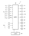
- FIG. 5 is a block diagram illustrating an electrical configuration of the vehicle air conditioner according to the embodiment.
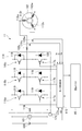
- FIG. 6 is a block diagram illustrating an electrical configuration of the electric compressor according to the embodiment.
- FIG. 1 is a block diagram illustrating a refrigerant flow in a cooling operation mode together with the overall configuration of the vehicle air conditioner according to the embodiment.
- FIG. 2 is a block diagram showing the refrigerant flow in the first heating
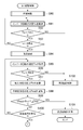
- FIG. 7 is a flowchart illustrating a processing procedure of electric motor drive control executed by the motor control unit of the embodiment.
- FIG. 8 is a flowchart illustrating a processing procedure of first activation control executed by the motor control unit of the embodiment.
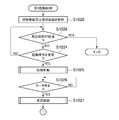
- FIG. 9 is a flowchart illustrating a processing procedure of second activation control executed by the motor control unit of the embodiment.
- FIG. 10 is a flowchart illustrating a processing procedure of first activation control executed by a motor control unit according to another embodiment.
- FIG. 11 is a flowchart illustrating a processing procedure of second activation control executed by a motor control unit according to another embodiment.
- the vehicle air conditioner 1 of this embodiment shown in FIGS. 1 to 3 is applied to a hybrid vehicle that obtains driving force for vehicle travel from an internal combustion engine (engine) and a travel electric motor.
- the vehicle air conditioner 1 includes a heat pump cycle 10 and an indoor air conditioning unit 30.
- the heat pump cycle 10 cools or heats the indoor air blown in the vehicle air conditioner 1 as an air conditioner.
- the indoor blown air is air blown into the vehicle interior.
- any one of the refrigerant circuits shown in FIGS. 1 to 3 can be selected.
- the refrigerant circuit shown in FIG. 1 is a refrigerant circuit that is used in a cooling operation mode in which indoor air is cooled to cool the passenger compartment.
- the refrigerant circuit shown in FIGS. 2 and 3 is a refrigerant circuit used in each of the first heating operation mode and the second heating operation mode in which the interior air is heated to heat the vehicle interior.
- the first heating operation mode is executed when the outside air temperature is extremely low, for example, 0 [° C.] or less.
- the second heating operation mode is a normal heating operation mode.
- the heat pump cycle 10 employs a normal chlorofluorocarbon refrigerant as a refrigerant, and constitutes a vapor compression subcritical refrigeration cycle in which the pressure of the high-pressure refrigerant does not exceed the critical pressure of the refrigerant.
- the heat pump cycle 10 of the present embodiment includes an electric compressor 11, an indoor condenser 12, a first decompressor 13, a gas-liquid separator 14, an intermediate pressure refrigerant flow path 15, an intermediate pressure on-off valve 16, A second decompressor 17, an outdoor heat exchanger 18, a third decompressor 20, a three-way valve 21, an indoor evaporator 22, an accumulator 23, and a second bypass channel 24 are provided.
- the electric compressor 11 sucks the refrigerant in the heat pump cycle 10, compresses it, and discharges it.
- the electric compressor 11 has a compression chamber 11a, a suction port 11b, a discharge port 11c, and an intermediate pressure port 11d.
- the compression chamber 11a compresses the low-pressure refrigerant sucked from the suction port 11b and discharges it from the discharge port 11c as a high-pressure refrigerant.
- the intermediate pressure port 11d guides the intermediate pressure refrigerant to the compression chamber 11a and joins the refrigerant in the middle of the compression process.
- the intermediate pressure refrigerant means a refrigerant having a pressure ranging from the pressure of the low-pressure refrigerant sucked into the compression chamber 11a to the pressure of the high-pressure refrigerant discharged from the compression chamber 11a.
- the electric compressor 11 includes a compression unit 111, an electric motor 112, and a housing 113.
- the compression unit 111 compresses the refrigerant in the compression chamber 11 a of the electric compressor 11.
- the compression unit 111 includes a scroll type compression mechanism.
- the compression part 111 may consist of other compression mechanisms, such as a vane type compression mechanism.
- the electric motor 112 drives the compression unit 111 to rotate.
- the electric motor 112 is a three-phase AC motor.
- the compression unit 111 and the electric motor 112 are accommodated in the housing 113.
- the housing 113 is provided with a suction port 11b, a discharge port 11c, and an intermediate pressure port 11d.
- the refrigerant flowing in the housing 113 flows from the suction port 11b toward the discharge port 11c.
- the intermediate pressure port 11d communicates with a location in the middle of the compression process of the compression chamber 11a.
- the electric compressor 11 of the present embodiment compresses the low-pressure refrigerant sucked from the suction port 11b by the compression unit 111 to generate high-pressure refrigerant, and discharges the high-pressure refrigerant from the discharge port 11c. Moreover, the electric compressor 11 flows in the intermediate pressure refrigerant from the intermediate pressure port 11d and joins the refrigerant in the middle of the compression process.
- the low-pressure refrigerant sucked from the suction port 11b is also referred to as suction refrigerant.
- the high-pressure refrigerant discharged from the discharge port 11c is also referred to as discharge refrigerant.
- the refrigerant sucked from the intermediate pressure port 11d is also referred to as an intermediate pressure refrigerant.
- the indoor condenser 12 has a refrigerant inlet side connected to a discharge port 11c of the electric compressor 11.
- the indoor condenser 12 is disposed in the casing 31 of the indoor air conditioning unit 30.
- the indoor condenser 12 serves as a heat exchanger that radiates the high-pressure refrigerant by heat-exchanging the high-pressure refrigerant discharged from the electric compressor 11 with the indoor blowing air and heats the indoor blowing air that has passed through the indoor evaporator 22. Function.
- the refrigerant inlet side of the first pressure reducer 13 is connected to the refrigerant outlet side of the indoor condenser 12.
- the first decompressor 13 decompresses the refrigerant flowing out from the indoor condenser 12 in the first heating operation mode until it becomes an intermediate pressure refrigerant.
- the 1st pressure reduction device 13 pressure-reduces the refrigerant
- the first pressure reducer 13 is an electric expansion valve. That is, the first pressure reducer 13 is an electric variable throttle mechanism configured to include a valve body configured to change the throttle opening degree and an electric actuator that changes the throttle opening degree of the valve body. is there.
- the refrigerant inlet side of the gas-liquid separator 14 is connected to the refrigerant outlet side of the first decompressor 13.
- the gas-liquid separator 14 separates the gas phase and the liquid phase of the refrigerant that has passed through the first pressure reducer 13.
- the gas-liquid separator 14 of the present embodiment is a centrifugal type that separates the refrigerant into a gas phase and a liquid phase by the action of centrifugal force.
- An intermediate pressure refrigerant flow path 15 is connected to the gas-phase refrigerant outlet side of the gas-liquid separator 14.
- the refrigerant inlet side of the second decompressor 17 is connected to the liquid phase refrigerant outlet side of the gas-liquid separator 14.
- the intermediate pressure refrigerant flow path 15 is a refrigerant flow path for guiding the gas-phase refrigerant separated by the gas-liquid separator 14 to the intermediate pressure port 11d of the electric compressor 11.
- the intermediate pressure refrigerant flow path 15 includes a refrigerant pipe 151 and a muffler 152.
- the muffler 152 is composed of a flow path forming member having a capacity larger than that of the refrigerant pipe 151 in order to reduce the pulsation of the refrigerant in the intermediate pressure refrigerant flow path 15.
- the intermediate pressure on / off valve 16 is provided in the middle of the intermediate pressure refrigerant flow path 15.
- the intermediate pressure on / off valve 16 is an on / off valve that opens and closes the intermediate pressure refrigerant flow path 15.
- the intermediate pressure on / off valve 16 of the present embodiment is an electromagnetic valve whose opening / closing operation is controlled based on a control signal.
- the intermediate pressure on-off valve 16 forms a refrigerant circuit in a two-stage compression mode for introducing the intermediate pressure refrigerant into the intermediate pressure port 11d of the electric compressor 11 by being opened in the first heating operation mode. Further, the intermediate pressure on-off valve 16 prohibits the flow of the intermediate pressure refrigerant into the intermediate pressure refrigerant flow path 15 by being closed during the first heating operation mode.
- the second decompressor 17 has a fixed throttle 171, a first bypass flow path 172, and an on-off valve 173.
- the fixed throttle valve 171 depressurizes the refrigerant.
- a nozzle, an orifice, or the like having a fixed throttle opening degree can be employed.
- the first bypass channel 172 is a coolant channel that guides the refrigerant that has flowed out of the gas-liquid separator 14 to the outdoor heat exchanger 18 side by bypassing the fixed throttle 171.
- the on-off valve 173 is an electromagnetic valve that opens and closes the first bypass flow path 172.
- the open / close valve 173 can be opened and closed to change to a throttle state in which the pressure reducing action of the fixed throttle 171 is exerted and a fully open state in which the pressure reducing action of the fixed throttle 171 is not exerted.
- the second pressure reducer 17 reduces the pressure of the intermediate-pressure liquid phase refrigerant separated by the gas-liquid separator 14 until it becomes a low-pressure refrigerant by being in the throttle state during the first heating operation mode.
- the 2nd pressure reduction device 17 will be in the state which does not exhibit a pressure reduction effect with respect to a refrigerant
- the refrigerant inlet side is connected to the refrigerant outlet side of the second decompressor 17.
- the outdoor heat exchanger 18 is disposed inside the vehicle bonnet, that is, outside the vehicle compartment.
- the outdoor heat exchanger 18 exchanges heat between the refrigerant flowing through the outdoor heat exchanger 18 and the air outside the vehicle that is blown by the blower fan 19.
- the outdoor heat exchanger 18 functions as an evaporator that evaporates the refrigerant in the first heating operation mode and the second heating operation mode to exert a heat absorption action.
- the outdoor heat exchanger 18 functions as a radiator that radiates high-pressure refrigerant in the cooling operation mode.
- the refrigerant inlet side of the third decompressor 20 is connected to the refrigerant outlet side of the outdoor heat exchanger 18.
- the third decompressor 20 decompresses the refrigerant that flows out of the outdoor heat exchanger 18 and flows into the indoor evaporator 22 in the cooling operation mode.
- the third pressure reducer 20 is composed of an electric expansion valve in the same manner as the first pressure reducer 13.
- the refrigerant inlet side of the three-way valve 21 is connected to the refrigerant outlet side of the third decompressor 20.
- Each of the two refrigerant outlets of the three-way valve 21 is connected to the refrigerant inlet side of the indoor evaporator 22 and the refrigerant inlet side of the accumulator 23.
- the three-way valve 21 has a refrigerant flow path for guiding the refrigerant flowing out from the third pressure reducer 20 to the indoor evaporator 22, and a second for guiding the refrigerant flowing out from the third pressure reducer 20 to the accumulator 23 by bypassing the indoor evaporator 22. Switch to bypass channel 24.
- the indoor evaporator 22 is disposed upstream of the indoor condenser 12 in the casing 31 of the indoor air conditioning unit 30.
- the indoor evaporator 22 is a heat exchanger that absorbs heat and evaporates the refrigerant by exchanging heat between the refrigerant circulating in the interior and the indoor blowing air during the cooling operation mode, and cools the indoor blowing air by the heat absorption action. .
- the accumulator 23 has the refrigerant inlet side connected to the refrigerant outlet side of the indoor evaporator 22 and the second bypass flow path 24.
- the accumulator 23 is a gas-liquid separator that separates the gas-liquid flowing into the accumulator 23 and stores excess refrigerant in the cycle.
- a suction port 11 b of the electric compressor 11 is connected to the gas phase refrigerant outlet of the accumulator 23.
- the indoor air conditioning unit 30 blows the temperature of the room blown air into the vehicle interior.
- the indoor air conditioning unit 30 is disposed inside an instrument panel provided in the foremost part of the vehicle interior.
- the indoor air conditioning unit 30 includes a casing 31, a blower 32, the indoor condenser 12, and the indoor evaporator 22.
- An inside / outside air switching device 33 is arranged on the most upstream side of the air flow of the indoor blast air in the casing 31.
- the inside / outside air switching device 33 switches between inside air and outside air as the air introduced into the casing 31.
- the inside air is the air in the passenger compartment. Outside air is outside the passenger compartment.
- a blower 32 that blows air sucked through the inside / outside air switching device 33 toward the vehicle interior is disposed on the downstream side of the air flow of the inside / outside air switching device 33.
- the blower 32 is an electric blower that drives a centrifugal multiblade fan with an electric motor.
- a bypass passage 34 is formed in the casing 31.
- the bypass passage 34 is a passage through which the indoor blown air that has passed through the indoor evaporator 22 flows while bypassing the indoor condenser 12.
- An air passage switching door 35 is disposed downstream of the indoor evaporator 22 and upstream of the indoor condenser 12.
- the air passage switching door 35 switches between an air passage that passes through the indoor condenser 12 and a bypass passage 34 as an air passage through which the indoor blown air that has passed through the indoor evaporator 22 flows.
- the vehicle air conditioner 1 includes a sensor group 41 for air conditioning control.
- the sensor group 41 includes an inside air sensor 41a, an outside air sensor 41b, a solar radiation sensor 41c, an evaporator temperature sensor 41d, a suction pressure sensor 41e, a discharge pressure sensor 41f, an intermediate pressure sensor 41g, and the like.
- the inside air sensor 41a detects the vehicle interior temperature Tin.
- the outside air sensor 41b detects the outside air temperature Tout.
- the solar radiation sensor 41c detects the solar radiation amount Sr in the passenger compartment.
- the evaporator temperature sensor 41d detects the temperature Te of the indoor evaporator 22.
- the suction pressure sensor 41e detects the pressure Pin of the suction refrigerant of the electric compressor 11.
- the discharge pressure sensor 41 f detects the pressure Pout of the refrigerant discharged from the electric compressor 11.
- the intermediate pressure sensor 41 g detects the pressure Pmid of the intermediate pressure refrigerant of the electric compressor 11.
- the vehicle air conditioner 1 includes an operation switch 42.
- the operation switch 42 is disposed on an operation panel disposed near the instrument panel, for example.
- the operation switch 42 includes an operation switch of the vehicle air conditioner 1, a vehicle interior temperature setting switch for setting the vehicle interior temperature, a selection switch for selecting a cooling operation mode and a heating operation mode, and the like.
- the operation switch 42 outputs an operation signal corresponding to the operation.
- the detection signal of the sensor group 41 and the operation signal of the operation switch 42 are taken in an air conditioning ECU (Electronic Control Unit) 40.
- the air conditioning ECU 40 is an electronic control device that includes a known microcomputer having a CPU, a ROM, a RAM, and the like and peripheral circuits thereof.
- the air conditioning ECU 40 is based on the detection signal of the sensor group 41 and the operation signal of the operation switch 42, and the electric compressor 11, the first pressure reducer 13, the intermediate pressure on / off valve 16, the on / off valve 173, the blower fan 19, and the third pressure reducer. 20, the drive of various apparatuses, such as the three-way valve 21, the air blower 32, and the air path switching door 35, is controlled.
- the air conditioning ECU 40 is electrically connected to the host ECU 50 so as to communicate with each other.
- the host ECU 50 is an electronic control device that controls the traveling system of the vehicle. More specifically, the host ECU 50 controls a main machine such as a motor and an engine based on a depression amount of an accelerator pedal (not shown) and controls power supply from a battery mounted on the vehicle to the main machine.
- the host ECU 50 outputs a stop signal for the electric compressor 11 to the air conditioning ECU 40 when it is necessary to secure power during vehicle acceleration.
- the air conditioning ECU 40 transmits a stop signal to the electric compressor 11 when receiving the stop signal transmitted from the host ECU 50. Thereby, the electric compressor 11 stops.
- the air conditioning ECU 40 transmits an activation signal to the electric compressor 11 when the electric compressor 11 is activated based on an operation signal of the operation switch 42 or the like. Thereby, the electric compressor 11 is started.
- the air conditioning ECU 40 performs normal operation control for controlling various devices according to any one of the cooling operation mode, the first heating operation mode, and the second heating operation mode.
- the air conditioning ECU 40 receives a stop signal for the electric compressor 11 from the host ECU 50, the air conditioning ECU 40 temporarily transmits the stop signal to the electric compressor 11 with priority over the normal operation control, thereby temporarily setting the electric compressor 11. Stop.
- the air conditioning ECU 40 switches the heat pump cycle 10 to the refrigerant circuit of each operation mode, and controls the operation of various devices so that a desired air conditioning state is obtained in each operation mode.
- Air-cooling operation mode The air-cooling operation mode is started when the air-cooling operation mode is selected by the selection switch with the operation switch of the operation panel turned on, for example.
- the air conditioning ECU 40 opens the first pressure reducer 13 and places the third pressure reducer 20 in the throttle state. That is, the first pressure reducer 13 does not exert a pressure reducing action, and the third pressure reducer 20 exerts a pressure reducing action. Further, the second pressure reducer 17 is fully opened by opening the on-off valve 173. That is, the second pressure reducer 17 does not exert a pressure reducing action. Further, the intermediate pressure on-off valve 16 is closed, and the second bypass flow path 24 side of the three-way valve 21 is closed.
- the air conditioning ECU 40 calculates a target blowing temperature TAO that is a target temperature of air blown into the vehicle interior based on the detection signal of the sensor group 41 and the operation signal of the operation panel.
- the air conditioning ECU 40 determines the operating states of various devices such as the electric compressor 11, the blower 32, and the air passage switching door 35 based on the calculated target blowing temperature TAO and the detection signal of the sensor group 41, and the determined operating state and Such a control signal is output to each device.
- the air conditioning ECU 40 operates the electric compressor 11 and the blower 32 at desired rotational speeds, for example, and sets the door position of the inside / outside air switching device 33 and the position of the air passage switching door 35 to desired positions.
- the specific position of the air passage switching door 35 is a position where the air passage of the indoor condenser 12 is closed, in other words, a position where all the blown air after passing through the indoor evaporator 22 passes through the bypass passage 34.
- the heat pump cycle 10 is switched to the refrigerant circuit in the cooling operation mode in which the refrigerant flows as shown by the thick line and the arrow in FIG. That is, the refrigerant discharged from the discharge port 11c of the electric compressor 11 is converted into the indoor condenser 12, the first decompressor 13, the gas-liquid separator 14, the second decompressor 17, the outdoor heat exchanger 18, and the third decompressor. 20, the indoor evaporator 22, and the accumulator 23 flow in this order and flow into the suction port 11 b of the electric compressor 11.
- the high-pressure refrigerant discharged from the discharge port 11c of the electric compressor 11 exchanges heat with the outside air in the outdoor heat exchanger 18 to radiate heat.
- the refrigerant that has flowed out of the outdoor heat exchanger 18 is decompressed and expanded by the third decompressor 20 until it becomes a low-pressure refrigerant, and the indoor evaporator 22 absorbs heat from the indoor blown air blown from the blower 32 and evaporates. Thereby, indoor ventilation air is cooled.
- the air passage of the indoor condenser 12 is closed by the air passage switching door 35, the high-pressure refrigerant that has flowed into the indoor condenser 12 does not substantially radiate heat to the indoor blown air, and from the indoor condenser 12. leak. Therefore, the indoor blown air cooled by the indoor evaporator 22 is blown out into the vehicle interior.
- the heating operation mode is started when, for example, the heating operation mode is selected by the selection switch while the operation switch of the operation panel is turned on.
- the first heating operation mode is executed when the outside air temperature is extremely low
- the second heating operation mode is executed when the outside air temperature is other than the extremely low temperature.
- the air conditioning ECU 40 executes the first heating operation mode when the detected temperature of the outside air sensor 41b is a reference temperature, for example, 0 [° C.] or less, and performs the second heating when the detected temperature of the outside air sensor 41b exceeds the reference temperature. Run the operation mode.
- (B1) First Heating Operation Mode As shown in FIG. 2, in the first heating operation mode, the air conditioning ECU 40 places the first pressure reducer 13 in the throttle state and the third pressure reducer 20 in the fully open state. In addition, the second decompressor 17 is brought into the throttle state by closing the on-off valve 173. Further, the intermediate pressure on-off valve 16 is opened, and the second bypass flow path 24 side of the three-way valve 21 is opened.
- the air conditioning ECU 40 determines the operating state of various devices based on the target blowout temperature TAO and the like, and outputs a control signal that makes the determined operating state to each device.
- the air passage switching door 35 becomes a position where the bypass passage 34 is closed, in other words, a position where all the blown air after passing through the indoor evaporator 22 passes through the indoor condenser 12.
- the refrigerant circuit in the first heating operation mode is a gas injection cycle. That is, the high-pressure refrigerant discharged from the discharge port 11 c of the electric compressor 11 is condensed by the indoor condenser 12, and the condensed high-pressure refrigerant is decompressed by the first decompressor 13 until it becomes intermediate-pressure refrigerant.
- the intermediate pressure refrigerant flowing out from the first pressure reducer 13 is separated into a gas phase refrigerant and a liquid phase refrigerant by the gas-liquid separator 14.
- the intermediate-pressure liquid-phase refrigerant separated by the gas-liquid separator 14 is decompressed by the second decompressor 17 until it becomes a low-pressure refrigerant, then evaporated by the outdoor heat exchanger 18, and electrically driven through the accumulator 23.
- the air is sucked into the suction port 11b of the compressor 11.
- the intermediate-pressure gas-phase refrigerant separated by the gas-liquid separator 14 is guided to the intermediate-pressure port 11d of the electric compressor 11 via the intermediate-pressure refrigerant flow path 15, and joins the refrigerant in the middle of the compression process. To do.
- the first heating operation mode corresponds to the two-stage compression mode in which the intermediate pressure refrigerant is introduced into the compression unit 111 of the electric compressor 11.
- the indoor blown air is not cooled by the indoor evaporator 22.
- the indoor blown air that has passed through the indoor evaporator 22 is heated by the indoor condenser 12 by heat exchange with the high-pressure refrigerant and blown out into the vehicle interior.
- (B2) Second Heating Operation Mode As shown in FIG. 3, in the second heating operation mode, the air conditioning ECU 40 places the first pressure reducer 13 in the throttle state and the third pressure reducer 20 in the fully open state. Further, the second pressure reducer 17 is fully opened by opening the on-off valve 173. Further, the intermediate pressure on / off valve 16 is closed and the second bypass flow path 24 side of the three-way valve 21 is opened.
- the air conditioning ECU 40 determines the operating state of various devices based on the target blowing temperature TAO and the like, and outputs a control signal that makes the determined operating state to each device.
- the heat pump cycle 10 is switched to the refrigerant circuit in the second heating operation mode in which the refrigerant flows as shown by the thick line and the arrow in FIG. That is, the high-pressure refrigerant discharged from the discharge port 11 c of the electric compressor 11 is condensed by the indoor condenser 12, and the condensed high-pressure refrigerant is decompressed by the first decompressor 13 until it becomes low-pressure refrigerant.
- the low-pressure refrigerant that has flowed out of the first pressure reducer 13 flows into the gas-liquid separator 14.
- the intermediate pressure on-off valve 16 since the intermediate pressure on-off valve 16 is closed, the low-pressure refrigerant that has flowed into the gas-liquid separator 14 does not flow into the intermediate-pressure refrigerant flow path 15 but flows into the outdoor heat exchanger 18.
- the refrigerant flowing into the outdoor heat exchanger 18 is evaporated by the heat exchanger with the outside air, and is sucked into the suction port 11b of the electric compressor 11 through the accumulator 23.
- the indoor blown air is not cooled by the indoor evaporator 22.
- the indoor blown air that has passed through the indoor evaporator 22 is heated by the indoor condenser 12 by heat exchange with the high-pressure refrigerant and blown out into the vehicle interior.
- the cooling operation mode and the second heating operation mode correspond to a one-stage compression mode in which intermediate pressure refrigerant is not introduced into the compression unit 111 of the electric compressor 11.
- the electric compressor 11 includes an inverter circuit 114 and a motor control unit 115.
- the inverter circuit 114 corresponds to a motor drive circuit.
- the inverter circuit 114 includes upper arm switching elements 116a to 116c, lower arm switching elements 117a to 117c, and a current smoothing capacitor 118.
- a diode 119 is connected to the upper arm switching elements 116a to 116c and the lower arm switching elements 117a to 117c.
- the diode 119 circulates the back electromotive force generated in the electric motor 112 to the battery 120 of the DC power source mounted on the vehicle.
- the base sides of the upper arm switching elements 116 a to 116 c and the lower arm switching elements 117 a to 117 c are connected to the motor control unit 115.
- the collector side of the switching elements 116 a to 116 c of the upper arm is connected to the high potential side terminal of the battery 120.
- the emitter sides of the upper arm switching elements 116a to 116c are connected to the U-phase coil 112u, the V-phase coil 112v, and the W-phase coil 112w of the electric motor 112, respectively.
- the emitter side of the switching elements 117 a to 117 c in the lower arm is connected to the low potential side terminal of the battery 120.
- the collector side of the switching elements 117a to 117c of the lower arm is connected to the phase coils 112u to 112w, respectively.
- the switching elements 116 a to 116 c and 117 a to 117 c are turned on / off based on the PWM drive signal transmitted from the motor control unit 115, thereby generating three-phase AC power from the DC power of the battery 120.
- the three-phase AC power generated by the inverter circuit 114 is supplied to the phase coils 112u to 112w of the electric motor 112, whereby a rotating magnetic field is formed by the phase coils 112u to 112w.
- the rotating magnetic field acts on a rotor having a permanent magnet or the like, whereby the rotor 112r rotates.
- the compressor 111 is rotated based on the rotation of the rotor 112r, whereby the electric compressor 11 compresses the refrigerant.
- the electric compressor 11 is provided with a voltage sensor 121, current sensors 122u to 122w, and a temperature sensor 123.
- Voltage sensor 121 detects voltage value VB of battery 120.
- Current sensors 122u to 122w detect respective phase current values Iu to Iw supplied from inverter circuit 114 to electric motor 112.
- the temperature sensor 123 detects the temperature Tiv of the inverter circuit 114. Output signals of the sensors 121, 122u to 122w, 123 are taken into the motor control unit 115.
- the air conditioning ECU 40 sets the target rotation speed of the electric compressor 11, that is, the target rotation speed of the rotor 112r, based on the detection signal of the sensor group 41 and the operation signal of the operation switch 42, and sets the set target rotation speed to the motor. It transmits to the control part 115.
- the motor control unit 115 is an electronic control device configured by a known microcomputer having a CPU, a ROM, a RAM, and the like and its peripheral circuits.
- the motor control unit 115 estimates the rotational speed of the rotor 112r based on the voltage value VB of the battery 120 detected by the voltage sensor 121 and the phase current values Iu to Iw detected by the current sensors 122u to 122w.
- the motor control unit 115 generates a PWM drive signal by executing feedback control that causes the estimated rotation speed to follow the target rotation speed.
- the motor control unit 115 performs PWM control of the electric motor 112 by outputting this PWM drive signal to the switching elements 116a to 116c and 117a to 117c of the inverter circuit 114.
- the rotational speed of the rotor 112r is controlled so as to follow the target rotational speed. That is, the motor control unit 115 performs so-called sensorless control that performs rotation control of the rotor 112r without using a rotation sensor that detects the rotation position of the rotor 112r.
- the motor control unit 115 repeatedly executes the process shown in FIG. 7 at a predetermined cycle.
- the motor control unit 115 first determines whether or not an activation signal transmitted from the air conditioning ECU 40 has been received as the process of step S ⁇ b> 1. If the determination in step S1 is affirmative, the motor control unit 115 estimates the initial position of the rotor 112r as the process in step S2. For example, the motor control unit 115 drives the inverter circuit 114 so that a high-frequency voltage is applied to the phase coils 112u to 112w of the electric motor 112. The motor control unit 115 estimates the initial rotational position of the rotor 112r based on the phase current values Iu to Iw detected by the current sensors 122u to 122w when a high frequency voltage is applied to the phase coils 112u to 112w. .
- the motor control unit 115 activates the electric motor 112 as a process of step S3 following the process of step S2. Specifically, the motor control unit 115 forms a rotating magnetic field that can rotate the rotor 112r by each of the phase coils 112u to 112w with reference to the initial rotation position of the rotor 112r obtained in the process of step S2. Thus, the inverter circuit 114 is driven. Thereby, the rotor 112r rotates and the electric motor 112 is started.
- the motor control unit 115 determines whether or not the rotation speed of the rotor 112r has reached a specified rotation speed as the process of step S4 following the process of step S3. Specifically, the motor control unit 115 estimates the rotational speed of the rotor 112r based on the voltage value VB of the battery 120 and the respective phase current values Iu to Iw, and the estimated rotational speed of the rotor 112r becomes the specified rotational speed. Determine whether it has been reached.
- the specified rotational speed is set in advance through experiments or the like so that it can be determined whether or not the rotational speed of the rotor 112r has increased to a rotational speed at which sensorless control can be stably executed.
- step S4 When the motor control unit 115 makes a positive determination in step S4, the motor control unit 115 performs normal control of the electric motor 112 as step S5.
- the normal control of this embodiment corresponds to sensorless control of the electric motor 112.
- the motor control unit 115 determines whether or not a stop signal transmitted from the air conditioning ECU 40 has been received as the process of step S6 during execution of the normal control of the electric motor 112. If the determination in step S6 is affirmative, the motor control unit 115 determines whether the heat pump cycle 10 is driven in the two-stage compression mode as the process in step S7. Specifically, the motor control unit 115 acquires information on whether or not the heat pump cycle 10 is driven in the two-stage compression mode from the air conditioning ECU 40, and executes the process of step S7 based on the acquired information.
- the motor control unit 115 makes a negative determination in step S7 when the heat pump cycle 10 is not driven in the two-stage compression mode, that is, when the heat pump cycle 10 is driven in the one-stage compression mode. In this case, the motor control unit 115 normally stops the electric motor 112 as the process of step S8. That is, the motor control unit 115 stops the electric motor 112 by stopping the power supply to the electric motor 112.
- step S7 When the motor control unit 115 makes an affirmative determination in the process of step S7, the first control is executed as the process of step S9.
- the processing procedure of the first activation control is as shown in FIG.
- the motor control unit 115 first short-circuits the electric motor 112 as a process of step S90. Specifically, the motor control unit 115 turns on all the switching elements 116a to 116c of the upper arm of the inverter circuit 114 and turns off all of the switching elements 117a to 117c of the lower arm. Alternatively, the motor control unit 115 turns off all the switching elements 116a to 116c in the upper arm of the inverter circuit 114 and turns on all the switching elements 117a to 117c in the lower arm.
- the motor control unit 115 acquires the temperature Tiv of the inverter circuit 114 by the temperature sensor 123 as the process of step S91 following the process of step S90. Further, the motor control unit 115 determines whether or not the temperature Tiv of the inverter circuit 114 is lower than the temperature threshold Tth1 as the process of step S92 following the process of step S91.
- the temperature threshold value Tth1 is set in advance by experiments or the like so that it can be determined whether or not the inverter circuit 114 may be damaged by the heat generated in the inverter circuit 114 when the electric motor 112 is subjected to short-circuit braking. Has been. In the present embodiment, this temperature threshold value Tth1 corresponds to a temperature threshold value during short-circuit braking.
- step S92 determines whether the rotor 112r has stopped as the processing in step S93. Specifically, the motor control unit 115 determines whether the rotor 112r has stopped based on the rotational speed of the rotor 112r estimated from the voltage value VB of the battery 120 and the phase current values Iu to Iw. If the motor control unit 115 makes an affirmative determination in step S92 and a negative determination in step S93, the motor control unit 115 returns to step S91.
- the motor control unit 115 makes an affirmative determination in the process of step S93, the electric motor 112 is DC-excited as a process of step S94. Specifically, the motor control unit 115 drives the inverter circuit 114 so that a unidirectional magnetic field is formed by direct current excitation, and fixes the rotor 112r to a specific phase. Thereby, the rotational position of the rotor can be fixed at a predetermined rotational position corresponding to a unidirectional magnetic field formed by DC excitation.
- the motor control unit 115 acquires the temperature Tiv of the inverter circuit 114 by the temperature sensor 123 as the process of step S95 following the process of step S94. Moreover, the motor control part 115 judges whether the temperature Tiv of the inverter circuit 114 is less than the temperature threshold value Tth2 as a process of step S96 following step S95.
- the temperature threshold value Tth2 is set in advance by experiments or the like so that it can be determined whether or not the inverter circuit 114 may be damaged by the heat generated in the inverter circuit 114 when the electric motor 112 is DC-excited. Has been. In the present embodiment, this temperature threshold value Tth2 corresponds to the temperature threshold value during DC excitation.
- step S96 When the motor control unit 115 makes an affirmative determination in the process of step S96, that is, when it can be determined that heat damage does not occur in the inverter circuit 114, the electric compressor is processed as a process of steps S97 and S98.
- the information on the pressure Pin 11 of the suction refrigerant 11 and the pressure Pmid of the intermediate pressure refrigerant is acquired from the air conditioning ECU 40.
- step S99 the motor control unit 115 calculates a difference (Pmid ⁇ Pin) between the pressure Pin of the intake refrigerant and the pressure Pmid of the intermediate pressure refrigerant, and the pressure difference (Pmid ⁇ Pin) is predetermined. It is determined whether or not the pressure threshold value Pth is less than or equal to.
- the pressure threshold value Pth is set in advance by experiments or the like so that it can be determined whether or not the pressure Pmid of the intermediate pressure refrigerant has decreased to a pressure that does not reversely rotate the rotor 112r.
- step S99 determines whether or not an activation signal transmitted from the air conditioning ECU 40 has been received as the process of step S100. If the motor control unit 115 makes a negative determination in step S100, it returns to step S95. That is, the motor control unit 115 returns to the process of step S95 when the activation signal cannot be received in a situation where the rotor 112r may rotate in the reverse direction.
- step S100 If the motor control unit 115 makes an affirmative determination in step S100, that is, if it receives a start signal in a situation where the rotor 112r may rotate in the reverse direction, the motor control unit 115 proceeds to step S3 shown in FIG. Returning, the electric motor 112 is started. In this case, the motor control unit 115 activates the electric motor 112 by forming a rotating magnetic field by the phase coils 112u to 112w with reference to a predetermined rotation position of the rotor 112r fixed by DC excitation.
- step S99 shown in FIG. 8 If the determination in step S99 shown in FIG. 8 is affirmative, that is, if there is no possibility that the rotor 112r rotates in the reverse direction, the motor control unit 115 stops the DC excitation of the electric motor 112 as the processing in step S101. Then, a series of processing ends.
- step S92 If the negative determination is made in the process of step S92 or the process of step S96, that is, if there is a possibility that damage due to heat may occur in the inverter circuit 114, the motor control unit 115 performs the second process as the process of step S102. Execute startup control. The processing procedure of the second activation control is as shown in FIG.
- the motor control unit 115 first cancels the short-circuit braking or the direct current excitation of the electric motor 112 as the process of step S1020.
- the motor control unit 115 performs short-circuit braking of the electric motor 112 when the second activation control is executed by making a negative determination in the process of step S92 shown in FIG. In this case, the motor control unit 115 cancels the short-circuit braking of the electric motor 112 as the process of step S1020.
- the motor control unit 115 performs DC excitation of the electric motor 112 when the second activation control is executed by making a negative determination in the process of step S96 shown in FIG. In this case, the motor control unit 115 cancels DC excitation of the electric motor 112 as the process of step S1020.
- the motor control unit 115 acquires, from the air conditioning ECU 40, information on the suction refrigerant pressure Pin and the intermediate pressure refrigerant pressure Pmid of the electric compressor 11 as the processing of steps S1021 and S1022 following the processing of step S1020.
- step S1023 the motor control unit 115 calculates a difference (Pmid ⁇ Pin) between the pressure Pin of the suction refrigerant and the pressure Pmid of the intermediate pressure refrigerant, and the pressure difference (Pmid ⁇ Pin) is the pressure. It is determined whether or not the threshold value Pth has been reached.
- step S1023 determines whether or not an activation signal transmitted from the air conditioning ECU 40 has been received as the process of step S1024. If the motor control unit 115 makes a negative determination in step S1024, it returns to step S1021. That is, the motor control unit 115 returns to the process of step S1021 when the activation signal cannot be received in a situation where the rotor 112r may rotate in the reverse direction.
- step S1023 When the motor control unit 115 makes an affirmative determination in the process of step S1023, that is, when there is no possibility that the rotor 112r rotates backward, the series of processes ends.
- step S1024 When the motor control unit 115 makes an affirmative determination in the process of step S1024, that is, when the activation signal is received in a situation where the rotor 112r may rotate backward, the process of step S1025 is the same as the process of step S90. Then, the electric motor 112 is short-circuit braked, and the electric motor 112 is stopped. The motor control unit 115 determines whether or not the rotor 112r has stopped as the process of step S1026 following step S1025, as in the process of step S93.
- step S1026 If the determination in step S1026 is affirmative, that is, if the rotor 112r is stopped, the motor control unit 115 performs DC excitation of the electric motor 112 as the processing in step S1027, as in the processing in step S94. Then, the motor control unit 115 returns to the process of step S3 shown in FIG. 7 and activates the electric motor 112. In this case, the motor control unit 115 activates the electric motor 112 by forming a rotating magnetic field by the phase coils 112u to 112w with reference to a predetermined rotation position of the rotor 112r fixed by DC excitation.
- the motor control unit 115 causes the electric motor 112 to be short-circuit braked to stop the rotation of the rotor 112r, and then DC-excites the electric motor 112.
- the rotational position of the rotor 112r is fixed at a predetermined rotational position.
- the motor control unit 115 cancels the short-circuit braking of the electric motor 112 when the temperature Tiv of the inverter circuit 114 becomes equal to or higher than the temperature threshold Tth1 while the electric motor 112 is short-circuited. Thereby, when the temperature of the inverter circuit 114 rises due to the short circuit braking of the electric motor 112, the short circuit braking of the electric motor 112 is released, so that damage due to heat generation of the inverter circuit 114 can be suppressed.
- the motor control unit 115 cancels the DC excitation of the electric motor 112 when the temperature Tiv of the inverter circuit 114 becomes equal to or higher than the temperature threshold Tth2 when the electric motor 112 is DC-excited.
- the temperature of the inverter circuit 114 rises due to the direct current excitation of the electric motor 112
- the direct current excitation of the electric motor 112 is released, so that damage due to heat generation of the inverter circuit 114 can be suppressed.
- the motor control unit 115 determines that the pressure Pmid of the intermediate pressure refrigerant Pmid is lower than the pressure threshold Pth based on the difference (Pmid ⁇ Pin) between the pressure Pin of the suction refrigerant and the pressure Pmid of the intermediate pressure refrigerant. It is determined that the pressure has decreased to a level that does not cause the rotor 112r to rotate backward. Thereby, it can be easily determined whether or not the pressure Pmid of the intermediate pressure refrigerant has decreased to a pressure that does not cause the rotor 112r to reversely rotate.
- the said embodiment can also be implemented with the following forms. Even if the motor control unit 115 determines that the pressure Pmid of the intermediate pressure refrigerant has decreased to a level that does not cause the rotor 112r to reversely rotate, based on the elapse of a predetermined time from the time when the DC excitation is performed. Good. In this case, for example, as shown in FIG. 10, the motor control unit 115 determines whether or not a predetermined time has elapsed since the point in time when the direct current excitation was executed as the process of step S103 instead of the process of step S99 shown in FIG. Execute the process to determine. Similarly, as shown in FIG.
- the motor control unit 115 performs a process of determining whether or not a predetermined time has elapsed from the time when the DC excitation is executed, instead of the process of step S ⁇ b> 1023 shown in FIG. 9. Execute. Even with such a configuration, it is possible to easily determine whether or not the pressure Pmid of the intermediate pressure refrigerant has decreased to a pressure that does not cause the rotor 112r to reversely rotate.
- the motor control unit 115 estimates the force acting in the reverse direction with respect to the rotor 112r based on information such as the phase current values Iu to Iw immediately before the electric motor 112 stops and the rotation speed of the rotor 112r.
- the predetermined time used in step S103 in FIG. 10 or step S1028 in FIG. 11 may be set based on the estimated reverse rotational force. That is, the motor control unit 115 may set the DC excitation execution time based on the estimated reverse rotational force. Similarly, the motor control unit 115 may set the execution time of the short-circuit braking based on the estimated reverse rotational force.
- the motor control unit 115 may set the magnitude of the excitation current of the electric motor 112 during direct current excitation based on the estimated reverse rotational force. In addition, the motor control unit 115 may reduce the magnitude of the excitation current of the electric motor 112 during DC excitation as time passes.
- the motor control unit 115 sets the heat pump cycle 10 to 2 based on information such as the phase current values Iu to Iw immediately before the electric motor 112 stops and the rotational speed of the rotor 112r. It may be determined whether or not the driving is performed in the stage compression mode.
- the means and / or functions provided by the motor control unit 115 can be provided by software stored in a substantial storage device and a computer that executes the software, only software, only hardware, or a combination thereof.
- the motor control unit 115 when it is provided by an electronic circuit that is hardware, it can be provided by a digital circuit including a large number of logic circuits or an analog circuit.
Landscapes
- Engineering & Computer Science (AREA)
- Mechanical Engineering (AREA)
- General Engineering & Computer Science (AREA)
- Physics & Mathematics (AREA)
- Thermal Sciences (AREA)
- Power Engineering (AREA)
- Air-Conditioning For Vehicles (AREA)
- Control Of Positive-Displacement Pumps (AREA)
- Applications Or Details Of Rotary Compressors (AREA)
- Control Of Motors That Do Not Use Commutators (AREA)
Abstract
電動圧縮機11は、吸入される低圧冷媒を圧縮して高圧冷媒を吐出する圧縮部111と、ロータの回転に基づき圧縮部111を駆動させる電動モータ112と、電動モータ112を駆動させるモータ駆動回路と、圧縮部111に中間圧冷媒を導入する中間圧ポート11dと、ロータの回転制御を行う制御部と、を備える。制御部は、中間圧冷媒が圧縮部111に導入される2段圧縮モードの実行時に電動モータ112を停止させる場合、電動モータ112を短絡制動させてロータの回転を停止させた後、ロータの回転位置を所定の回転位置で固定させるべく電動モータ112を直流励磁する。
Description
本出願は、2015年9月29日に出願された日本国特許出願2015-190688号に基づくものであって、その優先権の利益を主張するものであり、その特許出願の全ての内容が、参照により本明細書に組み込まれる。
本開示は、ガスインジェクションサイクルに用いられる電動圧縮機に関する。
特許文献1に記載の車両用空調装置では、エンジンの駆動力を利用して圧縮機を駆動させることにより冷媒を圧縮している。これに対し、近年、電気自動車やハイブリッド等の電動車両の普及により、車両に搭載される車両用空調装置では、電動モータで駆動する電動圧縮機が採用されている。例えばハイブリッド車両の場合、電動圧縮機が採用されることで、エンジンが停止している状況でも空調装置を作動させることができる。
電気自動車やハイブリッド車両等の電動車両に搭載される車両用空調装置において、電動モータにより駆動する電動圧縮機を用いると、下記の問題が発生するおそれがある。
まず、ガスインジェクションサイクルを構成する電動圧縮機は、圧縮部、圧縮部を駆動する電動モータ、吸入ポート、吐出ポート、及び中間圧ポートを有している。この電動圧縮機では、吸入ポートから吸入した低圧の吸入冷媒を圧縮部で圧縮して高圧の冷媒として吐出ポートから吐出するとともに、中間圧ポートからサイクル内の中間圧冷媒を流入させて圧縮過程途中の冷媒に合流される。この中間圧冷媒の流れる冷媒回路が、ガスインジェクションサイクルの冷媒回路である。ガスインジェクションサイクルは、二段圧縮サイクルとも称される。ガスインジェクションサイクルは、ヒートポンプサイクルの極低温下での暖房時における暖房能力の向上のために用いられる。したがって、このガスインジェクションサイクルでの運転モードは、極低温下での暖房運転時に実行される。以下、ガスインジェクションサイクルでの運転モードを2段圧縮モードと称する。
電動圧縮機は、車両に搭載された電源から給電されるため、車両電源から主機等の他の車両搭載機器へ供給する電力の確保を目的として、一時停止を要求される場合がある。しかしながら、2段圧縮モードでの暖房運転中に、電動圧縮機を一時停止させると、中間圧冷媒と吸入冷媒との圧力差により、中間圧ポートから吸入ポートに冷媒が逆流し、電動モータのロータが逆回転し続けてしまう。ロータが逆回転すると、電動圧縮機の停止要求が解除された後に電動モータを再起動させる際に、ロータの回転位置を推定することが難しくなり、結果的に電動モータの再起動時に脱調が生じるおそれがある。
なお、ロータの逆回転を抑制する方法として、モータ駆動回路の上アーム及び下アームの一方のアームのスイッチング素子をオンさせ、他方のアームのスイッチング素子をオフさせることにより、電動モータを短絡制動させることが考えられる。電動モータを短絡制動させることにより、ロータが逆回転している時間を短縮することができる。
しかしながら、短絡制動は、モータ駆動回路及びステータコイルの閉回路に電流が流れている状況、すなわちロータが回転している状況でしか発生しない。そのため、短絡制動によりロータの逆回転が一旦停止した場合でも、中間圧冷媒の圧力が、吸入冷媒の圧力に対してある程度大きいと、それらの圧力差により中間圧冷媒が吸入ポートに逆流し、ロータが逆回転してしまう。結局、中間圧冷媒の圧力と吸入冷媒の圧力との差が十分小さくなるまでロータの逆回転及び停止が繰り返される可能性がある。この場合、結果的にロータが逆回転してしまうため、電動モータの再起動時にロータの回転位置を特定することが難しくなり、電動モータの脱調を回避することができない。
本開示の目的は、再起動時における電動モータの脱調を抑制することのできる電動圧縮機を提供することにある。
本開示の一態様による電動圧縮機は、吸入される低圧冷媒を圧縮して高圧冷媒を吐出する圧縮部と、ロータの回転に基づき圧縮部を駆動させる電動モータと、電動モータを駆動させるモータ駆動回路と、圧縮部に中間圧冷媒を導入する中間圧ポートと、ロータの回転制御を行う制御部と、を備える。制御部は、中間圧冷媒が圧縮部に導入される2段圧縮モードの実行時に電動モータを停止させる場合、電動モータを短絡制動させてロータの回転を停止させた後、ロータの回転位置を所定の回転位置で固定させるべく電動モータを直流励磁する。
この構成によれば、2段圧縮モードの実行時に電動モータを停止させる際、短絡制動によりロータの回転が停止した後、直流励磁によりロータの回転位置が所定の回転位置で固定される。これにより、中間圧冷媒の圧力が吸入冷媒の圧力に対してある程度大きい場合でも、ロータの逆回転を抑制することができる。よって、再起動時における電動モータの脱調を抑制することができる。
以下、電動圧縮機の一実施形態について説明する。はじめに、本実施形態の電動圧縮機を用いた車両用空調装置の概要について説明する。
図1~図3に示される本実施形態の車両用空調装置1は、内燃機関(エンジン)及び走行用電動モータから車両走行用の駆動力を得るハイブリッド車両に適用されている。車両用空調装置1は、ヒートポンプサイクル10と室内空調ユニット30とを備えている。
ヒートポンプサイクル10は、車両用空調装置1において、空調対象である室内送風空気を冷却あるいは加熱する。室内送風空気は、車室内に送風される空気である。ヒートポンプサイクル10では、図1~図3に示される冷媒回路のいずれかに選択可能である。図1に示される冷媒回路は、室内送風空気を冷却して車室内を冷房する冷房運転モードで用いられる冷媒回路である。図2及び図3に示される冷媒回路は、室内送風空気を加熱して車室内を暖房する第1暖房運転モード及び第2暖房運転モードでそれぞれ用いられる冷媒回路である。第1暖房運転モードは、外気温が極低温時、例えば0[℃]以下の時に実行される。第2暖房運転モードは、通常の暖房運転モードである。
ヒートポンプサイクル10は、冷媒として通常のフロン系冷媒を採用しており、高圧冷媒の圧力が冷媒の臨界圧力を超えない蒸気圧縮式の亜臨界冷凍サイクルを構成している。本実施形態のヒートポンプサイクル10は、電動圧縮機11と、室内凝縮器12と、第1減圧器13と、気液分離器14と、中間圧冷媒流路15と、中間圧開閉弁16と、第2減圧器17と、室外熱交換器18と、第3減圧器20と、三方弁21と、室内蒸発器22と、アキュームレータ23と、第2迂回流路24とを備えている。
電動圧縮機11は、ヒートポンプサイクル10において冷媒を吸入し、圧縮して吐出する。電動圧縮機11は、圧縮室11aと、吸入ポート11bと、吐出ポート11cと、中間圧ポート11dとを有している。圧縮室11aは、吸入ポート11bから吸入した低圧冷媒を圧縮して高圧冷媒として吐出ポート11cから吐出する。中間圧ポート11dは、中間圧冷媒を圧縮室11aに導くとともに、圧縮過程途中の冷媒に合流させる。中間圧冷媒とは、圧縮室11aに吸入される低圧冷媒の圧力から、圧縮室11aから吐出される高圧冷媒の圧力までの範囲の圧力を有する冷媒を意味する。
より詳しくは、図4に示されるように、電動圧縮機11は、圧縮部111と、電動モータ112と、ハウジング113とを有している。圧縮部111は、電動圧縮機11の圧縮室11a内の冷媒を圧縮する。圧縮部111は、スクロール式圧縮機構からなる。なお、圧縮部111は、ベーン型圧縮機構等の他の圧縮機構からなるものであってもよい。電動モータ112は、圧縮部111を回転駆動させる。電動モータ112は、三相交流モータからなる。圧縮部111及び電動モータ112は、ハウジング113の内部に収容されている。
ハウジング113には、吸入ポート11bと、吐出ポート11cと、中間圧ポート11dが設けられている。ハウジング113内を流れる冷媒は、吸入ポート11bから吐出ポート11cに向かって流れる。中間圧ポート11dは、圧縮室11aの圧縮過程途中の箇所と連通している。
このように、本実施形態の電動圧縮機11は、吸入ポート11bから吸入した低圧冷媒を圧縮部111で圧縮して高圧冷媒を生成し、この高圧冷媒を吐出ポート11cから吐出する。また、電動圧縮機11は、中間圧ポート11dから中間圧冷媒を流入させて圧縮過程途中の冷媒に合流させる。以下では、吸入ポート11bから吸入される低圧冷媒を、吸入冷媒とも称する。また、吐出ポート11cから吐出される高圧冷媒を、吐出冷媒とも称する。さらに、中間圧ポート11dから吸入される冷媒を、中間圧冷媒とも称する。
図1~図3に示されるように、室内凝縮器12は、その冷媒入口側が電動圧縮機11の吐出ポート11cに接続されている。室内凝縮器12は、室内空調ユニット30のケーシング31内に配置されている。室内凝縮器12は、電動圧縮機11から吐出された高圧冷媒を室内送風空気と熱交換させることにより高圧冷媒を放熱させるとともに、室内蒸発器22を通過した室内送風空気を加熱する熱交換器として機能する。
第1減圧器13は、その冷媒入口側が室内凝縮器12の冷媒出口側に接続されている。第1減圧器13は、第1暖房運転モード時に室内凝縮器12から流出する冷媒を中間圧冷媒となるまで減圧させる。また、第1減圧器13は、第2暖房運転モード時に室内凝縮器12から流出する冷媒を低圧冷媒となるまで減圧させる。第1減圧器13は、電気式膨張弁である。すなわち、第1減圧器13は、絞り開度を変更可能に構成された弁体と、この弁体の絞り開度を変化させる電動アクチュエータとを有して構成される電気式の可変絞り機構である。
気液分離器14は、その冷媒入口側が第1減圧器13の冷媒出口側に接続されている。気液分離器14は、第1減圧器13を通過した冷媒の気相及び液相を分離する。本実施形態の気液分離器14は、遠心力の作用によって冷媒を気相及び液相に分離する遠心分離式のものである。気液分離器14の気相冷媒出口側には、中間圧冷媒流路15が接続されている。気液分離器14の液相冷媒出口側には、第2減圧器17の冷媒入口側が接続されている。
中間圧冷媒流路15は、気液分離器14で分離された気相冷媒を電動圧縮機11の中間圧ポート11dに導くための冷媒流路である。中間圧冷媒流路15は、冷媒配管151と、マフラ152とを有している。マフラ152は、中間圧冷媒流路15内の冷媒の脈動を低減するために、冷媒配管151よりも容量の大きい流路形成部材により構成されている。
中間圧開閉弁16は、中間圧冷媒流路15の途中に設けられている。中間圧開閉弁16は、中間圧冷媒流路15を開閉する開閉弁である。本実施形態の中間圧開閉弁16は、制御信号に基づいて開閉動作が制御される電磁弁である。中間圧開閉弁16は、第1暖房運転モード時に開弁状態になることにより、中間圧冷媒を電動圧縮機11の中間圧ポート11dに導入する2段圧縮モードの冷媒回路を形成する。また、中間圧開閉弁16は、第1暖房運転モード時に閉弁状態になることにより、中間圧冷媒流路15への中間圧冷媒の流入を禁止する。
第2減圧器17は、固定絞り171と、第1迂回流路172と、開閉弁173とを有している。固定絞り弁171は冷媒を減圧させる。固定絞り弁171としては、絞り開度が固定されたノズルやオリフィス等を採用することができる。第1迂回流路172は、気液分離器14から流出した冷媒を固定絞り171を迂回させて室外熱交換器18側に導く冷媒流路である。開閉弁173は、第1迂回流路172を開閉する電磁弁である。第2減圧器17では、開閉弁173の開閉により、固定絞り171の減圧作用を発揮させる絞り状態と、固定絞り171の減圧作用を発揮させない全開状態とに変更することが可能となっている。第2減圧器17は、第1暖房運転モード時に絞り状態になることにより、気液分離器14にて分離された中間圧の液相冷媒を低圧冷媒になるまで減圧させる。また、第2減圧器17は、冷房運転モード時や第2暖房運転モード時に全開状態になることにより、冷媒に対して減圧作用を発揮しない状態になる。
室外熱交換器18は、その冷媒入口側が第2減圧器17の冷媒出口側に接続されている。室外熱交換器18は、車両ボンネット内、すなわち車室外に配置されている。室外熱交換器18は、その内部を流通する冷媒と、送風ファン19により送風される車室外空気とを熱交換させるものである。室外熱交換器18は、第1暖房運転モード時及び第2暖房運転モード時に冷媒を蒸発させて吸熱作用を発揮する蒸発器として機能する。室外熱交換器18は、冷房運転モード時に高圧冷媒を放熱させる放熱器として機能する。
第3減圧器20は、その冷媒入口側が室外熱交換器18の冷媒出口側に接続されている。第3減圧器20は、冷房運転モード時に、室外熱交換器18から流出して室内蒸発器22に流入する冷媒を減圧させる。第3減圧器20は、第1減圧器13と同様に電気式膨張弁からなる。
三方弁21は、その冷媒入口側が第3減圧器20の冷媒出口側に接続されている。三方弁21は、その2つの冷媒出口のそれぞれが室内蒸発器22の冷媒入口側及びアキュームレータ23の冷媒入口側に接続されている。三方弁21は、第3減圧器20から流出した冷媒を室内蒸発器22に導く冷媒流路と、第3減圧器20から流出した冷媒を室内蒸発器22を迂回させてアキュームレータ23に導く第2迂回流路24とを切り替える。
室内蒸発器22は、室内空調ユニット30のケーシング31内の室内凝縮器12よりも空気流れ上流側に配置されている。室内蒸発器22は、冷房運転モード時に内部を流通する冷媒を室内送風空気と熱交換させることにより、冷媒を吸熱させて蒸発させるとともに、その吸熱作用により室内送風空気を冷却する熱交換器である。
アキュームレータ23は、その冷媒入口側が室内蒸発器22の冷媒出口側及び第2迂回流路24に接続されている。アキュームレータ23は、その内部に流入した気液を分離して、サイクル内の余剰の冷媒を蓄える気液分離器である。アキュームレータ23の気相冷媒出口には、電動圧縮機11の吸入ポート11bが接続されている。
次に、室内空調ユニット30について説明する。室内空調ユニット30は、温度調整された室内送風空気を車室内に送風する。室内空調ユニット30は、車室内最前部に設けられるインストルメントパネルの内側に配置されている。室内空調ユニット30は、ケーシング31と、送風機32と、室内凝縮器12と、室内蒸発器22とを備えている。
ケーシング31の内部には、室内送風空気の空気通路が形成されている。ケーシング31内の室内送風空気の空気流れ最上流側には、内外気切替装置33が配置されている。内外気切替装置33は、ケーシング31内に導入する空気として内気と外気とを切り替える。内気は車室内の空気である。外気は車室外の空気である。
内外気切替装置33の空気流れ下流側には、内外気切替装置33を介して吸入された空気を車室内に向けて送風する送風機32が配置されている。送風機32は、遠心多翼ファンを電動モータにて駆動する電動送風機である。
送風機32の空気流れ下流側には、室内蒸発器22及び室内凝縮器12が、この順で室内送風空気の空気流れ方向に配置されている。ケーシング31内には、バイパス通路34が形成されている。バイパス通路34は、室内蒸発器22を通過した室内送風空気を、室内凝縮器12を迂回させて流す通路である。
室内蒸発器22の空気流れ下流側であって、且つ室内凝縮器12の空気流れ上流側には、空気通路切替ドア35が配置されている。空気通路切替ドア35は、室内蒸発器22を通過した室内送風空気が流れる空気通路として、室内凝縮器12を通過する空気通路と、バイパス通路34とを切り替える。
次に、図5を参照して、車両用空調装置1の電気的な構成について説明する。
図5に示されるように、車両用空調装置1は、空調制御用のセンサ群41を備えている。センサ群41としては、内気センサ41a、外気センサ41b、日射センサ41c、蒸発器温度センサ41d、吸入圧センサ41e、吐出圧センサ41f、及び中間圧センサ41g等がある。内気センサ41aは、車室内温度Tinを検出する。外気センサ41bは、外気温Toutを検出する。日射センサ41cは、車室内の日射量Srを検出する。蒸発器温度センサ41dは、室内蒸発器22の温度Teを検出する。吸入圧センサ41eは、電動圧縮機11の吸入冷媒の圧力Pinを検出する。吐出圧センサ41fは、電動圧縮機11の吐出冷媒の圧力Poutを検出する。中間圧センサ41gは、電動圧縮機11の中間圧冷媒の圧力Pmidを検出する。各センサ41a~41gは、検出した物理量に応じた検出信号を出力する。
図5に示されるように、車両用空調装置1は、空調制御用のセンサ群41を備えている。センサ群41としては、内気センサ41a、外気センサ41b、日射センサ41c、蒸発器温度センサ41d、吸入圧センサ41e、吐出圧センサ41f、及び中間圧センサ41g等がある。内気センサ41aは、車室内温度Tinを検出する。外気センサ41bは、外気温Toutを検出する。日射センサ41cは、車室内の日射量Srを検出する。蒸発器温度センサ41dは、室内蒸発器22の温度Teを検出する。吸入圧センサ41eは、電動圧縮機11の吸入冷媒の圧力Pinを検出する。吐出圧センサ41fは、電動圧縮機11の吐出冷媒の圧力Poutを検出する。中間圧センサ41gは、電動圧縮機11の中間圧冷媒の圧力Pmidを検出する。各センサ41a~41gは、検出した物理量に応じた検出信号を出力する。
車両用空調装置1は、操作スイッチ42を備えている。操作スイッチ42は、例えばインストルメントパネル付近に配置された操作パネルに配置されている。操作スイッチ42としては、車両用空調装置1の作動スイッチ、車室内温度を設定する車室内温度設定スイッチ、冷房運転モードと暖房運転モードとを選択するための選択スイッチ等がある。操作スイッチ42は、操作に応じた操作信号を出力する。
センサ群41の検出信号、及び操作スイッチ42の操作信号は、空調ECU(Electronic Control Unit)40に取り込まれている。空調ECU40は、CPU、ROM、及びRAM等を有する周知のマイクロコンピュータとその周辺回路により構成された電子制御装置である。空調ECU40は、センサ群41の検出信号及び操作スイッチ42の操作信号に基づいて、電動圧縮機11、第1減圧器13、中間圧開閉弁16、開閉弁173、送風ファン19、第3減圧器20、三方弁21、送風機32、及び空気通路切替ドア35等の各種機器の駆動を制御する。
空調ECU40は、上位ECU50と互いに通信可能に電気的に接続されている。上位ECU50は、車両の走行系を制御する電子制御装置である。より具体的には、上位ECU50は、図示しないアクセルペダルの踏み込み量等に基づいて、モータやエンジン等の主機を制御するとともに、車両に搭載されたバッテリから主機への電力供給を制御する。
上位ECU50は、車両加速時に電力確保が必要な場合、空調ECU40へ電動圧縮機11の停止信号を出力する。空調ECU40は、上位ECU50から送信される停止信号を受信すると、電動圧縮機11に停止信号を送信する。これにより、電動圧縮機11が停止する。また、空調ECU40は、操作スイッチ42の操作信号等に基づいて電動圧縮機11を起動させる場合には、起動信号を電動圧縮機11に送信する。これにより、電動圧縮機11が起動する。
次に、空調ECU40により実行される各種機器の制御について詳しく説明する。
空調ECU40は、冷房運転モード、第1暖房運転モード、及び第2暖房運転モードのいずれかの運転モードに応じて各種機器を制御する通常運転制御を行う。また、空調ECU40は、上位ECU50から電動圧縮機11の停止信号を受信した場合、通常運転制御よりも優先して電動圧縮機11に停止信号を送信することにより、電動圧縮機11を一時的に停止させる。
空調ECU40は、冷房運転モード、第1暖房運転モード、及び第2暖房運転モードのいずれかの運転モードに応じて各種機器を制御する通常運転制御を行う。また、空調ECU40は、上位ECU50から電動圧縮機11の停止信号を受信した場合、通常運転制御よりも優先して電動圧縮機11に停止信号を送信することにより、電動圧縮機11を一時的に停止させる。
通常運転制御では、空調ECU40は、ヒートポンプサイクル10を各運転モードの冷媒回路に切り替えて、各運転モードで所望の空調状態が得られるように、各種機器の作動を制御する。
(A)冷房運転モード
冷房運転モードは、例えば操作パネルの作動スイッチがオンされた状態で、選択スイッチによって冷房運転モードが選択されると開始される。
冷房運転モードは、例えば操作パネルの作動スイッチがオンされた状態で、選択スイッチによって冷房運転モードが選択されると開始される。
図1に示されるように、冷房運転モードでは、空調ECU40は、第1減圧器13を全開状態にし、第3減圧器20を絞り状態にする。すなわち、第1減圧器13では減圧作用を発揮させず、第3減圧器20では減圧作用を発揮させる。また、開閉弁173を開弁状態にすることにより、第2減圧器17を全開状態にする。すなわち、第2減圧器17では減圧作用を発揮させない。さらに中間圧開閉弁16を閉弁状態とし、三方弁21の第2迂回流路24側を閉弁状態にする。
また、空調ECU40は、センサ群41の検出信号及び操作パネルの操作信号に基づいて、車室内へ吹き出す空気の目標温度である目標吹出温度TAOを算出する。空調ECU40は、算出した目標吹出温度TAO及びセンサ群41の検出信号に基づいて、電動圧縮機11、送風機32、空気通路切替ドア35等の各種機器の作動状態を決定し、決定した作動状態となるような制御信号を各機器に出力する。これにより、空調ECU40は、例えば電動圧縮機11と送風機32とをそれぞれ所望の回転速度で作動させるとともに、内外気切替装置33のドア位置と、空気通路切替ドア35の位置とを所望の位置にする。空気通路切替ドア35の具体的な位置は、室内凝縮器12の空気通路を閉塞する位置、換言すれば室内蒸発器22通過後の送風空気の全てがバイパス通路34を通過する位置である。
これにより、ヒートポンプサイクル10は、図1に太線及び矢印で示されるように冷媒の流れる冷房運転モードの冷媒回路に切り替えられる。すなわち、電動圧縮機11の吐出ポート11cから吐出された冷媒が、室内凝縮器12、第1減圧器13、気液分離器14、第2減圧器17、室外熱交換器18、第3減圧器20、室内蒸発器22、アキュームレータ23の順に流れて、電動圧縮機11の吸入ポート11bに流入する。
この冷媒運転モードでは、電動圧縮機11の吐出ポート11cから吐出された高圧冷媒が、室外熱交換器18にて外気と熱交換して放熱する。室外熱交換器18から流出した冷媒は、第3減圧器20にて低圧冷媒となるまで減圧膨張され、室内蒸発器22にて、送風機32から送風された室内送風空気から吸熱して蒸発する。これにより、室内送風空気が冷却される。このとき、空気通路切替ドア35により室内凝縮器12の空気通路を閉塞しているため、室内凝縮器12に流入した高圧冷媒は、実質的に室内送風空気へ放熱せず、室内凝縮器12から流出する。そのため、室内蒸発器22にて冷却された室内送風空気が、車室内へ吹き出される。
(B)暖房運転モード
暖房運転モードは、例えば操作パネルの作動スイッチがオンされた状態で、選択スイッチにより暖房運転モードが選択されると開始される。このとき、外気温が極低温の場合に第1暖房運転モードが実行され、外気温が極低温以外の場合に第2暖房運転モードが実行される。例えば、空調ECU40は、外気センサ41bの検出温度が基準温度、例えば0[℃]以下の場合に第1暖房運転モードを実行し、外気センサ41bの検出温度が基準温度を超える場合に第2暖房運転モードを実行する。
暖房運転モードは、例えば操作パネルの作動スイッチがオンされた状態で、選択スイッチにより暖房運転モードが選択されると開始される。このとき、外気温が極低温の場合に第1暖房運転モードが実行され、外気温が極低温以外の場合に第2暖房運転モードが実行される。例えば、空調ECU40は、外気センサ41bの検出温度が基準温度、例えば0[℃]以下の場合に第1暖房運転モードを実行し、外気センサ41bの検出温度が基準温度を超える場合に第2暖房運転モードを実行する。
(B1)第1暖房運転モード
図2に示されるように、第1暖房運転モードでは、空調ECU40は、第1減圧器13を絞り状態にし、第3減圧器20を全開状態にする。また、開閉弁173を閉弁状態にすることにより、第2減圧器17を絞り状態にする。さらに、中間圧開閉弁16を開弁状態にし、三方弁21の第2迂回流路24側を開弁状態にする。
図2に示されるように、第1暖房運転モードでは、空調ECU40は、第1減圧器13を絞り状態にし、第3減圧器20を全開状態にする。また、開閉弁173を閉弁状態にすることにより、第2減圧器17を絞り状態にする。さらに、中間圧開閉弁16を開弁状態にし、三方弁21の第2迂回流路24側を開弁状態にする。
また、空調ECU40は、冷房運転モードと同様に、目標吹出温度TAO等に基づいて、各種機器の作動状態を決定し、決定した作動状態になるような制御信号を各機器に出力する。これにより、例えば空気通路切替ドア35は、バイパス通路34を閉塞する位置、換言すれば室内蒸発器22通過後の送風空気の全てが室内凝縮器12を通過する位置となる。
これにより、ヒートポンプサイクル10は、図2に太線及び矢印で示されるように冷媒の流れる第1暖房運転モードの冷媒回路に切り替えられる。この第1暖房運転モードの冷媒回路がガスインジェクションサイクルとなっている。すなわち、電動圧縮機11の吐出ポート11cから吐出された高圧冷媒が、室内凝縮器12で凝縮され、凝縮された高圧冷媒が第1減圧器13により中間圧冷媒になるまで減圧される。第1減圧器13から流出した中間圧冷媒は、気液分離器14にて気相冷媒と液相冷媒に分離される。気液分離器14にて分離された中間圧の液相冷媒は、第2減圧器17により低圧冷媒になるまで減圧された後、室外熱交換器18にて蒸発され、アキュームレータ23を介して電動圧縮機11の吸入ポート11bに吸入される。一方、気液分離器14にて分離された中間圧の気相冷媒は、中間圧冷媒流路15を介して、電動圧縮機11の中間圧ポート11dに導かれ、圧縮過程途中の冷媒に合流する。
このように、第1暖房運転モードでは、第2減圧器17にて減圧された低圧冷媒を電動圧縮機11へ吸入させると共に、第1減圧器13にて減圧された中間圧冷媒を電動圧縮機11の圧縮過程途中の冷媒に合流させるガスインジェクションサイクルを構成している。したがって、本実施形態では、この第1暖房運転モードが、中間圧冷媒を電動圧縮機11の圧縮部111に導入させる2段圧縮モードに相当している。
この第1暖房運転モードでは、室内蒸発器22に冷媒が流れないため、室内送風空気が室内蒸発器22で冷却されない。室内蒸発器22を通過した室内送風空気は、室内凝縮器12で高圧冷媒との熱交換により加熱されて、車室内に吹き出される。
(B2)第2暖房運転モード
図3に示されるように、第2暖房運転モードでは、空調ECU40は、第1減圧器13を絞り状態にし、第3減圧器20を全開状態にする。また、開閉弁173を開状態にすることにより第2減圧器17を全開状態にする。さらに、中間圧開閉弁16を閉弁状態にし、三方弁21の第2迂回流路24側を開弁状態にする。
図3に示されるように、第2暖房運転モードでは、空調ECU40は、第1減圧器13を絞り状態にし、第3減圧器20を全開状態にする。また、開閉弁173を開状態にすることにより第2減圧器17を全開状態にする。さらに、中間圧開閉弁16を閉弁状態にし、三方弁21の第2迂回流路24側を開弁状態にする。
また、空調ECU40は、第1暖房運転モードと同様に、目標吹出温度TAO等に基づいて、各種機器の作動状態を決定し、決定した作動状態になるような制御信号を各機器に出力する。
これにより、ヒートポンプサイクル10は、図3に太線及び矢印で示されるように冷媒の流れる第2暖房運転モードの冷媒回路に切り替えられる。すなわち、電動圧縮機11の吐出ポート11cから吐出された高圧冷媒が、室内凝縮器12で凝縮され、凝縮された高圧冷媒が第1減圧器13により低圧冷媒になるまで減圧される。第1減圧器13から流出した低圧冷媒は、気液分離器14に流入する。このとき、中間圧開閉弁16が閉弁状態であるため、気液分離器14に流入した低圧冷媒は、中間圧冷媒流路15に流入せず、室外熱交換器18に流入する。室外熱交換器18に流入した冷媒は、外気との熱交換器により蒸発され、アキュームレータ23を介して電動圧縮機11の吸入ポート11bに吸入される。
第2暖房運転モードにおいても、室内蒸発器22に冷媒が流れないため、室内送風空気は室内蒸発器22で冷却されない。室内蒸発器22を通過した室内送風空気は、室内凝縮器12で高圧冷媒との熱交換により加熱されて、車室内に吹き出される。
このように、本実施形態では、冷房運転モード及び第2暖房運転モードが、中間圧冷媒を電動圧縮機11の圧縮部111に導入しない1段圧縮モードに相当する。
次に、図6を参照して、電動圧縮機11の電気的な構成について詳しく説明する。
図6に示されるように、電動圧縮機11は、インバータ回路114と、モータ制御部115とを備えている。本実施形態では、インバータ回路114がモータ駆動回路に相当する。
図6に示されるように、電動圧縮機11は、インバータ回路114と、モータ制御部115とを備えている。本実施形態では、インバータ回路114がモータ駆動回路に相当する。
インバータ回路114は、上アームのスイッチング素子116a~116cと、下アームのスイッチング素子117a~117cと、電流平滑化用のコンデンサ118とを有している。上アームのスイッチング素子116a~116c及び下アームのスイッチング素子117a~117cには、ダイオード119が接続されている。ダイオード119は、電動モータ112に発生する逆起電力を、車両に搭載された直流電源のバッテリ120に環流する。
上アームのスイッチング素子116a~116c及び下アームのスイッチング素子117a~117cのベース側は、モータ制御部115に接続されている。上アームのスイッチング素子116a~116cのコレクタ側は、バッテリ120の高電位側端子に接続されている。上アームのスイッチング素子116a~116cのエミッタ側は、電動モータ112のU相コイル112u、V相コイル112v、及びW相コイル112wにそれぞれ接続されている。下アームのスイッチング素子117a~117cのエミッタ側は、バッテリ120の低電位側端子に接続されている。下アームのスイッチング素子117a~117cのコレクタ側は、各相コイル112u~112wにそれぞれ接続されている。
インバータ回路114では、モータ制御部115から送信されるPWM駆動信号に基づいてスイッチング素子116a~116c,117a~117cがオン/オフされることにより、バッテリ120の直流電力から三相交流電力が生成される。インバータ回路114により生成された三相交流電力が電動モータ112の各相コイル112u~112wに供給されることにより、各相コイル112u~112wにより回転磁界が形成される。この回転磁界が、永久磁石等を有するロータに作用することにより、ロータ112rが回転する。ロータ112rの回転に基づいて圧縮部111が回転することにより、電動圧縮機11による冷媒の圧縮が行われる。
電動圧縮機11には、電圧センサ121と、電流センサ122u~122wと、温度センサ123とが設けられている。電圧センサ121は、バッテリ120の電圧値VBを検出する。電流センサ122u~122wは、インバータ回路114から電動モータ112に供給される各相電流値Iu~Iwを検出する。温度センサ123は、インバータ回路114の温度Tivを検出する。各センサ121,122u~122w,123の出力信号は、モータ制御部115に取り込まれている。
空調ECU40は、センサ群41の検出信号及び操作スイッチ42の操作信号に基づいて電動圧縮機11の目標回転速度、換言すればロータ112rの目標回転速度を設定し、設定された目標回転速度をモータ制御部115に送信する。
モータ制御部115は、CPU、ROM、及びRAM等を有する周知のマイクロコンピュータとその周辺回路により構成された電子制御装置である。モータ制御部115は、電圧センサ121により検出されるバッテリ120の電圧値VBと、電流センサ122u~122wにより検出される各相電流値Iu~Iwとに基づいてロータ112rの回転速度を推定する。モータ制御部115は、推定された回転速度を目標回転速度に追従させるフィードバック制御を実行することによりPWM駆動信号を生成する。モータ制御部115は、このPWM駆動信号をインバータ回路114のスイッチング素子116a~116c,117a~117cに出力することにより、電動モータ112をPWM制御する。これにより、ロータ112rの回転速度が目標回転速度に追従するように制御される。すなわち、モータ制御部115は、ロータ112rの回転位置を検出する回転センサを用いることなく、ロータ112rの回転制御を行う、いわゆるセンサレス制御を実行する。
次に、図7を参照して、モータ制御部115により実行される電動モータ112の駆動制御について詳しく説明する。モータ制御部115は、図7に示される処理を所定の周期で繰り返し実行する。
図7に示されるように、モータ制御部115は、まず、ステップS1の処理として、空調ECU40から送信される起動信号を受信したか否かを判断する。モータ制御部115は、ステップS1の処理で肯定判断した場合には、ステップS2の処理として、ロータ112rの初期位置を推定する。例えば、モータ制御部115は、電動モータ112の各相コイル112u~112wに高周波電圧が印加されるようにインバータ回路114を駆動させる。モータ制御部115は、各相コイル112u~112wに高周波電圧が印加された際に電流センサ122u~122wにより検出される各相電流値Iu~Iwに基づいてロータ112rの初期の回転位置を推定する。
モータ制御部115は、ステップS2の処理に続くステップS3の処理として、電動モータ112を起動させる。具体的には、モータ制御部115は、ステップS2の処理で得られたロータ112rの初期の回転位置を基準として、ロータ112rを回転させることのできる回転磁界が各相コイル112u~112wにより形成されるように、インバータ回路114を駆動させる。これにより、ロータ112rが回転し、電動モータ112が起動する。
モータ制御部115は、ステップS3の処理に続くステップS4の処理として、ロータ112rの回転速度が規定回転速度に達したか否かを判断する。具体的には、モータ制御部115は、バッテリ120の電圧値VB及び各相電流値Iu~Iwに基づいてロータ112rの回転速度を推定するとともに、このロータ112rの推定回転速度が規定回転速度に達したか否かを判断する。規定回転速度は、センサレス制御を安定して実行することのできる回転速度までロータ112rの回転速度が上昇したか否かを判断することができるように予め実験等を通じて設定されている。
モータ制御部115は、ステップS4の処理で肯定判断した場合には、ステップS5の処理として、電動モータ112の通常制御を実行する。本実施形態の通常制御は、電動モータ112のセンサレス制御に相当する。
モータ制御部115は、電動モータ112の通常制御の実行中、ステップS6の処理として、空調ECU40から送信される停止信号を受信したか否かを判断する。モータ制御部115は、ステップS6の処理で肯定判断した場合には、ステップS7の処理として、ヒートポンプサイクル10が2段圧縮モードで駆動しているか否かを判断する。具体的には、モータ制御部115は、ヒートポンプサイクル10が2段圧縮モードで駆動しているか否かの情報を空調ECU40から取得し、取得した情報に基づいてステップS7の処理を実行する。
モータ制御部115は、ヒートポンプサイクル10が2段圧縮モードで駆動していない場合には、すなわちヒートポンプサイクル10が1段圧縮モードで駆動している場合には、ステップS7の処理で否定判断する。この場合、モータ制御部115は、ステップS8の処理として、電動モータ112を通常停止させる。すなわち、モータ制御部115は、電動モータ112への電力供給を停止することにより、電動モータ112を停止させる。
モータ制御部115は、ステップS7の処理で肯定判断した場合には、ステップS9の処理として、第1起動制御を実行する。第1起動制御の処理手順は、図8に示される通りである。
図8に示されるように、モータ制御部115は、第1起動制御において、まず、ステップS90の処理として、電動モータ112を短絡制動させる。具体的には、モータ制御部115は、インバータ回路114の上アームのスイッチング素子116a~116cの全てをオンさせ、下アームのスイッチング素子117a~117cの全てをオフさせる。あるいは、モータ制御部115は、インバータ回路114の上アームのスイッチング素子116a~116cの全てをオフさせ、下アームのスイッチング素子117a~117cの全てをオンさせる。これにより、各相コイル112u~112wには、ロータ112rの回転中とは逆の電流が流れるため、ロータ112rに制動力が加わり、ロータ112rを停止させることができる。
モータ制御部115は、ステップS90の処理に続くステップS91の処理として、温度センサ123によりインバータ回路114の温度Tivを取得する。また、モータ制御部115は、ステップS91の処理に続くステップS92の処理として、インバータ回路114の温度Tivが温度閾値Tth1未満であるか否かを判断する。温度閾値Tth1は、電動モータ112を短絡制動させている際にインバータ回路114に発生する熱によりインバータ回路114が損傷する可能性があるか否かを判定することができるように予め実験等により設定されている。本実施形態では、この温度閾値Tth1が、短絡制動時の温度閾値に相当する。
モータ制御部115は、ステップS92の処理で肯定判断した場合には、ステップS93の処理として、ロータ112rが停止したか否かを判断する。具体的には、モータ制御部115は、バッテリ120の電圧値VB及び各相電流値Iu~Iwから推定されるロータ112rの回転速度に基づいて、ロータ112rが停止したか否かを判断する。モータ制御部115は、ステップS92の処理で肯定判断し、且つステップS93の処理で否定判断した場合には、ステップS91の処理に戻る。
モータ制御部115は、ステップS93の処理で肯定判断した場合、ステップS94の処理として、電動モータ112を直流励磁する。具体的には、モータ制御部115は、直流励磁により一方向の磁界が形成されるようにインバータ回路114を駆動させ、ロータ112rを特定の相に固定する。これにより、ロータの回転位置を、直流励磁により形成される一方向の磁界に対応した所定の回転位置に固定することができる。
モータ制御部115は、ステップS94の処理に続くステップS95の処理として、温度センサ123によりインバータ回路114の温度Tivを取得する。また、モータ制御部115は、ステップS95に続くステップS96の処理として、インバータ回路114の温度Tivが温度閾値Tth2未満であるか否かを判断する。温度閾値Tth2は、電動モータ112を直流励磁している際にインバータ回路114に発生する熱によりインバータ回路114が損傷する可能性があるか否かを判定することができるように予め実験等により設定されている。本実施形態では、この温度閾値Tth2が、直流励磁時の温度閾値に相当する。
モータ制御部115は、ステップS96の処理で肯定判断した場合には、すなわち熱による損傷がインバータ回路114に生じないと判断することができる場合には、ステップS97及びS98の処理として、電動圧縮機11の吸入冷媒の圧力Pin及び中間圧冷媒の圧力Pmidの情報を空調ECU40から取得する。
モータ制御部115は、ステップS98に続くステップS99の処理として、吸入冷媒の圧力Pinと中間圧冷媒の圧力Pmidとの差(Pmid-Pin)を演算し、この差圧(Pmid-Pin)が所定の圧力閾値Pth以下になったか否かを判断する。圧力閾値Pthは、中間圧冷媒の圧力Pmidがロータ112rを逆回転させない程度の圧力まで低下したか否かを判定することができるように予め実験等により設定されている。
モータ制御部115は、ステップS99の処理で否定判断した場合には、ステップS100の処理として、空調ECU40から送信される起動信号を受信したか否かを判断する。モータ制御部115は、ステップS100の処理で否定判断した場合には、ステップS95の処理に戻る。すなわち、モータ制御部115は、ロータ112rが逆回転する可能性のある状況で起動信号を受信できていない場合には、ステップS95の処理に戻る。
モータ制御部115は、ステップS100の処理で肯定判断した場合には、すなわちロータ112rが逆回転する可能性のある状況で起動信号を受信した場合には、図7に示されるステップS3の処理に戻り、電動モータ112を起動させる。この場合、モータ制御部115は、直流励磁により固定されるロータ112rの所定の回転位置を基準として、各相コイル112u~112wにより回転磁界を形成することにより、電動モータ112を起動させる。
モータ制御部115は、図8に示されるステップS99の処理で肯定判断した場合、すなわちロータ112rが逆回転する可能性がない場合には、ステップS101の処理として、電動モータ112の直流励磁を停止し、一連の処理を終了する。
モータ制御部115は、ステップS92の処理、又はステップS96の処理で否定判断した場合には、すなわち熱による損傷がインバータ回路114に生じる可能性がある場合には、ステップS102の処理として、第2起動制御を実行する。第2起動制御の処理手順は、図9に示される通りである。
図9に示されるように、モータ制御部115は、第2起動制御において、まず、ステップS1020の処理として、電動モータ112の短絡制動又は直流励磁を解除する。例えば、モータ制御部115は、図8に示されるステップS92の処理で否定判断することにより第2起動制御を実行した場合には、電動モータ112の短絡制動を行っている。この場合、モータ制御部115は、ステップS1020の処理として、電動モータ112の短絡制動を解除する。一方、モータ制御部115は、図8に示されるステップS96の処理で否定判断することにより第2起動制御を実行した場合には、電動モータ112の直流励磁を行っている。この場合、モータ制御部115は、ステップS1020の処理として、電動モータ112の直流励磁を解除する。
モータ制御部115は、ステップS1020の処理に続くステップS1021及びS1022の処理として、電動圧縮機11の吸入冷媒の圧力Pin及び中間圧冷媒の圧力Pmidの情報を空調ECU40から取得する。
モータ制御部115は、ステップS1022に続くステップS1023の処理として、吸入冷媒の圧力Pinと中間圧冷媒の圧力Pmidとの差(Pmid-Pin)を演算し、この差圧(Pmid-Pin)が圧力閾値Pth以下になったか否かを判断する。
モータ制御部115は、ステップS1023の処理で否定判断した場合には、ステップS1024の処理として、空調ECU40から送信される起動信号を受信したか否かを判断する。モータ制御部115は、ステップS1024の処理で否定判断した場合には、ステップS1021の処理に戻る。すなわち、モータ制御部115は、ロータ112rが逆回転する可能性のある状況で起動信号を受信できていない場合には、ステップS1021の処理に戻る。
モータ制御部115は、ステップS1023の処理で肯定判断した場合、すなわちロータ112rが逆回転する可能性がない場合には、一連の処理を終了する。
モータ制御部115は、ステップS1024の処理で肯定判断した場合、すなわちロータ112rが逆回転する可能性のある状況で起動信号を受信した場合には、ステップS1025の処理として、ステップS90の処理と同様に、電動モータ112を短絡制動させ、電動モータ112を停止させる。モータ制御部115は、ステップS1025に続くステップS1026の処理として、ステップS93の処理と同様に、ロータ112rが停止したか否かを判断する。モータ制御部115は、ステップS1026の処理で肯定判断した場合、すなわちロータ112rが停止した場合には、ステップS1027の処理として、ステップS94の処理と同様に、電動モータ112を直流励磁する。そして、モータ制御部115は、図7に示されるステップS3の処理に戻り、電動モータ112を起動させる。この場合、モータ制御部115は、直流励磁により固定されるロータ112rの所定の回転位置を基準として、各相コイル112u~112wにより回転磁界を形成することにより、電動モータ112を起動させる。
以上説明した本実施形態の電動圧縮機11によれば、以下の(1)~(7)に示される作用及び効果を得ることができる。
(1)モータ制御部115は、2段圧縮モードの実行時に電動モータ112を停止させる場合、電動モータ112を短絡制動させてロータ112rの回転を停止させた後、電動モータ112を直流励磁することによりロータ112rの回転位置を所定の回転位置に固定する。これにより、中間圧冷媒の圧力Pmidが吸入冷媒の圧力Pinに対してある程度大きい場合でも、ロータ112rの逆回転を抑制することができる。よって、再起動時における電動モータ112の脱調を抑制することができる。
(2)モータ制御部115は、電動モータ112を直流励磁した後に再起動させる場合には、直流励磁により固定されるロータ112rの所定の回転位置を基準に電動モータ112を起動させる。これにより、脱調を抑制しつつ、電動モータ112を容易に再起動させることができる。
(3)モータ制御部115は、電動モータ112を直流励磁している際、中間圧冷媒の圧力Pmidがロータ112rを逆回転させない程度まで低下したと判断した場合、電動モータ112の直流励磁を解除する。これにより、ロータ112rが逆回転しないにも関わらず電動モータ112を直流励磁し続ける状況を回避することができるため、無駄な電力消費を回避することができる。
(4)モータ制御部115は、電動モータ112を短絡制動させている際、インバータ回路114の温度Tivの温度が温度閾値Tth1以上になった場合には、電動モータ112の短絡制動を解除する。これにより、電動モータ112の短絡制動によりインバータ回路114の温度が上昇したような場合には、電動モータ112の短絡制動が解除されるため、インバータ回路114の発熱による損傷を抑制することができる。
(5)モータ制御部115は、電動モータ112を直流励磁している際、インバータ回路114の温度Tivが温度閾値Tth2以上になった場合には、電動モータ112の直流励磁を解除する。これにより、電動モータ112の直流励磁によりインバータ回路114の温度が上昇したような場合には、電動モータ112の直流励磁が解除されるため、インバータ回路114の発熱による損傷を抑制することができる。
(6)モータ制御部115は、電動モータ112の短絡制動又は直流励磁を解除した後、差圧(Pmid-Pin)が圧力閾値Pth以下になる前に電動モータ112を起動させる場合には、電動モータ112を短絡制動させた後、電動モータ112を直流励磁する。その後、モータ制御部115は、直流励磁により固定されるロータ112rの所定の回転位置を基準に電動モータ112を再起動させる。これにより、中間圧冷媒の圧力Pmidがロータ112rを逆回転させない程度の圧力まで低下する前に電動モータ112を再起動させる場合でも、脱調を抑制しつつ電動モータ112を起動させることができる。
(7)モータ制御部115は、吸入冷媒の圧力Pinと中間圧冷媒の圧力Pmidとの差(Pmid-Pin)が圧力閾値Pth以下になることに基づいて、中間圧冷媒の圧力Pmidの圧力がロータ112rを逆回転させない程度の圧力まで低下したと判定する。これにより、中間圧冷媒の圧力Pmidの圧力がロータ112rを逆回転させない程度の圧力まで低下したか否かを容易に判定することができる。
なお、上記実施形態は、以下の形態にて実施することもできる。
・モータ制御部115は、直流励磁を実行した時点から所定時間が経過することに基づいて、中間圧冷媒の圧力Pmidの圧力がロータ112rを逆回転させない程度の圧力まで低下したと判定してもよい。この場合、例えば図10に示されるように、モータ制御部115は、図8に示されるステップS99の処理に代わるステップS103の処理として、直流励磁を実行した時点から所定時間が経過したか否かを判断する処理を実行する。同様に、図11に示されるように、モータ制御部115は、図9に示されるステップS1023の処理に代えて、直流励磁を実行した時点から所定時間が経過したか否かを判断する処理を実行する。このような構成でも、中間圧冷媒の圧力Pmidの圧力がロータ112rを逆回転させない程度の圧力まで低下したか否かを容易に判定することが可能である。
・モータ制御部115は、直流励磁を実行した時点から所定時間が経過することに基づいて、中間圧冷媒の圧力Pmidの圧力がロータ112rを逆回転させない程度の圧力まで低下したと判定してもよい。この場合、例えば図10に示されるように、モータ制御部115は、図8に示されるステップS99の処理に代わるステップS103の処理として、直流励磁を実行した時点から所定時間が経過したか否かを判断する処理を実行する。同様に、図11に示されるように、モータ制御部115は、図9に示されるステップS1023の処理に代えて、直流励磁を実行した時点から所定時間が経過したか否かを判断する処理を実行する。このような構成でも、中間圧冷媒の圧力Pmidの圧力がロータ112rを逆回転させない程度の圧力まで低下したか否かを容易に判定することが可能である。
・モータ制御部115は、電動モータ112が停止する直前の各相電流値Iu~Iwやロータ112rの回転速度等の情報に基づいて、ロータ112rに対して逆回転させる方向に作用する力を推定し、この推定される逆回転力に基づいて、図10のステップS103や図11のステップS1028で用いられる所定時間を設定してもよい。すなわち、モータ制御部115は、推定される逆回転力に基づいて直流励磁の実行時間を設定してもよい。同様に、モータ制御部115は、推定される逆回転力に基づいて、短絡制動の実行時間を設定してもよい。
・モータ制御部115は、上記の推定される逆回転力に基づいて、直流励磁時の電動モータ112の励磁電流の大きさを設定してもよい。また、モータ制御部115は、直流励磁時の電動モータ112の励磁電流の大きさを、時間の経過に伴い減少させてもよい。
・モータ制御部115は、図7のステップS7の処理において、例えば電動モータ112が停止する直前の各相電流値Iu~Iwやロータ112rの回転速度等の情報に基づいて、ヒートポンプサイクル10が2段圧縮モードで駆動しているか否かを判定してもよい。
・モータ制御部115が提供する手段及び/又は機能は、実体的な記憶装置に記憶されたソフトウェア及びそれを実行するコンピュータ、ソフトウェアのみ、ハードウェアのみ、あるいはそれらの組み合わせにより提供することができる。例えばモータ制御部115がハードウェアである電子回路により提供される場合、それは多数の論理回路を含むデジタル回路、またはアナログ回路により提供することができる。
・本開示はこれらの具体例に限定されるものではない。これら具体例に、当業者が適宜設計変更を加えたものも、本開示の特徴を備えている限り、本開示の範囲に包含される。前述した各具体例が備える各要素およびその配置、条件、形状などは、例示したものに限定されるわけではなく適宜変更することができる。前述した各具体例が備える各要素は、技術的な矛盾が生じない限り、適宜組み合わせを変えることができる。
Claims (9)
- 低圧の吸入冷媒を圧縮して高圧の冷媒を吐出する圧縮部(111)と、
ロータ(112r)の回転に基づき前記圧縮部を駆動させる電動モータ(112)と、
前記電動モータを駆動させるモータ駆動回路(114)と、
中間圧冷媒を前記圧縮部に導入する中間圧ポート(11d)と、
前記ロータの回転制御を行う制御部(115)と、を備え、
前記制御部は、
前記中間圧冷媒が前記圧縮部に導入される2段圧縮モードの実行時に前記電動モータを停止させる場合、前記電動モータを短絡制動させて前記ロータの回転を停止させた後、前記ロータの回転位置を所定の回転位置で固定させるべく前記電動モータを直流励磁する電動圧縮機。 - 前記制御部は、
前記電動モータを直流励磁した後に前記電動モータを再起動させる場合には、前記ロータの前記所定の回転位置を基準として前記電動モータを起動させる
請求項1に記載の電動圧縮機。 - 前記制御部は、
前記電動モータを直流励磁している際、前記中間圧冷媒の圧力が前記ロータを逆回転させない程度の圧力まで低下したと判断した場合、前記電動モータの直流励磁を解除する
請求項1又は2に記載の電動圧縮機。 - 前記制御部は、
前記電動モータを直流励磁している際、前記モータ駆動回路の温度が直流励磁時の温度閾値以上になった場合には、前記電動モータの直流励磁を解除する
請求項1~3のいずれか一項に記載の電動圧縮機。 - 前記制御部は、
前記電動モータの直流励磁を解除した後、前記中間圧冷媒の圧力が前記ロータを逆回転させない程度の圧力まで低下する前に前記電動モータを起動させる場合には、前記電動モータを短絡制動させた後に前記電動モータを直流励磁するとともに、その後に前記ロータの前記所定の回転位置を基準として前記電動モータを再起動させる
請求項4に記載の電動圧縮機。 - 前記制御部は、
前記電動モータを短絡制動させている際、モータ駆動回路の温度が短絡制動時の温度閾値以上になった場合には、前記電動モータの短絡制動を解除する
請求項1~5のいずれか一項に記載の電動圧縮機。 - 前記制御部は、
前記電動モータの短絡制動を解除した後、前記中間圧冷媒の圧力が前記ロータを逆回転させない程度の圧力まで低下する前に前記電動モータを起動させる場合には、前記電動モータを短絡制動させた後に前記電動モータを直流励磁するとともに、その後に前記ロータの前記所定の回転位置を基準として前記電動モータを再起動させる
請求項6に記載の電動圧縮機。 - 前記制御部は、
前記中間圧冷媒の圧力と吸入冷媒の圧力との差が所定の圧力閾値以下になることに基づいて、前記中間圧冷媒の圧力が前記ロータを逆回転させない程度の圧力まで低下したと判定する
請求項3,5,7のいずれか一項に記載の電動圧縮機。 - 前記制御部は、
前記直流励磁を実行した時点から所定時間が経過することに基づいて、前記中間圧冷媒の圧力が前記ロータを逆回転させない程度の圧力まで低下したと判定する
請求項3,5,7のいずれか一項に記載の電動圧縮機。
Priority Applications (3)
| Application Number | Priority Date | Filing Date | Title |
|---|---|---|---|
| CN201680056373.8A CN108138780B (zh) | 2015-09-29 | 2016-09-05 | 电动压缩机 |
| DE112016004429.1T DE112016004429B4 (de) | 2015-09-29 | 2016-09-05 | Elektrischer Kompressor |
| US15/762,771 US10634390B2 (en) | 2015-09-29 | 2016-09-05 | Electric compressor |
Applications Claiming Priority (2)
| Application Number | Priority Date | Filing Date | Title |
|---|---|---|---|
| JP2015-190688 | 2015-09-29 | ||
| JP2015190688A JP6380319B2 (ja) | 2015-09-29 | 2015-09-29 | 電動圧縮機 |
Publications (1)
| Publication Number | Publication Date |
|---|---|
| WO2017056863A1 true WO2017056863A1 (ja) | 2017-04-06 |
Family
ID=58423393
Family Applications (1)
| Application Number | Title | Priority Date | Filing Date |
|---|---|---|---|
| PCT/JP2016/075985 Ceased WO2017056863A1 (ja) | 2015-09-29 | 2016-09-05 | 電動圧縮機 |
Country Status (5)
| Country | Link |
|---|---|
| US (1) | US10634390B2 (ja) |
| JP (1) | JP6380319B2 (ja) |
| CN (1) | CN108138780B (ja) |
| DE (1) | DE112016004429B4 (ja) |
| WO (1) | WO2017056863A1 (ja) |
Families Citing this family (4)
| Publication number | Priority date | Publication date | Assignee | Title |
|---|---|---|---|---|
| JP7263736B2 (ja) | 2018-10-30 | 2023-04-25 | 株式会社デンソー | 熱交換器 |
| CN117526774A (zh) | 2018-12-04 | 2024-02-06 | 丹佛斯(天津)有限公司 | 一种控制压缩机制动的方法、变频器及变频压缩机 |
| CN112361684B (zh) * | 2020-11-30 | 2021-09-07 | 珠海格力电器股份有限公司 | 一种两级变频压缩制冷系统控制方法、装置及空调机组 |
| JP2022126289A (ja) * | 2021-02-18 | 2022-08-30 | 愛三工業株式会社 | モータ制御装置 |
Citations (3)
| Publication number | Priority date | Publication date | Assignee | Title |
|---|---|---|---|---|
| JPS5225539B1 (ja) * | 1970-08-26 | 1977-07-08 | ||
| JPH10259788A (ja) * | 1997-03-18 | 1998-09-29 | Nippon Soken Inc | 冷凍サイクル用圧縮機 |
| JP2010117072A (ja) * | 2008-11-12 | 2010-05-27 | Mitsubishi Heavy Ind Ltd | 冷凍装置 |
Family Cites Families (17)
| Publication number | Priority date | Publication date | Assignee | Title |
|---|---|---|---|---|
| JPS5225539A (en) * | 1975-08-20 | 1977-02-25 | Sharp Corp | Equivalent reactor |
| JP3480752B2 (ja) * | 1994-12-08 | 2003-12-22 | 東芝デジタルメディアエンジニアリング株式会社 | 冷凍サイクル装置 |
| JPH09121590A (ja) * | 1995-09-14 | 1997-05-06 | Copeland Corp | 逆転制動機構を備えた回転式圧縮機 |
| JP3817420B2 (ja) * | 2000-10-31 | 2006-09-06 | 株式会社日立産機システム | 回転速度可変形オイルフリースクリュー圧縮機およびその運転制御方法 |
| JP4200850B2 (ja) * | 2003-07-17 | 2008-12-24 | 株式会社デンソー | 電動圧縮機 |
| JP4719432B2 (ja) * | 2004-07-12 | 2011-07-06 | 日立アプライアンス株式会社 | 空気調和機及びそれに用いられるロータリ式2段圧縮機 |
| CN100461615C (zh) * | 2005-06-27 | 2009-02-11 | 株式会社电装 | 电机控制设备 |
| US20090092501A1 (en) * | 2007-10-08 | 2009-04-09 | Emerson Climate Technologies, Inc. | Compressor protection system and method |
| JP5371903B2 (ja) * | 2010-07-28 | 2013-12-18 | 株式会社日立ハイテクノロジーズ | 磁気ディスクの検査方法及びその装置 |
| JP5881282B2 (ja) * | 2010-09-30 | 2016-03-09 | 三菱重工業株式会社 | ターボ冷凍装置、その制御装置及びその制御方法 |
| JP5821756B2 (ja) * | 2011-04-21 | 2015-11-24 | 株式会社デンソー | 冷凍サイクル装置 |
| JP5500240B2 (ja) * | 2012-05-23 | 2014-05-21 | ダイキン工業株式会社 | 冷凍装置 |
| JP5516712B2 (ja) * | 2012-05-28 | 2014-06-11 | ダイキン工業株式会社 | 冷凍装置 |
| JP6035942B2 (ja) * | 2012-07-25 | 2016-11-30 | ダイキン工業株式会社 | モータ駆動制御装置 |
| JP5768863B2 (ja) | 2013-11-18 | 2015-08-26 | 株式会社豊田自動織機 | 電動圧縮機 |
| JP2015190688A (ja) | 2014-03-28 | 2015-11-02 | パナソニックIpマネジメント株式会社 | 換気装置 |
| US9577556B2 (en) | 2014-07-30 | 2017-02-21 | Regal Beloit America, Inc. | System and method for starting a motor |
-
2015
- 2015-09-29 JP JP2015190688A patent/JP6380319B2/ja not_active Expired - Fee Related
-
2016
- 2016-09-05 CN CN201680056373.8A patent/CN108138780B/zh not_active Expired - Fee Related
- 2016-09-05 DE DE112016004429.1T patent/DE112016004429B4/de not_active Expired - Fee Related
- 2016-09-05 WO PCT/JP2016/075985 patent/WO2017056863A1/ja not_active Ceased
- 2016-09-05 US US15/762,771 patent/US10634390B2/en not_active Expired - Fee Related
Patent Citations (3)
| Publication number | Priority date | Publication date | Assignee | Title |
|---|---|---|---|---|
| JPS5225539B1 (ja) * | 1970-08-26 | 1977-07-08 | ||
| JPH10259788A (ja) * | 1997-03-18 | 1998-09-29 | Nippon Soken Inc | 冷凍サイクル用圧縮機 |
| JP2010117072A (ja) * | 2008-11-12 | 2010-05-27 | Mitsubishi Heavy Ind Ltd | 冷凍装置 |
Also Published As
| Publication number | Publication date |
|---|---|
| JP2017070027A (ja) | 2017-04-06 |
| CN108138780B (zh) | 2019-09-17 |
| DE112016004429B4 (de) | 2023-03-30 |
| CN108138780A (zh) | 2018-06-08 |
| US10634390B2 (en) | 2020-04-28 |
| US20190078812A1 (en) | 2019-03-14 |
| JP6380319B2 (ja) | 2018-08-29 |
| DE112016004429T5 (de) | 2018-06-21 |
Similar Documents
| Publication | Publication Date | Title |
|---|---|---|
| CN107249912B (zh) | 车辆用空调装置 | |
| JP6447734B2 (ja) | 電動圧縮機の制御装置および冷凍サイクル装置 | |
| JP6388213B2 (ja) | 車両用空調装置 | |
| CN113364383B (zh) | 电动压缩机 | |
| JP6620390B2 (ja) | 電動車両 | |
| CN107208940B (zh) | 空调装置 | |
| EP3534090B1 (en) | Heat pump cycle apparatus | |
| JP2014160594A (ja) | 冷却システム | |
| JPH1134640A (ja) | 車両用空調装置 | |
| CN103287239A (zh) | 车用热泵系统及其控制方法 | |
| CN112606651B (zh) | 车载温度调节装置 | |
| JP6380319B2 (ja) | 電動圧縮機 | |
| CN110785618A (zh) | 用于控制热泵系统的方法 | |
| CN110998198B (zh) | 制冷循环装置 | |
| WO2015162935A1 (ja) | 車両用空調装置 | |
| JP7338175B2 (ja) | 車両用空調装置 | |
| US10913331B2 (en) | Motor-driven vehicle | |
| JP5195378B2 (ja) | 車両用空調制御装置 | |
| JP2010043754A (ja) | 蒸気圧縮式冷凍サイクル | |
| JP5364733B2 (ja) | 車両用空調装置 | |
| WO2024070703A1 (ja) | ヒートポンプサイクル装置 | |
| JP2023164190A (ja) | 冷凍サイクル装置 | |
| US20250074154A1 (en) | Hybrid electric vehicle | |
| JP2004068668A (ja) | ハイブリッド車両用コンプレッサ制御装置 |
Legal Events
| Date | Code | Title | Description |
|---|---|---|---|
| 121 | Ep: the epo has been informed by wipo that ep was designated in this application |
Ref document number: 16851039 Country of ref document: EP Kind code of ref document: A1 |
|
| WWE | Wipo information: entry into national phase |
Ref document number: 112016004429 Country of ref document: DE |
|
| 122 | Ep: pct application non-entry in european phase |
Ref document number: 16851039 Country of ref document: EP Kind code of ref document: A1 |