WO2017056782A1 - 部材の接合方法及び装置 - Google Patents
部材の接合方法及び装置 Download PDFInfo
- Publication number
- WO2017056782A1 WO2017056782A1 PCT/JP2016/074347 JP2016074347W WO2017056782A1 WO 2017056782 A1 WO2017056782 A1 WO 2017056782A1 JP 2016074347 W JP2016074347 W JP 2016074347W WO 2017056782 A1 WO2017056782 A1 WO 2017056782A1
- Authority
- WO
- WIPO (PCT)
- Prior art keywords
- guide shaft
- hole
- elastic body
- pusher
- joining
- Prior art date
- Legal status (The legal status is an assumption and is not a legal conclusion. Google has not performed a legal analysis and makes no representation as to the accuracy of the status listed.)
- Ceased
Links
Images








Classifications
-
- B—PERFORMING OPERATIONS; TRANSPORTING
- B21—MECHANICAL METAL-WORKING WITHOUT ESSENTIALLY REMOVING MATERIAL; PUNCHING METAL
- B21D—WORKING OR PROCESSING OF SHEET METAL OR METAL TUBES, RODS OR PROFILES WITHOUT ESSENTIALLY REMOVING MATERIAL; PUNCHING METAL
- B21D39/00—Application of procedures in order to connect objects or parts, e.g. coating with sheet metal otherwise than by plating; Tube expanders
- B21D39/04—Application of procedures in order to connect objects or parts, e.g. coating with sheet metal otherwise than by plating; Tube expanders of tubes with tubes; of tubes with rods
-
- B—PERFORMING OPERATIONS; TRANSPORTING
- B23—MACHINE TOOLS; METAL-WORKING NOT OTHERWISE PROVIDED FOR
- B23P—METAL-WORKING NOT OTHERWISE PROVIDED FOR; COMBINED OPERATIONS; UNIVERSAL MACHINE TOOLS
- B23P11/00—Connecting or disconnecting metal parts or objects by metal-working techniques not otherwise provided for
- B23P11/005—Connecting or disconnecting metal parts or objects by metal-working techniques not otherwise provided for by expanding or crimping
-
- B—PERFORMING OPERATIONS; TRANSPORTING
- B21—MECHANICAL METAL-WORKING WITHOUT ESSENTIALLY REMOVING MATERIAL; PUNCHING METAL
- B21D—WORKING OR PROCESSING OF SHEET METAL OR METAL TUBES, RODS OR PROFILES WITHOUT ESSENTIALLY REMOVING MATERIAL; PUNCHING METAL
- B21D37/00—Tools as parts of machines covered by this subclass
- B21D37/08—Dies with different parts for several steps in a process
-
- B—PERFORMING OPERATIONS; TRANSPORTING
- B21—MECHANICAL METAL-WORKING WITHOUT ESSENTIALLY REMOVING MATERIAL; PUNCHING METAL
- B21D—WORKING OR PROCESSING OF SHEET METAL OR METAL TUBES, RODS OR PROFILES WITHOUT ESSENTIALLY REMOVING MATERIAL; PUNCHING METAL
- B21D39/00—Application of procedures in order to connect objects or parts, e.g. coating with sheet metal otherwise than by plating; Tube expanders
- B21D39/06—Application of procedures in order to connect objects or parts, e.g. coating with sheet metal otherwise than by plating; Tube expanders of tubes in openings, e.g. rolling-in
-
- B—PERFORMING OPERATIONS; TRANSPORTING
- B21—MECHANICAL METAL-WORKING WITHOUT ESSENTIALLY REMOVING MATERIAL; PUNCHING METAL
- B21D—WORKING OR PROCESSING OF SHEET METAL OR METAL TUBES, RODS OR PROFILES WITHOUT ESSENTIALLY REMOVING MATERIAL; PUNCHING METAL
- B21D39/00—Application of procedures in order to connect objects or parts, e.g. coating with sheet metal otherwise than by plating; Tube expanders
- B21D39/08—Tube expanders
- B21D39/20—Tube expanders with mandrels, e.g. expandable
- B21D39/203—Tube expanders with mandrels, e.g. expandable expandable by fluid or elastic material
- B21D39/206—Tube expanders with mandrels, e.g. expandable expandable by fluid or elastic material by axially compressing the elastic material
Definitions
- the present invention relates to a method and an apparatus for joining members.
- high strength steel sheets called high-tension steel are used. Although these high-tension steels are effective for weight reduction and safety improvement, they are still heavy compared to low specific gravity materials such as aluminum. Further, high tension steel has problems such as a decrease in formability due to its high strength, an increase in forming load, and a decrease in dimensional accuracy. In order to solve these problems, in recent years, multi-materials have been used in which extruded products, cast products, and press-formed products using aluminum having a lighter specific gravity than steel plates are used together with steel parts.
- a solenoid forming coil is inserted inside a pipe-shaped part fitted to a mating part, and an induced current is induced in a conductor pipe by a changing magnetic field generated by applying an impact current to the coil.
- An electromagnetic force is generated between the magnetic field generated by the primary current of the coil and the induced current flowing in the opposite direction on the circumferential direction of the pipe. It is caulked and joined.
- This joining method is suitable for copper and aluminum having good electrical conductivity, and has been practically used in part for joining automobile parts.
- Patent Document 1 discloses a caulking joining technique by electromagnetic forming for making a multi-material. Specifically, a bumper reinforcement made of a metal member having a hollow cross section is deformed and enlarged by electromagnetic forming, and is fitted and joined to a hole provided in a bumper stay made of an aluminum alloy.
- electromagnetic forming is suitable for caulking and joining a copper or aluminum hollow part having good electrical conductivity to a mating part, and a circular shape is preferred because of its joining mechanism.
- the solenoid coil to be used must be smaller than the inner diameter of the aluminum part (aluminum pipe).
- the inner diameter of a coil when joining small-diameter parts, there are problems in terms of difficulty in manufacturing the coil, performance, and durability.
- the difficulty of manufacturing it becomes difficult to form a conducting wire into a coil shape, and restrictions on the material and cross-sectional shape of the conducting wire become severe, and the conducting wire cross-section is deformed when forming into a coil shape.
- a new capital investment is required, saying that a large-capacity high-voltage capacitor is necessary.
- the present invention reduces the load on each member, improves the joining strength, and joins members that can join two members at a low cost even to a particularly long member without being restricted in shape or material. It is an object to provide a method.
- a first aspect of the present invention includes a first member provided with a hole, a hollow second member, an elastic body having a through hole, and a guide shaft that is disposed on both sides of the elastic body and extends in the horizontal direction. And a pair of pushers that are movable in the guide axis direction and a drive mechanism that relatively moves the pushers along the guide axis direction, Inserting the second member into the hole of the first member; Inserting the guide shaft into the through hole of the elastic body, Inserting the elastic body into which the guide shaft is inserted into the second member; The pusher is moved relatively close by the drive mechanism to compress the elastic body in the direction of the guide shaft and expand from the inside to the outside, thereby being inserted through at least the hole of the second member.
- a member joining method is provided in which the portion is enlarged and deformed and caulked to the first member.
- the elastic body is expanded radially outward to uniformly expand and deform the second member, thereby preventing local deformation and reducing the load on each member.
- the second member can be uniformly deformed by utilizing the property that the elastic body compressed in the guide axis direction expands uniformly from the inside to the outside in the radial direction. Therefore, the fitting accuracy is improved and the bonding strength can be improved.
- Electromagnetic forming can be used only for conductive materials, and the cross-sectional shape and dimensions are limited by the coil used. In contrast, this method does not depend on the material, and there are no restrictions on the cross-sectional shape and dimensions.
- the elastic body is supported in the horizontal direction by the guide shaft and the pusher is moved in the horizontal direction (guide axis direction) to compress and elastically join the elastic body
- the second member can be disposed horizontally. Therefore, it can caulk and join also to a long 2nd member.
- the horizontal direction in which the guide shaft extends includes an inclination direction in addition to a strict horizontal direction.
- the drive mechanism further includes a cam mechanism that converts a force applied in a direction different from the guide axis direction into a force in the guide axis direction, It is preferable that the elastic body is compressed with a force changed in direction by the cam mechanism.
- the second member can be arranged in the horizontal direction while using a facility for applying a compressive force in the normal vertical direction by the cam mechanism, the second member can be caulked and joined without being limited in shape.
- the second member when the second member is long, it has been impossible to perform caulking joining due to size limitations in a facility for applying a normal compressive force, but in this configuration, caulking joining is possible even when the second member is long. .
- the drive mechanism includes a biasing portion that biases the pusher outward in the guide axis direction, It is preferable that the pressing element is returned by the urging portion after the elastic body is compressed in the guide axis direction.
- One of the pair of pressers is preferably fixed.
- the drive mechanism need only be provided for the pusher on one side, and the configuration of the drive mechanism can be simplified. Furthermore, the movement of the first member and the second member can be restricted, and workability can be improved.
- a guide shaft moving mechanism for moving the guide shaft in a horizontal direction; It is preferable that the elastic body inserted through the guide shaft is inserted into the second member by the guide shaft moving mechanism.
- the guide shaft and the elastic body can be reliably inserted into the second member by moving the guide shaft in the horizontal direction by the guide shaft moving mechanism.
- a joining device for a member for caulking and joining a first member provided with a hole and a hollow second member using an elastic body having a through hole A pair of pushers that support a guide shaft extending in the horizontal direction in a state of being disposed on both sides of the elastic body, and are movable in the guide shaft direction; A drive mechanism for moving the pusher relatively close along the guide axis direction, In a state where the second member is inserted through the hole of the first member and the first member is penetrated, and in a state where the guide shaft is inserted through the through hole of the elastic body, and With the elastic body inserted through the guide shaft inserted into the second member, the pusher is driven by the drive mechanism, whereby the elastic body is compressed in the direction of the guide shaft and from the inside to the outside. And a member joining apparatus in which at least a portion inserted through the hole of the second member is enlarged and deformed to be caulked and joined to the first member.
- the elastic member is expanded from the inside toward the outside to uniformly deform and expand the second member, thereby preventing local deformation and reducing the load on each member. Therefore, the fitting accuracy is improved and the bonding strength can be improved. Further, it is simpler than electromagnetic forming and other processing methods, and two members can be joined at a low cost without being restricted in shape and material. In particular, since the second member can be arranged horizontally, even a long member can be joined.
- the perspective view in case the hole part shape of a 1st member and the cross-sectional shape of a 2nd member are similar.
- the perspective view in case the hole part shape of a 1st member and the cross-sectional shape of a 2nd member are dissimilar.
- the perspective view before caulking joining in case the 1st member is a hat type.
- the perspective view after caulking joining in case the 1st member is a hat type.
- the fragmentary sectional view after the crimping joining which gave the burring process to the 1st member The figure before crimping joining at the time of arrange
- the fragmentary sectional view before the crimping joining which concerns on 3rd Embodiment of this invention.
- the fragmentary sectional view after the crimping joining which concerns on 3rd Embodiment of this invention.
- the material of the first member 10 and the second member 20 is not particularly limited, and the present invention can be applied to any material.
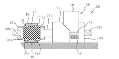
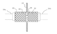
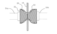
- FIGS. 1A and 1B A joining method for caulking and joining the first member 10 and the second member 20 using the caulking joining apparatus 30 will be described with reference to FIGS. 1A and 1B.
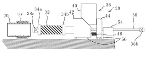
- the first member 10 and the second member 20 are caulked and joined using a rubber (elastic body) 32, a pair of pushers 34a and 34b, and a drive mechanism 36.
- the first member 10 is a hollow pipe type and is arranged to extend in the horizontal direction.
- the second member 20 is of a closed cross-sectional type, and includes end walls 14 and 14 provided with two holes 12 and 12 penetrating in the horizontal direction, and two side walls 16 connecting the two end walls 14 and 14. , 16.
- the rubber 32 is a hollow pipe shape extending in the horizontal direction, and a through hole 32a (see FIG. 4) through which the guide shaft 38 is inserted is provided at the center.
- the rubber 32 is supported by the guide shaft 38 when the guide shaft 38 is inserted into the through hole 32a (see FIG. 4), and the posture and position are maintained.
- the material of the rubber 32 is preferably, for example, any of urethane rubber, chloroprene rubber, CNR rubber (chloroprene rubber + nitrile rubber), or silicon rubber.
- the hardness of these rubbers 32 is preferably 30 or more on Shore A.
- the pair of pushers 34a and 34b are arranged on both sides of the rubber 32 and have a substantially cylindrical shape extending in the horizontal direction, and compress the rubber 32 by pressing it from both sides.
- the pressing surfaces 34c and 34d of the pushers 34a and 34b are formed flat, and when the rubber 32 is compressed, an even load is applied to the rubber 32.
- one pusher 34 a is fixed so as not to move with respect to the guide shaft 38.
- the other pusher 34b has an insertion hole (not shown) through which the guide shaft 38 is inserted. By inserting the guide shaft 38 through an insertion hole (not shown), the pusher 34 b is movable along the guide shaft 38.
- the other pusher 34 b is attached to the drive mechanism 36 and is moved in the horizontal direction along the guide shaft 38 by the drive mechanism 36.
- the drive mechanism 36 includes a cam driver 40 and a cam slider 42.
- the cam slider 42 has an insertion hole (not shown) through which the guide shaft 38 is inserted, and is movable along the guide shaft 38 in a state where the guide shaft 38 is inserted through the insertion hole.
- the pusher 34b is attached to the cam slider 42 so that the insertion hole of the cam slider 42 and the insertion hole of the pusher 34b are concentric. Accordingly, the pusher 34b can move along the guide shaft 38 together with the cam slider 42 in a state where the guide shaft 38 is inserted through the insertion hole of the cam slider 42 and the insertion hole of the pusher 34b.
- the cam slider 42 has an inclined surface 42a for transmitting a force from the cam driver 40 at an upper portion thereof.
- the cam driver 40 is movable in the vertical direction, and has an inclined surface 40 a for transmitting force to the cam slider 42 at its lower part.
- the drive mechanism 36 of the present embodiment has a cam mechanism that includes the cam slider 42 and the cam driver 40.
- a press machine or the like often used for press working or the like may be used.
- a standing wall portion 44 that stops the drive mechanism 36 from moving outward in the horizontal direction is provided outside the drive mechanism 36 in the horizontal direction (right side in the drawing).
- the standing wall portion 44 is provided with an insertion hole (not shown) through which the guide shaft 38 is inserted.
- the guide shaft 38 extends outward in the horizontal direction of the standing wall portion 44 through the insertion hole. Therefore, one end 38 a of the guide shaft 38 is fixed to the guide shaft 38 together with the one pusher 34 a, and the other end 38 b is fixed to the guide shaft 38 outside the standing wall portion 44 in the horizontal direction.
- the standing wall portion 44 and the cam slider 42 are elastically connected by a coil spring (biasing portion) 46, and the cam slider 42 is biased toward the standing wall portion 44.
- the caulking joining of the first member 10 and the second member 20 is performed according to the following procedure.
- the second member 20 is inserted into the hole 12 of the first member 10, and the guide shaft 38 is inserted into the through hole 32 a of the rubber 32. Then, the rubber 32 having the guide shaft 38 inserted therein is inserted into the second member 20, the pushers 34 a and 34 b are disposed on both sides of the rubber 32, and both ends 38 a and 38 b of the guide shaft 38 are fixed. At this time, one pusher 34 a is fixed so as not to move with respect to the guide shaft 38, and the other pusher 34 b is arranged to be movable along the guide shaft 38 by the drive mechanism 36.
- FIG. 1A shows the state at this time.
- FIG. 1B shows the state at this time.
- the cam driver 40 of the drive mechanism 36 is moved upward to unload the horizontal force (leftward in the figure) applied to the cam slider 42,
- the cam slider 42 is returned to the original position by the coil spring 46.
- the rubber 32 that has been expanded in the second member 20 is unloaded, returns from the radially expanded state to the natural state, and the contact with the second member 20 is released. Therefore, the first member 10 and the second member 20 that are caulked and joined can be easily detached from the caulking and joining device 30 without receiving a frictional force from the rubber 32.
- Electromagnetic forming can be used only for conductive materials, and the cross-sectional shape and dimensions are limited by the coil used. In contrast, this method does not depend on the material, and there are no restrictions on the cross-sectional shape and dimensions.
- the two members 10 and 20 can be joined at a low cost.
- the rubber 32 is supported in the horizontal direction by the guide shaft 38 and the pushers 34a and 34b are moved in the horizontal direction (in the direction of the guide shaft 38) to compress and rubber-bond the rubber 32, the second member 20 is placed horizontally. Can be placed. Therefore, it can be caulked and joined to the long second member 20.
- the horizontal direction in which the guide shaft 38 extends includes an inclination direction in addition to a strict horizontal direction.
- the second member 20 can be arranged in the horizontal direction by using the cam mechanism of the drive mechanism 36 while using a facility for applying a compressive force in the vertical direction that is often used in a normal press machine or the like. Caulking can be performed without restriction of shape. In particular, when the second member 20 is long, it is impossible to caulk and join with the equipment that applies a normal compressive force due to size limitations, but in this configuration, caulking can be performed even when the second member 20 is long. It is.
- cam slider 42 and the pusher 34b are automatically returned to the original positions by the coil spring 46, it is not necessary to manually return the cam slider 42 and the pusher 34b to the original positions, and workability can be improved.
- the drive mechanism 36 only needs to be provided for the other pusher 34b, and the configuration of the drive mechanism 36 can be simplified. Furthermore, the movement of the first member 10 and the second member 20 can be restricted, and workability can be improved.
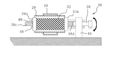
- FIG. 2A and 2B show a guide shaft rotating type caulking joining device 30.
- the drive mechanism 36 of the caulking and joining device 30 does not include the cam slider 42 and the cam driver 40 as described above.
- the pushers 34 a and 34 b are moved relatively close to each other in the horizontal direction to compress the rubber 32.
- screw grooves 38 c and 38 d are formed on the guide shaft 38, and the two support bars 48 and 48 pass through the pushers 34 a and 34 b and the rubber 32. For this reason, the pushers 34a and 34b and the rubber 32 have insertion holes (not shown) corresponding to the support rods 48 and 48 that pass therethrough.
- the caulking and joining device 30 moves the pushers 34a and 34b close to each other by the rotational torque applied to the guide shaft 38, compresses the rubber 32 in the horizontal direction, and expands it in the radial direction.
- the member 10 and the second member 20 are caulked and joined.
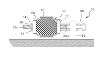
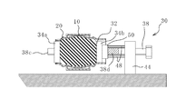
- FIG. 3A and 3B show another guide shaft rotating type caulking joining device 30.
- FIG. 2A and 2B has screw grooves 38c and 38d (FIGS. 2A and 2B) formed so that the pushers 34a and 34b on both sides move close to each other, but FIGS. 3A and 3B.
- one pusher 34 a is fixed to the guide shaft 38.
- the other pusher 34 b is formed with a thread groove 38 d only on one side with respect to the joint so as to move in the horizontal direction along the guide shaft 38.
- a pusher 50 that moves in the horizontal direction with the rotation of the guide shaft 38 and presses and moves the other pusher 34b in the horizontal direction. It has been. Support rods 48 are passed through the pusher 50. When the guide shaft 38 is rotated, rotational torque is transmitted to the pusher 50 through the screw groove 38d. However, since the rotation of the pusher 50 is stopped by the support bars 48, 48, the pusher 50 moves along the screw groove 38d of the guide shaft 38 without rotating. Therefore, the other pusher 34 b is pushed by the pusher 50 and moves along the guide shaft 38, and approaches the one pusher 34 a fixed to the guide shaft 38.
- FIG. 4 to 5B show a caulking joining device 30 in which the second member 20 has a partition wall 22 and a plurality of guide shafts 38 are provided.
- the modes of the rubber 32 and the second member 20 can be variously changed.
- the second member 20 has a square outer shape and includes a partition wall 22 that divides the inside into four. Also good. In this case, four rubbers 32 and four guide shafts 38 to be inserted are required.
- the strength of the second member 20 can be improved by providing the partition wall 22 in this way.
- the cross-sectional shape is not limited to a quadrangle, and may be an arbitrary shape. Further, the shape of the partition wall 22 is not particularly limited, and for example, the second member 20 may be divided into two.
- FIGS. 5A and 5B there are a plurality of guide shafts 38, 38 and pushers 34a, 34b, but the other configuration is the same as the configuration of the present embodiment. Thus, even when the second member 20 has the partition wall 22, the present invention is applicable.
- the modes of the first member 10 and the second member 20 can be variously changed.
- the cross-sectional shapes of the hole 12 of the first member 10 and the second member 20 should be similar (for example, both circular). Since the cross-sectional shapes of the hole portion 12 and the second member 20 of the first member 10 are similar to each other, the second member 20 can be uniformly enlarged and deformed and joined to the first member 10 and the second member 20. And local load can be prevented.
- the present invention is applicable even if the hole 12 of the first member 10 and the cross-sectional shape of the second member 20 are not similar (for example, a circle and a quadrangle).
- the joining position of the first member 10 and the second member 20 may be two or more.
- the first member 10 may be a hat type as shown in FIGS. 7A and 7B or may have other shapes.
- the hole 12 of the first member 10 is preferably subjected to burring.
- the strength of the hole 12 of the first member 10 can be improved, so that the deformation of the first member 10 is prevented, and the first member 10 is deformed. This is because the damage of the two members 20 can be prevented, and the joining strength can be improved by increasing the joining area by burring.
- the first member 10 and the second member 20 may be caulked and joined using an outer frame mold 52.
- the outer frame mold 52 may have a cylindrical shape concentric with the second member 20.
- the outer frame mold 52 is disposed on the radially outer side of the second member 20.
- a gap is provided between the second member 20 and the outer frame mold 52.
- the rubber 32 is expanded radially outward by the pushers 34a and 34b, so that when the second member 20 is enlarged and deformed, the inner shape of the outer frame mold 52 is adapted. be able to.
- the rubber 32 may be separated in the vicinity of the hole 12. Since the rubber 32 is separated at the hole 12, that is, the joint, the deformation of the hole 12 of the first member 10 can be prevented. Specifically, since the rubber 32 is separated, an expansion deformation force is not applied to the hole portion 12, and the original shape of the hole portion 12 can be maintained.
- FIGS. 11A to 11E The caulking joining method of this embodiment shown in FIGS. 11A to 11E is the same as that of the first embodiment of FIGS. 1A and 1B except for the portion related to the pusher (guide shaft moving mechanism) 54. Therefore, the same parts as those shown in FIGS. 1A and 1B may be denoted by the same reference numerals and description thereof may be omitted.
- FIG. 11A to FIG. 11E are diagrams showing the first to fifth steps of the present embodiment.
- wheels 56 are provided at the lower ends of the cam slider 42 and the standing wall portion 44, and the cam slider 42 and the standing wall portion 44 are movable in the horizontal direction.
- the cam driver 40 can also be moved in the horizontal direction by a rail mechanism or the like (not shown).
- a pusher 54 is provided on the outer side in the horizontal direction of the standing wall portion 44.
- the pusher 54 supports the guide shaft 38 and moves the guide shaft 38 in the horizontal direction.
- the method by which the pusher 54 moves the guide shaft 38 is not particularly limited.
- the guide shaft 38 may be sent out or pulled in using a motor, a gear, or the like.
- the standing wall 44 is fixed to the guide shaft 38 and is moved together with the guide shaft 38 by the pusher 54. Accordingly, as the guide shaft 38 moves, the upright wall portion 44, the drive mechanism 36, and the pair of pushers 34a and 34b are moved together without changing their relative positions in the horizontal direction.
- the second step of FIG. 11B is a state where the rubber 32 is inserted into the second member 20 by the pusher 54.
- a compression force is applied to the rubber 32 in the direction of the guide shaft 38 by the drive mechanism 36, the rubber 32 is expanded radially outward, and the first member 10 and the second member 20 are caulked and joined.
- the fourth step in FIG. 11D is a state in which the compression force in the direction of the guide shaft 38 applied by the drive mechanism 36 is unloaded and the rubber 32 returns to the natural state.
- the fifth step of FIG. 11E is a state in which the caulking joining device 30 is moved by the pusher 54 and the rubber 32 is pulled out from the second member 20.
- the guide shaft 38 and the rubber 32 can be reliably inserted into the second member 20 by moving the guide shaft 38 in the horizontal direction by the pusher 54.
- FIG. 12A and 12B In the joining method of the present embodiment shown in FIGS. 12A and 12B, the structure other than the part relating to the structure in which the pushers 34a and 34b on both sides move together to compress the rubber 32 in the horizontal direction is shown in FIG. This is similar to the first embodiment of FIG. 1B. Therefore, the same parts as those shown in FIGS. 1A and 1B may be denoted by the same reference numerals and description thereof may be omitted.
- two drive mechanisms 36 and 36 and two standing wall portions 44 and 44 are provided, and the pair of pushers 34 a and 34 b are both attached to the cam slider 42 and fixed to the guide shaft 38. It has not been. Accordingly, the pushers 34a and 34b are both moved close to each other in the horizontal direction by the drive mechanisms 36 and 36, and the rubber 32 is compressed in the direction of the guide shaft 38.
- 34b there is a one-side access type in which the pusher 34b on one side moves relative to the rubber 32 as in the first and second embodiments, or the pushers 34a on both sides of the rubber 32 as in the third embodiment.
- 34b may be a double-sided access type that moves as appropriate depending on the type and application of the caulking joint.
Landscapes
- Engineering & Computer Science (AREA)
- Mechanical Engineering (AREA)
- Mounting, Exchange, And Manufacturing Of Dies (AREA)
- Automatic Assembly (AREA)
Abstract
本発明の部材の接合方法は、第1部材(10)の穴部(12)に第2部材(20)を挿通し、ゴム(32)の貫通孔(32a)にガイド軸(38)を挿通し、第2部材(20)の内部にガイド軸(38)が挿通されたゴム(32)を挿入し、駆動機構(36)により押子(34a,34b)を相対的に近接移動させてゴム(32)をガイド軸(38)方向に圧縮して内側から外側に向けて膨張させ、それによって第2部材(20)の少なくとも穴部(12)に挿通された部分を拡大変形させて第1部材(10)にかしめ接合する。これにより各部材に対する負荷を軽減し、接合強度を向上させ、形状や材料についての制限を受けることなく、特に長尺な第2部材(20)に対しても低コストで第1部材(10)を接合できる部材の接合方法を提供する。
Description
本発明は、部材の接合方法及び装置に関する。
自動車の軽量化や安全性向上のために、ハイテンション鋼と呼ばれる強度が高い薄鋼板が使用されている。これらのハイテンション鋼は軽量化や安全性向上に有効ではあるものの、アルミなどの低比重材料と比べると依然として重い。また、ハイテンション鋼には、その高強度ゆえに成形性が低下したり、成形荷重が上昇したり、更には寸法精度が低下するなどの問題がある。これらの問題を解決するために、近年、鋼板よりも比重が軽いアルミを用いた押し出し成形品や鋳造品、プレス成形品を鋼製部品と合わせて活用するマルチマテリアル化が行われている。
このマルチマテリアル化で問題となるのは鋼板製部品とアルミ部品の接合である。スポット溶接に代表される溶接技術においては鋼板とアルミ板の界面に脆弱な金属間化合物(IMC:intermetallic compound)が生じるため、電磁成形接合、ボルトとナットに代表されるねじ締結、摩擦撹拌接合(FSW:friction stir welding)、リベット、セルフピアスリベット(SPR:self-piercing rivet)、メカニカルクリンチング、接着などの接合技術が実用化されている。
電磁成形によるかしめは、相手部品に嵌合させたパイプ状の部品の内側にソレノイド成形コイルを挿入し、コイルに衝撃電流を流すことによって生ずる変化磁界により、導体のパイプに誘導電流を誘起させる。コイルの1次電流による磁界と、パイプの周方向上に反対方向に流れる誘導電流との間に電磁力が発生し、このときパイプは径方向外側に向かう力を受けるため変形拡大され相手部品にかしめ接合される。この接合方法は、電気伝導度の良い銅やアルミに適しており、自動車部品の接合においても一部で実用化されている。
特許文献1では、マルチマテリアル化のための電磁成形によるかしめ接合技術が開示されている。具体的には、断面が中空の金属形材からなるバンパーリインフォースを電磁成形により変形拡大し、アルミニウム合金製のバンパーステイに設けられた穴部と嵌合させて接合している。
特許文献1のように、電磁成形は、電気伝導度の良い銅やアルミの中空部品を相手部品にかしめ接合するのに適しており、また、その接合メカニズムより、円形形状が好ましい。
しかし、電磁成形による接合では、使用するソレノイドコイルはアルミ部品(アルミパイプ)の内径よりも小さいことが必要になる。小径部品を接合する場合にコイルを小径化しようとすると、コイルの製造の困難性や性能及び耐久性の点で問題がある。特に製造の困難性については、導線をコイル形状に成形することが困難になり、導線の材質及び断面形状に対する制限が厳しくなると共に、コイル形状に成形する際に、導線断面が変形する。また、大容量の高電圧のコンデンサが必要であると言った新たな設備投資が必要となる。更に、角型断面、穴、又はスリットが形成されているアルミ部品に対しては接合できない。
電磁成形以外のかしめ接合の場合でも、部材の形状について制限を受ける場合がある。例えば、長尺部材はプレス機のような接合装置に配置することができず、かしめ接合できない。
本発明は、各部材に対する負荷を軽減し、接合強度を向上させ、形状や材料についての制限を受けることなく、特に長尺な部材に対しても低コストで2つの部材を接合できる部材の接合方法を提供することを課題とする。
本発明の第1の態様は、穴部が設けられた第1部材と、中空状の第2部材と、貫通孔を有する弾性体と、前記弾性体の両側に配置され水平方向に延びるガイド軸を支持し前記ガイド軸方向に移動可能な一対の押子と、前記押子を前記ガイド軸方向に沿って相対的に近接移動させる駆動機構とを準備し、
前記第1部材の前記穴部に前記第2部材を挿通し、
前記弾性体の前記貫通孔に前記ガイド軸を挿通し、
前記第2部材の内部に前記ガイド軸が挿通された前記弾性体を挿入し、
前記駆動機構により前記押子を相対的に近接移動させて前記弾性体を前記ガイド軸方向に圧縮して内側から外側に向けて膨張させ、それによって前記第2部材の少なくとも前記穴部に挿通された部分を拡大変形させて前記第1部材にかしめ接合する、部材の接合方法を提供する。
前記第1部材の前記穴部に前記第2部材を挿通し、
前記弾性体の前記貫通孔に前記ガイド軸を挿通し、
前記第2部材の内部に前記ガイド軸が挿通された前記弾性体を挿入し、
前記駆動機構により前記押子を相対的に近接移動させて前記弾性体を前記ガイド軸方向に圧縮して内側から外側に向けて膨張させ、それによって前記第2部材の少なくとも前記穴部に挿通された部分を拡大変形させて前記第1部材にかしめ接合する、部材の接合方法を提供する。
この方法によれば、弾性体を径方向外側へ膨張させて第2部材を均等に拡大変形することで、局所的な変形を防止し、各部材に対する負荷を軽減できる。これはガイド軸方向に圧縮された弾性体が径方向内側から外側に向かって均等に膨張する性質を利用し、第2部材を均等に変形できるためである。従って、嵌合精度が向上し、接合強度を向上できる。また、電磁成形やその他の加工方法と比べて簡易である。電磁成形は導電材料にのみ使用可能であり、断面形状や寸法についても使用するコイルによって制約がある。これに対し、この方法は材質によらず、断面形状や寸法に関する制約もない。さらに大容量のコンデンサを要する電気的な設備も不要であり、低コストで2つの部材を接合できる。特に、弾性体をガイド軸によって水平方向に支持し、押子を水平方向(ガイド軸方向)に移動させて弾性体を圧縮してかしめ接合するため、第2部材を水平に配置できる。従って、長尺な第2部材に対してもかしめ接合できる。ここでガイド軸が延びる水平方向とは、厳密な水平方向以外に傾斜方向も含む。
前記駆動機構は、前記ガイド軸方向とは異なる方向に付加された力を前記ガイド軸方向の力に変換するカム機構をさらに備え、
前記カム機構により方向変換した力で前記弾性体を圧縮することが好ましい。
前記カム機構により方向変換した力で前記弾性体を圧縮することが好ましい。
カム機構により、通常の垂直方向に圧縮力を付加する設備を使用しつつ、水平方向に第2部材を配置できるため、第2部材について形状の制限を受けることなくかしめ接合できる。特に、第2部材が長尺な場合、通常の圧縮力を付加する設備では寸法の制限上かしめ接合不可能であったが、本構成では第2部材が長尺な場合もかしめ接合可能である。
前記駆動機構は、前記ガイド軸方向外側へ前記押子を付勢する付勢部を備え、
前記弾性体の前記ガイド軸方向への圧縮後、前記付勢部により前記押子が戻されることが好ましい。
前記弾性体の前記ガイド軸方向への圧縮後、前記付勢部により前記押子が戻されることが好ましい。
付勢部により、押子が自動的に元の位置に戻されるため、手動で押子を元の位置に戻す必要がなく、作業性を向上できる。
前記一対の押子のうち、一方は固定されていることが好ましい。
押子の一方を固定することで、駆動機構を片側の押子に対してのみ設ければよく、駆動機構の構成を簡略化できる。さらに、第1部材及び第2部材の動きを制限でき、作業性を向上できる。
前記ガイド軸を水平方向に移動させるガイド軸移動機構をさらに備え、
前記ガイド軸移動機構により前記第2部材の内部に前記ガイド軸に挿通された前記弾性体を挿入することが好ましい。
前記ガイド軸移動機構により前記第2部材の内部に前記ガイド軸に挿通された前記弾性体を挿入することが好ましい。
ガイド軸移動機構によりガイド軸を水平方向に移動させることで、ガイド軸及び弾性体を第2部材に確実に挿入できる。
本発明の第2の態様は、貫通孔を有する弾性体を使用して、穴部が設けられた第1部材と、中空状の第2部材とをかしめ接合する部材の接合装置であって、
前記弾性体の両側に配置された状態で水平方向に延びるガイド軸を支持しており、前記ガイド軸方向に移動可能な一対の押子と、
前記押子を前記ガイド軸方向に沿って相対的に近接移動させる駆動機構と
を備え、
前記第1部材の前記穴部に前記第2部材を挿通して前記第1部材を貫通させた状態で、かつ、前記弾性体の前記貫通孔に前記ガイド軸を挿通した状態で、かつ、前記第2部材の内部に前記ガイド軸に挿通された前記弾性体を挿入した状態で、前記駆動機構で前記押子が駆動されることにより前記弾性体が前記ガイド軸方向に圧縮されて内側から外側に向けて膨張され、それによって前記第2部材の少なくとも前記穴部に挿通された部分が拡大変形されて前記第1部材にかしめ接合する、部材の接合装置を提供する。
前記弾性体の両側に配置された状態で水平方向に延びるガイド軸を支持しており、前記ガイド軸方向に移動可能な一対の押子と、
前記押子を前記ガイド軸方向に沿って相対的に近接移動させる駆動機構と
を備え、
前記第1部材の前記穴部に前記第2部材を挿通して前記第1部材を貫通させた状態で、かつ、前記弾性体の前記貫通孔に前記ガイド軸を挿通した状態で、かつ、前記第2部材の内部に前記ガイド軸に挿通された前記弾性体を挿入した状態で、前記駆動機構で前記押子が駆動されることにより前記弾性体が前記ガイド軸方向に圧縮されて内側から外側に向けて膨張され、それによって前記第2部材の少なくとも前記穴部に挿通された部分が拡大変形されて前記第1部材にかしめ接合する、部材の接合装置を提供する。
本発明によれば、弾性体を内側から外側に向けて膨張させて第2部材を均等に変形拡大することで、局所的な変形を防止し、各部材に対する負荷を軽減できる。従って、嵌合精度が向上し、接合強度を向上できる。また、電磁成形やその他の加工方法と比べて簡易であり、形状や材料についての制限を受けることなく、低コストで2つの部材を接合できる。特に、第2部材を水平に配置できるため、長尺な部材であっても接合可能である。
以下、添付図面を参照して本発明の実施形態を説明する。以下で説明する各実施形態では第1部材10及び第2部材20の材料は特に限定されず、本発明は任意の材料に対して適用できる。
(第1実施形態)
図1A及び図1Bを参照して、かしめ接合装置30を使用して第1部材10と第2部材20をかしめ接合する接合方法について説明する。本実施形態のかしめ接合装置30では、ゴム(弾性体)32と、一対の押子34a,34bと、駆動機構36とを使用して、第1部材10と第2部材20をかしめ接合する。
図1A及び図1Bを参照して、かしめ接合装置30を使用して第1部材10と第2部材20をかしめ接合する接合方法について説明する。本実施形態のかしめ接合装置30では、ゴム(弾性体)32と、一対の押子34a,34bと、駆動機構36とを使用して、第1部材10と第2部材20をかしめ接合する。
第1部材10は、中空状のパイプ型であり、水平方向に延びるように配置されている。
第2部材20は、閉断面型であり、水平方向に貫通している2つの穴部12,12が設けられた端壁14,14と、2つの端壁14,14を繋ぐ2つの側壁16,16とを備える。
ゴム32は、水平方向に延びる中空状のパイプ型であり、中心にはガイド軸38を挿通するための貫通孔32a(図4参照)が設けられている。ゴム32は、貫通孔32a(図4参照)にガイド軸38が挿通されることにより、ガイド軸38により支持され、姿勢及び位置を維持される。ゴム32の材質は、例えば、ウレタンゴム、クロロプレンゴム、CNRゴム(クロロプレンゴム+ニトリルゴム)、又はシリコンゴムのいずれかを用いることが好ましい。また、これらのゴム32の硬度はショアAで30以上であることが好ましい。
一対の押子34a,34bは、ゴム32の両側に配置され、水平方向に延びる概略円柱状であり、ゴム32を両側から押圧して圧縮する。押子34a,34bの押圧面34c,34dは平坦に形成されており、ゴム32が圧縮される際にはゴム32に対して均等に負荷がかかる。本実施形態では、一方の押子34aはガイド軸38に対して移動しないように固定されている。他方の押子34bはガイド軸38が挿通する図示しない挿通孔を有している。図示しない挿通孔にガイド軸38が挿通されることで、押子34bはガイド軸38に沿って移動可能である。また、他方の押子34bは、駆動機構36に取り付けられており、駆動機構36によりガイド軸38に沿って水平方向に移動される。
駆動機構36は、カムドライバ40及びカムスライダ42を備える。カムスライダ42は、ガイド軸38が挿通される図示しない挿通孔を有し、ガイド軸38が挿通孔に挿通された状態でガイド軸38に沿って移動可能である。
カムスライダ42の挿通孔と押子34bの挿通孔は、同心となるように押子34bがカムスライダ42に取り付けられている。従ってガイド軸38がカムスライダ42の挿通孔と押子34bの挿通孔に挿通された状態で、押子34bはカムスライダ42と共にガイド軸38に沿って移動可能である。
また、カムスライダ42は、カムドライバ40から力を伝達されるための傾斜面42aをその上部に有する。カムドライバ40は、垂直方向に移動可能であり、カムスライダ42に力を伝達するための傾斜面40aをその下部に有する。カムドライバ40に下向きの力が付加されると、傾斜面40a,42aを介してカムドライバ40からカムスライダ42に力が伝達され、カムドライバ40が垂直方向(図において下方向)へ移動すると共にカムスライダ42はガイド軸38に沿って水平方向(図において左方向)へ移動する。即ち、本実施形態の駆動機構36は、カムスライダ42とカムドライバ40とから構成されるカム機構を有している。カムドライバ40には、例えば通常よくプレス加工などに使用されるプレス機械等を使用してもよい。
駆動機構36の水平方向外側(図において右側)には、駆動機構36の水平方向外側への移動を止める立壁部44が設けられている。立壁部44にはガイド軸38が挿通される図示しない挿通孔が設けられており、ガイド軸38はこの挿通孔を通じて立壁部44の水平方向外側へ延びている。従って、ガイド軸38は、一端38aが一方の押子34aと共にガイド軸38に対して固定され、他端38bが立壁部44の水平方向外側でガイド軸38に対して固定されている。
立壁部44及びカムスライダ42はコイルばね(付勢部)46により弾性的に接続され、カムスライダ42は立壁部44へ向かって付勢されている。
第1部材10と第2部材20のかしめ接合は、以下の手順で実行される。
まず、第1部材10の穴部12に第2部材20を挿通し、ゴム32の貫通孔32aにガイド軸38を挿通する。そして、第2部材20の内部にガイド軸38が挿通されたゴム32を挿入してゴム32の両側に押子34a,34bを配置し、ガイド軸38の両端38a,38bを固定する。このとき、一方の押子34aはガイド軸38に対して移動しないように固定され、他方の押子34bは駆動機構36によりガイド軸38に沿って移動可能に配置されている。このときの状態を示すのが図1Aである。
次に、駆動機構36のカムドライバ40に対して下向きの力を付加し、カムドライバ40を下向きに移動させ、傾斜面40a,42aを介してカムドライバ40からカムスライダ42に力を伝達するともに垂直方向(図において下方向)の力を水平方向(図において左方向)の力へと変換する。そしてカムスライダ42をゴム32を圧縮するガイド軸38方向に移動させる。一方の押子34aはガイド軸38に対して固定されており、他方の押子34bはカムスライダ42と共にガイド軸38に沿って左方向に移動するため、押子34a,34bは相対的に近接移動し、ゴム32をガイド軸38方向に圧縮して径方向内側から外側に向けて膨張させる。このように第2部材20の少なくとも穴部12に挿通された部分を拡大変形させて第1部材10にかしめ接合する。このときの状態を示すのが図1Bである。
なお、図示していないが、かしめ接合後は、駆動機構36のカムドライバ40を上向きに移動させることで、カムスライダ42に付加されていた水平方向(図において左方向)の力が除荷され、コイルばね46によりカムスライダ42は元の位置に戻される。第2部材20内で膨張していたゴム32は、力が除荷され、径方向に膨張していた状態から自然状態に戻り、第2部材20に対する接触が解かれる。従って、かしめ接合された第1部材10と第2部材20は、ゴム32から摩擦力を受けることなく、かしめ接合装置30から簡単に取り外すことができる。
このように、ゴム32を径方向外側へ膨張させて第2部材20を均等に拡大変形することで、局所的な変形を防止し、各部材10,20に対する負荷を軽減できる。これはガイド軸38方向に圧縮されたゴム32が径方向内側から外側に向かって均等に膨張する性質を利用し、第2部材20を均等に変形できるためである。従って、嵌合精度が向上し、接合強度を向上できる。また、電磁成形やその他の加工方法と比べて簡易である。電磁成形は導電材料にのみ使用可能であり、断面形状や寸法についても使用するコイルによって制約がある。これに対し、この方法は材質によらず、断面形状や寸法に関する制約もない。さらに大容量のコンデンサを要する電気的な設備も不要であり、低コストで2つの部材10,20を接合できる。特に、ゴム32をガイド軸38によって水平方向に支持し、押子34a,34bを水平方向(ガイド軸38方向)に移動させてゴム32を圧縮してかしめ接合するため、第2部材20を水平に配置できる。従って、長尺な第2部材20に対してもかしめ接合できる。ここでガイド軸38が延びる水平方向とは、厳密な水平方向以外に傾斜方向も含む。
また、駆動機構36のカム機構により、通常プレス機械等でよく使用される垂直方向に圧縮力を付加する設備を使用しつつ、水平方向に第2部材20を配置できるため、第2部材20について形状の制限を受けることなくかしめ接合できる。特に、第2部材20が長尺な場合、通常の圧縮力を付加する設備では寸法の制限上かしめ接合不可能であったが、本構成では第2部材20が長尺な場合もかしめ接合可能である。
また、コイルばね46により、カムスライダ42及び押子34bが自動的に元の位置に戻されるため、手動でカムスライダ42及び押子34bを元の位置に戻す必要がなく、作業性を向上できる。
また、一方の押子34aをガイド軸38に対して固定することで、駆動機構36は他方の押子34bに対してのみ設けられればよく、駆動機構36の構成を簡略化できる。さらに、第1部材10及び第2部材20の動きを制限でき、作業性を向上できる。
図2A及び図2Bはガイド軸回転型のかしめ接合装置30を示している。このかしめ接合装置30の駆動機構36は、上記のようにカムスライダ42及びカムドライバ40を備えていない。このかしめ接合装置30は、ガイド軸38に対して回転トルクを付加することにより、押子34a,34bが連動して水平方向に相対的に近接移動してゴム32を圧縮する。
このかしめ接合装置30では、ガイド軸38に対してねじ溝38c,38dが形成されると共に、2つの支持棒48,48が押子34a,34bとゴム32とを貫通している。このため、押子34a,34b及びゴム32は、貫通する支持棒48,48に対応する図示しない挿通孔をそれぞれ有している。
ガイド軸38が図の矢印のように回転されると、ねじ溝38c,38dを介して押子34a,34bに回転トルクが伝達される。しかし、押子34a,34bは、支持棒48,48によって回転を止められているため、回転せずにガイド軸38のねじ溝38c,38dに沿って移動する。ねじ溝38c,38dは、同じ形状ではなく、押子34a,34bを互いに近接移動させるように、それぞれの押子34a,34bに対して別の形状に形成されている。
このように、このかしめ接合装置30は、ガイド軸38に対して与えた回転トルクにより押子34a,34bを互いに近接移動させ、ゴム32を水平方向に圧縮して径方向に膨張させ、第1部材10と第2部材20をかしめ接合する。
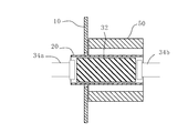
図3A及び図3Bは他のガイド軸回転型のかしめ接合装置30を示している。図2A及び図2Bのかしめ接合装置30は、両側の押子34a,34bが互いに近接移動するようにねじ溝38c,38d(図2A及び図2B)が形成されていたが、図3A及び図3Bのかしめ接合装置30は、一方の押子34aがガイド軸38に対して固定されている。他方の押子34bは、ガイド軸38に沿って水平方向に移動するように接合部に対して片側のみにねじ溝38dが形成されている。また、押子34bの水平方向外側(図において右側)には、ガイド軸38の回転に伴って水平方向に移動して他方の押子34bを水平方向に押圧して移動させる押し具50が設けられている。押し具50には支持棒48,48が貫通されている。ガイド軸38が回転されると、ねじ溝38dを介して押し具50に回転トルクが伝達される。しかし、押し具50は、支持棒48,48によって回転を止められているため、回転せずにガイド軸38のねじ溝38dに沿って移動する。従って、他方の押子34bは押し具50に押圧されてガイド軸38に沿って移動し、ガイド軸38に対して固定されている一方の押子34aに近づく。
このように、このかしめ接合装置30は、ガイド軸38が回転されることにより、他方の押子34bが一方の押子34aに近づき、ゴム32を水平方向に圧縮して径方向に膨張させ、第1部材10と第2部材20をかしめ接合する。
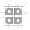
図4から図5Bは第2部材20が仕切壁22を有し、ガイド軸38が複数設けられたかしめ接合装置30を示している。ゴム32と第2部材20の態様は様々に変更可能であり、図4に示すように、第2部材20は、外形が四角型であり、内部を4分割する仕切壁22を有していてもよい。この場合、挿入されるゴム32及びガイド軸38もそれぞれ4つずつ必要である。
このように仕切壁22を設けることで第2部材20の強度を向上させることができる。また、断面形状は四角形に限定されず、任意の形状であってよい。さらに仕切壁22の形状も特に限定されず、例えば第2部材20を2分割する形状としてもよい。
図5A及び図5Bに示すように、ガイド軸38,38と押子34a,34bの数が複数存在しているが、それ以外の構成は本実施形態の構成と同様である。このように、第2部材20が仕切壁22を有している場合でも本発明は適用可能である。
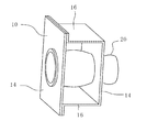
図6A及び図6Bに示すように、第1部材10と第2部材20の態様も様々に変更可能である。好ましくは図6Aに示すように、第1部材10の穴部12と、第2部材20の断面形状は相似形(例えば共に円形)である方がよい。第1部材10の穴部12及び第2部材20の断面形状が互いに相似形であることで、第2部材20を均等に拡大変形して接合でき、第1部材10及び第2部材20に対して局所的な負荷が発生することを防止できる。ただし、図6Bに示すように、第1部材10の穴部12と、第2部材20の断面形状は相似形でなくても(例えば、円形と四角形)本発明は適用可能である。
図7A及び図7Bに示すように、第1部材10と第2部材20の接合箇所は2箇所以上でもよい。2箇所接合の場合、第1部材10は、図7A及び図7Bのようにハット型であってもよいし、その他の形状であってもよい。好ましくは、図8A及び図8Bに示すように、第1部材10の穴部12はバーリング加工が施されている方がよい。第1部材10の穴部12の縁をバーリング加工することで、第1部材10の穴部12の強度を向上できるため第1部材10の変形を防止し、第1部材10の変形に伴う第2部材20の損傷を防止でき、さらにバーリング加工により接合面積が増大することで接合強度を向上できるためである。
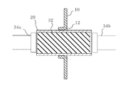
また、図9A及び図9Bに示すように、外枠金型52を使用して第1部材10と第2部材20をかしめ接合してもよい。外枠金型52は、第2部材20と同心の円筒状であってもよい。外枠金型52は、第2部材20の径方向外側に配置されている。図9Aのようにゴム32を水平方向に圧縮して径方向外側へ膨張させる前の状態では、第2部材20と外枠金型52の間には隙間が設けられている。この状態から、図9Bに示すように、押子34a,34bによりゴム32を径方向外側へ膨張させることで、第2部材20が拡大変形した際に外枠金型52の内面形状になじませることができる。
また、図10A及び図10Bに示すように、ゴム32は穴部12の付近で分離されていてもよい。ゴム32が穴部12、即ち接合部で分離されていることで、第1部材10の穴部12の変形を防止できる。具体的には、ゴム32が分離されているため、穴部12に対しては拡大変形力が付加されず、穴部12の元の形状を維持できる。
(第2実施形態)
図11Aから図11Eに示す本実施形態のかしめ接合方法は、プッシャー(ガイド軸移動機構)54に関する部分以外の構成は図1A及び図1Bの第1実施形態と同様である。従って、図1A及び図1Bに示した構成と同様の部分については同様の符号を付して説明を省略する場合がある。
図11Aから図11Eに示す本実施形態のかしめ接合方法は、プッシャー(ガイド軸移動機構)54に関する部分以外の構成は図1A及び図1Bの第1実施形態と同様である。従って、図1A及び図1Bに示した構成と同様の部分については同様の符号を付して説明を省略する場合がある。
図11Aから図11Eは、本実施形態の第1工程から第5工程までを示す図である。本実施形態では、カムスライダ42及び立壁部44の下端に車輪56が設けられており、カムスライダ42及び立壁部44が水平方向に移動可能である。また、カムドライバ40も図示しないレール機構等により水平方向に移動可能である。
立壁部44の水平方向外側には、プッシャー54が設けられている。プッシャー54は、ガイド軸38を支持し、ガイド軸38を水平方向に移動させる。プッシャー54がガイド軸38を移動させる方法は特に限定されず、例えばモータやギア等を使用してガイド軸38を送り出すか又は引き入れるようにしてもよい。
立壁部44は、ガイド軸38に対して固定されており、プッシャー54によりガイド軸38と共に移動される。従って、ガイド軸38の移動に伴い、立壁部44と駆動機構36と一対の押子34a,34bとは、水平方向に相対的な位置を変えることなく、合わせて移動される。
図11Aの第1工程は、第1部材10の穴部12に第2部材20が挿通された状態である。図11Bの第2工程は、プッシャー54により第2部材20内にゴム32が挿入された状態である。図11Cの第3工程は、駆動機構36によりゴム32にガイド軸38方向に圧縮力が付加され、ゴム32が径方向外側へ膨張され、第1部材10と第2部材20がかしめ接合された状態である。図11Dの第4工程は、駆動機構36により付与されたガイド軸38方向の圧縮力が除荷され、ゴム32が自然状態に戻った状態である。図11Eの第5工程は、プッシャー54によりかしめ接合装置30が移動され、第2部材20からゴム32が引き抜かれた状態である。
このように、プッシャー54によりガイド軸38を水平方向に移動させることで、ガイド軸38及びゴム32を第2部材20に確実に挿入できる。
(第3実施形態)
図12A及び図12Bに示す本実施形態の接合方法は、両側の押子34a,34bが共に移動してゴム32を水平方向に圧縮する構成となっていることに関する部分以外の構成は図1A及び図1Bの第1実施形態と同様である。従って、図1A及び図1Bに示した構成と同様の部分については同様の符号を付して説明を省略する場合がある。
図12A及び図12Bに示す本実施形態の接合方法は、両側の押子34a,34bが共に移動してゴム32を水平方向に圧縮する構成となっていることに関する部分以外の構成は図1A及び図1Bの第1実施形態と同様である。従って、図1A及び図1Bに示した構成と同様の部分については同様の符号を付して説明を省略する場合がある。
本実施形態では、駆動機構36,36及び立壁部44,44が2つずつ設けられており、一対の押子34a,34bは、共にカムスライダ42に取り付けられており、ガイド軸38に対して固定されていない。従って、押子34a,34bが共に駆動機構36,36により水平方向に互いに近接移動し、ガイド軸38方向にゴム32を圧縮する。
このように、第1及び第2実施形態のようにゴム32に対して片側の押子34bが移動する片側アクセス型あるか、第3実施形態のようにゴム32に対して両側の押子34a,34bが移動する両側アクセス型であるかは、かしめ接合の態様や用途に応じて適宜使い分ければよい。
10 第1部材
12 穴部
14 端壁
16 側壁
20 第2部材
22 仕切壁
30 かしめ接合装置
32 ゴム
32a 貫通孔
34a,34b 押子
34c,34d 押圧面
36 駆動機構
38 ガイド軸
38a 一端
38b 他端
38c,38d ねじ溝
40 カムドライバ
40a 傾斜面
42 カムスライダ
42a 傾斜面
44 立壁部
46 コイルばね(付勢部)
48 支持棒
50 押し具
52 外枠金型
54 プッシャー(ガイド軸移動機構)
56 車輪
12 穴部
14 端壁
16 側壁
20 第2部材
22 仕切壁
30 かしめ接合装置
32 ゴム
32a 貫通孔
34a,34b 押子
34c,34d 押圧面
36 駆動機構
38 ガイド軸
38a 一端
38b 他端
38c,38d ねじ溝
40 カムドライバ
40a 傾斜面
42 カムスライダ
42a 傾斜面
44 立壁部
46 コイルばね(付勢部)
48 支持棒
50 押し具
52 外枠金型
54 プッシャー(ガイド軸移動機構)
56 車輪
Claims (6)
- 穴部が設けられた第1部材と、中空状の第2部材と、貫通孔を有する弾性体と、前記弾性体の両側に配置され水平方向に延びるガイド軸を支持し前記ガイド軸方向に移動可能な一対の押子と、前記押子を前記ガイド軸方向に沿って相対的に近接移動させる駆動機構とを準備し、
前記第1部材の前記穴部に前記第2部材を挿通し、
前記弾性体の前記貫通孔に前記ガイド軸を挿通し、
前記第2部材の内部に前記ガイド軸が挿通された前記弾性体を挿入し、
前記駆動機構により前記押子を相対的に近接移動させて前記弾性体を前記ガイド軸方向に圧縮して内側から外側に向けて膨張させ、それによって前記第2部材の少なくとも前記穴部に挿通された部分を拡大変形させて前記第1部材にかしめ接合する、部材の接合方法。 - 前記駆動機構は、前記ガイド軸方向とは異なる方向に付加された力を前記ガイド軸方向の力に変換するカム機構をさらに備え、
前記カム機構により方向変換した力で前記弾性体を圧縮する、請求項1に記載の部材の接合方法。 - 前記駆動機構は、前記ガイド軸方向外側へ前記押子を付勢する付勢部を備え、
前記弾性体の前記ガイド軸方向への圧縮後、前記付勢部により前記押子が戻される、請求項1又は請求項2に記載の部材の接合方法。 - 前記一対の押子のうち、一方は固定されている、請求項1または請求項2に記載の部材の接合方法。
- 前記ガイド軸を水平方向に移動させるガイド軸移動機構をさらに備え、
前記ガイド軸移動機構により前記第2部材の内部に前記ガイド軸に挿通された前記弾性体を挿入する、請求項1または請求項2に記載の部材の接合方法。 - 貫通孔を有する弾性体を使用して、穴部が設けられた第1部材と、中空状の第2部材とをかしめ接合する部材の接合装置であって、
前記弾性体の両側に配置された状態で水平方向に延びるガイド軸を支持しており、前記ガイド軸方向に移動可能な一対の押子と、
前記押子を前記ガイド軸方向に沿って相対的に近接移動させる駆動機構と
を備え、
前記第1部材の前記穴部に前記第2部材を挿通して前記第1部材を貫通させた状態で、かつ、前記弾性体の前記貫通孔に前記ガイド軸を挿通した状態で、かつ、前記第2部材の内部に前記ガイド軸に挿通された前記弾性体を挿入した状態で、前記駆動機構で前記押子が駆動されることにより前記弾性体が前記ガイド軸方向に圧縮されて内側から外側に向けて膨張され、それによって前記第2部材の少なくとも前記穴部に挿通された部分が拡大変形されて前記第1部材にかしめ接合する、部材の接合装置。
Priority Applications (1)
| Application Number | Priority Date | Filing Date | Title |
|---|---|---|---|
| US15/763,418 US20180272478A1 (en) | 2015-09-28 | 2016-08-22 | Method and device for joining members |
Applications Claiming Priority (2)
| Application Number | Priority Date | Filing Date | Title |
|---|---|---|---|
| JP2015-190159 | 2015-09-28 | ||
| JP2015190159A JP6653150B2 (ja) | 2015-09-28 | 2015-09-28 | 部材の接合方法及び装置 |
Publications (1)
| Publication Number | Publication Date |
|---|---|
| WO2017056782A1 true WO2017056782A1 (ja) | 2017-04-06 |
Family
ID=58423456
Family Applications (1)
| Application Number | Title | Priority Date | Filing Date |
|---|---|---|---|
| PCT/JP2016/074347 Ceased WO2017056782A1 (ja) | 2015-09-28 | 2016-08-22 | 部材の接合方法及び装置 |
Country Status (3)
| Country | Link |
|---|---|
| US (1) | US20180272478A1 (ja) |
| JP (1) | JP6653150B2 (ja) |
| WO (1) | WO2017056782A1 (ja) |
Cited By (1)
| Publication number | Priority date | Publication date | Assignee | Title |
|---|---|---|---|---|
| EP3738689A4 (en) * | 2018-01-11 | 2021-10-20 | Kabushiki Kaisha Kobe Seiko Sho (Kobe Steel, Ltd.) | CONNECTED BODY AND METHOD OF MANUFACTURING THIS CONNECTED BODY |
Families Citing this family (8)
| Publication number | Priority date | Publication date | Assignee | Title |
|---|---|---|---|---|
| JP6454233B2 (ja) * | 2015-02-06 | 2019-01-16 | 株式会社神戸製鋼所 | 部材の接合方法 |
| JP6573517B2 (ja) * | 2015-09-28 | 2019-09-11 | 株式会社神戸製鋼所 | バンパー部材の接合方法及びバンパー構造体 |
| JP7118645B2 (ja) * | 2017-06-27 | 2022-08-16 | 株式会社神戸製鋼所 | 部材の接合方法および接合体 |
| WO2019003764A1 (ja) * | 2017-06-27 | 2019-01-03 | 株式会社神戸製鋼所 | 部材の接合方法および接合体 |
| JP6990487B2 (ja) * | 2017-07-28 | 2022-01-12 | 三桜工業株式会社 | パイプ端部加工装置 |
| JP7152368B2 (ja) * | 2019-08-08 | 2022-10-12 | 株式会社神戸製鋼所 | 接合体及びその製造方法 |
| CN113118309B (zh) * | 2021-04-13 | 2022-07-01 | 陕西科技大学 | 一种超薄板材摩擦辅助铆接的方法及装置 |
| CN119525972B (zh) * | 2025-01-13 | 2025-09-26 | 广东品嘉灵智能科技有限公司 | 一种压装机 |
Citations (3)
| Publication number | Priority date | Publication date | Assignee | Title |
|---|---|---|---|---|
| JPS51133170A (en) * | 1975-05-16 | 1976-11-18 | Nikkei Aluminium Sales | Method of connecting pipe body and wall surface body with through hole |
| JPS58184025A (ja) * | 1982-04-23 | 1983-10-27 | Hitachi Ltd | 自動調心型拡管装置 |
| JPS64137B2 (ja) * | 1984-06-04 | 1989-01-05 | Oo Enu Kogyo Kk |
Family Cites Families (7)
| Publication number | Priority date | Publication date | Assignee | Title |
|---|---|---|---|---|
| US3432916A (en) * | 1966-04-18 | 1969-03-18 | Up Right Inc | Method for making a joint for hardened aluminum tubing |
| US4418457A (en) * | 1982-01-21 | 1983-12-06 | Cities Service Company | Apparatus and process for expanding to join a tube into a tube sheet opening |
| JPS59197322A (ja) * | 1983-04-21 | 1984-11-08 | O N Kogyo Kk | 薄肉ステンレス鋼管の拡管装置 |
| JP2004237320A (ja) * | 2003-02-06 | 2004-08-26 | Sankyo Oilless Industry Inc | カムスライダの戻し機構 |
| WO2004096905A2 (en) * | 2003-04-24 | 2004-11-11 | Arizona Board Of Regents, Acting For And On Behalf Of Arizona State University | Adjustable compliant mechanism |
| KR101225865B1 (ko) * | 2007-03-14 | 2013-01-24 | 현대자동차주식회사 | 프레스 장치 |
| JP5355963B2 (ja) * | 2008-08-26 | 2013-11-27 | 昭和電工株式会社 | パイプと被接合部材との接合方法 |
-
2015
- 2015-09-28 JP JP2015190159A patent/JP6653150B2/ja active Active
-
2016
- 2016-08-22 US US15/763,418 patent/US20180272478A1/en not_active Abandoned
- 2016-08-22 WO PCT/JP2016/074347 patent/WO2017056782A1/ja not_active Ceased
Patent Citations (3)
| Publication number | Priority date | Publication date | Assignee | Title |
|---|---|---|---|---|
| JPS51133170A (en) * | 1975-05-16 | 1976-11-18 | Nikkei Aluminium Sales | Method of connecting pipe body and wall surface body with through hole |
| JPS58184025A (ja) * | 1982-04-23 | 1983-10-27 | Hitachi Ltd | 自動調心型拡管装置 |
| JPS64137B2 (ja) * | 1984-06-04 | 1989-01-05 | Oo Enu Kogyo Kk |
Cited By (2)
| Publication number | Priority date | Publication date | Assignee | Title |
|---|---|---|---|---|
| EP3738689A4 (en) * | 2018-01-11 | 2021-10-20 | Kabushiki Kaisha Kobe Seiko Sho (Kobe Steel, Ltd.) | CONNECTED BODY AND METHOD OF MANUFACTURING THIS CONNECTED BODY |
| US11433450B2 (en) | 2018-01-11 | 2022-09-06 | Kobe Steel, Ltd. | Joined body and method for manufacturing same |
Also Published As
| Publication number | Publication date |
|---|---|
| US20180272478A1 (en) | 2018-09-27 |
| JP6653150B2 (ja) | 2020-02-26 |
| JP2017064727A (ja) | 2017-04-06 |
Similar Documents
| Publication | Publication Date | Title |
|---|---|---|
| JP6653150B2 (ja) | 部材の接合方法及び装置 | |
| JP6628858B2 (ja) | 部材の接合方法 | |
| JP6573517B2 (ja) | バンパー部材の接合方法及びバンパー構造体 | |
| WO2018180488A1 (ja) | 部材の接合方法及び装置 | |
| WO2016125507A1 (ja) | 部材の接合方法 | |
| JP6711668B2 (ja) | 部材の接合方法 | |
| WO2017056899A1 (ja) | 部材の接合方法および装置 | |
| CN110446568B (zh) | 部件接合装置及部件接合方法 | |
| WO2018061618A1 (ja) | 部材の接合方法および接合体 | |
| JP6767908B2 (ja) | 部材接合装置および部材接合方法 | |
| WO2020137387A1 (ja) | 要素継手およびその製造方法 | |
| JP6708458B2 (ja) | 部材の接合方法 | |
| JP6708579B2 (ja) | 部材接合装置および部材接合方法 |
Legal Events
| Date | Code | Title | Description |
|---|---|---|---|
| 121 | Ep: the epo has been informed by wipo that ep was designated in this application |
Ref document number: 16850958 Country of ref document: EP Kind code of ref document: A1 |
|
| WWE | Wipo information: entry into national phase |
Ref document number: 15763418 Country of ref document: US |
|
| NENP | Non-entry into the national phase |
Ref country code: DE |
|
| 122 | Ep: pct application non-entry in european phase |
Ref document number: 16850958 Country of ref document: EP Kind code of ref document: A1 |