WO2017056563A1 - 乗用作業車 - Google Patents
乗用作業車 Download PDFInfo
- Publication number
- WO2017056563A1 WO2017056563A1 PCT/JP2016/066770 JP2016066770W WO2017056563A1 WO 2017056563 A1 WO2017056563 A1 WO 2017056563A1 JP 2016066770 W JP2016066770 W JP 2016066770W WO 2017056563 A1 WO2017056563 A1 WO 2017056563A1
- Authority
- WO
- WIPO (PCT)
- Prior art keywords
- lever
- vehicle body
- driver
- seat
- operation lever
- Prior art date
- Legal status (The legal status is an assumption and is not a legal conclusion. Google has not performed a legal analysis and makes no representation as to the accuracy of the status listed.)
- Ceased
Links
Images
















Classifications
-
- B—PERFORMING OPERATIONS; TRANSPORTING
- B62—LAND VEHICLES FOR TRAVELLING OTHERWISE THAN ON RAILS
- B62D—MOTOR VEHICLES; TRAILERS
- B62D49/00—Tractors
- B62D49/06—Tractors adapted for multi-purpose use
- B62D49/0692—Tractors adapted for multi-purpose use characterised by the particular arrangement of control devices, e.g. having more than one control stand, operable from vehicle extension (control devices or systems characterised by mechanical features only)
-
- A—HUMAN NECESSITIES
- A01—AGRICULTURE; FORESTRY; ANIMAL HUSBANDRY; HUNTING; TRAPPING; FISHING
- A01B—SOIL WORKING IN AGRICULTURE OR FORESTRY; PARTS, DETAILS, OR ACCESSORIES OF AGRICULTURAL MACHINES OR IMPLEMENTS, IN GENERAL
- A01B71/00—Construction or arrangement of setting or adjusting mechanisms, of implement or tool drive or of power take-off; Means for protecting parts against dust, or the like; Adapting machine elements to or for agricultural purposes
- A01B71/02—Setting or adjusting mechanisms
-
- B—PERFORMING OPERATIONS; TRANSPORTING
- B60—VEHICLES IN GENERAL
- B60K—ARRANGEMENT OR MOUNTING OF PROPULSION UNITS OR OF TRANSMISSIONS IN VEHICLES; ARRANGEMENT OR MOUNTING OF PLURAL DIVERSE PRIME-MOVERS IN VEHICLES; AUXILIARY DRIVES FOR VEHICLES; INSTRUMENTATION OR DASHBOARDS FOR VEHICLES; ARRANGEMENTS IN CONNECTION WITH COOLING, AIR INTAKE, GAS EXHAUST OR FUEL SUPPLY OF PROPULSION UNITS IN VEHICLES
- B60K17/00—Arrangement or mounting of transmissions in vehicles
- B60K17/28—Arrangement or mounting of transmissions in vehicles characterised by arrangement, location, or type of power take-off
-
- B—PERFORMING OPERATIONS; TRANSPORTING
- B60—VEHICLES IN GENERAL
- B60K—ARRANGEMENT OR MOUNTING OF PROPULSION UNITS OR OF TRANSMISSIONS IN VEHICLES; ARRANGEMENT OR MOUNTING OF PLURAL DIVERSE PRIME-MOVERS IN VEHICLES; AUXILIARY DRIVES FOR VEHICLES; INSTRUMENTATION OR DASHBOARDS FOR VEHICLES; ARRANGEMENTS IN CONNECTION WITH COOLING, AIR INTAKE, GAS EXHAUST OR FUEL SUPPLY OF PROPULSION UNITS IN VEHICLES
- B60K20/00—Arrangement or mounting of change-speed gearing control devices in vehicles
- B60K20/02—Arrangement or mounting of change-speed gearing control devices in vehicles of initiating means
-
- B—PERFORMING OPERATIONS; TRANSPORTING
- B60—VEHICLES IN GENERAL
- B60K—ARRANGEMENT OR MOUNTING OF PROPULSION UNITS OR OF TRANSMISSIONS IN VEHICLES; ARRANGEMENT OR MOUNTING OF PLURAL DIVERSE PRIME-MOVERS IN VEHICLES; AUXILIARY DRIVES FOR VEHICLES; INSTRUMENTATION OR DASHBOARDS FOR VEHICLES; ARRANGEMENTS IN CONNECTION WITH COOLING, AIR INTAKE, GAS EXHAUST OR FUEL SUPPLY OF PROPULSION UNITS IN VEHICLES
- B60K20/00—Arrangement or mounting of change-speed gearing control devices in vehicles
- B60K20/02—Arrangement or mounting of change-speed gearing control devices in vehicles of initiating means
- B60K20/04—Arrangement or mounting of change-speed gearing control devices in vehicles of initiating means floor mounted
-
- B—PERFORMING OPERATIONS; TRANSPORTING
- B62—LAND VEHICLES FOR TRAVELLING OTHERWISE THAN ON RAILS
- B62D—MOTOR VEHICLES; TRAILERS
- B62D25/00—Superstructure or monocoque structure sub-units; Parts or details thereof not otherwise provided for
- B62D25/08—Front or rear portions
- B62D25/16—Mud-guards or wings; Wheel cover panels
- B62D25/168—Mud guards for utility vehicles
-
- B—PERFORMING OPERATIONS; TRANSPORTING
- B62—LAND VEHICLES FOR TRAVELLING OTHERWISE THAN ON RAILS
- B62D—MOTOR VEHICLES; TRAILERS
- B62D33/00—Superstructures for load-carrying vehicles
- B62D33/06—Drivers' cabs
- B62D33/0617—Drivers' cabs for tractors or off-the-road vehicles
- B62D33/0625—Drivers' cabs for tractors or off-the-road vehicles open
-
- B—PERFORMING OPERATIONS; TRANSPORTING
- B60—VEHICLES IN GENERAL
- B60Y—INDEXING SCHEME RELATING TO ASPECTS CROSS-CUTTING VEHICLE TECHNOLOGY
- B60Y2200/00—Type of vehicle
- B60Y2200/20—Off-Road Vehicles
- B60Y2200/22—Agricultural vehicles
- B60Y2200/221—Tractors
Definitions
- the present invention relates to a passenger work vehicle.
- each operation lever is arranged and set at the left side portion of the driver's seat in the vehicle body so that the gripping portion of the PTO shift lever and the gripping portion of the PTO on / off lever are arranged in the front and rear side. ing.
- the holding portion of the auxiliary transmission lever is arranged and set so as to be positioned on the lateral outer side of the vehicle body relative to the holding portion of the PTO transmission lever and the holding portion of the PTO on / off lever.
- this tractor for example, during operation of the sub-shift lever, it is avoided that the hand gripping the grip portion of the sub-shift lever contacts the PTO shift lever or the PTO on / off lever adjacent to the grip portion of the sub-shift lever. In order to achieve this, it is considered to increase the left-right distance between the auxiliary transmission lever, the PTO transmission lever, and the PTO on / off lever.
- the passenger work vehicle includes an upright wall portion extending in the vertical direction, a first extending portion extending in a forwardly inclined posture from the upper end portion of the upright wall portion to the vehicle body laterally outer side, and a vehicle body laterally extending from the upper end portion of the upright wall portion.
- each second extending portion is also used as a mounting table
- each first guard body functions as a handrail for getting on and off
- each second guard body is outward from the second extending portion. It is comprised so that it may function as a guard member which prevents fall of the mounted object.
- Japanese Unexamined Patent Publication No. 2011-230539 (paragraph numbers 0015 to 0018, 0021, FIGS. 1 to 5) Japanese Unexamined Patent Publication No. 2014-205368 (paragraph numbers 0037 to 0038, FIG. 1)
- the grip portion of each operation lever is configured to be positioned above the left rear fender so that the space between the driver's seat and one of the left and right rear fenders is set in the left-right direction.
- the width of the left and right operation levers adjacent to each other can be widened without spreading, thereby avoiding the possibility that a hand holding one grip portion of the operation levers adjacent to the left and right contacts the other operation lever.
- each operation lever is located between the driver seat and the left rear fender, and the grip portion of each operation lever is located above the left rear fender.
- a plurality of operation levers be centrally arranged with good operability between the driver seat and the left and right rear fenders without complicating the configuration and increasing the size of the vehicle body.
- each second guard body is U-shaped in a plan view extending over the front end portion and the rear end portion of the second extension portion, and therefore, each rear fender has a second extension. It is impossible to place a placement object that is longer than the front-rear length of the installation portion. Therefore, there is room for improvement in terms of convenience in using each rear fender as a mounting table.
- the first guard body is in a left-right orientation with respect to the driver that is difficult for the driver to get on and off from the boarding / alighting part located immediately before the rear fender, it is difficult to use the first guard body as a handrail for getting on and off. It has become. Therefore, there is room for improvement in terms of getting on and off.
- the passenger work vehicle is A driver's seat, left and right rear fenders positioned at lateral sides of the driver's seat, and a plurality of operation levers;
- the plurality of operation levers are arranged adjacent to each other between the driver seat and the left and right rear fenders,
- An inner operation lever located on the driver's seat side of the plurality of operation levers is provided so as to be displaceable in the longitudinal direction of the vehicle body,
- Outer operating levers located on the rear fender side of the plurality of operating levers are in a state in which the entire gripping portion is positioned above the gripping portion of the inner operating lever and above the operating range of the inner operating lever.
- the first operation position and the second operation position are displaceable in the vehicle longitudinal direction over a first operation position on the front side of the vehicle body and a second operation position on the rear side of the vehicle body with respect to the operation range of the inner operation lever. And is provided so that the position can be maintained.
- the outer operation lever when the inner operation lever is operated, the outer operation lever is located at the first operation position or the second operation position that is out of the operation range of the inner operation lever in the longitudinal direction of the vehicle body.
- the hand holding the grip portion of the inner operation lever contacts the outer operation lever without widening the left-right distance between the inner operation lever and the outer operation lever.
- the entire gripping portion of the outer operating lever is positioned above the vehicle body with respect to the gripping portion of the inner operating lever. Without increasing the interval, it is possible to avoid the possibility that the hand holding the grip portion of the outer operation lever contacts the inner operation lever.
- a plurality of operation levers can be centrally deployed with good operability between the driver seat and the left and right rear fenders without complicating the configuration and increasing the size of the vehicle body.
- the outer operation lever and the inner operation lever swing in the longitudinal direction of the vehicle body with a common left and right support shaft as a fulcrum,
- the outer operation lever is longer than the inner operation lever.
- the configuration can be simplified as compared with the case where the plurality of operation levers are, for example, a front / rear slide type or a front / rear swing type having individual dedicated support shafts. Further, the entire gripping portion of the outer operation lever can be positioned above the gripping portion of the inner operation lever only by making the outer swing lever outer control lever longer than the inner operation lever.
- a plurality of operation levers can be centrally deployed with good operability between the driver seat and the left and right rear fenders while simplifying the configuration.
- the inner operation lever is a shift lever that enables a shift operation of the transmission
- the outer operation lever is a PTO clutch lever that enables an intermittent operation of the PTO clutch.
- the speed change operation of the transmission can be performed by quick lever operation with a short operation stroke.
- the PTO clutch includes urging means for urging the PTO clutch back to the connected state, at least switching operation from the connected state to the disconnected state becomes heavy.
- the PTO clutch lever is made long, so that the operation force required for switching the PTO clutch to the disengaged state can be reduced.
- the posture of the gripping portion of the outer operation lever is set to a seat-side tilting posture that is positioned closer to the driver's seat toward the upper side of the gripping portion.
- the grip portion of the outer operation lever can be passed over the operation area of the inner operation lever.
- the lateral width of the vehicle body can be reduced without deteriorating the operability of the outer operation lever, which can be advantageous in terms of transportation of passenger work vehicles.
- the rear fender has a placement surface at its upper end
- the outer operation lever has an upper end positioned on the lower side of the vehicle body with respect to the mounting surface
- the rear fender is effective as a placement table for placing other items such as bags storing fertilizer or chemicals consumed during work. Can be used. And while doing in this way, the possibility of the hand holding the outer operation lever or the holding portion of the outer operation lever coming into contact with another object placed on the rear fender can be avoided.
- the passenger work vehicle according to the present invention is A driving unit having a driver's seat, left and right rear fenders that are located on lateral sides of the driver's seat, and the top plate is also used as a mounting table, and prevents the object from falling from the left and right top plates to the outside.
- left and right guard members The left and right top plates are respectively a horizontal plane part, a front extension part extending forward and downward from the front end of the plane part, and a rear extension extending rearward and downward from the rear end of the plane part.
- the left and right guard members respectively include a front first leg portion extending upward from the front extension portion, a rear second leg portion extending upward from the rear extension portion, A guard portion having a U-shape in plan view that spans between the first leg portion and the second leg portion, and a front end guard portion facing left and right in the guard portion is located on the front side of the vehicle body with respect to the front end of the plane portion.
- the rear-end-side rear-end guard part in the said guard part is located in the vehicle body rear side rather than the rear end of the said plane part.
- the front end guard part of each guard member is in a front-and-back posture with respect to the driver that is easy for the driver to get on and off from the boarding / alighting part. Since it is located near the boarding / exiting part rather than the front end of the part, the front end guard part can be used as a handrail for boarding / exiting. As a result, it is possible to improve boarding / exiting characteristics while simplifying the configuration.
- the first leg portion is connected to an end portion on the driver seat side in the front end guard portion.
- the front end guard part can be easily gripped as compared with the case where the first leg part is connected to the left and right intermediate part of the front end guard part.
- the front end guard part can be easily used as a handrail for getting on and off.
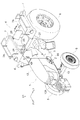
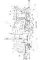
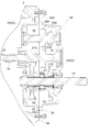
- FIG. 4 is a left side view of a main part showing the first embodiment and showing each operation structure of a sub-transmission unit and a PTO clutch. It is a perspective view of the principal part which shows 1st Embodiment and shows arrangement
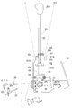
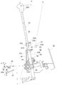
- FIG. 4 is a longitudinal left side view of a main part showing the first embodiment and showing a state in which the auxiliary transmission lever is located at a neutral position.
- FIG. 5 is a longitudinal left side view of a main part showing the first embodiment and showing a state in which the auxiliary transmission lever is located at a forward low speed position.
- FIG. 5 is a longitudinal left side view of the main part showing the first embodiment and showing a state in which the auxiliary transmission lever is located at the forward high speed position.
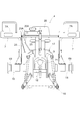
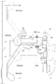
- FIG. 5 is a cross-sectional plan view of the main part showing the first embodiment and showing the positional relationship between the neutral position of the auxiliary transmission lever, the forward low speed position, the reverse drive position, the PTO clutch lever engagement position and the disengagement position.
- FIG. 5 is a cross-sectional plan view of the main part showing the first embodiment and showing the positional relationship between the neutral position of the auxiliary transmission lever, the forward high speed position, the PTO clutch lever entering position, and the cutting position.
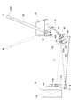
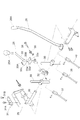
- It is a disassembled perspective view of the principal part which shows 1st Embodiment and shows the structure of a subtransmission lever and a PTO clutch lever.
- FIG. 4 is a longitudinal left side view of the main part showing the first embodiment and showing a state in which the housing unit is equipped with the PTO transmission.
- FIG. 3 is a longitudinal left side view of a main part showing the first embodiment and showing a state in which the forward / reverse switching device is mounted on the housing unit instead of the PTO transmission. It is a cross-sectional top view of the principal part which shows 1st Embodiment and shows the ventilation structure of a starter. It is a perspective view of the principal part which shows 1st Embodiment and shows the ventilation structure of a starter.
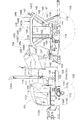
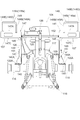
- FIG. 3 is a longitudinal plan view of a main part showing the rear axle support structure of the rear axle case according to the first embodiment. It is a perspective view which shows 2nd Embodiment and shows a tractor. It is a left view which shows 2nd Embodiment and shows a tractor.
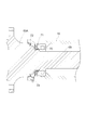
- FIG. 31 is a sectional view taken along the line XXXII-XXXII in FIG. 30.
- FIG. 31 is a sectional view taken along line XXXIII-XXXIII in FIG. 30.
- FIG. 31 is a sectional view taken along the line XXXIV-XXXIV in FIG. 30.
- the first embodiment will be described below.
- the direction indicated by the arrow F1 shown in FIG. 1 is the front side of the tractor
- the direction indicated by the arrow L1 is the left side of the tractor
- the direction indicated by the arrow U1 is the upper side of the tractor.
- the tractor exemplified in the first embodiment includes a driving unit 1 located in the front half of the vehicle body, a front frame 2 that supports the driving unit 1, a housing unit 3 that also serves as a rear frame, Covers the riding-type driving unit 4 located in the rear half of the vehicle body, the left and right front wheels 5 located on the left and right of the driving unit 1, the left and right rear wheels 6 located on the left and right of the driving unit 4, and the left and right rear wheels 6.
- the left and right rear fenders 7 are provided.
- the prime mover 1 includes an engine 8 located at the rear of the prime mover 1, a cooling fan 9 located in front of the engine 8, a radiator 10 located in front of the cooling fan 9, and the engine 8.
- a muffler 11 as an exhaust treatment device located on the left side, and a swingable bonnet 12 that covers them are provided.
- the cooling fan 9 takes outside air into the bonnet from an intake portion 12A provided at the front end of the bonnet 12, and supplies the taken outside air as cooling air to the radiator 10 and the engine 8 at the rear.
- the front frame 2 supports a left and right front wheel support member 13 that supports the left and right front wheels 5 via a support shaft 14 and the like that can be rolled.
- the housing unit 3 includes a working device (not shown) via a left and right rear axle case 15 extending left and right, a working device connecting link mechanism 16 and a link mechanism 16 at a rear portion thereof. And the like, and an electrohydraulic control type lifting unit 17 that lifts and lowers, and a PTO shaft 18 that makes it possible to take out working power to the working device.
- the housing unit 3 has an independent dual clutch 19 that intermittently supplies power from the engine 8, and power for traveling via the dual clutch 19. And a differential device (not shown) for the rear wheels, and a PTO transmission 21 that shifts the working power transmitted to the PTO shaft 18 via the dual clutch 19. Yes.
- the dual clutch 19 includes a traveling clutch 19A that interrupts power for traveling, and a PTO clutch 19B that intermittently transmits power to the PTO shaft 18.
- the transmission 20 includes a gear-type main transmission 20A and a gear-type sub-transmission 20B.
- the main transmission unit 20A shifts the driving power in four stages.
- the sub-transmission unit 20B switches the driving power between forward driving and reverse driving, and shifts the forward driving power to two levels.
- the PTO transmission 21 is a gear type that shifts working power to two stages of high and low.
- the driving unit 4 includes a steering wheel 23 for front wheel steering, a main transmission lever 24 that is an operation lever for a main transmission unit, an auxiliary transmission lever 25 that is an operation lever for an auxiliary transmission unit, A differential lock lever (not shown) as an operation lever for a differential device, a height setting lever (not shown) as an operation lever for an elevating unit, a PTO clutch lever 26 as an operation lever for a PTO clutch, and a PTO speed change gear.
- a PTO speed change lever (not shown) that is an operation lever for the device, a clutch pedal 27 for a travel clutch, and a driver seat 28 positioned between the left and right rear fenders 7 are provided.
- the main transmission lever 24 is disposed between the driver seat 28 and the right rear fender 7.
- the auxiliary transmission lever 25 and the PTO clutch lever 26 are arranged adjacent to each other between the driver seat 28 and the left rear fender 7 side by side.
- the housing unit 3 includes a support frame 29 on the left side of the front and rear intermediate portions.
- the support frame 29 includes a first support shaft 30 facing left and right and a lever guide 31 for the auxiliary transmission lever.
- the first support shaft 30 includes the auxiliary transmission lever 25 and the PTO clutch lever 26 as an inner operation lever in which the auxiliary transmission lever 25 is located on the driver seat side, and an outer operation lever in which the PTO clutch lever 26 is located on the rear fender side. With such an arrangement, it is supported so as to be swingable in the longitudinal direction of the vehicle body.
- the auxiliary transmission lever 25 includes a first member 32 on the base end side and a second member 33 on the free end side.
- the first member 32 is externally fitted to the first support shaft 30 so as to be able to swing back and forth.
- the second member 33 swings with respect to the first member 32 in the left-right direction with the second support shaft 34 facing forward and backward.
- the sub-shift lever 25 includes a neutral position, a forward low speed position positioned on the left side of the neutral position, a forward high speed position positioned on the right side of the neutral position, and a reverse position positioned on the left side of the neutral position. The swing operation to each operation position is possible.
- the second member 33 of the auxiliary transmission lever 25 is provided with a guided portion 33A at the proximal end thereof.
- the guided portion 33A is L-shaped in a left-right side view with the front wall 33a and upside down, and has a side wall 33b at the right end portion.
- the lever guide 31 includes front and rear guide pins 31A and 31B extending upward.
- the front and rear guide pins 31A and 31B have a front-rear interval that allows the guided portion 33A of the auxiliary transmission lever 25 to enter between them.
- the front and rear guide pins 31 ⁇ / b> A are set to the neutral position of the auxiliary transmission lever 25 between them.
- the front guide pin 31A prevents the auxiliary transmission lever 25 from swinging rightward from the forward low speed position by contact with the side wall 33b of the guided portion 33A.
- the front guide pin 31A prevents the auxiliary transmission lever 25 from swinging from the neutral position to the right front side by contact with the front wall 33a of the guided portion 33A.
- the rear guide pin 31B prevents the auxiliary transmission lever 25 from swinging left and right across the forward high speed position and the reverse movement position by contact with the side wall 33b of the guided portion 33A. That is, the auxiliary transmission lever 25 is provided with the guided portion 33A, and the front and rear guide pins 31A and 31B for restricting the movement of the guided portion 33A are simply provided on the support frame side.
- the second member 33 of the auxiliary transmission lever 25 is urged to swing to the left by the torsion spring 35. Accordingly, it is easy to perform a swing operation between the neutral position and the forward low speed position, which is frequently used during work travel, and a swing operation between the neutral position and the reverse position.
- the sub-transmission unit 20B can switch between the neutral state and the forward high speed state, and the first operation arm 20a that enables switching between the neutral state, the forward low speed state, and the reverse state.
- a second operating arm 20b can be linked to the first operating arm 20a can be linked to the second member 33 of the auxiliary transmission lever 25 via the first linkage mechanism 36 for auxiliary transmission.
- the second operating arm 20b can be linked to the second member 33 of the auxiliary transmission lever 25 via the second linkage mechanism 37 for auxiliary transmission.
- the second member 33 of the auxiliary transmission lever 25 includes a linkage portion 33B above the guided portion 33A.
- the linkage portion 33B is formed in an H shape in a plan view having concave portions 33c and 33d at both left and right ends.
- the first linkage mechanism 36 includes a first arm 38 that enters the recess 33c on the left side of the linkage portion 33B.
- the second linkage mechanism 37 includes a second arm 39 that enters the recess 33d on the right side of the linkage portion 33B.
- the first arm 38 is supported on the left end portion of the first support shaft 30 so as to be swingable back and forth.
- the second arm 39 is supported at the right end portion of the first support shaft 30 so as to be swingable back and forth.
- the auxiliary transmission lever 25 is linked to the first operating arm 20a via the first linkage mechanism 36.
- the sub-transmission unit 20B can be switched between a neutral state, a forward low-speed state, and a reverse state by operating the sub-transmission lever 25.
- the second member 33 is swung to the right in a state where the auxiliary transmission lever 25 is in the neutral position
- the second arm 39 enters the right recess 33d of the linkage portion 33B.
- the auxiliary transmission lever 25 is linked to the second operation arm 20b via the second linkage mechanism 37.
- the PTO clutch lever 26 is linked to the operation arm 19a of the PTO clutch 19B via the linkage mechanism 40 for the PTO clutch.
- the PTO clutch 19B includes a biasing means (not shown) for biasing the PTO clutch 19B back to the connected state.
- the linkage mechanism 40 includes a relay arm 42 that swings around a relay shaft 41 that faces left and right, a first rod 43 that extends between the PTO clutch lever 26 and the relay arm 42, and a second arm that extends between the operation arm 19 a and the relay arm 42.
- a rod 44 is provided.
- the linkage mechanism 40 switches the PTO clutch 19B to the connected state, and the pin 45 that connects the relay arm 42 and the second rod 44 includes a support shaft of the operation arm 19a. It is comprised so that it may be located under the virtual line L which connects 19b and the relay axis
- FIG. The linkage mechanism 40 is configured such that when the PTO clutch lever 26 is operated to the disengaged position, the PTO clutch 19B is switched to the disconnected state and the pin 45 is positioned above the imaginary line L.
- the relay shaft 41 is provided on the left side of the housing unit 3 together with the receiving member 46.
- the receiving member 46 receives the first receiving portion 46A that receives the relay arm 42 when the PTO clutch lever 26 reaches the entering position, and receives the relay arm 42 when the PTO clutch lever 26 reaches the cutting position. And a second receiving portion 46B.
- the PTO clutch 19B can be held in the disengaged state by the action of the biasing means and the receiving member 46 in the PTO clutch, and the PTO clutch lever 26 Can be held in the cutting position.
- the PTO clutch lever 26 has the auxiliary transmission lever 25 in a state where the entire gripping portion 26 A is positioned above the gripping portion 25 A of the auxiliary transmission lever 25. Is displaceable in the longitudinal direction of the vehicle body over a cutting position (first operation position) on the front side of the vehicle and an entry position (second operation position) on the rear side of the vehicle with respect to the operation range of the auxiliary transmission lever 25. And it is provided so that position holding is possible in the cutting position and the entering position. As a result, when the auxiliary transmission lever 25 is operated, the PTO clutch lever 26 is located at a cutting position or an entering position that deviates from the operation range of the auxiliary transmission lever 25 in the longitudinal direction of the vehicle body.
- auxiliary transmission lever 25 and the PTO clutch lever 26 are arranged adjacent to each other in the left and right in a narrow space between the driver seat 28 and the left rear fender 7, It is possible to avoid the possibility that the hand holding the holding portions 25A and 26A contacts the other levers 25 and 26. As a result, there is no need to increase the left-right distance between the left and right auxiliary transmission lever 25 and the PTO clutch lever 26. Therefore, in order to increase the left-right distance, the left and right rear fenders 7 are left and right. There is no need to take measures such as widening in the direction or complicated bending of the auxiliary transmission lever 25 and the PTO clutch lever 26 in the left-right direction. As a result, the auxiliary transmission lever 25 and the PTO clutch lever 26 are centrally arranged with good operability between the driver seat 28 and the left rear fender 7 without complicating the configuration and increasing the size of the vehicle body. can do.
- the auxiliary speed change lever 25 and the PTO clutch lever 26 swing in the longitudinal direction of the vehicle body with the common first support shaft 30 as a fulcrum.
- the PTO clutch lever 26 outside the vehicle body is configured to be longer than the auxiliary transmission lever 25 inside the vehicle body.
- the configuration is simplified as compared with the case where the auxiliary transmission lever 25 and the PTO clutch lever 26 are configured to be, for example, a front / rear slide type or a front / rear swing type individually having a dedicated support shaft. be able to.
- the entire gripping portion 26 ⁇ / b> A of the PTO clutch lever 26 can be positioned above the gripping portion 25 ⁇ / b> A of the sub-transmission lever 25 simply by making the PTO clutch lever 26 longer than the sub-transmission lever 25.
- the auxiliary transmission lever 25 and the PTO clutch lever 26 can be centrally arranged between the driver seat 28 and the left rear fender 7 with good operability while simplifying the configuration.
- the inner operation lever is the auxiliary transmission lever 25 and the outer operation lever is the PTO clutch lever 26.
- the auxiliary transmission portion 20B can be changed by a quick lever operation with a short operation stroke.
- the urging means in the PTO clutch is used to maintain the state in both the disconnected state and the connected state of the PTO clutch 19B, and the disengagement position of the PTO clutch lever 26.
- the PTO clutch lever 26 Since the position can be held at both the entering position, the switching operation between the disconnected state and the connected state of the PTO clutch 19B by the PTO clutch lever 26 becomes heavy. Considering this point, the PTO clutch lever 26 is made long, and this reduces the operating force required for the switching operation between the disconnected state and the connected state of the PTO clutch 19B by the PTO clutch lever 26. it can. As a result, the operability of the sub-transmission unit 20B by the sub-transmission lever 25 and the operability of the PTO clutch 19B by the PTO clutch lever 26 can be improved.
- the PTO clutch lever 26 is tilted toward the seat where the gripping portion 26 ⁇ / b> A is positioned closer to the driver's seat toward the upper side of the gripping portion 26 ⁇ / b> A.
- the posture is set.
- the gripping portion 26A of the PTO clutch lever 26 can be passed above the operation region of the auxiliary transmission lever 25.
- the space between the driver's seat 28 and the left rear fender 7 is narrowed, it is possible to avoid the possibility that the hand holding the grip portion 26A of the PTO clutch lever 26 located between them will contact the left rear fender 7. can do.
- the lateral width of the vehicle body can be narrowed without deteriorating the operability of the PTO clutch lever 26, which can be advantageous in terms of transportation of the tractor.
- the left and right rear fenders 7 have a mounting surface 7A at their upper ends.
- the upper end of the PTO clutch lever 26 is located on the lower side of the vehicle body than the placement surface 7A.
- the left and right rear fenders 7 can be effectively used for a mounting table for mounting other objects such as bags storing fertilizer or medicines consumed during work.
- the rear fender 7 in this way, it is possible to avoid the possibility that the hand holding the PTO clutch lever 26 or the holding portion 26A of the PTO clutch lever 26 will come into contact with other objects placed on the left rear fender 7. be able to.
- the PTO transmission 21 includes a PTO drive shaft 47, a PTO shaft 18, a low speed gear 48, a high speed gear 49, a shift member 50, a casing 51, and the like.
- the PTO drive shaft 47 has a low speed gear portion 47A that meshes with the low speed gear 48 and a high speed gear portion 47B that meshes with the high speed gear 49.
- the low speed gear 48 and the high speed gear 49 are fitted on the PTO shaft 18 so as to be relatively rotatable.
- the shift member 50 is fitted on the PTO shaft 18 so as to be relatively slidable in a state of rotating integrally with the PTO shaft 18.
- the PTO transmission 21 is in the low speed state when the low speed gear 48 is selected as the gear interlocked with the PTO shaft 18 by the sliding operation of the shift member 50, and the high speed when the high speed gear 49 is selected. It becomes a state.
- the casing 51 has a two-divided structure that can be divided into a front case 52 and a rear case 53.
- the rear case 53 has a flange 53A that is in surface contact with the rear end surface of the housing unit 3 in a waterproof state and is bolt-connected.
- the housing unit 3 has, at its rear end, an opening 3A that allows the front case 52 to enter, and a connecting portion 3B to which the flange 53A is bolted.
- the PTO drive shaft 47 is detachably connected to a work transmission shaft 55 in the housing unit via a cylindrical relay shaft 54. Thereby, the PTO transmission 21 can be attached to and detached from the housing unit 3 from the rear of the housing unit 3.
- this tractor is optionally provided with a forward / reverse switching device 56 that enables switching between the forward rotation driving state and the reverse rotation driving state of the PTO shaft 18.
- the forward / reverse switching device 56 includes a PTO drive shaft 57, a reverse rotation shaft 58, a PTO shaft 18, a normal rotation gear 59, a reverse rotation gear 60, a shift member 61, a casing 62, and the like.
- the PTO drive shaft 57 has a forward rotation gear portion 57A that meshes with the forward rotation gear 59 and a reverse rotation gear portion 57B.
- the reverse rotation shaft 58 includes a first reverse rotation gear portion 58A that meshes with the reverse rotation gear portion 57B, and a second reverse rotation gear portion 58B that meshes with the reverse rotation gear 60.
- the forward rotation gear 59 and the reverse rotation gear 60 are fitted on the PTO shaft 18 so as to be relatively rotatable.
- the shift member 61 is externally fitted to the PTO shaft 18 so as to be slidable relative to the PTO shaft 18 while rotating integrally with the PTO shaft 18.
- the forward / reverse switching device 56 enters the forward rotation drive state when the forward rotation gear 59 is selected as the gear interlocked with the PTO shaft 18 by the sliding operation of the shift member 61, and the reverse rotation gear 60 is selected. When it is done, it becomes a reverse rotation drive state.
- the casing 62 has a two-divided structure that can be divided into a front case 63 and a rear case 64.
- the rear case 64 has a flange 64 ⁇ / b> A that is bolted in surface contact with the rear end surface of the housing unit 3 in a waterproof state.
- the flange 64A is formed in the same shape as the flange 53A of the PTO transmission 21.
- the PTO drive shaft 57 can be detachably connected to the work transmission shaft 55 in the housing unit via a cylindrical relay shaft 54. Accordingly, the forward / reverse switching device 56 can be detachably attached to the housing unit 3 from the rear of the housing unit 3 instead of the PTO transmission 21.
- the PTO transmission lever is a PTO transmission linkage mechanism that extends from the PTO transmission lever to the operating arm of the PTO transmission 21.
- the PTO transmission lever By changing the state from the lever to the operating arm of the forward / reverse switching device 56, it can be used as a forward / reverse switching lever for PTO.
- the housing unit 3 is provided with a breather (not shown) for ventilation at the front upper part thereof.
- the housing unit 3 is connected to the engine 8 via the flywheel cover 65.
- the flywheel cover 65 is provided with a starter 66 for starting the engine in a waterproof state on the left side portion thereof.
- the starter 66 has an opening 66 ⁇ / b> A that allows the pinion gear 67 and the ring gear 68 of the engine 8 to mesh with each other.
- the starter 66 communicates with the interior of the housing unit 3 through the opening 66A. As a result, the starter 66 can be ventilated through the breather of the housing unit 3, the internal space of the housing unit 3, the opening 66 ⁇ / b> A of the starter 66, and the like.
- the left and right rear axle cases 15 are provided at their outer end portions with bearings 70 that support the outer end side of the rear axle 69, oil seals 71 with shafts that are adjacent to the outside of the vehicle body of the bearings 70, shafts A dust seal 72 located outside the vehicle body at a predetermined interval from the attached oil seal 71, a grease nipple 73 for injecting grease between the oil seal 71 with shaft and the dust seal 72, and the like are provided.
- the lubricating oil in the housing unit can be filled up to the location of the bearing 70 located on the outer end side of the left and right rear axle cases 15. Further, grease can be filled between the oil seal 71 with shaft and the dust seal 72. Further, it is possible to prevent the muddy water from entering the rear axle case. As a result, the durability of the rear axle 69 and the bearing 70 can be improved.
- the left and right rear axles 69 have large-diameter portions 69A that cover the dust seal 72 close to the inner peripheral surface of the rear axle case 15. As a result, intrusion into the rear axle case such as muddy water can be more effectively prevented. As a result, the durability of the rear axle 69 and the bearing 70 can be further improved.
- the plurality of operation levers 25 and 26 may be arranged adjacent to each other between the driver seat 28 and the right rear fender 7 side by side.
- the inner operation lever 25 may be a main transmission lever 24, a height setting lever, a PTO transmission lever, or the like.
- the outer operation lever 26 may be a differential lock lever, a PTO speed change lever, or the like.
- the outer operation lever 26 may be provided with an operation lever capable of switching and holding three positions in the longitudinal direction of the vehicle body, such as a forward / reverse switching lever.
- the outer operation lever 26 includes a first operation position on the front side of the vehicle body with respect to the operation range of the inner operation lever 25, a second operation position on the rear side of the vehicle body with respect to the operation range of the inner operation lever 25, and a second operation position. Further, it may be configured such that it can be displaced in the longitudinal direction of the vehicle body and can be held at each operation position over the third operation position on the rear side of the vehicle body.
- the outer operation lever 26 has a first operation position on the rear side of the vehicle body with respect to the operation range of the inner operation lever 25, a second operation position on the vehicle body front side with respect to the operation range of the inner operation lever 25, and a second operation position. Also, it may be configured to be displaceable in the longitudinal direction of the vehicle body and to be able to hold the position at each operation position over the third operation position on the front side of the vehicle body.
- the outer operation lever 26 includes an operation lever that can be switched and held at three positions in the longitudinal direction of the vehicle body, such as a forward / reverse switching lever, and the inner operation lever 25 has an operation range of the outer operation lever 26.
- a first inner operating lever 25 set between the first operating position and the second operating position, and an operating range set between the second operating position and the third operating position of the outer operating lever 26. 2 inner operation lever 25 may be provided.
- the outer operation lever 26 for example, a first outer operation lever 26 located on the rear fender side with respect to the inner operation lever 25, and a second outer operation lever located on the rear fender side with respect to the first outer operation lever 26, for example. 26 may be provided.
- the first outer operating lever 26 is located on the front side of the vehicle with respect to the operating range of the inner operating lever 25 in a state where the entire gripping portion 26A is positioned above the gripping portion 25A of the inner operating lever 25. It can be displaced in the longitudinal direction of the vehicle body over one operation position and the second operation position on the rear side of the vehicle body with respect to the operation range of the inner operation lever 25, and can be held at the first operation position and the second operation position. Is provided.
- the second outer operation lever 26 is located on the vehicle front side of the first operation position of the first outer operation lever 26 in a state where the entire gripping portion 26A is located above the gripping portion 26A of the first outer operation lever 26. Between the first operation position of the first outer operation lever 26 and the second operation position on the rear side of the vehicle body with respect to the second operation position of the first outer operation lever 26, and is displaceable in the longitudinal direction of the vehicle body and can be held at each operation position. It has been.
- the outer operation lever 26 and the inner operation lever 25 may be configured to swing in the longitudinal direction of the vehicle body with the dedicated left and right first support shaft 30 as a fulcrum.
- the outer operation lever 26 may be set such that the posture of the gripping portion 26 ⁇ / b> A extends straight along the rear fender 7.
- the upper end of the outer operation lever 26 may be positioned above the vehicle body with respect to the upper end of the rear fender 7.
- the upper end of the inner operation lever 25 and the outer operation lever 26 may be positioned above the vehicle body with respect to the upper end of the rear fender 7.
- the left and right rear fenders 7 may not have the mounting surface 7A at their upper ends.
- a plurality of operation levers are installed adjacent to each other in the left-right direction between the driver seat and the left and right rear fenders. There may be.
- the direction indicated by the arrow F2 shown in FIG. 20 is the front side of the tractor, the direction indicated by the arrow L2 is the left side of the tractor, and the direction indicated by the arrow U2 is the upper side of the tractor.
- the tractor illustrated in the second embodiment includes a driving unit 101 located in the front half of the vehicle body, a front frame 102 that supports the driving unit 101, a housing unit 103 that also serves as a rear frame, Covers the riding-type driving unit 104 located in the rear half of the vehicle body, the left and right front wheels 105 located on the left and right of the driving unit 101, the left and right rear wheels 106 located on the left and right of the driving unit 104, and the left and right rear wheels 106 Left and right rear fenders 107 are provided.
- the prime mover 101 includes an engine 108 located at the rear of the prime mover 101, a cooling fan 109 located in front of the engine 108, a radiator 110 located in front of the cooling fan 109, and an engine 108.
- a muffler 111 as an exhaust treatment device positioned on the upper left side, a resin fuel tank 111A, and a swingable bonnet 112 covering them are provided.
- the cooling fan 109 takes outside air into the bonnet 112 from an intake portion 112A provided at the front end of the bonnet 112, and supplies the taken outside air as cooling air to the rear radiator 110, the engine 108, and the like.
- the fuel tank 111 ⁇ / b> A has an L shape in a plan view extending from a space between the operating unit 104 and the engine 108 above the housing unit 103 to a space above the right side of the engine 108. Is formed.
- a heat shield plate 114 is disposed between the engine 108 and the fuel tank 111A.
- the heat shield plate 114 includes a flat surface portion 114A that also serves as a mounting table for the fuel tank 111A, a vertical wall portion 114B that also serves as a windbreak plate, and the like.
- the vertical wall portion 114 ⁇ / b> B is formed such that the lower end edge 114 a is recessed upward along the outer surface of the opposing housing unit 103. Thereby, the clearance gap formed between the lower end edge 114a of the vertical wall part 114B and the outer surface of the housing unit 103 can be made small.
- the vertical wall portion 114B of the heat shield plate 114 is also used as a windbreak plate to reduce the number of parts, the heated cooling air after engine cooling is generated from the gap between the vertical wall portion 114B and the housing unit 103. It is possible to make it difficult for the inconvenience to flow out to the operation unit side.
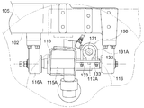
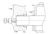
- the front frame 102 is provided with front and rear holders 116A for rotatably supporting a front and rear support shaft 115A at the bottom thereof.
- the support shaft 115A is fixed to the left and right center portion of the front wheel support member 113 facing left and right.
- the front wheel support member 113 supports the left and right front wheels 105 so that the left and right front wheels 105 can be steered.
- the front frame 102 supports the left and right front wheels 105 in a state in which rolling is possible with the support shaft 115A facing in the front-rear direction.
- the longitudinally supporting shaft 115A is equipped with a protective sleeve 118A at both ends thereof.
- the front and rear holders 116A include bushes 119 that are externally fitted to the sleeve 118A so as to be relatively rotatable.
- the housing unit 103 has a working device (not shown) via a left and right rear axle case 115 extending from side to side, a working device connecting link mechanism 116, and a link mechanism 116 at the rear part. And the like, and a PTO shaft 118 that makes it possible to take out working power to the working device.
- the driving unit 104 is disposed between the steering wheel 123 for front wheel steering, the main transmission lever 124, the auxiliary transmission lever 125, the PTO clutch lever 126, the clutch pedal 127, and the left and right rear fenders 107.
- a driver's seat 128 is provided.
- the steering wheel 123 is linked to the left and right front wheels 105 through an all-hydraulic power steering unit (hereinafter referred to as PS unit) 130.
- the PS unit 130 includes a double-acting steering cylinder 131 that steers the left and right front wheels 105, a control unit (not shown) that controls the flow of oil to the steering cylinder 131 in accordance with the operation of the steering wheel 23, and the like. I have.
- the steering cylinder 131 is fixed by the left and right U-bolts 132 and the four detent nuts 133 in a state where the cylinder tube 131A is placed on the left and right support portions 117A provided at the rear portion of the front wheel support member 13.
- the locking nut 133 for fixing the cylinder tube 131A the number of work steps required for fixing the cylinder tube 131A can be reduced compared to the case where a double nut is used instead of the locking nut 133. be able to.
- workability when the cylinder tube 131A of the steering cylinder 131 is fixed to the left and right support portions 117A is improved.
- the muffler 111 is provided with an exhaust pipe 134 extending from its exhaust part.
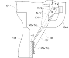
- the exhaust pipe 134 has an external exhaust part 134 ⁇ / b> A that extends long upward at the left outer portion of the bonnet 112.
- the lower end of the external exhaust part 134A is supported by a support arm 135 that extends from the left end of the front frame 102 toward the upper left.
- the support arm 135 includes a first strip steel plate 136 connected to the front frame 102, and a second strip steel plate 137 connected to the external exhaust part 134A.
- the first strip steel plate 136 has a vertically connecting portion 136A along the left side surface of the front frame 102, and an extending portion 136B extending straight from the upper end of the connecting portion 136A toward the upper left. .
- the first strip steel plate 136 is connected to the front frame 102 in a front-back orientation in which the band width direction is along the front-rear direction of the vehicle body.
- the second strip steel plate 137 is connected to the rear end of the first strip steel plate 136 such that the width direction of the second strip steel plate 137 is in the left-right orientation along the left-right direction of the vehicle body.
- the second strip steel plate 137 has an upper end portion 137A connected to the external exhaust portion 134A.
- the rear end edge 136a of the connecting portion 136A is welded to the right end edge 137a of the second strip steel plate 137.
- the lower end of the extension portion 136B is positioned at the upper end of the right end edge 137a of the second strip steel plate 137, and the upper end of the extension portion 136B is the upper end portion 137A of the second strip steel plate 137.
- the rear end edge 136b of the extending portion 136B is welded to the front surface 137b of the second strip-shaped steel plate 137 in a state where the rear end edge 136b is located closer to the left side than the center of the second strip-shaped steel plate 137.
- the support arm 135 and the external exhaust portion 134A are shared in the vehicle longitudinal direction. Shake easily occurs. As a result, stress concentration at the upper end portion 137A of the second strip steel plate 137 that is a connecting portion of the support arm 135 to the external exhaust portion 134A can be suppressed, and the upper end portion 137A due to the stress concentration can be suppressed. Generation of cracks can be prevented.
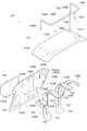
- the left and right rear axle cases 115 have a connecting portion 120A for the rear fender.
- the left and right rear fenders 107 are connected to the connecting portion 120A by an L-shaped connecting member 140 in the front-rear direction, the front and rear reinforcing members 141 extending between the flat portion 140A and the vertical wall portion 140B of the connecting member 140, and the connecting by the reinforcing members 141.
- Each reinforcing member 141 is formed in a hem-spread shape in which the left and right widths and the front and rear widths become wider toward the bottom.
- the support members 142 and 143 and the extending members 144 and 145 are vertically side plate support portions 142A to 145A to which the side plate 146 is welded, and left and right top plate support portions 142B to 142B to which the top plate 147 is welded. 145B.
- the left and right top plates 147 are each composed of a horizontal flat surface portion 147 A, a front extending portion 147 B extending from the front end of the flat surface portion 147 A to the front lower side, and A rear side extending portion 147C extending downward and rearward from the rear end of the flat surface portion 147A is provided.
- the left and right rear fenders 107 can also use the top plate 147 having the flat portion 147A as a mounting table on which a bag storing fertilizer or chemicals consumed during work is mounted.
- the left and right rear fenders 107 include guard members 148 that prevent the placed object from dropping outward from the left and right top plates 147.
- the left and right guard members 148 respectively include a front first leg portion 148A extending upward from the front extension portion 147B, a rear second leg portion 148B extending upward from the rear extension portion 147C, and The first leg 148A and the second leg 148B are bent so as to have a U-shaped guard part 148C in plan view.
- the front end guard part 148a facing left and right in each guard part 148C is located on the front side of the vehicle body from the front end of the plane part 147A.
- each guard portion 148C are located on the rear side of the vehicle body with respect to the rear end of the plane portion 147A.
- the convenience as a mounting table for each top plate 147 can be enhanced.
- the front end guard portion 148a of each guard member 148 is front and rear with respect to the driver that is easily gripped by the driver getting on and off the boarding / exiting portion 149 Since it is positioned closer to the boarding / exiting portion 149 than the front end of the flat surface portion 147A in the orientation posture (left-right orientation with respect to the vehicle body), the front end guard portion 148a can be used as a handrail for getting on and off. As a result, it is possible to improve boarding / exiting characteristics while simplifying the configuration.
- the left and right guard members 148 respectively include a front side third leg portion 148D and a rear side fourth leg portion 148E extending from the side end guard portion 148c to the plane portion 147A on the side end guard portion 148c facing in the front-rear direction of the guard portion 148C. Are connected. Thereby, the intensity
- the first leg portion 148A is fixed to the end portion on the driver seat side in the front extension portion 147B. Thereby, the length of the front end guard portion 148a can be increased, and the front end guard portion 148a can be easily used as a handrail for getting on and off.
- the first leg 148A is connected to the end on the driver seat side in the front end guard portion 148a. This makes it easier to grip the front end guard portion 148a than when the first leg portion 148A is connected to the left and right intermediate portions of the front end guard portion 148a, for example. As a result, the front end guard portion 148a can be easily used as a handrail for getting on and off.
- the left and right rear fenders 107 have a first reinforcing plate 150 welded across the front reinforcing member 141 and the first support member 142 on the outside of the vehicle body, A second reinforcing plate 151 welded over the rear reinforcing member 141 and the second support column member 143 is provided.
- the lower side of each rear fender 107 can be reinforced without providing a reinforcing member inside the vehicle body of each rear fender 107.
- each rear fender 107 can be reinforced to a high strength suitable for using each top plate 147 as a mounting table.
- the left and right side plates 146 are substantially triangular side walls 146 ⁇ / b> A surrounded by a second column member 143, a second extending member 145, and a top plate 147. Is provided with a connecting portion 146B to which a cross bar 152 extending between the left and right side plates 146 is connected.
- the left and right side plates 146 are formed with a plurality of reinforcing beads 146C. Thereby, it is possible to reinforce each side plate 146 to a high strength suitable for using each top plate 147 as a mounting table while preventing an increase in the number of parts.
- the reinforcing bead 146Ca located on the side wall portion 146A of each side plate 146 includes a second support member 143, a second extending member 145, and a connecting portion 146B. And is formed in a substantially triangular shape close to.
- the stress applied to the second support member 143 and the second extending member 145 can be dispersed in the connecting portion 146B with the cross bar 152, and the second support The load on the member 143 and the second extending member 145 can be reduced.
- the durability of each rear fender 107 can be improved while the top plate 147 of each rear fender 107 is also used as a mounting table.
- the front extending portion 147B of the left and right rear fenders 107 may have an arc shape that curves and extends downward from the front end of the flat surface portion 147A.
- the rear extension 147C in the left and right rear fenders 107 may have an arc shape that curves and extends rearward and downward from the rear end of the flat portion 147A.
- the first leg portion 148A may be connected to the left and right intermediate portion of the front end guard portion 148a.
- the second leg portion 148B may be connected to the left and right intermediate portion of the rear end guard portion 148b.
- a driver having a driver's seat, left and right rear fenders that are located on lateral sides of the driver's seat and have a top plate also used as a mounting table, and the left and right top plates
- Other riding work vehicles such as a riding mower and a riding rice transplanter, provided with left and right guard members that prevent the mounted article from falling outward.
- the first embodiment, the second embodiment, another embodiment of the first embodiment, and another embodiment of the second embodiment can be selectively combined as long as no contradiction arises.
- Various embodiments can be configured. Further, the scope of the present invention is not limited to the contents of the above embodiments.
Landscapes
- Engineering & Computer Science (AREA)
- Mechanical Engineering (AREA)
- Chemical & Material Sciences (AREA)
- Combustion & Propulsion (AREA)
- Transportation (AREA)
- Life Sciences & Earth Sciences (AREA)
- Soil Sciences (AREA)
- Environmental Sciences (AREA)
- Arrangement Or Mounting Of Control Devices For Change-Speed Gearing (AREA)
- Body Structure For Vehicles (AREA)
Abstract
複数の操作レバーを、それらの構成の複雑化、及び、車体の大型化を招くことなく、運転座席と左右一方のリアフェンダとの間に操作性良く集中配備できるようにする。 乗用作業車は、複数の操作レバー25,26が、運転座席と左右一方のリアフェンダ7との間に左右に並べて隣接配備され、複数の操作レバー25,26のうちの運転座席側に位置する内側操作レバー25は車体前後方向に変位可能に備えられ、複数の操作レバー25,26のうちのリアフェンダ側に位置する外側操作レバー26は、その把持部26Aの全体が内側操作レバー25の把持部25Aよりも車体上側に位置する状態で、内側操作レバー25の操作範囲よりも車体前側の第1操作位置と、内側操作レバー25の操作範囲よりも車体後側の第2操作位置とにわたって、車体前後方向に変位可能で、かつ、第1操作位置と第2操作位置とに位置保持可能に備えられている。
Description
本発明は、乗用作業車に関する。
〔背景技術1〕
乗用作業車の一例としては、複数の操作レバーとして、副変速レバーとPTO変速レバーとPTOオンオフレバーとを備えたトラクタがある(例えば日本国特許文献1参照)。このトラクタにおいて、各操作レバーは、車体における運転座席の左側方箇所に、PTO変速レバーの把持部とPTOオンオフレバーの把持部とが前後に並ぶ状態で運転座席側に位置するように配置設定されている。また、副変速レバーの把持部が、PTO変速レバーの把持部及びPTOオンオフレバーの把持部よりも車体横外側に位置するように配置設定されている。そして、このトラクタにおいては、例えば、副変速レバーの操作時に、副変速レバーの把持部を把持する手が、副変速レバーの把持部に隣接するPTO変速レバー又はPTOオンオフレバーに接触する虞を回避するために、副変速レバーと、PTO変速レバー及びPTOオンオフレバーと、の左右間隔を広くすることが考えられている。
乗用作業車の一例としては、複数の操作レバーとして、副変速レバーとPTO変速レバーとPTOオンオフレバーとを備えたトラクタがある(例えば日本国特許文献1参照)。このトラクタにおいて、各操作レバーは、車体における運転座席の左側方箇所に、PTO変速レバーの把持部とPTOオンオフレバーの把持部とが前後に並ぶ状態で運転座席側に位置するように配置設定されている。また、副変速レバーの把持部が、PTO変速レバーの把持部及びPTOオンオフレバーの把持部よりも車体横外側に位置するように配置設定されている。そして、このトラクタにおいては、例えば、副変速レバーの操作時に、副変速レバーの把持部を把持する手が、副変速レバーの把持部に隣接するPTO変速レバー又はPTOオンオフレバーに接触する虞を回避するために、副変速レバーと、PTO変速レバー及びPTOオンオフレバーと、の左右間隔を広くすることが考えられている。
〔背景技術2〕
また、乗用作業車としては、上下方向に延びる起立壁部と、起立壁部の上端部から車体横外側に前下がり傾斜姿勢で延びる第1延設部と、起立壁部の上端部から車体横外側に水平姿勢で延びる第2延設部と、起立壁部の上端部から車体横外側に後下がり傾斜姿勢で延びる第3延設部とを有する左右のフェンダ、第1延設部の中間部と第2延設部の前端部とに前後向き姿勢でわたる左右の第1ガード体、及び、第2延設部の前端部と後端部とにわたる平面視U字状の左右の第2ガード体、を備えるものがある(例えば日本国特許文献2参照)。この乗用作業車では、各第2延設部が載置台に兼用され、各第1ガード体が乗降用の手摺りとして機能し、各第2ガード体が、第2延設部から外方への載置物の落下を防止するガード部材として機能するように構成されている。
また、乗用作業車としては、上下方向に延びる起立壁部と、起立壁部の上端部から車体横外側に前下がり傾斜姿勢で延びる第1延設部と、起立壁部の上端部から車体横外側に水平姿勢で延びる第2延設部と、起立壁部の上端部から車体横外側に後下がり傾斜姿勢で延びる第3延設部とを有する左右のフェンダ、第1延設部の中間部と第2延設部の前端部とに前後向き姿勢でわたる左右の第1ガード体、及び、第2延設部の前端部と後端部とにわたる平面視U字状の左右の第2ガード体、を備えるものがある(例えば日本国特許文献2参照)。この乗用作業車では、各第2延設部が載置台に兼用され、各第1ガード体が乗降用の手摺りとして機能し、各第2ガード体が、第2延設部から外方への載置物の落下を防止するガード部材として機能するように構成されている。
上記〔背景技術1〕に対応する〔課題1〕は、以下のとおりである。
上記のように左右に並ぶ操作レバーの左右間隔を広くするためには、各操作レバーが配置される空間として、左右方向に広い空間を確保する必要がある。そのため、例えば、各操作レバーの配置箇所が運転座席と左右一方のリアフェンダとの間である場合には、運転座席と左右一方のリアフェンダとの間を左右方向に広くする必要がある。その結果、車体の左右幅が広くなって車体が大型化する不都合を招くことになる。
上記のように左右に並ぶ操作レバーの左右間隔を広くするためには、各操作レバーが配置される空間として、左右方向に広い空間を確保する必要がある。そのため、例えば、各操作レバーの配置箇所が運転座席と左右一方のリアフェンダとの間である場合には、運転座席と左右一方のリアフェンダとの間を左右方向に広くする必要がある。その結果、車体の左右幅が広くなって車体が大型化する不都合を招くことになる。
そこで、日本国特許文献1に記載のトラクタにおいては、各操作レバーの把持部が左側のリアフェンダの上方に位置するように構成することで、運転座席と左右一方のリアフェンダとの間を左右方向に広げることなく、左右に隣接する操作レバーの左右間隔を広げられるようにし、左右に隣接する操作レバーの一方の把持部を把持する手が他方の操作レバーに接触する虞を回避している。
しかしながら、日本国特許文献1に記載の構成では、各操作レバーの基部が運転座席と左側のリアフェンダとの間に位置し、かつ、各操作レバーの把持部が左側のリアフェンダの上方に位置するように、各操作レバーを複雑に屈曲させる必要が生じる。そのため、各操作レバーの構成の簡素化を図る上において改善の余地がある。
つまり、複数の操作レバーを、それらの構成の複雑化、及び、車体の大型化を招くことなく、運転座席と左右一方のリアフェンダとの間に操作性良く集中配備することが望まれている。
上記〔背景技術2〕に対応する〔課題2〕は、以下のとおりである。
日本国特許文献2に記載の構成では、各第2ガード体が、第2延設部の前端部と後端部とにわたる平面視U字状であることから、各リアフェンダには、第2延設部の前後長さよりも長い載置物を載置することができなくなっている。そのため、各リアフェンダを載置台として利用する上において利便性の面で改善の余地がある。
日本国特許文献2に記載の構成では、各第2ガード体が、第2延設部の前端部と後端部とにわたる平面視U字状であることから、各リアフェンダには、第2延設部の前後長さよりも長い載置物を載置することができなくなっている。そのため、各リアフェンダを載置台として利用する上において利便性の面で改善の余地がある。
また、第1ガード体が、リアフェンダの直前に位置する乗降部から乗降する運転者が把持し難い運転者に対する左右向き姿勢であることから、第1ガード体を乗降用の手摺りとして使用し難くなっている。そのため、乗降性の面で改善の余地がある。
つまり、上記のような乗用作業車においては、各リアフェンダを載置台として利用する上での利便性の改善、及び、乗降性の改善が望まれている。
上記〔課題1〕に対応する解決手段は、以下のとおりである。
すなわち、本発明に係る乗用作業車は、
運転座席と、前記運転座席の横側方箇所に位置する左右のリアフェンダと、複数の操作レバーとを備え、
複数の前記操作レバーは、前記運転座席と左右一方の前記リアフェンダとの間に左右に並べて隣接配備され、
複数の前記操作レバーのうちの運転座席側に位置する内側操作レバーは車体前後方向に変位可能に備えられ、
複数の前記操作レバーのうちのリアフェンダ側に位置する外側操作レバーは、その把持部の全体が前記内側操作レバーの把持部よりも車体上側に位置する状態で、前記内側操作レバーの操作範囲よりも車体前側の第1操作位置と、前記内側操作レバーの操作範囲よりも車体後側の第2操作位置とにわたって、車体前後方向に変位可能で、かつ、前記第1操作位置と前記第2操作位置とに位置保持可能に備えられている。
すなわち、本発明に係る乗用作業車は、
運転座席と、前記運転座席の横側方箇所に位置する左右のリアフェンダと、複数の操作レバーとを備え、
複数の前記操作レバーは、前記運転座席と左右一方の前記リアフェンダとの間に左右に並べて隣接配備され、
複数の前記操作レバーのうちの運転座席側に位置する内側操作レバーは車体前後方向に変位可能に備えられ、
複数の前記操作レバーのうちのリアフェンダ側に位置する外側操作レバーは、その把持部の全体が前記内側操作レバーの把持部よりも車体上側に位置する状態で、前記内側操作レバーの操作範囲よりも車体前側の第1操作位置と、前記内側操作レバーの操作範囲よりも車体後側の第2操作位置とにわたって、車体前後方向に変位可能で、かつ、前記第1操作位置と前記第2操作位置とに位置保持可能に備えられている。
この手段によると、内側操作レバーが操作される場合には、外側操作レバーが、内側操作レバーの操作範囲から車体前後方向に外れた第1操作位置又は第2操作位置に位置していることから、内側操作レバーと外側操作レバーとの左右間隔を広くすることなく、内側操作レバーの把持部を把持する手が、外側操作レバーに接触する虞を回避することができる。
また、外側操作レバーが操作される場合には、外側操作レバーの把持部の全体が内側操作レバーの把持部よりも車体上側に位置していることから、内側操作レバーと外側操作レバーとの左右間隔を広くすることなく、外側操作レバーの把持部を把持する手が、内側操作レバーに接触する虞を回避することができる。
つまり、運転座席と左右一方のリアフェンダとの間の左右幅の狭い空間において、複数の操作レバーが左右に隣接して並んでいても、その一つの操作レバーの把持部を把持する手が他の操作レバーに接触する虞を回避することができる。
これにより、左右に隣接する操作レバーの左右間隔を広くする必要がなくなる。よって、左右間隔を広くするために、運転座席と左右一方のリアフェンダとの間を左右方向に広くする、又は、各操作レバーを左右方向に複雑に屈曲させる、といった手段を講じる必要もなくなる。
その結果、複数の操作レバーを、それらの構成の複雑化、及び、車体の大型化を招くことなく、運転座席と左右一方のリアフェンダとの間に操作性良く集中配備することができる。
本発明をより好適にするための手段の一つとして、
前記外側操作レバー及び前記内側操作レバーは、共通の左右向きの支軸を支点にして車体前後方向に揺動し、
前記外側操作レバーは前記内側操作レバーよりも長尺である。
前記外側操作レバー及び前記内側操作レバーは、共通の左右向きの支軸を支点にして車体前後方向に揺動し、
前記外側操作レバーは前記内側操作レバーよりも長尺である。
この手段によると、複数の操作レバーを、例えば、前後スライド式、又は、個々に専用の支軸を有する前後揺動式、とする場合に比較して、構成の簡素化を図ることができる。そして、前後揺動式の外側操作レバーを内側操作レバーよりも長尺にするだけで、外側操作レバーの把持部の全体を内側操作レバーの把持部よりも車体上側に位置させることができる。
その結果、構成の簡素化を図りながら、複数の操作レバーを、運転座席と左右一方のリアフェンダとの間に操作性良く集中配備することができる。
本発明をより好適にするための手段の一つとして、
走行用の変速装置と、作業動力取り出し用のPTO軸への伝動を断続するPTOクラッチとを備え、
前記内側操作レバーは、前記変速装置の変速操作を可能にする変速レバーであり、
前記外側操作レバーは、前記PTOクラッチの断続操作を可能にするPTOクラッチレバーである。
走行用の変速装置と、作業動力取り出し用のPTO軸への伝動を断続するPTOクラッチとを備え、
前記内側操作レバーは、前記変速装置の変速操作を可能にする変速レバーであり、
前記外側操作レバーは、前記PTOクラッチの断続操作を可能にするPTOクラッチレバーである。
この手段によると、他の操作レバーの操作領域を跨ぐ必要のない内側操作レバーが変速レバーであることから、操作ストロークの短い迅速なレバー操作で、変速装置の変速操作を行える。
PTOクラッチは、PTOクラッチを接続状態に復帰付勢する付勢手段を備えることから、少なくとも接続状態から遮断状態への切り替え操作が重くなる。
この点を考慮して、PTOクラッチレバーを長尺にしているのであり、これにより、PTOクラッチの遮断状態への切り替え操作に要する操作力を軽減することができる。
その結果、各操作レバーによる変速装置及びPTOクラッチの操作性を向上させることができる。
本発明をより好適にするための手段の一つとして、
前記外側操作レバーは、その前記把持部の姿勢が、該把持部の上側ほど運転座席側に位置する座席側傾倒姿勢に設定されている。
前記外側操作レバーは、その前記把持部の姿勢が、該把持部の上側ほど運転座席側に位置する座席側傾倒姿勢に設定されている。
この手段によると、外側操作レバーの操作時には、外側操作レバーの把持部を、内側操作レバーの操作領域の上方を通過させることができる。これにより、運転座席と左右一方のリアフェンダとの間を狭くしても、それらの間に位置する外側操作レバーの把持部を把持する手がリアフェンダに接触する虞を回避することができる。
その結果、外側操作レバーの操作性を低下させることなく、車体の左右幅を狭くすることができ、乗用作業車の輸送などの面において有利にすることができる。
本発明をより好適にするための手段の一つとして、
前記リアフェンダは、その上端に載置面を有し、
前記外側操作レバーは、その上端が前記載置面よりも車体下側に位置している。
前記リアフェンダは、その上端に載置面を有し、
前記外側操作レバーは、その上端が前記載置面よりも車体下側に位置している。
この手段によると、例えば、乗用作業車がトラクタなどの農用作業車である場合には、リアフェンダを、作業時に消費する肥料又は薬剤などを貯留した袋などの他物を載置する載置台に有効利用することができる。そして、このようにしながらも、外側操作レバー又は外側操作レバーの把持部を把持する手が、リアフェンダに載置した他物に接触する虞を回避することができる。
その結果、外側操作レバーの操作性を低下させることなく、リアフェンダを載置台に有効利用することによる作業効率の向上などを図ることができる。
上記〔課題2〕に対応する解決手段は、以下のとおりである。
すなわち、本発明に係る乗用作業車は、
運転座席を有する運転部と、前記運転座席の横側方箇所に位置して天板が載置台に兼用される左右のリアフェンダと、左右の前記天板から外方への載置物の落下を防止する左右のガード部材とを備え、
左右の前記天板は、それぞれ、水平の平面部と、前記平面部の前端から前下方に延出する前側延出部と、前記平面部の後端から後下方に延出する後側延出部とを有し、
左右の前記ガード部材は、それぞれ、前記前側延出部から上方に延出する前側の第1脚部と、前記後側延出部から上方に延出する後側の第2脚部と、前記第1脚部と前記第2脚部とにわたる平面視U字状のガード部とを有して、前記ガード部における左右向きの前端ガード部分が、前記平面部の前端よりも車体前側に位置し、かつ、前記ガード部における左右向きの後端ガード部分が、前記平面部の後端よりも車体後側に位置している。
すなわち、本発明に係る乗用作業車は、
運転座席を有する運転部と、前記運転座席の横側方箇所に位置して天板が載置台に兼用される左右のリアフェンダと、左右の前記天板から外方への載置物の落下を防止する左右のガード部材とを備え、
左右の前記天板は、それぞれ、水平の平面部と、前記平面部の前端から前下方に延出する前側延出部と、前記平面部の後端から後下方に延出する後側延出部とを有し、
左右の前記ガード部材は、それぞれ、前記前側延出部から上方に延出する前側の第1脚部と、前記後側延出部から上方に延出する後側の第2脚部と、前記第1脚部と前記第2脚部とにわたる平面視U字状のガード部とを有して、前記ガード部における左右向きの前端ガード部分が、前記平面部の前端よりも車体前側に位置し、かつ、前記ガード部における左右向きの後端ガード部分が、前記平面部の後端よりも車体後側に位置している。
この手段によると、天板の平面部の前後長さよりも長い載置物を、天板に載置することが可能になる。その結果、各天板の載置台としての利便性を高めることができる。
また、運転者が各リアフェンダの直前に位置する乗降部から乗降する場合には、各ガード部材の前端ガード部分が、乗降部から乗降する運転者が把持し易い運転者に対する前後向き姿勢で、平面部の前端よりも乗降部の近くに位置することから、前端ガード部分を乗降用の手摺りとして利用することができる。その結果、構成の簡素化を図りながら、乗降性を向上させることができる。
本発明をより好適にするための手段の一つとして、
前記第1脚部は、前記前端ガード部分における運転座席側の端部に連接されている。
前記第1脚部は、前記前端ガード部分における運転座席側の端部に連接されている。
この手段によると、例えば、第1脚部が前端ガード部分の左右中間部に連接される場合に比較して、前端ガード部分に対する把持が行い易くなる。その結果、前端ガード部分を乗降用の手摺りとして利用し易くなる。
以下、本発明を実施するための形態の一例として、本発明を、乗用作業車の一例であるトラクタに適用した実施形態を図面に基づいて説明する。
〔第1実施形態〕
以下、第1実施形態について説明する。
尚、図1に記載した符号F1の矢印が指し示す方向がトラクタの前側であり、符号L1の矢印が指し示す方向がトラクタの左側であり、符号U1の矢印が指し示す方向がトラクタの上側である。
以下、第1実施形態について説明する。
尚、図1に記載した符号F1の矢印が指し示す方向がトラクタの前側であり、符号L1の矢印が指し示す方向がトラクタの左側であり、符号U1の矢印が指し示す方向がトラクタの上側である。
図1~4に示すように、本第1実施形態で例示するトラクタは、車体の前半部に位置する原動部1、原動部1を支持する前部フレーム2、後部フレームを兼ねるハウジングユニット3、車体の後半部に位置する搭乗式の運転部4、原動部1の左右に位置する左右の前輪5、運転部4の左右に位置する左右の後輪6、及び、左右の後輪6を覆う左右のリアフェンダ7、などを備えている。
図1~3に示すように、原動部1は、原動部1の後部に位置するエンジン8、エンジン8の前方に位置する冷却ファン9、冷却ファン9の前方に位置するラジエータ10、エンジン8の左側に位置する排気処理装置としてのマフラ11、及び、それらを覆う揺動開閉式のボンネット12、などを備えている。冷却ファン9は、その作動により、外気を、ボンネット12の前端部に備えた吸気部12Aからボンネット内に取り込み、取り込んだ外気を、冷却風として後方のラジエータ10及びエンジン8などに供給する。
前部フレーム2は、左右の前輪5を支持する左右向きの前輪支持部材13を、前後向きの支軸14などを介してローリング可能に支持している。
図2~4に示すように、ハウジングユニット3は、その後部に、左右に延出する左右の後車軸ケース15、作業装置連結用のリンク機構16、リンク機構16を介して作業装置(図示せず)を昇降駆動する電子油圧制御式の昇降ユニット17、及び、作業装置への作業動力の取り出しを可能にするPTO軸18、などを備えている。
図2及び図4~6に示すように、ハウジングユニット3は、その内部に、エンジン8からの動力を断続するインディペンデント式のデュアルクラッチ19、デュアルクラッチ19を経由した走行用の動力を変速する変速装置20、後輪用の差動装置(図示せず)、及び、デュアルクラッチ19を経由してPTO軸18に伝達される作業用の動力を変速するPTO変速装置21、などを備えている。
デュアルクラッチ19は、走行用の動力を断続する走行クラッチ19Aと、PTO軸18への伝動を断続するPTOクラッチ19Bとを備えている。変速装置20は、ギア式の主変速部20A及びギア式の副変速部20Bなどを備えている。主変速部20Aは、走行用の動力を4段に変速する。副変速部20Bは、走行用の動力を前進用と後進用とに切り替え、かつ、前進用の動力を高低2段に変速する。PTO変速装置21は、ギア式で作業用の動力を高低2段に変速する。
図1~4に示すように、運転部4は、前輪操舵用のステアリングホイール23、主変速部用の操作レバーである主変速レバー24、副変速部用の操作レバーである副変速レバー25、差動装置用の操作レバーであるデフロックレバー(図示せず)、昇降ユニット用の操作レバーである高さ設定レバー(図示せず)、PTOクラッチ用の操作レバーであるPTOクラッチレバー26、PTO変速装置用の操作レバーであるPTO変速レバー(図示せず)、走行クラッチ用のクラッチペダル27、及び、左右のリアフェンダ7の間に位置する運転座席28、などを備えている。
主変速レバー24は、運転座席28と右側のリアフェンダ7との間に配備されている。副変速レバー25及びPTOクラッチレバー26は、運転座席28と左側のリアフェンダ7との間に左右に並べて隣接配備されている。
図5~14に示すように、ハウジングユニット3は、その前後中間部の左側部に支持フレーム29を備えている。支持フレーム29は、左右向きの第1支軸30と副変速レバー用のレバーガイド31とを備えている。第1支軸30は、副変速レバー25及びPTOクラッチレバー26を、副変速レバー25が運転座席側に位置する内側操作レバーとなり、また、PTOクラッチレバー26がリアフェンダ側に位置する外側操作レバーとなる配置で、車体前後方向に揺動可能に支持している。
図6~14に示すように、副変速レバー25は、基端側の第1部材32と遊端側の第2部材33とを備えている。第1部材32は、第1支軸30に前後揺動可能に外嵌している。第2部材33は、第1部材32に対して前後向きの第2支軸34を支点にして左右方向に揺動する。
これにより、副変速レバー25は、中立位置、中立位置の左側前方に位置する前進低速位置、中立位置の右側後方に位置する前進高速位置、及び、中立位置の左側後方に位置する後進位置、の各操作位置への揺動操作が可能となっている。
これにより、副変速レバー25は、中立位置、中立位置の左側前方に位置する前進低速位置、中立位置の右側後方に位置する前進高速位置、及び、中立位置の左側後方に位置する後進位置、の各操作位置への揺動操作が可能となっている。
図6~12及び図14に示すように、副変速レバー25の第2部材33は、その基端側の端部に被案内部33Aを備えている。被案内部33Aは、左側面視の形状が前壁33aを有する上下逆向きのL形で、右端部位に側壁33bを有している。
レバーガイド31は、上方に延出する前後のガイドピン31A,31Bを備えている。前後のガイドピン31A,31Bは、それらの間に副変速レバー25の被案内部33Aが入り込むことを許容する前後間隔を有している。前後のガイドピン31Aは、それらの間が副変速レバー25の中立位置に設定されている。前側のガイドピン31Aは、被案内部33Aの側壁33bとの接触により、副変速レバー25の前進低速位置から右方への揺動を阻止している。前側のガイドピン31Aは、被案内部33Aの前壁33aとの接触により、副変速レバー25の中立位置から右側前方への揺動を阻止している。後側のガイドピン31Bは、被案内部33Aの側壁33bとの接触により、副変速レバー25の前進高速位置と後進位置とにわたる左右揺動を阻止している。
つまり、副変速レバー25に被案内部33Aを備え、かつ、被案内部33Aの移動を規制する前後のガイドピン31A,31Bを支持フレーム側に備えるだけの簡単な構成で、副変速レバー25の前進低速位置と前進高速位置と後進位置とにわたる揺動操作が必ず中立位置を経由して行われるように、副変速レバー25の操作経路をh形に設定するレバーガイド構造を得ることができる。
そして、副変速レバー25の操作経路をh形に設定する上において、h形のガイド溝を有するレバーガイドを組み付ける必要がなく、副変速レバー25をガイド溝に差し入れる必要がないことから、副変速レバー25の組み付けを容易にすることができる。
レバーガイド31は、上方に延出する前後のガイドピン31A,31Bを備えている。前後のガイドピン31A,31Bは、それらの間に副変速レバー25の被案内部33Aが入り込むことを許容する前後間隔を有している。前後のガイドピン31Aは、それらの間が副変速レバー25の中立位置に設定されている。前側のガイドピン31Aは、被案内部33Aの側壁33bとの接触により、副変速レバー25の前進低速位置から右方への揺動を阻止している。前側のガイドピン31Aは、被案内部33Aの前壁33aとの接触により、副変速レバー25の中立位置から右側前方への揺動を阻止している。後側のガイドピン31Bは、被案内部33Aの側壁33bとの接触により、副変速レバー25の前進高速位置と後進位置とにわたる左右揺動を阻止している。
つまり、副変速レバー25に被案内部33Aを備え、かつ、被案内部33Aの移動を規制する前後のガイドピン31A,31Bを支持フレーム側に備えるだけの簡単な構成で、副変速レバー25の前進低速位置と前進高速位置と後進位置とにわたる揺動操作が必ず中立位置を経由して行われるように、副変速レバー25の操作経路をh形に設定するレバーガイド構造を得ることができる。
そして、副変速レバー25の操作経路をh形に設定する上において、h形のガイド溝を有するレバーガイドを組み付ける必要がなく、副変速レバー25をガイド溝に差し入れる必要がないことから、副変速レバー25の組み付けを容易にすることができる。
図8~14に示すように、副変速レバー25の第2部材33は、ねじりバネ35により左側に揺動付勢されている。これにより、作業走行時に使用頻度の多い副変速レバー25の中立位置と前進低速位置とにわたる揺動操作、及び、中立位置と後進位置とにわたる揺動操作が行い易くなっている。
図6~14に示すように、副変速部20Bは、その中立状態と前進低速状態と後進状態との切り替えを可能にする第1操作アーム20aと、中立状態と前進高速状態との切り替えを可能にする第2操作アーム20bとを備えている。第1操作アーム20aは、副変速用の第1連係機構36を介して副変速レバー25の第2部材33に連係することができる。第2操作アーム20bは、副変速用の第2連係機構37を介して副変速レバー25の第2部材33に連係することができる。副変速レバー25の第2部材33は、被案内部33Aの上方に連係部33Bを備えている。連係部33Bは、左右両端に凹部33c,33dを有する平面視H形に形成されている。第1連係機構36は、連係部33Bの左側の凹部33cに入り込む第1アーム38を備えている。第2連係機構37は、連係部33Bの右側の凹部33dに入り込む第2アーム39を備えている。第1アーム38は、第1支軸30の左端部に前後揺動可能に支持されている。第2アーム39は、第1支軸30の右端部に前後揺動可能に支持されている。
この構成により、副変速レバー25が中立位置に位置する状態において、第2部材33が左側に揺動操作されると、連係部33Bの左側の凹部33cに第1アーム38が入り込む。これにより、副変速レバー25は、第1連係機構36を介して第1操作アーム20aに連係される。その結果、副変速レバー25の操作による副変速部20Bの中立状態と前進低速状態と後進状態との切り替えが可能になる。
逆に、副変速レバー25が中立位置に位置する状態において、第2部材33が右側に揺動操作されると、連係部33Bの右側の凹部33dに第2アーム39が入り込む。これにより、副変速レバー25は、第2連係機構37を介して第2操作アーム20bに連係される。その結果、副変速レバー25の操作による副変速部20Bの中立状態と前進高速状態との切り替えが可能になる。
この構成により、副変速レバー25が中立位置に位置する状態において、第2部材33が左側に揺動操作されると、連係部33Bの左側の凹部33cに第1アーム38が入り込む。これにより、副変速レバー25は、第1連係機構36を介して第1操作アーム20aに連係される。その結果、副変速レバー25の操作による副変速部20Bの中立状態と前進低速状態と後進状態との切り替えが可能になる。
逆に、副変速レバー25が中立位置に位置する状態において、第2部材33が右側に揺動操作されると、連係部33Bの右側の凹部33dに第2アーム39が入り込む。これにより、副変速レバー25は、第2連係機構37を介して第2操作アーム20bに連係される。その結果、副変速レバー25の操作による副変速部20Bの中立状態と前進高速状態との切り替えが可能になる。
図5~8及び図12~14に示すように、PTOクラッチレバー26は、PTOクラッチ用の連係機構40を介してPTOクラッチ19Bの操作アーム19aに連係されている。PTOクラッチ19Bは、PTOクラッチ19Bを接続状態に復帰付勢する付勢手段(図示せず)を内蔵している。連係機構40は、左右向きの中継軸41を支点にして揺動する中継アーム42、PTOクラッチレバー26と中継アーム42とにわたる第1ロッド43、及び、操作アーム19aと中継アーム42とにわたる第2ロッド44、などを備えている。連係機構40は、PTOクラッチレバー26が入り位置に操作されると、PTOクラッチ19Bを接続状態に切り替えるとともに、中継アーム42と第2ロッド44とを連結するピン45が、操作アーム19aの支軸19bと中継軸41とを結ぶ仮想線Lの下方に位置するように構成されている。連係機構40は、PTOクラッチレバー26が切り位置に操作されると、PTOクラッチ19Bを遮断状態に切り替えるとともに、ピン45が仮想線Lの上方に位置するように構成されている。中継軸41は、受止部材46とともにハウジングユニット3の左側部に備えられている。受止部材46は、PTOクラッチレバー26の入り位置への到達に伴って中継アーム42を受け止める第1受止部46Aと、PTOクラッチレバー26の切り位置への到達に伴って中継アーム42を受け止める第2受止部46Bとを有している。
この構成により、PTOクラッチレバー26が入り位置に操作されると、PTOクラッチ内の付勢手段及び受止部材46の作用により、PTOクラッチ19Bを接続状態に保持することができるとともに、PTOクラッチレバー26を入り位置に保持することができる。逆に、PTOクラッチレバー26が切り位置に操作されると、PTOクラッチ内の付勢手段及び受止部材46の作用により、PTOクラッチ19Bを遮断状態に保持することができるとともに、PTOクラッチレバー26を切り位置に保持することができる。
この構成により、PTOクラッチレバー26が入り位置に操作されると、PTOクラッチ内の付勢手段及び受止部材46の作用により、PTOクラッチ19Bを接続状態に保持することができるとともに、PTOクラッチレバー26を入り位置に保持することができる。逆に、PTOクラッチレバー26が切り位置に操作されると、PTOクラッチ内の付勢手段及び受止部材46の作用により、PTOクラッチ19Bを遮断状態に保持することができるとともに、PTOクラッチレバー26を切り位置に保持することができる。
図6~8、図12及び図13に示すように、PTOクラッチレバー26は、その把持部26Aの全体が副変速レバー25の把持部25Aよりも車体上側に位置する状態で、副変速レバー25の操作範囲よりも車体前側の切り位置(第1操作位置)と、副変速レバー25の操作範囲よりも車体後側の入り位置(第2操作位置)とにわたって、車体前後方向に変位可能で、かつ、切り位置と入り位置とに位置保持可能に備えられている。
これにより、副変速レバー25が操作される場合には、PTOクラッチレバー26が、副変速レバー25の操作範囲から車体前後方向に外れた切り位置又は入り位置に位置していることから、副変速レバー25とPTOクラッチレバー26との左右間隔を広くすることなく、副変速レバー25の把持部25Aを把持する手が、PTOクラッチレバー26に接触する虞を回避することができる。
また、PTOクラッチレバー26が操作される場合には、PTOクラッチレバー26の把持部26Aの全体が副変速レバー25の把持部25Aよりも車体上側に位置していることから、副変速レバー25とPTOクラッチレバー26との左右間隔を広くすることなく、PTOクラッチレバー26の把持部26Aを把持する手が、副変速レバー25に接触する虞を回避することができる。
つまり、運転座席28と左側のリアフェンダ7との間の左右幅の狭い空間において、副変速レバー25とPTOクラッチレバー26とが左右に隣接して並んでいても、その一方のレバー25,26の把持部25A,26Aを把持する手が他のレバー25,26に接触する虞を回避することができる。
これにより、左右に隣接する副変速レバー25とPTOクラッチレバー26との左右間隔を広くする必要がなくなり、よって、左右間隔を広くするために、運転座席28と左側のリアフェンダ7との間を左右方向に広くする、又は、副変速レバー25及びPTOクラッチレバー26を左右方向に複雑に屈曲させる、といった手段を講じる必要もなくなる。
その結果、副変速レバー25とPTOクラッチレバー26とを、それらの構成の複雑化、及び、車体の大型化を招くことなく、運転座席28と左側のリアフェンダ7との間に操作性良く集中配備することができる。
これにより、副変速レバー25が操作される場合には、PTOクラッチレバー26が、副変速レバー25の操作範囲から車体前後方向に外れた切り位置又は入り位置に位置していることから、副変速レバー25とPTOクラッチレバー26との左右間隔を広くすることなく、副変速レバー25の把持部25Aを把持する手が、PTOクラッチレバー26に接触する虞を回避することができる。
また、PTOクラッチレバー26が操作される場合には、PTOクラッチレバー26の把持部26Aの全体が副変速レバー25の把持部25Aよりも車体上側に位置していることから、副変速レバー25とPTOクラッチレバー26との左右間隔を広くすることなく、PTOクラッチレバー26の把持部26Aを把持する手が、副変速レバー25に接触する虞を回避することができる。
つまり、運転座席28と左側のリアフェンダ7との間の左右幅の狭い空間において、副変速レバー25とPTOクラッチレバー26とが左右に隣接して並んでいても、その一方のレバー25,26の把持部25A,26Aを把持する手が他のレバー25,26に接触する虞を回避することができる。
これにより、左右に隣接する副変速レバー25とPTOクラッチレバー26との左右間隔を広くする必要がなくなり、よって、左右間隔を広くするために、運転座席28と左側のリアフェンダ7との間を左右方向に広くする、又は、副変速レバー25及びPTOクラッチレバー26を左右方向に複雑に屈曲させる、といった手段を講じる必要もなくなる。
その結果、副変速レバー25とPTOクラッチレバー26とを、それらの構成の複雑化、及び、車体の大型化を招くことなく、運転座席28と左側のリアフェンダ7との間に操作性良く集中配備することができる。
図6~8及び図12~14に示すように、副変速レバー25及びPTOクラッチレバー26は、共通の第1支軸30を支点にして車体前後方向に揺動する。車体外側のPTOクラッチレバー26は、車体内側の副変速レバー25よりも長尺に構成されている。
これにより、副変速レバー25及びPTOクラッチレバー26を、例えば、前後スライド式、又は、個々に専用の支軸を有する前後揺動式、に構成する場合に比較して、構成の簡素化を図ることができる。そして、PTOクラッチレバー26を副変速レバー25よりも長尺にするだけで、PTOクラッチレバー26の把持部26Aの全体を副変速レバー25の把持部25Aよりも車体上側に位置させることができる。
その結果、構成の簡素化を図りながら、副変速レバー25及びPTOクラッチレバー26を、運転座席28と左側のリアフェンダ7との間に操作性良く集中配備することができる。
これにより、副変速レバー25及びPTOクラッチレバー26を、例えば、前後スライド式、又は、個々に専用の支軸を有する前後揺動式、に構成する場合に比較して、構成の簡素化を図ることができる。そして、PTOクラッチレバー26を副変速レバー25よりも長尺にするだけで、PTOクラッチレバー26の把持部26Aの全体を副変速レバー25の把持部25Aよりも車体上側に位置させることができる。
その結果、構成の簡素化を図りながら、副変速レバー25及びPTOクラッチレバー26を、運転座席28と左側のリアフェンダ7との間に操作性良く集中配備することができる。
前述したように、運転座席28と左側のリアフェンダ7との間に配備する2つの操作レバーのうち、内側操作レバーが副変速レバー25であり、外側操作レバーがPTOクラッチレバー26である。
つまり、PTOクラッチレバー26の操作領域を跨ぐ必要のない内側操作レバーが副変速レバー25であることから、操作ストロークの短い迅速なレバー操作で、副変速部20Bの変速操作を行える。
また、前述したように、このトラクタでは、PTOクラッチ内の付勢手段を利用して、PTOクラッチ19Bの遮断状態と接続状態との双方での状態保持、及び、PTOクラッチレバー26の切り位置と入り位置との双方での位置保持を可能にしていることから、PTOクラッチレバー26によるPTOクラッチ19Bの遮断状態と接続状態との切り替え操作が重くなる。
この点を考慮して、PTOクラッチレバー26を長尺にしているのであり、これにより、PTOクラッチレバー26によるPTOクラッチ19Bの遮断状態と接続状態との切り替え操作に要する操作力を軽減することができる。
その結果、副変速レバー25による副変速部20Bの操作性、及び、PTOクラッチレバー26によるPTOクラッチ19Bの操作性を向上させることができる。
つまり、PTOクラッチレバー26の操作領域を跨ぐ必要のない内側操作レバーが副変速レバー25であることから、操作ストロークの短い迅速なレバー操作で、副変速部20Bの変速操作を行える。
また、前述したように、このトラクタでは、PTOクラッチ内の付勢手段を利用して、PTOクラッチ19Bの遮断状態と接続状態との双方での状態保持、及び、PTOクラッチレバー26の切り位置と入り位置との双方での位置保持を可能にしていることから、PTOクラッチレバー26によるPTOクラッチ19Bの遮断状態と接続状態との切り替え操作が重くなる。
この点を考慮して、PTOクラッチレバー26を長尺にしているのであり、これにより、PTOクラッチレバー26によるPTOクラッチ19Bの遮断状態と接続状態との切り替え操作に要する操作力を軽減することができる。
その結果、副変速レバー25による副変速部20Bの操作性、及び、PTOクラッチレバー26によるPTOクラッチ19Bの操作性を向上させることができる。
図3、図4、図7、図8及び図12~14に示すように、PTOクラッチレバー26は、把持部26Aの姿勢が、その把持部26Aの上側ほど運転座席側に位置する座席側傾倒姿勢に設定されている。
これにより、PTOクラッチレバー26の操作時には、PTOクラッチレバー26の把持部26Aを、副変速レバー25の操作領域の上方を通過させることができる。これにより、運転座席28と左側のリアフェンダ7との間を狭くしても、それらの間に位置するPTOクラッチレバー26の把持部26Aを把持する手が、左側のリアフェンダ7に接触する虞を回避することができる。
その結果、PTOクラッチレバー26の操作性を低下させることなく、車体の左右幅を狭くすることができ、このトラクタの輸送などの面において有利にすることができる。
これにより、PTOクラッチレバー26の操作時には、PTOクラッチレバー26の把持部26Aを、副変速レバー25の操作領域の上方を通過させることができる。これにより、運転座席28と左側のリアフェンダ7との間を狭くしても、それらの間に位置するPTOクラッチレバー26の把持部26Aを把持する手が、左側のリアフェンダ7に接触する虞を回避することができる。
その結果、PTOクラッチレバー26の操作性を低下させることなく、車体の左右幅を狭くすることができ、このトラクタの輸送などの面において有利にすることができる。
図1~4及び図6~8に示すように、左右のリアフェンダ7は、その上端に載置面7Aを有している。PTOクラッチレバー26は、その上端が載置面7Aよりも車体下側に位置している。
これにより、例えば、左右のリアフェンダ7を、作業時に消費する肥料又は薬剤などを貯留した袋などの他物を載置する載置台に有効利用することができる。そして、このようにリアフェンダ7を有効利用しながらも、PTOクラッチレバー26又はPTOクラッチレバー26の把持部26Aを把持する手が、左側のリアフェンダ7に載置した他物に接触する虞を回避することができる。
その結果、PTOクラッチレバー26の操作性を低下させることなく、左右のリアフェンダ7を載置台に有効利用することによる作業効率の向上などを図ることができる。
これにより、例えば、左右のリアフェンダ7を、作業時に消費する肥料又は薬剤などを貯留した袋などの他物を載置する載置台に有効利用することができる。そして、このようにリアフェンダ7を有効利用しながらも、PTOクラッチレバー26又はPTOクラッチレバー26の把持部26Aを把持する手が、左側のリアフェンダ7に載置した他物に接触する虞を回避することができる。
その結果、PTOクラッチレバー26の操作性を低下させることなく、左右のリアフェンダ7を載置台に有効利用することによる作業効率の向上などを図ることができる。
図15に示すように、PTO変速装置21は、PTO駆動軸47、PTO軸18、低速ギア48、高速ギア49、シフト部材50、及び、ケーシング51、などを備えている。PTO駆動軸47は、低速ギア48と噛み合う低速ギア部47Aと、高速ギア49と噛み合う高速ギア部47Bとを有している。低速ギア48及び高速ギア49は、PTO軸18に相対回転可能に外嵌されている。シフト部材50は、PTO軸18と一体回転する状態で、PTO軸18に相対摺動可能に外嵌されている。
これにより、PTO変速装置21は、シフト部材50の摺動操作により、PTO軸18と連動するギアとして、低速ギア48が選択された場合に低速状態となり、高速ギア49が選択された場合に高速状態となる。
これにより、PTO変速装置21は、シフト部材50の摺動操作により、PTO軸18と連動するギアとして、低速ギア48が選択された場合に低速状態となり、高速ギア49が選択された場合に高速状態となる。
ケーシング51は、前ケース52と後ケース53とに分割可能な2分割構造である。後ケース53は、ハウジングユニット3の後端面に防水状態で面接触してボルト連結されるフランジ53Aを有している。ハウジングユニット3は、その後端に、前ケース52の入り込みを許容する開口3Aと、フランジ53Aがボルト連結される連結部3Bとを有している。PTO駆動軸47は、筒状の中継軸54を介して、ハウジングユニット内の作業用伝動軸55に着脱可能に接続されている。
これにより、PTO変速装置21は、ハウジングユニット3に対してハウジングユニット3の後方からの着脱が可能となっている。
これにより、PTO変速装置21は、ハウジングユニット3に対してハウジングユニット3の後方からの着脱が可能となっている。
図16に示すように、このトラクタは、PTO軸18の正回転駆動状態と逆回転駆動状態との切り替えを可能にする正逆転切替装置56をオプションとして備えている。正逆転切替装置56は、PTO駆動軸57、逆回転軸58、PTO軸18、正回転ギア59、逆回転ギア60、シフト部材61、及び、ケーシング62、などを備えている。PTO駆動軸57は、正回転ギア59と噛み合う正回転ギア部57Aと、逆回転ギア部57Bとを有している。逆回転軸58は、逆回転ギア部57Bと噛み合う第1逆回転ギア部58Aと、逆回転ギア60と噛み合う第2逆回転ギア部58Bとを有している。正回転ギア59及び逆回転ギア60は、PTO軸18に相対回転可能に外嵌されている。シフト部材61は、PTO軸18と一体回転する状態で、PTO軸18に相対摺動可能に外嵌されている。
これにより、正逆転切替装置56は、シフト部材61の摺動操作により、PTO軸18と連動するギアとして、正回転ギア59が選択された場合に正回転駆動状態となり、逆回転ギア60が選択された場合に逆回転駆動状態となる。
これにより、正逆転切替装置56は、シフト部材61の摺動操作により、PTO軸18と連動するギアとして、正回転ギア59が選択された場合に正回転駆動状態となり、逆回転ギア60が選択された場合に逆回転駆動状態となる。
ケーシング62は、前ケース63と後ケース64とに分割可能な2分割構造である。後ケース64は、ハウジングユニット3の後端面に防水状態で面接触してボルト連結されるフランジ64Aを有している。フランジ64Aは、PTO変速装置21のフランジ53Aと同じ形状に形成されている。PTO駆動軸57は、筒状の中継軸54を介して、ハウジングユニット内の作業用伝動軸55に着脱可能に接続することができる。
これにより、正逆転切替装置56は、PTO変速装置21に代えて、ハウジングユニット3に対してハウジングユニット3の後方から着脱可能に取り付けることができる。
これにより、正逆転切替装置56は、PTO変速装置21に代えて、ハウジングユニット3に対してハウジングユニット3の後方から着脱可能に取り付けることができる。
図示は省略するが、PTO変速レバーは、PTO変速装置21を正逆転切替装置56に交換した場合には、PTO変速レバーからPTO変速装置21の操作アームにわたるPTO変速用の連係機構を、PTO変速レバーから正逆転切替装置56の操作アームにわたる状態に付け替えることにより、PTO用の正逆転切替レバーとして使用することができる。
図17及び図18に示すように、ハウジングユニット3は、その前上部に通気用のブリーザ(図示せず)を備えている。ハウジングユニット3は、フライホイールカバー65を介してエンジン8に接続されている。フライホイールカバー65は、その左側部位に、エンジン始動用のスタータ66を防水状態で備えている。スタータ66は、そのピニオンギア67とエンジン8のリングギア68との噛み合いを許容する開口66Aを有している。スタータ66は、その開口66Aを介して内部がハウジングユニット3の内部に連通している。
これにより、スタータ66に対する換気を、ハウジングユニット3のブリーザ、ハウジングユニット3の内部空間、及び、スタータ66の開口66A、などを介して行うことができる。
これにより、スタータ66に対する換気を、ハウジングユニット3のブリーザ、ハウジングユニット3の内部空間、及び、スタータ66の開口66A、などを介して行うことができる。
図19に示すように、左右の後車軸ケース15は、それらの外端部に、後車軸69の外端側を支持するベアリング70、ベアリング70の車体外側に隣接する軸付きオイルシール71、軸付きオイルシール71から所定間隔をあけた車体外側箇所に位置するダストシール72、及び、軸付きオイルシール71とダストシール72との間へのグリス注入用のグリスニップル73、などを備えている。
これにより、ハウジングユニット内の潤滑油を、左右の後車軸ケース15の外端側に位置するベアリング70の配置箇所まで満たすことができる。また、グリスを、軸付きオイルシール71とダストシール72との間に充填することができる。更に、泥水などの後車軸ケース内への浸入を防止することができる。その結果、後車軸69及びベアリング70などの耐久性の向上を図ることができる。
これにより、ハウジングユニット内の潤滑油を、左右の後車軸ケース15の外端側に位置するベアリング70の配置箇所まで満たすことができる。また、グリスを、軸付きオイルシール71とダストシール72との間に充填することができる。更に、泥水などの後車軸ケース内への浸入を防止することができる。その結果、後車軸69及びベアリング70などの耐久性の向上を図ることができる。
左右の後車軸69は、後車軸ケース15の内周面に近接して、ダストシール72を覆い隠す大径部69Aを有している。これにより、泥水などの後車軸ケース内への浸入をより効果的に防止することができる。その結果、後車軸69及びベアリング70などの耐久性を更に向上させることができる。
〔第1実施形態の別実施形態〕
以下、第1実施形態の代表的な別実施形態を例示する。
以下、第1実施形態の代表的な別実施形態を例示する。
〔1-1〕複数の操作レバー25,26は、運転座席28と右側のリアフェンダ7との間に左右に並べて隣接配備されていてもよい。
〔1-2〕内側操作レバー25は、主変速レバー24、高さ設定レバー、又は、PTO変速レバー、などであってもよい。
〔1-3〕外側操作レバー26は、デフロックレバー又はPTO変速レバーなどであってもよい。
〔1-4〕外側操作レバー26として、例えば前後進切替レバーなどのように車体前後方向に3位置切り替え保持可能な操作レバーを備えてもよい。
この場合、外側操作レバー26は、内側操作レバー25の操作範囲よりも車体前側の第1操作位置と、内側操作レバー25の操作範囲よりも車体後側の第2操作位置と、第2操作位置よりも車体後側の第3操作位置とにわたって、車体前後方向に変位可能で、かつ、各操作位置に位置保持可能に構成されていてもよい。
また、外側操作レバー26は、内側操作レバー25の操作範囲よりも車体後側の第1操作位置と、内側操作レバー25の操作範囲よりも車体前側の第2操作位置と、第2操作位置よりも車体前側の第3操作位置とにわたって、車体前後方向に変位可能で、かつ、各操作位置に位置保持可能に構成されていてもよい。
この場合、外側操作レバー26は、内側操作レバー25の操作範囲よりも車体前側の第1操作位置と、内側操作レバー25の操作範囲よりも車体後側の第2操作位置と、第2操作位置よりも車体後側の第3操作位置とにわたって、車体前後方向に変位可能で、かつ、各操作位置に位置保持可能に構成されていてもよい。
また、外側操作レバー26は、内側操作レバー25の操作範囲よりも車体後側の第1操作位置と、内側操作レバー25の操作範囲よりも車体前側の第2操作位置と、第2操作位置よりも車体前側の第3操作位置とにわたって、車体前後方向に変位可能で、かつ、各操作位置に位置保持可能に構成されていてもよい。
〔1-5〕外側操作レバー26として、例えば前後進切替レバーなどのように車体前後方向に3位置切り替え保持可能な操作レバーを備え、かつ、内側操作レバー25として、操作範囲が外側操作レバー26の第1操作位置と第2操作位置との間に設定される第1内側操作レバー25と、操作範囲が外側操作レバー26の第2操作位置と第3操作位置との間に設定される第2内側操作レバー25とを備えていてもよい。
〔1-6〕外側操作レバー26として、例えば、内側操作レバー25よりもリアフェンダ側に位置する第1外側操作レバー26と、第1外側操作レバー26よりもリアフェンダ側に位置する第2外側操作レバー26とを備えるようにしてもよい。
この構成において、第1外側操作レバー26は、その把持部26Aの全体が内側操作レバー25の把持部25Aよりも車体上側に位置する状態で、内側操作レバー25の操作範囲よりも車体前側の第1操作位置と、内側操作レバー25の操作範囲よりも車体後側の第2操作位置とにわたって、車体前後方向に変位可能で、かつ、第1操作位置と第2操作位置とに位置保持可能に備えられている。
第2外側操作レバー26は、その把持部26Aの全体が第1外側操作レバー26の把持部26Aよりも車体上側に位置する状態で、第1外側操作レバー26の第1操作位置よりも車体前側の第1操作位置と、第1外側操作レバー26の第2操作位置よりも車体後側の第2操作位置とにわたって、車体前後方向に変位可能で、かつ、各操作位置に位置保持可能に備えられている。
この構成において、第1外側操作レバー26は、その把持部26Aの全体が内側操作レバー25の把持部25Aよりも車体上側に位置する状態で、内側操作レバー25の操作範囲よりも車体前側の第1操作位置と、内側操作レバー25の操作範囲よりも車体後側の第2操作位置とにわたって、車体前後方向に変位可能で、かつ、第1操作位置と第2操作位置とに位置保持可能に備えられている。
第2外側操作レバー26は、その把持部26Aの全体が第1外側操作レバー26の把持部26Aよりも車体上側に位置する状態で、第1外側操作レバー26の第1操作位置よりも車体前側の第1操作位置と、第1外側操作レバー26の第2操作位置よりも車体後側の第2操作位置とにわたって、車体前後方向に変位可能で、かつ、各操作位置に位置保持可能に備えられている。
〔1-7〕外側操作レバー26と内側操作レバー25とが、それぞれ専用の左右向きの第1支軸30を支点にして車体前後方向に揺動する構成であってもよい。
〔1-8〕外側操作レバー26は、その把持部26Aの姿勢が、リアフェンダ7に沿って真直ぐに延出する姿勢に設定されていてもよい。
〔1-9〕外側操作レバー26は、その上端がリアフェンダ7の上端よりも車体上側に位置していてもよい。
〔1-10〕内側操作レバー25及び外側操作レバー26は、それらの上端がリアフェンダ7の上端よりも車体上側に位置していてもよい。
〔1-11〕左右のリアフェンダ7は、それらの上端に載置面7Aを有していなくてもよい。
〔1-12〕上記トラクタ以外にも、複数の操作レバーが運転座席と左右一方のリアフェンダとの間において左右方向に隣接配備された、例えば、乗用草刈機、乗用田植機などの乗用作業車であってもよい。
〔第2実施形態〕
以下、第2実施形態について説明する。
尚、図20に記載した符号F2の矢印が指し示す方向がトラクタの前側であり、符号L2の矢印が指し示す方向がトラクタの左側であり、符号U2の矢印が指し示す方向がトラクタの上側である。
以下、第2実施形態について説明する。
尚、図20に記載した符号F2の矢印が指し示す方向がトラクタの前側であり、符号L2の矢印が指し示す方向がトラクタの左側であり、符号U2の矢印が指し示す方向がトラクタの上側である。
図20~23に示すように、本第2実施形態で例示するトラクタは、車体の前半部に位置する原動部101、原動部101を支持する前部フレーム102、後部フレームを兼ねるハウジングユニット103、車体の後半部に位置する搭乗式の運転部104、原動部101の左右に位置する左右の前輪105、運転部104の左右に位置する左右の後輪106、及び、左右の後輪106を覆う左右のリアフェンダ107、などを備えている。
図20~22に示すように、原動部101は、原動部101の後部に位置するエンジン108、エンジン108の前方に位置する冷却ファン109、冷却ファン109の前方に位置するラジエータ110、エンジン108の左側上方に位置する排気処理装置としてのマフラ111、樹脂製の燃料タンク111A、及び、それらを覆う揺動開閉式のボンネット112、などを備えている。冷却ファン109は、その作動により、外気を、ボンネット112の前端部に備えた吸気部112Aからボンネット112内に取り込み、取り込んだ外気を、冷却風として後方のラジエータ110及びエンジン108などに供給する。
図21、図24及び図25に示すように、燃料タンク111Aは、ハウジングユニット103の上方における運転部104とエンジン108との間の空間から、エンジン108の右側上方の空間にわたる平面視L字状に形成されている。エンジン108と燃料タンク111Aとの間には、遮熱板114が配備されている。
遮熱板114は、燃料タンク111Aの載置台を兼ねる平面部114A、及び、防風板を兼ねる縦壁部114B、などを備えている。縦壁部114Bは、その下端縁114aが、対向するハウジングユニット103の外面に沿って上方に凹入するように形成されている。
これにより、縦壁部114Bの下端縁114aとハウジングユニット103の外面との間に形成される隙間を小さくすることができる。
つまり、遮熱板114の縦壁部114Bを防風板に兼用して部品点数の削減などを図りながら、エンジン冷却後の昇温した冷却風が、縦壁部114Bとハウジングユニット103との隙間から運転部側に流出する不都合を生じ難くすることができる。
これにより、縦壁部114Bの下端縁114aとハウジングユニット103の外面との間に形成される隙間を小さくすることができる。
つまり、遮熱板114の縦壁部114Bを防風板に兼用して部品点数の削減などを図りながら、エンジン冷却後の昇温した冷却風が、縦壁部114Bとハウジングユニット103との隙間から運転部側に流出する不都合を生じ難くすることができる。
図20、図21、図26及び図27に示すように、前部フレーム102は、その底部に、前後向きの支軸115Aを回転可能に支持する前後のホルダ116Aを備えている。支軸115Aは、左右向きの前輪支持部材113の左右中央箇所に固定されている。前輪支持部材113は、その左右両端部にて左右の前輪105を操舵可能に支持している。これにより、前部フレーム102は、左右の前輪105を、前後向きの支軸115Aを支点にしたローリングが可能な状態で支持している。
図27に示すように、前後向きの支軸115Aは、その両端部に保護用のスリーブ118Aが打ち込み装備されている。前後のホルダ116Aは、スリーブ118Aに相対回転可能に外嵌するブッシュ119を備えている。
これにより、各ホルダ116A内に泥水が浸入した場合には、その浸入に起因した摩耗がスリーブ118Aとブッシュ119との間において発生するようになり、泥水の浸入に起因した支軸115Aの摩耗を防止することができる。
その結果、各ホルダ116A内への泥水の浸入に起因した摩耗に対するメンテナンスは、支軸115Aよりも安価なスリーブ118A又はブッシュ119の交換で対処することができる。
これにより、各ホルダ116A内に泥水が浸入した場合には、その浸入に起因した摩耗がスリーブ118Aとブッシュ119との間において発生するようになり、泥水の浸入に起因した支軸115Aの摩耗を防止することができる。
その結果、各ホルダ116A内への泥水の浸入に起因した摩耗に対するメンテナンスは、支軸115Aよりも安価なスリーブ118A又はブッシュ119の交換で対処することができる。
図21~23に示すように、ハウジングユニット103は、その後部に、左右に延出する左右の後車軸ケース115、作業装置連結用のリンク機構116、リンク機構116を介して作業装置(図示せず)を昇降駆動する電子油圧制御式の昇降ユニット117、及び、作業装置への作業動力の取り出しを可能にするPTO軸118、などを備えている。
図20~23に示すように、運転部104は、前輪操舵用のステアリングホイール123、主変速レバー124、副変速レバー125、PTOクラッチレバー126、クラッチペダル127、及び、左右のリアフェンダ107の間に位置する運転座席128、などを備えている。
図20、図21及び図26に示すように、ステアリングホイール123は、全油圧式のパワーステアリングユニット(以下、PSユニットと称する)130を介して左右の前輪105に操作連係されている。PSユニット130は、左右の前輪105を操舵する複動型のステアリングシリンダ131、及び、ステアリングホイール23の操作に応じてステアリングシリンダ131に対するオイルの流れを制御するコントロールユニット(図示せず)、などを備えている。
ステアリングシリンダ131は、そのシリンダチューブ131Aが、前輪支持部材13の後部に備えた左右の支持部117Aに載置された状態で、左右のU字ボルト132、及び、4つの回り止めナット133により固定されている。
このように、シリンダチューブ131Aの固定に回り止めナット133を採用することにより、回り止めナット133の代わりにダブルナットを採用する場合に比較して、シリンダチューブ131Aの固定に要する作業工数を削減することができる。また、ナット締め付け時のトルク管理が行い易くなる。
その結果、ステアリングシリンダ131のシリンダチューブ131Aを左右の支持部117Aに固定する場合の作業性が向上する。また、ダブルナットを採用する場合に生じていた、シリンダチューブ131Aを固定する作業者によってナットの締め付け具合が異なることに起因して、ダブルナットによる十分な緩み止め効果が得られなくなる虞を回避することができる。
このように、シリンダチューブ131Aの固定に回り止めナット133を採用することにより、回り止めナット133の代わりにダブルナットを採用する場合に比較して、シリンダチューブ131Aの固定に要する作業工数を削減することができる。また、ナット締め付け時のトルク管理が行い易くなる。
その結果、ステアリングシリンダ131のシリンダチューブ131Aを左右の支持部117Aに固定する場合の作業性が向上する。また、ダブルナットを採用する場合に生じていた、シリンダチューブ131Aを固定する作業者によってナットの締め付け具合が異なることに起因して、ダブルナットによる十分な緩み止め効果が得られなくなる虞を回避することができる。
図20~22、図28及び図29に示すように、マフラ111は、その排気部から延出する排気管134を備えている。排気管134は、ボンネット112の左外側箇所において上方に長く延出する外部排気部134Aを有している。外部排気部134Aは、その下端部が、前部フレーム102の左端部から左上方に向けて延出する支持アーム135に支持されている。
図28及び図29に示すように、支持アーム135は、前部フレーム102に連結される第1帯状鋼板136と、外部排気部134Aに連結される第2帯状鋼板137とを備えている。第1帯状鋼板136は、前部フレーム102の左側面に沿う上下向きの連結部136Aと、連結部136Aの上端から左上方に向けて真直ぐに延出する延出部136Bとを有している。第1帯状鋼板136は、その帯幅方向が車体の前後方向に沿う前後向き姿勢で前部フレーム102に連結されている。第2帯状鋼板137は、その帯幅方向が車体の左右方向に沿う左右向き姿勢で、第1帯状鋼板136の後端に連接されている。第2帯状鋼板137は、その上端部137Aが外部排気部134Aに連結されている。
第1帯状鋼板136は、連結部136Aの後端縁136aが第2帯状鋼板137の右端縁137aに溶接されている。第1帯状鋼板136は、延出部136Bの下端が、第2帯状鋼板137における右端縁137aの上端に位置し、かつ、延出部136Bの上端が、第2帯状鋼板137の上端部137Aの近くで、第2帯状鋼板137の帯幅方向の中心よりも左側に位置する状態で、延出部136Bの後端縁136bが、第2帯状鋼板137の前面137bに溶接されている。
これにより、例えば、延出部136Bの後端縁136bを第2帯状鋼板137の右側上縁137cに溶接する場合に比較して、支持アーム135の外部排気部134Aとの車体前後方向への共揺れが生じ易くなる。
その結果、支持アーム135の外部排気部134Aとの連結部である第2帯状鋼板137の上端部137Aでの応力の集中を抑制することができ、その応力の集中に起因した上端部137Aでの亀裂の発生を防止することができる。
これにより、例えば、延出部136Bの後端縁136bを第2帯状鋼板137の右側上縁137cに溶接する場合に比較して、支持アーム135の外部排気部134Aとの車体前後方向への共揺れが生じ易くなる。
その結果、支持アーム135の外部排気部134Aとの連結部である第2帯状鋼板137の上端部137Aでの応力の集中を抑制することができ、その応力の集中に起因した上端部137Aでの亀裂の発生を防止することができる。
図20~23及び図30~34に示すように、左右の後車軸ケース115は、リアフェンダ用の連結部120Aを有している。左右のリアフェンダ107は、連結部120Aに連結される前後方向視L字状の連結部材140、連結部材140の平面部140Aと縦壁部140Bとにわたる前後の補強部材141、各補強部材141による連結部材140の補強箇所から上方に延出する前側の第1支柱部材142と後側の第2支柱部材143、第1支柱部材142から前上方に延出する第1延出部材144、第1支柱部材142から後上方に延出する第2延出部材145、後輪106を車体内側から覆う側板146、及び、後輪106を上方から覆う天板147、などを備えている。
各補強部材141は、下側ほど左右幅及び前後幅が広くなる裾広がり形状に形成されている。各支柱部材142,143及び各延出部材144,145は、側板146が溶接される縦向きの側板支持部142A~145A、及び、天板147が溶接される左右向きの天板支持部142B~145Bを有している。
図20~23、図30及び図31に示すように、左右の天板147は、それぞれ、水平の平面部147A、平面部147Aの前端から前下方に延出する前側延出部147B、及び、平面部147Aの後端から後下方に延出する後側延出部147C、などを有している。
これにより、左右のリアフェンダ107は、平面部147Aを有する天板147を、作業時に消費する肥料又は薬剤などを貯留した袋などを載置する載置台に兼用することができる。
これにより、左右のリアフェンダ107は、平面部147Aを有する天板147を、作業時に消費する肥料又は薬剤などを貯留した袋などを載置する載置台に兼用することができる。
左右のリアフェンダ107は、左右の天板147から外方への載置物の落下を防止するガード部材148を備えている。左右のガード部材148は、それぞれ、前側延出部147Bから上方に延出する前側の第1脚部148A、後側延出部147Cから上方に延出する後側の第2脚部148B、及び、第1脚部148Aと第2脚部148Bとにわたる平面視U字状のガード部148C、を有するように屈曲形成されている。そして、各ガード部148Cにおける左右向きの前端ガード部分148aが、平面部147Aの前端よりも車体前側に位置している。また、各ガード部148Cにおける左右向きの後端ガード部分148bが、平面部147Aの後端よりも車体後側に位置している。
これにより、天板147の平面部147Aの前後長さよりも長い載置物を、各天板147に載置することが可能になる。その結果、各天板147の載置台としての利便性を高めることができる。
また、運転者が各リアフェンダ107の直前に位置する乗降部149から乗降する場合には、各ガード部材148の前端ガード部分148aが、乗降部149から乗降する運転者が把持し易い運転者に対する前後向き姿勢(車体に対しては左右向き姿勢)で、平面部147Aの前端よりも乗降部149の近くに位置することから、前端ガード部分148aを乗降用の手摺りとして利用することができる。その結果、構成の簡素化を図りながら、乗降性を向上させることができる。
これにより、天板147の平面部147Aの前後長さよりも長い載置物を、各天板147に載置することが可能になる。その結果、各天板147の載置台としての利便性を高めることができる。
また、運転者が各リアフェンダ107の直前に位置する乗降部149から乗降する場合には、各ガード部材148の前端ガード部分148aが、乗降部149から乗降する運転者が把持し易い運転者に対する前後向き姿勢(車体に対しては左右向き姿勢)で、平面部147Aの前端よりも乗降部149の近くに位置することから、前端ガード部分148aを乗降用の手摺りとして利用することができる。その結果、構成の簡素化を図りながら、乗降性を向上させることができる。
左右のガード部材148は、それぞれ、ガード部148Cにおける前後向きの側端ガード部分148cに、側端ガード部分148cから平面部147Aにわたる前側の第3脚部148Dと後側の第4脚部148Eとが連接されている。これにより、ガード部材148としての強度を高めることができる。
図20、図22及び図31に示すように、第1脚部148Aは、前側延出部147Bにおける運転座席側の端部に固定されている。これにより、前端ガード部分148aの長さを長くすることでき、前端ガード部分148aを乗降用の手摺りとして利用し易くなる。
第1脚部148Aは、前端ガード部分148aにおける運転座席側の端部に連接されている。これにより、例えば、第1脚部148Aが前端ガード部分148aの左右中間部に連接される場合に比較して、前端ガード部分148aに対する把持が行い易くなる。その結果、前端ガード部分148aを乗降用の手摺りとして利用し易くなる。
図21、図23及び図30~32に示すように、左右のリアフェンダ107は、それらの車体外側において、前側の補強部材141と第1支柱部材142とにわたって溶接される第1補強プレート150と、後側の補強部材141と第2支柱部材143とにわたって溶接される第2補強プレート151とを備えている。
これにより、各リアフェンダ107の車体内側に補強部材を設けることなく、各リアフェンダ107の下部側を補強することができる。
その結果、左側のリアフェンダ107と運転座席128との間への副変速レバー125及びPTOクラッチレバー126の配備、及び、右側のリアフェンダ107と運転座席128との間への主変速レバー124の配備、などに支障を来すことなく、各リアフェンダ107の下部側を、各天板147を載置台として利用するのに適した高い強度に補強することができる。
これにより、各リアフェンダ107の車体内側に補強部材を設けることなく、各リアフェンダ107の下部側を補強することができる。
その結果、左側のリアフェンダ107と運転座席128との間への副変速レバー125及びPTOクラッチレバー126の配備、及び、右側のリアフェンダ107と運転座席128との間への主変速レバー124の配備、などに支障を来すことなく、各リアフェンダ107の下部側を、各天板147を載置台として利用するのに適した高い強度に補強することができる。
図22、図23、図30及び図31に示すように、左右の側板146は、第2支柱部材143と第2延出部材145と天板147とで囲まれた略三角形状の側壁部146Aの上端部位に、左右の側板146にわたるクロスバー152が連結される連結部146Bを備えている。
図30~33に示すように、左右の側板146には、複数の補強用のビード146Cが形成されている。これにより、部品点数の増加を防止しながら、各側板146を、各天板147を載置台として利用するのに適した高い強度に補強することができる。
図30及び図31に示すように、複数のビード146Cのうち、各側板146の側壁部146Aに位置する補強用のビード146Caは、第2支柱部材143と第2延出部材145と連結部146Bとに近接する略三角形状に形成されている。
これにより、天板147に載置物を載置した場合に、第2支柱部材143及び第2延出部材145にかかる応力をクロスバー152との連結部146Bに分散させることができ、第2支柱部材143及び第2延出部材145にかかる負荷を軽減することができる。
その結果、各リアフェンダ107の天板147を載置台に兼用しながら、各リアフェンダ107の耐久性を向上させることができる。
これにより、天板147に載置物を載置した場合に、第2支柱部材143及び第2延出部材145にかかる応力をクロスバー152との連結部146Bに分散させることができ、第2支柱部材143及び第2延出部材145にかかる負荷を軽減することができる。
その結果、各リアフェンダ107の天板147を載置台に兼用しながら、各リアフェンダ107の耐久性を向上させることができる。
〔第2実施形態の別実施形態〕
以下、第2実施形態の代表的な別実施形態を例示する。
以下、第2実施形態の代表的な別実施形態を例示する。
〔2-1〕左右のリアフェンダ107における前側延出部147Bは、平面部147Aの前端から前下方に湾曲して延出する円弧形状としてもよい。
〔2-2〕左右のリアフェンダ107における後側延出部147Cは、平面部147Aの後端から後下方に湾曲して延出する円弧形状としてもよい。
〔2-3〕第1脚部148Aは、前端ガード部分148aの左右中間部に連接されていてもよい。
〔2-4〕第2脚部148Bは、後端ガード部分148bの左右中間部に連接されていてもよい。
〔2-5〕上記トラクタ以外にも、運転座席を有する運転部と、前記運転座席の横側方箇所に位置して天板が載置台に兼用される左右のリアフェンダと、左右の前記天板から外方への載置物の落下を防止する左右のガード部材とを備えた、乗用草刈機、乗用田植機などの他の乗用作業車であってもよい。
尚、上記第1実施形態、第2実施形態、第1実施形態の別実施形態、第2実施形態の別実施形態は、矛盾が生じない限り、選択的に組み合わせることができ、これにより、様々な実施形態を構成できる。また、本発明の範囲は、上記各実施形態の内容に限定されるものではない。
〔第1実施形態〕
7 リアフェンダ
7A 載置面
18 PTO軸
19B PTOクラッチ
20 走行用の変速装置
25 操作レバー(内側操作レバー、変速レバー)
25A 把持部
26 操作レバー(外側操作レバー、PTOクラッチレバー)
26A 把持部
28 運転座席
30 支軸
〔第2実施形態〕
104 運転部
107 リアフェンダ
128 運転座席
147 天板
147A 平面部
147B 前側延出部
147C 後側延出部
148 ガード部材
148A 第1脚部
148B 第2脚部
148C ガード部
148a 前端ガード部分
148b 後端ガード部分
7 リアフェンダ
7A 載置面
18 PTO軸
19B PTOクラッチ
20 走行用の変速装置
25 操作レバー(内側操作レバー、変速レバー)
25A 把持部
26 操作レバー(外側操作レバー、PTOクラッチレバー)
26A 把持部
28 運転座席
30 支軸
〔第2実施形態〕
104 運転部
107 リアフェンダ
128 運転座席
147 天板
147A 平面部
147B 前側延出部
147C 後側延出部
148 ガード部材
148A 第1脚部
148B 第2脚部
148C ガード部
148a 前端ガード部分
148b 後端ガード部分
Claims (7)
- 運転座席と、前記運転座席の横側方箇所に位置する左右のリアフェンダと、複数の操作レバーとを備え、
複数の前記操作レバーは、前記運転座席と左右一方の前記リアフェンダとの間に左右に並べて隣接配備され、
複数の前記操作レバーのうちの運転座席側に位置する内側操作レバーは車体前後方向に変位可能に備えられ、
複数の前記操作レバーのうちのリアフェンダ側に位置する外側操作レバーは、その把持部の全体が前記内側操作レバーの把持部よりも車体上側に位置する状態で、前記内側操作レバーの操作範囲よりも車体前側の第1操作位置と、前記内側操作レバーの操作範囲よりも車体後側の第2操作位置とにわたって、車体前後方向に変位可能で、かつ、前記第1操作位置と前記第2操作位置とに位置保持可能に備えられている乗用作業車。 - 前記外側操作レバー及び前記内側操作レバーは、共通の左右向きの支軸を支点にして車体前後方向に揺動し、
前記外側操作レバーは前記内側操作レバーよりも長尺である請求項1に記載の乗用作業車。 - 走行用の変速装置と、作業動力取り出し用のPTO軸への伝動を断続するPTOクラッチとを備え、
前記内側操作レバーは、前記変速装置の変速操作を可能にする変速レバーであり、
前記外側操作レバーは、前記PTOクラッチの断続操作を可能にするPTOクラッチレバーである請求項2に記載の乗用作業車。 - 前記外側操作レバーは、その前記把持部の姿勢が、該把持部の上側ほど運転座席側に位置する座席側傾倒姿勢に設定されている請求項1~3のいずれか一つに記載の乗用作業車。
- 前記リアフェンダは、その上端に載置面を有し、
前記外側操作レバーは、その上端が前記載置面よりも車体下側に位置している請求項1~4のいずれか一つに記載の乗用作業車。 - 運転座席を有する運転部と、前記運転座席の横側方箇所に位置して天板が載置台に兼用される左右のリアフェンダと、左右の前記天板から外方への載置物の落下を防止する左右のガード部材とを備え、
左右の前記天板は、それぞれ、水平の平面部と、前記平面部の前端から前下方に延出する前側延出部と、前記平面部の後端から後下方に延出する後側延出部とを有し、
左右の前記ガード部材は、それぞれ、前記前側延出部から上方に延出する前側の第1脚部と、前記後側延出部から上方に延出する後側の第2脚部と、前記第1脚部と前記第2脚部とにわたる平面視U字状のガード部とを有して、前記ガード部における左右向きの前端ガード部分が、前記平面部の前端よりも車体前側に位置し、かつ、前記ガード部における左右向きの後端ガード部分が、前記平面部の後端よりも車体後側に位置している乗用作業車。 - 前記第1脚部は、前記前端ガード部分における運転座席側の端部に連接されている請求項6に記載の乗用作業車。
Priority Applications (2)
| Application Number | Priority Date | Filing Date | Title |
|---|---|---|---|
| CN201680056956.0A CN108025777B (zh) | 2015-09-29 | 2016-06-06 | 乘用作业车 |
| US15/762,835 US10625795B2 (en) | 2015-09-29 | 2016-06-06 | Riding work vehicle |
Applications Claiming Priority (4)
| Application Number | Priority Date | Filing Date | Title |
|---|---|---|---|
| JP2015-192059 | 2015-09-29 | ||
| JP2015192059A JP6541536B2 (ja) | 2015-09-29 | 2015-09-29 | 乗用作業車 |
| JP2015-192055 | 2015-09-29 | ||
| JP2015192055A JP6416073B2 (ja) | 2015-09-29 | 2015-09-29 | 乗用作業車 |
Publications (1)
| Publication Number | Publication Date |
|---|---|
| WO2017056563A1 true WO2017056563A1 (ja) | 2017-04-06 |
Family
ID=58423128
Family Applications (1)
| Application Number | Title | Priority Date | Filing Date |
|---|---|---|---|
| PCT/JP2016/066770 Ceased WO2017056563A1 (ja) | 2015-09-29 | 2016-06-06 | 乗用作業車 |
Country Status (3)
| Country | Link |
|---|---|
| US (1) | US10625795B2 (ja) |
| CN (1) | CN108025777B (ja) |
| WO (1) | WO2017056563A1 (ja) |
Families Citing this family (2)
| Publication number | Priority date | Publication date | Assignee | Title |
|---|---|---|---|---|
| JP7262278B2 (ja) * | 2019-04-01 | 2023-04-21 | 株式会社クボタ | 作業車の操作機構及び作業車 |
| JP6621959B1 (ja) * | 2019-08-09 | 2019-12-18 | 株式会社クボタ | 作業車両 |
Citations (7)
| Publication number | Priority date | Publication date | Assignee | Title |
|---|---|---|---|---|
| JPH10121933A (ja) * | 1996-10-23 | 1998-05-12 | Honda Motor Co Ltd | エンジンのオイル吸入構造 |
| JP2000203286A (ja) * | 1999-01-14 | 2000-07-25 | Yanmar Agricult Equip Co Ltd | 管理作業車 |
| JP2003291677A (ja) * | 2002-04-04 | 2003-10-15 | Kubota Corp | 変速操作装置 |
| JP2005186872A (ja) * | 2003-12-26 | 2005-07-14 | Kubota Corp | 作業車の運転部構造 |
| JP2006027571A (ja) * | 2004-07-21 | 2006-02-02 | Sugai Sogyo:Kk | 小型カート |
| JP2012051517A (ja) * | 2010-09-02 | 2012-03-15 | Yanmar Co Ltd | トラクタ |
| JP2014040143A (ja) * | 2012-08-21 | 2014-03-06 | Kubota Corp | 作業車 |
Family Cites Families (12)
| Publication number | Priority date | Publication date | Assignee | Title |
|---|---|---|---|---|
| JPS57130722U (ja) * | 1981-02-09 | 1982-08-14 | ||
| US6112139A (en) * | 1998-10-29 | 2000-08-29 | Case Corporation | Apparatus and method for wireless remote control of an operation of a work vehicle |
| JP4835239B2 (ja) * | 2006-04-06 | 2011-12-14 | スズキ株式会社 | 自動二輪車 |
| JP4996344B2 (ja) * | 2007-05-30 | 2012-08-08 | 株式会社クボタ | 作業車の操作構造 |
| JP5427100B2 (ja) | 2010-04-27 | 2014-02-26 | 株式会社クボタ | トラクタ |
| JP5319617B2 (ja) * | 2010-06-14 | 2013-10-16 | 株式会社クボタ | 作業車のレバー防塵構造 |
| JP5881385B2 (ja) * | 2011-11-24 | 2016-03-09 | 株式会社クボタ | 作業車の防塵構造 |
| JP6004977B2 (ja) * | 2013-03-22 | 2016-10-12 | 株式会社クボタ | 作業車 |
| JP6066808B2 (ja) | 2013-04-10 | 2017-01-25 | 株式会社クボタ | 作業車 |
| JP6386979B2 (ja) * | 2015-08-07 | 2018-09-05 | ヤンマー株式会社 | 作業車両 |
| US10480156B2 (en) * | 2015-12-14 | 2019-11-19 | Kubota Corporation | Work vehicle |
| JP6758173B2 (ja) * | 2016-12-16 | 2020-09-23 | 株式会社クボタ | 自動走行作業車 |
-
2016
- 2016-06-06 WO PCT/JP2016/066770 patent/WO2017056563A1/ja not_active Ceased
- 2016-06-06 US US15/762,835 patent/US10625795B2/en active Active
- 2016-06-06 CN CN201680056956.0A patent/CN108025777B/zh active Active
Patent Citations (7)
| Publication number | Priority date | Publication date | Assignee | Title |
|---|---|---|---|---|
| JPH10121933A (ja) * | 1996-10-23 | 1998-05-12 | Honda Motor Co Ltd | エンジンのオイル吸入構造 |
| JP2000203286A (ja) * | 1999-01-14 | 2000-07-25 | Yanmar Agricult Equip Co Ltd | 管理作業車 |
| JP2003291677A (ja) * | 2002-04-04 | 2003-10-15 | Kubota Corp | 変速操作装置 |
| JP2005186872A (ja) * | 2003-12-26 | 2005-07-14 | Kubota Corp | 作業車の運転部構造 |
| JP2006027571A (ja) * | 2004-07-21 | 2006-02-02 | Sugai Sogyo:Kk | 小型カート |
| JP2012051517A (ja) * | 2010-09-02 | 2012-03-15 | Yanmar Co Ltd | トラクタ |
| JP2014040143A (ja) * | 2012-08-21 | 2014-03-06 | Kubota Corp | 作業車 |
Also Published As
| Publication number | Publication date |
|---|---|
| US10625795B2 (en) | 2020-04-21 |
| CN108025777A (zh) | 2018-05-11 |
| CN108025777B (zh) | 2020-06-30 |
| US20180273119A1 (en) | 2018-09-27 |
Similar Documents
| Publication | Publication Date | Title |
|---|---|---|
| US10315709B2 (en) | Working vehicle | |
| US8690190B2 (en) | Work vehicle with engine mounted rearwardly | |
| US20180326845A1 (en) | Work vehicle | |
| US11267387B2 (en) | Work vehicle | |
| US9079491B2 (en) | Work vehicle | |
| CN108025777B (zh) | 乘用作业车 | |
| KR101789133B1 (ko) | 승용형 농작업기 | |
| CN101466567A (zh) | 操纵连杆结构 | |
| JP6541536B2 (ja) | 乗用作業車 | |
| JP5293017B2 (ja) | コンバイン | |
| JP6416073B2 (ja) | 乗用作業車 | |
| CN101179926B (zh) | 载人型插秧机 | |
| US11370289B2 (en) | Work vehicle | |
| JP3821680B2 (ja) | 草刈り機 | |
| KR101319896B1 (ko) | 승용형 이앙기 | |
| JP5901562B2 (ja) | 作業車 | |
| JP2010006268A (ja) | 作業車両 | |
| JP2003040149A (ja) | 乗用管理機 | |
| KR20240145878A (ko) | 작업 차량 | |
| JP2014008054A (ja) | 自走式作業車両 | |
| JP4044398B2 (ja) | 走行車両 | |
| JP2005218315A (ja) | モアー用トラクタ | |
| JP2015189379A (ja) | 作業車 | |
| JP2015191496A (ja) | 乗用作業車 | |
| JP2010215139A (ja) | 乗用型農作業機及び乗用型田植機 |
Legal Events
| Date | Code | Title | Description |
|---|---|---|---|
| 121 | Ep: the epo has been informed by wipo that ep was designated in this application |
Ref document number: 16850740 Country of ref document: EP Kind code of ref document: A1 |
|
| WWE | Wipo information: entry into national phase |
Ref document number: 15762835 Country of ref document: US |
|
| NENP | Non-entry into the national phase |
Ref country code: DE |
|
| 122 | Ep: pct application non-entry in european phase |
Ref document number: 16850740 Country of ref document: EP Kind code of ref document: A1 |