WO2017051812A1 - 車載用電源装置及びその制御方法 - Google Patents
車載用電源装置及びその制御方法 Download PDFInfo
- Publication number
- WO2017051812A1 WO2017051812A1 PCT/JP2016/077762 JP2016077762W WO2017051812A1 WO 2017051812 A1 WO2017051812 A1 WO 2017051812A1 JP 2016077762 W JP2016077762 W JP 2016077762W WO 2017051812 A1 WO2017051812 A1 WO 2017051812A1
- Authority
- WO
- WIPO (PCT)
- Prior art keywords
- switch
- power supply
- battery
- sub
- main battery
- Prior art date
- Legal status (The legal status is an assumption and is not a legal conclusion. Google has not performed a legal analysis and makes no representation as to the accuracy of the status listed.)
- Ceased
Links
Images


Classifications
-
- H—ELECTRICITY
- H02—GENERATION; CONVERSION OR DISTRIBUTION OF ELECTRIC POWER
- H02J—CIRCUIT ARRANGEMENTS OR SYSTEMS FOR SUPPLYING OR DISTRIBUTING ELECTRIC POWER; SYSTEMS FOR STORING ELECTRIC ENERGY
- H02J7/00—Circuit arrangements for charging or depolarising batteries or for supplying loads from batteries
- H02J7/0029—Circuit arrangements for charging or depolarising batteries or for supplying loads from batteries with safety or protection devices or circuits
- H02J7/00304—Overcurrent protection
-
- B—PERFORMING OPERATIONS; TRANSPORTING
- B60—VEHICLES IN GENERAL
- B60R—VEHICLES, VEHICLE FITTINGS, OR VEHICLE PARTS, NOT OTHERWISE PROVIDED FOR
- B60R16/00—Electric or fluid circuits specially adapted for vehicles and not otherwise provided for; Arrangement of elements of electric or fluid circuits specially adapted for vehicles and not otherwise provided for
- B60R16/02—Electric or fluid circuits specially adapted for vehicles and not otherwise provided for; Arrangement of elements of electric or fluid circuits specially adapted for vehicles and not otherwise provided for electric constitutive elements
- B60R16/03—Electric or fluid circuits specially adapted for vehicles and not otherwise provided for; Arrangement of elements of electric or fluid circuits specially adapted for vehicles and not otherwise provided for electric constitutive elements for supply of electrical power to vehicle subsystems or for
- B60R16/0307—Electric or fluid circuits specially adapted for vehicles and not otherwise provided for; Arrangement of elements of electric or fluid circuits specially adapted for vehicles and not otherwise provided for electric constitutive elements for supply of electrical power to vehicle subsystems or for using generators driven by a machine different from the vehicle motor
-
- B—PERFORMING OPERATIONS; TRANSPORTING
- B60—VEHICLES IN GENERAL
- B60R—VEHICLES, VEHICLE FITTINGS, OR VEHICLE PARTS, NOT OTHERWISE PROVIDED FOR
- B60R16/00—Electric or fluid circuits specially adapted for vehicles and not otherwise provided for; Arrangement of elements of electric or fluid circuits specially adapted for vehicles and not otherwise provided for
- B60R16/02—Electric or fluid circuits specially adapted for vehicles and not otherwise provided for; Arrangement of elements of electric or fluid circuits specially adapted for vehicles and not otherwise provided for electric constitutive elements
- B60R16/03—Electric or fluid circuits specially adapted for vehicles and not otherwise provided for; Arrangement of elements of electric or fluid circuits specially adapted for vehicles and not otherwise provided for electric constitutive elements for supply of electrical power to vehicle subsystems or for
- B60R16/033—Electric or fluid circuits specially adapted for vehicles and not otherwise provided for; Arrangement of elements of electric or fluid circuits specially adapted for vehicles and not otherwise provided for electric constitutive elements for supply of electrical power to vehicle subsystems or for characterised by the use of electrical cells or batteries
-
- H—ELECTRICITY
- H02—GENERATION; CONVERSION OR DISTRIBUTION OF ELECTRIC POWER
- H02J—CIRCUIT ARRANGEMENTS OR SYSTEMS FOR SUPPLYING OR DISTRIBUTING ELECTRIC POWER; SYSTEMS FOR STORING ELECTRIC ENERGY
- H02J1/00—Circuit arrangements for DC mains or DC distribution networks
- H02J1/10—Parallel operation of DC sources
-
- H—ELECTRICITY
- H02—GENERATION; CONVERSION OR DISTRIBUTION OF ELECTRIC POWER
- H02J—CIRCUIT ARRANGEMENTS OR SYSTEMS FOR SUPPLYING OR DISTRIBUTING ELECTRIC POWER; SYSTEMS FOR STORING ELECTRIC ENERGY
- H02J7/00—Circuit arrangements for charging or depolarising batteries or for supplying loads from batteries
- H02J7/14—Circuit arrangements for charging or depolarising batteries or for supplying loads from batteries for charging batteries from dynamo-electric generators driven at varying speed, e.g. on vehicle
- H02J7/1423—Circuit arrangements for charging or depolarising batteries or for supplying loads from batteries for charging batteries from dynamo-electric generators driven at varying speed, e.g. on vehicle with multiple batteries
-
- H—ELECTRICITY
- H02—GENERATION; CONVERSION OR DISTRIBUTION OF ELECTRIC POWER
- H02J—CIRCUIT ARRANGEMENTS OR SYSTEMS FOR SUPPLYING OR DISTRIBUTING ELECTRIC POWER; SYSTEMS FOR STORING ELECTRIC ENERGY
- H02J7/00—Circuit arrangements for charging or depolarising batteries or for supplying loads from batteries
- H02J7/34—Parallel operation in networks using both storage and other DC sources, e.g. providing buffering
- H02J7/342—The other DC source being a battery actively interacting with the first one, i.e. battery to battery charging
-
- H—ELECTRICITY
- H02—GENERATION; CONVERSION OR DISTRIBUTION OF ELECTRIC POWER
- H02J—CIRCUIT ARRANGEMENTS OR SYSTEMS FOR SUPPLYING OR DISTRIBUTING ELECTRIC POWER; SYSTEMS FOR STORING ELECTRIC ENERGY
- H02J2310/00—The network for supplying or distributing electric power characterised by its spatial reach or by the load
- H02J2310/40—The network being an on-board power network, i.e. within a vehicle
- H02J2310/46—The network being an on-board power network, i.e. within a vehicle for ICE-powered road vehicles
Definitions
- the present invention relates to an in-vehicle power supply device.
- idling stop load Indicated as “IS load” in the drawing.
- Examples of the idling stop load include a navigation device and an audio device.
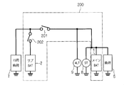
- FIG. 7 is a circuit diagram showing a configuration of a battery system in which the in-vehicle power supply device 200 supplies power not only to the general load 5 but also to the idling stop load 7.
- the in-vehicle power supply device 200 includes a main battery (indicated as “main BAT” in the drawing) 1, a sub battery (indicated as “sub BAT” in the drawing) 2, and relays 201 and 202.
- the load 5 is connected to the main battery 1 without passing through the relays 201 and 202.
- a failure for example, a ground fault, occurs on the main battery 1 side of the relay 201.
- the relays 201 and 202 are normally controlled so as to transition from the closed state to the open state in order to interrupt the overcurrent when it is detected. Therefore, when assumed as described above, an overcurrent starts to flow from the sub battery 2 via the relays 201 and 202, and the relay 202 is in an open state.
- the relay 202 is in the open state in this way, the power supply from the sub battery 2 to the idling stop load 7 is stopped. At this time, since a failure has occurred on the main battery 1 side, power is not substantially supplied to the idling stop load 7 regardless of whether the relay 201 is in a closed state or an open state.
- an object of the present invention is to provide a technology for supplying power to an external load while avoiding the occurrence of overcurrent even when either a failure on the main battery side or a failure on the sub battery side occurs. .
- Each of the in-vehicle power supply devices includes an in-vehicle main battery and an in-vehicle sub battery, a first switch and a second switch, and a main power supply path and a sub power supply path.
- the second switch is connected to the main battery via the first switch.
- the sub battery is connected to the main battery through the first switch and the second switch.
- the main power supply path bypasses the first switch and the second switch and connects the main battery to a load.
- the auxiliary power supply path connects the auxiliary battery to the load via the second switch.
- the first switch transitions from on to off when an overcurrent flows.
- the charging direction is a direction in which a current flows through the first switch when the main battery charges the sub battery.
- the in-vehicle power supply device supplies power to the outside while avoiding the occurrence of overcurrent even when either a failure on the main battery side or a failure on the sub battery side occurs.
- FIG. 10 is a circuit diagram showing an in-vehicle power supply device according to modification B. It is a circuit diagram which shows the prior art.
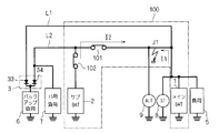
- FIG. 1 is a circuit diagram showing an in-vehicle power supply device 100 according to an embodiment and elements connected thereto.
- the in-vehicle power supply device 100 includes a main battery 1, a sub battery 2, relays 101 and 102, and circuits 401 and 402 (both expressed as “current / voltage detection” in the figure) for detecting current and voltage.
- the relays 101 and 102 are controlled by an in-vehicle ECU (electronic control unit) 403 in an open state / closed state.
- the vehicle-mounted ECU 403 causes the relays 101 and 102 to transition between the open state and the closed state when overvoltage or overcurrent is detected in the circuits 401 and 402.
- the main battery 1 and the sub battery 2 are both for vehicle use, and relays 101 and 102 are connected in series between them.
- Relay 101 is connected to main battery 1 via circuit 401
- relay 102 is connected to main battery 1 via relay 101 and circuit 401.
- the relays 101 and 102 can be grasped as switches whose closed / open states correspond to ON / OFF, respectively.
- the main battery 1 is charged from the outside of the in-vehicle power supply device 100. Specifically, the main battery 1 is connected to an on-vehicle alternator 9 and is charged by the power generation function of the alternator 9. The sub battery 2 is charged via the relays 101 and 102 by at least one of the alternator 9 and the main battery 1. For convenience of explanation to be described later, a direction in which a current flows through the relay 101 when the main battery 1 charges the sub battery 2 is referred to as a “charging direction”.
- the main battery 1 is, for example, a lead storage battery
- the secondary battery 2 is, for example, a lithium ion battery.
- Each of the main battery 1 and the sub battery 2 is a concept including a capacitor.
- an electric double layer capacitor may be employed for the sub battery 2.
- a starter 8 is connected to the main battery 1 together with a general load 5 from the outside of the in-vehicle power supply device 100.
- the load 5 is a load that is not subject to backup of the sub-battery 2, and is, for example, an in-vehicle air conditioner.
- the starter 8 is a motor that starts an engine (not shown). Since the load 5 and the starter 8 are known loads and do not have specific characteristics in the embodiment, detailed description thereof is omitted.
- the backup load 6 is a load for which power supply is desired to be maintained even when the power supply from the main battery 1 is lost, and examples include a shift-by-wire actuator and an electronically controlled braking force distribution system.
- the in-vehicle power supply device 100 further includes a main power supply path L1 and a sub power supply path L2, and supplies power to the backup load 6 through these.
- the main power supply path L1 connects the main battery 1, the load 5, and the backup load 6 in parallel with a fixed potential point (here, ground). That is, both the load 5 and the backup load 6 receive power via the main power supply path L1.
- the main power supply path L1 connects the main battery 1 and the backup load 6 without passing through the relays 101 and 102 (that is, bypassing them).
- the sub power feeding path L ⁇ b> 2 is connected to the sub battery 2 via the relay 102 and the circuit 402. Therefore, the backup load 6 can receive power not only from the main battery 1 but also from the sub battery 2.
- the diode group 3 is interposed between the backup load 6 and the main power supply path L1 and the sub power supply path L2.
- the diode group 3 prevents current from flowing between the main battery 1 and the sub battery 2 via the main power supply path L1 and the sub power supply path L2. This is because the wraparound causes deterioration of one or both of the main battery 1 and the sub battery 2.
- both the main battery 1 and the sub battery 2 supply power to the backup load 6 at a potential higher than ground.
- the cathodes of the pair of diodes 33 and 34 constituting the diode group 3 are connected in common and connected to the backup load 6.
- the anode of the diode 33 is connected to the main power supply path L1
- the anode of the diode 34 is connected to the sub power supply path L2.
- the charging direction described above is a direction from the main battery 1 toward the sub battery 2.
- the idling stop load 7 is connected to the auxiliary power supply path L2, and is connected to the auxiliary battery 2 via the relay 102 and the circuit 402. Further, it is connected to the main battery 1 via the relay 101 and the circuit 401.
- the connection relationship between the idling stop load 7 and the relays 101 and 102 and the main battery 1 and the sub battery 2 in the present embodiment is considered for the idling stop shown in FIG. 7 except for the circuits 401 and 402.
- the connection relationship between the load 7 and the relays 201 and 202 and the main battery 1 and the sub battery 2 is the same.
- the circuit 401 and the circuit 402 detect the voltage of the main battery 1 (hereinafter referred to as “main voltage”) and the voltage of the sub battery 2 (hereinafter referred to as “sub voltage”), respectively.
- main voltage the voltage of the main battery 1
- sub voltage the voltage of the sub battery 2
- the in-vehicle ECU 403 sets the open / closed state of the relays 101 and 102 as follows.
- the relays 101 and 102 are both closed and the sub-battery 2 is charged by the main battery 1 and / or the alternator 9. If the sub-voltage is high enough to determine that charging to the sub-battery 2 is excessive, the relay 101 is opened and charging to the sub-battery 2 is stopped. At this time, if the relay 102 is closed, power is supplied to the backup load 6 from the main power supply path L1 or the sub power supply path L2 depending on the magnitude relationship between the main voltage and the subvoltage.
- the closed state / open state of the relay 102 is selected according to the operation.
- such selection of the closed state / open state in the relay 102 when the secondary battery 2 is not charged in a normal state is not essential. Therefore, a detailed description of such selection is omitted.
- the circuit 401 detects the current flowing through the relay 101 (hereinafter referred to as “first current”) including the flowing direction. As will be described later, this is to know whether the direction in which the first current flows is the charging direction or the opposite direction.
- the charging direction is determined by positive / negative with respect to the ground potential of the power supplied by the main battery 1 and the sub battery 2. Therefore, if the configurations of the main battery and the sub battery 2 employed in the in-vehicle power supply device 100 are known, the charging direction is also known, and the direction in which the first current flows can be recognized from the sign of the first current.
- the charging direction is the direction from the main battery 1 to the sub battery 2 as described above.
- the first current is detected with the direction from the main battery 1 to the sub-battery 2 being positive, when the first current is positive, the direction in which the first current flows is the charging direction.
- the first current is negative, the direction in which the first current flows is opposite to the charging direction.
- the direction in which the first current flows is the charging direction when the first current is a negative value.
- the direction in which the first current flows is opposite to the charging direction.
- the charging direction is the direction from the sub battery 2 to the main battery 1.
- the direction in which the first current flows is the charging direction when the first current is a negative value.
- the direction in which the first current flows is opposite to the charging direction.
- the first current is detected with the direction from the sub battery 2 to the main battery 1 being positive, the direction in which the first current flows is the charging direction when the first current is a positive value.
- the first current is negative, the direction in which the first current flows is opposite to the charging direction.
- the anodes of the diodes 33 and 34 are commonly connected to the backup load 6 in the diode group 3, and the cathodes of the diodes 33 and 34 are connected to the main power supply path L1 and the sub power supply path L2, respectively.
- the in-vehicle ECU 403 determines that the first current (absolute value thereof) is an overcurrent, the in-vehicle ECU 403 opens the relay 101 even when the secondary battery 2 is being charged.
- the circuit 402 detects a current flowing through the relay 102 (hereinafter referred to as “second current”).
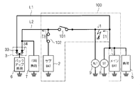
- FIG. 2 is a circuit diagram showing a situation in which the ground fault J1 occurs on the main battery 1 side than the relay 101 (more precisely, than the circuit 401) when the relays 101 and 102 are in the closed state. Due to the ground fault J1, not only the current I1 flows from the main battery 1 to the ground, but also the current I2 flows from the sub battery 2 to the ground via the relays 101 and 102. The same applies when a ground fault occurs in the main power supply path L1.
- the current I2 is a ground fault current and flows not only as the second current but also as the first current. Therefore, the circuits 401 and 402 detect both the first current and the second current as overcurrent.
- both the main battery 1 and the sub battery 2 are short-circuited by the ground fault J1, and power cannot be supplied from either the main power supply path L1 or the sub power supply path L2.
- the relays 101 and 102 are all opened, power supply from the auxiliary power supply path L2 is not continued.
- the current I2 flows as the first current in the direction opposite to the charging direction.
- the relay 102 when an overcurrent flowing in the direction opposite to the charging direction is detected as the first current, it is determined that no ground fault has occurred in the auxiliary power supply path L2, and the relay 102 is in the closed state.
- the relay 101 transitions from the closed state to the open state.
- the secondary battery 2 is disconnected from the ground fault J1, and the current I2, which is a ground fault current, does not flow.
- the sub battery 2 supplies the current I3 to the sub power feeding path L2. Since the current I3 is not a ground fault current, the circuit 402 does not determine that the second current is an overcurrent, and therefore the relay 102 remains closed.
- the secondary battery 2 functions as a backup power source for the backup load 6.
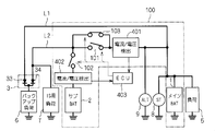
- FIG. 4 is a circuit showing a situation where a ground fault J2 occurs on the opposite side of the main battery 1 and the sub battery 2 from the relays 101 and 102, that is, in the sub power feeding path L2, when the relays 101 and 102 are in the closed state.
- a current I4 flows from the main battery 1 via the relay 101
- a current I5 flows from the sub battery 2 via the relay 102 to the ground.
- Currents I4 and I5 are ground fault currents, which respectively flow as a first current and a second current. Therefore, the circuits 401 and 402 detect both the first current and the second current as overcurrent.
- the current I4 flows in the charging direction as the first current.
- an overcurrent flowing in the charging direction is detected as the first current, it is determined that a ground fault has occurred in the sub-feeding path L2, and both of the relays 101 and 102 are closed. Transition to the open state.
- the main battery 1 and the sub battery 2 are isolated from the ground fault J2 as shown in FIG. Since the main power supply path L1 bypasses both of the relays 101 and 102 and is connected to the backup load 6, the current I6 flows from the main battery 1 through the main power supply path L1.
- the main battery 1 functions as a backup power source for the backup load 6.
- the main battery 1 functions as a backup power source for the backup load 6.
- the relay 101 is not transitioned to the closed state even if the overcurrent is not detected in the first current. This is to prevent the current I2 or the current I4 from flowing again as a ground fault current.
- the in-vehicle ECU 403 includes, for example, a microcomputer and a storage device.
- the microcomputer executes each processing step (in other words, a procedure) described in the program.
- the storage device can be composed of one or more of various storage devices such as ROM (Read Only Memory), RAM (Random Access Memory), and rewritable nonvolatile memory (EPROM (Erasable Programmable ROM), etc.).
- the storage device stores various information, data, and the like, stores a program executed by the microcomputer, and provides a work area for executing the program. It can be understood that the microcomputer functions as various means corresponding to each processing step described in the program, or can realize that various functions corresponding to each processing step are realized. Further, the in-vehicle ECU 403 is not limited to this, and various procedures executed by the in-vehicle ECU 403 or various means or various functions implemented may be realized by hardware.
- a circuit for controlling the relays 101 and 102 may be incorporated in either of the relays 101 and 102.
- the relay 102 when the overcurrent starts to flow through the relay 102, the relay 102 is maintained in the closed state for a predetermined period. When the overcurrent does not flow through the relay 101 within the predetermined period, the relay 102 changes from the closed state to the open state. Transition.
- the relay 103 should be in the open state with the transition from the closed state to the open state of the relay 101 so as not to hinder the effect of the relay 101 being in the open state in the operations (i) and (ii). Is desirable.
Landscapes
- Engineering & Computer Science (AREA)
- Power Engineering (AREA)
- Mechanical Engineering (AREA)
- Charge And Discharge Circuits For Batteries Or The Like (AREA)
Priority Applications (2)
| Application Number | Priority Date | Filing Date | Title |
|---|---|---|---|
| CN201680054346.7A CN108028545A (zh) | 2015-09-25 | 2016-09-21 | 车载用电源装置及其控制方法 |
| US15/762,779 US20190071039A1 (en) | 2015-09-25 | 2016-09-21 | In-vehicle power supply device and control method for the same |
Applications Claiming Priority (2)
| Application Number | Priority Date | Filing Date | Title |
|---|---|---|---|
| JP2015-187699 | 2015-09-25 | ||
| JP2015187699A JP2017061240A (ja) | 2015-09-25 | 2015-09-25 | 車載用電源装置及びその制御方法 |
Publications (1)
| Publication Number | Publication Date |
|---|---|
| WO2017051812A1 true WO2017051812A1 (ja) | 2017-03-30 |
Family
ID=58386842
Family Applications (1)
| Application Number | Title | Priority Date | Filing Date |
|---|---|---|---|
| PCT/JP2016/077762 Ceased WO2017051812A1 (ja) | 2015-09-25 | 2016-09-21 | 車載用電源装置及びその制御方法 |
Country Status (4)
| Country | Link |
|---|---|
| US (1) | US20190071039A1 (enExample) |
| JP (1) | JP2017061240A (enExample) |
| CN (1) | CN108028545A (enExample) |
| WO (1) | WO2017051812A1 (enExample) |
Cited By (1)
| Publication number | Priority date | Publication date | Assignee | Title |
|---|---|---|---|---|
| WO2022085673A1 (ja) * | 2020-10-23 | 2022-04-28 | 株式会社アイシン | シフト装置および車両用電子制御ユニット |
Families Citing this family (12)
| Publication number | Priority date | Publication date | Assignee | Title |
|---|---|---|---|---|
| JP6540565B2 (ja) * | 2016-03-16 | 2019-07-10 | 株式会社オートネットワーク技術研究所 | 車両用電源供給システム、車両用駆動システム |
| JP6651941B2 (ja) * | 2016-03-30 | 2020-02-19 | 株式会社オートネットワーク技術研究所 | 車載電源用のスイッチ装置および制御装置 |
| KR101932279B1 (ko) | 2018-03-19 | 2019-01-02 | 주식회사 경신 | 차량 전원 제어 장치 및 방법 |
| JP7108962B2 (ja) * | 2018-12-03 | 2022-07-29 | 株式会社オートネットワーク技術研究所 | 車載用のバックアップ電源制御装置及び車載用のバックアップ電源装置 |
| JP7017139B2 (ja) * | 2018-12-26 | 2022-02-08 | 株式会社デンソー | 通電制御装置及び電源システム |
| DE102019125067A1 (de) | 2019-09-18 | 2021-03-18 | Ford Global Technologies, Llc | Verfahren zum Betrieb eines Bordnetzes eines Kraftfahrzeugs |
| WO2021245748A1 (ja) * | 2020-06-01 | 2021-12-09 | リバーフィールド株式会社 | 手術支援装置 |
| JP7563994B2 (ja) * | 2021-01-13 | 2024-10-08 | 株式会社デンソーテン | 車載電源装置および車載電源制御方法 |
| JP7565803B2 (ja) * | 2021-01-13 | 2024-10-11 | 株式会社デンソーテン | 車載電源装置および車載電源制御方法 |
| US12040639B2 (en) | 2021-02-16 | 2024-07-16 | Denso Ten Limited | Power supply device and control method |
| JP7536694B2 (ja) | 2021-03-19 | 2024-08-20 | 株式会社デンソーテン | 車載電源装置および車載電源制御方法 |
| JP7651900B2 (ja) * | 2021-03-25 | 2025-03-27 | 株式会社オートネットワーク技術研究所 | 異常検出装置、及び異常検出方法 |
Citations (4)
| Publication number | Priority date | Publication date | Assignee | Title |
|---|---|---|---|---|
| JP2010088180A (ja) * | 2008-09-30 | 2010-04-15 | Panasonic Corp | 蓄電装置 |
| JP2012130108A (ja) * | 2010-12-13 | 2012-07-05 | Denso Corp | 電源装置 |
| JP2015076959A (ja) * | 2013-10-08 | 2015-04-20 | 株式会社オートネットワーク技術研究所 | 電源システム |
| JP2015154618A (ja) * | 2014-02-14 | 2015-08-24 | 株式会社デンソー | 電池ユニット |
Family Cites Families (4)
| Publication number | Priority date | Publication date | Assignee | Title |
|---|---|---|---|---|
| DE112009002169A5 (de) * | 2008-09-08 | 2012-03-08 | Autonetworks Technologies, Ltd. | Energieversorgungsvorrichtung |
| CN102811887B (zh) * | 2010-03-29 | 2015-12-02 | 松下知识产权经营株式会社 | 车辆用电源装置 |
| JP5396446B2 (ja) * | 2011-08-30 | 2014-01-22 | 日立オートモティブシステムズ株式会社 | 車載用電源装置 |
| CN104057901B (zh) * | 2014-06-27 | 2016-04-27 | 深圳市金能弘盛能源科技有限公司 | 一种汽车用超级电容模组电源管理系统 |
-
2015
- 2015-09-25 JP JP2015187699A patent/JP2017061240A/ja active Pending
-
2016
- 2016-09-21 WO PCT/JP2016/077762 patent/WO2017051812A1/ja not_active Ceased
- 2016-09-21 US US15/762,779 patent/US20190071039A1/en not_active Abandoned
- 2016-09-21 CN CN201680054346.7A patent/CN108028545A/zh active Pending
Patent Citations (4)
| Publication number | Priority date | Publication date | Assignee | Title |
|---|---|---|---|---|
| JP2010088180A (ja) * | 2008-09-30 | 2010-04-15 | Panasonic Corp | 蓄電装置 |
| JP2012130108A (ja) * | 2010-12-13 | 2012-07-05 | Denso Corp | 電源装置 |
| JP2015076959A (ja) * | 2013-10-08 | 2015-04-20 | 株式会社オートネットワーク技術研究所 | 電源システム |
| JP2015154618A (ja) * | 2014-02-14 | 2015-08-24 | 株式会社デンソー | 電池ユニット |
Cited By (4)
| Publication number | Priority date | Publication date | Assignee | Title |
|---|---|---|---|---|
| WO2022085673A1 (ja) * | 2020-10-23 | 2022-04-28 | 株式会社アイシン | シフト装置および車両用電子制御ユニット |
| JPWO2022085673A1 (enExample) * | 2020-10-23 | 2022-04-28 | ||
| JP7380909B2 (ja) | 2020-10-23 | 2023-11-15 | 株式会社アイシン | シフト装置および車両用電子制御ユニット |
| US12247657B2 (en) | 2020-10-23 | 2025-03-11 | Aisin Corporation | Shift device and vehicle electronic control unit |
Also Published As
| Publication number | Publication date |
|---|---|
| CN108028545A (zh) | 2018-05-11 |
| JP2017061240A (ja) | 2017-03-30 |
| US20190071039A1 (en) | 2019-03-07 |
Similar Documents
| Publication | Publication Date | Title |
|---|---|---|
| WO2017051812A1 (ja) | 車載用電源装置及びその制御方法 | |
| JP6398931B2 (ja) | 車載用電源装置及びその制御方法 | |
| US10992165B2 (en) | Redundant power supply system | |
| CN108602478B (zh) | 车载电源用的开关装置及车载用电源装置 | |
| US10279761B2 (en) | Vehicle power-supply device | |
| US10399518B2 (en) | Relay device and power supply device | |
| US10549705B2 (en) | Switch device for on-board power supply and on-board power supply device | |
| JP2018196252A (ja) | 電力分配システム | |
| JP6627732B2 (ja) | 電源回路装置 | |
| WO2017169817A1 (ja) | 車載電源用のスイッチ装置および制御装置 | |
| JP6690396B2 (ja) | リレー装置 | |
| WO2017159485A1 (ja) | 車両用電源供給システム、車両用駆動システム | |
| JP6460875B2 (ja) | バッテリシステム制御装置 | |
| JP6750558B2 (ja) | 電源ボックス | |
| WO2018047636A1 (ja) | 車載用のバックアップ装置 | |
| JP2019195249A (ja) | 車両用電源システム | |
| JP6903951B2 (ja) | 電源システム | |
| JP6176186B2 (ja) | 自動車の電源装置 | |
| CN107921917A (zh) | 车载用电源装置 | |
| WO2017183512A1 (ja) | 車載電源用のスイッチ装置および車載用電源システム | |
| JP7107159B2 (ja) | 車両用バックアップ電源装置 | |
| JP2019135819A (ja) | パワー半導体デバイス、及びそのパワー半導体デバイスを備える車両用電源供給システム | |
| WO2020189571A1 (ja) | 電源装置 | |
| JP2015221594A (ja) | 自動車の電源装置 | |
| JP7565803B2 (ja) | 車載電源装置および車載電源制御方法 |
Legal Events
| Date | Code | Title | Description |
|---|---|---|---|
| 121 | Ep: the epo has been informed by wipo that ep was designated in this application |
Ref document number: 16848600 Country of ref document: EP Kind code of ref document: A1 |
|
| NENP | Non-entry into the national phase |
Ref country code: DE |
|
| 122 | Ep: pct application non-entry in european phase |
Ref document number: 16848600 Country of ref document: EP Kind code of ref document: A1 |