WO2017047657A1 - バッファ制御装置、通信ノード、及び中継装置 - Google Patents
バッファ制御装置、通信ノード、及び中継装置 Download PDFInfo
- Publication number
- WO2017047657A1 WO2017047657A1 PCT/JP2016/077149 JP2016077149W WO2017047657A1 WO 2017047657 A1 WO2017047657 A1 WO 2017047657A1 JP 2016077149 W JP2016077149 W JP 2016077149W WO 2017047657 A1 WO2017047657 A1 WO 2017047657A1
- Authority
- WO
- WIPO (PCT)
- Prior art keywords
- message
- unit
- control device
- input
- same
- Prior art date
- Legal status (The legal status is an assumption and is not a legal conclusion. Google has not performed a legal analysis and makes no representation as to the accuracy of the status listed.)
- Ceased
Links
Images



Classifications
-
- H—ELECTRICITY
- H04—ELECTRIC COMMUNICATION TECHNIQUE
- H04L—TRANSMISSION OF DIGITAL INFORMATION, e.g. TELEGRAPHIC COMMUNICATION
- H04L47/00—Traffic control in data switching networks
- H04L47/50—Queue scheduling
- H04L47/62—Queue scheduling characterised by scheduling criteria
- H04L47/6245—Modifications to standard FIFO or LIFO
-
- H—ELECTRICITY
- H04—ELECTRIC COMMUNICATION TECHNIQUE
- H04L—TRANSMISSION OF DIGITAL INFORMATION, e.g. TELEGRAPHIC COMMUNICATION
- H04L12/00—Data switching networks
- H04L12/28—Data switching networks characterised by path configuration, e.g. LAN [Local Area Networks] or WAN [Wide Area Networks]
- H04L12/46—Interconnection of networks
- H04L12/4604—LAN interconnection over a backbone network, e.g. Internet, Frame Relay
- H04L12/462—LAN interconnection over a bridge based backbone
- H04L12/4625—Single bridge functionality, e.g. connection of two networks over a single bridge
-
- H—ELECTRICITY
- H04—ELECTRIC COMMUNICATION TECHNIQUE
- H04L—TRANSMISSION OF DIGITAL INFORMATION, e.g. TELEGRAPHIC COMMUNICATION
- H04L12/00—Data switching networks
- H04L12/28—Data switching networks characterised by path configuration, e.g. LAN [Local Area Networks] or WAN [Wide Area Networks]
-
- H—ELECTRICITY
- H04—ELECTRIC COMMUNICATION TECHNIQUE
- H04L—TRANSMISSION OF DIGITAL INFORMATION, e.g. TELEGRAPHIC COMMUNICATION
- H04L67/00—Network arrangements or protocols for supporting network services or applications
- H04L67/01—Protocols
- H04L67/12—Protocols specially adapted for proprietary or special-purpose networking environments, e.g. medical networks, sensor networks, networks in vehicles or remote metering networks
Definitions
- This disclosure relates to a buffer control device, a communication node, and a relay device.
- the communication device includes a buffer for temporarily storing a message to be transmitted or a received message.
- a buffer for temporarily storing a message to be transmitted or a received message.
- Another method is to provide a separate buffer for each ID included in a message (see Patent Document 1).
- a buffer control device receives an input unit that receives an input of a message including an ID and data, a buffer unit that stores a message, and a message stored in the buffer unit by the input unit.
- the same ID determination unit that determines whether or not the same ID as the ID included in the message exists, and if the same ID exists, at least the data of the message including the same ID is received by the input unit If the same ID does not exist with the overwrite unit that overwrites the data contained in the message, the storage unit that stores the message received by the input unit in the buffer unit, and the message that is stored first by the storage unit From the buffer unit and output And an output unit that.
- the buffer control device includes the same ID when the message stored in the buffer unit includes the same ID as the ID included in the message received by the input unit. At least the data stored in the message is overwritten with the data included in the message received by the input unit.
- the buffer control device does not store all of the large number of messages in the buffer unit. As a result, it can be suppressed that a message including an ID different from the large number of messages is lost from the buffer unit.
- the buffer control device can update the data included in the message stored in the buffer unit to the latest one. Furthermore, the buffer control device according to one aspect of the present disclosure is not necessarily provided with a separate buffer unit for each ID. As a result, the memory area used for the buffer unit can be reduced.
- a buffer control device includes an input unit that receives an input of a message including an ID and data, a buffer unit that stores the message, and an input unit that accepts the message stored in the buffer unit. Whether the ID included in the message received by the input unit and the same ID determination unit that determines whether or not the same ID as the ID included in the received message corresponds to a preset overwritable ID If the same ID exists and the ID included in the message received by the input unit corresponds to the overwritable ID, at least the data in the message including the same ID is determined.
- a storage unit that stores a message received by the input unit in the buffer unit, and an ID that is included in the message received by the input unit does not correspond to an overwritable ID.
- An output unit that extracts from the buffer unit and outputs the message that is first in the order stored by the unit.
- the message stored in the buffer unit includes the same ID as the ID included in the message received by the input unit, and the message received by the input unit When the included ID corresponds to an overwritable ID, at least data among messages stored in the buffer unit including the same ID is overwritten with data included in the message received by the input unit.
- the buffer control device is configured such that, for example, even when a large number of messages including the same ID are input to the input unit, Not all messages are stored in the buffer unit. As a result, it can be suppressed that a message including an ID different from the large number of messages is lost from the buffer unit.
- the buffer control device can update the data included in the message stored in the buffer unit to the latest one. Furthermore, the buffer control device according to another aspect of the present disclosure is not necessarily provided with a separate buffer unit for each ID. As a result, the memory area used for the buffer unit can be reduced.
- the buffer control device overwrites an ID that is the same as the ID included in the message received by the input unit in the message stored in the buffer unit. If it does not correspond to the possible ID, data is not overwritten, and the input message is stored in the buffer unit. As a result, for a message including an ID that does not correspond to the overwritable ID, a plurality of messages including the same ID can be stored in the buffer unit.
- FIG. 4A is an explanatory diagram showing the buffer unit and the input message before the data is overwritten
- FIG. 4B is an explanatory diagram showing the buffer unit at the time after the data is overwritten
- FIG. 5A is an explanatory diagram illustrating a buffer unit at a time before storing an input message
- FIG. 5B is an explanatory diagram illustrating a buffer unit at a time after storing the input message.
- It is a block diagram showing the structure of the buffer control apparatus for reception. It is a flowchart showing the process which the buffer control apparatus for reception performs.
- the communication system 1 is an in-vehicle communication system mounted on a vehicle.
- the communication system 1 is a multiple communication system.
- the communication system 1 includes a plurality of communication systems 3 and 5 and a relay device 7.
- a plurality of ECUs 11 are connected to the multiplex communication line 9.
- the ECU 11 corresponds to a communication node.
- the communication system 1 transmits and receives messages using a predetermined protocol.
- the message includes at least an ID and data.
- the ID represents the type of data included in the message.
- Each ECU 11 includes an application 13 having a function of creating a message.
- the ECU 11 transmits a message created by its own application 13 to another ECU 11. Further, the ECU 11 receives a message transmitted from another ECU 11 and transmits it to its own application 13.
- the application 13 performs a predetermined process using the transmitted message.
- the relay device 7 is connected to each of the communication systems 3 and 5.
- the relay device 7 relays a message when the ECU 11 that is the transmission source of the message and the ECU 11 that is the transmission destination belong to different communication systems.
- the relay device 7 includes a relay control unit 15 and a routing map 17.
- the relay control unit 15 executes processing related to message relay.
- the routing map 17 stores the ID included in the message and the transmission destination of the message in association with each other.
- the relay control unit 15 When the relay control unit 15 receives a message from one communication system, the relay control unit 15 reads the ID included in the message and refers to the routing map 17 to determine the ECU 11 that is the transmission destination of the message. Next, the relay control unit 15 transmits the message to the communication system to which the ECU 11 as the transmission destination belongs.
- the ECU 11 includes a reception buffer control device 19 that temporarily stores a message received from another ECU 11 and a transmission buffer control device 21 that temporarily stores a message to be transmitted to the other ECU 11.
- the relay device 7 includes a reception buffer control device 23 and a transmission buffer control device 25 for each communication system.
- the reception buffer control device 23 temporarily stores a message received from the corresponding communication system, and outputs the stored message to the relay control unit 15. Further, the transmission buffer control device 25 temporarily stores the message input from the relay control unit 15 and outputs the stored message to the corresponding communication system.
- the reception buffer control device 19 includes a communication IC that forms an interface with the multiplex communication line 9 and a control microcomputer.
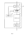
- the reception buffer controller 19 functionally includes an input unit 27, a storage control unit 29, an ID search unit 31, a buffer unit 33, and an output unit 35. The function of each unit will be described later.
- each unit is realized by a program stored in a ROM provided in the microcomputer and executed on a CPU provided in the microcomputer.
- the buffer unit 33 is allocated on a RAM or a registry included in the microcomputer.
- a nonvolatile memory other than the ROM provided in the microcomputer, a nonvolatile memory outside the microcomputer provided in the ECU 11, and a RAM may be used.
- the ID search unit 31 corresponds to the same ID determination unit.
- the storage control unit 29 corresponds to an overwrite unit and a storage unit. 3. Processing Performed by Reception Buffer Control Device 19 The processing performed by reception buffer control device 19 will be described with reference to FIGS. 3, 4A, 4B, 5A, and 5B. Here, the processing of the reception buffer control device 19 provided in one ECU 11 (hereinafter referred to as its own ECU 11) will be described. Hereinafter, the ECU 11 other than its own ECU 11 may be referred to as another ECU 11.
- the input unit 27 receives a message input.
- the message input to the input unit 27 is hereinafter referred to as an input message.
- the input message is transmitted by another ECU 11 with its own ECU 11 as a transmission destination.
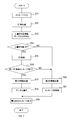
- step 2 the input unit 27 transmits the ID included in the input message (hereinafter referred to as input message ID) to the ID search unit 31. Further, the input unit 27 transmits the input message ID and data included in the input message (hereinafter referred to as input message data) to the storage control unit 29.
- input message ID the ID included in the input message
- input message data the input message data included in the input message
- step 3 the ID search unit 31 searches the message stored in the buffer unit 33 (hereinafter referred to as a stored message) for the same ID as the input message ID transmitted in step 2.
- step 4 based on the result of the search in step 3, the ID search unit 31 determines whether or not the same ID as the input message ID exists in the stored message. If it is determined that the same ID as the input message ID exists in the stored message, the process proceeds to step 5, and if it is determined that such an ID does not exist, the process proceeds to step 8.
- step 5 the ID retrieval unit 31 transmits first information including the following contents (1a) to (1c) to the storage control unit 29. (1a) Input message ID.
- step 6 the storage control unit 29 specifies the storage location of the same ID storage message using the information (1c). Next, the storage control unit 29 overwrites the data in the same ID storage message with the input message data.
- stored messages M1, M2,... Mi,. n is a natural number, and i is an arbitrary natural number from 1 to n.
- the order in which the stored messages are stored in the buffer unit 33 (hereinafter referred to as storage order) is M1 ⁇ M2 ⁇ M3 ⁇ .
- the storage order is the order in which the input messages are stored in the process of step 9 described later.
- the buffer unit 33 holds the storage order.
- the same ID as the input message ID exists in the stored message Mi.
- the input message is expressed as EM
- the input message ID is expressed as EM-ID.
- the content of the input message ID is “333”.
- the stored message Mi is the same ID stored message.
- an affirmative determination is made in step 4, and in step 6, as shown in FIG. 4B, the data in the stored message Mi is overwritten with the input message data.
- the number of stored messages does not change even if overwriting is performed as described above. Further, the storage order of the stored messages M1, M2,. For example, even when the data of the stored message Mi is overwritten as described above, the storage order of the stored message Mi remains i-th.
- step 7 the output unit 35 extracts the stored message having the earliest storage order and transmits it to the application 13 in its own ECU 11.
- the retrieved stored message is erased from the buffer unit 33.
- step 4 the process proceeds to step 8 where the ID search unit 31 transmits the second information including the following contents (2a) to (2b) to the storage control unit 29.
- step 9 the storage control unit 29 stores the input message in the buffer unit 33.
- the storage order of the input messages newly stored in this step is later than any stored messages that have already been stored. By storing the input message, the number of stored messages increases by one.
- the same ID as the input message ID does not exist in the stored messages M1 to Mn.
- the input message is expressed as EM
- the input message ID is expressed as EM-ID.
- the content of the input message ID is “123”.
- step 4 a negative determination is made in step 4, and in step 9, the input message is newly stored in the buffer unit 33 as shown in FIG. 5B.
- the storage order of the newly stored input message is later than any of the stored messages M1, M2,... Mi,... Mn, and is (n + 1) th in the case shown in FIG. .
- the transmission buffer control device 21, the reception buffer control device 23, and the transmission buffer control device 25 also execute the same processing as the reception buffer control device 19.
- the input unit 27 of the transmission buffer control device 21 receives an input of a message created by the application 13 in its own ECU 11.
- the output unit 35 of the transmission buffer control device 21 outputs the message taken out from the buffer unit 33 to the other ECU 11.
- the input unit 27 of the reception buffer control device 23 receives a message input from a communication system corresponding to the reception buffer control device 23.
- the output unit 35 of the reception buffer control device 23 outputs the message extracted from the buffer unit 33 toward the relay control unit 15.
- the input unit 27 of the transmission buffer control device 25 receives a message input from the relay control unit 15. Further, the output unit 35 of the transmission buffer control device 25 outputs the message extracted from the buffer unit 33 to the communication system corresponding to the transmission buffer control device 25.
- Effects of receiving buffer control device 19 The receiving buffer control device 19 of the present embodiment has the following effects.
- the transmission buffer control device 21, the reception buffer control device 23, and the transmission buffer control device 25 also have the same effect.
- the reception buffer controller 19 does not store the input message in the buffer unit 33 in the process of step 9 and does not increase the number of stored messages.
- the reception buffer control device 19 can suppress the loss of stored messages including different IDs even when a large number of input messages including the same ID are input to the input unit 27.
- the reception buffer control device 19 When the same ID storage message exists, the reception buffer control device 19 overwrites the data portion of the same ID storage message with the input message data. As a result, the data in the same ID storage message can be updated to the latest one.
- the reception buffer control device 19 is not necessarily provided with a separate buffer unit for each ID. As a result, the memory area used as the buffer unit can be reduced.
- the reception buffer control device 19 has the configuration shown in FIG. Note that the transmission buffer control device 21, the reception buffer control device 23, and the transmission buffer control device 25 have the same configuration as the reception buffer control device 19.
- the reception buffer control device 19 includes an overwrite permission / inhibition information table 37 in addition to the input unit 27, the storage control unit 29, the ID search unit 31, the buffer unit 33, and the output unit 35.
- the overwrite permission / inhibition information table 37 is a table in which information that can specify whether or not any specified ID is an overwriteable ID is recorded. As a specific example of the overwrite permission / inhibition information table 37, there is one in which whether or not all IDs are overwritable IDs is individually recorded.
- the overwrite permission / inhibition information table 37 there is a record in which only overwrite possible IDs are recorded among all IDs. In this case, if an arbitrarily designated ID is recorded in the overwrite permission / inhibition information table 37, the ID is an overwriteable ID, and if not, it is not an overwriteable ID.
- the overwrite permission / inhibition information table 37 there is a record in which only IDs that are not overwriteable IDs are recorded. In this case, if an arbitrarily designated ID is not recorded in the overwrite permission / inhibition information table 37, the ID is an overwriteable ID, and if recorded, it is not an overwriteable ID.
- the overwrite permission / inhibition information table 37 As another specific example of the overwrite permission / inhibition information table 37, a part of ID information is registered instead of a specific ID, and only IDs belonging to ID groups that meet the conditions are recorded. There is. In this case, if any specified ID belongs to the ID group recorded in the overwrite permission / inhibition information table 37, the ID is an overwriteable ID. Otherwise, the ID is not an overwriteable ID. Become.
- the overwrite permission / inhibition information table 37 As another specific example of the overwrite permission / inhibition information table 37, a part of ID information is registered instead of a specific ID, and only IDs belonging to ID groups that meet the conditions are not recorded. There is. In this case, if any specified ID does not belong to the ID group recorded in the overwrite permission / inhibition information table 37, the ID is an overwriteable ID, and if it belongs, it is not an overwriteable ID. Become.
- ID search unit 31 corresponds to the same ID determination unit.
- ID search unit 31 and the overwrite permission / inhibition information table 37 correspond to an overwrite possible ID determination unit.
- the storage control unit 29 corresponds to an overwrite unit and a storage unit.
- step 13 the ID search unit 31 compares the input message ID transmitted in step 12 with the contents of the overwrite permission / inhibition information table 37. In step 14, based on the comparison result in step 13, the ID search unit 31 determines whether or not the input message ID corresponds to an overwritable ID. When it corresponds to the overwritable ID, the process proceeds to step 15, and when it does not correspond to the overwritable ID, the process proceeds to step 20.
- Steps 15 to 21 are the same as steps 3 to 9 of the first embodiment.
- the transmission buffer control device 21, the reception buffer control device 23, and the transmission buffer control device 25 also execute the same processing as the reception buffer control device 19.
- the receiving buffer control device 19 of the present embodiment has the following effects in addition to the effect (1C) of the first embodiment.
- the transmission buffer control device 21, the reception buffer control device 23, and the transmission buffer control device 25 also have the same effect.
- the reception buffer control device 19 sends the input message to the above-mentioned step 9 although it has the same simple structure as the FIFO buffer. In this process, the data is not stored in the buffer unit 33, and the number of stored messages is not increased.
- the reception buffer control device 19 can suppress the loss of stored messages including different IDs even when a large number of input messages including the same ID are input to the input unit 27.
- the reception buffer control device 19 sets the same ID storage message in the same configuration as the FIFO buffer. The data part is overwritten with the input message data. As a result, the data in the same ID storage message can be updated to the latest one.
- a plurality of messages including the same ID can be stored in the buffer unit 33 for a message including an ID that does not correspond to the overwriteable ID.
- the message structure can be set as appropriate. For example, other areas may be provided in addition to the ID and data.
- the range to be overwritten in steps 6 and 18 can be set as appropriate. For example, a portion other than data (for example, ID) in the stored message may be overwritten. Further, all stored messages may be overwritten with the input message.
- the processes in steps 7 and 19 may be performed at a timing independent of the message input.
- the processes in steps 7 and 19 may be performed at a predetermined cycle.
- the reception buffer control device 19 and the transmission buffer control device 21 may be provided in another communication node (for example, a host computer, a terminal device, a communication device, an exchange, or the like).
- the communication system 1 may be a communication system provided in a place other than a vehicle (for example, infrastructure, house, office, etc.).
- (6) (1b) and (1c) constituting the first information may be combined into one data.
- the first information may not include the content of (1a).
- the second information may not include the content of (2a). Even in this case, the storage control unit 29 can perform a predetermined process using the ID acquired from the input unit 27.
- a part or all of the functions executed by the reception buffer control device 19, the transmission buffer control device 21, the reception buffer control device 23, and the transmission buffer control device 25 are performed by one or a plurality of ICs. You may comprise in hardware.
- a buffer control device In addition to the above-described reception buffer control device 19, transmission buffer control device 21, reception buffer control device 23, and transmission buffer control device 25 (hereinafter collectively referred to as a buffer control device), a buffer control device
- the present disclosure can also be realized in various forms, such as a system including a program, a program for causing a computer to function as the buffer control device, a medium on which the program is recorded, and a message storage method.
Landscapes
- Engineering & Computer Science (AREA)
- Computer Networks & Wireless Communication (AREA)
- Signal Processing (AREA)
- Small-Scale Networks (AREA)
- Data Exchanges In Wide-Area Networks (AREA)
Abstract
Description
本開示の一局面によるバッファ制御装置は、ID及びデータを含むメッセージの入力を受け付ける入力ユニットと、メッセージを格納するバッファユニットと、バッファユニットに格納されているメッセージの中に、入力ユニットで受け付けたメッセージに含まれるIDと同一のIDが存在するか否かを判断する同一ID判断ユニットと、同一のIDが存在する場合、その同一のIDを含むメッセージのうち、少なくともデータを、入力ユニットで受け付けたメッセージに含まれるデータで上書きする上書きユニットと、同一のIDが存在しない場合、入力ユニットで受け付けたメッセージをバッファユニットに格納する格納ユニットと、格納ユニットにより格納された順番が最も先であるメッセージをバッファユニットから取り出し、出力する出力ユニットとを備える。
<第1の実施形態>
1.通信システム1の構成
通信システム1の構成を図1に基づき説明する。通信システム1は、車両に搭載される車載通信システムである。また、通信システム1は、多重通信システムである。通信システム1は、複数の通信系3、5と、中継装置7とを備える。通信系3、5は、それぞれ、多重通信線9に、複数のECU11が接続したものである。ECU11は通信ノードに対応する。
受信用バッファ制御装置19の構成を図2に基づき説明する。なお、送信用バッファ制御装置21、受信用バッファ制御装置23、及び送信用バッファ制御装置25も、受信用バッファ制御装置19と同様の構成を有する。
3.受信用バッファ制御装置19が実行する処理
受信用バッファ制御装置19が実行する処理を図3、図4A、図4B、図5A、及び図5Bに基づき説明する。なお、ここでは、一つのECU11(以下では、自己のECU11とする)が備える受信用バッファ制御装置19の処理を説明する。自己のECU11以外のECU11を、以下では、他のECU11と呼ぶことがある。
(1a)入力メッセージID。
(1c)格納メッセージのうち、入力メッセージIDと同一のIDを含むメッセージ(以下では同一ID格納メッセージとする)の、バッファユニット33における格納場所。
(2b)格納メッセージの中に入力メッセージIDと同一のIDが存在しないこと。
ステップ9では、格納制御ユニット29が、入力メッセージをバッファユニット33に格納する。本ステップで新たに格納された入力メッセージの格納順序は、既に格納されていた格納メッセージのいずれよりも後である。入力メッセージを格納することで、格納メッセージの数は1だけ増加する。
本実施形態の受信用バッファ制御装置19は以下の効果を奏する。送信用バッファ制御装置21、受信用バッファ制御装置23、及び送信用バッファ制御装置25も同様の効果を奏する。
<第2の実施形態>
1.第1の実施形態との構成における相違点
第2の実施形態は、基本的な構成は第1の実施形態と同様であるため、共通する構成については説明を省略し、相違点を中心に説明する。第1の実施形態と同じ符号は、同一の構成を示すものであって、先行する説明を参照する。
受信用バッファ制御装置19が実行する処理を図7に基づき説明する。図7のステップ11、12の処理は、前記第1の実施形態におけるステップ1、2の処理と同様である。
ステップ14では、前記ステップ13での対比結果に基づき、入力メッセージIDが上書き可能IDに該当するか否かをID検索ユニット31が判断する。上書き可能IDに該当する場合はステップ15に進み、上書き可能IDに該当しない場合はステップ20に進む。
送信用バッファ制御装置21、受信用バッファ制御装置23、及び送信用バッファ制御装置25も、受信用バッファ制御装置19と同様の処理を実行する。
本実施形態の受信用バッファ制御装置19は、前記第1の実施形態の効果(1C)に加え、以下の効果を奏する。送信用バッファ制御装置21、受信用バッファ制御装置23、及び送信用バッファ制御装置25も同様の効果を奏する。
<その他の実施形態>
以上、本開示の実施形態について説明したが、本開示は上記実施形態に限定されることなく、種々の形態を採り得る。
(2)前記ステップ6、18で上書きする範囲は適宜設定できる。例えば、格納メッセージのうち、データ以外の部分(例えばID)も上書きしてもよい。また、格納メッセージの全てを入力メッセージで上書きしてもよい。
(4)ECU11に代えて、他の通信ノード(例えば、ホストコンピュータ、端末装置、通信機器、交換機等)に、受信用バッファ制御装置19及び送信用バッファ制御装置21を設けてもよい。
(6)前記第1の情報を構成する(1b)、(1c)は、一つのデータにまとめてもよい。
Claims (6)
- ID及びデータを含むメッセージの入力を受け付ける入力ユニット(25)と、
前記メッセージを格納するバッファユニット(33)と、
前記バッファユニットに格納されている前記メッセージの中に、前記入力ユニットで受け付けた前記メッセージに含まれるIDと同一のIDが存在するか否かを判断する同一ID判断ユニット(31)と、
前記同一のIDが存在する場合、その同一のIDを含むメッセージのうち、少なくとも前記データを、前記入力ユニットで受け付けた前記メッセージに含まれる前記データで上書きする上書きユニット(29)と、
前記同一のIDが存在しない場合、前記入力ユニットで受け付けた前記メッセージを前記バッファユニットに格納する格納ユニット(29)と、
前記格納ユニットにより格納された順番が最も先である前記メッセージを前記バッファユニットから取り出し、出力する出力ユニット(35)と、
を備えるバッファ制御装置(19、21、23、25)。 - ID及びデータを含むメッセージの入力を受け付ける入力ユニット(25)と、
前記メッセージを格納するバッファユニット(33)と、
前記バッファユニットに格納されている前記メッセージの中に、前記入力ユニットで受け付けた前記メッセージに含まれるIDと同一のIDが存在するか否かを判断する同一ID判断ユニット(31)と、
前記入力ユニットで受け付けた前記メッセージに含まれるIDが、予め設定された上書き可能IDに該当するか否かを判断する上書き可能ID判断ユニット(31、37)と、
前記同一のIDが存在し、且つ前記入力ユニットで受け付けた前記メッセージに含まれるIDが前記上書き可能IDに該当する場合、前記同一のIDを含むメッセージのうち、少なくとも前記データを、前記入力ユニットで受け付けた前記メッセージに含まれる前記データで上書きする上書きユニット(29)と、
前記同一のIDが存在しない場合、又は、前記入力ユニットで受け付けた前記メッセージに含まれるIDが前記上書き可能IDに該当しない場合、前記入力ユニットで受け付けた前記メッセージを前記バッファユニットに格納する格納ユニット(29)と、
前記格納ユニットにより格納された順番が最も先である前記メッセージを前記バッファユニットから取り出し、出力する出力ユニット(35)と、
を備えるバッファ制御装置(19、21、23、25)。 - 請求項1又は2に記載のバッファ制御装置を備え、
前記バッファ制御装置を用いて、送信メッセージ又は受信メッセージを一時的に格納するように構成された通信ノード(11)。 - 請求項3に記載の通信ノードであって、
車両に搭載された通信システム(1)に含まれる通信ノード。 - 請求項1又は2に記載のバッファ制御装置を備え、
前記バッファ制御装置を用いて、中継するメッセージを一時的に格納するように構成された中継装置(7)。 - 請求項5に記載の中継装置であって、
車両に搭載された通信システム(1)に含まれる中継装置。
Priority Applications (3)
| Application Number | Priority Date | Filing Date | Title |
|---|---|---|---|
| US15/757,991 US10728165B2 (en) | 2015-09-14 | 2016-09-14 | Buffer control apparatus, communication node, and relay apparatus |
| CN201680052128.XA CN108028785B (zh) | 2015-09-14 | 2016-09-14 | 缓冲器控制装置、通信节点以及中继装置 |
| DE112016004158.6T DE112016004158B4 (de) | 2015-09-14 | 2016-09-14 | Puffersteuerungsvorrichtung, Kommunikationsknoten und Vermittlungsvorrichtung |
Applications Claiming Priority (2)
| Application Number | Priority Date | Filing Date | Title |
|---|---|---|---|
| JP2015180649A JP6344348B2 (ja) | 2015-09-14 | 2015-09-14 | バッファ制御装置、通信ノード、及び中継装置 |
| JP2015-180649 | 2015-09-14 |
Publications (1)
| Publication Number | Publication Date |
|---|---|
| WO2017047657A1 true WO2017047657A1 (ja) | 2017-03-23 |
Family
ID=58288938
Family Applications (1)
| Application Number | Title | Priority Date | Filing Date |
|---|---|---|---|
| PCT/JP2016/077149 Ceased WO2017047657A1 (ja) | 2015-09-14 | 2016-09-14 | バッファ制御装置、通信ノード、及び中継装置 |
Country Status (5)
| Country | Link |
|---|---|
| US (1) | US10728165B2 (ja) |
| JP (1) | JP6344348B2 (ja) |
| CN (1) | CN108028785B (ja) |
| DE (1) | DE112016004158B4 (ja) |
| WO (1) | WO2017047657A1 (ja) |
Families Citing this family (2)
| Publication number | Priority date | Publication date | Assignee | Title |
|---|---|---|---|---|
| CN109286539B (zh) * | 2018-10-31 | 2020-06-12 | 迈普通信技术股份有限公司 | 检测发送异常的方法、装置、通信设备及可读存储介质 |
| KR102362813B1 (ko) * | 2021-07-06 | 2022-02-14 | 주식회사 만호미트 농업회사법인 | 양념 돼지갈비 제조방법 |
Citations (4)
| Publication number | Priority date | Publication date | Assignee | Title |
|---|---|---|---|---|
| JP2004289298A (ja) * | 2003-03-19 | 2004-10-14 | Fujitsu Ltd | データ処理装置 |
| JP2005286716A (ja) * | 2004-03-30 | 2005-10-13 | Nec Engineering Ltd | Dos攻撃防御装置及び防御方法 |
| JP2009164911A (ja) * | 2008-01-07 | 2009-07-23 | Kawasaki Microelectronics Inc | バッファ装置 |
| WO2015133020A1 (ja) * | 2014-03-07 | 2015-09-11 | Nttエレクトロニクス株式会社 | パケット受信装置 |
Family Cites Families (12)
| Publication number | Priority date | Publication date | Assignee | Title |
|---|---|---|---|---|
| EP1008254B1 (en) * | 1997-03-17 | 2008-06-18 | Ge-Harris Railway Electronics L.L.C. | Communications system for interconnected networks having a linear topology |
| DE60034156T2 (de) | 1999-02-18 | 2007-12-06 | Denso Corp., Kariya | Datenrepeater und Multiplexkommunikationssystem |
| JP3445183B2 (ja) | 1999-02-18 | 2003-09-08 | 株式会社日本自動車部品総合研究所 | データ中継装置および多重通信システム |
| JP2004056393A (ja) * | 2002-07-18 | 2004-02-19 | Fujitsu Ltd | 再生データの保存結果の修復システム |
| JP4721741B2 (ja) * | 2005-03-25 | 2011-07-13 | ルネサスエレクトロニクス株式会社 | データ処理モジュール及びそのメッセージ受信方法 |
| JP2007166302A (ja) * | 2005-12-14 | 2007-06-28 | Denso Corp | 車載ネットワーク中継装置 |
| JP4946844B2 (ja) * | 2007-12-13 | 2012-06-06 | ソニー株式会社 | 記録再生装置および記録再生方法 |
| JP4478731B2 (ja) | 2008-02-20 | 2010-06-09 | 富士通テン株式会社 | 通信装置及びゲートウェイ装置 |
| PE20120332A1 (es) | 2008-12-19 | 2012-04-14 | Univ Indiana Res & Tech Corp | Profarmacos de peptido de la superfamilia de glucagon basado en amida |
| CN101765117A (zh) * | 2008-12-26 | 2010-06-30 | 华为技术有限公司 | 一种分配信道和实现通信的方法、装置和系统 |
| ES2805290T3 (es) | 2012-03-29 | 2021-02-11 | Arilou Information Security Tech Ltd | Dispositivo para proteger un sistema electrónico de un vehículo |
| US9288048B2 (en) | 2013-09-24 | 2016-03-15 | The Regents Of The University Of Michigan | Real-time frame authentication using ID anonymization in automotive networks |
-
2015
- 2015-09-14 JP JP2015180649A patent/JP6344348B2/ja active Active
-
2016
- 2016-09-14 US US15/757,991 patent/US10728165B2/en not_active Expired - Fee Related
- 2016-09-14 DE DE112016004158.6T patent/DE112016004158B4/de active Active
- 2016-09-14 WO PCT/JP2016/077149 patent/WO2017047657A1/ja not_active Ceased
- 2016-09-14 CN CN201680052128.XA patent/CN108028785B/zh active Active
Patent Citations (4)
| Publication number | Priority date | Publication date | Assignee | Title |
|---|---|---|---|---|
| JP2004289298A (ja) * | 2003-03-19 | 2004-10-14 | Fujitsu Ltd | データ処理装置 |
| JP2005286716A (ja) * | 2004-03-30 | 2005-10-13 | Nec Engineering Ltd | Dos攻撃防御装置及び防御方法 |
| JP2009164911A (ja) * | 2008-01-07 | 2009-07-23 | Kawasaki Microelectronics Inc | バッファ装置 |
| WO2015133020A1 (ja) * | 2014-03-07 | 2015-09-11 | Nttエレクトロニクス株式会社 | パケット受信装置 |
Also Published As
| Publication number | Publication date |
|---|---|
| JP2017059874A (ja) | 2017-03-23 |
| US10728165B2 (en) | 2020-07-28 |
| JP6344348B2 (ja) | 2018-06-20 |
| CN108028785A (zh) | 2018-05-11 |
| DE112016004158B4 (de) | 2025-03-27 |
| US20180248814A1 (en) | 2018-08-30 |
| DE112016004158T5 (de) | 2018-05-24 |
| CN108028785B (zh) | 2020-11-10 |
Similar Documents
| Publication | Publication Date | Title |
|---|---|---|
| EP2461527B1 (en) | Route switching device and data cashing method thereof | |
| JP2011166421A (ja) | 車内データ中継装置、車両制御システム | |
| WO2017141676A1 (ja) | 中継装置 | |
| US10038571B2 (en) | Method for reading and writing forwarding information base, and network processor | |
| US10300923B2 (en) | Device for storing data in a motor vehicle | |
| JP6344348B2 (ja) | バッファ制御装置、通信ノード、及び中継装置 | |
| JP6290761B2 (ja) | データ転送制御システム、データ転送制御方法、及び、データ転送制御プログラム | |
| KR101612825B1 (ko) | Can 컨트롤러, 차량 내부 통신을 위한 게이트웨이 및 그 제어 방법 | |
| US20170118113A1 (en) | System and method for processing data packets by caching instructions | |
| US20200186470A1 (en) | Control apparatus | |
| EP2801914A1 (en) | System and method for broadcasting data to multiple hardware forwarding engines | |
| JP2011097124A (ja) | 車載ネットワーク装置 | |
| JP5728043B2 (ja) | ゲートウェイ装置 | |
| KR101358492B1 (ko) | 중계 장치 | |
| EP2922244A1 (en) | Media access control filtering apparatus for high speed switching and operating method thereof | |
| CN109672665B (zh) | 一种访问控制方法、装置、系统及计算机可读存储介质 | |
| US9794197B2 (en) | Method and apparatus for transmitting can frame | |
| US8145786B2 (en) | Efficient buffer utilization in a computer network-based messaging system | |
| JP2004350138A (ja) | データ中継装置および多重通信システム | |
| JP2020191614A (ja) | 情報処理装置、情報処理方法及びプログラム | |
| US11283713B2 (en) | Relay device | |
| US11146496B2 (en) | Relay device | |
| JP5633927B2 (ja) | フレーム転送装置、フレーム転送方法、及び、フレーム転送プログラム | |
| JP6900254B2 (ja) | 車載ネットワーク中継装置および中継方法 | |
| JP4973182B2 (ja) | データ中継装置 |
Legal Events
| Date | Code | Title | Description |
|---|---|---|---|
| 121 | Ep: the epo has been informed by wipo that ep was designated in this application |
Ref document number: 16846528 Country of ref document: EP Kind code of ref document: A1 |
|
| WWE | Wipo information: entry into national phase |
Ref document number: 15757991 Country of ref document: US |
|
| WWE | Wipo information: entry into national phase |
Ref document number: 112016004158 Country of ref document: DE |
|
| 122 | Ep: pct application non-entry in european phase |
Ref document number: 16846528 Country of ref document: EP Kind code of ref document: A1 |
|
| WWG | Wipo information: grant in national office |
Ref document number: 112016004158 Country of ref document: DE |