WO2017047533A1 - インクジェットヘッド及びインクジェット記録装置 - Google Patents
インクジェットヘッド及びインクジェット記録装置 Download PDFInfo
- Publication number
- WO2017047533A1 WO2017047533A1 PCT/JP2016/076734 JP2016076734W WO2017047533A1 WO 2017047533 A1 WO2017047533 A1 WO 2017047533A1 JP 2016076734 W JP2016076734 W JP 2016076734W WO 2017047533 A1 WO2017047533 A1 WO 2017047533A1
- Authority
- WO
- WIPO (PCT)
- Prior art keywords
- ink
- flow path
- common
- pressure
- circulation
- Prior art date
Links
Images


Classifications
-
- B—PERFORMING OPERATIONS; TRANSPORTING
- B41—PRINTING; LINING MACHINES; TYPEWRITERS; STAMPS
- B41J—TYPEWRITERS; SELECTIVE PRINTING MECHANISMS, i.e. MECHANISMS PRINTING OTHERWISE THAN FROM A FORME; CORRECTION OF TYPOGRAPHICAL ERRORS
- B41J2/00—Typewriters or selective printing mechanisms characterised by the printing or marking process for which they are designed
- B41J2/005—Typewriters or selective printing mechanisms characterised by the printing or marking process for which they are designed characterised by bringing liquid or particles selectively into contact with a printing material
- B41J2/01—Ink jet
- B41J2/17—Ink jet characterised by ink handling
- B41J2/18—Ink recirculation systems
-
- B—PERFORMING OPERATIONS; TRANSPORTING
- B41—PRINTING; LINING MACHINES; TYPEWRITERS; STAMPS
- B41J—TYPEWRITERS; SELECTIVE PRINTING MECHANISMS, i.e. MECHANISMS PRINTING OTHERWISE THAN FROM A FORME; CORRECTION OF TYPOGRAPHICAL ERRORS
- B41J2/00—Typewriters or selective printing mechanisms characterised by the printing or marking process for which they are designed
- B41J2/005—Typewriters or selective printing mechanisms characterised by the printing or marking process for which they are designed characterised by bringing liquid or particles selectively into contact with a printing material
- B41J2/01—Ink jet
- B41J2/015—Ink jet characterised by the jet generation process
- B41J2/04—Ink jet characterised by the jet generation process generating single droplets or particles on demand
- B41J2/045—Ink jet characterised by the jet generation process generating single droplets or particles on demand by pressure, e.g. electromechanical transducers
- B41J2/055—Devices for absorbing or preventing back-pressure
-
- B—PERFORMING OPERATIONS; TRANSPORTING
- B41—PRINTING; LINING MACHINES; TYPEWRITERS; STAMPS
- B41J—TYPEWRITERS; SELECTIVE PRINTING MECHANISMS, i.e. MECHANISMS PRINTING OTHERWISE THAN FROM A FORME; CORRECTION OF TYPOGRAPHICAL ERRORS
- B41J2/00—Typewriters or selective printing mechanisms characterised by the printing or marking process for which they are designed
- B41J2/005—Typewriters or selective printing mechanisms characterised by the printing or marking process for which they are designed characterised by bringing liquid or particles selectively into contact with a printing material
- B41J2/01—Ink jet
- B41J2/135—Nozzles
- B41J2/14—Structure thereof only for on-demand ink jet heads
- B41J2/14201—Structure of print heads with piezoelectric elements
- B41J2/14233—Structure of print heads with piezoelectric elements of film type, deformed by bending and disposed on a diaphragm
-
- B—PERFORMING OPERATIONS; TRANSPORTING
- B41—PRINTING; LINING MACHINES; TYPEWRITERS; STAMPS
- B41J—TYPEWRITERS; SELECTIVE PRINTING MECHANISMS, i.e. MECHANISMS PRINTING OTHERWISE THAN FROM A FORME; CORRECTION OF TYPOGRAPHICAL ERRORS
- B41J2/00—Typewriters or selective printing mechanisms characterised by the printing or marking process for which they are designed
- B41J2/005—Typewriters or selective printing mechanisms characterised by the printing or marking process for which they are designed characterised by bringing liquid or particles selectively into contact with a printing material
- B41J2/01—Ink jet
- B41J2/135—Nozzles
- B41J2/14—Structure thereof only for on-demand ink jet heads
- B41J2/14201—Structure of print heads with piezoelectric elements
- B41J2002/14306—Flow passage between manifold and chamber
-
- B—PERFORMING OPERATIONS; TRANSPORTING
- B41—PRINTING; LINING MACHINES; TYPEWRITERS; STAMPS
- B41J—TYPEWRITERS; SELECTIVE PRINTING MECHANISMS, i.e. MECHANISMS PRINTING OTHERWISE THAN FROM A FORME; CORRECTION OF TYPOGRAPHICAL ERRORS
- B41J2/00—Typewriters or selective printing mechanisms characterised by the printing or marking process for which they are designed
- B41J2/005—Typewriters or selective printing mechanisms characterised by the printing or marking process for which they are designed characterised by bringing liquid or particles selectively into contact with a printing material
- B41J2/01—Ink jet
- B41J2/135—Nozzles
- B41J2/14—Structure thereof only for on-demand ink jet heads
- B41J2002/14411—Groove in the nozzle plate
-
- B—PERFORMING OPERATIONS; TRANSPORTING
- B41—PRINTING; LINING MACHINES; TYPEWRITERS; STAMPS
- B41J—TYPEWRITERS; SELECTIVE PRINTING MECHANISMS, i.e. MECHANISMS PRINTING OTHERWISE THAN FROM A FORME; CORRECTION OF TYPOGRAPHICAL ERRORS
- B41J2/00—Typewriters or selective printing mechanisms characterised by the printing or marking process for which they are designed
- B41J2/005—Typewriters or selective printing mechanisms characterised by the printing or marking process for which they are designed characterised by bringing liquid or particles selectively into contact with a printing material
- B41J2/01—Ink jet
- B41J2/135—Nozzles
- B41J2/14—Structure thereof only for on-demand ink jet heads
- B41J2002/14419—Manifold
-
- B—PERFORMING OPERATIONS; TRANSPORTING
- B41—PRINTING; LINING MACHINES; TYPEWRITERS; STAMPS
- B41J—TYPEWRITERS; SELECTIVE PRINTING MECHANISMS, i.e. MECHANISMS PRINTING OTHERWISE THAN FROM A FORME; CORRECTION OF TYPOGRAPHICAL ERRORS
- B41J2/00—Typewriters or selective printing mechanisms characterised by the printing or marking process for which they are designed
- B41J2/005—Typewriters or selective printing mechanisms characterised by the printing or marking process for which they are designed characterised by bringing liquid or particles selectively into contact with a printing material
- B41J2/01—Ink jet
- B41J2/135—Nozzles
- B41J2/14—Structure thereof only for on-demand ink jet heads
- B41J2002/14459—Matrix arrangement of the pressure chambers
-
- B—PERFORMING OPERATIONS; TRANSPORTING
- B41—PRINTING; LINING MACHINES; TYPEWRITERS; STAMPS
- B41J—TYPEWRITERS; SELECTIVE PRINTING MECHANISMS, i.e. MECHANISMS PRINTING OTHERWISE THAN FROM A FORME; CORRECTION OF TYPOGRAPHICAL ERRORS
- B41J2/00—Typewriters or selective printing mechanisms characterised by the printing or marking process for which they are designed
- B41J2/005—Typewriters or selective printing mechanisms characterised by the printing or marking process for which they are designed characterised by bringing liquid or particles selectively into contact with a printing material
- B41J2/01—Ink jet
- B41J2/135—Nozzles
- B41J2/14—Structure thereof only for on-demand ink jet heads
- B41J2002/14491—Electrical connection
-
- B—PERFORMING OPERATIONS; TRANSPORTING
- B41—PRINTING; LINING MACHINES; TYPEWRITERS; STAMPS
- B41J—TYPEWRITERS; SELECTIVE PRINTING MECHANISMS, i.e. MECHANISMS PRINTING OTHERWISE THAN FROM A FORME; CORRECTION OF TYPOGRAPHICAL ERRORS
- B41J2202/00—Embodiments of or processes related to ink-jet or thermal heads
- B41J2202/01—Embodiments of or processes related to ink-jet heads
- B41J2202/12—Embodiments of or processes related to ink-jet heads with ink circulating through the whole print head
-
- B—PERFORMING OPERATIONS; TRANSPORTING
- B41—PRINTING; LINING MACHINES; TYPEWRITERS; STAMPS
- B41J—TYPEWRITERS; SELECTIVE PRINTING MECHANISMS, i.e. MECHANISMS PRINTING OTHERWISE THAN FROM A FORME; CORRECTION OF TYPOGRAPHICAL ERRORS
- B41J2202/00—Embodiments of or processes related to ink-jet or thermal heads
- B41J2202/01—Embodiments of or processes related to ink-jet heads
- B41J2202/18—Electrical connection established using vias
Definitions
- the present invention relates to an inkjet head and an inkjet recording apparatus.
- an ink jet recording apparatus that forms an image on a recording medium by ejecting ink droplets from a plurality of nozzles provided in an ink jet head is known.
- an ink jet recording apparatus there are cases where the nozzles are clogged due to bubbles generated in the ink jet head, foreign matters mixed therein, or the like, resulting in problems such as defective injection.
- the ink viscosity near the nozzle may increase due to sedimentation of ink particles, and it may be difficult to obtain stable ink ejection performance.
- an ink jet recording apparatus in which a circulation flow path capable of circulating ink is provided in the head chip of the ink jet head so that bubbles or the like in the head can flow through the circulation flow path together with ink.
- Patent Document 1 discloses a nozzle arranged in a plurality of rows and a common supply channel (fluid inlet channel) that supplies ink in common to each pressure chamber (pump chamber) communicating with each nozzle.
- An inkjet head having a common circulation channel (recirculation channel) in which a plurality of individual circulation channels for discharging ink in the vicinity of each nozzle communicates is disclosed.
- the present invention has been made in view of such problems, and it is an object of the present invention to reduce the size and increase the resolution, to improve the injection stability, to reduce the production cost, and to enable the ink circulation.
- the invention according to claim 1 is an inkjet head, A plurality of nozzles for ejecting ink; A plurality of pressure chambers communicating with each of the plurality of nozzles and storing ink; A plurality of pressure generating means provided corresponding to each of the plurality of pressure chambers, and applying pressure to the ink in the corresponding pressure chamber; A plurality of individual circulation channels that are branched from an ink channel extending from an inlet of the pressure chamber to an outlet of the nozzle, and capable of discharging ink in the plurality of pressure chambers; A common circulation channel in which at least two of the plurality of individual circulation channels communicate with each other; A head chip comprising: A common supply liquid chamber that is provided on the upper surface of the head chip and stores ink that is commonly supplied to each of the plurality of pressure chambers from a plurality of ink supply holes that are open on the upper surface of the head chip.
- the invention according to claim 2 is the ink jet head according to claim 1,
- the individual circulation flow path is provided to be branched from a portion of the ink flow path from an end portion on the outlet side of the pressure chamber to an outlet of the nozzle.
- the ink flow path has a communication path that communicates the nozzle and the pressure chamber;
- the individual circulation flow path is provided to be branched from the communication path.
- the invention according to claim 4 is the ink jet head according to any one of claims 1 to 3,
- the common circulation channel and the plurality of pressure chambers are provided at positions where at least a part thereof overlaps in the ink ejection direction of the nozzle.
- the invention according to claim 5 is the inkjet head according to any one of claims 1 to 4,
- the plurality of nozzles are arranged in a plurality of rows,
- the common circulation channel is provided in each of the plurality of rows or every two rows.
- the invention according to claim 6 is the inkjet head according to any one of claims 1 to 5,
- a first damper is provided to face at least one of the individual circulation flow path and the common circulation flow path, and is capable of changing the volume of the flow path by being elastically deformed by pressure.
- the invention according to claim 7 is the inkjet head according to any one of claims 1 to 6,
- a first damper that is provided facing at least one of an upper part and a lower part of the common circulation flow path and is capable of changing the volume of the flow path by being elastically deformed by pressure;
- the first damper has an air chamber facing the first damper on a side opposite to the common circulation channel side.
- the invention according to claim 8 is the ink-jet head according to any one of claims 1 to 7,
- a second damper is provided to face the common supply liquid chamber, and is capable of changing the volume of the common supply liquid chamber by being elastically deformed by pressure.
- the invention according to claim 9 is: An inkjet head according to any one of claims 1 to 8, An ink jet recording apparatus comprising a circulation means for generating a circulation flow from the ink flow path to the individual circulation flow path.
- an inkjet head having a flow path capable of circulating ink it is possible to reduce the size and increase the resolution, improve the injection stability, and reduce the production cost.
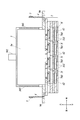
- FIG. 3 is a cross-sectional view of an ink jet head showing a cross section of IV-IV in FIG.
- the conveyance direction of the recording medium R is the front-rear direction
- the direction perpendicular to the conveyance direction on the conveyance surface of the recording medium R is the left-right direction
- the direction perpendicular to the front-rear direction and the left-right direction is the vertical direction.
- the ink jet recording apparatus 100 includes a platen 1001, a transport roller 1002, line heads 1003, 1004, 1005, 1006, an ink circulation mechanism 8, and the like (see FIGS. 1 and 6).
- the platen 1001 supports the recording medium R on the upper surface, and when the conveying roller 1002 is driven, the recording medium R is conveyed in the conveying direction (front-rear direction).
- the line heads 1003, 1004, 1005, and 1006 are provided in parallel in the width direction (left-right direction) orthogonal to the transport direction from the upstream side to the downstream side in the transport direction (front-rear direction) of the recording medium R.
- the line heads 1003, 1004, 1005, 1006 are provided with at least one inkjet head 1 to be described later. For example, cyan (C), magenta (M), yellow (Y), black (K ) Is ejected toward the recording medium R.
- the ink circulation mechanism 8 will be described later (see FIG. 6).
- FIG. 3 is a plan view of the head chip 2, and some of the components formed inside the head chip 2 are indicated by broken lines.
- the inkjet head 1 includes a head chip 2, a common ink chamber 3, a connection member 4, a holding unit 90, and the like (see FIGS. 2 to 5 and the like).
- the head chip 2 is configured by laminating a plurality of substrates in the upward direction, and a plurality of nozzles N for ejecting ink are provided on the lowermost substrate (see FIG. 2B).
- a pressure chamber 311 for storing ink corresponding to each nozzle N and a piezoelectric element 42 as pressure generating means are provided inside the head chip 2.
- a large number of ink supply holes 601 are provided in the uppermost layer of the head chip 2 (see FIGS. 3 and 5), and the common ink chamber 3 passes through the ink supply holes 601. Ink is supplied to the pressure chamber 311.
- the ink stored in the pressure chamber 311 is pressurized by the displacement of the piezoelectric element 42, and ink droplets are ejected from the nozzle N.
- the common ink chamber 3 includes a common supply liquid chamber 3a and two common discharge liquid chambers 3b (see FIG. 2A and the like). For example, cyan (C) and magenta (M) are provided in the respective ink chambers. One color of yellow (Y) and black (K) is filled.
- the common supply liquid chamber 3 a is provided in the upper surface of the head chip 2 and in the central portion of the common ink chamber 3, and is supplied in common to each of the pressure chambers 311 from the ink supply hole 601 opening in the upper surface of the head chip 2.
- the ink to be stored is stored.
- an ink supply port 301 is provided above the common supply liquid chamber 3 a, and ink is supplied from the ink supply port 301 by the ink circulation mechanism 8.
- a second damper 303 is formed on a part of the outer peripheral wall in the front-rear direction of the common supply liquid chamber 3a (see FIG. 4).
- the second damper 303 is formed of an elastic resin such as polyimide, or a metal member such as stainless steel, and prevents the internal pressure of the common ink chamber 3 from rapidly increasing or decreasing.
- Two common discharge liquid chambers 3b are provided on the end side in the left-right direction of the common ink chamber 3, and store the ink discharged from the ink discharge holes 602 opened on the upper surface of the head chip 2.
- An ink discharge port 302 is provided above the common discharge chamber 3b, and ink in the common discharge chamber 3b is transferred from the ink discharge port 302 to the outside of the inkjet head 1 by the ink circulation mechanism 8. Is discharged.
- the connecting member 4 is a wiring member connected to the driving unit 5 made of, for example, FPC, and is connected to the individual wiring 57 on the upper surface of the wiring substrate 50 at the front and rear end portions of the head chip 2. Then, electricity is supplied from the drive unit 5 to the piezoelectric element 42 through the connection member 4 and the individual wiring 57.
- the holding unit 90 is bonded to the upper surface of the head chip 2 and supports the common ink chamber 3.
- the common ink chamber 3 can be provided on the upper surface of the head chip 2 with high accuracy since the common ink chamber 3 can be provided using the holding portion 90 as a mark after the holding portion 90 is provided in alignment with the upper surface of the head chip 2. can do. Further, from the viewpoint of performing alignment with high accuracy, it is desirable to provide an alignment mark (not shown) on each of the head chip 2 and the holding unit 90 and join them.
- the head chip 2 is configured by stacking and integrating a nozzle substrate 10, a common flow path substrate 70, an intermediate substrate 20, a pressure chamber substrate 30, a spacer substrate 40, a wiring substrate 50, and an adhesive layer 60 in order from the bottom. (See FIG. 5).
- the nozzle substrate 10 has a nozzle N, a large-diameter portion 101 that communicates with the nozzle N and has a diameter larger than that of the nozzle N, and an individual circulation passage 102 that is branched from the large-diameter portion 101 and used for ink circulation. And are formed.
- the nozzles N are provided, for example, in a plurality of rows (for example, 4 rows) along the left-right direction (see FIG. 2).
- the nozzle substrate 10 is manufactured by an SOI substrate, and is processed and formed with high accuracy by anisotropic etching. Therefore, the length of the nozzle N in the vertical direction and the thickness of the lower portion of the individual circulation channel 102 can be reduced to, for example, about 10 ⁇ m.
- the individual circulation channel 102 is provided to be branched to the large-diameter portion 101 at the upper part of the nozzle N, it is possible to circulate the ink in the vicinity of the nozzle N, and to individually separate bubbles and the like in the vicinity of the nozzle N. It can be passed through the circulation channel 102.
- the common flow path substrate 70 is a substrate made of silicon, and the common flow path substrate 70 is formed with a large diameter portion 701, a throttle portion 702, and a common circulation flow path 703.
- the large diameter portion 701 penetrates the common flow path substrate 70 in the vertical direction, and communicates with the large diameter portion 101 of the nozzle substrate 10 with the same diameter.
- a row of individual circulation flow paths 102 arranged in the arrangement direction (left-right direction) of the nozzles N communicate with each other through the throttle portion 702, and the ink flowing from the plurality of individual circulation flow paths 102 is flown. Join.
- the common circulation channel 703 is provided along the arrangement direction (left-right direction) of the nozzles N, and a channel is formed upward near the right end and the left end of the head chip 2.
- the ink discharge holes 602 communicate with each other (see FIG. 3 and the like).
- the individual circulation channel 102, the throttle unit 702, and the common circulation channel 703 are collectively referred to as a circulation channel 72. If the flow path impedance of the individual circulation flow path 102 can be made sufficiently large, the throttle portion 702 can be omitted.
- a first damper 704 is formed on the common flow path substrate 70.
- the first damper 704 is made of, for example, elastically deformable silicon, metal, or resin, and the common flow path substrate 70 may have a configuration in which a plurality of layers are laminated by bonding or the like.
- the first damper 704 is made of, for example, a Si substrate having a thickness of 1 to 50 ⁇ m and is provided facing the upper surface of the common circulation channel 703, and the air chamber 203 is formed on the upper surface of the first damper 704. . Since the first damper 704 is a thin Si substrate, it can be elastically deformed by the pressure difference between the common circulation channel 703 and the air chamber 203 to change the volume of the common circulation channel 703.
- the common circulation flow path 703 communicates with one row of individual circulation flow paths 102 arranged in the arrangement direction (left-right direction) of the nozzles N, but two rows of individual circulation flow paths 102 communicate with each other. It may be configured.
- the intermediate substrate 20 is a glass substrate, and the intermediate substrate 20 has a communication hole 201 penetrating in the vertical direction and a space that is concave upward in the upper surface of the first damper 704 and becomes the air chamber 203.
- the part is formed.
- the communication hole 201 communicates with the large diameter portion 701.
- the communication hole 201 has a shape that narrows the diameter of the path through which the ink passes, and is formed so as to adjust the kinetic energy applied to the ink when the ink is ejected.
- the communication hole 201, the large diameter part 701, and the large diameter part 101 are collectively referred to as a communication path 71.
- the pressure chamber substrate 30 includes a pressure chamber layer 31 and a diaphragm 32.
- the pressure chamber layer 31 is a silicon substrate, and a pressure chamber 311 in which ink ejected from the nozzle N is stored is formed in the pressure chamber layer 31.
- the pressure chambers 311 are provided in a plurality of rows (for example, 4 rows) corresponding to the nozzle rows and arranged in the left-right direction (see FIG. 3).
- the pressure chamber 311 communicates with a communication path 71 serving as a flow path when ink is ejected in a lower portion in the front direction (pressure chamber outlet 311b).
- the pressure chamber 311 is formed so as to extend in the front-rear direction while penetrating the pressure chamber layer 31 in the up-down direction.
- the diaphragm 32 is laminated on the upper surface of the pressure chamber layer 31 so as to cover the opening of the pressure chamber 311, and constitutes the upper wall portion of the pressure chamber 311.
- An oxide film is formed on the surface of the diaphragm 32.
- the diaphragm 32 is formed with a through hole 321 that communicates with the pressure chamber 311 and penetrates upward.
- the spacer substrate 40 is a substrate made of 42 alloy, and is a partition layer that forms a space 41 for accommodating the piezoelectric element 42 and the like between the diaphragm 32 and the wiring substrate 50.
- the piezoelectric element 42 is formed in substantially the same plan view shape as the pressure chamber 311, and is provided at a position facing the pressure chamber 311 with the diaphragm 32 interposed therebetween.
- the piezoelectric element 42 is an actuator made of PZT (lead zirconium titanate) for deforming the diaphragm 32.
- the piezoelectric element 42 is provided with two electrodes 421 and 422 on the upper surface and the lower surface, and the electrode 422 on the lower surface side is connected to the diaphragm 32.
- a through hole 401 communicating with the through hole 321 of the diaphragm 32 and penetrating upward is formed in the spacer substrate 40 independently of the space 41.
- the wiring board 50 includes an interposer 51 that is a silicon substrate.
- the lower surface of the interposer 51 is covered with two layers of insulating layers 52 and 53 of silicon oxide, and the upper surface is also covered with an insulating layer 54 of silicon oxide.
- the insulating layer 53 positioned below the insulating layers 52 and 53 is laminated on the upper surface of the spacer substrate 40.
- a through hole 511 penetrating upward is formed in the interposer 51, and the through electrode 55 is inserted into the through hole 511.
- One end of a wiring 56 extending in the horizontal direction is connected to the lower end of the through electrode 55, and a stud bump 423 provided on the electrode 421 on the upper surface of the piezoelectric element 42 is connected to the other end of the wiring 56.
- the individual wiring 57 is connected to the upper end of the through electrode 55, and the individual wiring 57 extends in the horizontal direction and is connected to the connection member 4 (see FIG. 4).
- the interposer 51 is formed with an inlet 512 that communicates with the through hole 401 of the spacer substrate 40 and penetrates upward.
- each portion covering the vicinity of the inlet 512 is formed to have an opening diameter larger than that of the inlet 512.
- the adhesive layer 60 is a layer that adheres to the holding unit 90 and is a photosensitive resin layer, and is a protective layer that protects the individual wiring 57.
- the adhesive layer 60 covers the individual wiring 57 disposed on the upper surface of the wiring substrate 50, while interposer. It is laminated on the upper surface of 51 insulating layers 54.
- the adhesive layer 60 has an ink supply hole 601 that communicates with the inlet 512 and penetrates upward.
- Ink circulation path inside the head chip 2 will be described.
- Ink is supplied from the common supply liquid chamber 3 a of the common ink chamber 3 to the inside of the head chip 2 through the ink supply hole 601 provided corresponding to each nozzle N.
- the ink sequentially flows into the inlets 512,..., The through holes 401,.
- the ink flows into the communication passages 71,... (Communication holes 201,..., The large diameter portion 701,..., The large diameter portion 101,.
- the ink flows into the individual circulation channels 102 branched from the large diameter portions 101,..., And the ink from the plurality of individual circulation channels 102,. Join at.
- the common circulation channel 703 flows toward the end of the head chip 2 in the left direction or the right direction, and finally the common discharge of the common ink chamber 3 from the ink discharge hole 602 provided in the upper surface of the head chip. It is discharged into the liquid chamber 3b (see FIG. 3 etc.).
- the individual circulation channel 102 is shown as being branched from the communication passage 71 that connects the nozzle N and the pressure chamber 311, but the inlet N11a of the pressure chamber 311 is connected to the nozzle N. It suffices if it is branched from the ink flow path reaching the outlet Nb.
- the individual circulation channel 102 is preferably provided by branching from a portion from the end of the pressure chamber 311 on the outlet 311b side to the outlet Nb of the nozzle N in the ink channel.
- the inlet 311a (ink inlet) and outlet 311b (ink outlet communicating with the inlet Na of the nozzle N) and the inlet Na (ink inlet) and outlet Nb (ink outlet) of the nozzle N are shown in FIG. Show.
- the circulation flow path 72 is branched from the nozzle N
- the nozzle formation substrate corresponds to the surface of the nozzle formation substrate on the pressure chamber 311 side.
- the circulation channel 72 can be configured by forming a groove to be the circulation channel 72 formed and joining the nozzle forming substrate to the channel substrate in which a channel communicating with the nozzle N is formed.
- the common circulation channel 703 and the diaphragm may be formed on the nozzle forming substrate or may be formed on the channel substrate.
- a groove (individual circulation flow path 102) that reaches the common circulation flow path 703 is formed on the nozzle formation board corresponding to each nozzle N and adjacent to one side, It is preferable that the circulation flow path 72 is configured by joining the nozzle forming substrate to a flow path substrate on which a throttle or common circulation flow path 703 is formed.
- a nozzle N as a through hole is formed in the nozzle substrate 10 to form a nozzle forming substrate, and the nozzle forming substrate is formed in communication with each nozzle N on the surface on the common flow path substrate 70 side. Then, it reaches the narrowed portion 702 adjacent to the other side, forms a groove to be the individual circulation flow path 102, and this nozzle forming substrate is joined to the common flow path substrate 70 (flow path substrate), thereby branching from the nozzle N
- the individual circulation flow path 102, the throttle portion 702, and the common circulation flow path 703 can be formed.
- the circulation flow path 72 when the circulation flow path 72 is branched from the nozzle N, it is preferable to have a tapered shape in which the hole diameter of the nozzle N gradually decreases from the inlet Na side of the nozzle N.
- circulation is formed on the surface of the pressure chamber substrate 30 on which the pressure chamber 311 is formed corresponding to each pressure chamber 311. It is preferable to form the circulation flow path 72 by forming a groove to be the flow path 72 and joining the pressure chamber substrate to a flow path substrate in which a flow path communicating with the pressure chamber 311 is formed.
- the common circulation channel 703 and the restriction may be formed on the pressure chamber substrate 30 or on the channel substrate.
- the pressure chamber substrate 30 is formed corresponding to each pressure chamber 311 and formed on one side adjacent to the throttle or the groove reaching the common circulation flow path 703 (individual circulation flow path 102),
- the pressure chamber substrate 30 is preferably joined to a flow path substrate on which a throttle and a common circulation flow path 703 are formed, so that the circulation flow path 72 is configured.
- the individual circulation flow path 102 of the nozzle substrate 10 is eliminated, the intermediate substrate 20 is used as an Si substrate, the common circulation flow path 703, the throttle unit 702, and the first damper 704 are combined with the throttle unit 702 and the first one.
- the upper and lower positions of the damper 704 are switched to form the throttle portion 702 at the upper portion and the rear end portion of the common circulation flow path 703, and the air chamber 203 is formed above the common flow path substrate 70.
- the common circulating flow path 703, the throttle portion 702, the first portion are arranged so that the throttle portion 702 is disposed at a position shifted to the rear side of FIG. 5 so as not to overlap the pressure chamber 311 when viewed from the vertical direction in FIG.
- the pressure chamber substrate 30 forming the pressure chamber 311 is formed on the surface on the intermediate substrate 20 side so as to communicate with each pressure chamber 311 and reach the constricted portion 702 adjacent to the other side, and a groove serving as the individual circulation channel 102 is formed.
- the individual circulation channel 102, the throttle portion 702, and the common circulation channel 703 can be formed.
- the throttle unit 702 may be a common circulation channel 703.
- the ink circulation mechanism 8 as the ink circulation means includes a supply sub tank 81, a circulation sub tank 82, a main tank 83, and the like (FIG. 6).
- the supply sub tank 81 is filled with ink to be supplied to the common supply liquid chamber 3 a of the common ink chamber 3, and is connected to the ink supply port 301 by the ink flow path 84.
- the circulation sub tank 82 is filled with the ink discharged from the common discharge liquid chamber 3 b of the common ink chamber 3, and is connected to the ink discharge ports 302 and 302 by the ink flow path 85.
- the supply sub-tank 81 and the circulation sub-tank 82 are provided at different positions in the vertical direction (gravity direction) with respect to the nozzle surface (hereinafter also referred to as “position reference surface”) of the head chip 2.
- a pressure P1 due to a water head difference between the position reference surface and the supply sub tank 81 and a pressure P2 due to a water head difference between the position reference surface and the circulation sub tank 82 are generated.
- the supply sub-tank 81 and the circulation sub-tank 82 are connected by an ink flow path 86. Ink can be returned from the circulation sub-tank 82 to the supply sub-tank 81 by the pressure applied by the pump 88.
- the main tank 83 is filled with ink to be supplied to the supply sub-tank 81, and is connected to the supply sub-tank 81 by the ink flow path 87. Ink can be supplied from the main tank 83 to the supply sub-tank 81 by the pressure applied by the pump 89.
- the pressure P1 and the pressure P2 can be adjusted by adjusting the ink amount in each sub-tank as described above, and by changing the position of each sub-tank in the vertical direction (gravity direction). Then, the ink above the nozzle N can be circulated at an appropriate circulation flow rate by the pressure difference between the pressure P1 and the pressure P2. Thereby, bubbles generated in the head chip 2 can be removed, and clogging of the nozzle N, injection failure, and the like can be suppressed.
- the common supply liquid chamber 3 a is provided on the upper surface of the head chip 2, and stores ink that is commonly supplied to each of the pressure chambers 311 from the ink supply hole 601 opening on the upper surface of the head chip 2. Yes. In this way, by providing the common supply liquid chamber 3a that requires a relatively large volume on the upper surface of the head chip 2, even in a small inkjet head 1, a space for providing the common supply liquid chamber 3a is provided. The structure is easy to secure. If the volume of the common supply liquid chamber 3a is increased, the viscosity resistance R and the inertance L of the common supply liquid chamber 3a can be reduced.
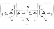
- a method of calculating the viscous resistance R (R 1 to R 4 ), the inertance L (L 1 to L 4 ) of the flow path, and the compliance C (C 1 , C 4 ) of the flow path in the equivalent circuit model will be described.
- the channel shape is a rectangular parallelepiped
- the channel width (front-rear direction) is w (m)
- the channel height (vertical direction) is h (m)
- the channel length (left-right direction) is l.
- the flow path shape is a cylindrical shape
- the diameter of the flow path is d (m)
- the height (vertical direction) of the flow path is l (m)
- the fluid viscosity of the ink is ⁇ (Pa ⁇ s)
- it can be calculated by subdividing and integrating as a rectangular parallelepiped in the length direction of the taper shape.
- the viscous resistance R and inertance L in A2 and A3 it is calculated as the sum of the numerical values of the respective channels, assuming that the respective channels are connected in series.
- C1 corresponds to the second damper 303
- C4 corresponds to the first damper 704.
- the compliance C is the reciprocal of the spring constant, and can be calculated by using, for example, a finite element method to convert “pL / MPa” to “nF”.
- Table 1 shows values of inertance L, viscous resistance R, and compliance C for an example in which the inkjet head 1 of the present invention is designed by the above calculation method.
- Each numerical value of A2 and A3 is obtained by dividing the ink flow path corresponding to each nozzle N by the number of nozzles N provided in the head chip 2 (1024).
- Inertance L and viscous resistance R of A4 are obtained by dividing the value of each common circulation flow path 703 by the number thereof, and compliance C is obtained by multiplying the number.
- the inertance L and the viscous resistance R can be designed to be small by setting values as shown in Table 1.
- each of the common supply liquid chamber 3a (A1) and the common circulation flow path 703 (A4) calculates the inertance L and the viscous resistance R when the flow path shape is a rectangular parallelepiped.
- the common supply liquid chamber 3a can make the width
- the viscous resistance R4 can be designed to be very small.
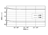
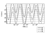
- FIG. 8 shows the simulation result of the ink flow rate.
- the common supply liquid chamber 3a side (A1 and A2 side) from the point B2 is the upstream side
- the circulation flow path 72 side (A3 and A4 side) from the point B2 is the downstream side
- the nozzle N from the upstream side.
- the ink flow rate flowing toward the upper portion is a positive value
- the ink flow rate flowing from the downstream side toward the upper portion of the nozzle N is a negative value.
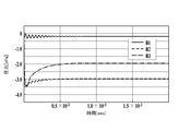
- the pressure fluctuation in the flow path can be calculated on the assumption that the current is ejected from the nozzle N and the voltage is the pressure in the flow path in the above-described equivalent circuit model.
- the pressure fluctuation at the point B2 indicates the pressure fluctuation at the upper part of the nozzle N. If the pressure fluctuation at the point B2 is small, the ejection stability of the ink becomes high. In the simulation result shown in FIG.
- the pressure fluctuation at the point B2 is approximately in the range of ⁇ 3.5 to ⁇ 3.0 kPa, and the pressure fluctuation amount is about 0.5 kPa. Therefore, although the simulated ink ejection conditions are 6 pL of ejected droplet volume, 50 kHz drive frequency, 1024 nozzles, and the flow rate of ejected ink is very high, the pressure fluctuation It was found that can be suppressed to a low level of about 0.5 kPa.
- the pressure fluctuation of 0.5 kPa is equivalent to the ink sub-tank head value of 5 cm, and the influence on the ejection speed is small. As described above, it was confirmed that the ink jet head 1 of the present invention has very high ink ejection stability.
- FIG. 10 the simulation results corresponding to FIG. 8 and the simulation results corresponding to FIG. 9 are shown in FIG. 10 and FIG. Shown in As shown in FIG. 10, when the inertance L1 is increased by 100 times, the supply of ink from the upstream side decreases, the ink becomes more difficult to be supplied from the upstream side, and the supply from the downstream side increases. Further, as shown in FIG. 11, the pressure fluctuation at the point B2 is a large value of 4 kPa or more. Thus, by increasing the inertance L1, the pressure fluctuation increases, and the injection stability decreases.
- the ink jet head 1 of the present invention is provided to be branched from the ink flow path from the inlet 311a of the pressure chamber 311 to the outlet Nb of the nozzle N, and can discharge the ink in the plurality of pressure chambers 311.
- a head chip 2 having a plurality of individual circulation channels 102 and a common circulation channel 703 in which at least two of the plurality of individual circulation channels 102 communicate with each other, and provided on the upper surface of the head chip 2.
- a common supply liquid chamber 3a for storing ink to be supplied in common to each of the plurality of pressure chambers 311 from a plurality of ink supply holes 601 opened on the upper surface.
- the small-sized inkjet head 1 it is easy to secure a volume for providing the common supply liquid chamber 3a, and the viscosity resistance R and the inertance L of the common supply liquid chamber 3a can be reduced. Therefore, when the pressure chamber 311 becomes negative pressure due to the ejection of ink from the nozzle N, most of the ink can be supplied from the common supply liquid chamber 3a, and the ink is drawn from the circulation channel 72 toward the pressure chamber 311 side. Therefore, it is possible to suppress the pressure fluctuation in the vicinity of the nozzle N and improve the ink ejection stability. Moreover, since the inkjet head 1 of the present invention can be miniaturized, it is possible to reduce the size and increase the resolution, thereby reducing the production cost.
- the ink jet head 1 of the present invention has the individual circulation flow path 102 branched from the portion from the end on the outlet 311b side of the pressure chamber 311 to the outlet Nb of the nozzle N, so that ink in the vicinity of the nozzle N is provided. Can be circulated.
- the inkjet head 1 of the present invention has a communication path 71 that communicates the nozzle N and the pressure chamber 311, and the individual circulation channel 102 is provided by branching from the communication path 71. Near ink can be circulated.
- the common circulation channel 703 and the pressure chamber 311 are provided at a position where at least a part thereof overlaps in the ink ejection direction of the nozzle N. Thereby, the inkjet head 1 can be further reduced in size.
- a plurality of nozzles N are arranged in a plurality of rows, and a common circulation channel 703 is provided for each of the plurality of rows or every two rows.
- the head chip 2 can be reduced in size.
- the inkjet head 1 of the present invention includes a first damper 704 provided facing at least one of the individual circulation channel 102 and the common circulation channel 703. Thereby, pressure fluctuations in the ink flow path can be further suppressed.
- the inkjet head 1 of the present invention includes a first damper 704 provided facing at least one of an upper part and a lower part of the common circulation channel 703, and the first damper 704 is defined as the common circulation channel side.
- an air chamber 203 is provided facing the first damper 704.
- the ink jet head 1 of the present invention includes a second damper 303 provided facing the common supply liquid chamber 3a. Thereby, pressure fluctuations in the ink flow path can be further suppressed.
- the configuration of the first damper 704 and the second damper 303 can be changed as appropriate as long as they can be elastically deformed.
- it may be formed of a stainless steel plate having an appropriate thickness.
- the 1st damper 704 should just be provided so that the circulation flow path 72 may be faced, and a magnitude
- it is preferably provided on the upper surface or the lower surface of the circulation flow path 72, but it can also be provided on the left surface or the right surface.
- the method for controlling the circulation of the ink by the water head difference has been described as the ink circulation mechanism 8, it can be appropriately changed as long as it is a configuration capable of generating a circulation flow as in the present invention.
- the inkjet head 1 is configured to eject droplets of ink or the like using a piezoelectric element, but may be provided with a mechanism capable of ejecting droplets.
- a thermal (electrothermal conversion element) is used. It is also good to do.
- the present invention can be used for an inkjet head and an inkjet recording apparatus.
Abstract
本発明の課題は、小型で高解像度化が可能であり、射出安定性を向上でき、生産コストを低減させることができる、インクの循環が可能な流路を有するインクジェットヘッド等を提供することである。本発明のインクジェットヘッド1は、複数のノズルNと、ノズルNの各々に連通する複数の圧力室311と、複数の圧力室311に対応して設けられた複数の圧電素子42と、圧力室311の入口311aからノズルNの出口Nbに至るインク流路から分岐して設けられ、圧力室311内のインクを排出可能な複数の個別循環流路102と、複数の個別循環流路102のうち少なくとも二つが連通する共通循環流路703と、を備えるヘッドチップ2と、ヘッドチップ2の上面に設けられ、ヘッドチップ2の上面に開口する複数のインク供給孔601から、複数の圧力室311の各々に共通に供給するインクを貯留する共通供給液室3aと、を備えることを特徴とする。
Description
本発明は、インクジェットヘッド及びインクジェット記録装置に関する。
従来、インクジェットヘッドに備えられた複数のノズルからインクの液滴を射出して記録媒体に画像を形成するインクジェット記録装置が知られている。
このようなインクジェット記録装置では、インクジェットヘッド内に発生した気泡や混入した異物等によって、ノズルが詰まり、射出不良等の問題が生じる場合がある。また、インクの種類によっては、長時間使用しないままにしておくと、インク粒子の沈降等によってノズル付近のインク粘度が高まり、安定したインクの射出性能が得難い場合がある。
このようなインクジェット記録装置では、インクジェットヘッド内に発生した気泡や混入した異物等によって、ノズルが詰まり、射出不良等の問題が生じる場合がある。また、インクの種類によっては、長時間使用しないままにしておくと、インク粒子の沈降等によってノズル付近のインク粘度が高まり、安定したインクの射出性能が得難い場合がある。
そこで、インクジェットヘッドのヘッドチップにインクの循環が可能な循環流路を設けることによって、ヘッド内の気泡等をインクとともに当該循環流路に流すことができるインクジェット記録装置が知られている。
例えば、特許文献1には、複数列に配列されたノズルと、各ノズルに連通する各圧力室(ポンプ室)のそれぞれに対してインクを共通に供給する共通供給流路(流体入口通路)と、各ノズル付近のインクを排出する個別循環流路が複数連通する共通循環流路(再循環チャンネル)を備えるインクジェットヘッドが開示されている。
ところで、近年、インクジェットヘッドの小型化や画像の高解像度化のためノズルを高密度に配置することが求められている。しかしながら、特許文献1に記載したような、ヘッドチップに共通供給流路(共通供給液室)と共通循環流路を備える構成では、ヘッドチップ内部に比較的大きな容積が必要となるので、ヘッドチップが大型化し、ノズルを高密度に配置することが難しいという問題がある。また、ヘッドチップが大型化すれば、製造に使用する材料の増加により、生産コストが増加するという問題も生じる。
また、ノズルからインクが射出される際に、圧力室内の圧力がわずかに負圧になるため、圧力室よりも上流側及び下流側のそれぞれのインク流路から、圧力室に向かってインクが引き込まれることが知られている。ここで、特許文献1のようにヘッドチップ内に循環流路を設けた構成では、循環流路からもインクが圧力室に引き込まれる。そして、循環流路がノズルの近くに形成されている場合、ノズル付近の圧力が変動するため、インクの射出安定性が低下し、さらには、ノズルのメニスカスがブレークすることもある。
本発明は、このような問題に鑑みてなされたものであり、本発明の課題は、小型で高解像度化が可能であり、射出安定性が高く、生産コストが安い、インクの循環が可能な流路を有するインクジェットヘッド及びインクジェット記録装置を提供することである。
上記課題の解決のために、請求項1に記載の発明は、インクジェットヘッドであって、
インクを射出する複数のノズルと、
前記複数のノズルの各々に連通し、インクが貯留された複数の圧力室と、
前記複数の圧力室の各々に対応して設けられ、対応する前記圧力室内のインクに圧力を加える複数の圧力発生手段と、
前記圧力室の入口から前記ノズルの出口に至るインク流路から分岐して設けられ、前記複数の圧力室内のインクを排出可能な複数の個別循環流路と、
前記複数の個別循環流路のうち少なくとも二つが連通する共通循環流路と、
を備えるヘッドチップと、
前記ヘッドチップの上面に設けられ、前記ヘッドチップの上面に開口する複数のインク供給孔から、前記複数の圧力室の各々に共通に供給するインクを貯留する共通供給液室と、を備えることを特徴とする。
請求項2に記載の発明は、請求項1に記載のインクジェットヘッドであって、
前記個別循環流路は、前記インク流路のうち前記圧力室の出口側の端部から前記ノズルの出口に至る部分から分岐して設けられていることを特徴とする。
前記個別循環流路は、前記インク流路のうち前記圧力室の出口側の端部から前記ノズルの出口に至る部分から分岐して設けられていることを特徴とする。
請求項3に記載の発明は、請求項1又は2に記載のインクジェットヘッドであって、
前記インク流路は、前記ノズルと、前記圧力室とを連通する連通路を有し、
前記個別循環流路は、前記連通路から分岐して設けられていることを特徴とする。
前記インク流路は、前記ノズルと、前記圧力室とを連通する連通路を有し、
前記個別循環流路は、前記連通路から分岐して設けられていることを特徴とする。
請求項4に記載の発明は、請求項1~3のいずれか一項に記載のインクジェットヘッドであって、
前記共通循環流路と前記複数の圧力室は、前記ノズルのインク射出方向において、少なくとも一部が重なる位置に設けられていることを特徴とする。
前記共通循環流路と前記複数の圧力室は、前記ノズルのインク射出方向において、少なくとも一部が重なる位置に設けられていることを特徴とする。
請求項5に記載の発明は、請求項1~4のいずれか一項に記載のインクジェットヘッドであって、
前記複数のノズルは、複数列で配列されており、
前記複数列の各列又は2列毎に、前記共通循環流路が設けられていることを特徴とする。
前記複数のノズルは、複数列で配列されており、
前記複数列の各列又は2列毎に、前記共通循環流路が設けられていることを特徴とする。
請求項6に記載の発明は、請求項1~5のいずれか一項に記載のインクジェットヘッドであって、
前記個別循環流路及び前記共通循環流路の少なくとも一方に面して設けられ、圧力により弾性変形して流路の容積を変更可能な第1ダンパーを備えることを特徴とする。
前記個別循環流路及び前記共通循環流路の少なくとも一方に面して設けられ、圧力により弾性変形して流路の容積を変更可能な第1ダンパーを備えることを特徴とする。
請求項7に記載の発明は、請求項1~6のいずれか一項に記載のインクジェットヘッドであって、
前記共通循環流路の上部及び下部の少なくとも一方に面して設けられ、圧力により弾性変形して流路の容積を変更可能な第1ダンパーを備え、
前記第1ダンパーは、前記共通循環流路の側とは反対側に、前記第1ダンパーに面して空気室を有していることを特徴とする。
前記共通循環流路の上部及び下部の少なくとも一方に面して設けられ、圧力により弾性変形して流路の容積を変更可能な第1ダンパーを備え、
前記第1ダンパーは、前記共通循環流路の側とは反対側に、前記第1ダンパーに面して空気室を有していることを特徴とする。
請求項8に記載の発明は、請求項1~7のいずれか一項に記載のインクジェットヘッドであって、
前記共通供給液室に面して設けられ、圧力により弾性変形して前記共通供給液室の容積を変更可能な第2ダンパーを備えることを特徴とする。
前記共通供給液室に面して設けられ、圧力により弾性変形して前記共通供給液室の容積を変更可能な第2ダンパーを備えることを特徴とする。
請求項9に記載の発明は、
請求項1~8のいずれか一項に記載のインクジェットヘッドと、
前記インク流路から前記個別循環流路への循環流を発生させるための循環手段を備えることを特徴とするインクジェット記録装置である。
請求項1~8のいずれか一項に記載のインクジェットヘッドと、
前記インク流路から前記個別循環流路への循環流を発生させるための循環手段を備えることを特徴とするインクジェット記録装置である。
本発明によれば、インクの循環が可能な流路を有するインクジェットヘッドにおいて、小型で高解像度化が可能であり、射出安定性を向上でき、生産コストを低減させることができる。
以下、図面を参照しながら、本発明の好ましい実施形態について説明する。但し、発明の範囲は図示例に限定されない。また、以下の説明において、同一の機能及び構成を有するものについては、同一の符号を付し、その説明を省略する。
なお、以下の説明では、ラインヘッドを用いた記録媒体の搬送のみで描画を行う1パス描画方式での実施形態を例にして説明するが、適宜の描画方式に適用可能であり、例えば、スキャン方式やドラム方式を用いた描画方式を採用しても良い。
また、以下の説明では、記録媒体Rの搬送方向を前後方向、記録媒体Rの搬送面において当該搬送方向に直交する方向を左右方向とし、前後方向及び左右方向に垂直な方向を上下方向として説明する。
なお、以下の説明では、ラインヘッドを用いた記録媒体の搬送のみで描画を行う1パス描画方式での実施形態を例にして説明するが、適宜の描画方式に適用可能であり、例えば、スキャン方式やドラム方式を用いた描画方式を採用しても良い。
また、以下の説明では、記録媒体Rの搬送方向を前後方向、記録媒体Rの搬送面において当該搬送方向に直交する方向を左右方向とし、前後方向及び左右方向に垂直な方向を上下方向として説明する。
[インクジェット記録装置の概略]
インクジェット記録装置100は、プラテン1001、搬送ローラー1002、ラインヘッド1003,1004,1005,1006、及びインクの循環機構8等を備える(図1及び図6参照)。
プラテン1001は、上面に記録媒体Rを支持しており、搬送ローラー1002が駆動されると、記録媒体Rを搬送方向(前後方向)に搬送する。
ラインヘッド1003,1004,1005,1006は、記録媒体Rの搬送方向(前後方向)の上流側から下流側にかけて、搬送方向に直交する幅方向(左右方向)に並列して設けられている。そして、ラインヘッド1003,1004,1005,1006の内部には、後述するインクジェットヘッド1が少なくとも一つ設けられており、例えば、シアン(C),マゼンタ(M),イエロー(Y),黒(K)のインクを記録媒体Rに向けて吐出する。
なお、インクの循環機構8については、後述する(図6参照)。
[インクジェットヘッドの概略構成]
インクジェットヘッド1の概略構成について、図2~5に基づいて説明する。
なお、図3は、ヘッドチップ2の平面図であり、ヘッドチップ2の内部に形成される構成要素の一部を破線で示している。
インクジェットヘッド1は、ヘッドチップ2、共通インク室3、接続部材4及び保持部90等を備える(図2~図5等参照)。
インクジェットヘッド1の概略構成について、図2~5に基づいて説明する。
なお、図3は、ヘッドチップ2の平面図であり、ヘッドチップ2の内部に形成される構成要素の一部を破線で示している。
インクジェットヘッド1は、ヘッドチップ2、共通インク室3、接続部材4及び保持部90等を備える(図2~図5等参照)。
ヘッドチップ2は、上方向に複数の基板が積層されて構成されており、最下層の基板には、インクを射出する多数のノズルNが設けられている(図2B参照)。また、ヘッドチップ2の内部には、各ノズルNに対応してインクが貯留される圧力室311及び圧力発生手段としての圧電素子42が設けられている。また、これらの圧力室311に対応して、ヘッドチップ2の最上層に多数のインク供給孔601が設けられており(図3、図5等参照)、共通インク室3からインク供給孔601を通して圧力室311にインクが供給される。そして、圧電素子42の変位によって、圧力室311に貯留されたインクが加圧され、ノズルNからインクの液滴が射出される。
共通インク室3は、共通供給液室3aと、2つの共通排出液室3bを有しており(図2A等参照)、それぞれのインク室には、例えば、シアン(C)、マゼンタ(M)、イエロー(Y)及び黒(K)のうち1色が充填されている。
共通供給液室3aは、ヘッドチップ2の上面、かつ共通インク室3の中央部に設けられており、ヘッドチップ2の上面に開口するインク供給孔601から、圧力室311の各々に共通に供給するインクを貯留している。また、共通供給液室3aの上部には、インク供給口301が設けられており、インクの循環機構8によってインク供給口301からインクが供給される。また、共通供給液室3aの前後方向の外周壁の一部には、第2ダンパー303が形成されている(図4参照)。第2ダンパー303は、弾性力のあるポリイミドなどの樹脂やステンレスなどの金属部材によって形成されており、共通インク室3の内圧が急激に上昇又は低下することを防いでいる。
共通排出液室3bは、共通インク室3の左右方向の端部側に2つ設けられており、ヘッドチップ2の上面に開口するインク排出孔602から排出されたインクを貯留している。また、共通排出液室3bの上部には、インク排出口302が設けられており、インクの循環機構8によって、共通排出液室3b内のインクがインク排出口302からインクジェットヘッド1の外部にインクが排出される。
接続部材4は、例えばFPC等からなる駆動部5に接続する配線部材であり、ヘッドチップ2の前後方向の端部で、配線基板50の上面の個別配線57に接続している。そして、駆動部5から、接続部材4と個別配線57を通じて、圧電素子42に電気が供給される。
保持部90は、ヘッドチップ2の上面に接合されており、共通インク室3を支持している。保持部90をヘッドチップ2の上面に位置合わせして設けた後に、保持部90を目印として共通インク室3を設けることができるため、共通インク室3をヘッドチップ2の上面に高精度に形成することができる。
また、高精度に位置合わせを行う観点から、ヘッドチップ2と保持部90のそれぞれにアライメントマーク(図示省略)を設けて、接合することが望ましい。
また、高精度に位置合わせを行う観点から、ヘッドチップ2と保持部90のそれぞれにアライメントマーク(図示省略)を設けて、接合することが望ましい。
[ヘッドチップ]
次に、ヘッドチップ2について、詳細に説明する。
ヘッドチップ2は、下側から順にノズル基板10、共通流路基板70、中間基板20、圧力室基板30,スペーサー基板40,配線基板50及び接着層60が積層一体化されることによって構成されている(図5参照)。
次に、ヘッドチップ2について、詳細に説明する。
ヘッドチップ2は、下側から順にノズル基板10、共通流路基板70、中間基板20、圧力室基板30,スペーサー基板40,配線基板50及び接着層60が積層一体化されることによって構成されている(図5参照)。
ノズル基板10には、ノズルNと、ノズルNと連通しノズルNよりも径の大きな大径部101と、大径部101から分岐して設けられインクの循環に使用される個別循環流路102と、が形成されている。ノズルNは、例えば、左右方向に沿って、複数列(例えば、4列)に並んで設けられている(図2参照)。
また、ノズル基板10は、SOI基板によって製造されており、異方性エッチングにより高精度に加工されて形成されている。そのため、ノズルNの上下方向の長さ及び個別循環流路102の下部の厚みは、例えば10μm程度に薄くすることができる。また、個別循環流路102は、ノズルNの上部の大径部101に分岐して設けられているため、ノズルNの近傍のインクを循環させることができ、ノズルNの近傍の気泡等を個別循環流路102に流すことができる。
また、ノズル基板10は、SOI基板によって製造されており、異方性エッチングにより高精度に加工されて形成されている。そのため、ノズルNの上下方向の長さ及び個別循環流路102の下部の厚みは、例えば10μm程度に薄くすることができる。また、個別循環流路102は、ノズルNの上部の大径部101に分岐して設けられているため、ノズルNの近傍のインクを循環させることができ、ノズルNの近傍の気泡等を個別循環流路102に流すことができる。
共通流路基板70は、シリコン製の基板であり、共通流路基板70には、大径部701と、絞り部702と、共通循環流路703と、が形成されている。
大径部701は、共通流路基板70を上下方向に貫通しており、ノズル基板10の大径部101と同径でそれぞれが連通している。
共通循環流路703は、ノズルNの配列方向(左右方向)に並んだ一列分の個別循環流路102が絞り部702を通じて連通しており、複数の個別循環流路102から流れてきたインクが合流する。また、共通循環流路703は、ノズルNの配列方向(左右方向)に沿って設けられ、ヘッドチップ2の右端部及び左端部付近で上方向に流路が形成されており、ヘッドチップ2上面のインク排出孔602に連通している(図3等参照)。また、以下の説明では、個別循環流路102と、絞り部702と、共通循環流路703を合わせて循環流路72という。個別循環流路102の流路インピーダンスを十分大きくすることが出来れば、絞り部702を省略することもできる。
また、共通流路基板70には、第1ダンパー704が形成されている。第1ダンパー704は、例えば、弾性変形可能なシリコン、金属又は樹脂などからなり、共通流路基板70は、複数の層を接着などで積層した構成としてもよい。
第1ダンパー704は、例えば、厚さ1~50μmからなるSi基板からなり、共通循環流路703の上面に面して設けられ、第1ダンパー704の上面には空気室203が形成されている。第1ダンパー704は、薄いSi基板であるため、共通循環流路703と空気室203との圧力差によって弾性変形して、共通循環流路703の容積を変更可能である。例えば、圧力室311に一度に圧力が加えられ射出が行われ、共通循環流路703に一度にインクが流れて共通循環流路703内の圧力が急激に下がった場合、第1ダンパー704が下方向に向かって弾性変形することにより、インク流路の急激な圧力変動を防ぐことができる。また、空気室203を閉空間とすることで、第1ダンパー704が変形に伴う振動を起こした場合の減衰力が働き、さらに圧力変動を抑えることができる。
なお、共通循環流路703には、ノズルNの配列方向(左右方向)に並んだ一列分の個別循環流路102が連通するとしたが、二列分の個別循環流路102が連通するように構成しても良い。
中間基板20は、ガラス製の基板であり、中間基板20には、上下方向に貫通する連通孔201と、第1ダンパー704の上面に、空気室203となる上方向に向かって凹となる空間部が形成されている。
連通孔201は、大径部701に連通している。また、連通孔201は、インクが通過する経路の径を絞る形状となっており、インクの射出においてインクに加えられる運動エネルギーを調整するように形成されている。また、以下の説明では、連通孔201、大径部701及び大径部101を合わせて連通路71という。
連通孔201は、大径部701に連通している。また、連通孔201は、インクが通過する経路の径を絞る形状となっており、インクの射出においてインクに加えられる運動エネルギーを調整するように形成されている。また、以下の説明では、連通孔201、大径部701及び大径部101を合わせて連通路71という。
圧力室基板30は、圧力室層31と振動板32からなる。
圧力室層31は、シリコン製の基板であり、圧力室層31には、ノズルNから射出されるインクが貯留される圧力室311が形成されている。また、圧力室311は、ノズル列に対応して複数列(例えば、4列)で、左右方向に配列して設けられている(図3参照)。また、圧力室311は、前方向の下部(圧力室の出口311b)において、インクが射出される際の流路となる連通路71に連通している。また、圧力室311は、圧力室層31を上下方向に貫通しつつ前後方向に延在するように形成されている。
振動板32は、圧力室311の開口を覆うように圧力室層31の上面に積層され、圧力室311の上壁部を構成している。振動板32の表面には、酸化膜が形成されている。また、振動板32には、圧力室311と連通して上方向に貫通する貫通孔321が形成されている。
スペーサー基板40は、42アロイにより構成された基板であり、振動板32と配線基板50との間に、圧電素子42等を収容するための空間41を形成する隔壁層である。
圧電素子42は、圧力室311と略同一の平面視形状で形成され、振動板32を挟んで圧力室311と対向する位置に設けられている。圧電素子42は、振動板32を変形させるためのPZT(lead zirconium titanate)からなるアクチュエーターである。また、圧電素子42には、上面及び下面に2つの電極421,422が設けられており、このうち下面側の電極422が振動板32に接続されている。
また、スペーサー基板40には、振動板32の貫通孔321と連通して上方向に貫通する貫通孔401が、空間41とは独立して形成されている。
圧電素子42は、圧力室311と略同一の平面視形状で形成され、振動板32を挟んで圧力室311と対向する位置に設けられている。圧電素子42は、振動板32を変形させるためのPZT(lead zirconium titanate)からなるアクチュエーターである。また、圧電素子42には、上面及び下面に2つの電極421,422が設けられており、このうち下面側の電極422が振動板32に接続されている。
また、スペーサー基板40には、振動板32の貫通孔321と連通して上方向に貫通する貫通孔401が、空間41とは独立して形成されている。
配線基板50は、シリコン製の基板であるインターポーザ51を備えている。インターポーザ51の下面には、2層の酸化ケイ素の絶縁層52,53が被覆され、上面には、同じく酸化ケイ素の絶縁層54が被覆されている。そして、絶縁層52,53のうち下方に位置する絶縁層53が、スペーサー基板40の上面に積層されている。
インターポーザ51には、上方向に貫通するスルーホール511が形成されており、このスルーホール511には、貫通電極55が挿通されている。貫通電極55の下端には、水平方向に延在する配線56の一端が接続されており、この配線56の他端には、圧電素子42上面の電極421上に設けられたスタッドバンプ423が、空間41内に露出した半田561を介して接続されている。また、貫通電極55の上端には、個別配線57が接続されており、個別配線57は水平方向に延在し、接続部材4に接続されている(図4参照)。
また、インターポーザ51には、スペーサー基板40の貫通孔401と連通して上方向に貫通するインレット512が形成されている。なお、絶縁層52~54のうち、インレット512近傍を被覆する各部分は、インレット512よりも大きい開口径となるように形成されている。
接着層60は、保持部90と接着する層で感光性樹脂層であるとともに、個別配線57を保護する保護層であり、配線基板50の上面に配設された個別配線57を覆いつつ、インターポーザ51の絶縁層54の上面に積層されている。また、接着層60には、インレット512と連通して上方向に貫通するインク供給孔601が形成されている。
次に、ヘッドチップ2内部のインクの循環経路について説明する。インクは、共通インク室3の共通供給液室3aから、各ノズルNに対応して設けられたインク供給孔601を通ってヘッドチップ2の内部に供給される。次に、インクは、インレット512,・・・、貫通孔401,・・・、圧力室311,・・・に順々に流れる。次に、インク射出時のインク流路となる連通路71,・・・(連通孔201,・・・、大径部701,・・・、大径部101,・・・)に流れる。次に、インクは、大径部101,・・・で分岐された個別循環流路102,・・・に流れ、複数の個別循環流路102,・・・からのインクが共通循環流路703で合流する。そして、共通循環流路703において、左方向又は右方向のヘッドチップ2の端部に向かって流れ、最終的に、ヘッドチップの上面に設けられたインク排出孔602から共通インク室3の共通排出液室3bに排出される(図3等参照)。
また、上述した説明では、個別循環流路102は、ノズルNと圧力室311とを連通する連通路71から分岐して設けられた例を示したが、圧力室311の入口311aからノズルNの出口Nbに至るインク流路から分岐して設けられていればよい。ここで、個別循環流路102は、当該インク流路のうち、圧力室311の出口311b側の端部からノズルNの出口Nbに至る部分から分岐して設けられていることが好ましい。
圧力室311の入口311a(インク入口)及び出口311b(ノズルNの入口Naに連通するインク出口)、並びに、ノズルNの入口Na(インク入口)及び出口Nb(インク出口)は、それぞれ図5に示している。
圧力室311の入口311a(インク入口)及び出口311b(ノズルNの入口Naに連通するインク出口)、並びに、ノズルNの入口Na(インク入口)及び出口Nb(インク出口)は、それぞれ図5に示している。
また、循環流路72をノズルNから分岐する場合は、ノズルNが貫通孔として形成された基板をノズル形成基板としたとき、当該ノズル形成基板の圧力室311側の面に各ノズルNに対応して形成され循環流路72となる溝を形成し、このノズル形成基板がノズルNに連通する流路が形成された流路基板に接合されることにより、循環流路72を構成することが好ましい。
ここで、共通循環流路703や絞りはノズル形成基板に形成しても良いし流路基板に形成しても良い。
例えば、流路基板に形成する場合は、ノズル形成基板に各ノズルNに対応して形成され一方側に隣接する絞り又は共通循環流路703に達する溝(個別循環流路102)を形成し、このノズル形成基板が絞り又は共通循環流路703が形成された流路基板に接合されることにより、循環流路72を構成することが好ましい。
ここで、共通循環流路703や絞りはノズル形成基板に形成しても良いし流路基板に形成しても良い。
例えば、流路基板に形成する場合は、ノズル形成基板に各ノズルNに対応して形成され一方側に隣接する絞り又は共通循環流路703に達する溝(個別循環流路102)を形成し、このノズル形成基板が絞り又は共通循環流路703が形成された流路基板に接合されることにより、循環流路72を構成することが好ましい。
例えば、図5の実施形態で、ノズル基板10に貫通孔としてのノズルNを形成してノズル形成基板とし、このノズル形成基板の共通流路基板70側の面に各ノズルNに連通して形成され他方側に隣接する絞り部702に達し、個別循環流路102となる溝を形成し、このノズル形成基板が共通流路基板70(流路基板)に接合されることにより、ノズルNから分岐した個別循環流路102、絞り部702、共通循環流路703を形成できる。
また、循環流路72をノズルNから分岐する場合は、ノズルNの孔径がノズルNの入口Na側から漸次減少するテーパー状とすることが好ましい。
循環流路72を圧力室311の出口311b側の端部から分岐する場合は、圧力室311が形成された圧力室基板30のノズルN側の面に各圧力室311に対応して形成され循環流路72となる溝を形成し、この圧力室基板が圧力室311に連通する流路が形成された流路基板に接合されることにより、循環流路72を構成することが好ましい。
循環流路72を圧力室311の出口311b側の端部から分岐する場合は、圧力室311が形成された圧力室基板30のノズルN側の面に各圧力室311に対応して形成され循環流路72となる溝を形成し、この圧力室基板が圧力室311に連通する流路が形成された流路基板に接合されることにより、循環流路72を構成することが好ましい。
共通循環流路703や絞りは圧力室基板30に形成しても良いし流路基板に形成しても良い。
流路基板に形成する場合は、圧力室基板30に各圧力室311に対応して形成され一方側に隣接する絞りや共通循環流路703に達する溝(個別循環流路102)を形成し、この圧力室基板30が絞りや共通循環流路703が形成された流路基板に接合されることにより、循環流路72を構成することが好ましい。
流路基板に形成する場合は、圧力室基板30に各圧力室311に対応して形成され一方側に隣接する絞りや共通循環流路703に達する溝(個別循環流路102)を形成し、この圧力室基板30が絞りや共通循環流路703が形成された流路基板に接合されることにより、循環流路72を構成することが好ましい。
例えば、図5の実施形態で、ノズル基板10の個別循環流路102をなくし、中間基板20をSi基板にして共通循環流路703、絞り部702、第1ダンパー704を絞り部702と第1ダンパー704の上下位置を入れ替えて絞り部702を上部に且つ共通循環流路703の後側の端部に形成し、共通流路基板70の上部に空気室203を形成する。
また、図5の上下方向から見て絞り部702が圧力室311と重ならないように図5の後側にずれた位置に配置されるように、共通循環流路703、絞り部702、第1ダンパー704の位置を図5の後側にずらして配置させる。そして、圧力室311を形成する圧力室基板30の中間基板20側の面に各圧力室311に連通して形成され他方側に隣接する絞り部702に達し、個別循環流路102となる溝を形成し、この圧力室基板30が中間基板20(流路基板)に接合されることにより、個別循環流路102、絞り部702、共通循環流路703を形成できる。絞り部702を設けない場合は、例えば、絞り部702を共通循環流路703にすればよい。
また、図5の上下方向から見て絞り部702が圧力室311と重ならないように図5の後側にずれた位置に配置されるように、共通循環流路703、絞り部702、第1ダンパー704の位置を図5の後側にずらして配置させる。そして、圧力室311を形成する圧力室基板30の中間基板20側の面に各圧力室311に連通して形成され他方側に隣接する絞り部702に達し、個別循環流路102となる溝を形成し、この圧力室基板30が中間基板20(流路基板)に接合されることにより、個別循環流路102、絞り部702、共通循環流路703を形成できる。絞り部702を設けない場合は、例えば、絞り部702を共通循環流路703にすればよい。
[インクの循環機構]
インクの循環手段としてのインクの循環機構8は、供給用サブタンク81、循環用サブタンク82及びメインタンク83等によって構成されている(図6)。
インクの循環手段としてのインクの循環機構8は、供給用サブタンク81、循環用サブタンク82及びメインタンク83等によって構成されている(図6)。
供給用サブタンク81は、共通インク室3の共通供給液室3aに供給するためのインクが充填されており、インク流路84によってインク供給口301に接続されている。
循環用サブタンク82は、共通インク室3の共通排出液室3bから排出されたインクが充填されており、インク流路85によってインク排出口302,302に接続されている。
また、供給用サブタンク81と循環用サブタンク82は、ヘッドチップ2のノズル面(以下、「位置基準面」ともいう。)に対して、上下方向(重力方向)に異なる位置に設けられている。よって、位置基準面と供給用サブタンク81の水頭差による圧力P1と、位置基準面と循環用サブタンク82との水頭差による圧力P2が生じている。
また、供給用サブタンク81と循環用サブタンク82は、インク流路86で接続されている。そして、ポンプ88によって加えられた圧力によって、循環用サブタンク82から供給用サブタンク81にインクを戻すことができる。
メインタンク83は、供給用サブタンク81に供給するためのインクが充填されており、インク流路87によって供給用サブタンク81に接続されている。そして、ポンプ89によって加えられた圧力によって、メインタンク83から供給用サブタンク81にインクを供給することができる。
上述したような各サブタンク内のインク量の調整や、さらには、各サブタンクの上下方向(重力方向)の位置変更によって、圧力P1及び圧力P2を調整することができる。そして、圧力P1及び圧力P2の圧力差によって、適宜の循環流速で、ノズルNの上部のインクを循環できる。これにより、ヘッドチップ2内に発生した気泡を除去し、ノズルNの詰まりや、射出不良等を抑制することができる。
[射出安定性の評価]
本発明の共通供給液室3aは、ヘッドチップ2の上面に設けられており、ヘッドチップ2の上面に開口するインク供給孔601から、圧力室311の各々に共通に供給するインクを貯留している。このように、比較的大きな容積が必要となる共通供給液室3aを、ヘッドチップ2の上面に設けることによって、小型のインクジェットヘッド1であっても、共通供給液室3aを設けるためのスペースを確保しやすい構成となっている。そして、共通供給液室3aの容積を大きくすれば、共通供給液室3aの粘性抵抗RとイナータンスLを小さくすることができる。そのため、圧力室311が負圧になった際の圧力室311へのインクの供給の大半を、共通供給液室3a側(上流側)から供給することができる。
このように、共通供給液室3a側から圧力室311へインクを供給されやすくできるため、循環流路72から連通路71に向かってインクが引き込まれ難くし、ノズルN付近の圧力変動を抑え、インクの射出安定性を向上させることができる。
次に、本発明のインクジェットヘッド1におけるインクの射出安定性を、等価回路モデルによって評価した結果について説明する。
具体的には、「(A1)共通供給液室3a」、「(A2)インク供給孔601から大径部101までのインク流路」、「(A3)個別循環流路102及び絞り部702」、「(A4)共通循環流路703」、の4つの流路に分けて、それぞれのA1~A4の流路について、粘性抵抗R(R1~R4)、イナータンスL(L1~L4)、コンプライアンスC(C1,C4)を算出し、ノズルNからのインクの射出流量に相当する電流源Iを与えることとして、等価回路モデルを用いて評価した(図7参照)。なお、本モデルでは、インクの流量が電流、流路内の圧力が電圧に相当する。また、ノズルNは、A2の大径部101とA3の個別循環流路102との境界にあるものと仮定している。
具体的には、「(A1)共通供給液室3a」、「(A2)インク供給孔601から大径部101までのインク流路」、「(A3)個別循環流路102及び絞り部702」、「(A4)共通循環流路703」、の4つの流路に分けて、それぞれのA1~A4の流路について、粘性抵抗R(R1~R4)、イナータンスL(L1~L4)、コンプライアンスC(C1,C4)を算出し、ノズルNからのインクの射出流量に相当する電流源Iを与えることとして、等価回路モデルを用いて評価した(図7参照)。なお、本モデルでは、インクの流量が電流、流路内の圧力が電圧に相当する。また、ノズルNは、A2の大径部101とA3の個別循環流路102との境界にあるものと仮定している。
等価回路モデルにおける流路の粘性抵抗R(R1~R4)、流路のイナータンスL(L1~L4)、流路のコンプライアンスC(C1,C4)の算出方法について説明する。
流路形状が直方体である場合は、流路の幅(前後方向)をw(m)、流路の高さ(上下方向)をh(m)、流路の長さ(左右方向)をl(m)、インクの流体粘度をη(Pa・s)、インク密度をρ(kg/m3)とした場合、イナータンスはL=ρl/hw、粘性抵抗はR=8ηl(h+w)2/(hw)3と計算することができる。
また、流路形状が円柱形状である場合は、流路の直径をd(m)、流路の高さ(上下方向)をl(m)、インクの流体粘度をη(Pa・s)、インク密度をρ(kg/m3)とした場合、イナータンスはL=4ρl/πd2、粘性抵抗はR=128ηl/πd4と計算することができる。
また、その他の形状の場合、例えば、テーパ形状の場合は、テーパ形状の長さ方向に直方体として細分化して積分することによって計算することができる。
なお、A2及びA3における粘性抵抗R及びイナータンスLの算出では、それぞれの流路が直列に繋がれているとして、各流路の数値の和として算出している。
また、コンプライアンスCは、C1が第2ダンパー303、C4が第1ダンパー704に対応している。コンプライアンスCは、ばね定数の逆数であり、例えば有限要素法などを用いて算出し、「pL/MPa」を「nF」に変換することができる。
以上のような算出方法によって、本発明のインクジェットヘッド1を設計した一例について、イナータンスL、粘性抵抗R及びコンプライアンスCの値を表1に示す。なお、A2及びA3の各数値は、各ノズルNに対応するインク流路について、ヘッドチップ2に設けたノズルNの数(1024個)で割ったものである。A4のイナータンスL、粘性抵抗Rは各共通循環流路703の値に対してその本数で割ったものであり、コンプライアンスCは、その本数をかけたものである。

本発明のインクジェットヘッド1では、表1に記載のような設定値によって、イナータンスL及び粘性抵抗Rを小さくなるように設計することができる。ここで、共通供給液室3a(A1)及び共通循環流路703(A4)は、それぞれ、上述した流路形状が直方体の場合でイナータンスLと粘性抵抗Rを算出している。そして、共通供給液室3aは、共通循環流路703よりも、流路の幅(w)及び流路の高さ(h)を非常に大きくできるため、イナータンスL1及び粘性抵抗R1は、イナータンスL4及び粘性抵抗R4よりもそれぞれ非常に小さく設計することができる。
次に、表1のように設計したインクジェットヘッド1において、射出液滴量を6pL、駆動周波数50kHz、ノズル数1024個でノズルNからインクを射出するときに、ノズルN上部(B2地点)を通過するインク流量をシミュレーションした結果を図8に示す。
なお、図8では、B2地点から共通供給液室3a側(A1とA2側)を上流側とし、B2地点から循環流路72側(A3とA4側)を下流側として、上流側からノズルN上部に向かって流れるインク流量を正の値とし、下流側からノズルN上部に向かって流れるインク流量を負の値としている。
なお、図8では、B2地点から共通供給液室3a側(A1とA2側)を上流側とし、B2地点から循環流路72側(A3とA4側)を下流側として、上流側からノズルN上部に向かって流れるインク流量を正の値とし、下流側からノズルN上部に向かって流れるインク流量を負の値としている。
図8に示すように、インクの射出開始直後は、インクの大半がノズルNよりも上流側(A1とA2)から供給されていることが分かる。これは、ノズルNよりも上流側のイナータンス(L1とL2の和)が、ノズルNよりも下流側のイナータンス(L3とL4の和)よりも非常に小さいため、ノズルNよりも上流側のインクが即座に動きやすかったためである。
また、図8に示すように、インクの射出開始から、およそ0.5×10⁻³秒以降では、略一定値に留まっていることが分かる。これは、時間経過とともに、インクの咄嗟の動きやすさの指標となるイナータンスLの影響が小さくなり、次第に流路の粘性抵抗Rに比例する供給割合となったためである。
また、図8に示すように、インクの射出開始から、およそ0.5×10⁻³秒以降では、略一定値に留まっていることが分かる。これは、時間経過とともに、インクの咄嗟の動きやすさの指標となるイナータンスLの影響が小さくなり、次第に流路の粘性抵抗Rに比例する供給割合となったためである。
次に、上記のようにインクの射出を行った際に、A1とA2の間の地点(B1地点)、A2とA3の間の地点(B2地点)、A3とA4の間の地点(B3地点)における流路内の圧力変動をシミュレーションした結果について説明する(図9)。流路内の圧力変動は、上述した等価回路モデルにおいて、電流をノズルNから射出されるインク射出量、電圧を流路内の圧力と仮定して算出することができる。
ここで、B2地点の圧力変動は、ノズルN上部における圧力変動を示しており、B2地点における圧力変動が小さければ、インクの射出安定性が高くなる。図9に示すシミュレーション結果では、B2地点の圧力変動は、おおよそ、-3.5~-3.0kPaの範囲内に収まり、圧力変動量は約0.5kPa程度であることが分かった。
したがって、シミュレーションを行ったインクの射出条件が、射出液滴量を6pL、駆動周波数50kHz、ノズル数1024個であり、射出されるインクの流量が非常に多い条件であるにもかかわらず、圧力変動を約0.5kPa程度の低い水準に抑えることができていることが分かった。圧力変動0.5kPaは、インクのサブタンク水頭値5cm相当であり、射出速度に対する影響は小さい。以上のように、本発明のインクジェットヘッド1は、インクの射出安定性が非常に高いことが確認できた。
また、参考に、比較例として、表1に記載した設定値において、イナータンスL1を100倍にした条件での図8に対応するシミュレーション結果を図10に、図9に対応するシミュレーション結果を図11に示す。
図10に示すように、イナータンスL1を100倍にした場合は、上流側からのインクの供給が減少し、上流側からインクがさらに供給され難くなり、下流側からの供給が増加している。
また、図11に示すように、B2地点の圧力変動は、4kPa以上の大きな値となっている。このように、イナータンスL1を大きくすることで、圧力変動が大きくなり、射出安定性が低下する。
図10に示すように、イナータンスL1を100倍にした場合は、上流側からのインクの供給が減少し、上流側からインクがさらに供給され難くなり、下流側からの供給が増加している。
また、図11に示すように、B2地点の圧力変動は、4kPa以上の大きな値となっている。このように、イナータンスL1を大きくすることで、圧力変動が大きくなり、射出安定性が低下する。
[本発明における技術的効果]
以上、説明した通り、本発明のインクジェットヘッド1は、圧力室311の入口311aからノズルNの出口Nbに至るインク流路から分岐して設けられ、複数の圧力室311内のインクを排出可能な複数の個別循環流路102と、当該複数の個別循環流路102のうち少なくとも二つが連通する共通循環流路703、とを有するヘッドチップ2と、ヘッドチップ2の上面に設けられ、ヘッドチップ2の上面に開口する複数のインク供給孔601から、複数の圧力室311の各々に共通に供給するインクを貯留する共通供給液室3aと、を備えている。
これにより、小型のインクジェットヘッド1においても、共通供給液室3aを設ける容積を確保しやすく、共通供給液室3aの粘性抵抗RとイナータンスLを小さくすることができる。したがって、ノズルNからのインクの射出によって圧力室311が負圧になった際に、共通供給液室3aからインクの大半を供給でき、循環流路72から圧力室311側に向かってインクが引き込まれ難くなるため、ノズルN付近の圧力変動を抑え、インクの射出安定性を向上させることができる。また、本発明のインクジェットヘッド1の小型化が可能なため、小型で高解像度化が可能であり、生産コストを低減できる。
また、本発明のインクジェットヘッド1は、個別循環流路102を、圧力室311の出口311b側の端部からノズルNの出口Nbに至る部分から分岐して設けることによって、ノズルNの近傍のインクを循環させることができる。
また、本発明のインクジェットヘッド1は、ノズルNと、圧力室311とを連通する連通路71を有し、個別循環流路102を、当該連通路71から分岐して設けることによって、ノズルNの近傍のインクを循環させることができる。
また、本発明のインクジェットヘッド1は、共通循環流路703と圧力室311が、ノズルNのインク射出方向において、少なくとも一部が重なる位置に設けられている。これにより、インクジェットヘッド1をより小型化することができる。
また、本発明のインクジェットヘッド1は、複数のノズルNが、複数列で配列されており、当該複数列の各列又は2列毎に、共通循環流路703が設けられている。これにより、ヘッドチップ2を小型化することができる。
また、本発明のインクジェットヘッド1は、個別循環流路102及び共通循環流路703の少なくとも一方に面して設けられた第1ダンパー704を備えている。これにより、インク流路内の圧力変動をより抑えることができる。
また、本発明のインクジェットヘッド1は、共通循環流路703の上部及び下部の少なくとも一方に面して設けられた第1ダンパー704を備え、第1ダンパー704は、共通循環流路の側とは反対側に、第1ダンパー704に面して空気室203を有している。このような空気室203を有する構成とすることで、ヘッドチップ2の内部にも第1ダンパー704を形成することができる。
また、本発明のインクジェットヘッド1は、共通供給液室3aに面して設けられた第2ダンパー303備えている。これにより、インク流路内の圧力変動をより抑えることができる。
[その他]
本発明の今回開示された実施の形態は、全ての点で例示であって制限的なものではないと考えられるべきである。本発明の範囲は、上記した詳細な説明に限定されるものではなく特許請求の範囲によって示され、特許請求の範囲と均等の意味及び範囲内での全ての変更が含まれることが意図される。
本発明の今回開示された実施の形態は、全ての点で例示であって制限的なものではないと考えられるべきである。本発明の範囲は、上記した詳細な説明に限定されるものではなく特許請求の範囲によって示され、特許請求の範囲と均等の意味及び範囲内での全ての変更が含まれることが意図される。
例えば、第1ダンパー704、第2ダンパー303は、弾性変形することができれば、構成は適宜変更可能である。例えば、適宜の厚みを有するステンレス板によって形成しても良い。
また、第1ダンパー704は、循環流路72に面するように設ければよく、大きさや設ける面は、適宜変更可能である。なお、製造効率の観点から、循環流路72の上面又は下面に設けることが好ましいが、左面又は右面に対して設けることも可能である。
また、第1ダンパー704は、循環流路72に面するように設ければよく、大きさや設ける面は、適宜変更可能である。なお、製造効率の観点から、循環流路72の上面又は下面に設けることが好ましいが、左面又は右面に対して設けることも可能である。
また、インクの循環機構8として、水頭差によってインクの循環を制御する方法を説明したが、本発明のように循環流を発生できる構成であれば、当然適宜変更可能である。
また、インクジェットヘッド1は、圧電素子を使用してインク等の液滴を吐出する構成としたが、液滴を吐出できる機構を備えていれば良く、例えば、サーマル(電気熱変換素子)を使用することとしても良い。
本発明は、インクジェットヘッド及びインクジェット記録装置に利用することができる。
1 インクジェットヘッド
102 個別循環流路
203 空気室
3a 共通供給液室
303 第2ダンパー
311 圧力室
311a 圧力室の入口
311b 圧力室の出口
42 圧電素子(圧力発生手段)
601 インク供給孔
703 共通循環流路
704 第1ダンパー
71 連通路
8 インクの循環機構(インクの循環手段)
100 インクジェット記録装置
N ノズル
Nb ノズルの出口
102 個別循環流路
203 空気室
3a 共通供給液室
303 第2ダンパー
311 圧力室
311a 圧力室の入口
311b 圧力室の出口
42 圧電素子(圧力発生手段)
601 インク供給孔
703 共通循環流路
704 第1ダンパー
71 連通路
8 インクの循環機構(インクの循環手段)
100 インクジェット記録装置
N ノズル
Nb ノズルの出口
Claims (9)
- インクを射出する複数のノズルと、
前記複数のノズルの各々に連通し、インクが貯留された複数の圧力室と、
前記複数の圧力室の各々に対応して設けられ、対応する前記圧力室内のインクに圧力を加える複数の圧力発生手段と、
前記圧力室の入口から前記ノズルの出口に至るインク流路から分岐して設けられ、前記複数の圧力室内のインクを排出可能な複数の個別循環流路と、
前記複数の個別循環流路のうち少なくとも二つが連通する共通循環流路と、
を備えるヘッドチップと、
前記ヘッドチップの上面に設けられ、前記ヘッドチップの上面に開口する複数のインク供給孔から、前記複数の圧力室の各々に共通に供給するインクを貯留する共通供給液室と、を備えることを特徴とするインクジェットヘッド。 - 前記個別循環流路は、前記インク流路のうち前記圧力室の出口側の端部から前記ノズルの出口に至る部分から分岐して設けられていることを特徴とする請求項1に記載のインクジェットヘッド。
- 前記インク流路は、前記ノズルと、前記圧力室とを連通する連通路を有し、
前記個別循環流路は、前記連通路から分岐して設けられていることを特徴とする請求項1又は2に記載のインクジェットヘッド。 - 前記共通循環流路と前記複数の圧力室は、前記ノズルのインク射出方向において、少なくとも一部が重なる位置に設けられていることを特徴とする請求項1~3のいずれか一項に記載のインクジェットヘッド。
- 前記複数のノズルは、複数列で配列されており、
前記複数列の各列又は2列毎に、前記共通循環流路が設けられていることを特徴とする請求項1~4のいずれか一項に記載のインクジェットヘッド。 - 前記個別循環流路及び前記共通循環流路の少なくとも一方に面して設けられ、圧力により弾性変形して流路の容積を変更可能な第1ダンパーを備えることを特徴とする請求項1~5のいずれか一項に記載のインクジェットヘッド。
- 前記共通循環流路の上部及び下部の少なくとも一方に面して設けられ、圧力により弾性変形して流路の容積を変更可能な第1ダンパーを備え、
前記第1ダンパーは、前記共通循環流路の側とは反対側に、前記第1ダンパーに面して空気室を有していることを特徴とする請求項1~6のいずれか一項に記載のインクジェットヘッド。 - 前記共通供給液室に面して設けられ、圧力により弾性変形して前記共通供給液室の容積を変更可能な第2ダンパーを備えることを特徴とする請求項1~7のいずれか一項に記載のインクジェットヘッド。
- 請求項1~8のいずれか一項に記載のインクジェットヘッドと、
前記インク流路から前記個別循環流路への循環流を発生させるための循環手段を備えることを特徴とするインクジェット記録装置。
Priority Applications (4)
| Application Number | Priority Date | Filing Date | Title |
|---|---|---|---|
| JP2017539883A JPWO2017047533A1 (ja) | 2015-09-18 | 2016-09-12 | インクジェットヘッド及びインクジェット記録装置 |
| US15/760,793 US10457063B2 (en) | 2015-09-18 | 2016-09-12 | Ink jet head and ink jet recording apparatus |
| EP16846404.8A EP3351388B1 (en) | 2015-09-18 | 2016-09-12 | Ink jet head and ink jet recording apparatus |
| CN201680053333.8A CN108025552B (zh) | 2015-09-18 | 2016-09-12 | 喷墨头以及喷墨记录装置 |
Applications Claiming Priority (2)
| Application Number | Priority Date | Filing Date | Title |
|---|---|---|---|
| JP2015184585 | 2015-09-18 | ||
| JP2015-184585 | 2015-09-18 |
Publications (1)
| Publication Number | Publication Date |
|---|---|
| WO2017047533A1 true WO2017047533A1 (ja) | 2017-03-23 |
Family
ID=58288815
Family Applications (1)
| Application Number | Title | Priority Date | Filing Date |
|---|---|---|---|
| PCT/JP2016/076734 WO2017047533A1 (ja) | 2015-09-18 | 2016-09-12 | インクジェットヘッド及びインクジェット記録装置 |
Country Status (5)
| Country | Link |
|---|---|
| US (1) | US10457063B2 (ja) |
| EP (1) | EP3351388B1 (ja) |
| JP (1) | JPWO2017047533A1 (ja) |
| CN (1) | CN108025552B (ja) |
| WO (1) | WO2017047533A1 (ja) |
Cited By (3)
| Publication number | Priority date | Publication date | Assignee | Title |
|---|---|---|---|---|
| JP2019166718A (ja) * | 2018-03-23 | 2019-10-03 | セイコーエプソン株式会社 | 液体噴射ヘッド |
| JP2019214166A (ja) * | 2018-06-13 | 2019-12-19 | コニカミノルタ株式会社 | インクジェットヘッド及びインクジェット記録装置 |
| JP7380104B2 (ja) | 2019-11-12 | 2023-11-15 | ブラザー工業株式会社 | 液体吐出装置 |
Families Citing this family (6)
| Publication number | Priority date | Publication date | Assignee | Title |
|---|---|---|---|---|
| US10596815B2 (en) * | 2017-04-21 | 2020-03-24 | Canon Kabushiki Kaisha | Liquid ejection head and inkjet printing apparatus |
| EP3634763B1 (en) * | 2017-06-09 | 2023-12-13 | Fujifilm Dimatix, Inc. | Fluid ejection apparatus with reduced crosstalk, corresponding operating method and making method |
| EP3845387B1 (en) * | 2018-08-29 | 2023-06-14 | Konica Minolta, Inc. | Inkjet head and inkjet recording apparatus |
| CN111347786B (zh) * | 2018-12-21 | 2022-09-13 | 精工爱普生株式会社 | 液体喷射头以及液体喷射装置 |
| JP7388028B2 (ja) * | 2019-07-26 | 2023-11-29 | ブラザー工業株式会社 | 液体吐出ヘッド |
| KR102194622B1 (ko) * | 2020-03-13 | 2020-12-24 | 주식회사 고산테크 | 잉크젯 헤드의 잉크 순환 공급 시스템 및 방법 |
Citations (2)
| Publication number | Priority date | Publication date | Assignee | Title |
|---|---|---|---|---|
| JP2015147374A (ja) * | 2014-02-07 | 2015-08-20 | 京セラ株式会社 | 液体吐出ヘッド、および記録装置 |
| JP2015150882A (ja) * | 2014-02-19 | 2015-08-24 | 京セラ株式会社 | 流路部材、およびそれを用いた液体吐出ヘッド、ならびに記録装置 |
Family Cites Families (12)
| Publication number | Priority date | Publication date | Assignee | Title |
|---|---|---|---|---|
| JP4806617B2 (ja) * | 2006-09-29 | 2011-11-02 | 富士フイルム株式会社 | インクジェット記録装置 |
| JP5003282B2 (ja) * | 2007-05-23 | 2012-08-15 | 富士ゼロックス株式会社 | 液滴吐出ヘッド及び画像形成装置 |
| JP5489441B2 (ja) * | 2008-09-25 | 2014-05-14 | 富士フイルム株式会社 | 画像形成方法 |
| JP5563332B2 (ja) | 2009-02-26 | 2014-07-30 | 富士フイルム株式会社 | 流体液滴吐出中の供給チャンネル及び回収チャンネルにおけるクロストークの低減装置 |
| KR20120040239A (ko) * | 2009-07-10 | 2012-04-26 | 후지필름 디마틱스, 인크. | 조밀 충진을 위한 마이크로일렉트로미케니칼 시스템 젯팅 구조 |
| JP2012194152A (ja) * | 2011-03-18 | 2012-10-11 | Nippon Telegr & Teleph Corp <Ntt> | 塩害予測装置および方法 |
| JPWO2012165041A1 (ja) * | 2011-05-31 | 2015-02-23 | コニカミノルタ株式会社 | インクジェットヘッドおよびそれを備えたインクジェット描画装置 |
| US9162453B2 (en) * | 2012-07-30 | 2015-10-20 | Hewlett-Packard Development Company, L.P. | Printhead including integrated circuit die cooling |
| JPWO2014185370A1 (ja) * | 2013-05-15 | 2017-02-23 | コニカミノルタ株式会社 | インクジェットヘッド |
| JPWO2014185369A1 (ja) * | 2013-05-15 | 2017-02-23 | コニカミノルタ株式会社 | インクジェットヘッド及びインクジェットヘッドの製造方法 |
| JP6295684B2 (ja) * | 2014-01-31 | 2018-03-20 | コニカミノルタ株式会社 | インクジェットヘッド及びインクジェット記録装置 |
| JP6410528B2 (ja) * | 2014-08-29 | 2018-10-24 | キヤノン株式会社 | 液体吐出ヘッドとそれを用いたヘッドユニット |
-
2016
- 2016-09-12 JP JP2017539883A patent/JPWO2017047533A1/ja active Pending
- 2016-09-12 EP EP16846404.8A patent/EP3351388B1/en active Active
- 2016-09-12 WO PCT/JP2016/076734 patent/WO2017047533A1/ja active Application Filing
- 2016-09-12 US US15/760,793 patent/US10457063B2/en active Active
- 2016-09-12 CN CN201680053333.8A patent/CN108025552B/zh active Active
Patent Citations (2)
| Publication number | Priority date | Publication date | Assignee | Title |
|---|---|---|---|---|
| JP2015147374A (ja) * | 2014-02-07 | 2015-08-20 | 京セラ株式会社 | 液体吐出ヘッド、および記録装置 |
| JP2015150882A (ja) * | 2014-02-19 | 2015-08-24 | 京セラ株式会社 | 流路部材、およびそれを用いた液体吐出ヘッド、ならびに記録装置 |
Cited By (5)
| Publication number | Priority date | Publication date | Assignee | Title |
|---|---|---|---|---|
| JP2019166718A (ja) * | 2018-03-23 | 2019-10-03 | セイコーエプソン株式会社 | 液体噴射ヘッド |
| JP7106917B2 (ja) | 2018-03-23 | 2022-07-27 | セイコーエプソン株式会社 | 液体噴射ヘッドおよび液体噴射装置 |
| JP2019214166A (ja) * | 2018-06-13 | 2019-12-19 | コニカミノルタ株式会社 | インクジェットヘッド及びインクジェット記録装置 |
| JP7087701B2 (ja) | 2018-06-13 | 2022-06-21 | コニカミノルタ株式会社 | インクジェットヘッド及びインクジェット記録装置 |
| JP7380104B2 (ja) | 2019-11-12 | 2023-11-15 | ブラザー工業株式会社 | 液体吐出装置 |
Also Published As
| Publication number | Publication date |
|---|---|
| US20190047286A1 (en) | 2019-02-14 |
| CN108025552B (zh) | 2019-12-24 |
| EP3351388A1 (en) | 2018-07-25 |
| JPWO2017047533A1 (ja) | 2018-07-05 |
| CN108025552A (zh) | 2018-05-11 |
| EP3351388B1 (en) | 2020-09-09 |
| US10457063B2 (en) | 2019-10-29 |
| EP3351388A4 (en) | 2018-09-26 |
Similar Documents
| Publication | Publication Date | Title |
|---|---|---|
| WO2017047533A1 (ja) | インクジェットヘッド及びインクジェット記録装置 | |
| JP6724923B2 (ja) | インクジェットヘッド及びインクジェット記録装置 | |
| JP6607197B2 (ja) | インクジェットヘッド及びインクジェット記録装置 | |
| US10792917B2 (en) | Liquid ejecting head and liquid ejecting apparatus | |
| CN109414933B (zh) | 喷墨记录装置 | |
| JP7167697B2 (ja) | 液体噴射ヘッド及び液体噴射装置 | |
| JPWO2017130695A1 (ja) | インクジェット駆動装置およびインクジェット駆動方法 | |
| JP7225794B2 (ja) | 液体噴射ヘッド及び液体噴射装置 | |
| JP2017056664A (ja) | インクジェットヘッド、インクジェット記録装置及びインクジェットヘッドの製造方法 | |
| US20090225138A1 (en) | Liquid ejection head, liquid ejection apparatus | |
| JP2012171255A (ja) | インクジェットヘッド及び記録装置 | |
| JP2019181707A (ja) | 液体吐出ヘッド及び液体吐出装置 | |
| JP4595659B2 (ja) | 液滴噴射装置及びその製造方法 | |
| CN107538910B (zh) | 喷墨头及喷墨记录装置 | |
| JP7028178B2 (ja) | インクジェットヘッドおよびその製造方法と、インクジェットプリンタ | |
| JP7151708B2 (ja) | 液体吐出ヘッド及び液体吐出装置 | |
| JP7183770B2 (ja) | 液体噴射ヘッド及び液体噴射装置 | |
| JP6915670B2 (ja) | インクジェットヘッド、インクジェット記録装置及びインクジェットヘッドの製造方法 | |
| CN111347786A (zh) | 液体喷射头以及液体喷射装置 | |
| JP2020168760A (ja) | 液体吐出ヘッド | |
| JP2020059168A (ja) | 液体吐出ヘッドおよび液体吐出装置 | |
| JP2017030352A (ja) | バブルスクリーンを有する単一噴射 | |
| JP7131478B2 (ja) | 液体噴射ヘッド及び液体噴射装置 | |
| JP2023109057A (ja) | 液体吐出ヘッド及び液体吐出ヘッドの製造方法 | |
| JP2023128607A (ja) | 液滴吐出ヘッド及び液滴吐出装置 |
Legal Events
| Date | Code | Title | Description |
|---|---|---|---|
| 121 | Ep: the epo has been informed by wipo that ep was designated in this application |
Ref document number: 16846404 Country of ref document: EP Kind code of ref document: A1 |
|
| ENP | Entry into the national phase |
Ref document number: 2017539883 Country of ref document: JP Kind code of ref document: A |
|
| NENP | Non-entry into the national phase |
Ref country code: DE |
|
| WWE | Wipo information: entry into national phase |
Ref document number: 2016846404 Country of ref document: EP |