WO2017042940A1 - 熱交換器 - Google Patents
熱交換器 Download PDFInfo
- Publication number
- WO2017042940A1 WO2017042940A1 PCT/JP2015/075752 JP2015075752W WO2017042940A1 WO 2017042940 A1 WO2017042940 A1 WO 2017042940A1 JP 2015075752 W JP2015075752 W JP 2015075752W WO 2017042940 A1 WO2017042940 A1 WO 2017042940A1
- Authority
- WO
- WIPO (PCT)
- Prior art keywords
- refrigerant
- heat exchanger
- region
- heat
- heat exchange
- Prior art date
Links
Images


Classifications
-
- F—MECHANICAL ENGINEERING; LIGHTING; HEATING; WEAPONS; BLASTING
- F28—HEAT EXCHANGE IN GENERAL
- F28D—HEAT-EXCHANGE APPARATUS, NOT PROVIDED FOR IN ANOTHER SUBCLASS, IN WHICH THE HEAT-EXCHANGE MEDIA DO NOT COME INTO DIRECT CONTACT
- F28D1/00—Heat-exchange apparatus having stationary conduit assemblies for one heat-exchange medium only, the media being in contact with different sides of the conduit wall, in which the other heat-exchange medium is a large body of fluid, e.g. domestic or motor car radiators
- F28D1/02—Heat-exchange apparatus having stationary conduit assemblies for one heat-exchange medium only, the media being in contact with different sides of the conduit wall, in which the other heat-exchange medium is a large body of fluid, e.g. domestic or motor car radiators with heat-exchange conduits immersed in the body of fluid
- F28D1/04—Heat-exchange apparatus having stationary conduit assemblies for one heat-exchange medium only, the media being in contact with different sides of the conduit wall, in which the other heat-exchange medium is a large body of fluid, e.g. domestic or motor car radiators with heat-exchange conduits immersed in the body of fluid with tubular conduits
- F28D1/0408—Multi-circuit heat exchangers, e.g. integrating different heat exchange sections in the same unit or heat exchangers for more than two fluids
- F28D1/0426—Multi-circuit heat exchangers, e.g. integrating different heat exchange sections in the same unit or heat exchangers for more than two fluids with units having particular arrangement relative to the large body of fluid, e.g. with interleaved units or with adjacent heat exchange units in common air flow or with units extending at an angle to each other or with units arranged around a central element
- F28D1/0435—Combination of units extending one behind the other
-
- F—MECHANICAL ENGINEERING; LIGHTING; HEATING; WEAPONS; BLASTING
- F25—REFRIGERATION OR COOLING; COMBINED HEATING AND REFRIGERATION SYSTEMS; HEAT PUMP SYSTEMS; MANUFACTURE OR STORAGE OF ICE; LIQUEFACTION SOLIDIFICATION OF GASES
- F25B—REFRIGERATION MACHINES, PLANTS OR SYSTEMS; COMBINED HEATING AND REFRIGERATION SYSTEMS; HEAT PUMP SYSTEMS
- F25B39/00—Evaporators; Condensers
-
- F—MECHANICAL ENGINEERING; LIGHTING; HEATING; WEAPONS; BLASTING
- F28—HEAT EXCHANGE IN GENERAL
- F28D—HEAT-EXCHANGE APPARATUS, NOT PROVIDED FOR IN ANOTHER SUBCLASS, IN WHICH THE HEAT-EXCHANGE MEDIA DO NOT COME INTO DIRECT CONTACT
- F28D1/00—Heat-exchange apparatus having stationary conduit assemblies for one heat-exchange medium only, the media being in contact with different sides of the conduit wall, in which the other heat-exchange medium is a large body of fluid, e.g. domestic or motor car radiators
- F28D1/02—Heat-exchange apparatus having stationary conduit assemblies for one heat-exchange medium only, the media being in contact with different sides of the conduit wall, in which the other heat-exchange medium is a large body of fluid, e.g. domestic or motor car radiators with heat-exchange conduits immersed in the body of fluid
- F28D1/04—Heat-exchange apparatus having stationary conduit assemblies for one heat-exchange medium only, the media being in contact with different sides of the conduit wall, in which the other heat-exchange medium is a large body of fluid, e.g. domestic or motor car radiators with heat-exchange conduits immersed in the body of fluid with tubular conduits
- F28D1/0408—Multi-circuit heat exchangers, e.g. integrating different heat exchange sections in the same unit or heat exchangers for more than two fluids
- F28D1/0417—Multi-circuit heat exchangers, e.g. integrating different heat exchange sections in the same unit or heat exchangers for more than two fluids with particular circuits for the same heat exchange medium, e.g. with the heat exchange medium flowing through sections having different heat exchange capacities or for heating/cooling the heat exchange medium at different temperatures
-
- F—MECHANICAL ENGINEERING; LIGHTING; HEATING; WEAPONS; BLASTING
- F28—HEAT EXCHANGE IN GENERAL
- F28D—HEAT-EXCHANGE APPARATUS, NOT PROVIDED FOR IN ANOTHER SUBCLASS, IN WHICH THE HEAT-EXCHANGE MEDIA DO NOT COME INTO DIRECT CONTACT
- F28D1/00—Heat-exchange apparatus having stationary conduit assemblies for one heat-exchange medium only, the media being in contact with different sides of the conduit wall, in which the other heat-exchange medium is a large body of fluid, e.g. domestic or motor car radiators
- F28D1/02—Heat-exchange apparatus having stationary conduit assemblies for one heat-exchange medium only, the media being in contact with different sides of the conduit wall, in which the other heat-exchange medium is a large body of fluid, e.g. domestic or motor car radiators with heat-exchange conduits immersed in the body of fluid
- F28D1/04—Heat-exchange apparatus having stationary conduit assemblies for one heat-exchange medium only, the media being in contact with different sides of the conduit wall, in which the other heat-exchange medium is a large body of fluid, e.g. domestic or motor car radiators with heat-exchange conduits immersed in the body of fluid with tubular conduits
- F28D1/047—Heat-exchange apparatus having stationary conduit assemblies for one heat-exchange medium only, the media being in contact with different sides of the conduit wall, in which the other heat-exchange medium is a large body of fluid, e.g. domestic or motor car radiators with heat-exchange conduits immersed in the body of fluid with tubular conduits the conduits being bent, e.g. in a serpentine or zig-zag
- F28D1/0477—Heat-exchange apparatus having stationary conduit assemblies for one heat-exchange medium only, the media being in contact with different sides of the conduit wall, in which the other heat-exchange medium is a large body of fluid, e.g. domestic or motor car radiators with heat-exchange conduits immersed in the body of fluid with tubular conduits the conduits being bent, e.g. in a serpentine or zig-zag the conduits being bent in a serpentine or zig-zag
-
- F—MECHANICAL ENGINEERING; LIGHTING; HEATING; WEAPONS; BLASTING
- F28—HEAT EXCHANGE IN GENERAL
- F28F—DETAILS OF HEAT-EXCHANGE AND HEAT-TRANSFER APPARATUS, OF GENERAL APPLICATION
- F28F9/00—Casings; Header boxes; Auxiliary supports for elements; Auxiliary members within casings
- F28F9/26—Arrangements for connecting different sections of heat-exchange elements, e.g. of radiators
- F28F9/262—Arrangements for connecting different sections of heat-exchange elements, e.g. of radiators for radiators
-
- F—MECHANICAL ENGINEERING; LIGHTING; HEATING; WEAPONS; BLASTING
- F25—REFRIGERATION OR COOLING; COMBINED HEATING AND REFRIGERATION SYSTEMS; HEAT PUMP SYSTEMS; MANUFACTURE OR STORAGE OF ICE; LIQUEFACTION SOLIDIFICATION OF GASES
- F25B—REFRIGERATION MACHINES, PLANTS OR SYSTEMS; COMBINED HEATING AND REFRIGERATION SYSTEMS; HEAT PUMP SYSTEMS
- F25B39/00—Evaporators; Condensers
- F25B39/04—Condensers
-
- F—MECHANICAL ENGINEERING; LIGHTING; HEATING; WEAPONS; BLASTING
- F28—HEAT EXCHANGE IN GENERAL
- F28D—HEAT-EXCHANGE APPARATUS, NOT PROVIDED FOR IN ANOTHER SUBCLASS, IN WHICH THE HEAT-EXCHANGE MEDIA DO NOT COME INTO DIRECT CONTACT
- F28D1/00—Heat-exchange apparatus having stationary conduit assemblies for one heat-exchange medium only, the media being in contact with different sides of the conduit wall, in which the other heat-exchange medium is a large body of fluid, e.g. domestic or motor car radiators
- F28D1/02—Heat-exchange apparatus having stationary conduit assemblies for one heat-exchange medium only, the media being in contact with different sides of the conduit wall, in which the other heat-exchange medium is a large body of fluid, e.g. domestic or motor car radiators with heat-exchange conduits immersed in the body of fluid
- F28D1/04—Heat-exchange apparatus having stationary conduit assemblies for one heat-exchange medium only, the media being in contact with different sides of the conduit wall, in which the other heat-exchange medium is a large body of fluid, e.g. domestic or motor car radiators with heat-exchange conduits immersed in the body of fluid with tubular conduits
- F28D1/047—Heat-exchange apparatus having stationary conduit assemblies for one heat-exchange medium only, the media being in contact with different sides of the conduit wall, in which the other heat-exchange medium is a large body of fluid, e.g. domestic or motor car radiators with heat-exchange conduits immersed in the body of fluid with tubular conduits the conduits being bent, e.g. in a serpentine or zig-zag
- F28D1/0477—Heat-exchange apparatus having stationary conduit assemblies for one heat-exchange medium only, the media being in contact with different sides of the conduit wall, in which the other heat-exchange medium is a large body of fluid, e.g. domestic or motor car radiators with heat-exchange conduits immersed in the body of fluid with tubular conduits the conduits being bent, e.g. in a serpentine or zig-zag the conduits being bent in a serpentine or zig-zag
- F28D1/0478—Heat-exchange apparatus having stationary conduit assemblies for one heat-exchange medium only, the media being in contact with different sides of the conduit wall, in which the other heat-exchange medium is a large body of fluid, e.g. domestic or motor car radiators with heat-exchange conduits immersed in the body of fluid with tubular conduits the conduits being bent, e.g. in a serpentine or zig-zag the conduits being bent in a serpentine or zig-zag the conduits having a non-circular cross-section
-
- F—MECHANICAL ENGINEERING; LIGHTING; HEATING; WEAPONS; BLASTING
- F28—HEAT EXCHANGE IN GENERAL
- F28D—HEAT-EXCHANGE APPARATUS, NOT PROVIDED FOR IN ANOTHER SUBCLASS, IN WHICH THE HEAT-EXCHANGE MEDIA DO NOT COME INTO DIRECT CONTACT
- F28D21/00—Heat-exchange apparatus not covered by any of the groups F28D1/00 - F28D20/00
- F28D2021/0019—Other heat exchangers for particular applications; Heat exchange systems not otherwise provided for
- F28D2021/0068—Other heat exchangers for particular applications; Heat exchange systems not otherwise provided for for refrigerant cycles
-
- F—MECHANICAL ENGINEERING; LIGHTING; HEATING; WEAPONS; BLASTING
- F28—HEAT EXCHANGE IN GENERAL
- F28F—DETAILS OF HEAT-EXCHANGE AND HEAT-TRANSFER APPARATUS, OF GENERAL APPLICATION
- F28F1/00—Tubular elements; Assemblies of tubular elements
- F28F1/10—Tubular elements and assemblies thereof with means for increasing heat-transfer area, e.g. with fins, with projections, with recesses
- F28F1/12—Tubular elements and assemblies thereof with means for increasing heat-transfer area, e.g. with fins, with projections, with recesses the means being only outside the tubular element
- F28F1/24—Tubular elements and assemblies thereof with means for increasing heat-transfer area, e.g. with fins, with projections, with recesses the means being only outside the tubular element and extending transversely
- F28F1/32—Tubular elements and assemblies thereof with means for increasing heat-transfer area, e.g. with fins, with projections, with recesses the means being only outside the tubular element and extending transversely the means having portions engaging further tubular elements
- F28F1/325—Fins with openings
-
- F—MECHANICAL ENGINEERING; LIGHTING; HEATING; WEAPONS; BLASTING
- F28—HEAT EXCHANGE IN GENERAL
- F28F—DETAILS OF HEAT-EXCHANGE AND HEAT-TRANSFER APPARATUS, OF GENERAL APPLICATION
- F28F9/00—Casings; Header boxes; Auxiliary supports for elements; Auxiliary members within casings
- F28F9/26—Arrangements for connecting different sections of heat-exchange elements, e.g. of radiators
- F28F9/262—Arrangements for connecting different sections of heat-exchange elements, e.g. of radiators for radiators
- F28F9/268—Arrangements for connecting different sections of heat-exchange elements, e.g. of radiators for radiators by permanent joints, e.g. by welding
Definitions
- the present invention relates to a heat exchanger.
- the heat exchanger which is one of the components of the refrigeration cycle, has a great influence on the performance of the refrigeration cycle, and has been improved in performance.
- the heat exchanger is configured to include a plurality of paths (refrigerant flow paths) in order to reduce flow path resistance. It is known that the heat transfer coefficient and the pressure loss are different depending on the physical properties of the refrigerant when the heat exchanger is used as a condenser and when used as an evaporator. For this reason, there exists an optimum number of paths for maximizing the heat exchange efficiency when the heat exchanger is used as a condenser and when it is used as an evaporator.
- the outlet (N ⁇ 1) has a bifurcated branch at the inlet of the (N + 1) th line and the inlet of the (N + 2) th line, and the amount of the refrigerant flowing in the N + 1th line is set to the N + 2th line. Is more than the amount of refrigerant flowing through. That is, when used as an evaporator, the number of passes is increased in the downstream where gas is dominant.
- 21 and 22 are made smaller as they go from the refrigerant inlet side 12a to the outlet side 12b of the gas cooler 12, and the number of refrigerant path inlets and outlets of the heat exchangers 16, 17, and 18 is changed.
- the refrigerant flowing in each heat exchanger is suitable for heat exchange in accordance with the increase in refrigerant density accompanying the temperature level of the refrigerant.
- the flow rate can be kept high, and the heat exchange efficiency can be improved "(see paragraph 0033 of Patent Document 2).
- each branch merge part is located in the upper end or lower end of the heat exchanger tube connected to the next refrigerant path after the merge. For this reason, in each branch merge part, the distance of each refrigerant
- the trifurcated shape of the branching / merging part is asymmetric, the refrigerant is not distributed evenly in the branching / merging part, and the refrigerant is drifted to the refrigerant path on one side.
- the shape of the branching / merging part is complicated with many bent parts, leading to an increase in manufacturing cost of the branching / merging part.
- the disadvantages of refrigerant drift and cost increase have become more prominent.
- an object of the present invention is to provide a heat exchanger capable of improving performance when functioning as a condenser and an evaporator.
- an embodiment of the present invention is a fin plate heat exchanger used for an outdoor unit or an indoor unit of an air conditioner, in which a gaseous refrigerant flows.
- a gas side port connected to the liquid side, a liquid side port connected to a pipe through which liquid refrigerant flows, a refrigerant path connecting the gas side port and the liquid side port, air and the refrigerant
- the heat exchange part the number of the refrigerant paths in the heat exchange part region close to the gas side mouth is close to the liquid side mouth.
- the heat exchanging part is larger than the number of the refrigerant paths that the region has.
- the heat exchanger characterized in that the band are connected to each other by said branching and joining portion.
- heat exchanger according to an embodiment of the present invention will be described in detail.
- a case where the heat exchanger according to the embodiment is provided in an air conditioner will be described as an example.
- the heat exchanger according to one embodiment of the present invention can be applied to any cooling / heating apparatus provided with a refrigeration cycle other than an air conditioner.
- the term “refrigerant or refrigeration cycle” refers to a refrigerant or refrigeration cycle that can be used for cooling and / or heating.
- members common to the drawings are denoted by the same reference numerals, and redundant description is omitted.
- the outdoor unit 100A and the indoor unit 100B are connected via the refrigerant pipes 100V and 100L, and the refrigerant is circulated in the circuit. In this way, indoor air conditioning becomes possible.
- FIG. 1 is a diagram illustrating a refrigeration cycle of an air conditioner 100 including a heat exchanger 3 according to the first embodiment.
- the air conditioner 100 according to the first embodiment includes an outdoor unit 100A, an indoor unit 100B, and refrigerant pipes 100L and 100V that connect the outdoor unit 100A and the indoor unit 100B. Has been.
- the outdoor unit 100A (outdoor unit) includes a compressor 1, a four-way valve 2 that plays a role of switching the refrigerant flow direction during cooling operation and heating operation, and a cross fin tube type outdoor heat exchanger 3 (details will be described later). Comprising.
- the outdoor unit 100A includes a blower 4 that sends air to the heat exchanger 3 and an expansion valve 5 that is a decompression device on the outdoor unit 100A side.
- the indoor unit 100B (indoor unit) includes an expansion valve 6 that is a decompression device on the indoor unit 100B side, a cross-fin tube type indoor heat exchanger 7, and a blower 8 that sends air to the heat exchanger 7. Comprising.
- connection direction of the flow path of the four-way valve 2 in FIG. 1 indicates the state during the cooling operation, and the state during the heating operation is omitted.
- the number of outdoor units 100A and indoor units 100B is not particularly limited to one each, and may be composed of one or more units.
- a substantially liquid phase liquid refrigerant flows through the refrigerant pipe 100L inside the pipe. Further, a substantially gas-phase gas refrigerant flows through the refrigerant pipe 100V inside the pipe.
- the functions of the heat exchanger 3 of the outdoor unit 100A and the heat exchanger 7 of the indoor unit 100B are switched as a condenser and an evaporator.
- the heat exchanger 3 functions as a condenser, dissipates the gas refrigerant and condenses it into a liquid refrigerant.
- the heat exchanger 7 functions as an evaporator, dissipating cold heat to the liquid refrigerant and evaporating it to a gas refrigerant.
- the heat exchanger 3 functions as an evaporator, dissipating the cold heat of the liquid refrigerant and evaporating it into a gas refrigerant.
- the heat exchanger 7 functions as a condenser, dissipates the gas refrigerant and condenses it into a liquid refrigerant.
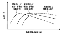
- the horizontal axis indicates the total number of refrigerant paths of the heat exchanger 3, and the vertical axis indicates the energy consumption efficiency COP of the air conditioner 100.
- the heat exchanger 3-3A provided in the outdoor unit 100A will be described as an example, but the heat exchanger according to each embodiment of the present invention may be applied to the heat exchanger 7 of the indoor unit 100B. Is possible.
- the refrigerant path refers to a fin plate in each row in the heat exchanger 3 including a plurality of rows of fin plates 11A, 11B,...
- coolant flow path which connects 11A, 11B, ....
- the number of the refrigerant flow paths independent of the number of paths that is, the number of independent refrigerant paths communicating with the fin plates 11A, 11B,. That is, N paths (N is a natural number) means that N independent communication paths are provided in each row of fin plates 11A, 11B,.
- the path arrangement refers to the arrangement state of the refrigerant paths in the entire heat exchanger 3.
- the indoor and outdoor heat exchangers 3 are respectively used during cooling operation and heating operation. It functions as a condenser or as an evaporator.
- the heat transfer tube used for the refrigerant flow path of the heat exchanger 3 usually has a thin tube shape.
- Each refrigerant path communicates with the internal fin plates 11A, 11B,... Constituting the heat exchanger 3 (see also FIG. 3).
- the heat exchanger 3 functions as an evaporator, the number of passes is increased for the purpose of reducing the flow resistance by reducing the refrigerant flow rate, and when functioning as a condenser, the refrigerant flow rate is increased. Reduce the number of passes to secure the flow rate.
- the heat exchanger 3 functions as a condenser
- the density of the refrigerant is larger than when the heat exchanger 3 functions as an evaporator. For this reason, the refrigerant flow rate becomes slow (at this time, the pressure loss becomes small). Further, at the time of low load, the amount of refrigerant flowing through the condenser becomes smaller than that at the time of high load.
- the number of refrigerant paths is preferably smaller than that when the heat exchanger 3 functions as an evaporator in order to increase the flow velocity of the refrigerant flowing in the heat transfer tube.
- the efficiency of the heat exchanger 3 is maximized, and the energy consumption efficiency COP of the air conditioner 100 is also maximized (see the broken line in FIG. 2).
- the heat exchanger 3 functions as an evaporator, it is desirable to have a larger number of refrigerant paths than when functioning as a condenser in order to reduce the flow velocity of the refrigerant flowing in the heat transfer tube. At this time, the efficiency of the heat exchanger 3 is maximized, and the energy consumption efficiency COP of the air conditioner 100 is also maximized (see the one-dot chain line in FIG. 2).
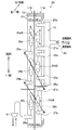
- the heat exchanger 3A is, for example, a cross fin tube type heat exchanger 3, and includes fin plates 11A and 11B in which a plurality of aluminum fins 10 are arranged in the thickness direction, and a refrigerant pipe 20.
- symbol 20 generically refers to all the heat exchanger tubes mentioned later.
- the refrigerant pipe 20 that is visible on the front side (left side in FIG. 3) is drawn with a thick pipe shape
- the invisible refrigerant pipe 20 that is located on the back side (right side in FIG. 3) is drawn with a broken line.
- the refrigerant pipe 20 constitutes a flow path through which the refrigerant flows, and has a shape that penetrates the fins 10 (the fin plates 11A and 11B) in the depth direction in FIG. 3, that is, in the left-right direction in FIG. Yes. That is, the refrigerant pipe 20 extends in a substantially horizontal direction (a direction orthogonal to the vertical direction, the left-right direction in FIG. 3). Then, it is a substantially U-shaped connecting flow path, and again extends in a substantially horizontal direction (a direction perpendicular to the vertical direction, the left-right direction in FIG. 3) via return bends 31a to 33c that reverse the flow direction. Presents. In summary, the refrigerant pipe 20 is disposed so as to meander or reciprocate in the U shape in the fin plates 11A and 11B.
- the refrigerant pipe 20 includes a header 12 to which at least four heat transfer tubes 20a, 21a, 22a, and 23a are connected, and is connected to one end (the left end in FIG. 3) of the fin plate 11A.
- the header 12 functions as a distributor when the heat exchanger 30 functions as a condenser, and functions as a merger when the heat exchanger 30 functions as an evaporator.
- the heat transfer tube 20a extends from the header 12 to the fin plate 11A, and then penetrates the fin plate 11A from one end side to the other end side in the left-right direction in FIG. 3 (front to back direction in FIG. 3). And it connects with the other end side when the lower side of return bend 31a is made into one end side, ie, the upper side of return bend 31a.
- the fin plate 11A penetrates the fin plate 11A from one end side to the other end side in the left-right direction in FIG. 3 (front to back direction in FIG. 3), and the return bend 31b. Is connected to the lower end of the return bend 31b.
- the branch / merging portion 24a has, for example, a three-pronged shape and is disposed between the heat transfer tube 20a and the heat transfer tube 21a. Then, two of the three-pronged shapes respectively penetrate the fin plate 11A from the one end side to the other end side in the left-right direction in FIG. 3 (front to back direction in FIG. 3). 3 are connected to one end side and the other end side of the return bends 31a and 31b on the right side in FIG. Further, the remaining one of the three-forked shape of the branching / merging portion 24a penetrates the fin plate 11B from one end side to the other end side in the left-right direction in FIG. 3 (front to back direction in FIG. 3). And it is connected with the one end side of the return bend 31c in the right side of FIG. 3, ie, the paper surface back
- the heat transfer tube 25a has a substantially U shape, and the two heat transfer tubes disposed on the lower side (one end side) and the upper side (the other end side) in the side view shown in FIG. From one end side to the other end side, it penetrates in the left-right direction in FIG. 3 (front side-back direction in FIG. 3). Then, one end side is connected to the return bend 31c and the other end side is connected to the return bend 31d on the right side of FIG.
- the heat transfer tube 26a passes through the fin plate 11B from one end side to the other end side in the left-right direction in FIG. 3 (front side to back direction in FIG. 3), and returns on the right side in FIG. 3, that is, on the back side in FIG.
- the other end of the bend 31d is connected.
- the heat transfer tube 22a passes through the fin plate 11A from one end side to the other end side in the left-right direction in FIG. 3 (front to back direction in FIG. 3), and on the right side in FIG. 3, that is, the back side in FIG. And connected to the other end of the return bend 32a.
- the heat transfer tube 23a penetrates the fin plate 11A from one end side to the other end side in the left-right direction in FIG. 3 (front side to back direction in FIG. 3), and returns on the right side in FIG. 3, that is, on the back side in FIG. It is connected to one end of the bend 32b.
- the branch junction 24b has, for example, a three-pronged shape, and is positioned between the heat transfer tube 22a and the heat transfer tube 23a, two of which penetrate the fin plate 11A from one end side to the other end side to return bend 32a. 32b are connected to one end side and the other end side, respectively. The remaining branching junction 24b passes through the fin plate 11B from one end side to the other end side and is connected to one end side of the return bend 32c.
- the heat transfer tube 25b has a substantially U shape, and the two heat transfer tubes disposed on the lower side (one end side) and the upper side (the other end side) in the side view shown in FIG. From one end side to the other end side, it penetrates in the left-right direction in FIG. 3 (front side-back direction in FIG. 3). Then, one end side is connected to the return bend 32c and the other end side is connected to the return bend 32d on the right side of FIG.
- the heat transfer tube 27a is located below the heat transfer tube 23a, penetrates the fine plate 11A from one end side to the other end side, and is connected to the other end side of the return bend 33a.
- the heat transfer tube 27b is located below the heat transfer tube 27a, penetrates the fin plate 11A from one end side to the other end side, and is connected to one end side of the return bend 33b.
- the branching / merging portion 24c has, for example, a three-pronged shape, and is located between the heat transfer tube 27a and the heat transfer tube 27b, two of which penetrate the fin plate 11A from one end side to the other end side, and each return bend. It is connected to one end side and the other end side of 33a, 33b.
- the remaining branching junction 24c passes through the fin plate 11B from one end side to the other end side and is connected to one end side of the return bend 33c.
- the heat transfer tube 25c has a substantially U shape, and the two heat transfer tubes arranged on the lower side (one end side) and the upper side (the other end side) in the side view shown in FIG. From one end side to the other end side, it penetrates in the left-right direction in FIG. 3 (front side-back direction in FIG. 3). Then, one end side is connected to the return bend 33c on the right side of FIG. 3, that is, the back side of the sheet of FIG. 3, and the other end side is connected to the return bend 33d.
- the heat transfer tubes 26a and 27a are connected via a connecting tube 35a (see FIG. 3).
- the heat transfer tube 26b and the heat transfer tube 27b are connected via a connecting tube 35b.
- the refrigerant path of the heat exchanger 3 is the heat exchanger 3 including a plurality of rows of fin plates 11A, 11B,. It is a path (passage) communicating the fin plates 11A, 11B,.
- the number of refrigerant paths in the present embodiment means the number of independent refrigerant paths. That is, in the present embodiment, the number of refrigerant paths refers to the number of flow paths in which one end of the refrigerant flow path 20 communicates with the fin plates 11A, 11B,. It matches.
- the fin plates 11A and 11B in each row are arranged via a flow path including any one of the heat transfer tubes 20a to 23a, the branch merging portions 24a to 24c, or the connecting pipes 35a and 35b. ,... are consistent with the number of flow paths communicating with each other. That is, in the present embodiment, when the number of refrigerant paths is counted, the number of the heat transfer tubes 20a to 23a, the branch merging portions 24a to 24c, or the connecting pipes 35a and 35b may be counted for convenience of explanation.
- the refrigerant flowing into the header 12 of the heat exchanger 3A functioning as a condenser from the gate 40 side flows from the N path (N is a natural number) in the process of flowing through the refrigerant path of the refrigerant pipe 20. Finally, it merges into one path and flows into the expansion valve 5 (see FIG. 1) from the gate 41 side.
- the refrigerant that has flowed into the heat transfer pipe 28a of the heat exchanger 3A functioning as an evaporator from the gate 41 side finally flows from one pass through the refrigerant path of the refrigerant pipe 20.
- N is a natural number
- the heat exchanger 3A includes the upper first heat exchanging region HE1a and the upper second heat exchanging region HE1b that are divided in the rows and the vertical direction of the fin plates 11A and 11B.
- the heat exchanger 3A includes the upper first heat exchanging region HE1a and the upper second heat exchanging region HE1b that are divided in the rows and the vertical direction of the fin plates 11A and 11B.
- the plurality of rows of fin plates 11A and 11B have at least four heat exchange region HE1a to HE2b.
- the upper first heat exchange part region HE1a is an upper heat exchange part region in the fin plate 11A where the heat transfer tubes 20a to 23a communicating with the header 12 are arranged.
- the lower first heat exchange part region HE2a includes a heat transfer tube 27a to which the lower region, that is, the connecting pipe 35a, is connected to the lower part of the fin plate 11A than the heat transfer tube 23a arranged at the lowest position communicating with the header 12. It is the lower heat exchange area.
- region HE1b contains the position where the branch confluence
- the lower second heat exchanging region HE2b is a lower heat exchanging region than the branching / merging portion 24b disposed at the lowermost position of the first branching / merging portions 24a and 24b in the fin plate 11B. . Or it is the heat exchange part area
- the refrigerant flows out of the upper first heat exchange section HE1a and the refrigerant flows into the upper second heat exchange section HE1b among the four heat exchange section regions HE1a to HE2b.
- Branch junctions 24a and 24b are arranged at the locations.
- the heat exchanger 3A includes branching junctions 24a and 24b on the upstream side of the connecting pipes 35a and 35b.
- the branching junction 24c is arranged at a location where the refrigerant flows out from the lower first heat exchange section region HE2a and the refrigerant flows into the lower second heat exchange section region HE2b. That is, the heat exchanger 3A includes a branching / merging portion 24c on the downstream side of the connecting pipes 35a and 35b.
- connecting pipes 35a and 35b are installed at locations where the refrigerant flows out from the upper second heat exchange section region HE1b and the refrigerant flows into the lower first heat exchange section region HE2a. That is, in the heat exchanger 3A, when the refrigerant flows from one heat exchange part region HE1a to HE2b into the other heat exchange part region HE1a to HE2b, the flow path passing through the branch junction part 24a to 24c and the branch junction part 24a It can be said that it has a flow path that does not pass through 24c. In addition, the flow path that does not pass through the branch merging portions 24a to 24c is specifically a flow path that passes through the connecting pipes 35a and 35b.
- the heat exchanger 3A allows the boundary between the fin plates 11A, 11B in each row and the upper / lower boundary. Each time, the number of passes of the refrigerant pipe 20 can be changed.
- the path arrangement of the heat exchanger 3A is, for example, four paths of the heat transfer tubes 20a to 23a on the inlet side to the upper first heat exchange section region HE1a when functioning as a condenser.
- the path arrangement is such that the number of paths gradually decreases from the entrance side to the exit side: 4 passes ⁇ 2 passes ⁇ 1 pass ⁇ 1 pass.
- the heat exchanger 3A is the heat exchangers 3 and 7 of the fin plate type 11A, 11B,... Used for the outdoor unit 100A of the air conditioner 100 or the indoor unit 100B. It is.
- a gas side port (gate 40) connected to a pipe through which gaseous refrigerant flows
- a liquid side port (gate 41) connected to a pipe through which liquid refrigerant flows
- At least four heat exchanging region HE1a to HE2b for exchanging heat between the air and the refrigerant flowing through the refrigerant path and the refrigerant path are branched and joined, and the heat exchanging region HE1a to HE2b is passed through the refrigerant path to gas.
- a branch junction 24 (24a to 24c) connected in series is provided between the side port (gate 40) and the liquid side port (gate 41).
- the number of refrigerant paths (heat transfer tubes 20a to 23a) that the heat exchange section HE1a closest to the gas side opening (gate 40) has is the heat exchange section area HE2b closest to the liquid side opening (gate 41).
- the heat exchange region HE1a to HE2b are connected to each other by the branch junction 24 so that the number of refrigerant paths (heat transfer tubes 28a) is larger.
- the heat exchange region HE1a closest to the gas side port (gate 40) is provided above the heat exchange region HE2b closest to the liquid side port (gate 41).
- the heat exchanger 3A functions as a condenser
- the refrigerant flows from one heat exchange region HE1a to another heat exchange region HE1b in the heat exchange regions HE1a to HE2b
- branching / merging portions 24a to 24c whose number is reduced.
- the refrigerant flowing through the refrigerant pipe 20 of the heat exchanger 3A flows from one heat exchanging region HE1a of the upper heat exchanging region HE1 and then other heat exchanging units of the adjacent upper heat exchanging region HE1.
- the region HE1b flows, and further flows into one heat exchanging region HE2a of the lower heat exchanging region HE2 via the connecting pipes 35a and 35b, and another heat exchanging region HE2b of the adjacent lower heat exchanging region HE2 passes through the region HE1b. It flows and flows out.
- the heat exchanger 3A functions as an evaporator, the same can be said as in the case of the condenser described above.
- branch junctions 24a to 24c that increase the number of refrigerant paths are provided. It can be said that it is equipped.
- the refrigerant generally causes a phase transition between the gas phase and the liquid phase inside the heat exchanger 3A. Since the gas phase has a smaller density than the liquid phase even at the same mass flow rate, the flow rate of the gas phase refrigerant is about 10 times or more faster than the flow rate of the liquid phase refrigerant. As a result, in the region where the gas phase is dominant, the heat exchange efficiency is likely to be lowered due to an increase in pressure loss due to an increase in flow velocity. Further, in the region where the liquid phase is dominant, the heat exchange efficiency is lowered due to the decrease in the flow velocity, and thus the heat exchange efficiency is easily lowered.
- the heat exchanger 3A functions as a condenser
- the above-described path arrangement in which the number of passes is irregularly decreased is used, so that the number of passes is increased in a region where the gas-phase refrigerant is dominant, thereby increasing the flow velocity. And increase in pressure loss can be prevented.
- the number of passes is reduced to one on the outlet side with respect to the four passes on the inlet side, that is, the number of passes is reduced to 1 ⁇ 4 to increase the flow velocity, thereby improving the heat transfer coefficient. be able to.
- the outlet side at the time of evaporator (outlet side at the time of condenser) and the outlet side at the time of evaporator (inlet side at the time of condenser) with respect to one pass.
- the number of passes can be quadrupled, such as 4 passes.
- the branching / merging portions are respectively provided at locations where the heat transfer tubes are transferred to the fin plates of the heat exchanger 16 or the heat exchanger 18. For this reason, for example, in order to perform branching and merging twice, three or more rows of heat exchangers are provided. As a result, there is a problem that the installation space for the heat exchanger is enlarged.
- the branch and merge sections 24a to 24c are connected to the upper heat exchange section region HE1 by connecting the connecting pipes 35a and 35b so as to be slanted in the vertical direction. It can arrange
- the ratio of the heat transfer tubes 20a to 23a serving as the refrigerant paths flowing into the first branch and merge sections 24a and 24b in the vertical direction of the heat exchanger 3A is the refrigerant path flowing out from the second branch and merge section 24c.
- the length in the vertical direction of the region HE2b ".
- the heat exchange part regions HE1a to HE2b are divided into at least an upper heat exchange part region HE1 and a lower heat exchange part region HE2, and the length of the upper heat exchange part region HE1 in the vertical direction is defined as the lower heat exchange part region HE1. It can be said that it is longer than the vertical length of HE2.
- the number of passes in the region in which the gas phase flowing into the first branch / merging portions 24a, 24b is dominant can be increased. That is, four or more heat transfer tubes 20a to 23a can be easily installed. In this way, the pressure loss can be reduced particularly when the heat exchanger 3A functions as an evaporator.
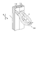
- FIG. 4 is an enlarged perspective view of branching junctions 24a to 24c (generically denoted by reference numeral 24) of the heat exchanger 3A according to the first embodiment.
- the trifurcated shape of the branch merging portions 24a to 24c of the heat exchanger 3A has a shape in which the refrigerant merges in the direction orthogonal to the flow paths RP and SP at the merging point P and is discharged.
- the vertical position of the point Q where the refrigerant flows into the fin plate 11B is the height of the intermediate position of the line segment connecting the points R and S.
- the trifurcated portions of the branching / merging portions 24a to 24c can be made of a material that has a small number of bending portions and can be easily processed. For this reason, it is possible to prevent an increase in manufacturing cost of the branch merging portions 24a to 24c.
- the heat exchanger 3A includes a plurality of rows of fin plates 11A and 11B.
- the refrigerant path is defined as a refrigerant flow path (communication path) that connects the fin plates 11A and 11B in each row.
- the heat exchanger 3A includes at least four refrigerant paths 20a to 23a in the vertical direction in which the refrigerant flows in during the condenser and flows out during the evaporator.
- the heat exchanger 3A functions as a condenser, for example, the heat exchanger region HE1a to HE2b of the heat exchanger 3A divided into at least four parts from one heat exchange region to another heat exchange region Branching / merging portions 24a to 24c are provided that reduce the number of paths when the refrigerant flows into the.
- the number of passes on the outlet side at the time of the evaporator (outlet side at the time of the condenser) relative to the inlet side at the time of evaporator (outlet side at the time of the condenser) can be at least quadrupled. Thereby, it is possible to prevent the pressure loss from increasing in a region where the gas-phase refrigerant is dominant.
- the connecting pipes 35a and 35b are obliquely connected in the vertical direction so as to connect the upper heat exchange region HE1 and the lower heat exchange region HE2. ing. Accordingly, the branching junctions 24a to 24c can be arranged at appropriate positions in the upper heat exchange region HE1 and the lower heat exchange region HE2, respectively. Thereby, the required number of rows of the fin plates 11A, 11B,... Of the heat exchanger 3A can be reduced, and the installation space of the heat exchanger 3A can be saved.
- the heat exchanger 3A has “the length in the vertical direction of the upper first heat exchange region HE1a> the length in the vertical direction of the lower second heat exchange region HE2b”. As a result, it is possible to easily install four or more paths in the region where the gas phase flowing into the first branch / merging section 24a, 24b is dominant, specifically, the number of the heat transfer tubes 20a to 23a. If it does in this way, when heat exchanger 3A functions especially as an evaporator, pressure loss can be reduced and heat exchange efficiency can be improved.
- the heat exchange part region HE1a closest to the gas side port (gate 40) is provided above the heat exchange part region HE2b closest to the liquid side port (gate 41). That is, the upper first heat exchanging region HE1a in which the gas-phase refrigerant is dominant is provided above the lower second heat exchanging region HE2b in which the liquid-phase refrigerant is dominant.
- coolant receives to the influence of gravity, and it is easy to gather in lower 2nd heat exchange part area
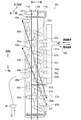
- FIG. 5 is a schematic diagram illustrating a refrigerant path of the heat exchanger 3B according to the second embodiment.
- FIG. 6 is an enlarged perspective view of a branching / merging portion of the heat exchanger 3B according to the second embodiment.
- FIG. 5 is a diagram corresponding to FIG. 3 of the first embodiment.
- symbol is attached
- the height position in the vertical direction of the point Q where the refrigerant flows into the fin plate 11B out of the three-pronged shape of the branch merging portions 24a to 24c is the point R, It was made equal to the height of the middle position of the line segment which connects S (refer FIG. 4).
- the heat exchanger 3B of the second embodiment is as follows as compared with the heat exchanger 3A of the first embodiment. There are differences.
- the vertical position of the point Q where the refrigerant flows into the fin plate 11B is, for example, the vertical height of the point R It is designed to be higher than the position by a distance T. That is, the heat transfer tube between the flow paths PQ is formed so as to be twisted upward from the middle of the flow path.
- branching junctions 24aB to 24cB are used, for example, as shown in FIG. 5, the position of the hole at the point Q is shifted upward to avoid the heat transfer tubes 25a to 25c of the fin plate 11B. This is also preferable because the branch junctions 24aB to 24cB can be installed.
- the present invention is not particularly limited thereto, and the hole may be formed shifted downward. Further, the size of the distance T (see FIG. 6) is not particularly limited.
- the heat exchanger 3B is the heat exchangers 3 and 7 of the fin plate type 11A, 11B,... Used for the outdoor unit 100A of the air conditioner 100 or the indoor unit 100B.
- a gas side port (gate 40) connected to a pipe through which gaseous refrigerant flows
- a liquid side port (gate 41) connected to a pipe through which liquid refrigerant flows
- a gas side port A refrigerant path connecting the mouth and the liquid side mouth.
- At least four heat exchanging region HE1a to HE2b for exchanging heat between the air and the refrigerant flowing through the refrigerant path and the refrigerant path are branched and joined, and the heat exchanging region HE1a to HE2b is passed through the refrigerant path to gas.
- a branch junction 24B (24aB to 24cB) connected in series is provided between the side port (gate 40) and the liquid side port (gate 41).
- the number of refrigerant paths (heat transfer tubes 20a to 23a) that the heat exchange section HE1a closest to the gas side opening (gate 40) has is the heat exchange section area HE2b closest to the liquid side opening (gate 41).
- the heat exchange regions HE1a to HE2b are connected to each other by branch junctions 24B (24aB to 24cB) so as to be larger than the number of refrigerant paths (heat transfer tubes 28a).
- the heat exchange region HE1a closest to the gas side port (gate 40) is provided above the heat exchange region HE2b closest to the liquid side port (gate 41).
- FIG. 7 is a schematic diagram for explaining a refrigerant path of the heat exchanger 3C according to the third embodiment.
- FIG. 7 is a diagram corresponding to FIG. 3 of the first embodiment.
- symbol is attached
- the fin plates 11A and 11B have been described as having two rows.
- the fin plates are not limited to two rows, and the heat exchanger 3C according to the third embodiment is different in that it includes three rows of fin plates 11A, 11B, and 11C.
- heat transfer tubes 37a to 37f serving as refrigerant paths are installed at the boundary portions of the fin plates 11A and 11B (FIG. 7). And FIG. 3 for comparison).
- Other parts are the same as in the first embodiment.
- the upper heat exchange part region HE1 is a region including the upper first heat exchange part region HE1a, the upper second heat exchange part region HE1b, and the upper third heat exchange part region HE1c.
- region HE1b are the part beyond this including the heat exchanger tube 37d among fin plate 11A, 11B.
- the upper third heat exchanging region HE1c is a further portion including the branching junction 24b in the fin plate 11C.
- the lower heat exchange part region HE2 is a region including a lower first heat exchange part region HE2a, a lower second heat exchange part region HE2b, and a lower third heat exchange part region HE2c.
- region HE2b are parts below the heat exchanger tube 37d among fin plate 11A, 11B.
- the lower third heat exchange part region HE2c is a part of the fin plate 11C that is lower than the branch junction part 24b.
- the number of the heat transfer tubes 20a to 23a, the branch merging portions 24a to 24c, the connecting pipes 35a and 35b, and the heat transfer pipes 37a to 37f are the same as in the first embodiment. Should be counted.
- the locations where the heat transfer tubes 37a to 37f serving as refrigerant paths are installed are not particularly limited to the boundary portions of the fin plates 11A and 11B, and are configured to be installed at the boundary portions of the fin plates 11B and 11C. Also good.
- the branching / merging portions 24a to 24c may be installed at the boundary portions of the fin plates 11A and 11B. That is, the arrangement order of the heat transfer tubes 37a to 37f and the branching / merging portions 24a to 24c can be changed in the thickness direction before and after the heat exchanger 3C (left and right direction in FIG. 7).
- the heat exchanger 3C according to the third embodiment is configured such that the branch merging portions 24a to 24c are moved once in the upper heat exchanging portion region HE1 (branch merging portions 24a and 24b), and the lower heat It will be provided once (branch / merging part 24c) in the exchange part region HE2. That is, in the heat exchanger 3C, the branching / merging portions 24a to 24c are provided twice in total between the fin plates 11A and 11B or between 11B and 11C.
- the path arrangement places importance on reducing the pressure loss in the heat exchanger 3C during the heating operation. That is, with such a heat exchanger 3C, it is possible to make the specification more suitable for use exclusively for heating operation than the known three-row type heat exchanger described in Patent Document 2.
- this is a path arrangement that places importance on increasing the flow rate in the heat exchanger 3C during the cooling operation and improving the heat transfer coefficient. That is, with such a heat exchanger 3C, it is possible to make the specification more suitable for use exclusively for cooling operation than the known three-row type heat exchanger described in Patent Document 2.
- the heat exchanger 3C is the heat exchangers 3 and 7 of the fin plate type 11A, 11B,... Used for the outdoor unit 100A of the air conditioner 100 or the indoor unit 100B.
- a gas side port (gate 40) connected to a pipe through which gaseous refrigerant flows
- a liquid side port (gate 41) connected to a pipe through which liquid refrigerant flows
- a gas side port A refrigerant path connecting the mouth and the liquid side mouth.
- At least four heat exchanging region HE1a to HE2c for exchanging heat between the air and the refrigerant flowing through the refrigerant path and the refrigerant path are branched and merged, and the heat exchanging region HE1a to HE2c is passed through the refrigerant path to gas.
- a branch junction 24 (24a to 24c) connected in series is provided between the side port (gate 40) and the liquid side port (gate 41). Then, the number of refrigerant paths (heat transfer tubes 20a to 23a) that the heat exchange section region HE1a closest to the gas side port (gate 40) has is the heat exchange section region HE2c closest to the liquid side port (gate 41).
- the heat exchange region HE1a to HE2c are connected by the branching junction 24 so that the number of refrigerant paths (heat transfer tubes 28a) is larger. Further, the heat exchange part region HE1a closest to the gas side port (gate 40) is provided above the heat exchange part region HE2c closest to the liquid side port (gate 41).
- the heat exchanger 3C includes a flow path that passes through the branch merging portions 24a to 24c and a branch merging portion 24a when the refrigerant flows from one heat exchanging portion region HE1a to HE2c into the other heat exchanging portion regions HE1a to HE2c. It can be said that it has a flow path that does not pass through 24c.
- the flow path that does not pass through the branch / merging portions 24a to 24c is specifically a flow path that passes through the connecting pipes 35a and 35b and the heat transfer pipes 37a to 37f.
- a part of the configuration of one embodiment can be replaced with the configuration of another embodiment, and a part or all of the configuration of another embodiment can be added to the configuration of one embodiment. It is. In addition, it is possible to add, delete, and replace other configurations for a part of the configuration of each embodiment.
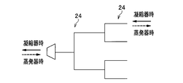
- FIG. 8 is a diagram schematically illustrating the refrigerant flow path of the heat exchanger according to the first to third embodiments.
- FIG. 8 and FIG. 9 to be described later all the portions where the flow path is bent other than the branch / merging portion 24 are represented by straight lines.
- FIG. 9 is a diagram schematically illustrating the refrigerant flow path of the heat exchanger according to the modification.
- the branching / merging portion 24 may have an N-fork shape, that is, an N-branching / merging portion 24N.
- the schematic diagram of the refrigerant flow path may have a substantially pyramid shape in which a plurality of branching / merging portions 24N are connected in series.
- the schematic diagram of the refrigerant flow path may have a shape in which N-forked branched junctions 24N are arranged in N steps in a stepped manner.
- an N-forked branch / merging section 24N is used in the first stage, and a trifurcated branch / merging section 24 (any one of the branch / merging sections 24a to 24c and 24aB to 24cB) is used in the second stage. That is, FIG. 9 illustrates the case of a two-stage shape.
- branching / merging portions 24a to 24c In the third embodiment, the case where the branching / merging portions 24a to 24c are used has been described. However, the branching / merging portions 24aB to 24cB in the second embodiment may be used instead of the branching / merging portions 24a to 24c.
- the modification example in which the branch junctions 24a to 24c of both the upper heat exchange part region HE1 and the lower heat exchange part region HE2 are moved to the boundary portions of the fin plates 11A and 11B has been described.
- the configuration may be such that only the branching / merging portions 24a, 24b in the upper heat exchanging portion region HE1 or the branching / merging portion 24c in the lower heat exchanging portion region HE2 are moved to the boundary portions of the fin plates 11A, 11B. That is, the branching / merging portions 24a to 24c may be arranged between the different fin plates 11A, 11B,... Via the connecting pipes 35a and 35b.
Landscapes
- Engineering & Computer Science (AREA)
- Physics & Mathematics (AREA)
- Thermal Sciences (AREA)
- Mechanical Engineering (AREA)
- General Engineering & Computer Science (AREA)
- Heat-Exchange Devices With Radiators And Conduit Assemblies (AREA)
Priority Applications (5)
| Application Number | Priority Date | Filing Date | Title |
|---|---|---|---|
| EP15903602.9A EP3348935B1 (en) | 2015-09-10 | 2015-09-10 | Heat exchanger |
| JP2017538801A JP6671380B2 (ja) | 2015-09-10 | 2015-09-10 | 熱交換器 |
| PCT/JP2015/075752 WO2017042940A1 (ja) | 2015-09-10 | 2015-09-10 | 熱交換器 |
| US15/758,416 US10907902B2 (en) | 2015-09-10 | 2015-09-10 | Heat exchanger |
| CN201580083019.XA CN108027181B (zh) | 2015-09-10 | 2015-09-10 | 热交换器 |
Applications Claiming Priority (1)
| Application Number | Priority Date | Filing Date | Title |
|---|---|---|---|
| PCT/JP2015/075752 WO2017042940A1 (ja) | 2015-09-10 | 2015-09-10 | 熱交換器 |
Publications (1)
| Publication Number | Publication Date |
|---|---|
| WO2017042940A1 true WO2017042940A1 (ja) | 2017-03-16 |
Family
ID=58239341
Family Applications (1)
| Application Number | Title | Priority Date | Filing Date |
|---|---|---|---|
| PCT/JP2015/075752 WO2017042940A1 (ja) | 2015-09-10 | 2015-09-10 | 熱交換器 |
Country Status (5)
| Country | Link |
|---|---|
| US (1) | US10907902B2 (zh) |
| EP (1) | EP3348935B1 (zh) |
| JP (1) | JP6671380B2 (zh) |
| CN (1) | CN108027181B (zh) |
| WO (1) | WO2017042940A1 (zh) |
Cited By (1)
| Publication number | Priority date | Publication date | Assignee | Title |
|---|---|---|---|---|
| JPWO2019142296A1 (ja) * | 2018-01-18 | 2020-12-17 | 三菱電機株式会社 | 熱交換器、室外ユニットおよび冷凍サイクル装置 |
Families Citing this family (1)
| Publication number | Priority date | Publication date | Assignee | Title |
|---|---|---|---|---|
| KR20200116848A (ko) * | 2019-04-02 | 2020-10-13 | 엘지전자 주식회사 | 실외열교환기 및 이를 포함하는 공기조화기 |
Citations (6)
| Publication number | Priority date | Publication date | Assignee | Title |
|---|---|---|---|---|
| US5076353A (en) * | 1989-06-06 | 1991-12-31 | Thermal-Werke Warme, Kalte-, Klimatechnik GmbH | Liquefier for the coolant in a vehicle air-conditioning system |
| JP2001066017A (ja) * | 1999-08-27 | 2001-03-16 | Hitachi Ltd | 空気調和機 |
| US6382310B1 (en) * | 2000-08-15 | 2002-05-07 | American Standard International Inc. | Stepped heat exchanger coils |
| JP2012237543A (ja) * | 2011-04-25 | 2012-12-06 | Panasonic Corp | 冷凍サイクル装置 |
| WO2013084508A1 (ja) * | 2011-12-07 | 2013-06-13 | パナソニック株式会社 | フィンチューブ型熱交換器 |
| JP2015140990A (ja) * | 2014-01-29 | 2015-08-03 | 日立アプライアンス株式会社 | 空気調和機 |
Family Cites Families (5)
| Publication number | Priority date | Publication date | Assignee | Title |
|---|---|---|---|---|
| JP2000304380A (ja) * | 1999-04-22 | 2000-11-02 | Aisin Seiki Co Ltd | 熱交換器 |
| JP4922669B2 (ja) | 2006-06-09 | 2012-04-25 | 日立アプライアンス株式会社 | 空気調和機及び空気調和機の熱交換器 |
| KR101157799B1 (ko) * | 2007-11-30 | 2012-06-20 | 다이킨 고교 가부시키가이샤 | 냉동 장치 |
| CN102460026B (zh) * | 2009-06-19 | 2014-05-07 | 大金工业株式会社 | 天花板嵌入式空调装置 |
| JP5578178B2 (ja) * | 2009-10-22 | 2014-08-27 | ダイキン工業株式会社 | 空気調和機 |
-
2015
- 2015-09-10 US US15/758,416 patent/US10907902B2/en active Active
- 2015-09-10 JP JP2017538801A patent/JP6671380B2/ja active Active
- 2015-09-10 CN CN201580083019.XA patent/CN108027181B/zh active Active
- 2015-09-10 WO PCT/JP2015/075752 patent/WO2017042940A1/ja active Application Filing
- 2015-09-10 EP EP15903602.9A patent/EP3348935B1/en active Active
Patent Citations (6)
| Publication number | Priority date | Publication date | Assignee | Title |
|---|---|---|---|---|
| US5076353A (en) * | 1989-06-06 | 1991-12-31 | Thermal-Werke Warme, Kalte-, Klimatechnik GmbH | Liquefier for the coolant in a vehicle air-conditioning system |
| JP2001066017A (ja) * | 1999-08-27 | 2001-03-16 | Hitachi Ltd | 空気調和機 |
| US6382310B1 (en) * | 2000-08-15 | 2002-05-07 | American Standard International Inc. | Stepped heat exchanger coils |
| JP2012237543A (ja) * | 2011-04-25 | 2012-12-06 | Panasonic Corp | 冷凍サイクル装置 |
| WO2013084508A1 (ja) * | 2011-12-07 | 2013-06-13 | パナソニック株式会社 | フィンチューブ型熱交換器 |
| JP2015140990A (ja) * | 2014-01-29 | 2015-08-03 | 日立アプライアンス株式会社 | 空気調和機 |
Cited By (1)
| Publication number | Priority date | Publication date | Assignee | Title |
|---|---|---|---|---|
| JPWO2019142296A1 (ja) * | 2018-01-18 | 2020-12-17 | 三菱電機株式会社 | 熱交換器、室外ユニットおよび冷凍サイクル装置 |
Also Published As
| Publication number | Publication date |
|---|---|
| CN108027181B (zh) | 2020-09-04 |
| US20180259265A1 (en) | 2018-09-13 |
| EP3348935A1 (en) | 2018-07-18 |
| US10907902B2 (en) | 2021-02-02 |
| JP6671380B2 (ja) | 2020-03-25 |
| EP3348935A4 (en) | 2019-06-12 |
| CN108027181A (zh) | 2018-05-11 |
| JPWO2017042940A1 (ja) | 2018-07-12 |
| EP3348935B1 (en) | 2021-01-27 |
Similar Documents
| Publication | Publication Date | Title |
|---|---|---|
| JP5927415B2 (ja) | 冷凍サイクル装置 | |
| CN112204312B (zh) | 空气调节装置的室外机及空气调节装置 | |
| JP6364539B2 (ja) | 熱交換装置およびこれを用いた空気調和機 | |
| JP6011009B2 (ja) | 熱交換器および空気調和機 | |
| JP6351494B2 (ja) | 空気調和機 | |
| JP4889011B2 (ja) | 冷暖房空調システム | |
| US10670311B2 (en) | Heat exchanger | |
| JP6878511B2 (ja) | 熱交換器、空気調和装置、室内機および室外機 | |
| EP3062037B1 (en) | Heat exchanger and refrigeration cycle device using said heat exchanger | |
| CN110595111B (zh) | 换热器和多制冷系统空调机组 | |
| JP4845987B2 (ja) | 冷暖房空調システム | |
| WO2017042940A1 (ja) | 熱交換器 | |
| JP6925393B2 (ja) | 空気調和装置の室外機及び空気調和装置 | |
| JP2015014397A (ja) | 熱交換器 | |
| CN113646597B (zh) | 冷冻循环装置 | |
| JP6596541B2 (ja) | 空気調和機 | |
| JP6537868B2 (ja) | 熱交換器 | |
| WO2022172359A1 (ja) | 室外熱交換器および空気調和機 | |
| JP6698196B2 (ja) | 空気調和機 | |
| JP7050538B2 (ja) | 熱交換器および空気調和機 | |
| WO2019142296A1 (ja) | 熱交換器、室外ユニットおよび冷凍サイクル装置 |
Legal Events
| Date | Code | Title | Description |
|---|---|---|---|
| 121 | Ep: the epo has been informed by wipo that ep was designated in this application |
Ref document number: 15903602 Country of ref document: EP Kind code of ref document: A1 |
|
| ENP | Entry into the national phase |
Ref document number: 2017538801 Country of ref document: JP Kind code of ref document: A |
|
| WWE | Wipo information: entry into national phase |
Ref document number: 15758416 Country of ref document: US |
|
| NENP | Non-entry into the national phase |
Ref country code: DE |
|
| WWE | Wipo information: entry into national phase |
Ref document number: 2015903602 Country of ref document: EP |