WO2017042940A1 - 熱交換器 - Google Patents
熱交換器 Download PDFInfo
- Publication number
- WO2017042940A1 WO2017042940A1 PCT/JP2015/075752 JP2015075752W WO2017042940A1 WO 2017042940 A1 WO2017042940 A1 WO 2017042940A1 JP 2015075752 W JP2015075752 W JP 2015075752W WO 2017042940 A1 WO2017042940 A1 WO 2017042940A1
- Authority
- WO
- WIPO (PCT)
- Prior art keywords
- refrigerant
- heat exchanger
- region
- heat
- heat exchange
- Prior art date
Links
Images


Classifications
-
- F—MECHANICAL ENGINEERING; LIGHTING; HEATING; WEAPONS; BLASTING
- F28—HEAT EXCHANGE IN GENERAL
- F28D—HEAT-EXCHANGE APPARATUS, NOT PROVIDED FOR IN ANOTHER SUBCLASS, IN WHICH THE HEAT-EXCHANGE MEDIA DO NOT COME INTO DIRECT CONTACT
- F28D1/00—Heat-exchange apparatus having stationary conduit assemblies for one heat-exchange medium only, the media being in contact with different sides of the conduit wall, in which the other heat-exchange medium is a large body of fluid, e.g. domestic or motor car radiators
- F28D1/02—Heat-exchange apparatus having stationary conduit assemblies for one heat-exchange medium only, the media being in contact with different sides of the conduit wall, in which the other heat-exchange medium is a large body of fluid, e.g. domestic or motor car radiators with heat-exchange conduits immersed in the body of fluid
- F28D1/04—Heat-exchange apparatus having stationary conduit assemblies for one heat-exchange medium only, the media being in contact with different sides of the conduit wall, in which the other heat-exchange medium is a large body of fluid, e.g. domestic or motor car radiators with heat-exchange conduits immersed in the body of fluid with tubular conduits
- F28D1/0408—Multi-circuit heat exchangers, e.g. integrating different heat exchange sections in the same unit or heat exchangers for more than two fluids
- F28D1/0426—Multi-circuit heat exchangers, e.g. integrating different heat exchange sections in the same unit or heat exchangers for more than two fluids with units having particular arrangement relative to the large body of fluid, e.g. with interleaved units or with adjacent heat exchange units in common air flow or with units extending at an angle to each other or with units arranged around a central element
- F28D1/0435—Combination of units extending one behind the other
-
- F—MECHANICAL ENGINEERING; LIGHTING; HEATING; WEAPONS; BLASTING
- F25—REFRIGERATION OR COOLING; COMBINED HEATING AND REFRIGERATION SYSTEMS; HEAT PUMP SYSTEMS; MANUFACTURE OR STORAGE OF ICE; LIQUEFACTION SOLIDIFICATION OF GASES
- F25B—REFRIGERATION MACHINES, PLANTS OR SYSTEMS; COMBINED HEATING AND REFRIGERATION SYSTEMS; HEAT PUMP SYSTEMS
- F25B39/00—Evaporators; Condensers
-
- F—MECHANICAL ENGINEERING; LIGHTING; HEATING; WEAPONS; BLASTING
- F28—HEAT EXCHANGE IN GENERAL
- F28D—HEAT-EXCHANGE APPARATUS, NOT PROVIDED FOR IN ANOTHER SUBCLASS, IN WHICH THE HEAT-EXCHANGE MEDIA DO NOT COME INTO DIRECT CONTACT
- F28D1/00—Heat-exchange apparatus having stationary conduit assemblies for one heat-exchange medium only, the media being in contact with different sides of the conduit wall, in which the other heat-exchange medium is a large body of fluid, e.g. domestic or motor car radiators
- F28D1/02—Heat-exchange apparatus having stationary conduit assemblies for one heat-exchange medium only, the media being in contact with different sides of the conduit wall, in which the other heat-exchange medium is a large body of fluid, e.g. domestic or motor car radiators with heat-exchange conduits immersed in the body of fluid
- F28D1/04—Heat-exchange apparatus having stationary conduit assemblies for one heat-exchange medium only, the media being in contact with different sides of the conduit wall, in which the other heat-exchange medium is a large body of fluid, e.g. domestic or motor car radiators with heat-exchange conduits immersed in the body of fluid with tubular conduits
- F28D1/0408—Multi-circuit heat exchangers, e.g. integrating different heat exchange sections in the same unit or heat exchangers for more than two fluids
- F28D1/0417—Multi-circuit heat exchangers, e.g. integrating different heat exchange sections in the same unit or heat exchangers for more than two fluids with particular circuits for the same heat exchange medium, e.g. with the heat exchange medium flowing through sections having different heat exchange capacities or for heating/cooling the heat exchange medium at different temperatures
-
- F—MECHANICAL ENGINEERING; LIGHTING; HEATING; WEAPONS; BLASTING
- F28—HEAT EXCHANGE IN GENERAL
- F28D—HEAT-EXCHANGE APPARATUS, NOT PROVIDED FOR IN ANOTHER SUBCLASS, IN WHICH THE HEAT-EXCHANGE MEDIA DO NOT COME INTO DIRECT CONTACT
- F28D1/00—Heat-exchange apparatus having stationary conduit assemblies for one heat-exchange medium only, the media being in contact with different sides of the conduit wall, in which the other heat-exchange medium is a large body of fluid, e.g. domestic or motor car radiators
- F28D1/02—Heat-exchange apparatus having stationary conduit assemblies for one heat-exchange medium only, the media being in contact with different sides of the conduit wall, in which the other heat-exchange medium is a large body of fluid, e.g. domestic or motor car radiators with heat-exchange conduits immersed in the body of fluid
- F28D1/04—Heat-exchange apparatus having stationary conduit assemblies for one heat-exchange medium only, the media being in contact with different sides of the conduit wall, in which the other heat-exchange medium is a large body of fluid, e.g. domestic or motor car radiators with heat-exchange conduits immersed in the body of fluid with tubular conduits
- F28D1/047—Heat-exchange apparatus having stationary conduit assemblies for one heat-exchange medium only, the media being in contact with different sides of the conduit wall, in which the other heat-exchange medium is a large body of fluid, e.g. domestic or motor car radiators with heat-exchange conduits immersed in the body of fluid with tubular conduits the conduits being bent, e.g. in a serpentine or zig-zag
- F28D1/0477—Heat-exchange apparatus having stationary conduit assemblies for one heat-exchange medium only, the media being in contact with different sides of the conduit wall, in which the other heat-exchange medium is a large body of fluid, e.g. domestic or motor car radiators with heat-exchange conduits immersed in the body of fluid with tubular conduits the conduits being bent, e.g. in a serpentine or zig-zag the conduits being bent in a serpentine or zig-zag
-
- F—MECHANICAL ENGINEERING; LIGHTING; HEATING; WEAPONS; BLASTING
- F28—HEAT EXCHANGE IN GENERAL
- F28F—DETAILS OF HEAT-EXCHANGE AND HEAT-TRANSFER APPARATUS, OF GENERAL APPLICATION
- F28F9/00—Casings; Header boxes; Auxiliary supports for elements; Auxiliary members within casings
- F28F9/26—Arrangements for connecting different sections of heat-exchange elements, e.g. of radiators
- F28F9/262—Arrangements for connecting different sections of heat-exchange elements, e.g. of radiators for radiators
-
- F—MECHANICAL ENGINEERING; LIGHTING; HEATING; WEAPONS; BLASTING
- F25—REFRIGERATION OR COOLING; COMBINED HEATING AND REFRIGERATION SYSTEMS; HEAT PUMP SYSTEMS; MANUFACTURE OR STORAGE OF ICE; LIQUEFACTION SOLIDIFICATION OF GASES
- F25B—REFRIGERATION MACHINES, PLANTS OR SYSTEMS; COMBINED HEATING AND REFRIGERATION SYSTEMS; HEAT PUMP SYSTEMS
- F25B39/00—Evaporators; Condensers
- F25B39/04—Condensers
-
- F—MECHANICAL ENGINEERING; LIGHTING; HEATING; WEAPONS; BLASTING
- F28—HEAT EXCHANGE IN GENERAL
- F28D—HEAT-EXCHANGE APPARATUS, NOT PROVIDED FOR IN ANOTHER SUBCLASS, IN WHICH THE HEAT-EXCHANGE MEDIA DO NOT COME INTO DIRECT CONTACT
- F28D1/00—Heat-exchange apparatus having stationary conduit assemblies for one heat-exchange medium only, the media being in contact with different sides of the conduit wall, in which the other heat-exchange medium is a large body of fluid, e.g. domestic or motor car radiators
- F28D1/02—Heat-exchange apparatus having stationary conduit assemblies for one heat-exchange medium only, the media being in contact with different sides of the conduit wall, in which the other heat-exchange medium is a large body of fluid, e.g. domestic or motor car radiators with heat-exchange conduits immersed in the body of fluid
- F28D1/04—Heat-exchange apparatus having stationary conduit assemblies for one heat-exchange medium only, the media being in contact with different sides of the conduit wall, in which the other heat-exchange medium is a large body of fluid, e.g. domestic or motor car radiators with heat-exchange conduits immersed in the body of fluid with tubular conduits
- F28D1/047—Heat-exchange apparatus having stationary conduit assemblies for one heat-exchange medium only, the media being in contact with different sides of the conduit wall, in which the other heat-exchange medium is a large body of fluid, e.g. domestic or motor car radiators with heat-exchange conduits immersed in the body of fluid with tubular conduits the conduits being bent, e.g. in a serpentine or zig-zag
- F28D1/0477—Heat-exchange apparatus having stationary conduit assemblies for one heat-exchange medium only, the media being in contact with different sides of the conduit wall, in which the other heat-exchange medium is a large body of fluid, e.g. domestic or motor car radiators with heat-exchange conduits immersed in the body of fluid with tubular conduits the conduits being bent, e.g. in a serpentine or zig-zag the conduits being bent in a serpentine or zig-zag
- F28D1/0478—Heat-exchange apparatus having stationary conduit assemblies for one heat-exchange medium only, the media being in contact with different sides of the conduit wall, in which the other heat-exchange medium is a large body of fluid, e.g. domestic or motor car radiators with heat-exchange conduits immersed in the body of fluid with tubular conduits the conduits being bent, e.g. in a serpentine or zig-zag the conduits being bent in a serpentine or zig-zag the conduits having a non-circular cross-section
-
- F—MECHANICAL ENGINEERING; LIGHTING; HEATING; WEAPONS; BLASTING
- F28—HEAT EXCHANGE IN GENERAL
- F28D—HEAT-EXCHANGE APPARATUS, NOT PROVIDED FOR IN ANOTHER SUBCLASS, IN WHICH THE HEAT-EXCHANGE MEDIA DO NOT COME INTO DIRECT CONTACT
- F28D21/00—Heat-exchange apparatus not covered by any of the groups F28D1/00 - F28D20/00
- F28D2021/0019—Other heat exchangers for particular applications; Heat exchange systems not otherwise provided for
- F28D2021/0068—Other heat exchangers for particular applications; Heat exchange systems not otherwise provided for for refrigerant cycles
-
- F—MECHANICAL ENGINEERING; LIGHTING; HEATING; WEAPONS; BLASTING
- F28—HEAT EXCHANGE IN GENERAL
- F28F—DETAILS OF HEAT-EXCHANGE AND HEAT-TRANSFER APPARATUS, OF GENERAL APPLICATION
- F28F1/00—Tubular elements; Assemblies of tubular elements
- F28F1/10—Tubular elements and assemblies thereof with means for increasing heat-transfer area, e.g. with fins, with projections, with recesses
- F28F1/12—Tubular elements and assemblies thereof with means for increasing heat-transfer area, e.g. with fins, with projections, with recesses the means being only outside the tubular element
- F28F1/24—Tubular elements and assemblies thereof with means for increasing heat-transfer area, e.g. with fins, with projections, with recesses the means being only outside the tubular element and extending transversely
- F28F1/32—Tubular elements and assemblies thereof with means for increasing heat-transfer area, e.g. with fins, with projections, with recesses the means being only outside the tubular element and extending transversely the means having portions engaging further tubular elements
- F28F1/325—Fins with openings
-
- F—MECHANICAL ENGINEERING; LIGHTING; HEATING; WEAPONS; BLASTING
- F28—HEAT EXCHANGE IN GENERAL
- F28F—DETAILS OF HEAT-EXCHANGE AND HEAT-TRANSFER APPARATUS, OF GENERAL APPLICATION
- F28F9/00—Casings; Header boxes; Auxiliary supports for elements; Auxiliary members within casings
- F28F9/26—Arrangements for connecting different sections of heat-exchange elements, e.g. of radiators
- F28F9/262—Arrangements for connecting different sections of heat-exchange elements, e.g. of radiators for radiators
- F28F9/268—Arrangements for connecting different sections of heat-exchange elements, e.g. of radiators for radiators by permanent joints, e.g. by welding
Abstract
Description
このため、熱交換器が凝縮器として用いられる場合と、蒸発器として用いられる場合とにおいて、それぞれ熱交換効率を最大化するのに最適なパス数が存在する。
しかし、分岐合流部は熱交換器のフィンプレートの各列の境界部分に設けられるため、2回合流を行うためには、熱交換器のフィンプレートの列数は3列以上必要となっていた。これによって、熱交換器の設置スペースが拡大してしまうという問題があった。
また、それぞれの分岐合流部は、合流後の次の冷媒パスに連通する伝熱管の上端または下端に位置している。このため、それぞれの分岐合流部において、分岐合流部に流入する各冷媒パスの距離、すなわち冷媒の流路長が等しくなっていなかった。したがって、分岐合流部の三叉形状が非対称となっていた(特許文献2の図1を参照)。
を特徴とする熱交換器とする。
なお、以下では一実施形態にかかわる熱交換器が空気調和機に備えられている場合を例に挙げて説明する。しかし特にこれには限定されず、本発明の一実施形態にかかわる熱交換器は、空気調和機以外の冷凍サイクルを備えたあらゆる冷温熱機器に適用できる。
また、以下で特に断りなく冷媒または冷凍サイクルと言った場合、冷却または加熱、もしくはその両方で使用可能な冷媒または冷凍サイクルを指すものとする。
また、説明の便宜上、各図面で共通する部材には同一の符号を付して、重複する説明を省略する。前後上下左右または一端・他端などの方向軸については、各図の記載によるものとする。
ここで、本発明の一実施形態にかかわる熱交換器を含む空気調和機100は、室外機100Aと室内機100Bとが冷媒配管100V,100Lなどを介して接続され、回路内に冷媒を循環させることで、室内の空調を可能にするものである。
図1は、第1実施形態にかかわる熱交換器3を含む空気調和機100の冷凍サイクルを説明する図である。
図1に示すように、第1実施形態にかかわる空気調和機100は、室外機100Aと、室内機100Bと、室外機100Aと室内機100Bとを接続する冷媒配管100L,100Vとを含んで構成されている。
また、室内機100B(室内ユニット)は、室内機100B側の減圧装置である膨張弁6と、クロスフィンチューブ型の室内の熱交換器7、および当該熱交換器7へ空気を送り込む送風機8を含んでなる。
具体的には、四方弁2が図1に示す冷房運転時には、熱交換器3は凝縮器として機能し、ガス冷媒を放熱させて液冷媒に凝縮させる。他方、熱交換器7は蒸発器として機能し、液冷媒に冷熱を放熱させてガス冷媒に蒸発させる。
また、四方弁2が図示しない暖房運転時には、熱交換器3は蒸発器として機能し、液冷媒の冷熱を放熱させてガス冷媒に蒸発させる。他方、熱交換器7は凝縮器として機能し、ガス冷媒を放熱させて液冷媒に凝縮させる。
なお、以降の説明において冷媒パスとは、複数列のフィンプレート11A,11B,・・・(後記する図3も併せて参照)を含んで構成される熱交換器3において、各列のフィンプレート11A,11B,・・・を連通する冷媒流路を意味するものとする。またパス数とは独立した当該冷媒流路の本数、つまり、熱交換器3の各列のフィンプレート11A,11B,・・・を連通する独立した冷媒パスの本数を指すものとする。つまり、Nパス(Nは自然数)とは、各列のフィンプレート11A,11B,・・・にN本の独立した連通路が備えられていることを意味するものとする。また、パス配列とは、熱交換器3全体の冷媒パスの配列状況を指すものとする。
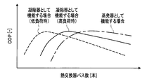
年間を通じた省エネルギ化の実現を目指し、熱交換器3を効率よく使用するために、熱交換器3の冷媒パス数は一般に、図2に示すグラフを考慮して、熱交換器3が高負荷時の凝縮器として機能する場合(図2の実線)、および蒸発器として機能する場合(図2の一点鎖線)のエネルギ消費効率COPを最大化する冷媒パス数を考慮することが望まれる。そして、低負荷時の凝縮器として機能する場合(図2の破線)のエネルギ消費効率COPを最大化する冷媒パス数を考慮することが望まれる。
なお、圧縮機1は熱交換器3での圧力損失が大きい場合には、所定の吐出量を維持できなくなる。ゆえに、熱交換器3が蒸発器として機能する場合に、冷媒パス数を多くして冷媒流速を下げることによって、圧縮機1の吐出能力を維持することができる。
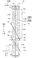
熱交換器3Aは、例えば、クロスフィンチューブ型の熱交換器3であり、アルミニウム製のフィン10を厚み方向に複数枚並べてなるフィンプレート11A,11Bと、冷媒配管20とを含んで構成されている。
なお、符号20は後記するあらゆる伝熱管を総称するものである。また、図3では紙面手前側(図3の左側)に見える冷媒配管20を太いパイプ形状で描き、紙面奥側(図3の右側)に位置する見えない冷媒配管20を破線で描いてある。
また、本実施形態における冷媒パス数とは、独立した冷媒パスの本数を意味している。つまり、本実施形態において冷媒パス数とは、冷媒流路20のうち、一方の端が他方の端とは少なくとも異なる列のフィンプレート11A,11B,・・・に連通している流路の本数に一致している。具体的に、冷媒パス数と言った場合は、伝熱管20a~23a、分岐合流部24a~24c、またはつなぎ配管35a,35bのいずれかを含む流路を介して各列のフィンプレート11A,11B,・・・を連通する流路の本数に一致している。つまり、本実施形態において冷媒パス数を数える場合は、説明の便宜上、伝熱管20a~23a、分岐合流部24a~24c、またはつなぎ配管35a,35bの本数を数えればよい。
また、同様にして逆に、例えばゲート41側から蒸発器として機能する熱交換器3Aの伝熱管28aに流入した冷媒は、冷媒配管20の冷媒パスを通流する過程で、1パスから最終的にNパス(Nは自然数)に分岐され、ゲート40側から四方弁2(図1参照)へと流入していく。
図3の太実線で示されるように、熱交換器3Aは、フィンプレート11A,11Bの各列および上下方向に区分された上部第1熱交換部領域HE1aおよび上部第2熱交換部領域HE1b、ならびに、下部第1熱交換部領域HE2aおよび下部第2熱交換部領域HE2bの、4つの熱交換部領域を備えている。
換言すると、複数列のフィンプレート11A,11Bは少なくとも4つの熱交換部領域HE1a~HE2bを有している。
また、下部第1熱交換部領域HE2aは、フィンプレート11Aのうち、ヘッダ12に連通する最も下方に配置された伝熱管23aよりも下部領域、すなわちつなぎ配管35aが接続される伝熱管27aを含む、それ以下の下部の熱交換部領域である。
また、下部第2熱交換部領域HE2bは、フィンプレート11Bのうち、1回目の分岐合流部24a,24bのうち、最も下方に配置された分岐合流部24bよりも下部の熱交換部領域である。または、フィンプレート11Bのうち、2回目の分岐合流部24cを経た後の伝熱管28aを含む、それ以下の下部の熱交換部領域である。
つまり、熱交換器3Aは、冷媒が一の熱交換部領域HE1a~HE2bから他の熱交換部領域HE1a~HE2bに流入する際、分岐合流部24a~24cを通る流路と、分岐合流部24a~24cを通らない流路とを有していると言える。なお、分岐合流部24a~24cを通らない流路とは、具体的にはつなぎ配管35a,35bを通る流路のことである。
そして、ガス側の口(ゲート40)に最も近い熱交換部領域HE1aが有する冷媒パス(伝熱管20a~23a)の数が、液側の口(ゲート41)に最も近い熱交換部領域HE2bが有する冷媒パス(伝熱管28a)の数よりも多くなるように、熱交換部領域HE1a~HE2b同士が分岐合流部24によって接続されている。
また、ガス側の口(ゲート40)に最も近い熱交換部領域HE1aは、液側の口(ゲート41)に最も近い熱交換部領域HE2bよりも上方に備わっている。
また、熱交換器3Aの冷媒配管20を通流する冷媒は、上部熱交換部領域HE1の一の熱交換部領域HE1aから流入したあと、隣接する上部熱交換部領域HE1の他の熱交換部領域HE1bを通流し、さらにつなぎ配管35a,35bを介して下部熱交換部領域HE2の一の熱交換部領域HE2aに流入し、隣接する下部熱交換部領域HE2の他の熱交換部領域HE2bを通流して、外部に流出される。
なお、熱交換器3Aが蒸発器として機能する場合も、前記した凝縮器の場合と同様のことが言える。この場合には、熱交換部領域HE1a~HE2bの、一の熱交換部領域HE1aから他の熱交換部領域HE1bへ冷媒が流入する際、冷媒パスの本数が増加する分岐合流部24a~24cを備えていると言うことができる。
その結果、気相が支配的な領域では流速増による圧力損失の増大によって熱交換効率の低下を引き起こしやすくなる。また、液相が支配的な領域では流速減による熱伝達率低下によって、熱交換効率の低下を引き起こしやすくなる。
また、液相冷媒が支配的な領域ではパス数を入口側の4パスに対して出口側1パスに、すなわちパス数を4分の1に減らして流速を上げ、熱伝達率の向上を図ることができる。
さらには、熱交換器3が蒸発器として機能する場合には、蒸発器時の入口側(凝縮器時の流出側)1パスに対して蒸発器時の流出側(凝縮器時の入口側)のパス数を4パスというように、4倍にすることができる。これによって、気相冷媒が支配的な領域で圧力損失が大きくなることを防止することができる。
これによって、熱交換器3Aの列数が例え2列の場合であったとしても、分岐合流を2回行わせることができる。このようにして、熱交換器3Aの設置スペースの省スペース化を実現できる。
さらに換言すると、熱交換部領域HE1a~HE2bは、少なくとも上部熱交換部領域HE1および下部熱交換部領域HE2に区分され、上部熱交換部領域HE1の上下方向の長さは、下部熱交換部領域HE2の上下方向の長さよりも長くなっていると言える。
これによって、1回目の分岐合流部24a,24bに流入する気相が支配的な領域のパス数がより多くなるようにすることができる。つまり、伝熱管20a~23aの本数を容易に4つ以上設置することができる。このようにすると、熱交換器3Aが特に蒸発器として機能する場合に、圧力損失を減らすことができる。
図4に示すように、熱交換器3Aの分岐合流部24a~24cの三叉形状は、フィンプレート11Aに冷媒流入(点R,Sとする)後から分岐合流部24a~24c(合流点Pとする)に到達するまでの距離(流路長)l,mが等しい形状(l=m)にされている。
また、熱交換器3Aの分岐合流部24a~24cの三叉形状は、冷媒が合流点Pにおいて流路RP,SPといずれも直交する方向に合流して吐き出される形状を呈している。
また、熱交換器3Aの分岐合流部24a~24cの三叉形状のうち、フィンプレート11Bに冷媒流入する点Qの上下方向の高さ位置は、点R,Sを結ぶ線分の中間位置の高さと等しくされている。
本発明の第1実施形態にかかわる熱交換器3Aは、複数列のフィンプレート11A,11Bを備えている。ここで、冷媒パスを各列のフィンプレート11A,11Bを連通する冷媒流路(連通路)と定義する。このとき、熱交換器3Aは、凝縮器時に冷媒が流入し、蒸発器時に冷媒が流出する冷媒パス20a~23aを、上下方向に少なくとも4つ備えている。
そして、熱交換器3Aが例えば凝縮器として機能する場合に、少なくとも4つに区分された熱交換器3Aの熱交換部領域HE1a~HE2bの、一の熱交換部領域から他の熱交換部領域へ冷媒が流入する際、パス数が減少する分岐合流部24a~24cを備えている。
また、液相冷媒が支配的な領域ではパス数を減らして流速を上げ、熱伝達率の向上を図ることができる。
これによって、熱交換器3Aのフィンプレート11A,11B,・・・の所要列数を減らし、熱交換器3Aの設置スペースの省スペース化を実現できる。
これによって、1回目の分岐合流部24a,24bに流入する気相が支配的な領域のパス数、具体的には伝熱管20a~23aの本数を、容易に4つ以上設置することができる。このようにすると、熱交換器3Aが特に蒸発器として機能する場合に、圧力損失を減らし、熱交換効率を向上することができる。
つまり、気相冷媒が支配的な上部第1熱交換部領域HE1aは、液相冷媒が支配的な下部第2熱交換部領域HE2bよりも上方に備わるようにされている。
このようにすることによって、特に液相冷媒が重力の影響を受けて、上部第1熱交換部領域HE1aよりも下方に備えられた下部第2熱交換部領域HE2bに集まりやすくなっている。つまり、気相冷媒を上部第1熱交換部領域HE1aに、液相冷媒を下部第2熱交換部領域HE2bに集まりやすくできる。これによって、熱交換効率を向上することができる。
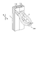
図5は、第2実施形態にかかわる熱交換器3Bの冷媒パスの様子を説明する模式図である。図6は、第2実施形態にかかわる熱交換器3Bの分岐合流部の拡大斜視図である。
以下、図5および図6を交互に参照しながら、第2実施形態にかかわる熱交換器3Bについて説明する。なお、図5は第1実施形態の図3に相当する図である。また、第1実施形態と同様の構成については、同一の符号を付して重複した説明を省略する。
これに対して、図5および図6(特に図6参照)に示すように、第2実施形態の熱交換器3Bでは、第1実施形態の熱交換器3Aと比較して、以下のような相違点を有している。具体的には、分岐合流部24aB~24cB(符号24Bで総称)の三叉形状のうち、フィンプレート11Bに冷媒流入する点Qの上下方向の高さ位置は、例えば点Rの上下方向の高さ位置よりも距離Tだけ高くなるようにされている。つまり、流路PQ間の伝熱管が、流路の途中から上方に捩じるように屈曲して形成されている。
これ以外の部分、例えばl=mとされている点や、合流点Pにおいて流路RP,SPといずれも直交する方向に合流した冷媒が吐き出される点については、第1実施形態と同様である。
なお、点Qの孔の位置が上方にずらして形成されている例で説明したが、これには特に限定されず、下方にずらして形成されていてもよい。また、距離T(図6参照)の大小も特に限定されない。
そして、ガス側の口(ゲート40)に最も近い熱交換部領域HE1aが有する冷媒パス(伝熱管20a~23a)の数が、液側の口(ゲート41)に最も近い熱交換部領域HE2bが有する冷媒パス(伝熱管28a)の数よりも多くなるように、熱交換部領域HE1a~HE2b同士が分岐合流部24B(24aB~24cB)によって接続されている。
また、ガス側の口(ゲート40)に最も近い熱交換部領域HE1aは、液側の口(ゲート41)に最も近い熱交換部領域HE2bよりも上方に備わっている。
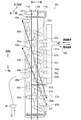
図7は、第3実施形態にかかわる熱交換器3Cの冷媒パスの様子を説明する模式図である。なお、図7は第1実施形態の図3に相当する図である。また、第1実施形態と同様の構成については、同一の符号を付して重複した説明を省略する。
なお、フィンプレートを3列化することに伴って、例えばフィンプレート11A,11Bの境界部分に、冷媒パスとなる伝熱管37a~37f(およびそれに付随するリターンベンド)が設置されている(図7と図3とを比較対照のこと)。これ以外の部分については、第1実施形態と同様である。
また、下部熱交換部領域HE2は、下部第1熱交換部領域HE2a、下部第2熱交換部領域HE2b、下部第3熱交換部領域HE2cを含んでなる領域となる。ここで、下部第1熱交換部領域HE2aおよび下部第2熱交換部領域HE2bは、フィンプレート11A,11Bのうち伝熱管37dよりも下部の部分である。また、下部第3熱交換部領域HE2cは、フィンプレート11Cのうち分岐合流部24bよりも下部の部分である。
また、本実施形態において冷媒パス数を数える場合は、第1実施形態と同様にして、伝熱管20a~23a、分岐合流部24a~24c、またはつなぎ配管35a,35b、伝熱管37a~37fの本数を数えればよい。
そして、ガス側の口(ゲート40)に最も近い熱交換部領域HE1aが有する冷媒パス(伝熱管20a~23a)の数が、液側の口(ゲート41)に最も近い熱交換部領域HE2cが有する冷媒パス(伝熱管28a)の数よりも多くなるように、熱交換部領域HE1a~HE2c同士が分岐合流部24によって接続されている。
また、ガス側の口(ゲート40)に最も近い熱交換部領域HE1aは、液側の口(ゲート41)に最も近い熱交換部領域HE2cよりも上方に備わっている。
また、各実施形態の構成の一部について、他の構成の追加・削除・置換をすることが可能である。
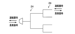
図8は、第1実施形態ないし第3実施形態にかかわる熱交換器の冷媒流路を模式的に説明する図である。なお、図8および後記する図9では、分岐合流部24以外で流路が屈曲している箇所はすべて直線で表わしている。
図9に示されるように、例えば分岐合流部24は、N叉形状を呈するもの、すなわちN分岐合流部24Nであってもよい。
しかし、上部熱交換部領域HE1の分岐合流部24a,24b、または下部熱交換部領域HE2の分岐合流部24cのみをフィンプレート11A,11Bの境界部分に移設する構成であってもよい。
つまり、分岐合流部24a~24cが異なるフィンプレート11A,11B,・・・間に、つなぎ配管35a,35bを介してたすき掛けで配置されていてもよい。
2 四方弁
3,7,3A,3B,3C 熱交換器
4,8 送風機
5,6 膨張弁
10 フィン
11A~11C フィンプレート
12 ヘッダ
20 冷媒配管
20a,21a,22a,23a,25a~25c,26a~26b,27a~27b,28a,37a~37f 伝熱管
24,24B,24N,24a~24c,24aB~24cB 分岐合流部
31a~31d,32a~32d,33a~33d リターンベンド
35a,35b つなぎ配管
40,41 ゲート
100 空気調和機
100A 室外機(室外ユニット)
100B 室内機(室内ユニット)
HE1 上部熱交換部領域
HE1a 上部第1熱交換部領域
HE1b 上部第2熱交換部領域
HE1c 上部第3熱交換部領域
HE2 下部熱交換部領域
HE2a 下部第1熱交換部領域
HE2b 下部第2熱交換部領域
HE2c 下部第3熱交換部領域
P,Q,R,S 点
T 距離
l,m 流路長
Claims (7)
- 空気調和機の室外ユニット、または、室内ユニットに用いられるフィンプレート式の熱交換器であって、
ガス状の冷媒が通流する配管と接続されるガス側の口と、
液状の冷媒が通流する配管と接続される液側の口と、
前記ガス側の口と前記液側の口とを結ぶ冷媒パスと、
空気と前記冷媒パスを通流する冷媒とを熱交換させる少なくとも4つの熱交換部領域と、
前記冷媒パスを分岐合流させ、前記熱交換部領域を、前記冷媒パスを介して前記ガス側の口と前記液側の口との間に直列で接続する分岐合流部と、を備え、
前記ガス側の口に近い前記熱交換部領域が有する前記冷媒パスの数が、前記液側の口に近い前記熱交換部領域が有する前記冷媒パスの数よりも多くなるように、前記熱交換部領域同士が前記分岐合流部によって接続されていること
を特徴とする、熱交換器。 - 前記ガス側の口に最も近い前記熱交換部領域は、前記液側の口に最も近い前記熱交換部領域よりも上方に備わること
を特徴とする、請求項1に記載の熱交換器。 - 前記熱交換器は、前記冷媒が一の熱交換部領域から他の熱交換部領域に流入する際、前記分岐合流部を通る流路と、前記分岐合流部を通らない流路とを有すること
を特徴とする、請求項1に記載の熱交換器。 - 前記熱交換部領域は、少なくとも上部熱交換部領域および下部熱交換部領域に区分され、
前記上部熱交換部領域の上下方向の長さは、前記下部熱交換部領域の上下方向の長さよりも長いこと
を特徴とする、請求項1に記載の熱交換器。 - 前記冷媒は、前記上部熱交換部領域の一の熱交換部領域から流入したあと、隣接する前記上部熱交換部領域の他の熱交換部領域を通流し、さらにつなぎ配管を介して前記下部熱交換部領域の前記一の熱交換部領域に流入し、隣接する前記下部熱交換部領域の前記他の熱交換部領域を通流して、外部に流出される
ことを特徴とする、請求項4に記載の熱交換器。 - 前記フィンプレートは2列または3列であり、
前記分岐合流部は三叉形状を呈するものを含むこと
を特徴とする、請求項1に記載の熱交換器。 - 空気調和機の室外ユニット、または、室内ユニットに用いられる熱交換器であって、
前記熱交換器は、
複数列のフィンプレートと、
各列の前記フィンプレートを連通する冷媒流路を冷媒パスと定義するとき、上下方向に少なくとも4つ設けられた、凝縮器時に冷媒が流入し、蒸発器時に前記冷媒が流出する冷媒パスと、を有し、
複数列の前記フィンプレートは少なくとも4つの熱交換部領域を有し、
前記熱交換器が凝縮器として機能する場合に、前記熱交換部領域の、一の熱交換部領域から他の熱交換部領域へ前記冷媒が流入する際、前記冷媒パスの本数が減少する分岐合流部を備える
ことを特徴とする、熱交換器。
Priority Applications (5)
| Application Number | Priority Date | Filing Date | Title |
|---|---|---|---|
| JP2017538801A JP6671380B2 (ja) | 2015-09-10 | 2015-09-10 | 熱交換器 |
| US15/758,416 US10907902B2 (en) | 2015-09-10 | 2015-09-10 | Heat exchanger |
| EP15903602.9A EP3348935B1 (en) | 2015-09-10 | 2015-09-10 | Heat exchanger |
| PCT/JP2015/075752 WO2017042940A1 (ja) | 2015-09-10 | 2015-09-10 | 熱交換器 |
| CN201580083019.XA CN108027181B (zh) | 2015-09-10 | 2015-09-10 | 热交换器 |
Applications Claiming Priority (1)
| Application Number | Priority Date | Filing Date | Title |
|---|---|---|---|
| PCT/JP2015/075752 WO2017042940A1 (ja) | 2015-09-10 | 2015-09-10 | 熱交換器 |
Publications (1)
| Publication Number | Publication Date |
|---|---|
| WO2017042940A1 true WO2017042940A1 (ja) | 2017-03-16 |
Family
ID=58239341
Family Applications (1)
| Application Number | Title | Priority Date | Filing Date |
|---|---|---|---|
| PCT/JP2015/075752 WO2017042940A1 (ja) | 2015-09-10 | 2015-09-10 | 熱交換器 |
Country Status (5)
| Country | Link |
|---|---|
| US (1) | US10907902B2 (ja) |
| EP (1) | EP3348935B1 (ja) |
| JP (1) | JP6671380B2 (ja) |
| CN (1) | CN108027181B (ja) |
| WO (1) | WO2017042940A1 (ja) |
Cited By (1)
| Publication number | Priority date | Publication date | Assignee | Title |
|---|---|---|---|---|
| JPWO2019142296A1 (ja) * | 2018-01-18 | 2020-12-17 | 三菱電機株式会社 | 熱交換器、室外ユニットおよび冷凍サイクル装置 |
Families Citing this family (1)
| Publication number | Priority date | Publication date | Assignee | Title |
|---|---|---|---|---|
| KR20200116848A (ko) * | 2019-04-02 | 2020-10-13 | 엘지전자 주식회사 | 실외열교환기 및 이를 포함하는 공기조화기 |
Citations (6)
| Publication number | Priority date | Publication date | Assignee | Title |
|---|---|---|---|---|
| US5076353A (en) * | 1989-06-06 | 1991-12-31 | Thermal-Werke Warme, Kalte-, Klimatechnik GmbH | Liquefier for the coolant in a vehicle air-conditioning system |
| JP2001066017A (ja) * | 1999-08-27 | 2001-03-16 | Hitachi Ltd | 空気調和機 |
| US6382310B1 (en) * | 2000-08-15 | 2002-05-07 | American Standard International Inc. | Stepped heat exchanger coils |
| JP2012237543A (ja) * | 2011-04-25 | 2012-12-06 | Panasonic Corp | 冷凍サイクル装置 |
| WO2013084508A1 (ja) * | 2011-12-07 | 2013-06-13 | パナソニック株式会社 | フィンチューブ型熱交換器 |
| JP2015140990A (ja) * | 2014-01-29 | 2015-08-03 | 日立アプライアンス株式会社 | 空気調和機 |
Family Cites Families (5)
| Publication number | Priority date | Publication date | Assignee | Title |
|---|---|---|---|---|
| JP2000304380A (ja) | 1999-04-22 | 2000-11-02 | Aisin Seiki Co Ltd | 熱交換器 |
| JP4922669B2 (ja) | 2006-06-09 | 2012-04-25 | 日立アプライアンス株式会社 | 空気調和機及び空気調和機の熱交換器 |
| US8387411B2 (en) * | 2007-11-30 | 2013-03-05 | Daikin Industries, Ltd. | Refrigeration apparatus |
| JP5423792B2 (ja) * | 2009-06-19 | 2014-02-19 | ダイキン工業株式会社 | 天井設置型空気調和装置 |
| WO2011048724A1 (ja) * | 2009-10-22 | 2011-04-28 | ダイキン工業株式会社 | 流路切換弁、及びそれを備えた空気調和機 |
-
2015
- 2015-09-10 WO PCT/JP2015/075752 patent/WO2017042940A1/ja active Application Filing
- 2015-09-10 US US15/758,416 patent/US10907902B2/en active Active
- 2015-09-10 CN CN201580083019.XA patent/CN108027181B/zh active Active
- 2015-09-10 EP EP15903602.9A patent/EP3348935B1/en active Active
- 2015-09-10 JP JP2017538801A patent/JP6671380B2/ja active Active
Patent Citations (6)
| Publication number | Priority date | Publication date | Assignee | Title |
|---|---|---|---|---|
| US5076353A (en) * | 1989-06-06 | 1991-12-31 | Thermal-Werke Warme, Kalte-, Klimatechnik GmbH | Liquefier for the coolant in a vehicle air-conditioning system |
| JP2001066017A (ja) * | 1999-08-27 | 2001-03-16 | Hitachi Ltd | 空気調和機 |
| US6382310B1 (en) * | 2000-08-15 | 2002-05-07 | American Standard International Inc. | Stepped heat exchanger coils |
| JP2012237543A (ja) * | 2011-04-25 | 2012-12-06 | Panasonic Corp | 冷凍サイクル装置 |
| WO2013084508A1 (ja) * | 2011-12-07 | 2013-06-13 | パナソニック株式会社 | フィンチューブ型熱交換器 |
| JP2015140990A (ja) * | 2014-01-29 | 2015-08-03 | 日立アプライアンス株式会社 | 空気調和機 |
Cited By (1)
| Publication number | Priority date | Publication date | Assignee | Title |
|---|---|---|---|---|
| JPWO2019142296A1 (ja) * | 2018-01-18 | 2020-12-17 | 三菱電機株式会社 | 熱交換器、室外ユニットおよび冷凍サイクル装置 |
Also Published As
| Publication number | Publication date |
|---|---|
| EP3348935A4 (en) | 2019-06-12 |
| US20180259265A1 (en) | 2018-09-13 |
| EP3348935A1 (en) | 2018-07-18 |
| JP6671380B2 (ja) | 2020-03-25 |
| US10907902B2 (en) | 2021-02-02 |
| CN108027181B (zh) | 2020-09-04 |
| JPWO2017042940A1 (ja) | 2018-07-12 |
| EP3348935B1 (en) | 2021-01-27 |
| CN108027181A (zh) | 2018-05-11 |
Similar Documents
| Publication | Publication Date | Title |
|---|---|---|
| JP5927415B2 (ja) | 冷凍サイクル装置 | |
| CN112204312B (zh) | 空气调节装置的室外机及空气调节装置 | |
| JP6364539B2 (ja) | 熱交換装置およびこれを用いた空気調和機 | |
| JP6011009B2 (ja) | 熱交換器および空気調和機 | |
| JP6351494B2 (ja) | 空気調和機 | |
| JP4889011B2 (ja) | 冷暖房空調システム | |
| US10670311B2 (en) | Heat exchanger | |
| JP6878511B2 (ja) | 熱交換器、空気調和装置、室内機および室外機 | |
| EP3062037B1 (en) | Heat exchanger and refrigeration cycle device using said heat exchanger | |
| CN110595111B (zh) | 换热器和多制冷系统空调机组 | |
| JP4845987B2 (ja) | 冷暖房空調システム | |
| WO2017042940A1 (ja) | 熱交換器 | |
| JP6925393B2 (ja) | 空気調和装置の室外機及び空気調和装置 | |
| JP2015014397A (ja) | 熱交換器 | |
| CN113646597B (zh) | 冷冻循环装置 | |
| JP6596541B2 (ja) | 空気調和機 | |
| JP6537868B2 (ja) | 熱交換器 | |
| WO2022172359A1 (ja) | 室外熱交換器および空気調和機 | |
| JP6698196B2 (ja) | 空気調和機 | |
| JP7050538B2 (ja) | 熱交換器および空気調和機 | |
| WO2019142296A1 (ja) | 熱交換器、室外ユニットおよび冷凍サイクル装置 |
Legal Events
| Date | Code | Title | Description |
|---|---|---|---|
| 121 | Ep: the epo has been informed by wipo that ep was designated in this application |
Ref document number: 15903602 Country of ref document: EP Kind code of ref document: A1 |
|
| ENP | Entry into the national phase |
Ref document number: 2017538801 Country of ref document: JP Kind code of ref document: A |
|
| WWE | Wipo information: entry into national phase |
Ref document number: 15758416 Country of ref document: US |
|
| NENP | Non-entry into the national phase |
Ref country code: DE |
|
| WWE | Wipo information: entry into national phase |
Ref document number: 2015903602 Country of ref document: EP |