WO2017033720A1 - 燃料ポンプ - Google Patents
燃料ポンプ Download PDFInfo
- Publication number
- WO2017033720A1 WO2017033720A1 PCT/JP2016/073240 JP2016073240W WO2017033720A1 WO 2017033720 A1 WO2017033720 A1 WO 2017033720A1 JP 2016073240 W JP2016073240 W JP 2016073240W WO 2017033720 A1 WO2017033720 A1 WO 2017033720A1
- Authority
- WO
- WIPO (PCT)
- Prior art keywords
- guide path
- pump
- gear
- fuel
- inner gear
- Prior art date
Links
Images


Classifications
-
- F—MECHANICAL ENGINEERING; LIGHTING; HEATING; WEAPONS; BLASTING
- F02—COMBUSTION ENGINES; HOT-GAS OR COMBUSTION-PRODUCT ENGINE PLANTS
- F02M—SUPPLYING COMBUSTION ENGINES IN GENERAL WITH COMBUSTIBLE MIXTURES OR CONSTITUENTS THEREOF
- F02M37/00—Apparatus or systems for feeding liquid fuel from storage containers to carburettors or fuel-injection apparatus; Arrangements for purifying liquid fuel specially adapted for, or arranged on, internal-combustion engines
- F02M37/04—Feeding by means of driven pumps
- F02M37/08—Feeding by means of driven pumps electrically driven
-
- F—MECHANICAL ENGINEERING; LIGHTING; HEATING; WEAPONS; BLASTING
- F04—POSITIVE - DISPLACEMENT MACHINES FOR LIQUIDS; PUMPS FOR LIQUIDS OR ELASTIC FLUIDS
- F04C—ROTARY-PISTON, OR OSCILLATING-PISTON, POSITIVE-DISPLACEMENT MACHINES FOR LIQUIDS; ROTARY-PISTON, OR OSCILLATING-PISTON, POSITIVE-DISPLACEMENT PUMPS
- F04C11/00—Combinations of two or more machines or pumps, each being of rotary-piston or oscillating-piston type; Pumping installations
- F04C11/008—Enclosed motor pump units
-
- F—MECHANICAL ENGINEERING; LIGHTING; HEATING; WEAPONS; BLASTING
- F04—POSITIVE - DISPLACEMENT MACHINES FOR LIQUIDS; PUMPS FOR LIQUIDS OR ELASTIC FLUIDS
- F04C—ROTARY-PISTON, OR OSCILLATING-PISTON, POSITIVE-DISPLACEMENT MACHINES FOR LIQUIDS; ROTARY-PISTON, OR OSCILLATING-PISTON, POSITIVE-DISPLACEMENT PUMPS
- F04C13/00—Adaptations of machines or pumps for special use, e.g. for extremely high pressures
- F04C13/005—Removing contaminants, deposits or scale from the pump; Cleaning
-
- F—MECHANICAL ENGINEERING; LIGHTING; HEATING; WEAPONS; BLASTING
- F04—POSITIVE - DISPLACEMENT MACHINES FOR LIQUIDS; PUMPS FOR LIQUIDS OR ELASTIC FLUIDS
- F04C—ROTARY-PISTON, OR OSCILLATING-PISTON, POSITIVE-DISPLACEMENT MACHINES FOR LIQUIDS; ROTARY-PISTON, OR OSCILLATING-PISTON, POSITIVE-DISPLACEMENT PUMPS
- F04C15/00—Component parts, details or accessories of machines, pumps or pumping installations, not provided for in groups F04C2/00 - F04C14/00
- F04C15/06—Arrangements for admission or discharge of the working fluid, e.g. constructional features of the inlet or outlet
-
- F—MECHANICAL ENGINEERING; LIGHTING; HEATING; WEAPONS; BLASTING
- F04—POSITIVE - DISPLACEMENT MACHINES FOR LIQUIDS; PUMPS FOR LIQUIDS OR ELASTIC FLUIDS
- F04C—ROTARY-PISTON, OR OSCILLATING-PISTON, POSITIVE-DISPLACEMENT MACHINES FOR LIQUIDS; ROTARY-PISTON, OR OSCILLATING-PISTON, POSITIVE-DISPLACEMENT PUMPS
- F04C2/00—Rotary-piston machines or pumps
- F04C2/08—Rotary-piston machines or pumps of intermeshing-engagement type, i.e. with engagement of co-operating members similar to that of toothed gearing
- F04C2/10—Rotary-piston machines or pumps of intermeshing-engagement type, i.e. with engagement of co-operating members similar to that of toothed gearing of internal-axis type with the outer member having more teeth or tooth-equivalents, e.g. rollers, than the inner member
- F04C2/102—Rotary-piston machines or pumps of intermeshing-engagement type, i.e. with engagement of co-operating members similar to that of toothed gearing of internal-axis type with the outer member having more teeth or tooth-equivalents, e.g. rollers, than the inner member the two members rotating simultaneously around their respective axes
-
- F—MECHANICAL ENGINEERING; LIGHTING; HEATING; WEAPONS; BLASTING
- F04—POSITIVE - DISPLACEMENT MACHINES FOR LIQUIDS; PUMPS FOR LIQUIDS OR ELASTIC FLUIDS
- F04C—ROTARY-PISTON, OR OSCILLATING-PISTON, POSITIVE-DISPLACEMENT MACHINES FOR LIQUIDS; ROTARY-PISTON, OR OSCILLATING-PISTON, POSITIVE-DISPLACEMENT PUMPS
- F04C2210/00—Fluid
- F04C2210/10—Fluid working
- F04C2210/1044—Fuel
-
- F—MECHANICAL ENGINEERING; LIGHTING; HEATING; WEAPONS; BLASTING
- F04—POSITIVE - DISPLACEMENT MACHINES FOR LIQUIDS; PUMPS FOR LIQUIDS OR ELASTIC FLUIDS
- F04C—ROTARY-PISTON, OR OSCILLATING-PISTON, POSITIVE-DISPLACEMENT MACHINES FOR LIQUIDS; ROTARY-PISTON, OR OSCILLATING-PISTON, POSITIVE-DISPLACEMENT PUMPS
- F04C2230/00—Manufacture
- F04C2230/60—Assembly methods
- F04C2230/602—Gap; Clearance
-
- F—MECHANICAL ENGINEERING; LIGHTING; HEATING; WEAPONS; BLASTING
- F04—POSITIVE - DISPLACEMENT MACHINES FOR LIQUIDS; PUMPS FOR LIQUIDS OR ELASTIC FLUIDS
- F04C—ROTARY-PISTON, OR OSCILLATING-PISTON, POSITIVE-DISPLACEMENT MACHINES FOR LIQUIDS; ROTARY-PISTON, OR OSCILLATING-PISTON, POSITIVE-DISPLACEMENT PUMPS
- F04C2240/00—Components
- F04C2240/40—Electric motor
-
- F—MECHANICAL ENGINEERING; LIGHTING; HEATING; WEAPONS; BLASTING
- F05—INDEXING SCHEMES RELATING TO ENGINES OR PUMPS IN VARIOUS SUBCLASSES OF CLASSES F01-F04
- F05C—INDEXING SCHEME RELATING TO MATERIALS, MATERIAL PROPERTIES OR MATERIAL CHARACTERISTICS FOR MACHINES, ENGINES OR PUMPS OTHER THAN NON-POSITIVE-DISPLACEMENT MACHINES OR ENGINES
- F05C2253/00—Other material characteristics; Treatment of material
- F05C2253/20—Resin
Definitions
- the present disclosure relates to a fuel pump that sucks and discharges fuel.
- a pump is disclosed in Patent Document 1 as a technology applicable to a fuel pump that sucks and discharges fuel.
- the pump includes an outer gear having a plurality of inner teeth, an inner gear having a plurality of outer teeth, which are eccentrically engaged with the outer gear in an eccentric direction, and a pump housing that rotatably accommodates the outer gear and the inner gear.
- the outer gear and the inner gear rotate while expanding and contracting the volume of a plurality of pump chambers formed between the two gears, so that liquid is sequentially sucked into each pump chamber and then discharged.
- the pump housing sandwiches the outer gear and the inner gear from both sides in the axial direction, so that a pair of sliding surfaces on which both the gears slide, and a suction guide path that is recessed from the sliding surfaces and guides the liquid on the suction side. And a discharge guide path for guiding the liquid on the discharge side.
- the pump housing has a linear exhaust pressure path that communicates the suction guide path and the discharge guide path. This exhaust pressure path prevents a pressure exceeding the discharge capacity from being applied and overloading the electric motor.
- the fuel pump may inhale foreign matter mixed in the fuel.
- both gears can be close to each other, so that the density of foreign matter in the fuel tends to be particularly high.
- the foreign matter in the vicinity of both gears may slide on the sliding surface in a place where there is no escape path such as a guide path. Due to the sliding of such foreign matter, a sliding scratch along the circumscribed circle of the inner gear occurs on the sliding surface, and the sliding scratch gradually deepens as the fuel pump is used.
- the inventors have found that pump efficiency decreases due to fuel leakage to the guide path.
- the linear exhaust pressure groove of Patent Document 1 can escape foreign matter at a nearby location at a location that overlaps the circumcircle of the inner gear, but at a location that does not overlap the circumscribed circle, the foreign matter at the proximity location. Slides on the sliding surface, and sliding scratches are generated. On the other hand, if the width of the linear exhaust pressure groove is increased so as to cover all the circumscribed circles, the suction guide path and the discharge guide path are connected, and the pump efficiency is significantly reduced.
- the present disclosure has been made in view of the problems described above, and an object thereof is to provide a fuel pump that suppresses a decrease in pump efficiency with use.
- the fuel pump of the present disclosure includes an outer gear having a plurality of internal teeth, An inner gear having a plurality of external teeth and eccentrically meshing with the outer gear; A pump housing that rotatably accommodates the outer gear and the inner gear, The outer gear and the inner gear rotate while expanding and reducing the volume of a plurality of pump chambers formed between the two gears, so that fuel is sequentially sucked into each pump chamber and then discharged.
- the pump housing By sandwiching the outer gear and the inner gear from both sides in the axial direction, a pair of sliding surfaces on which both the gears slide, A suction guide path that is recessed from at least one of the pair of sliding surfaces and guides fuel on the suction side; A discharge guide path that is recessed from the sliding surface provided with the suction guide path and guides fuel on the discharge side; A communication groove that is recessed from the sliding surface provided with the suction guide path and the discharge guide path, is formed in an arc shape along the circumscribed circle of the inner gear, and communicates with the suction guide path and the discharge guide path via both groove ends; It is characterized by having.
- a pump housing that rotatably accommodates an outer gear and an inner gear is provided with a suction guide path and a discharge guide path, and has a communication groove that is recessed from a sliding surface on which both gears slide.
- the communication groove is formed in an arc shape along the circumscribed circle of the inner gear. Therefore, it is possible to efficiently release the foreign matter at the adjacent location to the communication groove. Since the communication groove communicates with the suction guide path and the discharge guide path via both groove end portions, the foreign matter escaped to the communication groove escapes to the suction guide path or the discharge guide path.
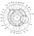
- FIG. 4 is a sectional view taken along line IV-IV in FIG. 1.
- FIG. 6 is a figure corresponding to FIG. 6 in an example among the modifications 1.
- FIG. 6 is a figure corresponding to FIG. 6 in another example among the modifications 1.
- FIG. 6 is a figure corresponding to FIG. 6 in another example among the modifications 1.
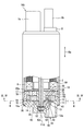
- the fuel pump 100 is a positive displacement trochoid pump as shown in FIG.
- the fuel pump 100 is a diesel pump that is mounted on a vehicle and used to pump light oil as fuel used for combustion of an internal combustion engine.
- the fuel pump 100 includes an electric motor 80 and a pump main body 10 housed in a cylindrical pump body 2, and a side cover 5 projecting outward from the opposite side of the pump main body 10 with the electric motor 80 sandwiched in the axial direction Da. Is the main constituent.
- the rotating shaft 80a of the electric motor 80 is rotationally driven by energization from an external circuit via the electrical connector 5a of the side cover 5.
- the outer gear 30 and the inner gear 20 of the pump body 10 rotate using the driving force of the rotating shaft 80a.
- the fuel sucked and pressurized in the gear housing chamber 56 in which both the gears 20 and 30 are housed is discharged from the discharge port 5 b of the side cover 5 through the fuel passage 6 outside the gear housing chamber 56.
- the fuel is stored in a fuel tank installed in the vehicle, and after passing through the suction filter, is sucked into the fuel pump 100 through the suction port 12a.
- the fuel in the fuel tank can be mixed with foreign matters such as sand, dust, and rust of the tank of the gas station.
- the electric motor 80 used in the fuel pump 100 is an inner rotor type brushless motor in which magnets are arranged in four poles and coils are formed in six slots.
- the electric motor 80 performs positioning control for rotating the rotary shaft 80a to the drive rotation side or the drive rotation reverse side. Thereafter, drive control is performed to rotate the rotary shaft 80a toward the drive rotation side from the position positioned by the positioning control.
- the drive rotation side indicates a side that is a positive direction (see FIG. 4) of a rotation direction Rig described later. Further, the reverse side of the drive rotation indicates the side that is the negative direction of the rotation direction Rig (see FIG. 4).
- the pump body 10 includes a pump housing 11, an inner gear 20, a joint member 60, and an outer gear 30.
- the pump housing 11 defines a cylindrical gear housing chamber 56 in which the gears 20 and 30 are rotatably housed by superimposing the pump cover 12 and the pump casing 16 in the axial direction Da.
- the pump housing 11 sandwiches both gears 20 and 30 from both sides in the axial direction Da, thereby forming a pair of sliding surfaces 70 and 75 on which the both gears 20 and 30 slide in a flat shape. .
- the pump cover 12 is formed in a disk shape having wear resistance by applying a surface treatment such as plating to a base material made of a metal having rigidity such as a steel material.
- the pump cover 12 projects outside from the end of the pump body 2 opposite to the side cover 5 with the electric motor 80 sandwiched in the axial direction Da.
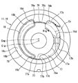
- the pump cover 12 is formed with a cylindrical suction port 12a and an arc groove-shaped suction passage 13 in order to suck fuel from the outside.
- the suction port 12a penetrates a specific opening portion Ss that is eccentric with respect to the inner center line Cig of the inner gear 20 in the pump cover 12 along the axial direction Da.
- the suction passage 13 extends from the sliding surface 70 of the pump cover 12 and opens toward the gear housing chamber 56 in the pump cover 12.
- the inner peripheral edge 13 a of the suction passage 13 extends along the rotational direction Rig of the inner gear 20 to a length of less than a half circumference.
- the outer peripheral edge 13b of the suction passage 13 extends to a length of less than a half circumference along the rotational direction Rog (see also FIG. 4) of the outer gear 30.
- the suction passage 13 is widened from the start end portion 13c toward the end portion 13d in the rotational directions Rig and Rog.
- the suction passage 13 communicates with the suction port 12a by opening the suction port 12a at the opening portion Ss of the groove bottom 13e.
- the width of the suction passage 13 is set to be smaller than the width of the suction port 12a in the entire opening portion Ss where the suction port 12a opens.
- the pump casing 16 shown in FIGS. 1, 3 and 4 is a component of the pump housing 11.
- the pump casing 16 is formed in a bottomed cylindrical shape having wear resistance by performing a surface treatment such as plating on a base material made of a metal having rigidity such as a steel material.
- the opening 16 a in the pump casing 16 is covered with the pump cover 12, thereby being closed over the entire circumference.
- the inner peripheral portion 16b of the pump casing 16 is formed in a cylindrical hole shape that is eccentric from the inner center line Cig.
- the pump casing 16 has an arc-hole-like discharge passage 17 for discharging fuel from the gear housing chamber 56.
- the discharge passage 17 extends from the sliding surface 75 of the pump casing 16 and penetrates the concave bottom portion 16c of the pump casing 16 along the axial direction Da.
- the inner peripheral edge portion 17 a of the discharge passage 17 extends along the rotational direction Rig of the inner gear 20 to a length of less than a half circumference.
- the outer peripheral edge portion 17 b of the discharge passage 17 extends to a length less than a half circumference along the rotation direction Rog of the outer gear 30.
- the discharge passage 17 is reduced in width toward the end portion 17d in the rotational directions Rig and Rog from the start end portion 17c.
- the pump casing 16 has a reinforcing rib 16d in the discharge passage 17.
- the reinforcing rib 16d is formed integrally with the pump casing 16, and is a rib that reinforces the pump casing 16 by straddling the discharge passage 17 in a direction intersecting the rotational direction Rig of the inner gear 20.
- the sliding surface 75 of the pump casing 16 has an eccentric side partition 75a and an opposite side partition 75b.
- the eccentric side partition portion 75a partitions the start end portion 18c of the suction groove 18 and the end portion 17d of the discharge passage 17 on the eccentric side of the inner gear 20 described in detail later.
- a communication groove 77 is provided in the eccentric side partition 75a.
- the opposite-side partition portion 75b partitions the end portion 18d of the suction groove 18 and the start end portion 17c of the discharge passage 17 on the opposite side of the eccentric side from the outer center line Cog that is the rotation center of the outer gear 30. Yes.
- a communication groove 78 is also provided in the opposite side partition 75b.
- a portion of the pump cover 12 that faces the discharge passage 17 across the pump chamber 40 is formed in an arc groove shape corresponding to the shape projected on the axial direction Da.
- the discharge groove 14 is formed.
- the discharge groove 14 is recessed from the sliding surface 70 and opens to the gear housing chamber 56 side of the pump cover 12.
- the suction passage 13 is provided with the discharge groove 14 and its outline approximately line-symmetrically across the joint housing chamber 58.
- the sliding surface 70 of the pump cover 12 has an eccentric side partition part 70a and an opposite side partition part 70b.
- the eccentric side partitioning portion 70 a partitions between the start end portion 13 c of the suction passage 13 and the end portion 14 d of the discharge groove 14 on the eccentric side of the inner gear 20.
- a communication groove 72 is provided in the eccentric side partition part 70a.
- the opposite side partitioning portion 70b partitions the end portion 13d of the suction passage 13 and the start end portion 14c of the discharge groove 14 on the opposite side of the eccentric side from the outer center line Cog.
- a communication groove 73 is also provided in the opposite partition portion 70b.
- the suction passage 13 of the pump cover 12 and the suction groove 18 of the pump casing 16 are provided as a suction guide path for guiding the fuel on the suction side. Further, a discharge groove 14 of the pump cover 12 and a discharge passage 17 of the pump casing 16 are provided as a discharge guide path for guiding the fuel on the discharge side.
- the joint housing chamber 58 of the pump cover 12 is recessed along the axial direction Da from the sliding surface 70 at a location facing the inner gear 20 on the inner center line Cig.
- the joint accommodating chamber 58 communicates with the gear accommodating chamber 56 on one side in the axial direction Da with respect to the outer gear 30 and the inner gear 20 to rotatably accommodate a main body portion 62 of the joint member 60 described later. Yes.
- a radial bearing is provided on the inner center line Cig of the concave bottom portion 16c of the pump casing 16 in order to radially support the rotating shaft 80a of the electric motor 80 that penetrates the concave bottom portion 16c. 50 is fitted and fixed.
- a thrust bearing 52 is fitted and fixed to the bottom of the joint housing chamber 58 on the inner center line Cig in the pump cover 12 in order to support the rotary shaft 80a in the axial direction Da.
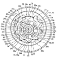
- the inner gear 20 and the outer gear 30 are so-called trochoidal gears having respective teeth having trochoidal curves.
- the inner gear 20 shown in FIGS. 1 and 4 is arranged eccentrically in the gear housing chamber 56 by sharing the inner center line Cig with the rotating shaft 80a. Further, the inner gear 20 has a thickness dimension slightly smaller than the corresponding dimension of the cylindrical gear housing chamber 56. Thus, the inner gear 20 has its inner peripheral portion 22 radially supported by the radial bearing 50 and both sides of the axial direction Da by the sliding surfaces 70 and 75.
- the inner gear 20 has an insertion hole 26 that is recessed along the axial direction Da at a location facing the joint housing chamber 58.
- a plurality of insertion holes 26 are provided at equal intervals in the circumferential direction, and each insertion hole 26 penetrates to the concave bottom portion 16c side.
- the joint member 60 shown in FIGS. 1, 4 and 5 is formed of a synthetic resin such as polyphenylene sulfide (PPS) resin, for example, and rotates both the gears 20 and 30 by relaying the rotating shaft 80a with the inner gear 20. It is a member to be made.
- the joint member 60 has a main body portion 62 and an insertion portion 64.
- the main body 62 is in a state of being fitted in the joint housing chamber 58 via the rotary shaft 80a and the fitting hole 62a.
- a plurality of insertion portions 64 are provided corresponding to each insertion hole 26.
- the insertion hole 26 and the insertion portion 64 of the present embodiment are numbers that avoid the number of poles and slots of the electric motor 80 in order to reduce the influence of torque ripple of the electric motor 80, and are particularly prime numbers. There are 5 each. Each insertion portion 64 extends along the axial direction Da from the outer peripheral side of the fitting hole 62a of the main body 62.
- each insertion hole 26 a corresponding insertion portion 64 is inserted with a gap.
- the insertion portion 64 is pressed against the inner wall of the insertion hole 26, whereby the driving force of the rotary shaft 80a is transmitted to the inner gear 20 via the joint member 60. That is, the inner gear 20 is rotatable in the rotation direction Rig around the inner center line Cig.
- FIG. 4 only a part of the insertion hole 26 and the insertion portion 64 are denoted by reference numerals.
- the inner gear 20 has a plurality of external teeth 24 a arranged at equal intervals in the rotation direction Rig on the outer peripheral portion 24.
- Each outer tooth 24 a is formed along an annular circumscribed circle Cc (also referred to as a tooth tip circle) with its tip protruding from the bottom of the tooth to the outer peripheral side, and according to the rotation of the inner gear 20, 17 and each groove
- the outer gear 30 is arranged coaxially in the gear housing chamber 56 by being eccentric with respect to the inner center line Cig of the inner gear 20.
- the inner gear 20 is eccentric with respect to the outer gear 30 in an eccentric direction De as a radial direction of the outer gear 30.
- the outer gear 30 has an outer diameter and a thickness that are slightly smaller than the corresponding dimensions of the cylindrical gear housing chamber 56.
- the outer gear 30 has its outer peripheral portion 34 supported by the inner peripheral portion 16b of the pump casing 16 and both sides of the axial direction Da by the sliding surfaces 70 and 75. Therefore, the outer gear 30 can rotate in a constant rotational direction Rog around the outer center line Cog that is eccentric from the inner center line Cig in conjunction with the inner gear 20.
- the outer gear 30 has a plurality of inner teeth 32 a arranged at equal intervals in the rotational direction Rog in the inner peripheral portion 32.
- the number of the inner teeth 32 a in the outer gear 30 is set to be one more than the number of the outer teeth 24 a in the inner gear 20.
- the number of inner teeth 32a is ten and the number of outer teeth 24a is nine.
- Each inner tooth 32a can be opposed to each passage 13, 17 and each groove 14, 18 in the axial direction Da according to the rotation of the outer gear 30, so that sticking to the sliding surfaces 70, 75 is suppressed. ing.
- the curvature at the tip of the inner tooth 32a is formed to be approximately the same as the curvature at the bottom of the outer tooth 24a, and the curvature at the bottom of the inner tooth 32a is equal to the curvature at the tip of the outer tooth 24a. They are formed to the same extent.
- the curvature of the outer teeth 24 a of the inner gear 20 at the tips of the teeth is larger than the curvature of the tips of the inner teeth 32 a of the outer gear 30.
- the inner gear 20 meshes with the outer gear 30 by relative eccentricity in the eccentric direction De.
- the gears 20 and 30 are engaged with each other with a small gap on the eccentric side, but a plurality of pump chambers 40 are formed between the gears 20 and 30 on the opposite side.
- the volume of the pump chamber 40 expands and contracts as the outer gear 30 and the inner gear 20 rotate.
- the volume of the pump chamber 40 is increased in the pump chamber 40 that is opposed to and communicates with the suction passage 13 and the suction groove 18 that form the suction guide path.
- fuel is sucked into the pump chamber 40 in the gear housing chamber 56 through the suction passage 13 from the suction port 12a.
- the suction passage 13 is widened from the start end portion 13c toward the end portion 13d (see also FIG. 2), the amount of fuel sucked through the suction passage 13 is the volume expansion amount of the pump chamber 40.
- the suction passage 13 is widened from the start end portion 13c toward the end portion 13d (see also FIG. 2)
- the volume of the pump chamber 40 is reduced in the pump chamber 40 that is opposed to and communicates with the discharge passage 17 and the discharge groove 14 that form the discharge guide passage.
- fuel is discharged from the pump chamber 40 to the outside of the gear housing chamber 56 through the discharge passage 17.
- the discharge passage 17 becomes wider toward the end portion 17d from the start end portion 17c (see also FIG. 3)
- the amount of fuel discharged through the discharge passage 17 is reduced by the volume of the pump chamber 40.
- the fuel that is sequentially sucked into the pump chamber 40 through the suction passage 13 and then discharged through the discharge passage 17 is discharged to the outside through the fuel passage 6 from the discharge port 5b.
- the fuel pressure on the discharge side becomes higher than the fuel pressure on the suction side by the above-described pump action.
- the communication grooves 72, 73, 77, and 78 that the pump housing 11 has will be described in more detail.
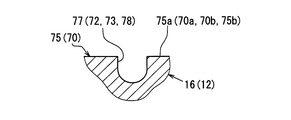
- the pump casing 16 has communication grooves 77 and 78 that are recessed from the sliding surface 75 in which the suction groove 18 and the discharge passage 17 are provided.
- the communication groove 77 provided in the eccentric side partition 75a communicates with the suction groove 18 via one groove end 77a and the start end 18c, and via the other groove end 77b and end 17d. It communicates with the discharge passage 17.
- the communication groove 77 is formed in an arc shape along the circumscribed circle Cc of the inner gear 20, so that the communication groove 77 communicates with the suction groove 18 through a portion of the start end portion 18c that intersects the outer peripheral edge portion 18b, and the end portion 17d. Among these, it communicates with the discharge passage 17 through a portion intersecting with the outer peripheral edge portion 17b.
- the width of the communication groove 77 is set to be sufficiently smaller than the width of the suction groove 18 and the width of the discharge passage 17. Further, the width and depth of the communication groove 77 are set substantially constant over the circumferential direction.
- the communication groove 77 is formed in a substantially triangular shape that is a bite tip shape.
- the communication groove 78 provided in the opposite partitioning portion 75b communicates with the suction groove 18 through one groove end portion 78a and a terminal end portion 18d, and the discharge passage through the other groove end portion 78b and the start end portion 17c. 17 communicates.
- the communication groove 78 is formed in an arc shape along the circumscribed circle Cc of the inner gear 20, so that the communication groove 78 communicates with the suction groove 18 through the intermediate portion of the end portion 18d, and passes through the intermediate portion of the start end portion 17c.
- the discharge passage 17 communicates with the discharge passage 17.
- the width of the communication groove 78 is set to be sufficiently smaller than the width of the suction groove 18 and the width of the discharge passage 17.
- the width and depth of the communication groove 78 are set to be substantially constant in the circumferential direction, and the shape of the longitudinal section is the same.
- the pump casing 16 is recessed from the sliding surface 75 over the entire circumference by the suction groove 18, the discharge passage 17, and the communication grooves 77, 78 at a location facing the circumscribed circle Cc of the inner gear 20 in the axial direction Da. It has a shape.
- the pump cover 12 has communication grooves 72 and 73 that are recessed from the sliding surface 70 in which the suction passage 13 and the discharge groove 14 are provided.
- the communication groove 72 provided in the eccentric side partition part 70a communicates with the suction passage 13 through one groove end part 72a and the start end part 13c, and via the other groove end part 72b and the end part 14d. It communicates with the discharge groove 14.
- the communication groove 72 is formed in an arc shape along the circumscribed circle Cc of the inner gear 20, so that the communication groove 72 communicates with the suction passage 13 through a portion intersecting the outer peripheral edge portion 13b in the start end portion 13c, and the end portion 14d.
- the width of the communication groove 72 is set to be sufficiently smaller than the width of the suction passage 13 and the width of the discharge groove 14.
- the width and depth of the communication groove 72 are set to be substantially constant over the circumferential direction, and the shape of the longitudinal section is also the same.
- the communication groove 73 provided in the opposite partition part 70b communicates with the suction passage 13 through one groove end part 73a and a terminal end part 13d, and discharge grooves through the other groove end part 73b and the start end part 14c. 14 communicates.
- the communication groove 73 is formed in an arc shape along the circumscribed circle Cc of the inner gear 20, so that the communication groove 73 communicates with the suction passage 13 through the intermediate portion of the terminal end portion 13d and passes through the intermediate portion of the start end portion 14c. And communicated with the discharge groove 14.
- the width of the communication groove 73 is set to be sufficiently smaller than the width of the suction passage 13 and the width of the discharge groove 14.
- the width and depth of the communication groove 73 are set to be substantially constant over the circumferential direction, and the shape of the longitudinal section is also the same.
- the pump casing 16 is recessed from the sliding surface 70 over the entire circumference by the suction passage 13, the discharge groove 14, and the communication grooves 72, 73 at a portion facing the circumscribed circle Cc of the inner gear 20 in the axial direction Da. It has a shape.
- the pump housing 11 that rotatably accommodates the outer gear 30 and the inner gear 20 is provided with the suction passage 13 and the suction groove 18 as the suction guide passage, and the discharge passage 17 and the discharge groove 14 as the discharge guide passage.
- communication grooves 72, 73, 77, 78 that are recessed from sliding surfaces 70, 75 on which both gears 20, 30 slide are provided.
- the communication grooves 72, 73, 77, and 78 Since the inner gear 20 is formed in an arc shape along the circumscribed circle Cc, it is possible to efficiently allow the foreign matter at the adjacent portion to escape to the communication grooves 72, 73, 77, 78.
- the communication grooves 72, 73, 77, and 78 communicate with the suction guide path and the discharge guide path through the respective groove end portions 72a to 72b, 73a to 73b, 77a to 77b, and 78a to 78b.
- the communication grooves 72, 73, 77, 78 are provided in at least the eccentric side partition portions 70a, 75a among the eccentric side partition portions 70a, 75a and the opposite side partition portions 70b, 75b. .
- both gears 20 and 30 are engaged with each other in a state of being closer to each other than on the opposite side. Therefore, the density of the foreign matter mixed in the fuel becomes higher at the adjacent portion on the eccentric side. easy.
- the communication grooves 72 and 77 provided in the eccentric side partition portions 70a and 75a allow foreign substances to escape, sliding scratches in the eccentric side partition portions 70a and 75a are hardly generated, and gradually. It is possible to suppress fuel leakage from the discharge guide path to the suction guide path due to the deepening of the sliding scratch. Therefore, it is possible to suppress a decrease in pump efficiency associated with the use of the fuel pump 100.
- the communication grooves 72, 73, 77, 78 are provided in both the eccentric side partition portions 70a, 75a and the opposite side partition portions 70b, 75b. By doing so, sliding scratches are less likely to occur in both of the partition portions 70a to 70b and 75a to 75b. Therefore, fuel leakage from the discharge guide path to the suction guide path due to gradually increasing sliding scratches. Can be reliably suppressed. Therefore, it is possible to suppress a decrease in pump efficiency associated with the use of the fuel pump 100.
- the joint housing chamber 58 that is recessed from the sliding surface 70 on one side in the axial direction Da accommodates the joint member 60 with respect to both the gears 20 and 30. Therefore, the two gears 20 and 30 are pushed from one side in the axial direction Da to the opposite side of the joint accommodating chamber 58 by the fuel flowing into the joint accommodating chamber 58, and the opposite sliding surface 75 and the two gears 20 and 30 are pressed. The gap between and becomes smaller and the sealing performance is improved.
- the communication grooves 72, 73, 77 and 78 are provided at least on the sliding surface 75 on the side opposite to the joint housing chamber 58. Since the communication grooves 77 and 78 provided on the sliding surface 75 make it difficult for sliding scratches to occur on the sliding surface 75, the sealing performance between the sliding surface 75 and both the gears 20 and 30 should be maintained. Can do. Therefore, it is possible to suppress a decrease in pump efficiency associated with the use of the fuel pump 100.
- the communication grooves 72, 73, 77, 78 are provided on both sides of the axial direction Da with respect to both the gears 20, 30. According to this, since it becomes difficult for a crack to generate
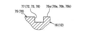
- the communication grooves 72, 73, 77, and 78 may be formed in a U shape in the longitudinal section.
- the communication grooves 72, 73, 77, 78 may be formed in a rectangular shape in the longitudinal section.
- the communication grooves 72, 73, 77, 78 may be formed in a V shape in the longitudinal section.
- the communication groove may be provided only on one side in the axial direction Da with respect to the outer gear 30 and the inner gear 20.
- the communication groove may be provided only on the sliding surface 75 of the pump casing 16 that is on the opposite side of the joint housing chamber 58 from the pair of sliding surfaces 70 and 75.
- the communication groove may be provided only in the eccentric side partition portions 70a and 75a among the eccentric side partition portions 70a and 75a and the opposite side partition portions 70b and 75b.
- the fuel pump may not include the joint member 60, and the pump housing 11 may not include the joint housing chamber 58.
- a shaft in which the rotating shaft 80a and the inner gear 20 are directly connected can be cited.
- the suction passage 13 and the discharge passage 17 are recessed from the same sliding surface, and the communication groove communicates with the suction passage 13 and the discharge passage 17 through both groove end portions. May be. Further, the suction groove 18 and the discharge groove 14 may be recessed from the same sliding surface, and the communication groove may be communicated with the suction groove 18 and the discharge groove 14 via both groove end portions.
- the fuel pump may be a pump that sucks and discharges gasoline other than light oil or liquid fuel based on these as fuel.
Priority Applications (2)
| Application Number | Priority Date | Filing Date | Title |
|---|---|---|---|
| KR1020177023024A KR101925618B1 (ko) | 2015-08-26 | 2016-08-08 | 연료펌프 |
| US15/564,860 US10612547B2 (en) | 2015-08-26 | 2016-08-08 | Fuel pump |
Applications Claiming Priority (2)
| Application Number | Priority Date | Filing Date | Title |
|---|---|---|---|
| JP2015-167059 | 2015-08-26 | ||
| JP2015167059A JP6380299B2 (ja) | 2015-08-26 | 2015-08-26 | 燃料ポンプ |
Publications (1)
| Publication Number | Publication Date |
|---|---|
| WO2017033720A1 true WO2017033720A1 (ja) | 2017-03-02 |
Family
ID=58100006
Family Applications (1)
| Application Number | Title | Priority Date | Filing Date |
|---|---|---|---|
| PCT/JP2016/073240 WO2017033720A1 (ja) | 2015-08-26 | 2016-08-08 | 燃料ポンプ |
Country Status (4)
| Country | Link |
|---|---|
| US (1) | US10612547B2 (ko) |
| JP (1) | JP6380299B2 (ko) |
| KR (1) | KR101925618B1 (ko) |
| WO (1) | WO2017033720A1 (ko) |
Cited By (1)
| Publication number | Priority date | Publication date | Assignee | Title |
|---|---|---|---|---|
| EP3376030A1 (en) * | 2017-03-13 | 2018-09-19 | Delphi Technologies IP Limited | Fluid pump with rotating pumping element wear reduction |
Families Citing this family (2)
| Publication number | Priority date | Publication date | Assignee | Title |
|---|---|---|---|---|
| JP6380364B2 (ja) * | 2015-12-17 | 2018-08-29 | 株式会社デンソー | 燃料ポンプ及び燃料ポンプモジュール |
| US20230323874A1 (en) * | 2022-04-12 | 2023-10-12 | Delphi Technologies Ip Limited | Fluid pump with thrust bearing driver |
Citations (7)
| Publication number | Priority date | Publication date | Assignee | Title |
|---|---|---|---|---|
| JPH0925809A (ja) * | 1995-07-10 | 1997-01-28 | Jatco Corp | トロコイド型オイルポンプ |
| JPH0996280A (ja) * | 1995-10-02 | 1997-04-08 | Yanmar Diesel Engine Co Ltd | トロコイドポンプの吐出脈動低減構造 |
| JP2001280261A (ja) * | 2000-03-30 | 2001-10-10 | Denso Corp | 燃料ポンプ |
| JP2012036861A (ja) * | 2010-08-09 | 2012-02-23 | Toyota Motor Corp | 車両用内接歯車型オイルポンプ |
| JP2012251523A (ja) * | 2011-06-06 | 2012-12-20 | Yamada Seisakusho Co Ltd | オイルポンプ |
| JP2014196706A (ja) * | 2013-03-29 | 2014-10-16 | 株式会社ジェイテクト | ポンプ |
| JP2015500953A (ja) * | 2011-12-22 | 2015-01-08 | ローベルト ボッシュ ゲゼルシャフト ミット ベシュレンクテル ハフツング | 内接型ギヤポンプ |
Family Cites Families (11)
| Publication number | Priority date | Publication date | Assignee | Title |
|---|---|---|---|---|
| US2871831A (en) * | 1959-02-03 | Internal gear machines | ||
| US3695791A (en) * | 1970-09-18 | 1972-10-03 | Emerson Electric Co | Variable sealed hydraulic pump or motor |
| JPS62156177A (ja) | 1985-12-28 | 1987-07-11 | Ricoh Co Ltd | インクジエツト記録用水性インク |
| JPH0914152A (ja) * | 1995-06-30 | 1997-01-14 | Jatco Corp | 内接歯車式回転ポンプ |
| US6332522B1 (en) * | 2000-05-26 | 2001-12-25 | Dana Corporation | Hydraulic coupling for vehicle drivetrain |
| JP2008001251A (ja) | 2006-06-23 | 2008-01-10 | Hitachi Ltd | ポンプ装置及びこのポンプ装置が適用されるパワーステアリング装置 |
| JP2009138528A (ja) | 2007-12-03 | 2009-06-25 | Jtekt Corp | 内接型ギアポンプ |
| JP2010025029A (ja) | 2008-07-22 | 2010-02-04 | Jtekt Corp | 内接式ギアポンプ |
| JP2011122548A (ja) | 2009-12-14 | 2011-06-23 | Jtekt Corp | 内接歯車ポンプ |
| JP5909949B2 (ja) | 2011-09-14 | 2016-04-27 | 株式会社ジェイテクト | 内接ギアポンプ |
| JP6418094B2 (ja) * | 2015-07-16 | 2018-11-07 | 株式会社デンソー | 燃料ポンプ |
-
2015
- 2015-08-26 JP JP2015167059A patent/JP6380299B2/ja not_active Expired - Fee Related
-
2016
- 2016-08-08 US US15/564,860 patent/US10612547B2/en not_active Expired - Fee Related
- 2016-08-08 KR KR1020177023024A patent/KR101925618B1/ko active IP Right Grant
- 2016-08-08 WO PCT/JP2016/073240 patent/WO2017033720A1/ja active Application Filing
Patent Citations (7)
| Publication number | Priority date | Publication date | Assignee | Title |
|---|---|---|---|---|
| JPH0925809A (ja) * | 1995-07-10 | 1997-01-28 | Jatco Corp | トロコイド型オイルポンプ |
| JPH0996280A (ja) * | 1995-10-02 | 1997-04-08 | Yanmar Diesel Engine Co Ltd | トロコイドポンプの吐出脈動低減構造 |
| JP2001280261A (ja) * | 2000-03-30 | 2001-10-10 | Denso Corp | 燃料ポンプ |
| JP2012036861A (ja) * | 2010-08-09 | 2012-02-23 | Toyota Motor Corp | 車両用内接歯車型オイルポンプ |
| JP2012251523A (ja) * | 2011-06-06 | 2012-12-20 | Yamada Seisakusho Co Ltd | オイルポンプ |
| JP2015500953A (ja) * | 2011-12-22 | 2015-01-08 | ローベルト ボッシュ ゲゼルシャフト ミット ベシュレンクテル ハフツング | 内接型ギヤポンプ |
| JP2014196706A (ja) * | 2013-03-29 | 2014-10-16 | 株式会社ジェイテクト | ポンプ |
Cited By (1)
| Publication number | Priority date | Publication date | Assignee | Title |
|---|---|---|---|---|
| EP3376030A1 (en) * | 2017-03-13 | 2018-09-19 | Delphi Technologies IP Limited | Fluid pump with rotating pumping element wear reduction |
Also Published As
| Publication number | Publication date |
|---|---|
| US20180087504A1 (en) | 2018-03-29 |
| US10612547B2 (en) | 2020-04-07 |
| KR101925618B1 (ko) | 2018-12-05 |
| KR20170105591A (ko) | 2017-09-19 |
| JP6380299B2 (ja) | 2018-08-29 |
| JP2017044139A (ja) | 2017-03-02 |
Similar Documents
| Publication | Publication Date | Title |
|---|---|---|
| WO2017033720A1 (ja) | 燃料ポンプ | |
| WO2017104375A1 (ja) | 燃料ポンプ及び燃料ポンプモジュール | |
| KR101869836B1 (ko) | 연료 펌프 | |
| KR101978318B1 (ko) | 연료펌프 | |
| US10024318B2 (en) | Fuel pump | |
| JP6361561B2 (ja) | 流体ポンプ | |
| KR102042809B1 (ko) | 연료펌프 | |
| JP5911744B2 (ja) | 内接歯車ポンプ | |
| WO2017104420A1 (ja) | 燃料ポンプ | |
| JP6163830B2 (ja) | ポンプ | |
| WO2017104376A1 (ja) | 燃料ポンプユニット | |
| JP5824391B2 (ja) | 内接歯車ポンプ | |
| JP4920971B2 (ja) | タンデム型トロコイドポンプ | |
| WO2016103663A1 (ja) | 燃料ポンプ | |
| JP2016217163A (ja) | 燃料ポンプ |
Legal Events
| Date | Code | Title | Description |
|---|---|---|---|
| 121 | Ep: the epo has been informed by wipo that ep was designated in this application |
Ref document number: 16839067 Country of ref document: EP Kind code of ref document: A1 |
|
| ENP | Entry into the national phase |
Ref document number: 20177023024 Country of ref document: KR Kind code of ref document: A |
|
| WWE | Wipo information: entry into national phase |
Ref document number: 15564860 Country of ref document: US |
|
| NENP | Non-entry into the national phase |
Ref country code: DE |
|
| 122 | Ep: pct application non-entry in european phase |
Ref document number: 16839067 Country of ref document: EP Kind code of ref document: A1 |