WO2017033509A1 - 詰め替え用液状内容物収容用紙製内容器 - Google Patents
詰め替え用液状内容物収容用紙製内容器 Download PDFInfo
- Publication number
- WO2017033509A1 WO2017033509A1 PCT/JP2016/064703 JP2016064703W WO2017033509A1 WO 2017033509 A1 WO2017033509 A1 WO 2017033509A1 JP 2016064703 W JP2016064703 W JP 2016064703W WO 2017033509 A1 WO2017033509 A1 WO 2017033509A1
- Authority
- WO
- WIPO (PCT)
- Prior art keywords
- panel
- panels
- pair
- inner container
- paper
- Prior art date
Links
- 239000007788 liquid Substances 0.000 title claims abstract description 36
- 238000007789 sealing Methods 0.000 claims abstract description 16
- 229920005992 thermoplastic resin Polymers 0.000 claims description 11
- 239000000463 material Substances 0.000 claims description 10
- 238000007599 discharging Methods 0.000 claims 3
- 229910000831 Steel Inorganic materials 0.000 claims 2
- 239000010959 steel Substances 0.000 claims 2
- 238000000034 method Methods 0.000 description 4
- 239000004033 plastic Substances 0.000 description 2
- 229920003023 plastic Polymers 0.000 description 2
- -1 polyethylene Polymers 0.000 description 2
- 229920003002 synthetic resin Polymers 0.000 description 2
- 239000000057 synthetic resin Substances 0.000 description 2
- 241001270131 Agaricus moelleri Species 0.000 description 1
- 229920000298 Cellophane Polymers 0.000 description 1
- 239000004698 Polyethylene Substances 0.000 description 1
- 239000004743 Polypropylene Substances 0.000 description 1
- XAGFODPZIPBFFR-UHFFFAOYSA-N aluminium Chemical compound [Al] XAGFODPZIPBFFR-UHFFFAOYSA-N 0.000 description 1
- 229910052782 aluminium Inorganic materials 0.000 description 1
- QVGXLLKOCUKJST-UHFFFAOYSA-N atomic oxygen Chemical compound [O] QVGXLLKOCUKJST-UHFFFAOYSA-N 0.000 description 1
- 230000004888 barrier function Effects 0.000 description 1
- 230000007423 decrease Effects 0.000 description 1
- 239000011888 foil Substances 0.000 description 1
- 239000002440 industrial waste Substances 0.000 description 1
- 229910052760 oxygen Inorganic materials 0.000 description 1
- 239000001301 oxygen Substances 0.000 description 1
- 229920000728 polyester Polymers 0.000 description 1
- 229920000573 polyethylene Polymers 0.000 description 1
- 229920001155 polypropylene Polymers 0.000 description 1
Images


Classifications
-
- B—PERFORMING OPERATIONS; TRANSPORTING
- B05—SPRAYING OR ATOMISING IN GENERAL; APPLYING FLUENT MATERIALS TO SURFACES, IN GENERAL
- B05B—SPRAYING APPARATUS; ATOMISING APPARATUS; NOZZLES
- B05B11/00—Single-unit hand-held apparatus in which flow of contents is produced by the muscular force of the operator at the moment of use
- B05B11/0005—Components or details
- B05B11/0037—Containers
-
- B—PERFORMING OPERATIONS; TRANSPORTING
- B65—CONVEYING; PACKING; STORING; HANDLING THIN OR FILAMENTARY MATERIAL
- B65D—CONTAINERS FOR STORAGE OR TRANSPORT OF ARTICLES OR MATERIALS, e.g. BAGS, BARRELS, BOTTLES, BOXES, CANS, CARTONS, CRATES, DRUMS, JARS, TANKS, HOPPERS, FORWARDING CONTAINERS; ACCESSORIES, CLOSURES, OR FITTINGS THEREFOR; PACKAGING ELEMENTS; PACKAGES
- B65D5/00—Rigid or semi-rigid containers of polygonal cross-section, e.g. boxes, cartons or trays, formed by folding or erecting one or more blanks made of paper
- B65D5/40—Rigid or semi-rigid containers of polygonal cross-section, e.g. boxes, cartons or trays, formed by folding or erecting one or more blanks made of paper specially constructed to contain liquids
-
- B—PERFORMING OPERATIONS; TRANSPORTING
- B05—SPRAYING OR ATOMISING IN GENERAL; APPLYING FLUENT MATERIALS TO SURFACES, IN GENERAL
- B05B—SPRAYING APPARATUS; ATOMISING APPARATUS; NOZZLES
- B05B11/00—Single-unit hand-held apparatus in which flow of contents is produced by the muscular force of the operator at the moment of use
- B05B11/0005—Components or details
- B05B11/0037—Containers
- B05B11/0054—Cartridges, i.e. containers specially designed for easy attachment to or easy removal from the rest of the sprayer
-
- B—PERFORMING OPERATIONS; TRANSPORTING
- B32—LAYERED PRODUCTS
- B32B—LAYERED PRODUCTS, i.e. PRODUCTS BUILT-UP OF STRATA OF FLAT OR NON-FLAT, e.g. CELLULAR OR HONEYCOMB, FORM
- B32B1/00—Layered products having a non-planar shape
-
- B—PERFORMING OPERATIONS; TRANSPORTING
- B32—LAYERED PRODUCTS
- B32B—LAYERED PRODUCTS, i.e. PRODUCTS BUILT-UP OF STRATA OF FLAT OR NON-FLAT, e.g. CELLULAR OR HONEYCOMB, FORM
- B32B27/00—Layered products comprising a layer of synthetic resin
- B32B27/06—Layered products comprising a layer of synthetic resin as the main or only constituent of a layer, which is next to another layer of the same or of a different material
- B32B27/10—Layered products comprising a layer of synthetic resin as the main or only constituent of a layer, which is next to another layer of the same or of a different material of paper or cardboard
-
- B—PERFORMING OPERATIONS; TRANSPORTING
- B65—CONVEYING; PACKING; STORING; HANDLING THIN OR FILAMENTARY MATERIAL
- B65D—CONTAINERS FOR STORAGE OR TRANSPORT OF ARTICLES OR MATERIALS, e.g. BAGS, BARRELS, BOTTLES, BOXES, CANS, CARTONS, CRATES, DRUMS, JARS, TANKS, HOPPERS, FORWARDING CONTAINERS; ACCESSORIES, CLOSURES, OR FITTINGS THEREFOR; PACKAGING ELEMENTS; PACKAGES
- B65D5/00—Rigid or semi-rigid containers of polygonal cross-section, e.g. boxes, cartons or trays, formed by folding or erecting one or more blanks made of paper
- B65D5/02—Rigid or semi-rigid containers of polygonal cross-section, e.g. boxes, cartons or trays, formed by folding or erecting one or more blanks made of paper by folding or erecting a single blank to form a tubular body with or without subsequent folding operations, or the addition of separate elements, to close the ends of the body
- B65D5/06—Rigid or semi-rigid containers of polygonal cross-section, e.g. boxes, cartons or trays, formed by folding or erecting one or more blanks made of paper by folding or erecting a single blank to form a tubular body with or without subsequent folding operations, or the addition of separate elements, to close the ends of the body with end-closing or contents-supporting elements formed by folding inwardly a wall extending from, and continuously around, an end of the tubular body
- B65D5/067—Gable-top containers
-
- B—PERFORMING OPERATIONS; TRANSPORTING
- B65—CONVEYING; PACKING; STORING; HANDLING THIN OR FILAMENTARY MATERIAL
- B65D—CONTAINERS FOR STORAGE OR TRANSPORT OF ARTICLES OR MATERIALS, e.g. BAGS, BARRELS, BOTTLES, BOXES, CANS, CARTONS, CRATES, DRUMS, JARS, TANKS, HOPPERS, FORWARDING CONTAINERS; ACCESSORIES, CLOSURES, OR FITTINGS THEREFOR; PACKAGING ELEMENTS; PACKAGES
- B65D5/00—Rigid or semi-rigid containers of polygonal cross-section, e.g. boxes, cartons or trays, formed by folding or erecting one or more blanks made of paper
- B65D5/42—Details of containers or of foldable or erectable container blanks
- B65D5/56—Linings or internal coatings, e.g. pre-formed trays provided with a blow- or thermoformed layer
- B65D5/563—Laminated linings; Coatings
-
- B—PERFORMING OPERATIONS; TRANSPORTING
- B65—CONVEYING; PACKING; STORING; HANDLING THIN OR FILAMENTARY MATERIAL
- B65D—CONTAINERS FOR STORAGE OR TRANSPORT OF ARTICLES OR MATERIALS, e.g. BAGS, BARRELS, BOTTLES, BOXES, CANS, CARTONS, CRATES, DRUMS, JARS, TANKS, HOPPERS, FORWARDING CONTAINERS; ACCESSORIES, CLOSURES, OR FITTINGS THEREFOR; PACKAGING ELEMENTS; PACKAGES
- B65D5/00—Rigid or semi-rigid containers of polygonal cross-section, e.g. boxes, cartons or trays, formed by folding or erecting one or more blanks made of paper
- B65D5/42—Details of containers or of foldable or erectable container blanks
- B65D5/72—Contents-dispensing means
- B65D5/74—Spouts
-
- B—PERFORMING OPERATIONS; TRANSPORTING
- B65—CONVEYING; PACKING; STORING; HANDLING THIN OR FILAMENTARY MATERIAL
- B65D—CONTAINERS FOR STORAGE OR TRANSPORT OF ARTICLES OR MATERIALS, e.g. BAGS, BARRELS, BOTTLES, BOXES, CANS, CARTONS, CRATES, DRUMS, JARS, TANKS, HOPPERS, FORWARDING CONTAINERS; ACCESSORIES, CLOSURES, OR FITTINGS THEREFOR; PACKAGING ELEMENTS; PACKAGES
- B65D77/00—Packages formed by enclosing articles or materials in preformed containers, e.g. boxes, cartons, sacks or bags
- B65D77/04—Articles or materials enclosed in two or more containers disposed one within another
-
- B—PERFORMING OPERATIONS; TRANSPORTING
- B32—LAYERED PRODUCTS
- B32B—LAYERED PRODUCTS, i.e. PRODUCTS BUILT-UP OF STRATA OF FLAT OR NON-FLAT, e.g. CELLULAR OR HONEYCOMB, FORM
- B32B2439/00—Containers; Receptacles
- B32B2439/40—Closed containers
- B32B2439/62—Boxes, cartons, cases
Definitions
- the present invention relates to an inner container made of refillable liquid content storage paper that is used while being accommodated in a refill container.
- a refillable container that can be refilled with liquid contents.
- the inner container is taken out of the refill container and replaced with a new inner container.
- a container formed of a synthetic resin for example, see Patent Document 1
- a pouch for example, see Patent Document 2
- the lid As a refill container, the lid is equipped with a pump that sucks the liquid contents in the inner container accommodated in the container body and discharges it to the outside.
- the opening of the container body is closed with the lid body,
- the pump provided in the lid body is It is provided in the center of the lid for ease of work.
- the suction opening of the inner container is required to be formed at the center of the upper surface portion.
- Gable-top type paper containers and flat-top type paper containers are known as paper containers for storing liquids.
- the invention described in claim 1 is characterized in that the refillable liquid content container is provided with a suction port into which a suction pipe of a pump that sucks and discharges the liquid content is inserted.
- An inner container made of paper which is made of a paper material in which a thermoplastic resin is laminated on both sides, has four body panels, and is joined to the edge by a longitudinal seal panel to form a rectangular tube A pair of upper surface forming panels that are stacked on top and bottom of the upper surface of the body panel, and are formed on the upper surface of the body inner panel.
- a pair of side panels positioned between the panels and facing each other and folded in accordance with the overlapping of the pair of upper surface portion forming panels are continuously provided, and the pair of upper surface portion forming panels are positioned at the center thereof. Then sucking A hole formed as an opening is formed, and at least one of the pair of upper surface portion forming panels formed in the upper surface portion forming panel is sealed with a breakable film, and the pair of upper surface portions
- the upper panel forming panel and the side panel stacked on the upper side, the upper panel forming panel and the side panel stacked on the upper side are formed to be sealed.
- the invention according to claim 2 is an inner container made of refill paper provided with a suction port into which a suction pipe of a pump that sucks and discharges liquid contents to the outside is provided, and the inner container made of paper is , Made of paper material laminated with thermoplastic resin on both sides, provided with four body panels, and having a body part that is formed into a square cylinder by joining the edges by a longitudinal seal panel, The bottom part of the inner container has a pair of gabled roof-shaped bottom face forming panels facing each other at the lower end of the body panel and having a belt-like outer seal panel in the lower part, and a belt-like shape having a lower height than the outer seal panel.
- a pair of facing wall-shaped bottom surface forming panels that have inner sealing panels and that are opposed to each other are connected in series, and the facing wall-shaped bottom surface forming panel is folded between the gable roof-shaped bottom surface forming panels, With facing surfaces to each other is sealed, wherein said is facing surfaces of the opposed faces and the inner sealing panel with the outer seal panel and the inner sealing panel also sealed form.
- the invention according to claim 3 is an inner container made of refill paper having an upper surface provided with a suction port into which a suction pipe of a pump that sucks liquid content and discharges it to the outside.
- the upper surface portion of the inner container is positioned between the pair of upper surface portion forming panels and the pair of upper surface portion forming panels facing each other at the upper end of the body panel, and is opposed to each other.
- a pair of side panels that are folded along with the overlapping of the upper surface forming panels are provided in series, and the pair of upper surface forming panels are formed with a hole serving as the suction port located at the center thereof.
- Top part of the shape The hole formed in at least the lower upper surface forming panel of the panels is sealed with a breakable film, and the upper surface forming panel is stacked on the lower side of the pair of upper surface forming panels.
- the upper surface forming panel and the side panel overlaid on the upper side are formed to be sealed, and the bottom surface of the paper inner container is formed at the lower end of the body panel, and at the lower part, a belt-shaped outer seal.
- a pair of gabled roof-shaped bottom surface forming panels having panels and a pair of gable wall-shaped bottom surface forming panels facing each other having a belt-shaped inner seal panel having a lower height than the outer seal panel
- the gable wall-shaped bottom surface forming panel is folded between the gable roof-shaped bottom surface forming panels, and the opposing surfaces of the opposed outer seal panels are sealed, and the outer seal panel and the front Opposing faces of the opposing faces and the inner sealing panel the inner sealing panel also characterized in that it is formed by sealing.
- the periphery of the upper surface portion forming panel stacked on the lower side of the pair of upper surface portion forming panels and the upper surface portion forming panel and the side panel stacked on the upper side are formed to be sealed, so that the paper A suction port can be easily formed in the center of the upper surface portion of the inner container, and the liquid content can be sealed in the paper inner container.
- the suction port formed in the upper surface portion of the paper inner container is located at the center of the opening of the container main body in the refill container.
- the lid is closed regardless of the direction of the lid that closes the opening of the container main body by providing the center of the lid that closes the opening of the container main body. Since the suction pipe arranged on the lower side of the body is surely inserted into the paper inner container from the suction port formed in the upper surface portion of the paper inner container, the paper in which the liquid content is enclosed It is possible to easily replace the inner container.
- the face wall-shaped bottom surface forming panel is folded between the opposing surfaces of the outer seal panels facing each other, and the opposing surfaces of the outer seal panel and the inner seal panel and the inner seals are sealed. Because the opposing surfaces of the Panel are also formed are sealed, a bottom portion of the paper-made inner container facing downward pyramidal.
- the liquid content in the paper inner container is collected at the top of the downward quadrangular pyramid on the bottom surface portion when the amount is reduced, and the opening of the container body in the refill container is closed with the lid,
- the tip of the suction pipe is set so as to be positioned at the top of the downward quadrangular pyramid on the bottom surface of the paper inner container.
- the inner container made of paper is made of a paper material in which a thermoplastic resin is laminated on both sides, and includes four body panels, and the edge portion is formed by a vertical seal panel. Are joined to each other, and the upper surface portion of the paper inner container is opposed to each other on the upper end of the body panel, and a pair of upper surface portion forming panels are vertically stacked.
- the periphery of the upper surface portion forming panel stacked on the lower side of the pair of upper surface portion forming panels and the upper surface portion forming panel and the side panel stacked on the upper side are formed to be sealed, so that the paper A suction port can be easily formed in the center of the upper surface portion of the inner container, and the liquid content can be sealed in the paper inner container.
- the suction port formed in the upper surface portion of the paper inner container is located at the center of the opening of the container main body in the refill container.
- the lid is closed regardless of the direction of the lid that closes the opening of the container main body by providing the center of the lid that closes the opening of the container main body. Since the suction pipe arranged on the lower side of the body is surely inserted into the paper inner container from the suction port formed in the upper surface portion of the paper inner container, the paper in which the liquid content is enclosed It is possible to easily replace the inner container.
- the bottom portion of the inner container made of paper is lower than the pair of gable roof-shaped bottom surface forming panels that have a belt-like outer seal panel at the lower portion and opposed to each other at the lower end of the body panel, and the outer seal panel
- a pair of face-wall-shaped bottom face forming panels facing each other having a belt-shaped inner seal panel having a height are connected to each other, and the face wall-shaped bottom face forming panel is folded between the gable roof-shaped bottom face forming panels to face each other. Since the opposed surfaces of the outer seal panel are sealed, the opposed surfaces of the outer seal panel and the inner seal panel and the opposed surfaces of the inner seal panel are also sealed to form the paper.
- the bottom part of the inner container is a downward quadrangular pyramid.
- the liquid content in the paper inner container is collected at the top of the downward quadrangular pyramid on the bottom surface portion when the amount is reduced, and the opening of the container body in the refill container is closed with the lid,
- the tip of the suction pipe is set so as to be positioned at the top of the downward quadrangular pyramid on the bottom surface of the paper inner container.
- FIG. 2 is a cross-sectional view taken along the line AA in FIG.
- FIG. 3 is a cross-sectional view taken along the line BB in FIG.
- It is an expanded view which shows the carton blank before the assembly process of the inner container made from refill paper shown in FIG.
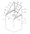
- It is explanatory drawing which shows the process of forming the upper surface part of the inner container made from refill paper shown in FIG.
- It is explanatory drawing which shows the process of forming the upper surface part of the inner container made from refill paper shown in FIG.
- It is explanatory drawing which shows the process of forming the upper surface part of the inner container made from refill paper shown in FIG.
- It is a disassembled perspective view which shows an example of the refill container which accommodates the inner container made from refill paper shown in FIG.
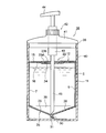
- It is longitudinal cross-sectional explanatory drawing which shows the state which accommodated the refill paper inner container shown in FIG. 1 in the refill container shown in FIG.
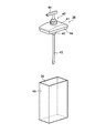
- FIG. 1 is a perspective view showing an example of an embodiment of an inner container made of refill paper according to the present invention
- FIG. 2 is a sectional view taken along line AA in FIG. 1
- FIG. 3 is a sectional view taken along line BB in FIG.
- FIG. 5 is an exploded view showing a carton blank before assembly processing of the refill paper inner container shown in FIG. 1
- FIG. 5 is an explanatory view showing a process of forming the upper surface portion of the refill paper inner container shown in FIG. 1
- FIG. 7 is an exploded perspective view showing an example of a refill container that houses the refill paper inner container shown in FIG. 1
- FIG. 8 is an exploded perspective view of FIG. It is longitudinal cross-sectional explanatory drawing which shows the state which accommodated the refill paper inner container shown in FIG. 1 in the refill container shown.
- the refillable paper inner container 1 of this example is made of a paper material in which a thermoplastic resin is laminated on both sides, and has four body panels 5, 6, 7, 8 via body body vertical folding lines 2, 3, 4. And has a body portion formed in a square cylindrical shape by joining the edge portion of the body panel 5 by a longitudinal seal panel 10 connected to the body panel 8 via a seal vertical folding line 9. .
- the upper surface portion 12 of the inner paper container 1 is configured as follows in this example.
- a pair of upper surface forming panels 15, 16 that are opposed to each other via the top horizontal folding lines 13, 14 are connected to the upper ends of the body panels 5, 7, and the lower side of the upper surface forming panel 15.
- a seal panel 17 that is sealed to the inner surface of the upper surface portion forming panel 15 is connected to the upper end of the upper surface portion forming panel 16 that overlaps with the upper surface portion forming panel 16.
- the upper end portions of the body panel 6 and 8 are positioned between the pair of upper surface forming panels 15 and 16 and opposed to each other, and are folded as the pair of upper surface forming panels 15 and 16 overlap.
- a pair of side panels 18 and 19 are connected to each other via top horizontal folding lines 20 and 21.
- the upper surface forming panels 15 and 16 are formed with holes 23a and 23b which are located at the centers of the upper surface forming panels 15 and 16 and serve as the suction ports 22, and the holes 23a and 23b are formed when the upper surface forming panels 15 and 16 are overlapped. It opens so that the center of the hole 23a and the hole 23b may correspond.
- a breakable film 24 is provided on the back surface of the upper surface forming panel 16 so as to close the hole 23b, and can be broken by piercing a suction pipe 45 of a pump 42 described later.
- the film 24 that closes the hole 23b is provided on the back surface of the upper surface forming panel 16.
- the present invention is not limited to this, and the film 24 may be provided on the surface of the upper surface forming panel 16. It may be provided on both the front and back surfaces of the part forming panel 16.
- a known film such as polyethylene, polypropylene, polyester, cellophane or the like can be used, but is not particularly limited.
- the film 24 is a thermoplastic resin
- the holes 23b formed in the upper surface forming panel 16 can be easily closed by heat sealing.
- the film 24 may be laminated with aluminum foil or paper for the purpose of improving breakability, light shielding properties, oxygen barrier properties and the like.
- the upper surface portion forming panel 16 is first folded inward. Then, the side panels 18 and 19 are folded in a triangular shape toward the inner surface side, and the upper opening of the trunk portion 11 is closed with the upper surface portion forming panel 16. Then, the seal panel 17 connected to the upper end of the upper surface portion forming panel 16 is sealed to the inner surface of the upper surface portion forming panel 15 in the range of S1, and the side surfaces of the upper surface portion forming panel 16 are folded in a triangular shape. The panels 18 and 19 are sealed within the range of S2 (see FIG. 5).
- the upper surface forming panel 15 is overlaid on the upper surface forming panel 16 (see FIG. 6) so that the side panels 18 and 19 are folded outward (in the direction of the arrow shown in FIG. 5).
- the side panels 18 and 19 projecting to the outside of the part 11 are folded downward (in the direction of the arrow shown in FIG. 6) and fixed to the body part 11 by adhesion or the like to form the upper surface part 12.
- bottom face part 25 of the paper inner container 1 in this example, it is comprised as follows.
- a pair of gable roof-shaped bottom surface forming panels 28 and 29 that are opposed to each other via bottom lateral folding lines 26 and 27 are connected to the lower ends of the body panels 5 and 7.
- Strip-shaped outer seal panels 30 and 31 are continuously provided below the gable roof-shaped bottom surface forming panels 28 and 29.
- a pair of end wall shaped bottom surface forming panels 34 and 35 facing each other through the bottom horizontal folding lines 32 and 33 are connected to the lower ends of the body panel 6 and 8.
- Belt-shaped inner seal panels 36 and 37 having a height lower than that of the outer seal panels 30 and 31 are connected to the lower portions of the end wall-shaped bottom surface forming panels 34 and 35.
- the gable wall-shaped bottom surface forming panel 28 and 29 is interposed between the gable roof-shaped bottom surface forming panels 28 and 29.
- 34 and 35 are folded, the opposing surfaces of the opposing outer seal panels 30 and 31 are sealed, and the opposing surfaces of the outer seal panels 30 and 31 and the inner seal panels 36 and 37 and the inner seal panels 36 and 37 are also sealed.
- the opposing surfaces of 37 are also sealed and formed into a so-called inverted gable top-shaped downward quadrangular pyramid (see FIGS. 2 and 3).
- the upper surface portion 12 has a pair of upper surface portion forming panels 15 and 16 that are opposed to each other and are stacked on the upper ends of the body panel 5, 6, 7, and 8 respectively.
- a pair of side panels 18 and 19 which are located between the upper surface forming panels 15 and 16 and face each other and which are folded in accordance with the overlapping of the upper surface forming panels 15 and 16 are continuously provided.
- 16 are formed with holes 23a, 23b which are located at the center and serve as the suction port 22, and the upper surface forming panel 15 and the side surface which are stacked on the upper and lower sides of the upper surface forming panel 16 which are stacked on the lower side. Since the panels 18 and 19 are sealed, the suction port 22 can be easily formed in the center of the upper surface portion 12 of the paper inner container 1.
- the bottom surface 25 has a pair of gable roof-shaped bottom surface forming panels 28 and 29 having outer seal panels 30 and 31 at the lower ends of the body panels 5, 6, 7 and 8 and facing each other, and outer seals
- a pair of end wall-shaped bottom surface forming panels 34 and 35 having inner seal panels 36 and 37 having a lower height than the panels 30 and 31 and facing each other are connected to each other, and the end surface is formed between the gable roof-shaped bottom surface forming panels 28 and 29.
- the wall-shaped bottom surface forming panels 34 and 35 are folded to seal the opposing surfaces of the outer seal panels 30 and 31, and the opposing surfaces of the outer seal panels 30 and 31 and the inner seal panels 36 and 37 and the inner seals. Since the opposing surfaces of the panels 36 and 37 are also formed to be sealed, the downward quadrangular pyramid bottom portion 25 can be easily formed.
- FIG. 7 shows an example of a refill container that accommodates the paper inner container 1 configured as described above.
- the refill container 38 of this example has a plastic container body 40 having an opening 39 in the upper part. And a plastic lid 41 that closes the opening 39 of the container body 40, and the liquid contents in the paper inner container 1 provided in the lid body 41 and accommodated in the container body 40 are sucked and discharged to the outside. And a pump 42.
- the pump 42 is provided with a cylindrical cylinder portion 43, a discharge nozzle 44 that is provided at an upper portion of the cylindrical cylinder portion 43 and also serves as an operation portion of a piston that is slidably fitted in the cylindrical cylinder portion 43, and the cylindrical cylinder
- the suction pipe 45 is provided at the lower part of the portion 43.
- the pump 42 is provided at the center of the lid body 41, the cylindrical cylinder portion 43 is fixed to the lid body 41 through the central portion, and the discharge nozzle 44 is disposed above the lid body 41.
- a suction pipe 45 is arranged on the lower side. When the opening 39 of the container body 40 is closed with the lid 41, the suction pipe 45 disposed on the lower side of the lid 41 from the suction port 22 formed on the upper surface portion 12 of the paper inner container 1. Is inserted into the paper inner container 1.
- the suction port 22 formed in the upper surface portion 12 of the paper inner container 1 is a container in the refill container 38. Since it is located in the center of the opening 39 of the main body 40, when the opening 39 of the container main body 40 is closed by the lid 41 regardless of the direction of the lid 41 that closes the opening 39 of the container main body 40, the lid 41 The suction pipe 45 arranged on the lower side securely inserts the liquid content from the suction port 22 formed in the upper surface portion 12 of the paper inner container 1 into the paper inner container 1. The replacement work of the inner paper container 1 can be easily performed.
- the bottom surface portion 25 of the paper inner container 1 has a downward quadrangular pyramid shape
- the liquid content in the paper inner container 1 is collected at the top of the downward quadrangular pyramid shape in the bottom surface portion 25 as the amount decreases.
Landscapes
- Engineering & Computer Science (AREA)
- Mechanical Engineering (AREA)
- Cartons (AREA)
- Packages (AREA)
Abstract
本発明は、上面部の中央に吸い出し口を容易に形成することができる詰め替え用液状内容物収容用紙製内容器を得るものである。4つの胴部パネル(5,6,7,8)で四角の筒状に形成した胴部(11)を有する紙製内容器(1)の上面部(12)を、胴部パネル(5,6,7,8)の上端に、互いに対向し上下に重ねられる一対の上面部形成パネル(15,16)と、上面部形成パネル(15,16)の間に位置して互いに対向し、上面部形成パネル(15,16)の重ね合わせに伴って折り畳まれる一対の側面パネル(18,19)を連設し、上面部形成パネル(15,16)に、その中央に位置して吸い出し口(22)となる穴(23a,23b)を形成し、下側の上面部形成パネル(16)に形成した穴(23b)を破断可能なフィルム(24)で封止し、上面部形成パネル(16)の周囲と、上側に重ねられた上面部形成パネル(15)及び側面パネル(18,19)とをシールして形成した。
Description
本発明は、詰め替え用容器に収容されて使用される詰め替え用液状内容物収容用紙製内容器に関する。
液状内容物の詰め替えが可能な詰め替え容器にあって、詰め替え用液状内容物を収容した容器を内容器として用意し、詰め替え容器内に内容器を収容した状態で内容器内の液状内容物を取り出し、内容器内の液状内容物を消尽したら、詰め替え容器から内容器を取り出し、新しい内容器に交換することにより詰め替えを行えるようにしたものがある。
このような詰め替え容器で使用される内容器として、合成樹脂で形成された容器(例えば、特許文献1参照。)や、パウチと称される袋状の容器(例えば、特許文献2参照。)が知られている。
このような詰め替え容器で使用される内容器として、合成樹脂で形成された容器(例えば、特許文献1参照。)や、パウチと称される袋状の容器(例えば、特許文献2参照。)が知られている。
しかしながら、特許文献1、2に記載されている詰め替え容器で使用される内容器は合成樹脂製であるため、取り替え後の使用済み内容器が産業廃棄物となり、廃棄が面倒であるといった問題がある。このような問題を解消するものとして、内容器を紙製にすることが考えられるが、この場合、次のような問題が生じることになる。
詰め替え容器として、蓋体に容器本体内に収容された内容器内の液状内容物を吸い込んで外部へ吐出するポンプを備え、容器本体の開口部を蓋体で閉じたとき、蓋体の下側に配置されているポンプの吸い込み管が、容器本体内に収容されている内容器の上面部に形成された吸い込み口に挿入されるようになっている場合、蓋体に備えられたポンプは、作業のし易さから蓋体の中央に設けられている。このような詰め替え容器に対応するために、内容器も吸い込み口は上面部の中央に形成されることが求められる。液体を収容する紙容器として、ゲーブルトップ型紙容器やフラットトップ型紙容器が知られているが、これらの紙容器では頂部の構造上、上面部の中央に吸い込み口を形成することはできず、紙容器を液体を収容する内容器とした場合、その上面部の中央に吸い込み口を形成させることは困難であるといった問題がある。
本発明の目的は、上面部の中央に吸い出し口を容易に形成することができる詰め替え用液状内容物収容用紙製内容器を提供することにある。
本発明の他の目的は、液状内容物を最後まで確実に吸い出すことができる詰め替え用液状内容物収容用紙製内容器を提供することにある。
本発明の他の目的は、液状内容物を最後まで確実に吸い出すことができる詰め替え用液状内容物収容用紙製内容器を提供することにある。
上記の目的を達成するために、請求項1に記載の発明は、液状内容物を吸い込んで外部へ吐出するポンプの吸い込み管が差し込まれる吸い出し口が上面部に設けられた詰め替え用液状内容物収容用紙製内容器であって、前記紙製内容器は、両面に熱可塑性樹脂を積層した紙素材からなり、4つの胴部パネルを備え、縦方向シールパネルによって縁部が接合されて四角の筒状に形成された胴部を有し、前記紙製内容器の上面部は、前記胴部パネルの上端に、互いに対向し上下に重ねられる一対の上面部形成パネルと、前記一対の上面部形成パネルの間に位置して互いに対向し、前記一対の上面部形成パネルの重ね合わせに伴って折り畳まれる一対の側面パネルが連設され、前記一対の前記上面部形成パネルには、その中央に位置して前記吸い出し口となる穴が形成され、前記一対の上面部形成パネルのうちの少なくとも下側の上面部形成パネルに形成された穴は、破断可能なフィルムで封止されており、前記一対の上面部形成パネルのうちの下側に重ねられた上面部形成パネルの周囲と、前記上側に重ねられた上面部形成パネル及び前記側面パネルとがシールされて形成されていることを特徴とする。
請求項2に記載の発明は、液状内容物を吸い込んで外部へ吐出するポンプの吸い込み管が差し込まれる吸い出し口が上面部に設けられた詰め替え用紙製内容器であって、前記紙製内容器は、両面に熱可塑性樹脂を積層した紙素材からなり、4つの胴部パネルを備え、縦方向シールパネルによって縁部が接合されて四角の筒状に形成された胴部を有し、前記紙製内容器の底面部は、前記胴部パネルの下端に、下部に帯状の外側シールパネルを有し互いに対向する一対の切妻屋根形底面形成パネルと、前記外側シールパネルよりも低い高さの帯状の内側シールパネルを有し互いに対向する一対の妻壁形底面形成パネルが連設され、前記切妻屋根形底面形成パネル間に前記妻壁形底面形成パネルが折り込まれて、対向する前記外側シールパネルの対向面同士がシールされるとともに、前記外側シールパネルと前記内側シールパネルとの対向面同士および前記内側シールパネルの対向面同士もまたシールされて形成されていることを特徴とする。
請求項3に記載の発明は、液状内容物を吸い込んで外部へ吐出するポンプの吸い込み管が差し込まれる吸い出し口が上面部に設けられた詰め替え用紙製内容器であって、前記紙製内容器は、両面に熱可塑性樹脂を積層した紙素材からなり、4つの胴部パネルを備え、縦方向シールパネルによって縁部が接合されて四角の筒状に形成された胴部を有し、前記紙製内容器の上面部は、前記胴部パネルの上端に、互いに対向し上下に重ねられる一対の上面部形成パネルと、前記一対の上面部形成パネルの間に位置して互いに対向し、前記一対の上面部形成パネルの重ね合わせに伴って折り畳まれる一対の側面パネルが連設され、前記一対の前記上面部形成パネルには、その中央に位置して前記吸い出し口となる穴が形成され、前記一対の上面部形成パネルのうちの少なくとも下側の上面部形成パネルに形成された穴は、破断可能なフィルムで封止されており、前記一対の上面部形成パネルのうちの下側に重ねられた上面部形成パネルの周囲と、前記上側に重ねられた上面部形成パネル及び前記側面パネルとがシールされて形成され、前記紙製内容器の底面部は、前記胴部パネルの下端に、下部に帯状の外側シールパネルを有し互いに対向する一対の切妻屋根形底面形成パネルと、前記外側シールパネルよりも低い高さの帯状の内側シールパネルを有し互いに対向する一対の妻壁形底面形成パネルが連設され、前記切妻屋根形底面形成パネル間に前記妻壁形底面形成パネルが折り込まれて、対向する前記外側シールパネルの対向面同士がシールされるとともに、前記外側シールパネルと前記内側シールパネルとの対向面同士および前記内側シールパネルの対向面同士もまたシールされて形成されていることを特徴とする。
請求項1に記載の詰め替え用紙製内容器によれば、前記紙製内容器は、両面に熱可塑性樹脂を積層した紙素材からなり、4つの胴部パネルを備え、縦方向シールパネルによって縁部が接合されて四角の筒状に形成された胴部を有し、前記紙製内容器の上面部は、前記胴部パネルの上端に、互いに対向し上下に重ねられる一対の上面部形成パネルと、前記一対の上面部形成パネルの間に位置して互いに対向し、前記一対の上面部形成パネルの重ね合わせに伴って折り畳まれる一対の側面パネルが連設され、前記一対の前記上面部形成パネルには、その中央に位置して前記吸い出し口となる穴が形成され、前記一対の上面部形成パネルのうちの少なくとも下側の上面部形成パネルに形成された穴は、破断可能なフィルムで封止されており、前記一対の上面部形成パネルのうちの下側に重ねられた上面部形成パネルの周囲と、前記上側に重ねられた上面部形成パネル及び前記側面パネルとがシールされて形成されているので、前記紙製内容器の上面部の中央に吸い出し口を容易に形成することができ、液状内容物は前記紙製内容器に封入された状態とすることができる。
このように構成された前記紙製内容器を詰め替え容器に収容すると、紙製内容器の上面部に形成された吸い出し口は詰め替え容器における容器本体の開口部の中央に位置するので、前記ポンプを前記容器本体の開口部を閉じる蓋体の中央に設けることにより、前記容器本体の開口部を閉じる前記蓋体の向きに拘わらず、前記容器本体の開口部を蓋体で閉じたとき、前記蓋体の下側に配置されている前記吸い込み管が、前記紙製内容器の上面部に形成された前記吸い出し口から前記紙製内容器内へ確実に挿入するので、液状内容物を封入した紙製内容器の交換作業を容易に行うことができる。
請求項2に記載の詰め替え用紙製内容器によれば、前記紙製内容器は、両面に熱可塑性樹脂を積層した紙素材からなり、4つの胴部パネルを備え、縦方向シールパネルによって縁部が接合されて四角の筒状に形成された胴部を有し、前記紙製内容器の底面部は、前記胴部パネルの下端に、下部に帯状の外側シールパネルを有し互いに対向する一対の切妻屋根形底面形成パネルと、前記外側シールパネルよりも低い高さの帯状の内側シールパネルを有し互いに対向する一対の妻壁形底面形成パネルが連設され、前記切妻屋根形底面形成パネル間に前記妻壁形底面形成パネルが折り込まれて、対向する前記外側シールパネルの対向面同士がシールされるとともに、前記外側シールパネルと前記内側シールパネルとの対向面同士および前記内側シールパネルの対向面同士もまたシールされて形成されているので、前記紙製内容器の底面部が下向き四角錐形となる。
これにより、前記紙製内容器内の液状内容物は、少なくなると底面部における下向き四角錐形の頂部に集まることになり、詰め替え容器における容器本体の開口部を蓋体で閉じ、前記蓋体の下側に配置されている前記吸い込み管を前記紙製内容器内へ挿入したとき、前記吸い込み管の先端が前記紙製内容器の底面部における下向き四角錐形の頂部に位置するように設定することにより、前記紙製内容器内の液状内容物を最後まで確実に吸い出すことができる。
請求項3に記載の詰め替え用紙製内容器によれば、前記紙製内容器は、両面に熱可塑性樹脂を積層した紙素材からなり、4つの胴部パネルを備え、縦方向シールパネルによって縁部が接合されて四角の筒状に形成された胴部を有し、前記紙製内容器の上面部は、前記胴部パネルの上端に、互いに対向し上下に重ねられる一対の上面部形成パネルと、前記一対の上面部形成パネルの間に位置して互いに対向し、前記一対の上面部形成パネルの重ね合わせに伴って折り畳まれる一対の側面パネルが連設され、前記一対の前記上面部形成パネルには、その中央に位置して前記吸い出し口となる穴が形成され、前記一対の上面部形成パネルのうちの少なくとも下側の上面部形成パネルに形成された穴は、破断可能なフィルムで封止されており、前記一対の上面部形成パネルのうちの下側に重ねられた上面部形成パネルの周囲と、前記上側に重ねられた上面部形成パネル及び前記側面パネルとがシールされて形成されているので、前記紙製内容器の上面部の中央に吸い出し口を容易に形成することができ、液状内容物は前記紙製内容器に封入された状態とすることができる。
このように構成された前記紙製内容器を詰め替え容器に収容すると、紙製内容器の上面部に形成された吸い出し口は詰め替え容器における容器本体の開口部の中央に位置するので、前記ポンプを前記容器本体の開口部を閉じる蓋体の中央に設けることにより、前記容器本体の開口部を閉じる前記蓋体の向きに拘わらず、前記容器本体の開口部を蓋体で閉じたとき、前記蓋体の下側に配置されている前記吸い込み管が、前記紙製内容器の上面部に形成された前記吸い出し口から前記紙製内容器内へ確実に挿入するので、液状内容物を封入した紙製内容器の交換作業を容易に行うことができる。
さらに、前記紙製内容器の底面部は、前記胴部パネルの下端に、下部に帯状の外側シールパネルを有し互いに対向する一対の切妻屋根形底面形成パネルと、前記外側シールパネルよりも低い高さの帯状の内側シールパネルを有し互いに対向する一対の妻壁形底面形成パネルが連設され、前記切妻屋根形底面形成パネル間に前記妻壁形底面形成パネルが折り込まれて、対向する前記外側シールパネルの対向面同士がシールされるとともに、前記外側シールパネルと前記内側シールパネルとの対向面同士および前記内側シールパネルの対向面同士もまたシールされて形成されているので、前記紙製内容器の底面部が下向き四角錐形となる。
これにより、前記紙製内容器内の液状内容物は、少なくなると底面部における下向き四角錐形の頂部に集まることになり、詰め替え容器における容器本体の開口部を蓋体で閉じ、前記蓋体の下側に配置されている前記吸い込み管を前記紙製内容器内へ挿入したとき、前記吸い込み管の先端が前記紙製内容器の底面部における下向き四角錐形の頂部に位置するように設定することにより、前記紙製内容器内の液状内容物を最後まで確実に吸い出すことができる。
以下、本発明に係る詰め替え用紙製内容器の実施の形態の一例を図面を参照して詳細に説明する。
図1は本発明に係る詰め替え用紙製内容器の実施の形態の一例を示す斜視図、図2は図1のA-A断面図、図3は図1のB-B断面図、図4は図1に示す詰め替え用紙製内容器の組み立て加工前のカートンブランクを示す展開図、図5は図1に示す詰め替え用紙製内容器の上面部を形成する工程を示す説明図、図6は図1に示す詰め替え用紙製内容器の上面部を形成する工程を示す説明図、図7は図1に示す詰め替え用紙製内容器を収容する詰め替え容器の一例を示す分解斜視図、図8は図7に示す詰め替え容器に図1に示す詰め替え用紙製内容器を収容した状態を示す縦断面説明図である。
図1は本発明に係る詰め替え用紙製内容器の実施の形態の一例を示す斜視図、図2は図1のA-A断面図、図3は図1のB-B断面図、図4は図1に示す詰め替え用紙製内容器の組み立て加工前のカートンブランクを示す展開図、図5は図1に示す詰め替え用紙製内容器の上面部を形成する工程を示す説明図、図6は図1に示す詰め替え用紙製内容器の上面部を形成する工程を示す説明図、図7は図1に示す詰め替え用紙製内容器を収容する詰め替え容器の一例を示す分解斜視図、図8は図7に示す詰め替え容器に図1に示す詰め替え用紙製内容器を収容した状態を示す縦断面説明図である。
本例の詰め替え用の紙製内容器1は、両面に熱可塑性樹脂を積層した紙素材からなり、胴部縦折線2,3,4を介して4つの胴部パネル5,6,7,8を備え、胴部パネル8にシール縦折線9を介して連設した縦方向シールパネル10によって胴部パネル5の縁部が接合されて四角の筒状に形成された胴部を有している。
紙製内容器1の上面部12にあっては、本例では次のように構成されている。
胴部パネル5,7の上端に、頂部横折線13,14を介して互いに対向し上下に重ねられる一対の上面部形成パネル15,16が連設され、そして、上面部形成パネル15の下側に重なる上面部形成パネル16の上端には、上面部形成パネル15の内面にシールされるシールパネル17が連設されている。
胴部パネル5,7の上端に、頂部横折線13,14を介して互いに対向し上下に重ねられる一対の上面部形成パネル15,16が連設され、そして、上面部形成パネル15の下側に重なる上面部形成パネル16の上端には、上面部形成パネル15の内面にシールされるシールパネル17が連設されている。
また、胴部パネル6,8の上端に、前記した一対の上面部形成パネル15,16の間に位置して互いに対向し、一対の上面部形成パネル15,16の重ね合わせに伴って折り畳まれる一対の側面パネル18,19が、頂部横折線20,21を介して連設されている。
また、上面部形成パネル15,16には、それぞれの中央に位置して吸い出し口22となる穴23a,23bが形成されており、穴23a,23bは上面部形成パネル15,16を重ねたとき穴23aと穴23bの中心が一致するように開口している。そして、上面部形成パネル16の裏面には、破断可能なフィルム24が穴23bを塞ぐように設けられており、後述するポンプ42の吸い込み管45を突き刺すことにより破断できるようになっている。
なお、本例では、穴23bを塞ぐフィルム24は上面部形成パネル16の裏面に設けられているが、これに限らず、上面部形成パネル16の表面に設けられていてもよく、また、上面部形成パネル16の表裏両面に設けられていてもよい。
フィルム24としては、ポリエチレン、ポリプロピレン、ポリエステル、セロファン等の公知のフィルムが使用可能であるが、特に限定されない。フィルム24が熱可塑性樹脂であると、ヒートシールにより上面部形成パネル16に形成されている穴23bを容易に塞ぐことができる。
また、フィルム24には、破断性、遮光性、酸素バリア性等の向上を目的としてアルミ箔や紙などを積層してもよい。
フィルム24としては、ポリエチレン、ポリプロピレン、ポリエステル、セロファン等の公知のフィルムが使用可能であるが、特に限定されない。フィルム24が熱可塑性樹脂であると、ヒートシールにより上面部形成パネル16に形成されている穴23bを容易に塞ぐことができる。
また、フィルム24には、破断性、遮光性、酸素バリア性等の向上を目的としてアルミ箔や紙などを積層してもよい。
上面部形成パネル15,16と側面パネル18,19とによる紙製内容器1の上面部12の形成にあっては、胴部11を形成した後、先ず、上面部形成パネル16を内側へ折り、これに伴うように、側面パネル18,19を三角形状に内面側へ折り畳み、胴部11の上側開口部を上面部形成パネル16で塞ぐ。そして、上面部形成パネル16の上端に連設されているシールパネル17を上面部形成パネル15の内面にS1の範囲でシールするとともに、上面部形成パネル16の両側縁を三角形状に折り畳んだ側面パネル18,19をS2の範囲でシールする(図5参照。)。
次に、側面パネル18,19を外側(図5で示す矢印方向。)に折り畳むようにして上面部形成パネル15を上面部形成パネル16の上に重ね(図6参照。)、折り畳まれて胴部11の外側へ突出した側面パネル18,19を下方(図6で示す矢印方向。)へ折り、胴部11へ接着等により固定して上面部12が形成される。
また、紙製内容器1の底面部25にあっては、本例では次のように構成されている。
胴部パネル5,7の下端に、底部横折線26,27を介して互いに対向する一対の切妻屋根形底面形成パネル28,29が連設されている。切妻屋根形底面形成パネル28,29の下部には帯状の外側シールパネル30,31が連設されている。
また、胴部パネル6,8の下端に、底部横折線32,33を介して互いに対向する一対の妻壁形底面形成パネル34,35が連設されている。妻壁形底面形成パネル34,35の下部には外側シールパネル30,31よりも低い高さの帯状の内側シールパネル36,37が連設されている。
胴部パネル5,7の下端に、底部横折線26,27を介して互いに対向する一対の切妻屋根形底面形成パネル28,29が連設されている。切妻屋根形底面形成パネル28,29の下部には帯状の外側シールパネル30,31が連設されている。
また、胴部パネル6,8の下端に、底部横折線32,33を介して互いに対向する一対の妻壁形底面形成パネル34,35が連設されている。妻壁形底面形成パネル34,35の下部には外側シールパネル30,31よりも低い高さの帯状の内側シールパネル36,37が連設されている。
そして、切妻屋根形底面形成パネル28,29と妻壁形底面形成パネル34,35とによる底面部25の形成にあっては、切妻屋根形底面形成パネル28,29間に妻壁形底面形成パネル34,35が折り込まれて、対向する外側シールパネル30,31の対向面同士がシールされるとともに、外側シールパネル30,31と内側シールパネル36,37との対向面同士および内側シールパネル36,37の対向面同士もまたシールされ、いわゆる逆ゲーブルトップ形の下向き四角錐形に形成されている(図2、図3参照。)。
このように構成した紙製内容器1によれば、上面部12は、胴部パネル5,6,7,8の上端に、互いに対向し上下に重ねられる一対の上面部形成パネル15,16と、上面部形成パネル15,16の間に位置して互いに対向し、上面部形成パネル15,16の重ね合わせに伴って折り畳まれる一対の側面パネル18,19が連設され、上面部形成パネル15,16には、その中央に位置して吸い出し口22となる穴23a,23bが形成され、下側に重ねられた上面部形成パネル16の周囲と上側に重ねられた上面部形成パネル15及び側面パネル18,19とがシールされて形成されているので、紙製内容器1の上面部12の中央に吸い出し口22を容易に形成することができる。
また、底面部25は、胴部パネル5,6,7,8の下端に、下部に外側シールパネル30,31を有し互いに対向する一対の切妻屋根形底面形成パネル28,29と、外側シールパネル30,31よりも低い高さの内側シールパネル36,37を有し互いに対向する一対の妻壁形底面形成パネル34,35が連設され、切妻屋根形底面形成パネル28,29間に妻壁形底面形成パネル34,35が折り込まれて、外側シールパネル30,31の対向面同士がシールされるとともに、外側シールパネル30,31と内側シールパネル36,37との対向面同士および内側シールパネル36,37の対向面同士もまたシールされて形成されているので、下向き四角錐形の底面部25を容易に形成することができる。
図7は上記のように構成された紙製内容器1を収容する詰め替え容器の一例を示すものであって、本例の詰め替え容器38は、上部に開口部39を有するプラスチック製の容器本体40と、容器本体40の開口部39を閉じるプラスチック製の蓋体41と、蓋体41に設けられ、容器本体40内に収容された紙製内容器1内の液状内容物を吸い込んで外部へ吐出するポンプ42とからなる。
ポンプ42は、筒状シリンダ部43と、筒状シリンダ部43の上部に設けられ、筒状シリンダ部43内に摺動自在に嵌合するピストンの操作部を兼ねる吐出ノズル44と、筒状シリンダ部43の下部に設けられた吸い込み管45で構成されている。ポンプ42は蓋体41の中央に設けられ、筒状シリンダ部43は蓋体41に、その中央部を貫通して固定され、蓋体41の上側に吐出ノズル44が配置され、蓋体41の下側に吸い込み管45が配置されている。
そして、容器本体40の開口部39を蓋体41で閉じたとき、紙製内容器1の上面部12に形成された吸い出し口22から、蓋体41の下側に配置されている吸い込み管45が紙製内容器1内へ挿入されるようになっている。
そして、容器本体40の開口部39を蓋体41で閉じたとき、紙製内容器1の上面部12に形成された吸い出し口22から、蓋体41の下側に配置されている吸い込み管45が紙製内容器1内へ挿入されるようになっている。
このように構成された詰め替え容器38の容器本体40内へ本発明に係る紙製内容器1を収容すると、紙製内容器1の上面部12に形成された吸い出し口22は詰め替え容器38における容器本体40の開口部39の中央に位置するので、容器本体40の開口部39を閉じる蓋体41の向きに拘わらず、容器本体40の開口部39を蓋体41で閉じたとき、蓋体41の下側に配置されている吸い込み管45が、紙製内容器1の上面部12に形成された吸い出し口22から紙製内容器1内へ確実に挿入することになり、液状内容物を封入した紙製内容器1の交換作業を容易に行うことができる。
また、紙製内容器1の底面部25が下向き四角錐形となっているので、紙製内容器1内の液状内容物は、少なくなると底面部25における下向き四角錐形の頂部に集まることになり、詰め替え容器38における容器本体40の開口部39を蓋体41で閉じ、蓋体41の下側に配置されている吸い込み管45を紙製内容器1内へ挿入したとき、吸い込み管45の先端が紙製内容器1の底面部25における下向き四角錐形の頂部に位置するように設定することにより(図8参照。)、紙製内容器1内の液状内容物を最後まで確実に吸い出すことができることになる。
1 紙製内容器
2,3,4 胴部縦折線
5,6,7,8 胴部パネル
9 シール縦折線
10 縦方向シールパネル
11 胴部
12 上面部
13,14 頂部横折線
15,16 上面部形成パネル
17 シールパネル
18,19 側面パネル
20,21 頂部横折線
22 吸い出し口
23a,23b 穴
24 フィルム
25 底面部
26,27 底部横折線
28,29 切妻屋根形底面形成パネル
30,31 外側シールパネル
32,33 底部横折線
34,35 妻壁形底面形成パネル
36,37 内側シールパネル
38 詰め替え容器
39 開口部
40 容器本体
41 蓋体
42 ポンプ
43 筒状シリンダ部
44 吐出ノズル
45 吸い込み管
Claims (3)
- 液状内容物を吸い込んで外部へ吐出するポンプの吸い込み管が差し込まれる吸い出し口が上面部に設けられた詰め替え用液状内容物収容用紙製内容器であって、
前記紙製内容器は、両面に熱可塑性樹脂を積層した紙素材からなり、4つの胴部パネルを備え、縦方向シールパネルによって縁部が接合されて四角の筒状に形成された胴部を有し、前記紙製内容器の上面部は、前記胴部パネルの上端に、互いに対向し上下に重ねられる一対の上面部形成パネルと、前記一対の上面部形成パネルの間に位置して互いに対向し、前記一対の上面部形成パネルの重ね合わせに伴って折り畳まれる一対の側面パネルが連設され、前記一対の前記上面部形成パネルには、その中央に位置して前記吸い出し口となる穴が形成され、前記一対の上面部形成パネルのうちの少なくとも下側の上面部形成パネルに形成された穴は、破断可能なフィルムで封止されており、前記一対の上面部形成パネルのうちの下側に重ねられた上面部形成パネルの周囲と、前記上側に重ねられた上面部形成パネル及び前記側面パネルとがシールされて形成されていることを特徴とする詰め替え用液状内容物収容用紙製内容器。 - 液状内容物を吸い込んで外部へ吐出するポンプの吸い込み管が差し込まれる吸い出し口が上面部に設けられた詰め替え用紙製内容器であって、
前記紙製内容器は、両面に熱可塑性樹脂を積層した紙素材からなり、4つの胴部パネルを備え、縦方向シールパネルによって縁部が接合されて四角の筒状に形成された胴部を有し、前記紙製内容器の底面部は、前記胴部パネルの下端に、下部に帯状の外側シールパネルを有し互いに対向する一対の切妻屋根形底面形成パネルと、前記外側シールパネルよりも低い高さの帯状の内側シールパネルを有し互いに対向する一対の妻壁形底面形成パネルが連設され、前記切妻屋根形底面形成パネル間に前記妻壁形底面形成パネルが折り込まれて、対向する前記外側シールパネルの対向面同士がシールされるとともに、前記外側シールパネルと前記内側シールパネルとの対向面同士および前記内側シールパネルの対向面同士もまたシールされて形成されていることを特徴とする詰め替え用液状内容物収容用紙製内容器。 - 液状内容物を吸い込んで外部へ吐出するポンプの吸い込み管が差し込まれる吸い出し口が上面部に設けられた詰め替え用紙製内容器であって、
前記紙製内容器は、両面に熱可塑性樹脂を積層した紙素材からなり、4つの胴部パネルを備え、縦方向シールパネルによって縁部が接合されて四角の筒状に形成された胴部を有し、前記紙製内容器の上面部は、前記胴部パネルの上端に、互いに対向し上下に重ねられる一対の上面部形成パネルと、前記一対の上面部形成パネルの間に位置して互いに対向し、前記一対の上面部形成パネルの重ね合わせに伴って折り畳まれる一対の側面パネルが連設され、前記一対の前記上面部形成パネルには、その中央に位置して前記吸い出し口となる穴が形成され、前記一対の上面部形成パネルのうちの少なくとも下側の上面部形成パネルに形成された穴は、破断可能なフィルムで封止されており、前記一対の上面部形成パネルのうちの下側に重ねられた上面部形成パネルの周囲と、前記上側に重ねられた上面部形成パネル及び前記側面パネルとがシールされて形成され、
前記紙製内容器の底面部は、前記胴部パネルの下端に、下部に帯状の外側シールパネルを有し互いに対向する一対の切妻屋根形底面形成パネルと、前記外側シールパネルよりも低い高さの帯状の内側シールパネルを有し互いに対向する一対の妻壁形底面形成パネルが連設され、前記切妻屋根形底面形成パネル間に前記妻壁形底面形成パネルが折り込まれて、対向する前記外側シールパネルの対向面同士がシールされるとともに、前記外側シールパネルと前記内側シールパネルとの対向面同士および前記内側シールパネルの対向面同士もまたシールされて形成されていることを特徴とする詰め替え用液状内容物収容用紙製内容器。
Priority Applications (4)
| Application Number | Priority Date | Filing Date | Title |
|---|---|---|---|
| KR1020187007042A KR102537869B1 (ko) | 2015-08-25 | 2016-05-18 | 리필용 액상 내용물을 수용하기 위한 종이제 내용기 |
| EP16838856.9A EP3342724B1 (en) | 2015-08-25 | 2016-05-18 | Paper inner container for holding liquid refill contents |
| US15/755,291 US10479548B2 (en) | 2015-08-25 | 2016-05-18 | Paper inner container for holding liquid refill contents |
| CN201680048997.5A CN108349623B (zh) | 2015-08-25 | 2016-05-18 | 再填充用液状内容物收纳用纸制内容器 |
Applications Claiming Priority (2)
| Application Number | Priority Date | Filing Date | Title |
|---|---|---|---|
| JP2015166118A JP6660120B2 (ja) | 2015-08-25 | 2015-08-25 | 詰め替え用液状内容物収容用紙製内容器 |
| JP2015-166118 | 2015-08-25 |
Publications (1)
| Publication Number | Publication Date |
|---|---|
| WO2017033509A1 true WO2017033509A1 (ja) | 2017-03-02 |
Family
ID=58099799
Family Applications (1)
| Application Number | Title | Priority Date | Filing Date |
|---|---|---|---|
| PCT/JP2016/064703 WO2017033509A1 (ja) | 2015-08-25 | 2016-05-18 | 詰め替え用液状内容物収容用紙製内容器 |
Country Status (7)
| Country | Link |
|---|---|
| US (1) | US10479548B2 (ja) |
| EP (1) | EP3342724B1 (ja) |
| JP (1) | JP6660120B2 (ja) |
| KR (1) | KR102537869B1 (ja) |
| CN (1) | CN108349623B (ja) |
| TW (1) | TWI682881B (ja) |
| WO (1) | WO2017033509A1 (ja) |
Cited By (1)
| Publication number | Priority date | Publication date | Assignee | Title |
|---|---|---|---|---|
| EP3604152A4 (en) * | 2017-03-30 | 2020-12-02 | Nippon Paper Industries Co., Ltd. | PAPER CONTAINER TO ACCEPT LIQUID CONTENT FOR REFILLING |
Families Citing this family (2)
| Publication number | Priority date | Publication date | Assignee | Title |
|---|---|---|---|---|
| WO2016002179A1 (ja) * | 2014-06-30 | 2016-01-07 | 日本製紙株式会社 | 詰め替え容器 |
| JP6821633B2 (ja) * | 2018-09-21 | 2021-01-27 | 日本製紙株式会社 | 紙容器 |
Citations (5)
| Publication number | Priority date | Publication date | Assignee | Title |
|---|---|---|---|---|
| JPS5276500A (en) * | 1975-10-09 | 1977-06-27 | Focke Pfuhl Verpack Automat | Packing body for parallelopipegonal cigarette and method of and apparatus for making same |
| JPH0581051U (ja) * | 1992-04-03 | 1993-11-02 | 株式会社資生堂 | 内容物の詰め替えが自在となるディスペンサー付き容器のセット構造 |
| JPH0627654U (ja) * | 1992-09-16 | 1994-04-12 | 凸版印刷株式会社 | 詰め替え容器 |
| JPH10147335A (ja) * | 1996-11-13 | 1998-06-02 | Dainippon Printing Co Ltd | ポンプ注出用液体紙容器 |
| JP2009520652A (ja) * | 2005-12-21 | 2009-05-28 | ストラ エンソ オサケ ユキチュア ユルキネン | 開放装置を受け入れるようになっているパッケージ |
Family Cites Families (23)
| Publication number | Priority date | Publication date | Assignee | Title |
|---|---|---|---|---|
| US2469535A (en) * | 1944-10-26 | 1949-05-10 | Nat Folding Box Company Inc | Container |
| US2652186A (en) * | 1947-03-08 | 1953-09-15 | Jr Julius A Zinn | Carton |
| US2670128A (en) * | 1947-08-15 | 1954-02-23 | Michigan Carton Company | Carton |
| US2983419A (en) * | 1953-03-10 | 1961-05-09 | Bergstein Packaging Trust | Closure means for liquid tight cartons |
| CH578973A5 (ja) * | 1974-02-19 | 1976-08-31 | Focke Pfuhl Verpack Automat | |
| US4069917A (en) * | 1977-04-14 | 1978-01-24 | Crown Zellerbach Corporation | Container |
| US4209092A (en) * | 1978-12-26 | 1980-06-24 | Jackson & Perkins Co. | Plant container |
| US4355758A (en) * | 1981-03-09 | 1982-10-26 | Champion International Corporation | Carton with window and hanging panel and carton blank therefor |
| CA2042735A1 (en) | 1990-05-25 | 1991-11-26 | Mark A. Spak | Image reversal negative working photoresist |
| DE9109759U1 (ja) * | 1991-08-07 | 1991-11-21 | Europa Carton Ag, 2000 Hamburg, De | |
| JPH0581051A (ja) | 1991-09-20 | 1993-04-02 | Nec Corp | リソース破壊監視方式 |
| CN1145055A (zh) * | 1994-11-16 | 1997-03-12 | 列金德有限公司 | 流体容器及其制造方法 |
| US5704541A (en) * | 1996-04-25 | 1998-01-06 | Tetra Laval Holdings & Finance S.A. | Flat-top container with an opening fitment |
| JP4169297B2 (ja) * | 1998-07-14 | 2008-10-22 | 日本紙パック株式会社 | 組立て紙箱 |
| JP2000326964A (ja) * | 1999-05-19 | 2000-11-28 | Toppan Printing Co Ltd | 柱状容器用化粧箱 |
| JP4212816B2 (ja) | 2002-02-28 | 2009-01-21 | 株式会社吉野工業所 | 詰め替え容器と、この詰め替え容器を装填する収納容器 |
| US20080027212A1 (en) * | 2006-06-28 | 2008-01-31 | Skinner Keith K | Methods and compositions for improved uptake of biological molecules |
| WO2010001573A1 (ja) * | 2008-06-30 | 2010-01-07 | 学校法人日本大学 | 紙容器 |
| KR101064493B1 (ko) | 2009-07-31 | 2011-09-14 | (주)연우 | 내용물의 리필이 가능한 지관용기 |
| CA3010089A1 (en) * | 2010-02-26 | 2011-09-01 | Dow Agrosciences Llc | Container |
| JP2012144297A (ja) * | 2010-12-20 | 2012-08-02 | Nihon Tetra Pak Kk | 包装容器 |
| ITRM20130052A1 (it) * | 2013-01-29 | 2014-07-30 | Ipi Srl | Contenitore confezionato e relativo foglio matrice di confezionamento. |
| JP2015009417A (ja) * | 2013-06-28 | 2015-01-19 | 日本テトラパック株式会社 | 包装充填装置、紙容器及びブランク |
-
2015
- 2015-08-25 JP JP2015166118A patent/JP6660120B2/ja active Active
-
2016
- 2016-05-18 KR KR1020187007042A patent/KR102537869B1/ko active IP Right Grant
- 2016-05-18 CN CN201680048997.5A patent/CN108349623B/zh active Active
- 2016-05-18 US US15/755,291 patent/US10479548B2/en active Active
- 2016-05-18 EP EP16838856.9A patent/EP3342724B1/en active Active
- 2016-05-18 WO PCT/JP2016/064703 patent/WO2017033509A1/ja active Application Filing
- 2016-07-05 TW TW105121246A patent/TWI682881B/zh active
Patent Citations (5)
| Publication number | Priority date | Publication date | Assignee | Title |
|---|---|---|---|---|
| JPS5276500A (en) * | 1975-10-09 | 1977-06-27 | Focke Pfuhl Verpack Automat | Packing body for parallelopipegonal cigarette and method of and apparatus for making same |
| JPH0581051U (ja) * | 1992-04-03 | 1993-11-02 | 株式会社資生堂 | 内容物の詰め替えが自在となるディスペンサー付き容器のセット構造 |
| JPH0627654U (ja) * | 1992-09-16 | 1994-04-12 | 凸版印刷株式会社 | 詰め替え容器 |
| JPH10147335A (ja) * | 1996-11-13 | 1998-06-02 | Dainippon Printing Co Ltd | ポンプ注出用液体紙容器 |
| JP2009520652A (ja) * | 2005-12-21 | 2009-05-28 | ストラ エンソ オサケ ユキチュア ユルキネン | 開放装置を受け入れるようになっているパッケージ |
Cited By (1)
| Publication number | Priority date | Publication date | Assignee | Title |
|---|---|---|---|---|
| EP3604152A4 (en) * | 2017-03-30 | 2020-12-02 | Nippon Paper Industries Co., Ltd. | PAPER CONTAINER TO ACCEPT LIQUID CONTENT FOR REFILLING |
Also Published As
| Publication number | Publication date |
|---|---|
| JP2017043382A (ja) | 2017-03-02 |
| KR102537869B1 (ko) | 2023-05-31 |
| US10479548B2 (en) | 2019-11-19 |
| CN108349623A (zh) | 2018-07-31 |
| EP3342724A4 (en) | 2019-04-17 |
| KR20180042286A (ko) | 2018-04-25 |
| JP6660120B2 (ja) | 2020-03-04 |
| EP3342724B1 (en) | 2020-09-16 |
| CN108349623B (zh) | 2020-06-16 |
| US20180244426A1 (en) | 2018-08-30 |
| TWI682881B (zh) | 2020-01-21 |
| TW201708053A (zh) | 2017-03-01 |
| EP3342724A1 (en) | 2018-07-04 |
Similar Documents
| Publication | Publication Date | Title |
|---|---|---|
| JP6665092B2 (ja) | 詰め替え容器 | |
| JP2525477B2 (ja) | 包装ユニツト | |
| ITRM950760A1 (it) | Sacchetto per sacchetto in scatola, e sacchetto in scatola | |
| WO2017033509A1 (ja) | 詰め替え用液状内容物収容用紙製内容器 | |
| JP2014184982A (ja) | 注出具付き包装袋 | |
| KR20170089852A (ko) | 외장 용기와 액체 수납 용기의 조합체, 그 제작 방법 및 액체 수납 용기 | |
| JP4775008B2 (ja) | 注出口付き液体容器 | |
| WO2018181551A1 (ja) | 詰め替え用液状内容物収容用紙製内容器 | |
| KR102431254B1 (ko) | 내측 라이닝을 갖는 플라스틱 라이너 | |
| RU2536203C2 (ru) | Асептический мешок с носиком | |
| JP6679831B2 (ja) | 包装容器 | |
| US20200071049A1 (en) | Gusset bag and bag-in-box | |
| JP2016188081A (ja) | 紙容器 | |
| TWI801486B (zh) | 替換包容器 | |
| WO2016031012A1 (ja) | 注出具付き包装袋 | |
| JP2015205725A (ja) | 紙容器 | |
| KR20100003637U (ko) | 유체 포장용 포장박스 | |
| JP2018030621A (ja) | 包装袋 |
Legal Events
| Date | Code | Title | Description |
|---|---|---|---|
| 121 | Ep: the epo has been informed by wipo that ep was designated in this application |
Ref document number: 16838856 Country of ref document: EP Kind code of ref document: A1 |
|
| DPE1 | Request for preliminary examination filed after expiration of 19th month from priority date (pct application filed from 20040101) | ||
| WWE | Wipo information: entry into national phase |
Ref document number: 15755291 Country of ref document: US |
|
| NENP | Non-entry into the national phase |
Ref country code: DE |
|
| ENP | Entry into the national phase |
Ref document number: 20187007042 Country of ref document: KR Kind code of ref document: A |