WO2017033455A1 - 抵抗スポット溶接方法および溶接部材の製造方法 - Google Patents
抵抗スポット溶接方法および溶接部材の製造方法 Download PDFInfo
- Publication number
- WO2017033455A1 WO2017033455A1 PCT/JP2016/003811 JP2016003811W WO2017033455A1 WO 2017033455 A1 WO2017033455 A1 WO 2017033455A1 JP 2016003811 W JP2016003811 W JP 2016003811W WO 2017033455 A1 WO2017033455 A1 WO 2017033455A1
- Authority
- WO
- WIPO (PCT)
- Prior art keywords
- spot welding
- resistance spot
- welding method
- steel plate
- steel plates
- Prior art date
- Legal status (The legal status is an assumption and is not a legal conclusion. Google has not performed a legal analysis and makes no representation as to the accuracy of the status listed.)
- Ceased
Links
Images



Classifications
-
- B—PERFORMING OPERATIONS; TRANSPORTING
- B23—MACHINE TOOLS; METAL-WORKING NOT OTHERWISE PROVIDED FOR
- B23K—SOLDERING OR UNSOLDERING; WELDING; CLADDING OR PLATING BY SOLDERING OR WELDING; CUTTING BY APPLYING HEAT LOCALLY, e.g. FLAME CUTTING; WORKING BY LASER BEAM
- B23K11/00—Resistance welding; Severing by resistance heating
- B23K11/10—Spot welding; Stitch welding
- B23K11/11—Spot welding
- B23K11/115—Spot welding by means of two electrodes placed opposite one another on both sides of the welded parts
-
- B—PERFORMING OPERATIONS; TRANSPORTING
- B23—MACHINE TOOLS; METAL-WORKING NOT OTHERWISE PROVIDED FOR
- B23K—SOLDERING OR UNSOLDERING; WELDING; CLADDING OR PLATING BY SOLDERING OR WELDING; CUTTING BY APPLYING HEAT LOCALLY, e.g. FLAME CUTTING; WORKING BY LASER BEAM
- B23K11/00—Resistance welding; Severing by resistance heating
- B23K11/10—Spot welding; Stitch welding
- B23K11/11—Spot welding
-
- B—PERFORMING OPERATIONS; TRANSPORTING
- B23—MACHINE TOOLS; METAL-WORKING NOT OTHERWISE PROVIDED FOR
- B23K—SOLDERING OR UNSOLDERING; WELDING; CLADDING OR PLATING BY SOLDERING OR WELDING; CUTTING BY APPLYING HEAT LOCALLY, e.g. FLAME CUTTING; WORKING BY LASER BEAM
- B23K11/00—Resistance welding; Severing by resistance heating
- B23K11/16—Resistance welding; Severing by resistance heating taking account of the properties of the material to be welded
-
- B—PERFORMING OPERATIONS; TRANSPORTING
- B23—MACHINE TOOLS; METAL-WORKING NOT OTHERWISE PROVIDED FOR
- B23K—SOLDERING OR UNSOLDERING; WELDING; CLADDING OR PLATING BY SOLDERING OR WELDING; CUTTING BY APPLYING HEAT LOCALLY, e.g. FLAME CUTTING; WORKING BY LASER BEAM
- B23K11/00—Resistance welding; Severing by resistance heating
- B23K11/16—Resistance welding; Severing by resistance heating taking account of the properties of the material to be welded
- B23K11/163—Welding of coated materials
-
- B—PERFORMING OPERATIONS; TRANSPORTING
- B23—MACHINE TOOLS; METAL-WORKING NOT OTHERWISE PROVIDED FOR
- B23K—SOLDERING OR UNSOLDERING; WELDING; CLADDING OR PLATING BY SOLDERING OR WELDING; CUTTING BY APPLYING HEAT LOCALLY, e.g. FLAME CUTTING; WORKING BY LASER BEAM
- B23K11/00—Resistance welding; Severing by resistance heating
- B23K11/24—Electric supply or control circuits therefor
-
- B—PERFORMING OPERATIONS; TRANSPORTING
- B23—MACHINE TOOLS; METAL-WORKING NOT OTHERWISE PROVIDED FOR
- B23K—SOLDERING OR UNSOLDERING; WELDING; CLADDING OR PLATING BY SOLDERING OR WELDING; CUTTING BY APPLYING HEAT LOCALLY, e.g. FLAME CUTTING; WORKING BY LASER BEAM
- B23K2101/00—Articles made by soldering, welding or cutting
- B23K2101/34—Coated articles ; Surface treated articles
-
- B—PERFORMING OPERATIONS; TRANSPORTING
- B23—MACHINE TOOLS; METAL-WORKING NOT OTHERWISE PROVIDED FOR
- B23K—SOLDERING OR UNSOLDERING; WELDING; CLADDING OR PLATING BY SOLDERING OR WELDING; CUTTING BY APPLYING HEAT LOCALLY, e.g. FLAME CUTTING; WORKING BY LASER BEAM
- B23K2103/00—Materials to be soldered, welded or cut
- B23K2103/02—Iron or ferrous alloys
- B23K2103/04—Steel or steel alloys
Definitions
- the present invention relates to a resistance spot welding method and a method for manufacturing a welded member.
- a resistance spot welding method which is a kind of a lap resistance welding method, is used for joining stacked steel plates.
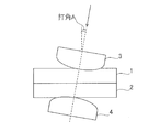
- a high current welding current is applied between the upper and lower electrodes while pressing with a pair of electrodes 3 and 4 from above and below with two or more stacked steel plates 1 and 2 sandwiched between them.
- This is a method of joining by energizing for a short time.
- a spot-like welded portion 5 is obtained using resistance heat generated by flowing a high-current welding current.
- This spot-like welded portion 5 is called a nugget and is a portion where both steel plates 1 and 2 are melted and solidified at the contact points of the steel plates when an electric current is passed through the stacked steel plates. Are joined together.
- the surface-treated steel sheet is a zinc plating typified by electrogalvanizing or hot dip galvanizing (including galvannealed alloying), or a zinc alloy containing elements such as aluminum and magnesium in addition to zinc.
- the steel plate which has metal plating layers, such as on the surface of a base material (underlying steel plate). Since the melting point of zinc plating or zinc alloy plating is lower than the melting point of the base material of the surface-treated steel sheet, there are the following problems.
- cracks in the welded portion occur when the low melting point metal plating layer on the surface of the steel sheet melts during welding, and when the tensile stress due to electrode pressure, thermal expansion and contraction of the steel sheet is applied to the welded portion,
- the melting point metal is a crack caused by so-called liquid metal embrittlement that penetrates into the crystal grain boundary of the base material of the surface-treated steel sheet and lowers the grain boundary strength to cause cracking.
- the occurrence positions of cracks are various, such as the surface of the steel plates 1 and 2 on the side in contact with the electrodes 3 and 4 as shown in FIG. 1 and the surface of the steel plates 1 and 2 on the side in contact with the steel plates.
- the composition of a steel sheet as a plate assembly is a specific range of composition, specifically, by weight, C: 0.003% to 0.01%, Mn: 0.05 to 0.5%, P: 0.02% or less, sol.Al: 0.1% or less, Ti: 48 ⁇ (N / 14) to 48 ⁇ ⁇ (N / 14) + (S / 32) ⁇ %, Nb: 93 ⁇ (C / 12) It has been proposed to have a composition comprising -0.1%, B: 0.0005-0.003%, N: 0.01% or less, Ni: 0.05% or less, the balance Fe and inevitable impurities.
- Patent Document 2 is characterized in that, in spot welding of a high-strength plated steel sheet, spot welding is performed by setting a welding energization time and a holding time after welding energization so as to satisfy the following conditions (1) and (2). A spot welding method of high strength plated steel sheet is proposed.
- the energization pattern is a multi-stage energization of three or more stages, and an appropriate current range ( ⁇ I: a current range in which a nugget having a desired nugget diameter or more and a molten residual thickness of 0.05 mm or more can be stably formed).
- ⁇ I a current range in which a nugget having a desired nugget diameter or more and a molten residual thickness of 0.05 mm or more can be stably formed.
- a method has been proposed in which welding conditions such as energization time and welding current are adjusted so as to be 1.0 kA or more, preferably 2.0 kA or more, and a cooling time is provided between the stages. JP-A-10-195597 JP 2003-103377 A JP 2003-236676 A
- Patent Document 1 since it is necessary to limit the amount of alloying elements in the steel sheet, there is a problem that the use of a steel sheet that satisfies the required performance is limited. In a situation where alloying is advanced, its application is extremely limited.
- Patent Document 2 proposes only a crack suppression method when an excessive welding current that causes scattering is set, and does not mention cracking in a state where no scattering occurs.
- Patent Document 3 has a problem that many man-hours are required for optimizing the welding conditions, and it cannot be applied to steel plates and plate assemblies in which it is difficult to ensure an appropriate current range.
- Patent Documents 2 and 3 since the influence of the angle of impact of the electrode has not been studied, there are cases where the countermeasure is insufficient in consideration of the implementation work at the time of automobile assembly.
- the present invention has been made in view of the circumstances as described above, and provides a resistance spot welding method and a welding member manufacturing method capable of suppressing the occurrence of cracks in a weld according to the angle of attack, regardless of the steel type.
- the purpose is to propose.
- the inventors have made extensive studies in order to achieve the above object. Cracks that occur during welding also occur in a range of welding conditions where no scattering occurs. The occurrence is affected by various factors, but in particular, it has been found that the impact angle A (degree) during welding (the angle at which the electrode tilts with respect to the steel sheet, FIG. 2) is greatly affected. And the knowledge that a crack can be suppressed by adjusting appropriately the pressurization holding time (henceforth a hold time) after completion
- the striking angle means an angle at which the electrode is inclined with respect to the steel plate shown in FIG. 2, that is, an “angle formed between the electrode pressing force direction and the steel plate thickness direction”.
- the direction of electrode pressing force is indicated by an arrow in the spot welding diagram described in 4.2.1 of JIS Z 3001-6: 2013, and is also indicated by an arrow in FIG. .
- the effect of the present invention on cracks that occur during welding cannot be simply explained because various factors affect it in a complicated manner, but the basic mechanism is considered as follows.
- the cause of cracks in the welded part is that the tensile stress described below occurs when the plated metal of the surface-treated steel sheet that has reached a high temperature is in contact with the base material of the surface-treated steel sheet (underlying steel sheet). Is mentioned.
- This tensile stress has a region where the electrode is locally increased when the electrode is separated from the steel plate after the end of welding.
- the present invention is based on the above findings, and the gist of the present invention is as follows. [1] In a resistance spot welding method in which a plate assembly in which a plurality of steel plates are overlapped is sandwiched between a pair of electrodes, and energized while being pressed and joined.
- At least one of the plurality of steel plates is a surface-treated steel plate having a metal plating layer
- Pressurization holding time after energization is H (ms)
- electrode striking angle is A (degrees)
- the thickness of the largest steel plate is t (mm) among the plurality of steel plates
- T tensile strength
- F applied pressure
- At least one of the plurality of steel plates is a surface-treated steel plate having a metal plating layer, and the melting point of the metal plating layer is lower than the melting point of the base material of the surface-treated steel plate,
- Pressurization holding time after energization is H (ms)
- electrode striking angle is A (degrees)
- the thickness of the largest steel plate is t (mm) among the plurality of steel plates
- T tensile strength of a steel plate with high tensile strength
- F (N) the applied pressure
- the present invention it is possible to provide a resistance spot welding method capable of suppressing the occurrence of cracks in a welded portion regardless of the steel type. By using this spot welding method, cracks in the welded portion are reduced. A welding member can be manufactured.
- the present invention is a resistance spot welding method in which a plate assembly in which a plurality of steel plates are overlapped is sandwiched between a pair of electrodes and is energized and joined while being pressed, and includes a step of holding the applied pressure after the energization is completed. is there.
- the present invention is applied to a resistance spot welding method for a plate set in which at least one of the plurality of steel plates in the plate set is a surface-treated steel plate having a metal plating layer.
- a welding apparatus that can be used in the resistance spot welding method of the present invention, it is possible to use a welding apparatus that includes a pair of upper and lower electrodes and that can arbitrarily control the pressure and welding current during welding.
- the pressurizing mechanism air cylinder, servo motor, etc.
- type stationary, robot gun, etc.
- electrode shape, etc. of the welding apparatus are not particularly limited.
- Examples of the electrode tip include DR type (dome radius type), R diameter (radius type), and D type (dome type) described in JIS C 9304: 1999.
- the tip diameter of the electrode is, for example, 4 mm to 16 mm.
- the pressurization holding time after the end of energization is H (ms)
- the electrode striking angle is A (degrees)
- the thickness of the steel plate having the largest thickness among the plurality of steel plates is t (mm)
- the tensile strength of the steel plate with the largest tensile strength among the multiple steel plates is T (MPa) and the applied pressure is F (N)
- T MPa
- F N
- the present invention is When 0.2 ⁇ A ⁇ 1, 2 ⁇ A ⁇ (t ⁇ T / F) 1/2 ⁇ H When 1 ⁇ A ⁇ 10 (3 ⁇ A ⁇ 1) ⁇ (t ⁇ T / F) 1/2 ⁇ H When 10 ⁇ A ⁇ 20 (A + 19) ⁇ (t ⁇ T / F) 1/2 ⁇ H Satisfy the relationship.
- the hold time H is a pressure holding time after the end of energization, and is the time from the end of energization to the time when the electrode is released from the steel plate.
- the time when the electrode is released from the steel plate is when the electrode starts to leave the steel plate.
- the applied pressure F is the applied pressure at the end of energization, and is the applied pressure at the end of the final energization when energizing a plurality of times.
- the applied pressure during energization may or may not be constant.
- the electrode hitting angle A is the hitting angle at the start of energization. Note that the pressure F in the step of holding the pressure after the end of energization in this specification is an actual measurement value.
- the temperature of the welded portion at the time of tensile stress generation can be reduced.
- the liquid metal embrittlement of the metal plating layer (for example, zinc) can be prevented.
- the plated metal melts once when heated by energization for welding, but if the hold time is secured above a certain level according to the striking angle and the temperature of the weld is lowered, the subsequent occurrence of tensile stress Since the plated metal is already solidified (that is, when the electrode is released from the steel plate), the plated metal does not enter the crystal grain boundaries, and the occurrence of cracks can be reduced.
- the hold time since spot welding is performed in a state where the electrode is always water-cooled, if the hold time is lengthened, the cooling rate is increased, and the temperature of the welded portion when the tensile stress is generated can be lowered. If only solidification of the metal plating layer is taken into consideration, the hold time may be lengthened, but in the present invention, it is not necessary to make the hold time longer than necessary, for example, by setting the hold time near the lower limit value that satisfies the equation. This can be a resistance spot welding method in which the occurrence of this is suppressed and the productivity is good.
- the hold time H can be set to 30 ms or less.
- the hit angle in the range where the hit angle is 0 degree or more and less than 1 degree, the bending stress applied to the welded portion by the hit angle is relatively small. For this reason, the tensile stress which generate
- the striking angle In the range where the striking angle is 1 degree or more and less than 10 degrees, as the striking angle increases, the increase in the tensile stress generated in the weld after electrode release becomes significant. For this reason, it is necessary to increase the hold time in accordance with the increase margin of the tensile stress.
- the hitting angle of 1 degree is substantially 1.0 degree.
- the tensile stress generated in the welded portion becomes very large.
- cracking can be prevented by releasing the electrode after the metal plating once melted is completely solidified. It is considered that cracking does not occur unless the molten metal plating remains.
- the hitting angle is in the range of 10 degrees or more and less than 20 degrees, a sufficient holding time is secured for the molten metal plating to solidify, so the increase in the holding time with respect to the hitting angle may be small.
- the contact area between the electrode and the steel sheet is generally reduced when the striking angle is increased, the cooling rate of the welded portion tends to decrease. Therefore, it is desirable to increase the hold time by a certain amount or more according to the hitting angle. A hitting angle of 20 degrees or more is not practical.
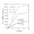
- FIG. 3 shows an image diagram of the above.
- FIG. 3 is a diagram showing respective equations when the plate thickness t is 2.5 mm, the tensile strength T is 1500 MPa, and the pressing force F is 2500N.
- the upper limit of the hold time H is desirably 2000 ms.
- the tensile strength T of the steel plate is not particularly limited, and is, for example, 250 MPa to 2000 MPa.
- the steel plate has a tensile strength of 590 MPa or more, more effectiveness can be obtained.
- a greater effect can be obtained when at least one of the steel plates in the plate set has a tensile strength of 780 MPa or more.
- the center of the welding point is the center of the nugget at the joint surface between the welded steel sheet and the steel sheet.
- the shape of the nugget at the joint surface between the welded steel plates becomes a circle when the hitting angle A is 0, but becomes an ellipse when the hitting angle A> 0, and the center of the ellipse is the major axis and the minor axis. Is the intersection of In the case of a shape other than a circle or ellipse, the center-to-center distance L is obtained with the center of gravity of the shape on the joint surface as the center.
- the center distance L is preferably set to 8.0 mm or more. More preferably, the center-to-center distance L is more preferably 10.0 mm or more.
- the steel type of the steel plate used in the present invention is not particularly limited.
- the manufacturing method of a steel plate is arbitrary, such as cold rolling and hot rolling, and the structure of the steel plate is also arbitrary. Moreover, even if the hot-pressed steel plate is used for the steel plate of the plate set used in the present invention, there is no problem. Further, the thickness of the steel plate is not particularly limited as long as it can be used for a general automobile body (about 0.5 to 4.0 mm).
- the composition of the metal plating layer of the surface-treated steel sheet having a metal plating layer is also arbitrary. As described above, cracks in the weld are partly due to the melting of the low melting point metal plating layer. large.
- the melting point of the base material (underlying steel plate) is, for example, 1400 to 1570 ° C., and the melting point of the metal plating layer is, for example, 300 to 1200 ° C. If it is a general plating layer, melting
- the metal plating layer include a Zn-based plating layer and an Al-based plating layer. For members that require corrosion resistance, Zn-based plating is superior to Al-based plating.
- the corrosion rate of the base steel sheet can be reduced by the sacrificial anticorrosive action of zinc Zn.
- Zn-based plating include general hot-dip galvanizing (GI), alloyed hot-dip galvanizing (GA), electrogalvanizing (EG), and Zn—Ni-based plating (for example, Zn—containing 10 to 25 mass% of Ni— Ni-based plating), Zn-Al-based plating, Zn-Mg-based plating, Zn-Al-Mg-based plating, and the like.
- the Al plating include Al—Si plating (for example, Al—Si plating containing 10 to 20 mass% Si). The amount of plating applied is arbitrary, but from the viewpoint of weldability, it is desirable that the amount be 120 g / m 2 or less per side.
- the plate set in the present invention is not particularly limited, and a plurality of the same type steel plates may be stacked or a plurality of different types of steel plates may be stacked. Further, there is no problem even if the plate thickness of each steel plate is different, and a combination of a steel plate having a metal plating layer having a melting point lower than that of the steel plate and a steel plate having no metal plating layer may be used.
- the current value, energization time, and applied pressure during energization may be constant, but need not be constant.
- the current value and applied pressure may be changed in two or more stages, and the cooling time may be set between each stage. It may be provided. Further, there is no problem even if a control method is used in which parameters such as resistance value and voltage value during welding are monitored and the current value and energization time are changed according to the fluctuation.
- the following shows the preferred range of current value, energization time, and applied pressure during energization when welding is performed with one-stage energization.
- the current value during energization is preferably 10 kA or less, for example.
- the energization time is preferably 200 ms to 700 ms, for example.
- the applied pressure during energization is preferably 2000N to 7000N, for example.
- the upper limit of a suitable current value extends to 15 kA.
- the upper limit of a suitable energization time extends to 1000 ms.
- the energization time in the case of multistage energization is the sum of the energization times of each stage.
- the method for manufacturing a welding member of the present invention includes a step of superimposing a plurality of steel plates including at least one surface-treated steel plate having a metal plating layer to obtain a plate set, and the obtained plate set is subjected to the above resistance. And a step of welding by a spot welding method.
- the resistance spot welding method When welding is performed using the resistance spot welding method, the occurrence of cracks in the welded portion can be suppressed, so that a welded member with reduced cracking in the welded portion can be manufactured.
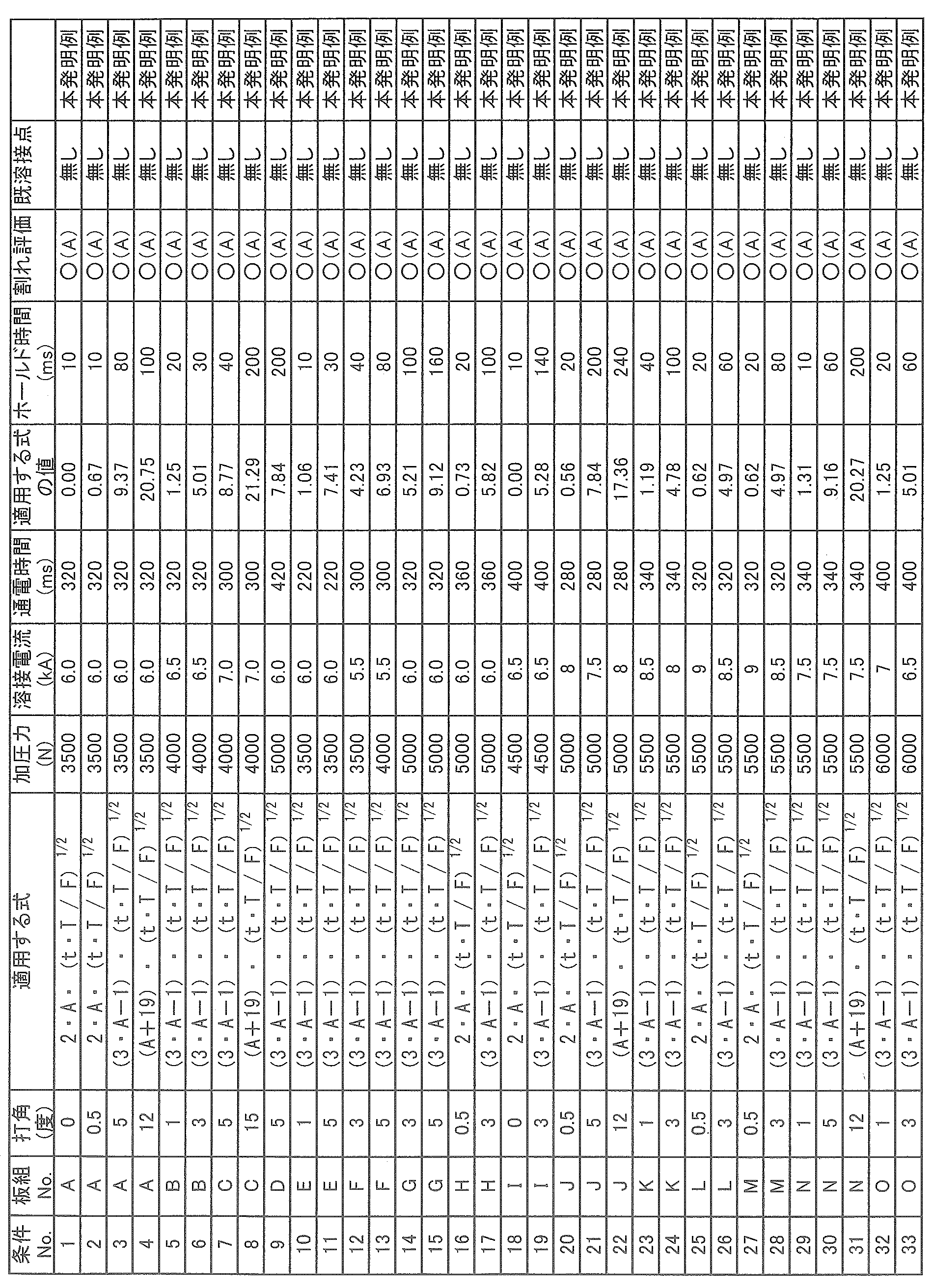
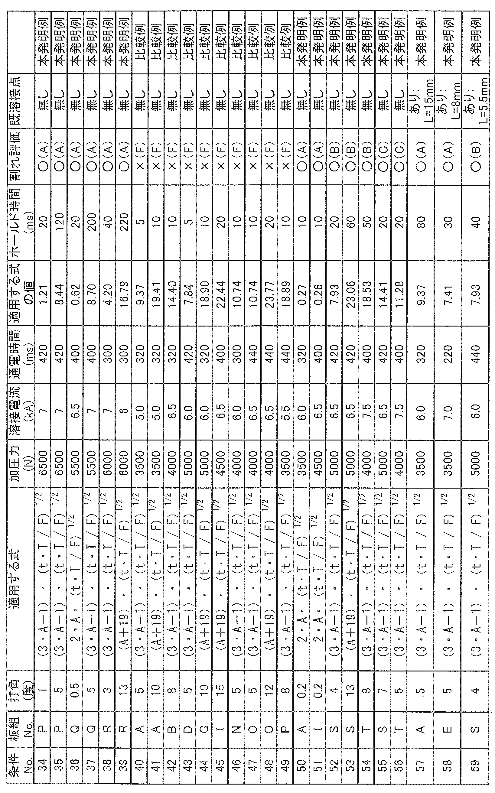
- Examples of the present invention are shown below. Resistance spot welding was performed on the two-layer or three-layer stacks shown in Table 1 under the conditions shown in Table 2-1 and Table 2-2, joints were manufactured, and welded members were manufactured.
- the melting point of the base material of each test material in this example is in the range of 1400 to 1570 ° C.
- the melting points of hot dip galvanizing (GI) and alloyed hot dip galvanizing (GA) are 400 to 500 ° C. and 600 ° C., respectively. It is in the range of ⁇ 950 ° C.
- the tensile strength shown in Table 1 was determined by preparing a JIS No.
- FIG. 5 shows a test method when the steel plates 1 and 2 are overlapped to form a two-layered plate set
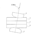
- FIG. 6 shows a three-layered plate set by overlapping the steel plates 1, 2 and 6. The test method in the case where it did is shown.
- “None” is described in the “Pre-weld point” column in Tables 2-1 and 2-2.
- the welding device used was an inverter DC resistance spot welding device, and the electrode was a DR type and a chromium copper electrode having a tip diameter of 6 mm.
- the energization was performed once, and the current value during welding (welding current) was a constant value.
- the hitting angle was the hitting angle at the start of energization.
- the applied pressure is the applied pressure at the end of energization, and was constant during the process of energizing and maintaining the applied pressure at the end of energization. Resistance spot welding was performed at room temperature, and the electrodes were always cooled in water.
Landscapes
- Engineering & Computer Science (AREA)
- Mechanical Engineering (AREA)
- Resistance Welding (AREA)
Abstract
Description
0.25・(10・t+2)/50≦WT≦0.50・(10・t+2)/50 ・・(1)
300-500・t+250・t2≦HT ・・(2)
ただし、t:板厚(mm)、WT:溶接通電時間(ms)、HT:溶接通電後の保持時間(ms)
また、特許文献2では、鋼板の板厚に応じて通電時間および通電後の電極の保持時間を適切に設定し、鋼板中の合金元素量が一定以下となる高張力亜鉛めっき鋼板を用いて溶接を行うことも提案されている。
[1] 複数の鋼板を重ね合わせた板組を、一対の電極によって挟み、加圧しながら通電して接合する抵抗スポット溶接方法において、
複数の鋼板のうち少なくとも1枚は、金属めっき層を有する表面処理鋼板であり、
通電終了後の加圧力保持時間をH(ms)、電極の打角をA(度)、複数の鋼板のうち最も板厚が大きい鋼板の板厚をt(mm)、複数の鋼板のうち最も引張強度が大きい鋼板の引張強度をT(MPa)、加圧力をF(N)としたとき、
0≦A<1 の場合に 2・A・(t・T / F)1/2 ≦ H
1≦A<10 の場合に (3・A-1)・(t・T / F)1/2 ≦ H
10≦A<20 の場合に (A+19)・(t・T / F)1/2 ≦ H
の関係を満たす抵抗スポット溶接方法。
[2] 複数の鋼板を重ね合わせた板組を、一対の電極によって挟み、加圧しながら通電して接合する抵抗スポット溶接方法において、
複数の鋼板のうち少なくとも1枚は、金属めっき層を有する表面処理鋼板であり、該金属めっき層の融点は、表面処理鋼板の母材の融点よりも低く、
通電終了後の加圧力保持時間をH(ms)、電極の打角をA(度)、複数の鋼板のうち最も板厚が大きい鋼板の板厚をt(mm)、複数の鋼板のうち最も引張強度が大きい鋼板の引張強度をT(MPa)、加圧力をF(N)としたとき、
0≦A<1 の場合に 2・A・(t・T / F)1/2 ≦ H
1≦A<10 の場合に (3・A-1)・(t・T / F)1/2 ≦ H
10≦A<20 の場合に (A+19)・(t・T / F)1/2 ≦ H
の関係を満たす抵抗スポット溶接方法。
[3] Aが0.2以上である[1]または[2]に記載の抵抗スポット溶接方法。
[4] 前記金属めっき層が、Zn系めっき層またはAl系めっき層である[1]~[3]のいずれか一つに記載の抵抗スポット溶接方法。
[5] 複数の鋼板のうち少なくとも1枚は、引張強度が590MPa以上である[1]~[4]のいずれか一つに記載の抵抗スポット溶接方法。
[6] 溶接点の周囲に、既溶接点が1点以上存在する場合、前記溶接点と最も近い既溶接点との中心間距離Lを6.0mm以上として溶接する[1]~[5]のいずれか一つに記載の抵抗スポット溶接方法。
[7] 金属めっき層を有する表面処理鋼板を少なくとも1枚含む複数の鋼板を重ね合わせて板組を得る工程と、
得られた板組を[1]~[6]のいずれか一つに記載の抵抗スポット溶接方法により溶接する工程とを有する溶接部材の製造方法。
0≦A<1 の場合に 2・A・(t・T / F)1/2 ≦ H
1≦A<10 の場合に (3・A-1)・(t・T / F)1/2 ≦ H
10≦A<20 の場合に (A+19)・(t・T / F)1/2≦ H
の関係を満たす。また、上記式において打角Aが0.2(度)以上の場合を具体的に記載すると、本発明は、
0.2≦A<1 の場合に 2・A・(t・T / F)1/2≦ H
1≦A<10 の場合に (3・A-1)・(t・T / F)1/2 ≦ H
10≦A<20 の場合に (A+19)・(t・T / F)1/2≦ H
の関係を満たす。
0≦A<1 の場合に 3・A・(t・T / F)1/2≦ H
1≦A<10 の場合に (8・A-5)・(t・T / F)1/2 ≦ H
10≦A<20 の場合に (A+65)・(t・T / F)1/2≦ H
の関係を満たすことが好適である。さらに望ましくは、
0≦A<1 の場合に 6・A・(t・T / F)1/2≦ H
1≦A<10 の場合に (12・A-6)・(t・T / F)1/2 ≦ H
10≦A<20 の場合に (A+104)・(t・T / F)1/2≦ H
の関係を満たすことがより好適である。
0.2≦A<1 の場合に 3・A・(t・T / F)1/2 ≦ H
1≦A<10 の場合に (8・A-5)・(t・T / F)1/2 ≦ H
10≦A<20 の場合に (A+65)・(t・T / F)1/2≦ H
の関係を満たすことが好適であり、さらに望ましくは、
0.2≦A<1 の場合に 6・A・(t・T / F)1/2 ≦ H
1≦A<10 の場合に (12・A-6)・(t・T / F)1/2 ≦ H
10≦A<20 の場合に (A+104)・(t・T / F)1/2≦ H
の関係を満たすことがより好適である。
A:10体全ての継手で割れ無し
B:10体の内1体に長さ10μm未満の割れありで、且つ、10体全ての継手で長さ10μm以上の割れ無し
C:10体の内2体に長さ10μm未満の割れありで、且つ、10体全ての継手で長さ10μm以上の割れ無し
F:10体の内3体以上に長さ10μm未満の割れあり、或いは、10体の内1体以上に長さ10μm以上の割れあり
本発明を満たすようにホールド時間を設定した継手(本発明例)は、散り発生の有無にかかわらず全てA~Cのいずれかの評価(○)であった。

3、4 電極
5 溶接部(ナゲット)
Claims (7)
- 複数の鋼板を重ね合わせた板組を、一対の電極によって挟み、加圧しながら通電して接合する抵抗スポット溶接方法において、
複数の鋼板のうち少なくとも1枚は、金属めっき層を有する表面処理鋼板であり、
通電終了後の加圧力保持時間をH(ms)、電極の打角をA(度)、複数の鋼板のうち最も板厚が大きい鋼板の板厚をt(mm)、複数の鋼板のうち最も引張強度が大きい鋼板の引張強度をT(MPa)、加圧力をF(N)としたとき、
0≦A<1 の場合に 2・A・(t・T / F)1/2 ≦ H
1≦A<10 の場合に (3・A-1)・(t・T / F)1/2 ≦ H
10≦A<20 の場合に (A+19)・(t・T / F)1/2 ≦ H
の関係を満たす抵抗スポット溶接方法。 - 複数の鋼板を重ね合わせた板組を、一対の電極によって挟み、加圧しながら通電して接合する抵抗スポット溶接方法において、
複数の鋼板のうち少なくとも1枚は、金属めっき層を有する表面処理鋼板であり、該金属めっき層の融点は、表面処理鋼板の母材の融点よりも低く、
通電終了後の加圧力保持時間をH(ms)、電極の打角をA(度)、複数の鋼板のうち最も板厚が大きい鋼板の板厚をt(mm)、複数の鋼板のうち最も引張強度が大きい鋼板の引張強度をT(MPa)、加圧力をF(N)としたとき、
0≦A<1 の場合に 2・A・(t・T / F)1/2 ≦ H
1≦A<10 の場合に (3・A-1)・(t・T / F)1/2 ≦ H
10≦A<20 の場合に (A+19)・(t・T / F)1/2 ≦ H
の関係を満たす抵抗スポット溶接方法。 - Aが0.2以上である請求項1または2に記載の抵抗スポット溶接方法。
- 前記金属めっき層が、Zn系めっき層またはAl系めっき層である請求項1~3のいずれか一項に記載の抵抗スポット溶接方法。
- 複数の鋼板のうち少なくとも1枚は、引張強度が590MPa以上である請求項1~4のいずれか一項に記載の抵抗スポット溶接方法。
- 溶接点の周囲に、既溶接点が1点以上存在する場合、前記溶接点と最も近い既溶接点との中心間距離Lを6.0mm以上として溶接する請求項1~5のいずれか一項に記載の抵抗スポット溶接方法。
- 金属めっき層を有する表面処理鋼板を少なくとも1枚含む複数の鋼板を重ね合わせて板組を得る工程と、
得られた板組を請求項1~6のいずれか一項に記載の抵抗スポット溶接方法により溶接する工程とを有する溶接部材の製造方法。
Priority Applications (6)
| Application Number | Priority Date | Filing Date | Title |
|---|---|---|---|
| JP2016567447A JP6168246B1 (ja) | 2015-08-27 | 2016-08-23 | 抵抗スポット溶接方法および溶接部材の製造方法 |
| KR1020187005582A KR102028435B1 (ko) | 2015-08-27 | 2016-08-23 | 저항 스폿 용접 방법 및 용접 부재의 제조 방법 |
| MX2018002382A MX2018002382A (es) | 2015-08-27 | 2016-08-23 | Metodo de soldadura por punto de resistencia y metodo de produccion de miembro soldado. |
| EP16838805.6A EP3342524B1 (en) | 2015-08-27 | 2016-08-23 | Resistance spot welding method and method for manufacturing welded member |
| US15/755,118 US10835986B2 (en) | 2015-08-27 | 2016-08-23 | Resistance spot welding method and welded member production method |
| CN201680049747.3A CN107921572B (zh) | 2015-08-27 | 2016-08-23 | 电阻点焊方法及焊接构件的制造方法 |
Applications Claiming Priority (2)
| Application Number | Priority Date | Filing Date | Title |
|---|---|---|---|
| JP2015167935 | 2015-08-27 | ||
| JP2015-167935 | 2015-08-27 |
Publications (1)
| Publication Number | Publication Date |
|---|---|
| WO2017033455A1 true WO2017033455A1 (ja) | 2017-03-02 |
Family
ID=58101131
Family Applications (1)
| Application Number | Title | Priority Date | Filing Date |
|---|---|---|---|
| PCT/JP2016/003811 Ceased WO2017033455A1 (ja) | 2015-08-27 | 2016-08-23 | 抵抗スポット溶接方法および溶接部材の製造方法 |
Country Status (7)
| Country | Link |
|---|---|
| US (1) | US10835986B2 (ja) |
| EP (1) | EP3342524B1 (ja) |
| JP (1) | JP6168246B1 (ja) |
| KR (1) | KR102028435B1 (ja) |
| CN (1) | CN107921572B (ja) |
| MX (1) | MX2018002382A (ja) |
| WO (1) | WO2017033455A1 (ja) |
Cited By (4)
| Publication number | Priority date | Publication date | Assignee | Title |
|---|---|---|---|---|
| JP2021109244A (ja) * | 2020-01-15 | 2021-08-02 | 日本製鉄株式会社 | 抵抗スポット溶接における打角測定方法、抵抗スポット溶接継手の製造方法及び抵抗スポット溶接装置 |
| WO2021172080A1 (ja) | 2020-02-25 | 2021-09-02 | 株式会社神戸製鋼所 | 抵抗スポット溶接方法 |
| JP2022015124A (ja) * | 2020-07-08 | 2022-01-21 | フタバ産業株式会社 | 抵抗スポット溶接方法及び抵抗スポット溶接装置 |
| KR20240051301A (ko) | 2021-10-15 | 2024-04-19 | 가부시키가이샤 고베 세이코쇼 | 저항 스폿 용접 장치 및 저항 스폿 용접 방법 |
Families Citing this family (3)
| Publication number | Priority date | Publication date | Assignee | Title |
|---|---|---|---|---|
| RU2689293C1 (ru) * | 2015-09-03 | 2019-05-24 | Ниппон Стил Энд Сумитомо Метал Корпорейшн | Способ точечной сварки |
| CA3012818A1 (en) * | 2016-02-05 | 2017-08-10 | Nippon Steel & Sumitomo Metal Corporation | Fracture prediction method and device, program, and recording medium |
| CN115773832A (zh) * | 2022-08-31 | 2023-03-10 | 麦克传感器股份有限公司 | 一种全封焊型压力传感器及封装方法 |
Citations (6)
| Publication number | Priority date | Publication date | Assignee | Title |
|---|---|---|---|---|
| JPH0699283A (ja) * | 1992-09-18 | 1994-04-12 | Kawasaki Steel Corp | 熱硬化性樹脂制振鋼板の短間隔連続スポット溶接方法及び溶接機 |
| JP2003019571A (ja) * | 2001-07-06 | 2003-01-21 | Nitta Ind Corp | スポット溶接電極の面直度センサ並びに面直度計測方法及び装置 |
| JP2006218538A (ja) * | 2005-02-14 | 2006-08-24 | Fuji Heavy Ind Ltd | 面直ゲージ、該面直ゲージを用いた溶接ガンの被溶接ワークに対する面直設定方法 |
| JP2011005544A (ja) * | 2009-05-27 | 2011-01-13 | Nippon Steel Corp | 高強度鋼板のスポット溶接方法 |
| JP2013071124A (ja) * | 2011-09-26 | 2013-04-22 | Honda Motor Co Ltd | スポット溶接方法及びスポット溶接装置 |
| WO2015049998A1 (ja) * | 2013-10-04 | 2015-04-09 | Jfeスチール株式会社 | 抵抗スポット溶接方法 |
Family Cites Families (11)
| Publication number | Priority date | Publication date | Assignee | Title |
|---|---|---|---|---|
| JPH10195597A (ja) | 1996-11-14 | 1998-07-28 | Sumitomo Metal Ind Ltd | 接合性に優れた薄鋼板 |
| US6232572B1 (en) * | 1998-04-20 | 2001-05-15 | Nissan Motor Co., Ltd. | Spot welding control system and control method |
| JP2003103377A (ja) | 2001-09-27 | 2003-04-08 | Nippon Steel Corp | 高強度めっき鋼板のスポット溶接方法 |
| JP3849539B2 (ja) | 2002-02-19 | 2006-11-22 | Jfeスチール株式会社 | 高張力亜鉛系めっき鋼板のスポット溶接方法 |
| DE102005001341B3 (de) * | 2005-01-11 | 2006-10-05 | Kuka Schweissanlagen Gmbh | Verfahren und Vorrichtung zum elektrischen Punktschweißen |
| WO2011025015A1 (ja) | 2009-08-31 | 2011-03-03 | 新日本製鐵株式会社 | スポット溶接継手およびスポット溶接方法 |
| US9969026B2 (en) * | 2011-08-25 | 2018-05-15 | GM Global Technology Operations LLC | Weld schedule for resistance spot welding of aluminum alloy workpieces |
| CA2873854C (en) * | 2012-05-18 | 2018-02-06 | Honda Motor Co., Ltd. | Switching electrode and resistance welding device using same, spot welding device and spot welding method |
| EP2965848B1 (en) | 2013-03-08 | 2019-08-14 | JFE Steel Corporation | Resistance spot welding method |
| JP6094306B2 (ja) * | 2013-03-26 | 2017-03-15 | 新日鐵住金株式会社 | 亜鉛系めっき鋼板の抵抗スポット溶接方法 |
| US20160082543A1 (en) * | 2013-06-05 | 2016-03-24 | Nippon Steel & Sumitomo Metal Corporation | Spot-welded joint and spot welding method |
-
2016
- 2016-08-23 KR KR1020187005582A patent/KR102028435B1/ko active Active
- 2016-08-23 JP JP2016567447A patent/JP6168246B1/ja active Active
- 2016-08-23 WO PCT/JP2016/003811 patent/WO2017033455A1/ja not_active Ceased
- 2016-08-23 US US15/755,118 patent/US10835986B2/en active Active
- 2016-08-23 MX MX2018002382A patent/MX2018002382A/es unknown
- 2016-08-23 CN CN201680049747.3A patent/CN107921572B/zh active Active
- 2016-08-23 EP EP16838805.6A patent/EP3342524B1/en active Active
Patent Citations (6)
| Publication number | Priority date | Publication date | Assignee | Title |
|---|---|---|---|---|
| JPH0699283A (ja) * | 1992-09-18 | 1994-04-12 | Kawasaki Steel Corp | 熱硬化性樹脂制振鋼板の短間隔連続スポット溶接方法及び溶接機 |
| JP2003019571A (ja) * | 2001-07-06 | 2003-01-21 | Nitta Ind Corp | スポット溶接電極の面直度センサ並びに面直度計測方法及び装置 |
| JP2006218538A (ja) * | 2005-02-14 | 2006-08-24 | Fuji Heavy Ind Ltd | 面直ゲージ、該面直ゲージを用いた溶接ガンの被溶接ワークに対する面直設定方法 |
| JP2011005544A (ja) * | 2009-05-27 | 2011-01-13 | Nippon Steel Corp | 高強度鋼板のスポット溶接方法 |
| JP2013071124A (ja) * | 2011-09-26 | 2013-04-22 | Honda Motor Co Ltd | スポット溶接方法及びスポット溶接装置 |
| WO2015049998A1 (ja) * | 2013-10-04 | 2015-04-09 | Jfeスチール株式会社 | 抵抗スポット溶接方法 |
Cited By (7)
| Publication number | Priority date | Publication date | Assignee | Title |
|---|---|---|---|---|
| JP2021109244A (ja) * | 2020-01-15 | 2021-08-02 | 日本製鉄株式会社 | 抵抗スポット溶接における打角測定方法、抵抗スポット溶接継手の製造方法及び抵抗スポット溶接装置 |
| JP7575673B2 (ja) | 2020-01-15 | 2024-10-30 | 日本製鉄株式会社 | 抵抗スポット溶接における打角測定方法、抵抗スポット溶接継手の製造方法及び抵抗スポット溶接装置 |
| WO2021172080A1 (ja) | 2020-02-25 | 2021-09-02 | 株式会社神戸製鋼所 | 抵抗スポット溶接方法 |
| KR20220121883A (ko) | 2020-02-25 | 2022-09-01 | 가부시키가이샤 고베 세이코쇼 | 저항 스폿 용접 방법 |
| JP2022015124A (ja) * | 2020-07-08 | 2022-01-21 | フタバ産業株式会社 | 抵抗スポット溶接方法及び抵抗スポット溶接装置 |
| JP7208193B2 (ja) | 2020-07-08 | 2023-01-18 | フタバ産業株式会社 | 抵抗スポット溶接方法及び抵抗スポット溶接装置 |
| KR20240051301A (ko) | 2021-10-15 | 2024-04-19 | 가부시키가이샤 고베 세이코쇼 | 저항 스폿 용접 장치 및 저항 스폿 용접 방법 |
Also Published As
| Publication number | Publication date |
|---|---|
| US20180257165A1 (en) | 2018-09-13 |
| CN107921572B (zh) | 2021-03-05 |
| EP3342524A4 (en) | 2019-05-01 |
| KR20180031033A (ko) | 2018-03-27 |
| MX2018002382A (es) | 2018-04-11 |
| JPWO2017033455A1 (ja) | 2017-08-31 |
| US10835986B2 (en) | 2020-11-17 |
| EP3342524B1 (en) | 2023-09-20 |
| CN107921572A (zh) | 2018-04-17 |
| EP3342524A1 (en) | 2018-07-04 |
| KR102028435B1 (ko) | 2019-10-04 |
| JP6168246B1 (ja) | 2017-07-26 |
Similar Documents
| Publication | Publication Date | Title |
|---|---|---|
| JP6278154B2 (ja) | 抵抗スポット溶接方法および溶接部材の製造方法 | |
| JP6168246B1 (ja) | 抵抗スポット溶接方法および溶接部材の製造方法 | |
| JP6372639B1 (ja) | 抵抗スポット溶接方法 | |
| TWI601588B (zh) | Resistance point welding method | |
| JP6108018B2 (ja) | スポット溶接方法 | |
| TWI622445B (zh) | 點熔接方法 | |
| JP6108017B2 (ja) | スポット溶接方法 | |
| JP7364113B2 (ja) | 抵抗スポット溶接部材およびその抵抗スポット溶接方法 | |
| JP7047535B2 (ja) | 抵抗スポット溶接方法 | |
| JP7545096B2 (ja) | 抵抗スポット溶接継手および抵抗スポット溶接継手の製造方法 | |
| KR20150143818A (ko) | 스폿 용접 조인트 및 스폿 용접 방법 | |
| JP7508031B1 (ja) | 抵抗スポット溶接方法 | |
| WO2024063009A1 (ja) | 溶接部材およびその製造方法 | |
| JP2020157358A (ja) | 亜鉛系めっき鋼板のスポット溶接方法 | |
| JP7355282B1 (ja) | 溶接継手、溶接部材およびその製造方法、ならびに、抵抗スポット溶接方法 | |
| JP7435935B1 (ja) | 溶接部材およびその製造方法 | |
| JP7355281B1 (ja) | 溶接継手、溶接部材およびその製造方法、ならびに、抵抗スポット溶接方法 | |
| WO2023233705A1 (ja) | 溶接継手、溶接部材およびその製造方法、ならびに、抵抗スポット溶接方法 | |
| WO2024063010A1 (ja) | 溶接部材およびその製造方法 |
Legal Events
| Date | Code | Title | Description |
|---|---|---|---|
| ENP | Entry into the national phase |
Ref document number: 2016567447 Country of ref document: JP Kind code of ref document: A |
|
| 121 | Ep: the epo has been informed by wipo that ep was designated in this application |
Ref document number: 16838805 Country of ref document: EP Kind code of ref document: A1 |
|
| ENP | Entry into the national phase |
Ref document number: 20187005582 Country of ref document: KR Kind code of ref document: A |
|
| WWE | Wipo information: entry into national phase |
Ref document number: 15755118 Country of ref document: US Ref document number: MX/A/2018/002382 Country of ref document: MX |
|
| NENP | Non-entry into the national phase |
Ref country code: DE |
|
| WWE | Wipo information: entry into national phase |
Ref document number: 2016838805 Country of ref document: EP |