WO2017026283A1 - 被監視者監視システムの表示装置および表示方法ならびに被監視者監視システム - Google Patents
被監視者監視システムの表示装置および表示方法ならびに被監視者監視システム Download PDFInfo
- Publication number
- WO2017026283A1 WO2017026283A1 PCT/JP2016/072000 JP2016072000W WO2017026283A1 WO 2017026283 A1 WO2017026283 A1 WO 2017026283A1 JP 2016072000 W JP2016072000 W JP 2016072000W WO 2017026283 A1 WO2017026283 A1 WO 2017026283A1
- Authority
- WO
- WIPO (PCT)
- Prior art keywords
- display
- unit
- displayed
- processing unit
- monitoring information
- Prior art date
Links
Images


Classifications
-
- G—PHYSICS
- G08—SIGNALLING
- G08B—SIGNALLING OR CALLING SYSTEMS; ORDER TELEGRAPHS; ALARM SYSTEMS
- G08B21/00—Alarms responsive to a single specified undesired or abnormal condition and not otherwise provided for
- G08B21/02—Alarms for ensuring the safety of persons
-
- G—PHYSICS
- G08—SIGNALLING
- G08B—SIGNALLING OR CALLING SYSTEMS; ORDER TELEGRAPHS; ALARM SYSTEMS
- G08B25/00—Alarm systems in which the location of the alarm condition is signalled to a central station, e.g. fire or police telegraphic systems
- G08B25/01—Alarm systems in which the location of the alarm condition is signalled to a central station, e.g. fire or police telegraphic systems characterised by the transmission medium
- G08B25/04—Alarm systems in which the location of the alarm condition is signalled to a central station, e.g. fire or police telegraphic systems characterised by the transmission medium using a single signalling line, e.g. in a closed loop
-
- A—HUMAN NECESSITIES
- A61—MEDICAL OR VETERINARY SCIENCE; HYGIENE
- A61G—TRANSPORT, PERSONAL CONVEYANCES, OR ACCOMMODATION SPECIALLY ADAPTED FOR PATIENTS OR DISABLED PERSONS; OPERATING TABLES OR CHAIRS; CHAIRS FOR DENTISTRY; FUNERAL DEVICES
- A61G12/00—Accommodation for nursing, e.g. in hospitals, not covered by groups A61G1/00 - A61G11/00, e.g. trolleys for transport of medicaments or food; Prescription lists
-
- G—PHYSICS
- G06—COMPUTING; CALCULATING OR COUNTING
- G06F—ELECTRIC DIGITAL DATA PROCESSING
- G06F3/00—Input arrangements for transferring data to be processed into a form capable of being handled by the computer; Output arrangements for transferring data from processing unit to output unit, e.g. interface arrangements
- G06F3/01—Input arrangements or combined input and output arrangements for interaction between user and computer
- G06F3/048—Interaction techniques based on graphical user interfaces [GUI]
- G06F3/0484—Interaction techniques based on graphical user interfaces [GUI] for the control of specific functions or operations, e.g. selecting or manipulating an object, an image or a displayed text element, setting a parameter value or selecting a range
- G06F3/04842—Selection of displayed objects or displayed text elements
-
- G—PHYSICS
- G08—SIGNALLING
- G08B—SIGNALLING OR CALLING SYSTEMS; ORDER TELEGRAPHS; ALARM SYSTEMS
- G08B21/00—Alarms responsive to a single specified undesired or abnormal condition and not otherwise provided for
- G08B21/02—Alarms for ensuring the safety of persons
- G08B21/04—Alarms for ensuring the safety of persons responsive to non-activity, e.g. of elderly persons
- G08B21/0407—Alarms for ensuring the safety of persons responsive to non-activity, e.g. of elderly persons based on behaviour analysis
-
- G—PHYSICS
- G08—SIGNALLING
- G08B—SIGNALLING OR CALLING SYSTEMS; ORDER TELEGRAPHS; ALARM SYSTEMS
- G08B21/00—Alarms responsive to a single specified undesired or abnormal condition and not otherwise provided for
- G08B21/02—Alarms for ensuring the safety of persons
- G08B21/04—Alarms for ensuring the safety of persons responsive to non-activity, e.g. of elderly persons
- G08B21/0438—Sensor means for detecting
- G08B21/0461—Sensor means for detecting integrated or attached to an item closely associated with the person but not worn by the person, e.g. chair, walking stick, bed sensor
-
- G—PHYSICS
- G08—SIGNALLING
- G08B—SIGNALLING OR CALLING SYSTEMS; ORDER TELEGRAPHS; ALARM SYSTEMS
- G08B21/00—Alarms responsive to a single specified undesired or abnormal condition and not otherwise provided for
- G08B21/02—Alarms for ensuring the safety of persons
- G08B21/04—Alarms for ensuring the safety of persons responsive to non-activity, e.g. of elderly persons
- G08B21/0438—Sensor means for detecting
- G08B21/0476—Cameras to detect unsafe condition, e.g. video cameras
-
- G—PHYSICS
- G08—SIGNALLING
- G08B—SIGNALLING OR CALLING SYSTEMS; ORDER TELEGRAPHS; ALARM SYSTEMS
- G08B25/00—Alarm systems in which the location of the alarm condition is signalled to a central station, e.g. fire or police telegraphic systems
- G08B25/01—Alarm systems in which the location of the alarm condition is signalled to a central station, e.g. fire or police telegraphic systems characterised by the transmission medium
- G08B25/014—Alarm signalling to a central station with two-way communication, e.g. with signalling back
-
- G—PHYSICS
- G08—SIGNALLING
- G08B—SIGNALLING OR CALLING SYSTEMS; ORDER TELEGRAPHS; ALARM SYSTEMS
- G08B25/00—Alarm systems in which the location of the alarm condition is signalled to a central station, e.g. fire or police telegraphic systems
- G08B25/01—Alarm systems in which the location of the alarm condition is signalled to a central station, e.g. fire or police telegraphic systems characterised by the transmission medium
- G08B25/08—Alarm systems in which the location of the alarm condition is signalled to a central station, e.g. fire or police telegraphic systems characterised by the transmission medium using communication transmission lines
-
- G—PHYSICS
- G16—INFORMATION AND COMMUNICATION TECHNOLOGY [ICT] SPECIALLY ADAPTED FOR SPECIFIC APPLICATION FIELDS
- G16H—HEALTHCARE INFORMATICS, i.e. INFORMATION AND COMMUNICATION TECHNOLOGY [ICT] SPECIALLY ADAPTED FOR THE HANDLING OR PROCESSING OF MEDICAL OR HEALTHCARE DATA
- G16H40/00—ICT specially adapted for the management or administration of healthcare resources or facilities; ICT specially adapted for the management or operation of medical equipment or devices
- G16H40/60—ICT specially adapted for the management or administration of healthcare resources or facilities; ICT specially adapted for the management or operation of medical equipment or devices for the operation of medical equipment or devices
- G16H40/67—ICT specially adapted for the management or administration of healthcare resources or facilities; ICT specially adapted for the management or operation of medical equipment or devices for the operation of medical equipment or devices for remote operation
-
- H—ELECTRICITY
- H04—ELECTRIC COMMUNICATION TECHNIQUE
- H04N—PICTORIAL COMMUNICATION, e.g. TELEVISION
- H04N7/00—Television systems
- H04N7/18—Closed-circuit television [CCTV] systems, i.e. systems in which the video signal is not broadcast
Definitions
- the present invention relates to a display device and a display method for a monitored person monitoring system for monitoring a monitored person to be monitored using a plurality of devices, and the monitored person monitoring system.
- Japan is an aging society, more specifically the ratio of population over 65 years old to the total population due to the improvement of living standards accompanying the post-war high economic growth, improvement of sanitary environment and improvement of medical standards, etc. It is a super-aging society with an aging rate exceeding 21%.
- the total population was about 126.5 million, while the elderly population aged 65 and over was about 25.56 million, whereas in 2020, the total population was about 124.11 million.
- the elderly population will be about 34.56 million.
- nurses who need nursing or nursing care due to illness, injury, elderly age, etc., or those who need nursing care need to take care in a normal society that is not an aging society.
- monitored person monitoring techniques for monitoring a monitored person to be monitored, such as a care recipient, have been researched and developed.
- the nurse call system disclosed in Patent Document 1 is a nurse call slave set that is installed in a bed and a patient calls a nurse, and a nurse call set that is installed in a nurse station and responds to a call by the nurse call slave set.
- a nurse call system having a nurse call parent device, a camera for imaging a patient on a bed from above the bed, and a state in which the patient wakes up from a captured image of the camera and a state in which the patient is separated from the bed State judging means for judging the occurrence of at least one of them and outputting a caution state occurrence signal, and the nurse call master unit has a notifying means for performing a notification operation upon receiving the caution state occurrence signal.
- the nurse call system transmits a captured image of the camera to the portable terminal upon receiving the attention state generation signal and a portable terminal carried by a nurse to respond to a call from the nurse call slave. Communication control means.
- the present invention has been made in view of the above-described circumstances, and its purpose is to provide a display device for a monitored person monitoring system that can promptly respond to a patient who has already been notified (coping, response). And a display method and the monitored person monitoring system.
- the display device when the sensor device detects a predetermined action in the monitored person, the detection result is newly transferred from the sensor device to the display device via the central processing unit. Received. At this time, the existing display content displayed on the display unit is maintained, a code indicating the presence of the newly received detection result is further displayed on the display unit, and a switching instruction input is accepted by the input unit. The newly received detection result is displayed on the display unit.
- FIG. 1 It is a figure which shows the structure of the monitoring person monitoring system in embodiment. It is a figure which shows the structure of the management server apparatus in the said to-be-monitored person monitoring system. It is a figure which shows the structure of the portable terminal device in the said to-be-monitored person monitoring system. It is a figure which shows the structure of the monitoring information table memorize
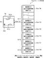
- FIG. 1 It is a figure which shows an example of the monitoring information screen displayed on the said portable terminal device which received the report from two or more different sensor apparatuses. It is a figure for demonstrating the 2nd memory
- FIG. 1 is a diagram illustrating a configuration of a monitored person monitoring system according to the embodiment.
- FIG. 2 is a diagram illustrating a configuration of the management server device in the monitored person monitoring system according to the embodiment.
- FIG. 3 is a diagram illustrating a configuration of the mobile terminal device in the monitored person monitoring system according to the embodiment.
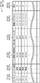
- FIG. 4 is a diagram illustrating a configuration of a monitoring information table stored in each of the management server device and the mobile terminal device in the monitored person monitoring system according to the embodiment.
- the monitored person monitoring system in the embodiment monitors a monitored person (watched person) Ob that is a monitored object (watched object) to be monitored (watched), and performs a predetermined action on the monitored person Ob.
- a sensor device that detects and reports, a display device that displays predetermined information, and the sensor device and the display device are communicably connected to each other and receives a notification of a detection result detected by the sensor device from the sensor device.
- a central processing unit that reports the detection result to the display device.
- such a monitored person monitoring system MS includes, for example, as shown in FIG. 1, one or a plurality of sensor devices SU (SU-1 to SU-4), a management server device SV, A fixed terminal device SP and one or a plurality of portable terminal devices TA (TA-1, TA-2) are provided. These are wired or wireless, such as a LAN (Local Area Network), a telephone network, and a data communication network. Communication is established via a network (network, communication line) NW.
- the network NW may be provided with relays such as repeaters, bridges, routers, and cross-connects that relay communication signals.
- the network NW may be provided with relays such as repeaters, bridges, routers, and cross-connects that relay communication signals.
- the plurality of sensor devices SU-1 to SU-4, the management server device SV, the fixed terminal device SP, and the plurality of portable terminal devices TA-1 and TA-2 are wireless including an access point AP.
- a LAN for example, a LAN according to the IEEE 802.11 standard
- NW is connected to be communicable with each other.
- the sensor device SU is an example of the sensor device
- the management server device SV is an example of the central processing unit
- the fixed terminal device SP and the mobile terminal device TA are respectively It is an example of the said display apparatus.
- the monitored person monitoring system MS is arranged at an appropriate place according to the monitored person Ob.
- the monitored person (person to be watched) Ob is, for example, a person who needs nursing due to illness or injury, a person who needs care due to a decrease in physical ability, a single person living alone, or the like.
- the monitored person Ob may be a person who needs the detection when a predetermined inconvenient event such as an abnormal state occurs in the person. preferable.
- the monitored person monitoring system MS is suitably arranged in a building such as a hospital, a welfare facility for the elderly, and a dwelling unit according to the type of the monitored person Ob.
- the monitored person monitoring system MS is disposed in a building of a care facility that includes a plurality of rooms RM in which a plurality of monitored persons Ob live and a plurality of rooms such as a nurse station.
- the sensor device SU has a communication function that communicates with other devices SV, SP, and TA via the network NW, detects a predetermined action in the monitored person Ob, and manages the detection result. It is a device that transmits to the device SV. More specifically, the sensor device SU, for example, images a communication interface circuit (for example, a LAN card or the like) for communicating with other devices SV, SP, and TA via the network NW and an image of the monitored person Ob. , A data processing circuit for determining the state (situation) of the monitored person Ob as a detection result of the monitored person Ob based on the output (image) of the image sensor, a control circuit for controlling these, and its surroundings The detection result is transmitted to the management server device SV. The sensor device SU transmits the generated image (including still images and moving images) to other predetermined devices SV, SP, and TA.
- a communication interface circuit for example, a LAN card or the like
- the predetermined action is, for example, getting up, getting out of bed, falling, and falling of the monitored person Ob.
- the sensor device SU detects the wake-up, getting out of bed, falling, and falling of the monitored person Ob based on an image generated by imaging the monitored person Ob by a known technique.
- the sensor device SU extracts a moving body region as a human body region of the monitored person Ob from an image generated by imaging the monitored person Ob by, for example, the background difference method or the frame difference method, and the aspect ratio of the extracted moving body area From the (aspect ratio), the posture of the monitored person Ob (for example, standing, sitting, lying down, etc.) is determined, the position of the detected moving body region is detected, and the determined and detected posture and position of the monitored person Ob are determined. Based on the above, the distinction between rising, leaving, falling and falling is determined. More specifically, for example, the sensor device SU sequentially determines each posture of lying, sitting and standing as the aspect ratio decreases from a horizontally long aspect ratio, and the posture on the bedding such as a bed changes from lying to sitting.
- the detection action information showing the type of this detected action (in this example, one or more of getting up, getting out of bed, falling and falling), Accommodates an event time that is a time when a predetermined action is detected, a sensor ID of the own device, and a still image used in the detection (for example, the last image when the detection is performed by a plurality of images).
- a communication signal (event notification communication signal) is transmitted to the management server device SV.
- the sensor ID is an identifier for identifying the sensor device SU and identifying the sensor device SU.
- the sensor device SU makes a voice call between the nurse call circuit for notifying the fixed call to the fixed terminal device SP, the portable terminal device TA, etc., and the fixed terminal device SP, the portable terminal device TA, etc.
- a circuit may be provided to enable nurse calls and voice calls.
- FIG. 1 shows four first to fourth sensor devices SU-1 to SU-4 as an example, and the first sensor device SU-1 is one of the monitored persons Ob.
- the second sensor device SU-2 is arranged in a room RM-2 (not shown) of Mr. B Ob-2 who is one of the monitored persons Ob.
- the third sensor device SU-3 is disposed in the room RM-3 (not shown) of Mr. C Ob-3, one of the monitored subjects Ob, and the fourth sensor device SU-4 It is arranged in the room RM-4 (not shown) of Mr. D Ob-4, one of the monitored persons Ob.
- the management server device SV includes a communication function that communicates with other devices SU, SP, and TA via the network NW, receives information about the event report from the sensor device SU, and monitors information about the monitored person Ob (monitoring). Information), the received event report communication signal is reported (re-reported, transferred, transmitted) to a predetermined terminal device SP, TA, and displayed on the terminal device (fixed terminal device, portable terminal device) SP, TA.
- This is a device that controls the display of monitoring information and provides the client with data corresponding to the request of the client (terminal device SP, TA, etc. in this embodiment) and manages the entire monitored person monitoring system MS.
- Such a management server device SV includes, for example, as shown in FIG. 2, a server-side communication interface unit (SV communication IF unit) 21, a server-side control processing unit (SV control processing unit) 22, and a server-side storage unit. (SV storage unit) 23.
- the SV communication IF unit 21 is a communication circuit that is connected to the SV control processing unit 22 and performs communication according to the control of the SV control processing unit 22.
- the SV communication IF unit 21 generates a communication signal containing data to be transferred input from the SV control processing unit 22 in accordance with a communication protocol used in the network NW of the monitored person monitoring system MS, and the generated communication The signal is transmitted to other devices SU, SP and TA via the network NW.
- the SV communication IF unit 21 receives communication signals from other devices SU, SP, and TA via the network NW, extracts data from the received communication signals, and the SV control processing unit 22 can process the extracted data.
- the data is converted into data in a proper format and output to the SV control processing unit 22.
- the SV communication IF unit 21 includes, for example, a communication interface circuit that complies with the IEEE 802.11 standard or the like.
- the SV storage unit 23 is a circuit that is connected to the SV control processing unit 22 and stores various predetermined programs and various predetermined data under the control of the SV control processing unit 22.
- Examples of the various predetermined programs include an SV control program for controlling each part of the management server device SV in accordance with the function of each part, and an SV monitoring process program for executing a predetermined process related to monitoring of the monitored person Ob. And the like.
- the various types of predetermined data include a server identifier (server ID) for identifying the management server device SV and identifying the management server device SV, monitoring information related to monitoring of the monitored person Ob, and the event Data necessary for executing each program such as inter-device information indicating information between devices such as a report destination of the notification communication signal and sensor device information related to the sensor device SU is included.
- the SV storage unit 23 includes a server-side monitoring information storage unit (SV monitoring information storage unit) 231, an inter-device information storage unit 232, and a server-side sensor device.
- An information storage unit (SV sensor device information storage unit) 233 is functionally provided.
- the SV monitoring information storage unit 231 stores the monitoring information related to monitoring of the monitored person Ob.
- the monitoring information includes the type of action (event type, that is, in this embodiment, getting up, getting out of bed, falling and falling), event time, sensor ID, which is contained in the event notification communication signal.
- event type that is, in this embodiment, getting up, getting out of bed, falling and falling
- sensor ID which is contained in the event notification communication signal.
- still image and communication address for example, IP address
- the sensor device SU as the acquisition source of the live video, and response to the monitored person Ob (for example, lifesaving, nursing, care and assistance)
- Including correspondence information indicating whether or not an intention to execute () is input to the mobile terminal device TA, and these are associated with each other and stored in the SV monitoring information storage unit 231.
- the reception time of the event notification communication signal may be used.
- this monitoring information is stored in the SV monitoring information storage unit 231 in a table format.
- the monitoring information table MT-SV for registering the monitoring information includes, for example, a sensor ID field 51-SV for registering the sensor ID and a sensor ID registered in the sensor ID field 51-SV as shown in FIG.
- a correspondence field 56-SV for registering correspondence information indicating whether or not the intention (response intention, response intention, response intention) is entered, and a record for each reception of the event report communication signal.
- a flag indicating correspondence information indicating whether or not the corresponding intention is entered is registered.
- a flag “0” indicating that it has not been registered is registered.
- “0” is registered as a default value in the corresponding field 56-SV.
- the still image field 54-SV for example, still image data may be registered, and for example, a file name of still image data may be registered. In the example shown in FIG.
- the monitoring information table MT includes the moving image field 55-SV, but shows a correspondence relationship between the sensor ID and the communication address of the sensor device SU as a live moving image acquisition destination.
- a table may be prepared separately from the monitoring information table MT and stored in the SV monitoring information storage unit 231, and the moving image field 55-SV may be omitted from the monitoring information table MT shown in FIG.
- FIG. 4 also shows the code of the monitoring information table MT-TA. .
- the inter-device information storage unit 232 stores in advance the inter-device information representing information between devices, such as a notification destination of the event notification communication signal.
- the inter-device information storage unit 232 as the inter-device information, in this embodiment, the sensor ID that is the transmission source of the event notification communication signal and the notification destination (re-report destination, transfer destination, transmission destination) of the event notification communication signal. And the correspondence relationship (terminal ID correspondence) of each device SU, SP, and TA (sensor ID, terminal ID) and the communication address (communication address correspondence), etc. To do.
- the terminal ID is a terminal identifier for identifying the terminal devices SP and TA and identifying the terminal devices SP and TA.
- each of the sensor ID, server ID, and terminal ID may be, for example, a serial number composed of a predetermined symbol string, or may be a communication address (in this case, communication address correspondence can be omitted).
- the SV sensor device information storage unit 233 stores the sensor device information related to the sensor device SU in advance.
- the SV sensor device information storage unit 233 corresponds to the sensor ID, information indicating the location of the sensor device SU corresponding to the sensor ID (location location information), and the sensor ID. The correspondence relationship with the name of the monitored person Ob monitored by the sensor device SU is stored.
- the SV control processing unit 22 controls each part of the management server device SV according to the function of each part, receives an event notification communication signal from the sensor device SU, and manages the monitoring information related to monitoring the monitored person Ob.
- the received event notification communication signal is notified to a predetermined terminal device SP, TA, and data corresponding to the request of the client (in this embodiment, the terminal device SP, TA, etc.) is provided to the client to monitor the monitored person.
- This is a circuit for managing the entire system MS.
- the SV control processing unit 22 includes, for example, a CPU and its peripheral circuits.
- the SV control processing unit 22 functionally includes a server side control unit (SV control unit) 221 and a server side monitoring processing unit (SV monitoring processing unit) 222 by executing the control processing program.
- the SV control unit 221 controls each unit of the management server device SV according to the function of each unit, and controls the entire management server device SV.
- the SV monitoring processing unit 222 When the SV monitoring processing unit 222 receives an event notification communication signal from the sensor device SU, the SV monitoring processing unit 222 stores (records) monitoring information related to monitoring of the monitored person Ob in the SV monitoring information storage unit 231, and receives the received event notification communication
- the reporting destination (re-reporting destination, transfer destination, transmission destination) corresponding to the sensor device SU that transmitted the signal is selected (searched) from the reporting destination correspondence stored in the inter-device information storage unit 232, and the selected terminal
- the event notification communication signal is transmitted to the devices SP and TA. This selection (search process) is performed based on the sensor ID corresponding to the sensor device SU that has transmitted the received event notification communication signal.
- the re-reported event report communication signal further contains a communication address corresponding to the sensor device SU that transmitted the received event report communication signal as a download destination of the moving image. This communication address is selected (searched) from the communication address correspondence based on the sensor ID corresponding to the sensor device SU that has transmitted the received event notification communication signal.
- the SV monitoring processing unit 222 transmits the sensor device information stored in the SV sensor device information storage unit 233 to the mobile terminal device TA by a communication signal containing the sensor device information. The transmission of the sensor device information is performed, for example, at the time of login of a mobile terminal device TA described later.
- the SV monitoring processing unit 222 has received a response notification communication signal, which is a communication signal for notifying the monitored person Ob that the intention of response has been received by the SV communication IF unit 21 from the terminal devices SP and TA.
- a response notification communication signal which is a communication signal for notifying the monitored person Ob that the intention of response has been received by the SV communication IF unit 21 from the terminal devices SP and TA.
- the information indicating that the response to the response has been received is stored in the SV monitoring information storage unit 231, and a response signal indicating that the response is not required is not displayed by the broadcast communication. It is transmitted from the SV communication IF unit 21.
- the broadcast communication may be, for example, a broadcast transmitted to all terminal devices SP and TA in the monitored person monitoring system MS, and for example, a predetermined plurality of terminal devices SP and TA in the monitored person monitoring system MS It may be a multicast to be transmitted to.
- the management server device SV is connected to the SV control processing unit 22 as necessary, as shown by a broken line in FIG. 2, for example, a server side input unit (SV input unit) for inputting various commands, various data, and the like.
- Server side output unit (SV output unit) 25 that outputs various commands and various data input by the SV input unit 24 and monitoring information related to monitoring of the monitored person Ob, and data between external devices
- a server-side interface unit (SVIF unit) 26 or the like for performing input / output may be provided.
- Such a management server device SV can be configured by a computer with a communication function, for example.
- the fixed terminal device SP includes a communication function for communicating with other devices SU, SV, TA via the network NW, a display function for displaying predetermined information, an input function for inputting predetermined instructions and data, and the like.
- the user interface (UI) of the monitored person monitoring system MS is input by inputting predetermined instructions and data to be given to the management server device SV and the portable terminal device TA, or displaying the monitoring information obtained by the sensor device SU. ).
- Such a fixed terminal device SP can be configured by, for example, a computer with a communication function.
- the fixed terminal device SP as an example of the terminal device operates in the same manner as the mobile terminal device TA. However, in the present specification, an embodiment of the terminal device is described as an example of the mobile terminal device TA. Is done.
- the mobile terminal device TA has a communication function for communicating with other devices SV, SP, SU via the network NW, a display function for displaying predetermined information, an input function for inputting predetermined instructions and data, and a voice call.
- a monitoring function (including a moving image) obtained by the sensor device SU by inputting a predetermined instruction or data to be provided to the management server device SV or the sensor device SU or a report from the management server device SV.
- This is a device for receiving and displaying a report of the monitoring information to the monitored person Ob by displaying or making a voice call with the sensor device SU.
- such a mobile terminal device TA includes a terminal-side communication interface unit (TA communication IF unit) 31, a terminal-side control processing unit (TA control processing unit) 32, and A terminal side storage unit (TA storage unit) 33, a terminal side sound input / output unit (TA sound input / output unit) 34, a terminal side input unit (TA input unit) 35, and a terminal side display unit (TA display unit). 36 and a terminal-side interface unit (TAIF unit) 37.
- the TA sound input / output unit 34 is connected to the TA control processing unit 32 and is a device for acquiring an external sound and inputting it to the mobile terminal device TA. It is a device for generating and outputting sound corresponding to a signal. Similar to the SU sound input / output unit 12, the TA sound input / output unit 34 includes, for example, a microphone that converts acoustic vibration into an electric signal, and a speaker that converts an electric signal of sound into an acoustic vibration of sound. Composed. The TA sound input / output unit 34 outputs an electric signal representing an external sound to the TA control processing unit 32, and converts the electric signal input from the TA control processing unit 32 into sound acoustic vibration and outputs the sound.
- the TA input unit 35 is connected to the TA control processing unit 32 and is, for example, a device that accepts a predetermined operation and inputs it to the mobile terminal device TA, for example, a plurality of input switches assigned with a predetermined function.
- the predetermined operation include an ID input operation for logging in, a voice call request operation and its end operation, a live video request operation and its end operation, and the reported monitored person.
- various operations necessary for monitoring such as an input operation indicating that there is an intention to perform the above-described response to the Ob, such as lifesaving, nursing, care, and assistance ("corresponding") are included.
- the TA display unit 36 is connected to the TA control processing unit 32, and is monitored by the monitored person monitoring system MS according to predetermined operation contents input from the TA input unit 35 according to the control of the TA control processing unit 32. It is a device that displays the monitoring information related to monitoring of the monitored person Ob (for example, the type of a predetermined action detected by the sensor device SU, an image (still image and moving image) of the monitored person Ob), etc. Display) and a display device such as an organic EL display.
- the TA input unit 35 and the TA display unit 36 constitute a touch panel.
- the TA input unit 35 is a position input device that detects and inputs an operation position such as a resistance film method or a capacitance method.
- a position input device is provided on the display surface of the TA display unit 36, and one or more input content candidates that can be input are displayed on the TA display unit 36.
- a user such as a nurse or a caregiver ( When the monitor) touches the display position where the input content to be input is displayed, the position is detected by the position input device, and the display content displayed at the detected position is input to the portable terminal device TA as the operation input content of the user. Entered.
- the TAIF unit 37 is a device that is connected to the TA control processing unit 32 and inputs / outputs data to / from an external device according to the control of the TA control processing unit 32.
- the TAIF unit 37 uses the Bluetooth (registered trademark) standard.
- An interface circuit, an interface circuit that performs infrared communication such as the IrDA standard, and an interface circuit that uses the USB standard are examples of the Bluetooth (registered trademark) standard.
- the TA communication IF unit 31 is a communication device that is connected to the TA control processing unit 32 and performs communication according to the control of the TA control processing unit 32, similarly to the SV communication IF unit 21.
- the TA communication IF unit 31 generates a communication signal containing the data to be transferred input from the TA control processing unit 32 in accordance with the communication protocol used in the network NW of the monitored person monitoring system MS, and the generated communication The signal is transmitted to other devices SU, SV, SP via the network NW.
- the TA communication IF unit 31 receives a communication signal from another device SU, SV, SP via the network NW, extracts data from the received communication signal, and the TA control processing unit 32 can process the extracted data.
- the data is converted into data of a proper format and output to the TA control processing unit 32.
- the TA communication IF unit 31 includes, for example, a communication interface circuit that conforms to the IEEE 802.11 standard or the like.
- the TA storage unit 33 is a circuit that is connected to the TA control processing unit 32 and stores various predetermined programs and various predetermined data under the control of the TA control processing unit 32.
- the various predetermined programs include a TA control program for controlling each part of the mobile terminal device TA according to the function of each part, and a TA monitoring process program for executing a predetermined process related to monitoring of the monitored person Ob.
- a TA voice call processing program for making a voice call with the sensor device SU by using the TA sound input / output unit 12 or the like, or distribution of a video from the sensor device SU, and streaming playback of the received video
- a control processing program such as a TA streaming processing program displayed on the TA display unit 36 is included.
- the TA monitoring processing program as one of the predetermined processes relating to monitoring of the monitored person Ob, when a re-report event notification communication signal is received from the management server device SV, the received re-report event notification communication is received.
- a display processing program for displaying a screen corresponding to each piece of information contained in the signal on the TA display unit 36 is included.
- each of the terminal ID of the own device, the display screen information displayed on the TA display unit 36, the monitoring information related to monitoring of the monitored person Ob, the sensor device information related to the sensor device SU, etc. Data necessary for executing the program is included.
- the TA storage unit 33 includes, for example, a ROM and an EEPROM.
- the TA storage unit 33 includes a RAM serving as a working memory for the so-called TA control processing unit 32 that stores data generated during execution of the predetermined program.
- the TA storage unit 33 stores the display screen information, the monitoring information, and the sensor device information, respectively, a display screen storage unit 331, a terminal-side monitoring information storage unit (TA monitoring information storage unit) 332, and
- the terminal side sensor device information storage unit 333 is functionally provided.
- the display screen storage unit 331 stores an image such as a display screen to be displayed on the TA display unit 36 in accordance with control of a display processing unit 3221 described later in the TA control processing unit 32, for example, a VRAM (video memory). Etc.
- a display processing unit 3221 described later in the TA control processing unit 32
- VRAM video memory
- switching operation for switching display contents (display screen) accepted by the TA input unit 35, such as a plurality of monitoring information screens related to each other in the predetermined order
- one of the monitoring information screens By selectively switching from the information screen to the other monitoring information screen, it may be displayed on the TA display unit 46, and one of the monitoring screens is continuously displayed in response to the switching operation accepted by the TA input unit 35.
- shifting from the monitoring information screen to the other monitoring information screen it may be displayed on the TA display unit 36.
- a plurality of monitoring information screens corresponding to the plurality of event notification communication signals are mutually
- the planes are connected in the predetermined order to form a plane. More specifically, for example, in the present embodiment, the plurality of monitoring information screens are formed in a plane by being connected in the predetermined order in the vertical direction when displayed on the TA display unit 36. In addition, it may replace with the said up-down direction and may be the left-right direction.
- the plane size stored in the display screen storage unit 331 is usually equal to the size of the screen display area of the TA display unit 36. However, when a plurality of event notification communication signals are received, one event notification communication is performed.
- the monitoring information screen related to the signal is formed in the normal plane size, and the plurality of monitoring information screens corresponding to each of the plurality of event notification communication signals are connected to each other in the predetermined order and formed in a plane.
- the plane size when the plurality of event notification communication signals are received is a size corresponding to the number of the plurality of monitoring information screens.
- Only the portion corresponding to the size of the screen display area of the TA display unit 36 is controlled by the TA input unit 35 under the control of the display processing unit 3221 in the TA monitoring processing unit 322. It is displayed on the TA display unit 36 according to the accepted input operation.
- the screen displayed on the TA display unit 36 further displays a new arrival monitoring information display, which is a code indicating the presence of the monitoring information related to the newly received event notification communication signal.
- the TA monitoring information storage unit 332 stores the monitoring information related to the monitoring of the monitored person Ob, and the monitoring information similar to the SV monitoring information storage unit 231 is similar to the SV monitoring information storage unit 231. 4 is stored in the table format by the monitoring information table MT-TA shown in FIG.
- the TA sensor device information storage unit 333 stores the sensor device information related to the sensor device SU in advance, and receives the sensor device information from the management server device SV. The sensor device information is stored.
- the TA control processing unit 32 is a circuit for controlling each part of the mobile terminal device TA according to the function of each part and receiving and displaying the monitoring information for the monitored person Ob. Similar to the SV control processing unit 22, the TA control processing unit 32 includes, for example, a CPU and its peripheral circuits. The TA control processing unit 32 executes a control processing program, so that a terminal side control unit (TA control unit) 321, a terminal side monitoring processing unit (TA monitoring processing unit) 322, a terminal side voice call processing unit (TA voice) Call processing unit) 323 and terminal-side streaming processing unit 324 are functionally provided, and the TA monitoring processing unit 322 is functionally provided with a display processing unit 3221.
- TA control unit terminal side control unit
- TA monitoring processing unit a terminal side monitoring processing unit
- TA voice terminal side voice call processing unit
- the TA control unit 321 controls each part of the mobile terminal apparatus TA according to the function of each part, and controls the entire mobile terminal apparatus TA.
- the TA monitoring processing unit 322 executes predetermined processing related to monitoring of the monitored person Ob. More specifically, when the TA monitoring processing unit 322 receives an event notification communication signal for re-reporting from the management server device SV, the TA monitoring processing unit 322 is based on each information (each data) accommodated in the received event notification communication signal. The monitoring information related to the monitoring of the monitored person Ob is stored (recorded) in the TA monitoring information storage unit 332. Then, when receiving a predetermined input operation at the TA input unit 35, the TA monitoring processing unit 322 executes a predetermined process corresponding to the input operation.
- the display processing unit 3221 displays a monitoring information screen corresponding to the switching instruction on the TA display unit 36.
- the TA monitoring processing unit 322 has an intention to execute the above-described response such as lifesaving, nursing, care, and assistance to the monitored person Ob related to the re-reported event notification communication signal (“correspond”). Is received by the display processing unit 3221 to notify the person to be monitored that the response intention has been received. Is notified to the other terminal devices SP and TA via the management server device SV.
- the TA voice call processing unit 323 requests the sensor device SU to make a voice call with the sensor device SU.
- the TA voice call processing unit 323 requests the sensor device SU to end the voice call, and communicates with the sensor device SU. End the voice call.
- the TA streaming processing unit 324 requests distribution of the video to the sensor device SU by the TA streaming processing unit 324.
- the TA streaming processing unit 324 When it is displayed on the TA display unit 36 and an input operation for the end is received from the TA input unit 35, the TA streaming processing unit 324 requests the sensor device SU to stop the distribution of the moving image and displays the moving image on the TA display unit 36. End the display.
- the display processing unit 3221 When the display processing unit 3221 receives a rereport event notification communication signal from the management server device SV, the display processing unit 3221 displays a screen corresponding to each piece of information contained in the received rereport event notification communication signal according to a predetermined process. It is displayed on the display unit 36. More specifically, when there is one monitoring information screen representing monitoring information related to one monitored person Ob, the display processing unit 3221 stores this monitoring information screen in the display screen storage unit 331, and displays the TA display unit. 36. When there are a plurality of monitoring information screens representing each piece of monitoring information regarding each of the plurality of monitored subjects Ob, the display processing unit 3221 associates the plurality of monitoring information screens in a predetermined order and stores them in the display screen storage unit 331.
- a predetermined screen of the plurality of monitoring information screens is displayed on the TA display unit 36. More specifically, in the present embodiment, the display processing unit 3221 connects the plurality of monitoring information screens to each other in the predetermined order to form a plane, and stores the planes in the display screen storage unit 331. A predetermined screen of the screens is displayed on the TA display unit 36. More specifically, the display processing unit 3221 maintains the existing display content displayed on the TA display unit 36 when a new report of the event report communication signal is received via the TA communication IF unit 31.
- the new arrival monitoring information display for example, a double circle mark 532 ( ⁇ 532; see FIG.
- the display processing unit 3221 is the TA input unit 36.
- a switching instruction is received, a plurality of events already received between the existing display contents and the monitoring information of the newly received event notification communication signal are received. After displaying a plurality of monitoring information relating to the event notification communication signal, the monitoring information of the newly received event notification communication signal is displayed on the TA display unit 36.
- the display processing unit 3221 displays the newly received event notification.
- the new arrivals monitoring information display 532 is deleted from the TA display unit 36 and is not displayed on the TA display unit 36.
- the display processing unit 3221 is displayed on the TA input unit 35.
- the intention is accepted, the monitoring information of the monitored person Ob who accepted the intention to respond is not displayed on the TA display unit 36.
- the display processing unit 3221 receives the intention to respond when the TA input unit 35 accepts the intention to respond.
- the management server apparatus sends the correspondence notification communication signal, which is a communication signal for notifying the monitoring person Ob that the intention of correspondence has been received, from the TA communication IF unit 31.
- the monitored subject related to the received response unnecessary notification communication signal Ob monitoring information is not displayed on the TA display unit 36.
- the predetermined order is in chronological order in this embodiment, and the display processing unit 3221 sequentially switches in chronological order.
- the TA voice call processing unit 323 uses the TA sound input / output unit 34 and the like to make a voice call with the sensor device SU, for example, by VoIP (Voice over Internet Protocol).
- VoIP Voice over Internet Protocol
- the TA streaming processing unit 324 receives the distribution of the moving image from the sensor device SU, and displays the distributed moving image on the TA display unit 36 by streaming reproduction.
- Such a portable terminal device TA can be configured by a portable communication terminal device such as a so-called tablet computer, a smartphone, or a mobile phone.
- each device SU, SV, SP, TA performs initialization of each necessary unit and starts its operation when the power is turned on.
- an SU control unit 221 and an SV monitoring processing unit 222 are functionally configured in the SV control processing unit 22 by executing the control processing program.
- the TA control processing unit 32 includes a TA control unit 321, a TA monitoring processing unit 322, a TA voice call processing unit 323, and a SU streaming processing unit 324 functionally.
- the TA monitor processing unit 322 is functionally configured with a display processing unit 3221.
- the monitored person monitoring system MS having the above configuration generally monitors each monitored person Ob by the following operation.
- the sensor device SU samples an image at a predetermined sampling period, determines the state (situation) of the monitored person Ob based on the sampled image, and as a result of this determination, the monitored person Ob is set in advance.
- the event notification communication signal related to the detected behavior information is transmitted to the management server unit SV.
- the SV monitoring processing unit 222 of the SV control processing unit 22 performs the monitoring related to the monitoring of the monitored person Ob based on the received event notification communication signal.
- Information is stored (recorded) in the SV monitoring information storage unit 231 and the notification destination notification destination (re-report destination, transfer destination, transmission destination) corresponding to the sensor device SU that has transmitted the received event notification communication signal is inter-device information.
- Selection (search) is performed from the report destination correspondence stored in the storage unit 232, and the event report communication signal is transmitted (re-reported) to the selected terminal devices SP and TA via the SV communication IF unit 21.
- the state (situation) of the monitored person Ob is notified to a monitor such as a nurse or a caregiver via the terminal devices SP and TA.
- the fixed terminal device SP and the portable terminal device TA When each of the fixed terminal device SP and the portable terminal device TA receives the re-report event notification communication signal from the management server device SV, the fixed terminal device SP and the portable terminal device TA are configured to monitor the monitored person Ob based on the received re-report event notification communication signal.
- the monitoring information is stored (recorded), and a screen (monitoring information screen) corresponding to the information accommodated in the received re-report event notification communication signal is displayed according to a predetermined process. The operation of displaying this screen by the mobile terminal device TA will be described in detail below.
- the monitored person monitoring system MS generally monitors each monitored person Ob by each sensor device SU, management server device SV, fixed terminal device SP, and portable terminal device TA.
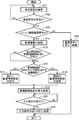
- FIG. 5 is a flowchart illustrating an operation related to notification of a detection result in the mobile terminal device of the monitored person monitoring system according to the embodiment.
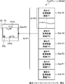
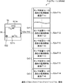
- FIG. 6 is a diagram for explaining a first storage mode of the display screen storage unit in the portable terminal device of the monitored person monitoring system according to the embodiment.
- FIG. 7 is a flowchart illustrating an operation related to deletion of the monitoring information screen in the monitored person monitoring system according to the embodiment.
- FIG. 7A shows an operation related to the deletion of the monitoring information screen in the management server device SV
- FIG. 7B shows an operation related to the deletion of the monitoring information screen in the mobile terminal device TA.
- FIG. 7A shows an operation related to the deletion of the monitoring information screen in the management server device SV
- FIG. 7B shows an operation related to the deletion of the monitoring information screen in the mobile terminal device TA.
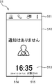
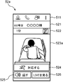
- FIG. 8 is a diagram illustrating an example of a standby screen displayed on the mobile terminal device in the monitored person monitoring system according to the embodiment.
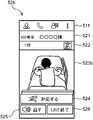
- FIG. 9 is a diagram illustrating an example of a monitoring information screen displaying a still image displayed on the mobile terminal device in the monitored person monitoring system according to the embodiment.
- FIG. 10 is a diagram illustrating an example of a monitoring information screen displaying a moving image displayed on the mobile terminal device in the monitored person monitoring system according to the embodiment.
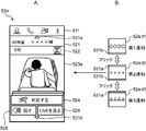
- FIG. 11 is a diagram illustrating an example of a monitoring information screen displayed on the mobile terminal device that has received a report from two or more different sensor devices.
- the mobile terminal device TA is activated when the power is turned on, accepts a login operation by a monitor (user) such as a nurse or a caregiver, and is automatically performed by the display processing unit 3221 of the TA monitoring processing unit 322.
- a standby screen for waiting for a communication signal addressed to the device is displayed on the TA display unit 36 (S11).
- the standby screen 51 includes a menu bar area 511 for displaying a menu bar, and a standby main area for displaying a message indicating standby (for example, “no notification”) and an icon.
- a time area 513 for displaying the current time a year / month / sunday area 514 for displaying the current year / month / sunday, and a user name area 515 for displaying the name of the user who is currently logged in to the portable terminal device TA.
- the portable terminal device TA determines whether or not the TA control unit 321 has received a communication signal addressed to itself by the TA communication IF unit 31 (S12). As a result of this determination, if the communication signal addressed to the own device is not received (No), the portable terminal device TA returns the process to S11, and as a result of the determination, receives the communication signal addressed to the own device. If yes (Yes), the portable terminal device TA executes the next process S13.
- the portable terminal device TA determines whether or not the received communication signal is an event notification communication signal by the TA monitoring processing unit 322. If the received communication signal is not an event notification communication signal as a result of this determination (No), the mobile terminal device TA uses the TA control processing unit 32 to perform appropriate processing (an example) according to the received communication signal. Then, each process shown in FIG. 7B described later is executed (S26), and this screen display operation is terminated. On the other hand, if the received communication signal is an event notification communication signal as a result of the determination (Yes), the mobile terminal device TA is accommodated in the received event notification communication signal by the TA monitoring processing unit 322.
- Sensor ID event type (type of action based on the detected action information (wake-up, get-off, fall, fall) in this embodiment), event time (or reception time), still image data (or file name) and video Is registered in the monitoring information table MT-TA so that they are associated with each other and stored in the TA monitoring information storage unit 332 (S14), and the next process S15 is executed.
- the TA monitoring processing unit 322 sets a default in the corresponding field 56-TA. To the registration of the flag "0".
- the mobile terminal device TA uses the TA monitoring processor 322 to monitor a monitored person Ob-A different from the monitored person Ob-B related to the monitoring information contained in the received event notification communication signal. It is determined whether another monitoring information screen 52-A (monitoring information screen 52a (52b)) for displaying information already exists, and the next process S16 is executed. Note that the determination result of the process S15 is used in each of a process S17, a process S18, and a process S19 described later. More specifically, the TA monitoring processing unit 322 has a sensor ID different from the sensor ID contained in the received event notification communication signal, and the sensor ID of the record in which the flag “0” is registered in the corresponding field 56-TA.
- the mobile terminal device TA monitors the sensor device SU in which the monitoring information contained in the received event notification communication signal is present on the monitoring information screen 52a (52b) by the TA monitoring processing unit 322. It is determined whether it is information. More specifically, the TA monitoring processor 322 sends an event report communication signal containing the same sensor ID as the sensor ID contained in the received event report communication signal before the received event report communication signal. It is determined whether or not the monitoring information screen 52a (52b) of the already received event notification communication signal has been created for display. More specifically, the TA monitoring processing unit 322 records the sensor ID field 51 of the record in which the same sensor ID as that contained in the received event notification communication signal registers the flag “0” in the corresponding field 56-TA.
- the received event notification communication signal When the same sensor ID as that stored in the sensor ID is registered in the sensor ID field 51-TA of the record in which the flag “0” is registered in the corresponding field 56-TA, an event notification communication signal of the same sensor ID is sent. It determines with having already received (Yes) and portable terminal device TA performs process S18.
- the mobile terminal device TA newly displays the monitoring information screen 52a according to each information (each data) contained in the received event notification communication signal by the display processing unit 3221 of the TA monitoring processing unit 322. Is formed and stored in the display screen storage unit 331.
- the monitoring information screen 52a is a screen for displaying the monitoring information related to monitoring of the monitored person Ob. As shown in FIG. 9, for example, the monitoring information screen 52a includes a menu bar area 511, the location of the sensor ID sensor device SU, and the monitored person Ob monitored by the sensor ID SU of the sensor ID.
- An image area 523a for displaying an image (here, a still image) captured by the ID sensor device SU, a “corresponding” button 524, a “speak” button 525, and a “view LIVE” button 526 are provided.
- the “corresponding” button 524 is an intention (responding intention, It is a button for inputting to the mobile terminal device TA that the user of the mobile terminal device TA has a handling intention and a willingness to respond.
- the “speak” button 525 is a button for requesting a voice call, and is used to input an instruction to connect the sensor device SU of the sensor ID and the mobile terminal device TA via the network NW. It is a button.
- the “LIVE” button 526 is a button for requesting a live video, and is a button for inputting an instruction to display a video captured by the sensor device SU of the sensor ID.
- the display processing unit 3221 corresponds to the sensor ID accommodated in the received event notification communication signal.
- the location and the name of the monitored person are searched from the TA sensor device information storage unit 333 using the sensor ID as a search key, and the elapsed time from the event time (or the reception time) contained in the received event notification communication signal Time is obtained, and an icon corresponding to the detection result represented by the detection behavior information contained in the received event notification communication signal is searched from the TA storage unit 33 using the detection result as a search key.
- each icon corresponding to each detection result (in this embodiment, getting up, getting out of bed, falling, and falling) is stored in advance in the TA storage unit 33 in association with each detection result.
- the display processing unit 3221 displays a menu bar in the menu bar area 511, displays the searched arrangement location and monitored person name in the monitored person name area 521, and calculates the obtained elapsed time and the searched item.
- An icon is displayed in the icon area 522, an image (still image) contained in the received event notification communication signal is displayed in the image area 523a, a “corresponding” button 524, a “speak” button 525, and “ By displaying a “LIVE” button 526, the monitoring information screen 52a is formed and stored in the display screen storage unit 331.
- the display processing unit 3221 determines that the monitoring information screen 52-A with a different sensor ID already exists as a result of the determination in the processing S15.
- the newly formed monitoring information screen 52a-B and the already existing monitoring information screen 52-A are associated with each other in the predetermined order and stored in the display screen storage unit 331. More specifically, the display processing unit 3221 displays the newly formed monitoring information screen 52a-B on the TA display unit 36 with respect to the already existing monitoring information screen 52-A. Are connected in chronological order to form a plane.
- the mobile terminal device TA displays a monitoring information screen according to each information (each data) accommodated in the received event notification communication signal by the display processing unit 3221 of the TA monitoring processing unit 322.
- 52a 52a-B is updated and formed and stored in the display screen storage unit 331.
- the display processing unit 3221 uses the event time (or reception) received in the received event notification communication signal. Elapsed time from (time) and search for an icon corresponding to the detection result represented by the detection behavior information contained in the received event notification communication signal from the TA storage unit 33 using the detection result as a search key. . Then, the display processing unit 3221 displays the obtained elapsed time and the searched icon in the icon area 522 on the existing monitoring information screen 52a-B, and is stored in the received event notification communication signal.
- the monitoring information screen 52a-B is updated by displaying the current image (still image) in the image area 523a and stored (formed) in the display screen storage unit 331.
- the searched icon is the icon that has already been displayed.
- the icon area 522 in time series. For example, when the determination result “getting up” is notified after the determination result “wake-up” of the monitored person Ob is notified, an icon representing the detection result “wake-up” of the monitored person Ob shown in FIG.
- the monitoring information screen 52a displayed in the area 522 is updated by displaying the icon representing the detection result “getting out” of the monitored person Ob next to the icon representing the detection result “getting up” in the icon area 522. Is done.
- the display processing unit 3221 When the monitoring information screen 52a-B is updated and formed in this way, the display processing unit 3221, as a result of the determination in the processing S15, already has the monitoring information screen 52-A of a different sensor ID as in the processing S17. If it exists, the updated monitoring information screen 52a-B and the existing monitoring information screen 52-A are associated with each other in the predetermined order and stored in the display screen storage unit 331. . More specifically, the display processing unit 3221 displays the updated monitoring information screen 52a-B on the TA display unit 36 with respect to the already existing monitoring information screen 52-A. Are connected in chronological order to form a plane. The display processing unit 3221 may maintain existing time-series associations (time-series connection) to associate them with the time series, and may display a new time series based on the received event notification communication signal. These may be associated and reorganized.
- the display processing unit 3221 executes a predetermined process for displaying the monitoring information screen 52a (S19). More specifically, the display processing unit 3221 determines that the monitoring information screen 52-A with a different sensor ID does not already exist as a result of the determination in the processing S15 (that is, one monitoring information by the processing S17 or the processing S18). When the screen 52a exists), the new monitoring information screen 52a newly created in the process S17 or the updated monitoring information screen 52a updated in the process S18 is displayed on the TA display unit 36.
- the display processing unit 3221 displays the monitoring information regarding each of a plurality of different monitored persons Ob when different monitoring information screens 52-A with different sensor IDs already exist as a result of the determination in the processing S15.
- the existing display contents displayed on the TA display unit 36 are maintained, and the new arrival monitoring information display 532 is further displayed on the existing display contents.
- FIG. 6 when a plurality of monitoring information screens 52-P1 exist, when a new event notification communication signal is received at time T0, the mobile terminal device TA performs processing S13, processing S14, processing S15, By executing the processing S16 and S17, the monitoring information screen 52a-T0 corresponding to the newly received event notification communication signal is formed, and the newly formed monitoring information screen 52a-T0 already exists.
- a plane PLa is formed by connecting the monitoring information screen 52 -P in time series in the vertical direction when displayed on the TA display unit 36 with respect to the monitoring information screen 52 -P, and is stored in the display screen storage unit 331.
- the plurality of monitoring information screens 52-P1 display the TAs of the monitoring information screens 52a-T4 related to the past time T4 with respect to the plurality of monitoring information screens 52-P0 including the monitoring information screens 52a-Tk related to the past time Tk.
- the monitor information screens 52a-T3 are displayed on the TA display unit 36, the monitor information screens 52a-T3 of the past time T3 are connected to the monitor information screens 52a-T4 in time series.
- the monitoring information screens 52a-T2 related to the past time T2 are connected to the monitoring information screens 52a-T3 in the time series in the vertical direction when displayed on the TA display unit 36, and
- the monitoring information screen 52a-T1 at the past time T1 is connected to the monitoring information screen 52a-T2 in time series in the vertical direction when the TA display unit 36 displays the plane. It is constructed by forming. Note that past ⁇ time Tk ⁇ ... ⁇ Time T4 ⁇ time T3 ⁇ time T2 ⁇ time T1 ⁇ time T0 ⁇ current time series.
- portable terminal device TA maintains the existing display content currently displayed on TA display part 36 by performing process S19, and also displays the new arrivals monitoring information display 532 on this existing display content. In the example shown in FIG.
- the monitoring information screens 52a-T4 for the past time T4 are displayed on the TA display unit 36, and in the process S19, the display of the monitoring information screens 52a-T4 is maintained.
- the new arrival monitoring information display 532 is further displayed on the screen 52a-T4.
- the portable terminal device TA determines whether or not an input operation is accepted by the TA control processing unit 32 using a touch panel including the TA input unit 35 and the TA display unit 36 (S20). If the input operation is not accepted as a result of this determination (No), the mobile terminal device TA returns the process to step S21. On the other hand, if the input operation is accepted as a result of the determination, the mobile terminal TA The apparatus TA performs the following process S21.
- the portable terminal device TA performs an appropriate process according to the content of the input operation by the TA control processing unit 32, and ends the screen display operation.
- the mobile terminal device TA accepts an input operation of the “watch live” button 526 by the TA control processing unit 32, the monitored person currently displayed on the TA display unit 36 by the TA streaming processing unit 324.
- a communication signal (moving image distribution request communication signal) containing information such as a request for live video distribution is transmitted to the sensor device SU that monitors Ob, and the sensor device SU and the network NW corresponding thereto are transmitted.
- the video is connected so that the video can be downloaded, the live video is distributed from the sensor device SU, and the video that has received the distribution is displayed on the TA display unit 36 by streaming reproduction. For example, as shown in FIG.
- the monitoring information screen 52 b that displays the live moving image is an image region 523 b that displays a moving image instead of the image region 523 a that displays a still image in the monitoring information screen 52 a illustrated in FIG. 9.
- a “LIVE END” button 528 is provided instead of the “VIEW LIVE” button 526.
- the “live end” button 528 is a button for requesting the end of the moving image, and is an instruction to end (stop) the distribution of the moving image captured by the sensor device SU of the sensor ID and end (stop) the display. It is a button for inputting.
- the mobile terminal device TA receives an input operation of the “live end” button 528 by the TA control processing unit 32, the monitored person currently displayed on the TA display unit 36 by the TA streaming processing unit 324.
- the TA display unit 36 displays a monitoring information screen 52a that displays a still image by transmitting a communication signal (moving image distribution end communication signal) containing information such as requesting the end of moving image distribution to the sensor device SU that monitors Ob. To display.
- a communication signal moving image distribution end communication signal
- the TA voice call processing unit 323 displays the monitored subject Ob displayed on the TA display unit 36.
- a communication signal (call request communication signal) containing information such as requesting a voice call is transmitted to the monitoring sensor device SU, and the corresponding sensor device SU is connected to the sensor device SU via the network NW so as to be able to make a voice call. .
- a voice call can be made between the mobile terminal device TA and the sensor device SU.
- a communication signal (call end communication signal) containing information such as a request to end the voice call is transmitted to the sensor device SU that monitors the monitored person Ob displayed on the TA display unit 36.
- the portable terminal device TA is currently displaying on the TA display unit 36.
- the flag “1” is registered in the corresponding field 56-TA.
- the monitoring information of the person Ob is not displayed on the TA display unit 36. More specifically, the display processing unit 3221 deletes the monitoring information screen 52a that displays the monitoring information of the monitored person Ob from the display screen storage unit 331, so that the monitoring information of the monitored person Ob is displayed as a TA. It is not displayed on the part 36.
- the display processing unit 3221 deletes the monitoring information screen 52a from the display screen storage unit 331, and displays the standby screen 51. The information is displayed on the TA display unit 36.
- the display processing unit 3221 deletes the monitoring information screen 52a from the display screen storage unit 331 and displays the remaining monitoring information screen 52a on the TA display unit 36.
- the display screen storage unit 331 is formed in a plane by connecting in time series in the vertical direction, and a predetermined monitoring information screen 52 a is displayed on the TA display unit 36.
- the monitoring information screen 52a that is closest in time to the deleted monitoring information screen 52a (the monitoring information screen 52a related to the event notification communication signal received immediately after forming the deleted monitoring information screen 52a, or the deleted monitoring information screen 52a)
- a monitoring information screen 52 a) related to the event notification communication signal received immediately before forming the information screen 52 a is displayed on the TA display unit 36.
- the monitoring information screen 52a related to the event notification communication signal received most recently in the remaining monitoring information screen 52a is displayed on the TA display unit 36.
- the monitoring information screen 52 a related to the event notification communication signal received most recently in the remaining monitoring information screen 52 a is displayed on the TA display unit 36.
- the display processing unit 3221 indicates that the monitor (user) logged in to the portable terminal device TA intends to execute the above-described response such as nursing on the monitored person Ob of the deleted monitoring information screen 52a (
- a communication signal for notifying that the response intention has been received is transmitted to the management server device SV.
- the correspondence notification communication signal information indicating that the intention to respond has been received (response intention reception information), sensor ID corresponding to the monitoring information on the deleted monitoring information screen 52a as information indicating the target of the correspondence, And the terminal ID of the said portable terminal device TA etc. are accommodated as information showing the main body which performs the said response
- the terminal ID is acquired from the TA storage unit 33.
- the mobile terminal device TA performs a “flick” input operation performed along a predetermined direction on the touch panel including the TA input unit 35 and the TA display unit 36 by the TA control processing unit 32.
- the display processing unit 3221 shifts to the display of the monitoring information screen 52 corresponding to the different monitoring information screen display 531 displayed at the flick source and displays it.
- the “flick” corresponds to an example of the switching instruction input.
- This separate monitoring information screen display 531 (531a, 531b) is a display indicating that the monitoring information screen 52a-B exists in addition to the monitoring information screen 52a-A displayed on the TA display unit 36.
- the monitoring being displayed is changed to the display of the monitoring information screen 52a-B corresponding to the separate monitoring information screen display 531 displayed at the flick source.
- the monitoring information screen 52a-B is displayed after shifting from the information screen 52a-A. More specifically, for example, as shown in FIG. 11, when a plurality of event notification communication signals are received and there are a plurality of monitoring information screens 52a corresponding to these signals, the display processing unit 3221 displays the first monitoring information.
- the first monitoring information screen 52a-t2 and the second monitoring information screen 52a-t1 are related in time series. If there is a third monitoring information screen 52a-t3 related to a time later than the first monitoring information screen 52a-t2, the first monitoring information screen 52a-t2 and the first monitoring information screen 52a-t2 3 monitoring information screens 52a-t3 are stored in the display screen storage unit 331 in a time-series manner.
- the display processing unit 3221 displays the first monitoring information screen 52a-t1 indicating the presence of the second monitoring information screen 52a-t1 when the first monitoring information screen 52a-t2 is displayed on the TA display unit 36.
- 531a is displayed at one end (upper end in the example shown in FIG. 11) on the first monitoring information screen 52a-t2, and a second separate monitoring information screen display 531b indicating the presence of the third monitoring information screen 52a-t3 is displayed. Is displayed on the other end (lower end in the example shown in FIG. 11) on the first monitoring information screen 52a-t2, and when an input operation of “flick” is accepted, another monitoring information screen displayed on the original flick is displayed.
- the monitor information screen 52a corresponding to 531 (531a, 531b) is shifted to display. More specifically, when a first flick performed along one direction from the bottom to the top of the touch panel is performed, the display processing unit 3221 displays the first monitoring information screen 52a- displayed on the TA display unit 36.
- the display processing unit 3221 displays the first monitoring information screen 52a-t2 displayed on the TA display unit 36 from the newest to the oldest.
- the display is switched to the second monitoring information screen 52a-t1 and displayed on the TA display unit 36.
- the plurality of monitoring information screens 52a are related to each other in time series and stored in the display screen storage unit 331, a plurality of detection results are moved from the oldest to the newer by a so-called flick operation.
- the TA display unit 36 can sequentially display in the forward direction or the reverse direction from the newer to the older.
- the past monitoring information screen 52a-T4 including the new arrival monitoring information display 532 is displayed on the TA display unit 36 of the portable terminal device TA, this new arrival monitoring is performed.
- a first flick is performed on the touch panel along one direction from the bottom to the top.
- the past monitoring information screen 52a-T4 the past monitoring information screen 52a-T3, the past monitoring information screen 52a-T2, and the past monitoring information screen 52a-T1 are respectively displayed.
- the latest monitoring information screen 52a-T0 is displayed on the TA display 36, and the new arrival monitoring information display 532 is erased from the TA display 36. Is done. In this way, a plurality of monitoring information screens 52a-T3 to 52 relating to a plurality of event notification communication signals already received between the previously displayed past monitoring information screens 52a-T4 and the latest monitoring information screens 52a-T0. After displaying all 52a-T1, the latest monitoring information screen 52a-T0 of the newly received event notification communication signal is displayed on the TA display unit 36.
- the management server device SV when the management server device SV receives a communication signal addressed to itself by the SV communication IF unit 21 by the SV control unit 221 (S31), the SV monitoring processing unit 222 receives the received communication signal. Is determined (S32). As a result of this determination, when the received communication signal is a correspondence notification communication signal (correspondence notification), the management server device SV executes processing S33, and when the received communication signal is not a correspondence notification communication signal ( For others, the process S34 is executed.
- the management server device SV uses the SV monitoring processing unit 222 to record the correspondence field 56- in the record in which the sensor ID accommodated in the received correspondence notification communication signal is registered in the sensor ID field 51-SV.
- the flag “1” is registered in the SV, and a correspondence unnecessary notification communication signal which is a communication signal for not displaying the monitoring information of the monitored person Ob who has accepted the response intention by the response notification communication signal received in the processing S31 is SV communication.
- the broadcast is transmitted via the IF unit 21 and the screen display erasing operation is terminated.
- the sensor ID accommodated in the correspondence notification communication signal received in the process S31 and the sensor device corresponding to the sensor ID are included in the correspondence unnecessary notification communication signal.
- Information (command, monitoring information screen deletion instruction information, monitoring information screen deletion command) indicating that the monitoring information screen 52a (52b) related to SU is instructed to be deleted (command, command), and the monitoring information screen deletion communication signal Is received in response field 56-SV in terminal device SP, TA that has received the message, response intention acceptance information and the like are stored.
- the management server apparatus SV performs an appropriate process according to the received communication signal by the SV control processing unit 22, and ends this screen display erasing operation.
- the mobile terminal device TA that has received the notification signal indicating that no response is required operates as follows.
- the portable terminal device TA determines the type of the received communication signal by the TA monitoring processing unit 322 (S41). As a result of this determination, when the received communication signal is a correspondence unnecessary notification communication signal (corresponding unnecessary), the portable terminal device TA executes the process S42, and the received communication signal is not a correspondence unnecessary notification communication signal. In the case (others), the process S43 is executed.
- the mobile terminal device TA first has a monitoring information screen 52a (52b) related to the sensor device SU of the sensor ID accommodated in the received correspondence unnecessary notification communication signal by the TA monitoring processor 322. It is determined whether or not to do. If the monitoring information screen 52a (52b) does not exist as a result of this determination, the TA monitoring processing unit 322 ends this screen display erasing operation. On the other hand, if the monitoring information screen 52a (52b) exists as a result of the determination, the TA monitoring processing unit 322 uses the sensor ID field 51-TA to store the sensor ID accommodated in the received correspondence unnecessary notification communication signal.
- the flag “1” is registered in the correspondence field 56-TA in the record registered in “1”, and monitoring information of the monitored person Ob related to the received correspondence unnecessary notification communication signal is not displayed on the TA display unit 36.
- the display processing unit 3221 is related to the sensor device SU of the sensor ID accommodated in the received correspondence unnecessary notification communication signal, similarly to the case where the input operation of the “corresponding” button 524 is received.
- the monitoring information screen 52a (52b) from the display screen storage unit 331 of the TA storage unit 33, the monitoring information of the monitored person Ob is not displayed on the TA display unit 36.
- the display screen storage unit 331 stores a plurality of monitoring information screens 52a, it is formed before and after the deleted monitoring information screen 52a (52b) by deleting the monitoring information screen 52a (52b).
- the monitoring information screen 52a being connected is linked.
- the monitoring information screen 52a (52b) that has received the “corresponding” button 524 is erased in each mobile terminal device TA, and the monitoring information of the monitored subject Ob associated with this correspondence unnecessary notification communication signal is displayed in the TA display unit 36. Is not displayed.
- the display processing unit 3221 ends the screen display erasing operation.
- the portable terminal device TA performs an appropriate process according to the received communication signal by the TA control processing unit 32, and ends this screen display erasing operation.
- the terminal devices SP and TA which are examples of the display device, and the method implemented therein, the sensor device SU performs a predetermined action on the monitored person Ob. Is detected, a notification of the detection result is newly received from the sensor device SU via the management server device SV which is an example of the central processing unit, for example, by the mobile terminal device TA.
- the display processing unit 3221 maintains the existing display content displayed on the TA display unit 36, and uses the newly received monitoring information display 532 as an example of a code representing the presence of the newly received detection result.
- the newly received detection result is displayed on the TA display unit 36. Therefore, since the existing display content is preferentially displayed on the TA display unit 36 with respect to the newly received detection result, the monitored person monitoring system MS, the terminal device SP, TA, and the method described above are not notified. It is possible to urge the patient (correspondence, response) more reliably. Further, even if the existing display contents are maintained in this way, the new arrival monitoring information display 532 indicating the presence of the newly received detection result is further displayed on the TA display unit 36. The user can recognize the presence of the newly received detection result.
- the predetermined condition in the monitored person Ob is used. Is detected and reported, and its display is executed.
- the terminal devices SP, TA and the method for example, when the corresponding intention is received by an input operation of the “corresponding” button 524 from the TA input unit 35, the display processing unit 3221 is described above. Therefore, it is possible to prevent the TA display unit 36 from displaying the detection result of the monitored person Ob who has accepted the response intention and does not need to be displayed due to the achievement of the object.
- the correspondence notification communication signal is transmitted and the correspondence unnecessary notification communication signal is received. Therefore, at least one of the plurality of portable terminal devices TA
- the response intention is received from the TA input unit 35 by the input operation of the “corresponding” button 524
- the response intention that does not need to be displayed due to the achievement of the object is received by all the terminal devices SP and TA.
- the detection result of the monitored person Ob can be prevented from being displayed on the TA display unit 36, and the plurality of terminal devices SP and TA can be linked (synchronized) with respect to the non-display of the detection result.
- the terminal devices SP and TA when there are a plurality of unsupported monitoring information screens 52a that receive a plurality of event notification communication signals and do not accept the intention to respond, the terminal devices SP and TA are displayed.
- the total number (total number) of the plurality of monitoring information screens 52a including the monitoring information screen 52a or the total number (standby number) of the plurality of monitoring information screens 52a excluding the currently displayed monitoring information screen 52a is displayed. May be.
- the mobile terminal device TA uses the display processing unit 3221 to monitor the number of standbys on the monitoring information screen 52a connected to the first monitoring information screen display 531a with respect to the monitoring information screen 52a being displayed.
- the information is displayed on the TA display unit 36 in proximity to the 2-by-2 monitoring information screen display 531b.
- the display processing unit 3221 displays the number of standby cases “4” on the TA display unit 36 in proximity to the second separate monitoring information screen display 531 b.
- the sensor device SU (sensor ID) and the monitoring information screen 52a have a one-to-one correspondence, and monitoring according to an event notification communication signal notified from the same sensor device SU (sensor ID).
- the information screen 52a is updated by the reception of the event notification communication signal.
- the monitoring information screen 52a is created every time the event notification communication signal is received, and is formed into a plane in time series. , And may be stored in the display screen storage unit 331. In this case, the process S16 and the process S18 described above are omitted, and the process S19 is executed via the process S16 to the process S17.
- FIG. 12 is a diagram for explaining a second storage mode of the display screen storage unit in the portable terminal device of the monitored person monitoring system according to the embodiment.
- FIG. 13 is a diagram for explaining a third storage mode of the display screen storage unit in the portable terminal device of the monitored person monitoring system according to the embodiment.
- the plurality of monitoring information screens 52a are simply connected in chronological order in the order of event time (or in order of reception time) to form a plane, stored in the display screen storage unit 331, and stored in the TA input unit 35.
- the received switching instruction (“flick” in the above example)
- it may be displayed on the TA display unit 36 in chronological order, but the plane formation method and the display method are limited to this. Instead, it can be modified appropriately.
- the display processing unit 3221 when the display processing unit 3221 receives a report of monitoring information from each of the plurality of sensor devices SU via the management server device SV by an event notification communication signal, the plurality of pieces of monitoring information A plurality of monitoring information screens 52a based on each are grouped for each sensor device SU based on the sensor ID, the plurality of monitoring information screens 52a are connected for each group Gr, and each group Gr is further connected to form a plane PLb.
- the switching instruction "flick" in the above example
- the TA input unit 35 it is displayed on the TA display unit 36 sequentially for each group Gr. good.
- the plurality of monitoring information screens 52a are connected in time series. According to this, since a plurality of monitoring information is sequentially displayed on the TA display unit 36 for each sensor device SU, the monitoring information can be referred to for each monitored person Ob monitored by the sensor device SU.
- the plane PLb that includes a plurality of monitoring information screens 52a-T1k,..., 52a-T14 to 52a-T10 and is stored in the display screen storage unit 331 is the first sensor device SU.
- -1 includes a plurality of monitoring information screens 52a-T1k,..., 52a-T12, 52a-T10 related to a plurality of event notification communication signals notified from the management server device SV from -1.
- a second group comprising a plurality of monitoring information screens 52a-T13, 52a-T11 relating to a plurality of event notification communication signals notified from the second sensor device SU-2 via the management server device SV Gr2 and the monitoring information screen 52a-T1 related to the event notification communication signal notified from the third sensor device SU-3 via the management server device SV
- a third group Gr3 configured with a (for example, a sensor device preassigned numerical order SU, etc.).
- the monitoring information screens 52a are connected to each other in time series. Note that past ⁇ time T1k ⁇ ...
- the display processing unit 3221 displays the latest monitoring information screen 52a-T10 related to the newly received event notification communication signal in the first group Gr1.
- 52a-T12 are connected to the existing monitoring information screens 52a-T1k,..., 52a-T12 in time series to form a plane PLb, which is stored in the display screen storage unit 331 and stored in the existing display.
- the display of the monitoring information screen 52a-T12 is maintained, and the new arrival monitoring information display 532 is further displayed on the monitoring information screen 52a-T12.
- the display processing unit 3221 when the display processing unit 3221 receives a plurality of monitoring information notifications by a plurality of event notification communication signals via the management server device SV, the display processing unit 3221 A plurality of monitoring information screens 52a based on the group are grouped according to the importance set in advance according to the predetermined action type, and the plurality of monitoring information screens 52a are linked for each group Gr, and each group Gr is further linked Then, a plane PLb is formed, stored in the display screen storage unit 331, and sequentially displayed for each group Gr according to the switching instruction ("flick" in the above example) received by the TA input unit 35. May be displayed.
- the plurality of monitoring information screens 52a are connected in time series.
- the importance is an index representing the importance of the monitoring information, and is set in advance according to the predetermined action type as described above.
- the correspondence relationship between the action type and the importance value is stored in advance in the SV storage unit 23 of the management server device SV, and is transmitted from the management server device SV to the mobile terminal device TA at the time of login. It is stored in the TA storage unit 33 of the portable terminal device TA.
- the most important importance level 1 is set for each fall and fall
- the importance level 2 is set after the importance level 1 for getting out of the floor
- the importance level 2 is set for getting up.
- it is configured by setting important importance level 3 (most important; importance level 1> importance level 2> importance level 3). According to this, since a plurality of monitoring information is sequentially displayed on the TA display unit 36 for each importance, the monitoring information can be referred to for each importance.
- the plane PLc that includes a plurality of monitoring information screens 52a-T2k,..., 52a-T24 to 52a-T20 and is stored in the display screen storage unit 331 is managed from the sensor device SU.
- a first group comprising a plurality of monitoring information screens 52a-T2k,..., 52a-T22, 52a-T20 of importance 1 relating to a plurality of event notification communication signals notified via the server device SV Gr11 and a second group including a plurality of monitoring information screens 52a-T23, 52a-T21 of importance 2 related to a plurality of event notification communication signals notified from the sensor device SU via the management server device SV Gr12 and the monitoring information screen 5 of importance 3 related to the event notification communication signal notified from the sensor device SU via the management server device SV Coupled with the each other and a third group Gr13 configured with the a-T24 predetermined rank (for example, in order of severity, etc.) are formed.
- the monitoring information screens 52a are connected to each other in time series. Note that past ⁇ time T2k ⁇ ... ⁇ Time T24 ⁇ time T23 ⁇ time T22 ⁇ time T21 ⁇ time T20 ⁇ current time series.
- the display processing unit 3221 newly receives a notification of the event notification communication signal via the TA communication IF unit 31, the display processing unit 3221 maintains the existing display content displayed on the TA display unit 36, and this existing display.
- the new arrival monitoring information display 532 is further displayed in the contents. In the example shown in FIG.
- the event notification communication is performed from the sensor device SU via the management server device SV.
- the display processing unit 3221 displays the latest monitoring information screen 52a-T20 having the importance level 1 relating to the newly received event report communication signal within the first group Gr11.
- the existing monitoring information screens 52a-T2k,..., 52a-T22 are connected to the existing monitoring information screens 52a-T2k,..., 52a-T22 in time series to form a plane PLc, which is stored in the display screen storage unit 331, and is displayed on the existing monitoring information screens 52a-T22.
- the new arrival monitoring information display 532 is further displayed on the monitoring information screen 52a-T22.
- these groupings may be mixed.
- the plurality of monitoring information screens 52a are first grouped by sensor device SU, and then grouped by importance in each of these groups. Further, for example, the plurality of monitoring information screens 52a are first grouped by importance, and then grouped by sensor device SU in each of these groups.
- the display device is connected to be able to communicate with a sensor device that detects and reports a predetermined action in a monitored person, a display device that displays predetermined information, and the sensor device and the display device,
- a display device of a monitored person monitoring system comprising: a central processing unit that receives a notification of a detection result detected by the sensor device from the sensor device and reports the detection result to the display device, and performs communication
- a display unit for displaying, an input unit for receiving a switching instruction input for switching display contents displayed on the display unit, and the detection result notified from the central processing unit are displayed on the display unit A display processing unit, and when the display processing unit newly receives a notification of the detection result via the communication unit, the display processing unit And a sign indicating the presence of the newly received detection result is further displayed on the display unit, and when the switching instruction input is received by the input unit, the newly received detection result is Display on the display.
- the display processing unit when the display processing unit newly receives the detection result report via the communication unit, the display processing unit maintains the existing display content displayed on the display unit, and A code representing the presence of the newly received detection result is further displayed on the display unit, and when the switching instruction input is received by the input unit, the detection result newly received from the existing display content is displayed. After displaying all the detection results in between, the newly received detection results are displayed on the display unit.
- Such a display device newly receives a notification of a detection result from the sensor device via the central processing unit when the sensor device detects a predetermined action of the monitored person.
- the display processing unit maintains the existing display contents displayed on the display unit, further displays a code indicating the presence of the newly received detection result on the display unit, and switches at the input unit.
- the newly received detection result is displayed on the display unit. Therefore, since the existing display content is preferentially displayed on the display unit with respect to the newly received detection result, the display device more reliably prompts the patient to respond to the already-notified notification. be able to.
- a code representing the presence of the newly received detection result is further displayed on the display unit. The presence of the received detection result can be recognized.
- the input unit further receives a response intention input of a monitor indicating that the monitor person has an intention to actually respond
- the display processing unit includes: When the response intention input is received by the input unit, the detection result of the monitored person who has received the response intention is not displayed on the display unit.
- the monitored person monitoring system when a predetermined situation occurs in the monitored person, a predetermined action in the monitored person is detected for the purpose of encouraging the monitoring person to respond to the monitored person. Is reported and the display is executed.
- the display device when a response intention input is received by the input unit, the detection result of the monitored person who has received the response intention input and does not need to be displayed due to the achievement of the purpose can be prevented from being displayed on the display unit. .
- the input unit further accepts a response intention input indicating that there is an intention to actually respond to the monitored person
- the display processing unit is the input unit.
- a response notification communication signal for notifying the monitored person that the response intention input has been received is transmitted from the communication unit to the central processing unit, and the response intention is received. If a response notification notification signal for preventing the display of the detection result of the monitored person is received, the detection result of the monitored person related to the received notification message of the unnecessary response is not displayed on the display unit.
- Such a display device transmits a correspondence notification communication signal and receives a correspondence unnecessary notification communication signal, when a correspondence intention input is received at at least one of the plurality of display devices, the plurality of displays
- the detection result of the monitored person who has received the response intention input that does not need to be displayed due to the achievement of the object can be prevented from being displayed on the display unit. Can be linked (synchronized).
- the display unit and the input unit constitute a touch panel
- the switching instruction input is performed in one direction with respect to the touch panel in the first flick and the touch panel.
- the second flick is performed along the other direction (the other direction opposite to the one direction) that is opposite to the one direction, and the display processing unit performs the first flick on the touch panel.
- the detection result displayed on the display unit is switched in the forward direction from the oldest to the newer and displayed on the display unit.
- the detection result displayed on the display unit is switched in the reverse direction from the newer to the older and displayed on the display.
- Such a display device can sequentially display a plurality of detection results on the display unit in the forward direction from the older to the newer or in the reverse direction from the newer to the older by so-called flick operation.
- the display processing unit receives the detection result notification from each of the plurality of sensor devices via the central processing unit, and the plurality of detection results are received for each sensor device. And the plurality of detection results are sequentially displayed on the display unit for each group.
- the detection results can be referred to for each monitored person monitored by the sensor device.
- the display processing unit receives a plurality of detection result reports via the central processing unit, and converts the plurality of detection results into the predetermined action type. In response to this, grouping is performed for each importance level set in advance, and the plurality of detection results are sequentially displayed on the display unit for each group.
- a display method includes a sensor device that detects and reports a predetermined action in a monitored person, a display device that displays predetermined information, and a communication device that is communicably connected to the sensor device and the display device. And a central processing unit that receives a notification of a detection result detected by the sensor device from the sensor device and reports the detection result to the display device.
- a communication process for performing communication a display process for displaying on the display section, an input process for accepting a switching instruction input for switching display contents displayed on the display section at the input section, and a notification from the central processing unit.
- the existing display content displayed on the display unit is maintained, the code representing the presence of the newly received detection result is further displayed on the display unit, and the switching instruction input is received by the input unit
- the newly received detection result is displayed on the display unit.
- a notification of a detection result is newly received from the sensor device via the central processing unit.
- the display processing step maintains the existing display contents displayed on the display unit, further displays a code representing the presence of the newly received detection result on the display unit, and switches at the input unit.
- the newly received detection result is displayed on the display unit. Therefore, since the existing display content is preferentially displayed on the display unit with respect to the newly received detection result, the above display method more surely prompts the patient (or the like) for the already notified notification. be able to.
- a code representing the presence of the newly received detection result is further displayed on the display unit. The presence of the received detection result can be recognized.
- a monitored person monitoring system includes a sensor device that detects and notifies a predetermined action of a monitored person, a display device that displays predetermined information, and the sensor device and the display device.
- a monitoring target monitoring system comprising a central processing unit connected to the display device and receiving a notification of a detection result detected by the sensor device from the sensor device and reporting the detection result to the display device.
- the device is any of these display devices.
- Such a monitored person monitoring system includes any one of the above-described display devices, it is possible to more surely promote a response (response, response) to a patient or the like related to the notification.
- a display device and a display method of a monitored person monitoring system and a monitored person monitoring system can be provided.
Landscapes
- Health & Medical Sciences (AREA)
- Business, Economics & Management (AREA)
- Engineering & Computer Science (AREA)
- General Physics & Mathematics (AREA)
- Physics & Mathematics (AREA)
- Emergency Management (AREA)
- General Health & Medical Sciences (AREA)
- Gerontology & Geriatric Medicine (AREA)
- Multimedia (AREA)
- Public Health (AREA)
- Biomedical Technology (AREA)
- General Engineering & Computer Science (AREA)
- Theoretical Computer Science (AREA)
- Animal Behavior & Ethology (AREA)
- Signal Processing (AREA)
- Veterinary Medicine (AREA)
- Nursing (AREA)
- Life Sciences & Earth Sciences (AREA)
- Psychology (AREA)
- Medical Informatics (AREA)
- General Business, Economics & Management (AREA)
- Psychiatry (AREA)
- Primary Health Care (AREA)
- Social Psychology (AREA)
- Epidemiology (AREA)
- Human Computer Interaction (AREA)
- Alarm Systems (AREA)
- Telephonic Communication Services (AREA)
- Emergency Alarm Devices (AREA)
- Accommodation For Nursing Or Treatment Tables (AREA)
- Telephone Function (AREA)
- Measuring And Recording Apparatus For Diagnosis (AREA)
- Interconnected Communication Systems, Intercoms, And Interphones (AREA)
Abstract
Description
Claims (8)
- 被監視者における所定の行動を検知して通報するセンサ装置と、所定の情報を表示する表示装置と、前記センサ装置および前記表示装置それぞれと通信可能に接続され、前記センサ装置で検知した検知結果の通報を前記センサ装置から受信して前記表示装置へ前記検知結果を通報する中央処理装置とを備える被監視者監視システムの前記表示装置であって、
通信を行う通信部と、
表示を行う表示部と、
前記表示部に表示されている表示内容を切り換える切換指示入力を受け付ける入力部と、
前記中央処理装置から通報された前記検知結果を前記表示部に表示する表示処理部とを備え、
前記表示処理部は、前記通信部を介して前記検知結果の通報を新たに受信した場合、前記表示部に表示されている既存の表示内容を維持し、前記新たに受信した前記検知結果の存在を表す符号を前記表示部にさらに表示し、前記入力部で前記切換指示入力を受け付けた場合に、前記新たに受信した前記検知結果を前記表示部に表示する、
表示装置。 - 前記入力部は、前記被監視者に対し実際に対応する意思がある旨を示す監視者の対応意思入力をさらに受け付け、
前記表示処理部は、前記入力部で前記対応意思入力を受け付けた場合に、前記対応意思を受け付けた被監視者の検知結果を前記表示部に表示しない、
請求項1に記載の表示装置。 - 前記入力部は、前記被監視者に対し実際に対応する意思がある旨の対応意思入力をさらに受け付け、
前記表示処理部は、前記入力部で前記対応意思入力を受け付けた場合に、前記被監視者に対し前記対応意思入力を受け付けた旨を通知するための対応通知通信信号を前記通信部から前記中央処理装置へ送信し、対応意思を受け付けた被監視者の検知結果を表示させないための対応不要通知通信信号を受信した場合に、前記受信した対応不要通知通信信号にかかる被監視者の検知結果を前記表示部に表示しない、
請求項1または請求項2に記載の表示装置。 - 前記表示部および前記入力部は、タッチパネルを構成し、
前記切換指示入力は、前記タッチパネルに対し一方方向に沿って行われる第1フリックおよび前記タッチパネルに対し前記一方方向の逆方向である他方方向に沿って行われる第2フリックであり、
前記表示処理部は、前記タッチパネルに対し前記第1フリックが行われた場合に、前記表示部に表示される前記検知結果を古い方から新しい方へ向かう順方向で切り換えて前記表示部に表示し、前記タッチパネルに対し前記第2フリックが行われた場合に、前記表示部に表示される前記検知結果を前記新しい方から前記古い方へ向かう逆方向で切り換えて前記表示部に表示する、
請求項1ないし請求項3のいずれか1項に記載の表示装置。 - 前記表示処理部は、前記中央処理装置を介して複数のセンサ装置それぞれから前記検知結果の通報を受信し、前記複数の検知結果をセンサ装置ごとにグループ化し、前記複数の検知結果をグループごとに順次に前記表示部に表示する、
請求項1ないし請求項4のいずれか1項に記載の表示装置。 - 前記表示処理部は、前記中央処理装置を介して複数の検知結果の通報を受信し、前記複数の検知結果を、前記所定の行動の種別に応じて予め設定された重要度ごとにグループ化し、前記複数の検知結果をグループごとに順次に前記表示部に表示する、
請求項1ないし請求項5のいずれか1項に記載の表示装置。 - 被監視者における所定の行動を検知して通報するセンサ装置と、所定の情報を表示する表示装置と、前記センサ装置および前記表示装置それぞれと通信可能に接続され、前記センサ装置で検知した検知結果の通報を前記センサ装置から受信して前記表示装置へ前記検知結果を通報する中央処理装置とを備える被監視者監視システムの表示方法であって、
通信部で通信を行う通信工程と、
表示部に表示を行う表示工程と、
前記表示部に表示されている表示内容を切り換える切換指示入力を入力部で受け付ける入力工程と、
前記中央処理装置から通報された前記検知結果を前記表示部に表示する表示処理工程とを備え、
前記表示処理工程は、前記通信部を介して前記検知結果の通報を新たに受信した場合、前記表示部に表示されている既存の表示内容を維持し、前記新たに受信した前記検知結果の存在を表す符号を前記表示部にさらに表示し、前記入力部で前記切換指示入力を受け付けた場合に、前記新たに受信した前記検知結果を前記表示部に表示する、
表示方法。 - 被監視者における所定の行動を検知して通報するセンサ装置と、所定の情報を表示する表示装置と、前記センサ装置および前記表示装置それぞれと通信可能に接続され、前記センサ装置で検知した検知結果の通報を前記センサ装置から受信して前記表示装置へ前記検知結果を通報する中央処理装置とを備える被監視者監視システムであって、
前記表示装置は、請求項1ないし請求項6のいずれか1項に記載の表示装置である、
被監視者監視システム。
Priority Applications (5)
| Application Number | Priority Date | Filing Date | Title |
|---|---|---|---|
| US15/751,286 US10276012B2 (en) | 2015-08-10 | 2016-07-27 | Display device and display method for system for monitoring person to be monitored, and system for monitoring person to be monitored |
| CN201680045807.4A CN107924605A (zh) | 2015-08-10 | 2016-07-27 | 被监视者监视系统的显示装置以及显示方法及被监视者监视系统 |
| JP2017506433A JP6150028B1 (ja) | 2015-08-10 | 2016-07-27 | 被監視者監視システムの表示装置および表示方法ならびに被監視者監視システム |
| EP16834980.1A EP3330937A4 (en) | 2015-08-10 | 2016-07-27 | Display device and display method for system for monitoring person to be monitored, and system for monitoring person to be monitored |
| US16/298,206 US20190206217A1 (en) | 2015-08-10 | 2019-03-11 | Display device and display method for system for monitoring person to be monitored, and system for monitoring person to be monitored |
Applications Claiming Priority (2)
| Application Number | Priority Date | Filing Date | Title |
|---|---|---|---|
| JP2015-158154 | 2015-08-10 | ||
| JP2015158154 | 2015-08-10 |
Related Child Applications (2)
| Application Number | Title | Priority Date | Filing Date |
|---|---|---|---|
| US15/751,286 A-371-Of-International US10276012B2 (en) | 2015-08-10 | 2016-07-27 | Display device and display method for system for monitoring person to be monitored, and system for monitoring person to be monitored |
| US16/298,206 Division US20190206217A1 (en) | 2015-08-10 | 2019-03-11 | Display device and display method for system for monitoring person to be monitored, and system for monitoring person to be monitored |
Publications (1)
| Publication Number | Publication Date |
|---|---|
| WO2017026283A1 true WO2017026283A1 (ja) | 2017-02-16 |
Family
ID=57983218
Family Applications (1)
| Application Number | Title | Priority Date | Filing Date |
|---|---|---|---|
| PCT/JP2016/072000 WO2017026283A1 (ja) | 2015-08-10 | 2016-07-27 | 被監視者監視システムの表示装置および表示方法ならびに被監視者監視システム |
Country Status (5)
| Country | Link |
|---|---|
| US (2) | US10276012B2 (ja) |
| EP (1) | EP3330937A4 (ja) |
| JP (3) | JP6150028B1 (ja) |
| CN (1) | CN107924605A (ja) |
| WO (1) | WO2017026283A1 (ja) |
Cited By (1)
| Publication number | Priority date | Publication date | Assignee | Title |
|---|---|---|---|---|
| WO2019155775A1 (ja) * | 2018-02-09 | 2019-08-15 | コニカミノルタ株式会社 | 見守りシステム、およびイベントリストの表示方法 |
Families Citing this family (5)
| Publication number | Priority date | Publication date | Assignee | Title |
|---|---|---|---|---|
| US9361011B1 (en) * | 2015-06-14 | 2016-06-07 | Google Inc. | Methods and systems for presenting multiple live video feeds in a user interface |
| JP7031585B2 (ja) * | 2016-06-29 | 2022-03-08 | コニカミノルタ株式会社 | 看介護記録システムの中央処理装置、プログラムおよび看介護記録システム |
| GB2556926A (en) * | 2016-11-25 | 2018-06-13 | Metrasens Ltd | Monitoring system for a detection system |
| JP6635074B2 (ja) * | 2017-03-02 | 2020-01-22 | オムロン株式会社 | 見守り支援システム及びその制御方法 |
| JP6819423B2 (ja) * | 2017-04-04 | 2021-01-27 | 富士ゼロックス株式会社 | 無線通信装置 |
Citations (6)
| Publication number | Priority date | Publication date | Assignee | Title |
|---|---|---|---|---|
| JPS6326798A (ja) * | 1986-07-21 | 1988-02-04 | 株式会社日立製作所 | プロセス警報表示装置 |
| JP2004334763A (ja) * | 2003-05-12 | 2004-11-25 | Matsushita Electric Ind Co Ltd | 通報表示装置 |
| JP2013120569A (ja) * | 2011-12-08 | 2013-06-17 | Sharp Corp | 表示装置、情報端末装置、表示方法、プログラム、および記録媒体 |
| JP2014090913A (ja) * | 2012-11-05 | 2014-05-19 | Aiphone Co Ltd | ナースコールシステム及び状態判断システム |
| JP2014204752A (ja) * | 2013-04-10 | 2014-10-30 | Necプラットフォームズ株式会社 | ナースコールシステム、ナースコール制御方法およびナースコール制御プログラム |
| JP2015058030A (ja) * | 2013-09-17 | 2015-03-30 | 東芝情報システム株式会社 | 見守りシステム |
Family Cites Families (17)
| Publication number | Priority date | Publication date | Assignee | Title |
|---|---|---|---|---|
| US5699038A (en) * | 1993-07-12 | 1997-12-16 | Hill-Rom, Inc. | Bed status information system for hospital beds |
| US20040167804A1 (en) * | 2002-04-30 | 2004-08-26 | Simpson Thomas L.C. | Medical data communication notification and messaging system and method |
| JP2004173194A (ja) * | 2002-11-22 | 2004-06-17 | Fujitsu Ltd | ナースコールシステム |
| US7541935B2 (en) * | 2005-05-19 | 2009-06-02 | Proacticare Llc | System and methods for monitoring caregiver performance |
| US7671733B2 (en) * | 2006-03-17 | 2010-03-02 | Koninklijke Philips Electronics N.V. | Method and system for medical alarm monitoring, reporting and normalization |
| JP4468327B2 (ja) * | 2006-05-12 | 2010-05-26 | 株式会社日立製作所 | コールセンタシステムにおけるスーパバイザ業務支援方法 |
| US11253159B2 (en) * | 2010-01-31 | 2022-02-22 | Vladimir Shusterman | Tracking cardiac forces and arterial blood pressure using accelerometers |
| JP5535725B2 (ja) * | 2010-03-31 | 2014-07-02 | 富士フイルム株式会社 | 内視鏡観察支援システム、並びに、内視鏡観察支援装置、その作動方法およびプログラム |
| CN102103786A (zh) * | 2011-03-03 | 2011-06-22 | 南昌大学 | 一种基于无线通讯技术追踪监护的系统和方法 |
| US9501919B2 (en) * | 2011-03-11 | 2016-11-22 | Elisabeth Laett | Method and system for monitoring the activity of a subject within spatial temporal and/or behavioral parameters |
| US20130267873A1 (en) * | 2012-04-10 | 2013-10-10 | Mindray Ds Usa, Inc. | Systems and methods for monitoring patients with real-time video |
| US9233038B2 (en) * | 2012-09-04 | 2016-01-12 | Hill-Rom Services, Inc. | Patient support with a microclimate system and a graphical user interface |
| JP6182917B2 (ja) * | 2013-03-15 | 2017-08-23 | ノーリツプレシジョン株式会社 | 監視装置 |
| US20140322815A1 (en) * | 2013-04-26 | 2014-10-30 | Roche Diagnostics Operations, Inc. | Pairing and synchronizing a mobile phone application with a handheld glucose meter |
| JP2015106289A (ja) * | 2013-11-29 | 2015-06-08 | キヤノン株式会社 | 表示装置、表示方法、コンピュータプログラム |
| CN104504852A (zh) * | 2014-10-24 | 2015-04-08 | 天津科技大学 | 一种基于图像预警婴儿安全监护器及婴儿安全判断方法 |
| JP2016103237A (ja) * | 2014-11-28 | 2016-06-02 | クラリオン株式会社 | 見守りシステム |
-
2016
- 2016-07-27 US US15/751,286 patent/US10276012B2/en not_active Expired - Fee Related
- 2016-07-27 CN CN201680045807.4A patent/CN107924605A/zh active Pending
- 2016-07-27 WO PCT/JP2016/072000 patent/WO2017026283A1/ja active Application Filing
- 2016-07-27 EP EP16834980.1A patent/EP3330937A4/en not_active Withdrawn
- 2016-07-27 JP JP2017506433A patent/JP6150028B1/ja active Active
-
2017
- 2017-05-24 JP JP2017102534A patent/JP6443493B2/ja active Active
-
2018
- 2018-11-28 JP JP2018221915A patent/JP6721027B2/ja active Active
-
2019
- 2019-03-11 US US16/298,206 patent/US20190206217A1/en not_active Abandoned
Patent Citations (6)
| Publication number | Priority date | Publication date | Assignee | Title |
|---|---|---|---|---|
| JPS6326798A (ja) * | 1986-07-21 | 1988-02-04 | 株式会社日立製作所 | プロセス警報表示装置 |
| JP2004334763A (ja) * | 2003-05-12 | 2004-11-25 | Matsushita Electric Ind Co Ltd | 通報表示装置 |
| JP2013120569A (ja) * | 2011-12-08 | 2013-06-17 | Sharp Corp | 表示装置、情報端末装置、表示方法、プログラム、および記録媒体 |
| JP2014090913A (ja) * | 2012-11-05 | 2014-05-19 | Aiphone Co Ltd | ナースコールシステム及び状態判断システム |
| JP2014204752A (ja) * | 2013-04-10 | 2014-10-30 | Necプラットフォームズ株式会社 | ナースコールシステム、ナースコール制御方法およびナースコール制御プログラム |
| JP2015058030A (ja) * | 2013-09-17 | 2015-03-30 | 東芝情報システム株式会社 | 見守りシステム |
Non-Patent Citations (1)
| Title |
|---|
| See also references of EP3330937A4 * |
Cited By (3)
| Publication number | Priority date | Publication date | Assignee | Title |
|---|---|---|---|---|
| WO2019155775A1 (ja) * | 2018-02-09 | 2019-08-15 | コニカミノルタ株式会社 | 見守りシステム、およびイベントリストの表示方法 |
| JPWO2019155775A1 (ja) * | 2018-02-09 | 2021-02-04 | コニカミノルタ株式会社 | 見守りシステム、およびイベントリストの表示方法 |
| JP7234948B2 (ja) | 2018-02-09 | 2023-03-08 | コニカミノルタ株式会社 | 見守りシステム、およびイベントリストの表示方法 |
Also Published As
| Publication number | Publication date |
|---|---|
| JPWO2017026283A1 (ja) | 2017-08-10 |
| US10276012B2 (en) | 2019-04-30 |
| US20190206217A1 (en) | 2019-07-04 |
| JP6150028B1 (ja) | 2017-06-21 |
| JP2019050620A (ja) | 2019-03-28 |
| EP3330937A4 (en) | 2018-08-22 |
| EP3330937A1 (en) | 2018-06-06 |
| JP6721027B2 (ja) | 2020-07-08 |
| US20180233013A1 (en) | 2018-08-16 |
| JP2017162509A (ja) | 2017-09-14 |
| JP6443493B2 (ja) | 2018-12-26 |
| CN107924605A (zh) | 2018-04-17 |
Similar Documents
| Publication | Publication Date | Title |
|---|---|---|
| JP6443493B2 (ja) | 被監視者監視システムの表示装置および表示方法ならびに被監視者監視システム | |
| JP6562123B2 (ja) | 端末装置およびプログラム | |
| JP6108052B1 (ja) | 被監視者監視システムの中央処理装置および中央処理方法、ならびに、前記被監視者監視システム | |
| JP2020098619A (ja) | 被監視者監視システム、情報処理装置およびプログラム | |
| WO2017099091A1 (ja) | 被監視者監視システムの中央処理装置および中央処理方法ならびに被監視者監視システム | |
| JP6226110B1 (ja) | 被監視者監視装置、該方法および該システム | |
| JP6015885B1 (ja) | 被監視者監視システムの表示装置および該表示方法ならびに被監視者監視システム | |
| JP6493450B2 (ja) | 被監視者監視システムの表示装置および表示方法ならびに被監視者監視システム | |
| JP2019096331A (ja) | 端末装置およびプログラム | |
| JP6150026B1 (ja) | 被監視者監視システムの中央処理装置および該方法ならびに被監視者監視システム | |
| JP6172424B1 (ja) | 端末装置および端末装置の制御方法ならびに被監視者監視システム | |
| JP6213699B1 (ja) | 被監視者監視システムの中央処理装置および中央処理方法ならびに被監視者監視システム | |
| WO2017145520A1 (ja) | 端末装置および端末装置の制御方法ならびに被監視者監視システム | |
| WO2017130684A1 (ja) | 被監視者監視装置、該方法および該システム |
Legal Events
| Date | Code | Title | Description |
|---|---|---|---|
| ENP | Entry into the national phase |
Ref document number: 2017506433 Country of ref document: JP Kind code of ref document: A |
|
| 121 | Ep: the epo has been informed by wipo that ep was designated in this application |
Ref document number: 16834980 Country of ref document: EP Kind code of ref document: A1 |
|
| WWE | Wipo information: entry into national phase |
Ref document number: 15751286 Country of ref document: US |
|
| NENP | Non-entry into the national phase |
Ref country code: DE |
|
| WWE | Wipo information: entry into national phase |
Ref document number: 2016834980 Country of ref document: EP |