以下、本発明にかかる実施の一形態を図面に基づいて説明する。なお、各図において同一の符号を付した構成は、同一の構成であることを示し、適宜、その説明を省略する。本明細書において、総称する場合には添え字を省略した参照符号で示し、個別の構成を指す場合には添え字を付した参照符号で示す。
Hereinafter, an embodiment according to the present invention will be described with reference to the drawings. In addition, the structure which attached | subjected the same code | symbol in each figure shows that it is the same structure, The description is abbreviate | omitted suitably. In this specification, when referring generically, it shows with the reference symbol which abbreviate | omitted the suffix, and when referring to an individual structure, it shows with the reference symbol which attached | subjected the suffix.
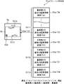
図1は、実施形態における被監視者監視システムの構成を示す図である。図2は、実施形態の被監視者監視システムにおける管理サーバ装置の構成を示す図である。図3は、実施形態の被監視者監視システムにおける携帯端末装置の構成を示す図である。図4は、実施形態の被監視者監視システムにおける管理サーバ装置および携帯端末装置それぞれに記憶される監視情報テーブルの構成を示す図である。
FIG. 1 is a diagram illustrating a configuration of a monitored person monitoring system according to the embodiment. FIG. 2 is a diagram illustrating a configuration of the management server device in the monitored person monitoring system according to the embodiment. FIG. 3 is a diagram illustrating a configuration of the mobile terminal device in the monitored person monitoring system according to the embodiment. FIG. 4 is a diagram illustrating a configuration of a monitoring information table stored in each of the management server device and the mobile terminal device in the monitored person monitoring system according to the embodiment.
実施形態における被監視者監視システムは、監視すべき(見守るべき)監視対象(見守り対象)である被監視者(見守り対象者)Obを監視するものであり、被監視者Obにおける所定の行動を検知して通報するセンサ装置と、所定の情報を表示する表示装置と、前記センサ装置および前記表示装置それぞれと通信可能に接続され、前記センサ装置で検知した検知結果の通報を前記センサ装置から受信して前記表示装置へ前記検知結果を通報する中央処理装置とを備える。
The monitored person monitoring system in the embodiment monitors a monitored person (watched person) Ob that is a monitored object (watched object) to be monitored (watched), and performs a predetermined action on the monitored person Ob. A sensor device that detects and reports, a display device that displays predetermined information, and the sensor device and the display device are communicably connected to each other and receives a notification of a detection result detected by the sensor device from the sensor device. And a central processing unit that reports the detection result to the display device.
このような被監視者監視システムMSは、より具体的には、例えば、図1に示すように、1または複数のセンサ装置SU(SU-1~SU-4)と、管理サーバ装置SVと、固定端末装置SPと、1または複数の携帯端末装置TA(TA-1、TA-2)とを備え、これらは、有線や無線で、LAN(Local Area Network)、電話網およびデータ通信網等の網(ネットワーク、通信回線)NWを介して通信可能に接続される。ネットワークNWには、通信信号を中継する例えばリピーター、ブリッジ、ルーターおよびクロスコネクト等の中継機が備えられても良い。図1に示す例では、これら複数のセンサ装置SU-1~SU-4、管理サーバ装置SV、固定端末装置SPおよび複数の携帯端末装置TA-1、TA-2は、アクセスポイントAPを含む無線LAN(例えばIEEE802.11規格に従ったLAN等)NWによって互いに通信可能に接続されている。
More specifically, such a monitored person monitoring system MS includes, for example, as shown in FIG. 1, one or a plurality of sensor devices SU (SU-1 to SU-4), a management server device SV, A fixed terminal device SP and one or a plurality of portable terminal devices TA (TA-1, TA-2) are provided. These are wired or wireless, such as a LAN (Local Area Network), a telephone network, and a data communication network. Communication is established via a network (network, communication line) NW. The network NW may be provided with relays such as repeaters, bridges, routers, and cross-connects that relay communication signals. In the example shown in FIG. 1, the plurality of sensor devices SU-1 to SU-4, the management server device SV, the fixed terminal device SP, and the plurality of portable terminal devices TA-1 and TA-2 are wireless including an access point AP. A LAN (for example, a LAN according to the IEEE 802.11 standard) NW is connected to be communicable with each other.
なお、後述から明らかなように、センサ装置SUは、前記センサ装置の一例であり、管理サーバ装置SVは、前記中央処理装置の一例であり、前記固定端末装置SPおよび携帯端末装置TAそれぞれは、前記表示装置の一例である。
As will be apparent from the description below, the sensor device SU is an example of the sensor device, the management server device SV is an example of the central processing unit, and the fixed terminal device SP and the mobile terminal device TA are respectively It is an example of the said display apparatus.
被監視者監視システムMSは、被監視者Obに応じて適宜な場所に配設される。被監視者(見守り対象者)Obは、例えば、病気や怪我等によって看護を必要とする者や、身体能力の低下等によって介護を必要とする者や、一人暮らしの独居者等である。特に、早期発見と早期対処とを可能にする観点から、被監視者Obは、例えば異常状態等の所定の不都合な事象がその者に生じた場合にその発見を必要としている者であることが好ましい。このため、被監視者監視システムMSは、被監視者Obの種類に応じて、病院、老人福祉施設および住戸等の建物に好適に配設される。図1に示す例では、被監視者監視システムMSは、複数の被監視者Obが入居する複数の居室RMや、ナースステーション等の複数の部屋を備える介護施設の建物に配設されている。
The monitored person monitoring system MS is arranged at an appropriate place according to the monitored person Ob. The monitored person (person to be watched) Ob is, for example, a person who needs nursing due to illness or injury, a person who needs care due to a decrease in physical ability, a single person living alone, or the like. In particular, from the viewpoint of enabling early detection and early action, the monitored person Ob may be a person who needs the detection when a predetermined inconvenient event such as an abnormal state occurs in the person. preferable. For this reason, the monitored person monitoring system MS is suitably arranged in a building such as a hospital, a welfare facility for the elderly, and a dwelling unit according to the type of the monitored person Ob. In the example illustrated in FIG. 1, the monitored person monitoring system MS is disposed in a building of a care facility that includes a plurality of rooms RM in which a plurality of monitored persons Ob live and a plurality of rooms such as a nurse station.
センサ装置SUは、ネットワークNWを介して他の装置SV、SP、TAと通信する通信機能等を備え、被監視者Obにおける、予め設定された所定の行動を検知してその検知結果を管理サーバ装置SVへ送信する装置である。より具体的には、センサ装置SUは、例えば、ネットワークNWを介して他の装置SV、SP、TAと通信するための通信インターフェース回路(例えばLANカード等)、被監視者Obを撮像して画像を生成する画像センサ、前記画像センサの出力(画像)に基づいて被監視者Obの検知結果として被監視者Obの状態(状況)を判定するデータ処理回路、これらを制御する制御回路およびその周辺回路を備えて構成され、前記検知結果を管理サーバ装置SVへ送信する。また、センサ装置SUは、所定の他の装置SV、SP、TAに前記生成した画像(静止画および動画を含む)を送信する。
The sensor device SU has a communication function that communicates with other devices SV, SP, and TA via the network NW, detects a predetermined action in the monitored person Ob, and manages the detection result. It is a device that transmits to the device SV. More specifically, the sensor device SU, for example, images a communication interface circuit (for example, a LAN card or the like) for communicating with other devices SV, SP, and TA via the network NW and an image of the monitored person Ob. , A data processing circuit for determining the state (situation) of the monitored person Ob as a detection result of the monitored person Ob based on the output (image) of the image sensor, a control circuit for controlling these, and its surroundings The detection result is transmitted to the management server device SV. The sensor device SU transmits the generated image (including still images and moving images) to other predetermined devices SV, SP, and TA.
より詳しくは、前記所定の行動は、本実施形態では、例えば、被監視者Obの起床、離床、転倒および転落である。センサ装置SUは、公知技術によって、被監視者Obを撮像して生成した画像に基づいて被監視者Obの起床、離床、転倒および転落を検知する。例えば、センサ装置SUは、被監視者Obを撮像して生成した画像から例えば背景差分法やフレーム差分法によって被監視者Obの人体領域として動体領域を抽出し、この抽出した動体領域の縦横比(アスペクト比)から被監視者Obの姿勢(例えば立位、座位および横臥等)を判定し、この検出した動体領域の位置を検出し、これら判定、検出した被監視者Obの姿勢および位置に基づいて前記起床、離床、転倒および転落の別を判定する。より詳しくは、センサ装置SUは、例えば、横長なアスペクト比から前記アスペクト比が小さくなるに従って横臥、座位および立位の各姿勢が順次に判定され、ベッド等の寝具上における姿勢が横臥から座位へ変化した場合には起床と判定し、寝具内から立位の姿勢で寝具外へ変化した場合には離床と判定し、寝具の周囲で姿勢が横臥である場合には転落と判定し、そして、前記寝具の周囲の他で姿勢が横臥である場合には転倒と判定する。そして、センサ装置SUは、被監視者Obにおける所定の行動を検知すると、この検知した行動の種類(この例では起床、離床、転倒および転落のうちの1または複数)を表す検知行動情報、前記所定の行動を検知した時刻であるイベント時刻、自機のセンサIDおよび前記検知の際に用いられた静止画(前記検知が複数の画像によって実施された場合には例えば最後の画像)を収容した通信信号(イベント通報通信信号)を管理サーバ装置SVへ送信する。センサID(センサ識別子)は、センサ装置SUを特定しセンサ装置SUを識別するための識別子である。
More specifically, in the present embodiment, the predetermined action is, for example, getting up, getting out of bed, falling, and falling of the monitored person Ob. The sensor device SU detects the wake-up, getting out of bed, falling, and falling of the monitored person Ob based on an image generated by imaging the monitored person Ob by a known technique. For example, the sensor device SU extracts a moving body region as a human body region of the monitored person Ob from an image generated by imaging the monitored person Ob by, for example, the background difference method or the frame difference method, and the aspect ratio of the extracted moving body area From the (aspect ratio), the posture of the monitored person Ob (for example, standing, sitting, lying down, etc.) is determined, the position of the detected moving body region is detected, and the determined and detected posture and position of the monitored person Ob are determined. Based on the above, the distinction between rising, leaving, falling and falling is determined. More specifically, for example, the sensor device SU sequentially determines each posture of lying, sitting and standing as the aspect ratio decreases from a horizontally long aspect ratio, and the posture on the bedding such as a bed changes from lying to sitting. If it changes, it will be determined to wake up, if it changes out of the bedding in a standing posture from inside the bedding, it will be determined to get out of bed, if the posture is lying down around the bedding, it will be determined to fall, and If the posture is lying on the other side of the bedding, it is determined to fall. And if the sensor apparatus SU detects the predetermined | prescribed action in the to-be-monitored person Ob, the detection action information showing the type of this detected action (in this example, one or more of getting up, getting out of bed, falling and falling), Accommodates an event time that is a time when a predetermined action is detected, a sensor ID of the own device, and a still image used in the detection (for example, the last image when the detection is performed by a plurality of images). A communication signal (event notification communication signal) is transmitted to the management server device SV. The sensor ID (sensor identifier) is an identifier for identifying the sensor device SU and identifying the sensor device SU.
なお、センサ装置SUは、固定端末装置SPや携帯端末装置TA等に対してナースコールを通知するナースコール回路、および、固定端末装置SPや携帯端末装置TA等との間で音声通話を行う通話回路を備え、ナースコールおよび音声通話が可能となっていてもよい。
The sensor device SU makes a voice call between the nurse call circuit for notifying the fixed call to the fixed terminal device SP, the portable terminal device TA, etc., and the fixed terminal device SP, the portable terminal device TA, etc. A circuit may be provided to enable nurse calls and voice calls.
図1には、一例として、4個の第1ないし第4センサ装置SU-1~SU-4が示されており、第1センサ装置SU-1は、被監視者Obの一人であるAさんOb-1の居室RM-1(不図示)に配設され、第2センサ装置SU-2は、被監視者Obの一人であるBさんOb-2の居室RM-2(不図示)に配設され、第3センサ装置SU-3は、被監視者Obの一人であるCさんOb-3の居室RM-3(不図示)に配設され、そして、第4センサ装置SU-4は、被監視者Obの一人であるDさんOb-4の居室RM-4(不図示)に配設されている。
FIG. 1 shows four first to fourth sensor devices SU-1 to SU-4 as an example, and the first sensor device SU-1 is one of the monitored persons Ob. The second sensor device SU-2 is arranged in a room RM-2 (not shown) of Mr. B Ob-2 who is one of the monitored persons Ob. The third sensor device SU-3 is disposed in the room RM-3 (not shown) of Mr. C Ob-3, one of the monitored subjects Ob, and the fourth sensor device SU-4 It is arranged in the room RM-4 (not shown) of Mr. D Ob-4, one of the monitored persons Ob.
管理サーバ装置SVは、ネットワークNWを介して他の装置SU、SP、TAと通信する通信機能等を備え、センサ装置SUからイベント通報通信信号を受信して被監視者Obに対する監視に関する情報(監視情報)を管理し、前記受信したイベント通報通信信号を所定の端末装置SP、TAへ通報(再通報、転送、送信)し、端末装置(固定端末装置、携帯端末装置)SP、TAに表示される監視情報の表示を制御し、クライアント(本実施形態では端末装置SP、TA等)の要求に応じたデータを前記クライアントに提供し、被監視者監視システムMS全体を管理する装置である。このような管理サーバ装置SVは、例えば、図2に示すように、サーバ側通信インターフェース部(SV通信IF部)21と、サーバ側制御処理部(SV制御処理部)22と、サーバ側記憶部(SV記憶部)23とを備える。
The management server device SV includes a communication function that communicates with other devices SU, SP, and TA via the network NW, receives information about the event report from the sensor device SU, and monitors information about the monitored person Ob (monitoring). Information), the received event report communication signal is reported (re-reported, transferred, transmitted) to a predetermined terminal device SP, TA, and displayed on the terminal device (fixed terminal device, portable terminal device) SP, TA. This is a device that controls the display of monitoring information and provides the client with data corresponding to the request of the client (terminal device SP, TA, etc. in this embodiment) and manages the entire monitored person monitoring system MS. Such a management server device SV includes, for example, as shown in FIG. 2, a server-side communication interface unit (SV communication IF unit) 21, a server-side control processing unit (SV control processing unit) 22, and a server-side storage unit. (SV storage unit) 23.
SV通信IF部21は、SV制御処理部22に接続され、SV制御処理部22の制御に従って通信を行うための通信回路である。SV通信IF部21は、SV制御処理部22から入力された転送すべきデータを収容した通信信号を、この被監視者監視システムMSのネットワークNWで用いられる通信プロトコルに従って生成し、この生成した通信信号をネットワークNWを介して他の装置SU、SP、TAへ送信する。SV通信IF部21は、ネットワークNWを介して他の装置SU、SP、TAから通信信号を受信し、この受信した通信信号からデータを取り出し、この取り出したデータをSV制御処理部22が処理可能な形式のデータに変換してSV制御処理部22へ出力する。SV通信IF部21は、例えば、IEEE802.11規格等に従った通信インターフェース回路を備えて構成される。
The SV communication IF unit 21 is a communication circuit that is connected to the SV control processing unit 22 and performs communication according to the control of the SV control processing unit 22. The SV communication IF unit 21 generates a communication signal containing data to be transferred input from the SV control processing unit 22 in accordance with a communication protocol used in the network NW of the monitored person monitoring system MS, and the generated communication The signal is transmitted to other devices SU, SP and TA via the network NW. The SV communication IF unit 21 receives communication signals from other devices SU, SP, and TA via the network NW, extracts data from the received communication signals, and the SV control processing unit 22 can process the extracted data. The data is converted into data in a proper format and output to the SV control processing unit 22. The SV communication IF unit 21 includes, for example, a communication interface circuit that complies with the IEEE 802.11 standard or the like.
SV記憶部23は、SV制御処理部22に接続され、SV制御処理部22の制御に従って、各種の所定のプログラムおよび各種の所定のデータを記憶する回路である。前記各種の所定のプログラムには、例えば、管理サーバ装置SVの各部を当該各部の機能に応じてそれぞれ制御するSV制御プログラムや、被監視者Obに対する監視に関する所定の処理を実行するSV監視処理プログラム等の制御処理プログラムが含まれる。前記各種の所定のデータには、自機の、管理サーバ装置SVを特定し管理サーバ装置SVを識別するためのサーバ識別子(サーバID)や、被監視者Obに対する監視に関する監視情報や、前記イベント通報通信信号の通報先等の装置間の情報を表す装置間情報や、センサ装置SUに関するセンサ装置情報等の各プログラムを実行する上で必要なデータ等が含まれる。これら監視情報、装置間情報およびセンサ装置情報それぞれを記憶するために、SV記憶部23は、サーバ側監視情報記憶部(SV監視情報記憶部)231、装置間情報記憶部232およびサーバ側センサ装置情報記憶部(SVセンサ装置情報記憶部)233を機能的に備える。
The SV storage unit 23 is a circuit that is connected to the SV control processing unit 22 and stores various predetermined programs and various predetermined data under the control of the SV control processing unit 22. Examples of the various predetermined programs include an SV control program for controlling each part of the management server device SV in accordance with the function of each part, and an SV monitoring process program for executing a predetermined process related to monitoring of the monitored person Ob. And the like. The various types of predetermined data include a server identifier (server ID) for identifying the management server device SV and identifying the management server device SV, monitoring information related to monitoring of the monitored person Ob, and the event Data necessary for executing each program such as inter-device information indicating information between devices such as a report destination of the notification communication signal and sensor device information related to the sensor device SU is included. In order to store these monitoring information, inter-device information, and sensor device information, the SV storage unit 23 includes a server-side monitoring information storage unit (SV monitoring information storage unit) 231, an inter-device information storage unit 232, and a server-side sensor device. An information storage unit (SV sensor device information storage unit) 233 is functionally provided.
SV監視情報記憶部231は、被監視者Obに対する監視に関する前記監視情報を記憶するものである。前記監視情報は、本実施形態では、イベント通報通信信号に収容された前記検知行動情報による行動の種類(イベント種別、すなわち、本実施形態では起床、離床、転倒および転落)、イベント時刻、センサIDおよび静止画、ならびに、ライブでの動画の取得先としてのセンサ装置SUの通信アドレス(例えばIPアドレス等)、および、被監視者Obに対する例えば救命、看護、介護および介助等の対応(応対、対処)を実行する意思が携帯端末装置TAに入力されたか否かを示す対応情報等を含み、これらは、互いに対応付けられてSV監視情報記憶部231に記憶される。なお、前記イベント時刻に代え、前記イベント通報通信信号の受信時刻が用いられても良い。
The SV monitoring information storage unit 231 stores the monitoring information related to monitoring of the monitored person Ob. In this embodiment, the monitoring information includes the type of action (event type, that is, in this embodiment, getting up, getting out of bed, falling and falling), event time, sensor ID, which is contained in the event notification communication signal. And still image and communication address (for example, IP address) of the sensor device SU as the acquisition source of the live video, and response to the monitored person Ob (for example, lifesaving, nursing, care and assistance) ) Including correspondence information indicating whether or not an intention to execute () is input to the mobile terminal device TA, and these are associated with each other and stored in the SV monitoring information storage unit 231. Instead of the event time, the reception time of the event notification communication signal may be used.
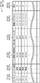
この監視情報は、本実施形態では、テーブル形式でSV監視情報記憶部231に記憶されている。この監視情報を登録する監視情報テーブルMT-SVは、例えば、図4に示すように、前記センサIDを登録するセンサIDフィールド51-SVと、センサIDフィールド51-SVに登録されたセンサIDに対応するセンサ装置SUにかかる前記イベント種別を登録するイベント種別フィールド51-SVと、センサIDフィールド51-SVに登録されたセンサIDに対応するセンサ装置SUにかかる前記イベント時刻を登録するイベント時刻フィールド53-SVと、センサIDフィールド51-SVに登録されたセンサIDに対応するセンサ装置SUにかかる前記静止画を登録する静止画フィールド54-SVと、ライブでの動画の取得先として、センサIDフィールド51-SVに登録されたセンサIDに対応するセンサ装置SUの通信アドレス(例えばIPアドレス等)を登録する動画フィールド55-SVと、センサIDフィールド51-SVに登録されたセンサIDに対応するセンサ装置SUで監視されている被監視者Obに対する前記対応の意思(対応意思、対処意思、対応意思)の入否を示す対応情報を登録する対応フィールド56-SVとを備え、イベント通報通信信号の受信ごとにレコードを備える。対応フィールド56-SVには、前記対応の意思の入否を示す対応情報を示すフラグが登録される。例えば、本実施形態では、対応フィールド56-SVには、前記対応の意思が携帯端末装置TAに入力されたことを意味するフラグ「1」、あるいは、前記対応の意思が携帯端末装置TAに入力されていないことを意味するフラグ「0」が登録される。イベント通報通信信号が受信されて新たなレコードが生成された場合、対応フィールド56-SVには、デフォルト値として「0」が登録される。なお、静止画フィールド54-SVには、例えば、静止画の画像データが登録されて良く、また例えば、静止画の画像データのファイル名が登録されて良い。この図4に示す例では、第1番目のレコードにおいて、各フィールド51-SV~56-SVそれぞれには、「SU-1」、「起床」、「06:32」、「SP1」、「**.**.**.**」(**は整数値)および「0」が登録されている。
In this embodiment, this monitoring information is stored in the SV monitoring information storage unit 231 in a table format. The monitoring information table MT-SV for registering the monitoring information includes, for example, a sensor ID field 51-SV for registering the sensor ID and a sensor ID registered in the sensor ID field 51-SV as shown in FIG. An event type field 51-SV for registering the event type related to the corresponding sensor device SU, and an event time field for registering the event time related to the sensor device SU corresponding to the sensor ID registered in the sensor ID field 51-SV. 53-SV, a still image field 54-SV for registering the still image applied to the sensor device SU corresponding to the sensor ID registered in the sensor ID field 51-SV, and a sensor ID as a live video acquisition source Sensor device S corresponding to sensor ID registered in field 51-SV For the monitored person Ob monitored by the sensor device SU corresponding to the sensor ID registered in the sensor ID field 51-SV and the moving image field 55-SV for registering the communication address (for example, IP address). A correspondence field 56-SV for registering correspondence information indicating whether or not the intention (response intention, response intention, response intention) is entered, and a record for each reception of the event report communication signal. In the correspondence field 56-SV, a flag indicating correspondence information indicating whether or not the corresponding intention is entered is registered. For example, in the present embodiment, in the correspondence field 56-SV, the flag “1” indicating that the intention of correspondence is input to the mobile terminal device TA, or the intention of correspondence is input to the mobile terminal device TA. A flag “0” indicating that it has not been registered is registered. When the event notification communication signal is received and a new record is generated, “0” is registered as a default value in the corresponding field 56-SV. In the still image field 54-SV, for example, still image data may be registered, and for example, a file name of still image data may be registered. In the example shown in FIG. 4, in each of the fields 51-SV to 56-SV in the first record, “SU-1”, “wake-up”, “06:32”, “SP1”, “*” *. **. **. ** ”(** is an integer value) and“ 0 ”are registered.
なお、図4に示す例では、監視情報テーブルMTは、動画フィールド55-SVを備えたが、センサIDと、ライブでの動画の取得先として、センサ装置SUの通信アドレスとの対応関係を示すテーブルが監視情報テーブルMTとは別途に用意されてSV監視情報記憶部231に記憶され、図4に示す監視情報テーブルMTから、動画フィールド55-SVが省略されても良い。
In the example shown in FIG. 4, the monitoring information table MT includes the moving image field 55-SV, but shows a correspondence relationship between the sensor ID and the communication address of the sensor device SU as a live moving image acquisition destination. A table may be prepared separately from the monitoring information table MT and stored in the SV monitoring information storage unit 231, and the moving image field 55-SV may be omitted from the monitoring information table MT shown in FIG.
また、後述するように携帯端末装置TAも監視情報を記憶するために同様の監視情報テーブルMT-TAが記憶されるため、図4には、監視情報テーブルMT-TAの符号も表示されている。
Further, as will be described later, since the mobile terminal device TA also stores the same monitoring information table MT-TA for storing the monitoring information, FIG. 4 also shows the code of the monitoring information table MT-TA. .
装置間情報記憶部232は、前記イベント通報通信信号の通報先等の装置間の情報を表す前記装置間情報を予め記憶するものである。装置間情報記憶部232は、前記装置間情報として、本実施形態では、イベント通報通信信号の送信元であるセンサIDと前記イベント通報通信信号の通報先(再通報先、転送先、送信先)である端末IDとの対応関係(通報先対応関係)、および、各装置SU、SP、TAのID(センサID、端末ID)とその通信アドレスとの対応関係(通信アドレス対応関係)等を記憶する。端末IDは、端末装置SP、TAを特定し端末装置SP、TAを識別するための端末識別子である。なお、センサID、サーバIDおよび端末IDそれぞれは、例えば所定の記号列から成るシリアル番号等であって良く、また例えば通信アドレスであって良い(この場合通信アドレス対応関係は省略できる)。
The inter-device information storage unit 232 stores in advance the inter-device information representing information between devices, such as a notification destination of the event notification communication signal. The inter-device information storage unit 232, as the inter-device information, in this embodiment, the sensor ID that is the transmission source of the event notification communication signal and the notification destination (re-report destination, transfer destination, transmission destination) of the event notification communication signal. And the correspondence relationship (terminal ID correspondence) of each device SU, SP, and TA (sensor ID, terminal ID) and the communication address (communication address correspondence), etc. To do. The terminal ID is a terminal identifier for identifying the terminal devices SP and TA and identifying the terminal devices SP and TA. Note that each of the sensor ID, server ID, and terminal ID may be, for example, a serial number composed of a predetermined symbol string, or may be a communication address (in this case, communication address correspondence can be omitted).
SVセンサ装置情報記憶部233は、センサ装置SUに関する前記センサ装置情報を予め記憶するものである。SVセンサ装置情報記憶部233は、前記センサ装置情報として、本実施形態では、センサIDと、センサIDに対応するセンサ装置SUの配設場所を表す情報(配置場所情報)と、センサIDに対応するセンサ装置SUによって監視されている被監視者Obの氏名との対応関係等を記憶する。
The SV sensor device information storage unit 233 stores the sensor device information related to the sensor device SU in advance. In the present embodiment, the SV sensor device information storage unit 233 corresponds to the sensor ID, information indicating the location of the sensor device SU corresponding to the sensor ID (location location information), and the sensor ID. The correspondence relationship with the name of the monitored person Ob monitored by the sensor device SU is stored.
SV制御処理部22は、管理サーバ装置SVの各部を当該各部の機能に応じてそれぞれ制御し、センサ装置SUからイベント通報通信信号を受信して被監視者Obに対する監視に関する前記監視情報を管理し、前記受信したイベント通報通信信号を所定の端末装置SP、TAへ通報し、クライアント(本実施形態では端末装置SP、TA等)の要求に応じたデータを前記クライアントに提供し、被監視者監視システムMS全体を管理するための回路である。SV制御処理部22は、例えば、CPUおよびその周辺回路を備えて構成される。SV制御処理部22は、前記制御処理プログラムが実行されることによって、サーバ側制御部(SV制御部)221およびサーバ側監視処理部(SV監視処理部)222を機能的に備える。
The SV control processing unit 22 controls each part of the management server device SV according to the function of each part, receives an event notification communication signal from the sensor device SU, and manages the monitoring information related to monitoring the monitored person Ob. The received event notification communication signal is notified to a predetermined terminal device SP, TA, and data corresponding to the request of the client (in this embodiment, the terminal device SP, TA, etc.) is provided to the client to monitor the monitored person. This is a circuit for managing the entire system MS. The SV control processing unit 22 includes, for example, a CPU and its peripheral circuits. The SV control processing unit 22 functionally includes a server side control unit (SV control unit) 221 and a server side monitoring processing unit (SV monitoring processing unit) 222 by executing the control processing program.
SV制御部221は、管理サーバ装置SVの各部を当該各部の機能に応じてそれぞれ制御し、管理サーバ装置SVの全体制御を司るものである。
The SV control unit 221 controls each unit of the management server device SV according to the function of each unit, and controls the entire management server device SV.
SV監視処理部222は、センサ装置SUからイベント通報通信信号を受信した場合に、被監視者Obに対する監視に関する監視情報をSV監視情報記憶部231に記憶(記録)し、前記受信したイベント通報通信信号を送信したセンサ装置SUに対応する通報先(再通報先、転送先、送信先)を装置間情報記憶部232に記憶された前記通報先対応関係から選定(検索)し、この選定した端末装置SP、TAへ前記イベント通報通信信号を送信するものである。この選定(検索処理)は、前記受信したイベント通報通信信号を送信したセンサ装置SUに対応するセンサIDに基づいて実施される。ここで、前記再通報されるイベント通報通信信号には、動画のダウンロード先として、前記受信したイベント通報通信信号を送信したセンサ装置SUに対応する通信アドレスがさらに収容される。この通信アドレスは、前記受信したイベント通報通信信号を送信したセンサ装置SUに対応するセンサIDに基づいて前記通信アドレス対応関係から選定(検索)される。SV監視処理部222は、SVセンサ装置情報記憶部233に記憶されている前記センサ装置情報を、それを収容した通信信号によって、携帯端末装置TAへ送信する。このセンサ装置情報の送信は、例えば、後述の携帯端末装置TAのログインの際等に実施される。そして、SV監視処理部222は、端末装置SP、TAからSV通信IF部21で、被監視者Obに対し対応意思を受け付けた旨を通知するための通信信号である対応通知通信信号を受信した場合に、対応意思の受付済みをSV監視情報記憶部231に記憶し、対応意思を受け付けた被監視者Obの検知結果を表示させないための通信信号である対応不要通知通信信号を同報通信でSV通信IF部21から送信する。同報通信は、例えば、被監視者監視システムMSにおける全ての端末装置SP、TA宛に送信するブロードキャストであって良く、また例えば被監視者監視システムMSにおける所定の複数の端末装置SP、TA宛に送信するマルチキャストであって良い。
When the SV monitoring processing unit 222 receives an event notification communication signal from the sensor device SU, the SV monitoring processing unit 222 stores (records) monitoring information related to monitoring of the monitored person Ob in the SV monitoring information storage unit 231, and receives the received event notification communication The reporting destination (re-reporting destination, transfer destination, transmission destination) corresponding to the sensor device SU that transmitted the signal is selected (searched) from the reporting destination correspondence stored in the inter-device information storage unit 232, and the selected terminal The event notification communication signal is transmitted to the devices SP and TA. This selection (search process) is performed based on the sensor ID corresponding to the sensor device SU that has transmitted the received event notification communication signal. Here, the re-reported event report communication signal further contains a communication address corresponding to the sensor device SU that transmitted the received event report communication signal as a download destination of the moving image. This communication address is selected (searched) from the communication address correspondence based on the sensor ID corresponding to the sensor device SU that has transmitted the received event notification communication signal. The SV monitoring processing unit 222 transmits the sensor device information stored in the SV sensor device information storage unit 233 to the mobile terminal device TA by a communication signal containing the sensor device information. The transmission of the sensor device information is performed, for example, at the time of login of a mobile terminal device TA described later. Then, the SV monitoring processing unit 222 has received a response notification communication signal, which is a communication signal for notifying the monitored person Ob that the intention of response has been received by the SV communication IF unit 21 from the terminal devices SP and TA. In such a case, the information indicating that the response to the response has been received is stored in the SV monitoring information storage unit 231, and a response signal indicating that the response is not required is not displayed by the broadcast communication. It is transmitted from the SV communication IF unit 21. The broadcast communication may be, for example, a broadcast transmitted to all terminal devices SP and TA in the monitored person monitoring system MS, and for example, a predetermined plurality of terminal devices SP and TA in the monitored person monitoring system MS It may be a multicast to be transmitted to.
なお、管理サーバ装置SVは、図2に破線で示すように、必要に応じて、さらに、SV制御処理部22に接続され例えば各種コマンドや各種データ等を入力するサーバ側入力部(SV入力部)24、SV入力部24で入力された各種コマンドや各種データおよび被監視者Obに対する監視に関する監視情報等を出力するサーバ側出力部(SV出力部)25、および、外部機器との間でデータの入出力を行うサーバ側インターフェース部(SVIF部)26等を備えても良い。
The management server device SV is connected to the SV control processing unit 22 as necessary, as shown by a broken line in FIG. 2, for example, a server side input unit (SV input unit) for inputting various commands, various data, and the like. 24) Server side output unit (SV output unit) 25 that outputs various commands and various data input by the SV input unit 24 and monitoring information related to monitoring of the monitored person Ob, and data between external devices A server-side interface unit (SVIF unit) 26 or the like for performing input / output may be provided.
このような管理サーバ装置SVは、例えば、通信機能付きのコンピュータによって構成可能である。
Such a management server device SV can be configured by a computer with a communication function, for example.
固定端末装置SPは、ネットワークNWを介して他の装置SU、SV、TAと通信する通信機能、所定の情報を表示する表示機能、および、所定の指示やデータを入力する入力機能等を備え、管理サーバ装置SVや携帯端末装置TAに与える所定の指示やデータを入力したり、センサ装置SUで得られた監視情報を表示したり等することによって、被監視者監視システムMSのユーザインターフェース(UI)として機能する機器である。このような固定端末装置SPは、例えば、通信機能付きのコンピュータによって構成可能である。なお、前記端末装置の一例としての固定端末装置SPは、携帯端末装置TAと同様に動作するが、本明細書では、前記端末装置の一実施形態は、その一例である携帯端末装置TAについて説明される。
The fixed terminal device SP includes a communication function for communicating with other devices SU, SV, TA via the network NW, a display function for displaying predetermined information, an input function for inputting predetermined instructions and data, and the like. The user interface (UI) of the monitored person monitoring system MS is input by inputting predetermined instructions and data to be given to the management server device SV and the portable terminal device TA, or displaying the monitoring information obtained by the sensor device SU. ). Such a fixed terminal device SP can be configured by, for example, a computer with a communication function. The fixed terminal device SP as an example of the terminal device operates in the same manner as the mobile terminal device TA. However, in the present specification, an embodiment of the terminal device is described as an example of the mobile terminal device TA. Is done.
携帯端末装置TAは、ネットワークNWを介して他の装置SV、SP、SUと通信する通信機能、所定の情報を表示する表示機能、所定の指示やデータを入力する入力機能、および、音声通話を行う通話機能等を備え、管理サーバ装置SVやセンサ装置SUに与える所定の指示やデータを入力したり、管理サーバ装置SVからの通報によってセンサ装置SUで得られた監視情報(動画を含む)を表示したり、センサ装置SUとの間で音声通話したり等することによって、被監視者Obに対する前記監視情報の通報を受け付けて表示するための機器である。このような携帯端末装置TAは、本実施形態では、例えば、図3に示すように、端末側通信インターフェース部(TA通信IF部)31と、端末側制御処理部(TA制御処理部)32と、端末側記憶部(TA記憶部)33と、端末側音入出力部(TA音入出力部)34と、端末側入力部(TA入力部)35と、端末側表示部(TA表示部)36と、端末側インターフェース部(TAIF部)37とを備える。
The mobile terminal device TA has a communication function for communicating with other devices SV, SP, SU via the network NW, a display function for displaying predetermined information, an input function for inputting predetermined instructions and data, and a voice call. A monitoring function (including a moving image) obtained by the sensor device SU by inputting a predetermined instruction or data to be provided to the management server device SV or the sensor device SU or a report from the management server device SV. This is a device for receiving and displaying a report of the monitoring information to the monitored person Ob by displaying or making a voice call with the sensor device SU. In the present embodiment, for example, as shown in FIG. 3, such a mobile terminal device TA includes a terminal-side communication interface unit (TA communication IF unit) 31, a terminal-side control processing unit (TA control processing unit) 32, and A terminal side storage unit (TA storage unit) 33, a terminal side sound input / output unit (TA sound input / output unit) 34, a terminal side input unit (TA input unit) 35, and a terminal side display unit (TA display unit). 36 and a terminal-side interface unit (TAIF unit) 37.
TA音入出力部34は、TA制御処理部32に接続され、外部の音を取得して携帯端末装置TAに入力するためのデバイスであって、TA制御処理部32の制御に従って音を表す電気信号に応じた音を生成して出力するためのデバイスである。TA音入出力部34は、SU音入出力部12と同様に、例えば、音響振動を電気信号に変換するマイクロホン等と、音の電気信号を音の音響振動に変換するスピーカ等とを備えて構成される。TA音入出力部34は、外部の音を表す電気信号をTA制御処理部32へ出力し、また、TA制御処理部32から入力された電気信号を音の音響振動に変換して出力する。
The TA sound input / output unit 34 is connected to the TA control processing unit 32 and is a device for acquiring an external sound and inputting it to the mobile terminal device TA. It is a device for generating and outputting sound corresponding to a signal. Similar to the SU sound input / output unit 12, the TA sound input / output unit 34 includes, for example, a microphone that converts acoustic vibration into an electric signal, and a speaker that converts an electric signal of sound into an acoustic vibration of sound. Composed. The TA sound input / output unit 34 outputs an electric signal representing an external sound to the TA control processing unit 32, and converts the electric signal input from the TA control processing unit 32 into sound acoustic vibration and outputs the sound.
TA入力部35は、TA制御処理部32に接続され、例えば、所定の操作を受け付け、携帯端末装置TAに入力するデバイスであり、例えば、所定の機能を割り付けられた複数の入力スイッチ等である。前記所定の操作には、例えば、ログインするためのIDの入力操作や、音声通話の要求操作およびその終了操作や、ライブでの動画の要求操作およびその終了操作や、前記通報された被監視者Obに対する例えば救命、看護、介護および介助等の前記対応を実行する意思がある旨(“対応する”)の入力操作等の、監視する上で必要な各種操作等が含まれる。TA表示部36は、TA制御処理部32に接続され、TA制御処理部32の制御に従って、TA入力部35から入力された所定の操作内容、および、被監視者監視システムMSによって監視されている被監視者Obに対する監視に関する前記監視情報(例えばセンサ装置SUで検知した所定の行動の種類や被監視者Obの画像(静止画および動画)等)等を表示するデバイスであり、例えばLCD(液晶ディスプレイ)および有機ELディスプレイ等の表示装置である。そして、本実施形態では、TA入力部35およびTA表示部36からタッチパネルが構成されている。この場合において、TA入力部35は、例えば抵抗膜方式や静電容量方式等の操作位置を検出して入力する位置入力デバイスである。このタッチパネルでは、TA表示部36の表示面上に位置入力デバイスが設けられ、TA表示部36に入力可能な1または複数の入力内容の候補が表示され、例えば看護師や介護士等のユーザ(監視者)が、入力したい入力内容を表示した表示位置を触れると、位置入力デバイスによってその位置が検出され、検出された位置に表示された表示内容がユーザの操作入力内容として携帯端末装置TAに入力される。
The TA input unit 35 is connected to the TA control processing unit 32 and is, for example, a device that accepts a predetermined operation and inputs it to the mobile terminal device TA, for example, a plurality of input switches assigned with a predetermined function. . Examples of the predetermined operation include an ID input operation for logging in, a voice call request operation and its end operation, a live video request operation and its end operation, and the reported monitored person. For example, various operations necessary for monitoring, such as an input operation indicating that there is an intention to perform the above-described response to the Ob, such as lifesaving, nursing, care, and assistance ("corresponding") are included. The TA display unit 36 is connected to the TA control processing unit 32, and is monitored by the monitored person monitoring system MS according to predetermined operation contents input from the TA input unit 35 according to the control of the TA control processing unit 32. It is a device that displays the monitoring information related to monitoring of the monitored person Ob (for example, the type of a predetermined action detected by the sensor device SU, an image (still image and moving image) of the monitored person Ob), etc. Display) and a display device such as an organic EL display. In the present embodiment, the TA input unit 35 and the TA display unit 36 constitute a touch panel. In this case, the TA input unit 35 is a position input device that detects and inputs an operation position such as a resistance film method or a capacitance method. In this touch panel, a position input device is provided on the display surface of the TA display unit 36, and one or more input content candidates that can be input are displayed on the TA display unit 36. For example, a user such as a nurse or a caregiver ( When the monitor) touches the display position where the input content to be input is displayed, the position is detected by the position input device, and the display content displayed at the detected position is input to the portable terminal device TA as the operation input content of the user. Entered.
TAIF部37は、TA制御処理部32に接続され、TA制御処理部32の制御に従って、外部機器との間でデータの入出力を行うデバイスであり、例えば、Bluetooth(登録商標)規格を用いたインターフェース回路、IrDA規格等の赤外線通信を行うインターフェース回路、および、USB規格を用いたインターフェース回路等である。
The TAIF unit 37 is a device that is connected to the TA control processing unit 32 and inputs / outputs data to / from an external device according to the control of the TA control processing unit 32. For example, the TAIF unit 37 uses the Bluetooth (registered trademark) standard. An interface circuit, an interface circuit that performs infrared communication such as the IrDA standard, and an interface circuit that uses the USB standard.
TA通信IF部31は、SV通信IF部21と同様に、TA制御処理部32に接続され、TA制御処理部32の制御に従って通信を行うための通信デバイスである。TA通信IF部31は、TA制御処理部32から入力された転送すべきデータを収容した通信信号を、この被監視者監視システムMSのネットワークNWで用いられる通信プロトコルに従って生成し、この生成した通信信号をネットワークNWを介して他の装置SU、SV、SPへ送信する。TA通信IF部31は、ネットワークNWを介して他の装置SU、SV、SPから通信信号を受信し、この受信した通信信号からデータを取り出し、この取り出したデータをTA制御処理部32が処理可能な形式のデータに変換してTA制御処理部32へ出力する。TA通信IF部31は、例えば、IEEE802.11規格等に従った通信インターフェース回路を備えて構成される。
The TA communication IF unit 31 is a communication device that is connected to the TA control processing unit 32 and performs communication according to the control of the TA control processing unit 32, similarly to the SV communication IF unit 21. The TA communication IF unit 31 generates a communication signal containing the data to be transferred input from the TA control processing unit 32 in accordance with the communication protocol used in the network NW of the monitored person monitoring system MS, and the generated communication The signal is transmitted to other devices SU, SV, SP via the network NW. The TA communication IF unit 31 receives a communication signal from another device SU, SV, SP via the network NW, extracts data from the received communication signal, and the TA control processing unit 32 can process the extracted data. The data is converted into data of a proper format and output to the TA control processing unit 32. The TA communication IF unit 31 includes, for example, a communication interface circuit that conforms to the IEEE 802.11 standard or the like.
TA記憶部33は、TA制御処理部32に接続され、TA制御処理部32の制御に従って、各種の所定のプログラムおよび各種の所定のデータを記憶する回路である。前記各種の所定のプログラムには、例えば、携帯端末装置TAの各部を当該各部の機能に応じてそれぞれ制御するTA制御プログラムや、被監視者Obに対する監視に関する所定の処理を実行するTA監視処理プログラムや、TA音入出力部12等を用いることでセンサ装置SUとの間で音声通話を行うTA音声通話処理プログラムや、センサ装置SUから動画の配信を受け、前記配信を受けた動画をストリーミング再生でTA表示部36に表示するTAストリーミング処理プログラム等の制御処理プログラムが含まれる。前記TA監視処理プログラムには、被監視者Obに対する監視に関する所定の処理の一つとして、管理サーバ装置SVから再通報のイベント通報通信信号を受信した場合に、この受信した再通報のイベント通報通信信号に収容された各情報に応じた画面をTA表示部36に表示する表示処理プログラムが含まれる。前記各種の所定のデータでは、自機の端末ID、TA表示部36に表示される表示画面情報、被監視者Obに対する監視に関する前記監視情報、および、センサ装置SUに関する前記センサ装置情報等の各プログラムを実行する上で必要なデータ等が含まれる。TA記憶部33は、例えばROMやEEPROM等を備える。TA記憶部33は、前記所定のプログラムの実行中に生じるデータ等を記憶するいわゆるTA制御処理部32のワーキングメモリとなるRAM等を含む。そして、TA記憶部33は、前記表示画面情報、前記監視情報および前記センサ装置情報それぞれを記憶するために、表示画面記憶部331、端末側監視情報記憶部(TA監視情報記憶部)332、および、端末側センサ装置情報記憶部333を機能的に備える。
The TA storage unit 33 is a circuit that is connected to the TA control processing unit 32 and stores various predetermined programs and various predetermined data under the control of the TA control processing unit 32. Examples of the various predetermined programs include a TA control program for controlling each part of the mobile terminal device TA according to the function of each part, and a TA monitoring process program for executing a predetermined process related to monitoring of the monitored person Ob. In addition, a TA voice call processing program for making a voice call with the sensor device SU by using the TA sound input / output unit 12 or the like, or distribution of a video from the sensor device SU, and streaming playback of the received video A control processing program such as a TA streaming processing program displayed on the TA display unit 36 is included. In the TA monitoring processing program, as one of the predetermined processes relating to monitoring of the monitored person Ob, when a re-report event notification communication signal is received from the management server device SV, the received re-report event notification communication is received. A display processing program for displaying a screen corresponding to each piece of information contained in the signal on the TA display unit 36 is included. In the various predetermined data, each of the terminal ID of the own device, the display screen information displayed on the TA display unit 36, the monitoring information related to monitoring of the monitored person Ob, the sensor device information related to the sensor device SU, etc. Data necessary for executing the program is included. The TA storage unit 33 includes, for example, a ROM and an EEPROM. The TA storage unit 33 includes a RAM serving as a working memory for the so-called TA control processing unit 32 that stores data generated during execution of the predetermined program. The TA storage unit 33 stores the display screen information, the monitoring information, and the sensor device information, respectively, a display screen storage unit 331, a terminal-side monitoring information storage unit (TA monitoring information storage unit) 332, and The terminal side sensor device information storage unit 333 is functionally provided.
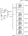
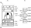
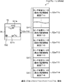
表示画面記憶部331は、TA制御処理部32における後述の表示処理部3221の制御に従って、TA表示部36に表示するための表示画面等の画像を記憶するものであり、例えばVRAM(ビデオメモリ)等である。表示画面記憶部331は、複数の被監視者Obそれぞれに関する各監視情報を表す後述の監視情報画面が複数ある場合には、これら複数の監視情報画面を所定の序列で関係付けて記憶する。これら前記所定の序列で互いに関係付けられた複数の監視情報画面等、TA入力部35で受け付けられた、表示内容(表示画面)を切り換えるための入力操作(切換操作)に応じて、一方の監視情報画面から他方の監視情報画面へ選択的に切り換えることで、TA表示部46に表示されて良く、また、TA入力部35で受け付けられた切換操作に応じて、連続的に表示されつつ一方の監視情報画面から他方の監視情報画面へ移行することで、TA表示部36に表示されて良い。本実施形態では、より具体的には、互いに異なる複数の被監視者Obそれぞれに関するイベント通報通信信号が受信されると、前記複数のイベント通報通信信号それぞれに対応する複数の監視情報画面は、互いに前記所定の序列で連結されてプレーンに形成される。より詳しくは、前記複数の監視情報画面は、例えば、本実施形態では、TA表示部36に表示された場合の上下方向に前記所定の序列で連結されてプレーンに形成される。なお、前記上下方向に代え、左右方向であっても良い。そして、表示画面記憶部331に記憶されるプレーンサイズは、通常、TA表示部36の画面表示領域のサイズと同等であるが、複数のイベント通報通信信号が受信されると、1つのイベント通報通信信号に関する監視情報画面は、前記通常のプレーンサイズで形成され、前記複数のイベント通報通信信号それぞれに対応する複数の監視情報画面は、前記所定の序列で互いに連結されてプレーンに形成されるので、この複数のイベント通報通信信号が受信された場合のプレーンサイズは、複数の監視情報画面の個数に応じたサイズとなる。このプレーンに形成された複数の監視情報画面のうち、TA表示部36の画面表示領域のサイズに応じた部分だけが、TA監視処理部322における表示処理部3221の制御によって、TA入力部35で受け付けた入力操作に応じてTA表示部36に表示される。そして、TA表示部36に表示されている画面には、新たに受信したイベント通報通信信号にかかる監視情報の存在を表す符号である新着監視情報表示がさらに表示される。
The display screen storage unit 331 stores an image such as a display screen to be displayed on the TA display unit 36 in accordance with control of a display processing unit 3221 described later in the TA control processing unit 32, for example, a VRAM (video memory). Etc. In the case where there are a plurality of monitoring information screens to be described later that represent each piece of monitoring information regarding each of the plurality of monitored subjects Ob, the display screen storage unit 331 stores the plurality of monitoring information screens in a predetermined order. In accordance with an input operation (switching operation) for switching display contents (display screen) accepted by the TA input unit 35, such as a plurality of monitoring information screens related to each other in the predetermined order, one of the monitoring information screens By selectively switching from the information screen to the other monitoring information screen, it may be displayed on the TA display unit 46, and one of the monitoring screens is continuously displayed in response to the switching operation accepted by the TA input unit 35. By shifting from the monitoring information screen to the other monitoring information screen, it may be displayed on the TA display unit 36. In this embodiment, more specifically, when an event notification communication signal regarding each of a plurality of different monitored persons Ob is received, a plurality of monitoring information screens corresponding to the plurality of event notification communication signals are mutually The planes are connected in the predetermined order to form a plane. More specifically, for example, in the present embodiment, the plurality of monitoring information screens are formed in a plane by being connected in the predetermined order in the vertical direction when displayed on the TA display unit 36. In addition, it may replace with the said up-down direction and may be the left-right direction. The plane size stored in the display screen storage unit 331 is usually equal to the size of the screen display area of the TA display unit 36. However, when a plurality of event notification communication signals are received, one event notification communication is performed. The monitoring information screen related to the signal is formed in the normal plane size, and the plurality of monitoring information screens corresponding to each of the plurality of event notification communication signals are connected to each other in the predetermined order and formed in a plane. The plane size when the plurality of event notification communication signals are received is a size corresponding to the number of the plurality of monitoring information screens. Of the plurality of monitoring information screens formed on this plane, only the portion corresponding to the size of the screen display area of the TA display unit 36 is controlled by the TA input unit 35 under the control of the display processing unit 3221 in the TA monitoring processing unit 322. It is displayed on the TA display unit 36 according to the accepted input operation. The screen displayed on the TA display unit 36 further displays a new arrival monitoring information display, which is a code indicating the presence of the monitoring information related to the newly received event notification communication signal.
TA監視情報記憶部332は、被監視者Obに対する監視に関する前記監視情報を記憶するものであり、SV監視情報記憶部231と同様の前記監視情報を、SV監視情報記憶部231と同様の、図4に示す監視情報テーブルMT-TAによってテーブル形式で記憶する。
The TA monitoring information storage unit 332 stores the monitoring information related to the monitoring of the monitored person Ob, and the monitoring information similar to the SV monitoring information storage unit 231 is similar to the SV monitoring information storage unit 231. 4 is stored in the table format by the monitoring information table MT-TA shown in FIG.
TAセンサ装置情報記憶部333は、センサ装置SUに関する前記センサ装置情報を予め記憶するものであり、管理サーバ装置SVから前記センサ装置情報を受信することによって、SVセンサ装置情報記憶部233と同様の前記センサ装置情報を記憶する。
The TA sensor device information storage unit 333 stores the sensor device information related to the sensor device SU in advance, and receives the sensor device information from the management server device SV. The sensor device information is stored.
TA制御処理部32は、携帯端末装置TAの各部を当該各部の機能に応じてそれぞれ制御し、被監視者Obに対する前記監視情報を受け付けて表示するための回路である。TA制御処理部32は、SV制御処理部22と同様に、例えば、CPUおよびその周辺回路を備えて構成される。TA制御処理部32は、制御処理プログラムが実行されることによって、端末側制御部(TA制御部)321、端末側監視処理部(TA監視処理部)322、端末側音声通話処理部(TA音声通話処理部)323および端末側ストリーミング処理部324を機能的に備え、TA監視処理部322は、表示処理部3221を機能的に備える。
The TA control processing unit 32 is a circuit for controlling each part of the mobile terminal device TA according to the function of each part and receiving and displaying the monitoring information for the monitored person Ob. Similar to the SV control processing unit 22, the TA control processing unit 32 includes, for example, a CPU and its peripheral circuits. The TA control processing unit 32 executes a control processing program, so that a terminal side control unit (TA control unit) 321, a terminal side monitoring processing unit (TA monitoring processing unit) 322, a terminal side voice call processing unit (TA voice) Call processing unit) 323 and terminal-side streaming processing unit 324 are functionally provided, and the TA monitoring processing unit 322 is functionally provided with a display processing unit 3221.
TA制御部321は、携帯端末装置TAの各部を当該各部の機能に応じてそれぞれ制御し、携帯端末装置TAの全体制御を司るものである。
The TA control unit 321 controls each part of the mobile terminal apparatus TA according to the function of each part, and controls the entire mobile terminal apparatus TA.
TA監視処理部322は、被監視者Obに対する監視に関する所定の処理を実行するものである。より具体的には、TA監視処理部322は、管理サーバ装置SVから再通報のイベント通報通信信号を受信した場合に、この受信したイベント通報通信信号に収容された各情報(各データ)に基づき、被監視者Obに対する監視に関する前記監視情報をTA監視情報記憶部332に記憶(記録)する。そして、TA監視処理部322は、TA入力部35で所定の入力操作を受け付けると、その入力操作に応じた所定の処理を実行する。より詳しくは、例えば、TA監視処理部322は、TA入力部35で前記切換指示を受け付けると、表示処理部3221によって、前記切換指示に応じた監視情報画面をTA表示部36に表示する。また例えば、TA監視処理部322は、再通報されたイベント通報通信信号にかかる被監視者Obに対する例えば救命、看護、介護および介助等の前記対応を実行する意思がある旨(“対応する”)を当該携帯端末装置TAに入力するための入力操作を受け付けると(すなわち、前記対応意思を受け付けると)、表示処理部3221によって、被監視者Obに対し前記対応意思を受け付けた旨を通知するための通信信号である対応通知通信信号を他の端末装置SP、TAへ管理サーバ装置SVを介して通報する。また例えば、TA監視処理部322は、音声通話を要求するための入力操作をTA入力部35から受け付けると、TA音声通話処理部323によって、センサ装置SUへ音声通話を要求してセンサ装置SUとの間で音声通話を行い、その終了の入力操作をTA入力部35から受け付けると、TA音声通話処理部323によって、センサ装置SUへ音声通話の終了を要求してセンサ装置SUとの間での音声通話を終了する。また例えば、TA監視処理部322は、ライブでの動画を要求するための入力操作をTA入力部35から受け付けると、TAストリーミング処理部324によって、センサ装置SUへ動画の配信を要求して動画をTA表示部36に表示し、その終了の入力操作をTA入力部35から受け付けると、TAストリーミング処理部324によって、センサ装置SUへ動画の配信の停止を要求してTA表示部36での動画の表示を終了する。
The TA monitoring processing unit 322 executes predetermined processing related to monitoring of the monitored person Ob. More specifically, when the TA monitoring processing unit 322 receives an event notification communication signal for re-reporting from the management server device SV, the TA monitoring processing unit 322 is based on each information (each data) accommodated in the received event notification communication signal. The monitoring information related to the monitoring of the monitored person Ob is stored (recorded) in the TA monitoring information storage unit 332. Then, when receiving a predetermined input operation at the TA input unit 35, the TA monitoring processing unit 322 executes a predetermined process corresponding to the input operation. More specifically, for example, when the TA monitoring processing unit 322 receives the switching instruction through the TA input unit 35, the display processing unit 3221 displays a monitoring information screen corresponding to the switching instruction on the TA display unit 36. In addition, for example, the TA monitoring processing unit 322 has an intention to execute the above-described response such as lifesaving, nursing, care, and assistance to the monitored person Ob related to the re-reported event notification communication signal (“correspond”). Is received by the display processing unit 3221 to notify the person to be monitored that the response intention has been received. Is notified to the other terminal devices SP and TA via the management server device SV. Also, for example, when the TA monitoring processing unit 322 receives an input operation for requesting a voice call from the TA input unit 35, the TA voice call processing unit 323 requests the sensor device SU to make a voice call with the sensor device SU. When the TA input unit 35 accepts an input operation for terminating the voice call, the TA voice call processing unit 323 requests the sensor device SU to end the voice call, and communicates with the sensor device SU. End the voice call. Further, for example, when the TA monitoring processing unit 322 receives an input operation for requesting a live video from the TA input unit 35, the TA streaming processing unit 324 requests distribution of the video to the sensor device SU by the TA streaming processing unit 324. When it is displayed on the TA display unit 36 and an input operation for the end is received from the TA input unit 35, the TA streaming processing unit 324 requests the sensor device SU to stop the distribution of the moving image and displays the moving image on the TA display unit 36. End the display.
表示処理部3221は、管理サーバ装置SVから再通報のイベント通報通信信号を受信した場合に、この受信した再通報のイベント通報通信信号に収容された各情報に応じた画面を所定の処理に従ってTA表示部36に表示するものである。より具体的には、表示処理部3221は、1人の被監視者Obに関する監視情報を表す1つの監視情報画面がある場合、この監視情報画面を表示画面記憶部331に記憶し、TA表示部36に表示する。表示処理部3221は、複数の被監視者Obそれぞれに関する各監視情報を表す複数の監視情報画面がある場合、これら複数の監視情報画面を所定の序列で関係付けて表示画面記憶部331に記憶し、前記複数の監視情報画面のうちの所定の画面をTA表示部36に表示する。より詳しくは、本実施形態では、表示処理部3221は、これら複数の監視情報画面を前記所定の序列で互いに連結してプレーンを形成して表示画面記憶部331に記憶し、前記複数の監視情報画面のうちの所定の画面をTA表示部36に表示する。さらにより詳しくは、表示処理部3221は、TA通信IF部31を介してイベント通報通信信号の通報を新たに受信した場合、TA表示部36に表示されている既存の表示内容を維持し、この新たに受信したイベント通報通信信号にかかる監視情報の存在を表す符号である前記新着監視情報表示(例えば二重丸マーク532(◎532;図6参照)等をTA表示部36にさらに表示し、TA入力部36で前記切換指示を受け付けた場合に、この新たに受信したイベント通報通信信号の監視情報をTA表示部36に表示する。好ましくは、表示処理部3221は、TA入力部36で前記切換指示を受け付けた場合に、前記既存の表示内容から前記新たに受信したイベント通報通信信号の監視情報までの間において、既に受信している複数のイベント通報通信信号にかかる複数の監視情報を全て表示した後に、この新たに受信したイベント通報通信信号の監視情報をTA表示部36に表示する。表示処理部3221は、この新たに受信したイベント通報通信信号の監視情報をTA表示部36に表示すると、前記新着監視情報表示532をTA表示部36から消去し、TA表示部36に表示しない。表示処理部3221は、TA入力部35で前記対応意思を受け付けた場合に、前記対応意思を受け付けた被監視者Obの監視情報をTA表示部36に表示しない。表示処理部3221は、TA入力部35で前記対応意思を受け付けた場合に、被監視者Obに対し前記対応意思を受け付けた旨を通知するための通信信号である前記対応通知通信信号をTA通信IF部31から管理サーバ装置SVへ送信し、対応意思を受け付けた被監視者Obの監視情報を表示させないための通信信号である対応不要通知通信信号を受信した場合に、この受信した対応不要通知通信信号にかかる被監視者Obの監視情報をTA表示部36に表示しない。好ましくは、前記所定の序列は、本実施形態では、時系列順であり、表示処理部3221は、時系列順に順次に切り換える。
When the display processing unit 3221 receives a rereport event notification communication signal from the management server device SV, the display processing unit 3221 displays a screen corresponding to each piece of information contained in the received rereport event notification communication signal according to a predetermined process. It is displayed on the display unit 36. More specifically, when there is one monitoring information screen representing monitoring information related to one monitored person Ob, the display processing unit 3221 stores this monitoring information screen in the display screen storage unit 331, and displays the TA display unit. 36. When there are a plurality of monitoring information screens representing each piece of monitoring information regarding each of the plurality of monitored subjects Ob, the display processing unit 3221 associates the plurality of monitoring information screens in a predetermined order and stores them in the display screen storage unit 331. A predetermined screen of the plurality of monitoring information screens is displayed on the TA display unit 36. More specifically, in the present embodiment, the display processing unit 3221 connects the plurality of monitoring information screens to each other in the predetermined order to form a plane, and stores the planes in the display screen storage unit 331. A predetermined screen of the screens is displayed on the TA display unit 36. More specifically, the display processing unit 3221 maintains the existing display content displayed on the TA display unit 36 when a new report of the event report communication signal is received via the TA communication IF unit 31. The new arrival monitoring information display (for example, a double circle mark 532 (◎ 532; see FIG. 6)), which is a code indicating the presence of monitoring information relating to a newly received event notification communication signal, is further displayed on the TA display unit 36, When the switching instruction is received by the TA input unit 36, the monitoring information of the newly received event report communication signal is displayed on the TA display unit 36. Preferably, the display processing unit 3221 is the TA input unit 36. When a switching instruction is received, a plurality of events already received between the existing display contents and the monitoring information of the newly received event notification communication signal are received. After displaying a plurality of monitoring information relating to the event notification communication signal, the monitoring information of the newly received event notification communication signal is displayed on the TA display unit 36. The display processing unit 3221 displays the newly received event notification. When the monitoring information of the communication signal is displayed on the TA display unit 36, the new arrivals monitoring information display 532 is deleted from the TA display unit 36 and is not displayed on the TA display unit 36. The display processing unit 3221 is displayed on the TA input unit 35. When the intention is accepted, the monitoring information of the monitored person Ob who accepted the intention to respond is not displayed on the TA display unit 36. The display processing unit 3221 receives the intention to respond when the TA input unit 35 accepts the intention to respond. The management server apparatus sends the correspondence notification communication signal, which is a communication signal for notifying the monitoring person Ob that the intention of correspondence has been received, from the TA communication IF unit 31. When a response unnecessary notification communication signal, which is a communication signal for not displaying the monitoring information of the monitored subject Ob that has been transmitted to V and accepting the response intention, is received, the monitored subject related to the received response unnecessary notification communication signal Ob monitoring information is not displayed on the TA display unit 36. Preferably, the predetermined order is in chronological order in this embodiment, and the display processing unit 3221 sequentially switches in chronological order.
TA音声通話処理部323は、TA音入出力部34等を用いることでセンサ装置SUとの間で音声通話を例えばVoIP(Voice over Internet Protocol)によって行うものである。
The TA voice call processing unit 323 uses the TA sound input / output unit 34 and the like to make a voice call with the sensor device SU, for example, by VoIP (Voice over Internet Protocol).
TAストリーミング処理部324は、センサ装置SUから動画の配信を受け、前記配信を受けた動画をストリーミング再生でTA表示部36に表示するものである。
The TA streaming processing unit 324 receives the distribution of the moving image from the sensor device SU, and displays the distributed moving image on the TA display unit 36 by streaming reproduction.
このような携帯端末装置TAは、例えば、いわゆるタブレット型コンピュータやスマートフォンや携帯電話機等の、持ち運び可能な通信端末装置によって構成可能である。
Such a portable terminal device TA can be configured by a portable communication terminal device such as a so-called tablet computer, a smartphone, or a mobile phone.
次に、本実施形態の動作について説明する。このような構成の被監視者監視システムMSでは、各装置SU、SV、SP、TAは、電源が投入されると、必要な各部の初期化を実行し、その稼働を始める。管理サーバ装置SVでは、その制御処理プログラムの実行によって、SV制御処理部22には、SU制御部221およびSV監視処理部222が機能的に構成される。携帯端末装置TAでは、その制御処理プログラムの実行によって、TA制御処理部32には、TA制御部321、TA監視処理部322、TA音声通話処理部323およびSUストリーミング処理部324が機能的に構成され、TA監視処理部322には、表示処理部3221が機能的に構成される。
Next, the operation of this embodiment will be described. In the monitored person monitoring system MS having such a configuration, each device SU, SV, SP, TA performs initialization of each necessary unit and starts its operation when the power is turned on. In the management server device SV, an SU control unit 221 and an SV monitoring processing unit 222 are functionally configured in the SV control processing unit 22 by executing the control processing program. In the portable terminal device TA, by executing the control processing program, the TA control processing unit 32 includes a TA control unit 321, a TA monitoring processing unit 322, a TA voice call processing unit 323, and a SU streaming processing unit 324 functionally. The TA monitor processing unit 322 is functionally configured with a display processing unit 3221.
そして、上記構成の被監視者監視システムMSは、大略、次の動作によって、各被監視者Obそれぞれを監視している。センサ装置SUは、所定のサンプリング周期で画像をサンプリングし、このサンプリングした画像に基づいて被監視者Obの状態(状況)を判定し、この判定の結果、被監視者Obが予め設定された状態(例えば、本実施形態では、起床、離床、転倒および転落)であると判定すると、前記検知行動情報に関するイベント通報通信信号を管理サーバユニットSVへ送信する。
The monitored person monitoring system MS having the above configuration generally monitors each monitored person Ob by the following operation. The sensor device SU samples an image at a predetermined sampling period, determines the state (situation) of the monitored person Ob based on the sampled image, and as a result of this determination, the monitored person Ob is set in advance. (For example, in this embodiment, when it is determined that the user gets up, leaves, falls, and falls), the event notification communication signal related to the detected behavior information is transmitted to the management server unit SV.
管理サーバ装置SVは、センサ装置SUからイベント通報通信信号を受信すると、SV制御処理部22のSV監視処理部222によって、この受信したイベント通報通信信号に基づき、被監視者Obに対する監視に関する前記監視情報をSV監視情報記憶部231に記憶(記録)し、この受信したイベント通報通信信号を送信したセンサ装置SUに対応する通報先通報先(再通報先、転送先、送信先)を装置間情報記憶部232に記憶された前記通報先対応関係から選定(検索)し、この選定した端末装置SP、TAへ前記イベント通報通信信号をSV通信IF部21を介して送信(再通報)する。これによって被監視者Obの状態(状況)が端末装置SP、TAを介して例えば看護師や介護士等の監視者に報知される。
When the management server device SV receives the event notification communication signal from the sensor device SU, the SV monitoring processing unit 222 of the SV control processing unit 22 performs the monitoring related to the monitoring of the monitored person Ob based on the received event notification communication signal. Information is stored (recorded) in the SV monitoring information storage unit 231 and the notification destination notification destination (re-report destination, transfer destination, transmission destination) corresponding to the sensor device SU that has transmitted the received event notification communication signal is inter-device information. Selection (search) is performed from the report destination correspondence stored in the storage unit 232, and the event report communication signal is transmitted (re-reported) to the selected terminal devices SP and TA via the SV communication IF unit 21. As a result, the state (situation) of the monitored person Ob is notified to a monitor such as a nurse or a caregiver via the terminal devices SP and TA.
固定端末装置SPおよび携帯端末装置TAそれぞれは、前記再通報のイベント通報通信信号を管理サーバ装置SVから受信すると、この受信した再通報のイベント通報通信信号に基づき、被監視者Obに対する監視に関する前記監視情報を記憶(記録)し、この受信した再通報のイベント通報通信信号に収容された情報に応じた画面(監視情報画面)を所定の処理に従って表示する。携帯端末装置TAによるこの画面を表示する動作については、以下で詳述する。このような動作によって、被監視者監視システムMSは、各センサ装置SU、管理サーバ装置SV、固定端末装置SPおよび携帯端末装置TAによって、大略、各被監視者Obを監視している。
When each of the fixed terminal device SP and the portable terminal device TA receives the re-report event notification communication signal from the management server device SV, the fixed terminal device SP and the portable terminal device TA are configured to monitor the monitored person Ob based on the received re-report event notification communication signal. The monitoring information is stored (recorded), and a screen (monitoring information screen) corresponding to the information accommodated in the received re-report event notification communication signal is displayed according to a predetermined process. The operation of displaying this screen by the mobile terminal device TA will be described in detail below. Through such an operation, the monitored person monitoring system MS generally monitors each monitored person Ob by each sensor device SU, management server device SV, fixed terminal device SP, and portable terminal device TA.
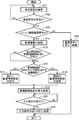
次に、被監視者監視システムMSにおける、携帯端末装置TAにおける画面表示の動作について、説明する。図5は、実施形態の被監視者監視システムの携帯端末装置における、検知結果の通報に関する動作を示すフローチャートである。図6は、実施形態の被監視者監視システムの携帯端末装置における、表示画面記憶部の第1の記憶態様を説明するための図である。図7は、実施形態の被監視者監視システムにおける、監視情報画面の消去に関する動作を示すフローチャートである。図7(A)は、管理サーバ装置SVにおける監視情報画面の消去に関する動作を示し、図7(B)は、携帯端末装置TAにおける監視情報画面の消去に関する動作を示す。図8は、実施形態の被監視者監視システムにおける携帯端末装置に表示される待受け画面の一例を示す図である。図9は、実施形態の被監視者監視システムにおける携帯端末装置に表示される、静止画を表示した監視情報画面の一例を示す図である。図10は、実施形態の被監視者監視システムにおける携帯端末装置に表示される、動画を表示した監視情報画面の一例を示す図である。図11は、互いに異なる2以上のセンサ装置から通報を受けた、前記携帯端末装置に表示される監視情報画面の一例を示す図である。
Next, the screen display operation in the portable terminal device TA in the monitored person monitoring system MS will be described. FIG. 5 is a flowchart illustrating an operation related to notification of a detection result in the mobile terminal device of the monitored person monitoring system according to the embodiment. FIG. 6 is a diagram for explaining a first storage mode of the display screen storage unit in the portable terminal device of the monitored person monitoring system according to the embodiment. FIG. 7 is a flowchart illustrating an operation related to deletion of the monitoring information screen in the monitored person monitoring system according to the embodiment. FIG. 7A shows an operation related to the deletion of the monitoring information screen in the management server device SV, and FIG. 7B shows an operation related to the deletion of the monitoring information screen in the mobile terminal device TA. FIG. 8 is a diagram illustrating an example of a standby screen displayed on the mobile terminal device in the monitored person monitoring system according to the embodiment. FIG. 9 is a diagram illustrating an example of a monitoring information screen displaying a still image displayed on the mobile terminal device in the monitored person monitoring system according to the embodiment. FIG. 10 is a diagram illustrating an example of a monitoring information screen displaying a moving image displayed on the mobile terminal device in the monitored person monitoring system according to the embodiment. FIG. 11 is a diagram illustrating an example of a monitoring information screen displayed on the mobile terminal device that has received a report from two or more different sensor devices.
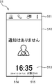
図5において、携帯端末装置TAは、電源が投入されて起動し、例えば看護師や介護士等の監視者(ユーザ)によるログイン操作を受け付け、TA監視処理部322の表示処理部3221によって、自機宛の通信信号を待ち受ける待受け画面をTA表示部36に表示する(S11)。この待受け画面51は、例えば、図8に示すように、メニューバーを表示するメニューバー領域511と、待ち受け中であることを表すメッセージ(例えば「通知はありません」)およびアイコンを表示する待受けメイン領域512と、現在時刻を表示する時刻領域513と、今日の年月日曜日を表示する年月日曜日領域514と、今、当該携帯端末装置TAにログインしているユーザ名を表示するユーザ名領域515とを備える。
In FIG. 5, the mobile terminal device TA is activated when the power is turned on, accepts a login operation by a monitor (user) such as a nurse or a caregiver, and is automatically performed by the display processing unit 3221 of the TA monitoring processing unit 322. A standby screen for waiting for a communication signal addressed to the device is displayed on the TA display unit 36 (S11). For example, as shown in FIG. 8, the standby screen 51 includes a menu bar area 511 for displaying a menu bar, and a standby main area for displaying a message indicating standby (for example, “no notification”) and an icon. 512, a time area 513 for displaying the current time, a year / month / sunday area 514 for displaying the current year / month / sunday, and a user name area 515 for displaying the name of the user who is currently logged in to the portable terminal device TA. Is provided.
次に、携帯端末装置TAは、TA制御部321によって、TA通信IF部31で自機宛の通信信号を受信したか否かを判断する(S12)。この判断の結果、自機宛の通信信号を受信していない場合(No)には、携帯端末装置TAは、処理をS11に戻し、前記判断の結果、自機宛の通信信号を受信している場合(Yes)には、携帯端末装置TAは、次の処理S13を実行する。
Next, the portable terminal device TA determines whether or not the TA control unit 321 has received a communication signal addressed to itself by the TA communication IF unit 31 (S12). As a result of this determination, if the communication signal addressed to the own device is not received (No), the portable terminal device TA returns the process to S11, and as a result of the determination, receives the communication signal addressed to the own device. If yes (Yes), the portable terminal device TA executes the next process S13.
この処理S13では、自機宛の通信信号を受信すると、携帯端末装置TAは、TA監視処理部322によって、この受信した通信信号がイベント通報通信信号であるか否かを判定する。この判定の結果、前記受信した通信信号がイベント通報通信信号ではない場合(No)には、携帯端末装置TAは、TA制御処理部32によって、前記受信した通信信号に応じた適宜な処理(一例では、後述の図7(B)に示す各処理)を実行し(S26)、この画面表示の動作を終了する。一方、前記判定の結果、前記受信した通信信号がイベント通報通信信号である場合(Yes)には、携帯端末装置TAは、TA監視処理部322によって、前記受信したイベント通報通信信号に収容されているセンサID、イベント種別(前記検知行動情報による行動の種類(本実施形態では起床、離床、転倒、転落)、イベント時刻(または受信時刻)、静止画の画像データ(またはそのファイル名)および動画を取得するための通信アドレスを、監視情報テーブルMT-TAに登録することで、これらを互いに対応付けてTA監視情報記憶部332に記憶し(S14)、次の処理S15を実行する。なお、監視情報テーブルMT-TAに前記各情報を登録する際に、TA監視処理部322は、その対応フィールド56-TAにはデフォルトのフラグ「0」を登録する。
In this process S13, when receiving a communication signal addressed to itself, the portable terminal device TA determines whether or not the received communication signal is an event notification communication signal by the TA monitoring processing unit 322. If the received communication signal is not an event notification communication signal as a result of this determination (No), the mobile terminal device TA uses the TA control processing unit 32 to perform appropriate processing (an example) according to the received communication signal. Then, each process shown in FIG. 7B described later is executed (S26), and this screen display operation is terminated. On the other hand, if the received communication signal is an event notification communication signal as a result of the determination (Yes), the mobile terminal device TA is accommodated in the received event notification communication signal by the TA monitoring processing unit 322. Sensor ID, event type (type of action based on the detected action information (wake-up, get-off, fall, fall) in this embodiment), event time (or reception time), still image data (or file name) and video Is registered in the monitoring information table MT-TA so that they are associated with each other and stored in the TA monitoring information storage unit 332 (S14), and the next process S15 is executed. When registering each piece of information in the monitoring information table MT-TA, the TA monitoring processing unit 322 sets a default in the corresponding field 56-TA. To the registration of the flag "0".
この処理S15では、携帯端末装置TAは、TA監視処理部322によって、前記受信したイベント通報通信信号に収容された監視情報にかかる被監視者Ob-Bと異なる被監視者Ob-Aにかかる監視情報を表示する他の監視情報画面52-A(監視情報画面52a(52b))が既に存在するか否かを判定し、次の処理S16を実行する。なお、この処理S15の判定結果は、後述の処理S17、処理S18および処理S19それぞれで用いられる。より具体的には、TA監視処理部322は、前記受信したイベント通報通信信号に収容されているセンサIDと異なるセンサIDが、対応フィールド56-TAにフラグ「0」を登録するレコードのセンサIDフィールド51-TAに登録されているか否かを判定することによって、他の監視情報画面52-Aが既に存在するか否かを判定する。この判定の結果、前記受信したイベント通報通信信号に収容されているセンサIDと異なるセンサIDが、対応フィールド56-TAにフラグ「0」を登録するレコードのセンサIDフィールド51-TAに登録されていない場合、異なるセンサIDの監視情報通画面52-Aが存在していないと判定し(No)、携帯端末装置TAは、次の処理S16を実行し、一方、前記判定の結果、前記受信したイベント通報通信信号に収容されているセンサIDと異なるセンサIDが、対応フィールド56-TAにフラグ「0」を登録するレコードのセンサIDフィールド51-TAに登録されている場合、異なるセンサIDの監視情報画面52-Aが既に存在していると判定し(Yes)、携帯端末装置TAは、次の処理S16を実行する。
In this process S15, the mobile terminal device TA uses the TA monitoring processor 322 to monitor a monitored person Ob-A different from the monitored person Ob-B related to the monitoring information contained in the received event notification communication signal. It is determined whether another monitoring information screen 52-A (monitoring information screen 52a (52b)) for displaying information already exists, and the next process S16 is executed. Note that the determination result of the process S15 is used in each of a process S17, a process S18, and a process S19 described later. More specifically, the TA monitoring processing unit 322 has a sensor ID different from the sensor ID contained in the received event notification communication signal, and the sensor ID of the record in which the flag “0” is registered in the corresponding field 56-TA. By determining whether or not the field 51-TA is registered, it is determined whether or not another monitoring information screen 52-A already exists. As a result of this determination, a sensor ID different from the sensor ID accommodated in the received event notification communication signal is registered in the sensor ID field 51-TA of the record in which the flag “0” is registered in the corresponding field 56-TA. If not, it is determined that there is no monitoring information screen 52-A with a different sensor ID (No), and the portable terminal device TA executes the next process S16, while the result of the determination is that the received When a sensor ID different from the sensor ID accommodated in the event notification communication signal is registered in the sensor ID field 51-TA of the record in which the flag “0” is registered in the corresponding field 56-TA, the different sensor IDs are monitored. It is determined that the information screen 52-A already exists (Yes), and the mobile terminal device TA executes the next process S16.
この処理S16では、携帯端末装置TAは、TA監視処理部322によって、前記受信したイベント通報通信信号に収容されている監視情報が監視情報画面52a(52b)の存在しているセンサ装置SUに関する監視情報であるか否かを判定する。より具体的には、TA監視処理部322は、前記受信したイベント通報通信信号に収容されているセンサIDと同じセンサIDを収容したイベント通報通信信号を、前記受信したイベント通報通信信号より前に(過去に)既に受信し、この既に受信したイベント通報通信信号の監視情報画面52a(52b)が表示のために作成されている否かを判定する。より詳しくは、TA監視処理部322は、前記受信したイベント通報通信信号に収容されているセンサIDと同じセンサIDが、対応フィールド56-TAにフラグ「0」を登録するレコードのセンサIDフィールド51-TAに登録されているか否かを判定することによって、前記既に受信し、この既に受信したイベント通報通信信号の監視情報画面52a(52b)が表示のために作成されている否かを判定する。この判定の結果、前記受信したイベント通報通信信号に収容されているセンサIDと同じセンサIDが、対応フィールド56-TAにフラグ「0」を登録するレコードのセンサIDフィールド51-TAに登録されていない場合、同じセンサIDのイベント通報通信信号を既に受信していないと判定し(No)、携帯端末装置TAは、処理S17を実行し、一方、前記判定の結果、前記受信したイベント通報通信信号に収容されているセンサIDと同じセンサIDが、対応フィールド56-TAにフラグ「0」を登録するレコードのセンサIDフィールド51-TAに登録されている場合、同じセンサIDのイベント通報通信信号を既に受信していると判定し(Yes)、携帯端末装置TAは、処理S18を実行する。
In this process S16, the mobile terminal device TA monitors the sensor device SU in which the monitoring information contained in the received event notification communication signal is present on the monitoring information screen 52a (52b) by the TA monitoring processing unit 322. It is determined whether it is information. More specifically, the TA monitoring processor 322 sends an event report communication signal containing the same sensor ID as the sensor ID contained in the received event report communication signal before the received event report communication signal. It is determined whether or not the monitoring information screen 52a (52b) of the already received event notification communication signal has been created for display. More specifically, the TA monitoring processing unit 322 records the sensor ID field 51 of the record in which the same sensor ID as that contained in the received event notification communication signal registers the flag “0” in the corresponding field 56-TA. -Determine whether or not the monitoring information screen 52a (52b) of the already received event notification communication signal has been created for display by determining whether or not it is registered in the TA . As a result of this determination, the same sensor ID as that contained in the received event notification communication signal is registered in the sensor ID field 51-TA of the record in which the flag “0” is registered in the corresponding field 56-TA. If not, it is determined that the event notification communication signal of the same sensor ID has not been received (No), and the mobile terminal device TA executes the process S17. On the other hand, as a result of the determination, the received event notification communication signal When the same sensor ID as that stored in the sensor ID is registered in the sensor ID field 51-TA of the record in which the flag “0” is registered in the corresponding field 56-TA, an event notification communication signal of the same sensor ID is sent. It determines with having already received (Yes) and portable terminal device TA performs process S18.
この処理S17では、携帯端末装置TAは、TA監視処理部322の表示処理部3221によって、前記受信したイベント通報通信信号に収容されている各情報(各データ)に従った監視情報画面52aを新たに表示画面記憶部331に形成して記憶する。
In this process S17, the mobile terminal device TA newly displays the monitoring information screen 52a according to each information (each data) contained in the received event notification communication signal by the display processing unit 3221 of the TA monitoring processing unit 322. Is formed and stored in the display screen storage unit 331.
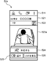
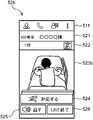
この監視情報画面52aは、被監視者Obの監視に関する前記監視情報を表示するための画面である。前記監視情報画面52aは、例えば、図9に示すように、メニューバー領域511と、センサIDのセンサ装置SUの配設場所および前記センサIDの前記センサ装置SUによって監視される被監視者Obの名前を表示する被監視者名領域521と、イベント時刻(または受信時刻)からの経過時間および前記検知行動情報によって表される検知結果を象徴的に表すアイコンを表示するアイコン領域522と、前記センサIDの前記センサ装置SUによって撮像された画像(ここでは静止画)を表示する画像領域523aと、「対応する」ボタン524と、「話す」ボタン525と、「LIVEを見る」ボタン526とを備える。「対応する」ボタン524は、前記センサIDの前記センサ装置SUによって監視される被監視者Obに対する例えば救命、看護、介護および介助等の前記対応(対処、応対)を実行する意思(対応意思、対処意思、応対意思)が当該携帯端末装置TAのユーザにあることを当該携帯端末装置TAに入力するためのボタンである。「話す」ボタン525は、音声通話を要求するためのボタンであって、前記センサIDの前記センサ装置SUと当該携帯端末装置TAとをネットワークNWを介して通話可能に接続する指示を入力するためのボタンである。「LIVEを見る」ボタン526は、ライブでの動画を要求するためのボタンであって、前記センサIDの前記センサ装置SUによって撮像される動画を表示させる指示を入力するためのボタンである。
The monitoring information screen 52a is a screen for displaying the monitoring information related to monitoring of the monitored person Ob. As shown in FIG. 9, for example, the monitoring information screen 52a includes a menu bar area 511, the location of the sensor ID sensor device SU, and the monitored person Ob monitored by the sensor ID SU of the sensor ID. Monitored person name area 521 for displaying a name, icon area 522 for displaying an icon symbolically representing an elapsed time from an event time (or reception time) and a detection result represented by the detected behavior information, and the sensor An image area 523a for displaying an image (here, a still image) captured by the ID sensor device SU, a “corresponding” button 524, a “speak” button 525, and a “view LIVE” button 526 are provided. . The “corresponding” button 524 is an intention (responding intention, It is a button for inputting to the mobile terminal device TA that the user of the mobile terminal device TA has a handling intention and a willingness to respond. The “speak” button 525 is a button for requesting a voice call, and is used to input an instruction to connect the sensor device SU of the sensor ID and the mobile terminal device TA via the network NW. It is a button. The “LIVE” button 526 is a button for requesting a live video, and is a button for inputting an instruction to display a video captured by the sensor device SU of the sensor ID.
前記受信したイベント通報通信信号に収容されている各情報に従った監視情報画面52aを作成するために、表示処理部3221は、前記受信したイベント通報通信信号に収容されているセンサIDに対応する配設場所および被監視者名をTAセンサ装置情報記憶部333から前記センサIDを検索キーとして検索し、前記受信したイベント通報通信信号に収容されているイベント時刻(またはその受信時刻)からの経過時間を求め、前記受信したイベント通報通信信号に収容されている前記検知行動情報によって表される検知結果に対応するアイコンをTA記憶部33から前記検知結果を検索キーとして検索する。なお、各検知結果(本実施形態では起床、離床、転倒および転落)に対応する各アイコンは、各検知結果に対応付けられてTA記憶部33に予め記憶される。そして、表示処理部3221は、メニューバーをメニューバー領域511に表示し、前記検索した配設場所および被監視者名を被監視者名領域521に表示し、前記求めた経過時間および前記検索したアイコンをアイコン領域522に表示し、前記受信したイベント通報通信信号に収容されている画像(静止画)を画像領域523aに表示し、「対応する」ボタン524、「話す」ボタン525、および、「LIVEを見る」ボタン526を表示することで監視情報画面52aを表示画面記憶部331に形成して記憶する。
In order to create the monitoring information screen 52a according to each information accommodated in the received event notification communication signal, the display processing unit 3221 corresponds to the sensor ID accommodated in the received event notification communication signal. The location and the name of the monitored person are searched from the TA sensor device information storage unit 333 using the sensor ID as a search key, and the elapsed time from the event time (or the reception time) contained in the received event notification communication signal Time is obtained, and an icon corresponding to the detection result represented by the detection behavior information contained in the received event notification communication signal is searched from the TA storage unit 33 using the detection result as a search key. In addition, each icon corresponding to each detection result (in this embodiment, getting up, getting out of bed, falling, and falling) is stored in advance in the TA storage unit 33 in association with each detection result. Then, the display processing unit 3221 displays a menu bar in the menu bar area 511, displays the searched arrangement location and monitored person name in the monitored person name area 521, and calculates the obtained elapsed time and the searched item. An icon is displayed in the icon area 522, an image (still image) contained in the received event notification communication signal is displayed in the image area 523a, a “corresponding” button 524, a “speak” button 525, and “ By displaying a “LIVE” button 526, the monitoring information screen 52a is formed and stored in the display screen storage unit 331.
そして、このように新たな監視情報画面52aを形成すると、表示処理部3221は、前記処理S15における判定の結果、異なるセンサIDの監視情報画面等52-Aが既に存在している場合には、前記新たに形成した監視情報画面52a-Bと前記既に存在している監視情報画面等52-Aとを前記所定の序列で関連付けて表示画面記憶部331に記憶する。より具体的には、表示処理部3221は、前記新たに形成した監視情報画面52a-Bを、前記既に存在している監視情報画面等52-Aに対し、TA表示部36に表示された場合の上下方向に時系列に連結してプレーンに形成する。
When the new monitoring information screen 52a is formed in this way, the display processing unit 3221 determines that the monitoring information screen 52-A with a different sensor ID already exists as a result of the determination in the processing S15. The newly formed monitoring information screen 52a-B and the already existing monitoring information screen 52-A are associated with each other in the predetermined order and stored in the display screen storage unit 331. More specifically, the display processing unit 3221 displays the newly formed monitoring information screen 52a-B on the TA display unit 36 with respect to the already existing monitoring information screen 52-A. Are connected in chronological order to form a plane.
図5に戻って、処理S18では、携帯端末装置TAは、TA監視処理部322の表示処理部3221によって、前記受信したイベント通報通信信号に収容されている各情報(各データ)に従って監視情報画面52a(52a-B)を更新し、表示画面記憶部331に形成して記憶する。
Returning to FIG. 5, in process S <b> 18, the mobile terminal device TA displays a monitoring information screen according to each information (each data) accommodated in the received event notification communication signal by the display processing unit 3221 of the TA monitoring processing unit 322. 52a (52a-B) is updated and formed and stored in the display screen storage unit 331.
前記受信したイベント通報通信信号に収容されている各情報に従って監視情報画面52a-Bを更新するために、表示処理部3221は、前記受信したイベント通報通信信号に収容されているイベント時刻(または受信時刻)からの経過時間を求め、前記受信したイベント通報通信信号に収容されている前記検知行動情報によって表される検知結果に対応するアイコンをTA記憶部33から前記検知結果を検索キーとして検索する。そして、表示処理部3221は、既に存在している監視情報画面52a-Bに対し、前記求めた経過時間および前記検索したアイコンをアイコン領域522に表示し、前記受信したイベント通報通信信号に収容されている画像(静止画)を画像領域523aに表示することで監視情報画面52a-Bを更新し、表示画面記憶部331に記憶(形成)する。ここで、アイコン領域522には、既に受信していたイベント通報通信信号に収容された検知結果に応じてアイコンが表示されているので、今般の前記検索したアイコンは、この既に表示されているアイコンに対して時系列に並べられてアイコン領域522に表示される。例えば、被監視者Obの判定結果「起床」が報知された後に、その判定結果「離床」が報知された場合、図9に示す、被監視者Obの検知結果「起床」を表すアイコンがアイコン領域522に表示されている監視情報画面52aは、被監視者Obの検知結果「離床」を表すアイコンが前記検知結果「起床」を表すアイコンに対する紙面左隣に並べてアイコン領域522に表示されて更新される。
In order to update the monitoring information screen 52a-B according to each information accommodated in the received event notification communication signal, the display processing unit 3221 uses the event time (or reception) received in the received event notification communication signal. Elapsed time from (time) and search for an icon corresponding to the detection result represented by the detection behavior information contained in the received event notification communication signal from the TA storage unit 33 using the detection result as a search key. . Then, the display processing unit 3221 displays the obtained elapsed time and the searched icon in the icon area 522 on the existing monitoring information screen 52a-B, and is stored in the received event notification communication signal. The monitoring information screen 52a-B is updated by displaying the current image (still image) in the image area 523a and stored (formed) in the display screen storage unit 331. Here, since an icon is displayed in the icon area 522 according to the detection result accommodated in the already received event notification communication signal, the searched icon is the icon that has already been displayed. Are displayed in the icon area 522 in time series. For example, when the determination result “getting up” is notified after the determination result “wake-up” of the monitored person Ob is notified, an icon representing the detection result “wake-up” of the monitored person Ob shown in FIG. The monitoring information screen 52a displayed in the area 522 is updated by displaying the icon representing the detection result “getting out” of the monitored person Ob next to the icon representing the detection result “getting up” in the icon area 522. Is done.
そして、このように監視情報画面52a-Bを更新して形成すると、処理S17と同様に、表示処理部3221は、前記処理S15における判定の結果、異なるセンサIDの監視情報画面52-Aが既に存在している場合には、前記更新して形成した監視情報画面52a-Bと前記既に存在している監視情報画面52-Aとを前記所定の序列で関連付けて表示画面記憶部331に記憶する。より具体的には、表示処理部3221は、前記更新して形成した監視情報画面52a-Bを、前記既に存在している監視情報画面52-Aに対し、TA表示部36に表示された場合の上下方向に時系列に連結してプレーンに形成する。なお、表示処理部3221は、既存の時系列の関連付け(時系列の連結)を維持してこれらを時系列に関連付けて良く、また、前記受信したイベント通報通信信号に基づいて新たな時系列で関連付けてこれらを再編しても良い。
When the monitoring information screen 52a-B is updated and formed in this way, the display processing unit 3221, as a result of the determination in the processing S15, already has the monitoring information screen 52-A of a different sensor ID as in the processing S17. If it exists, the updated monitoring information screen 52a-B and the existing monitoring information screen 52-A are associated with each other in the predetermined order and stored in the display screen storage unit 331. . More specifically, the display processing unit 3221 displays the updated monitoring information screen 52a-B on the TA display unit 36 with respect to the already existing monitoring information screen 52-A. Are connected in chronological order to form a plane. The display processing unit 3221 may maintain existing time-series associations (time-series connection) to associate them with the time series, and may display a new time series based on the received event notification communication signal. These may be associated and reorganized.
上述の処理S17の次に、または、処理S18の次に、表示処理部3221は、監視情報画面52aを表示する所定の処理を実行する(S19)。より具体的には、表示処理部3221は、前記処理S15における判定の結果、異なるセンサIDの監視情報画面52-Aが既に存在していない場合(すなわち、処理S17または処理S18による1つの監視情報画面52aが存在する場合)には、処理S17で新たに作成した新規の監視情報画面52aを、または、処理S18で更新した更新の監視情報画面52aを、TA表示部36に表示する。一方、表示処理部3221は、前記処理S15における判定の結果、異なるセンサIDの監視情報画面52-Aが既に存在している場合(すなわち、互いに異なる複数の被監視者Obそれぞれに関する各監視情報を表す複数の監視情報画面52aが存在する場合)には、TA表示部36に表示されている既存の表示内容を維持し、この既存の表示内容に前記新着監視情報表示532をさらに表示する。
After the above-described process S17 or after the process S18, the display processing unit 3221 executes a predetermined process for displaying the monitoring information screen 52a (S19). More specifically, the display processing unit 3221 determines that the monitoring information screen 52-A with a different sensor ID does not already exist as a result of the determination in the processing S15 (that is, one monitoring information by the processing S17 or the processing S18). When the screen 52a exists), the new monitoring information screen 52a newly created in the process S17 or the updated monitoring information screen 52a updated in the process S18 is displayed on the TA display unit 36. On the other hand, the display processing unit 3221 displays the monitoring information regarding each of a plurality of different monitored persons Ob when different monitoring information screens 52-A with different sensor IDs already exist as a result of the determination in the processing S15. In the case where there are a plurality of monitoring information screens 52a to be displayed), the existing display contents displayed on the TA display unit 36 are maintained, and the new arrival monitoring information display 532 is further displayed on the existing display contents.
一例では、図6において、複数の監視情報画面52-P1が存在する場合に、時刻T0において、新たにイベント通報通信信号を受信すると、携帯端末装置TAは、処理S13、処理S14、処理S15、処理S16および処理S17を実行することで、この新たに受信したイベント通報通信信号に対応した監視情報画面52a-T0を形成し、この新たに形成した監視情報画面52a-T0を、前記既に存在している監視情報画面52-Pに対しTA表示部36に表示された場合の上下方向に時系列に連結してプレーンPLaを形成し、表示画面記憶部331に記憶する。前記複数の監視情報画面52-P1は、過去の時刻Tkにかかる監視情報画面52a-Tkを含む複数の監視情報画面52-P0に対し過去の時刻T4にかかる監視情報画面52a-T4をTA表示部36に表示された場合の上下方向に時系列に連結し、この監視情報画面52a-T4に対し過去の時刻T3にかかる監視情報画面52a-T3をTA表示部36に表示された場合の上下方向に時系列に連結し、この監視情報画面52a-T3に対し過去の時刻T2にかかる監視情報画面52a-T2をTA表示部36に表示された場合の上下方向に時系列に連結し、そして、この監視情報画面52a-T2に対し過去の時刻T1にかかる監視情報画面52a-T1をTA表示部36に表示された場合の上下方向に時系列に連結してプレーンを形成することで構成されている。なお、過去<時刻Tk<・・・<時刻T4<時刻T3<時刻T2<時刻T1<時刻T0<現在の時系列である。そして、携帯端末装置TAは、処理S19を実行することで、TA表示部36に表示されている既存の表示内容を維持し、この既存の表示内容に前記新着監視情報表示532をさらに表示する。図6に示す例では、過去の時刻T4にかかる監視情報画面52a-T4がTA表示部36に表示されており、処理S19では、この監視情報画面52a-T4の表示が維持され、この監視情報画面52a-T4に前記新着監視情報表示532がさらに表示される。
For example, in FIG. 6, when a plurality of monitoring information screens 52-P1 exist, when a new event notification communication signal is received at time T0, the mobile terminal device TA performs processing S13, processing S14, processing S15, By executing the processing S16 and S17, the monitoring information screen 52a-T0 corresponding to the newly received event notification communication signal is formed, and the newly formed monitoring information screen 52a-T0 already exists. A plane PLa is formed by connecting the monitoring information screen 52 -P in time series in the vertical direction when displayed on the TA display unit 36 with respect to the monitoring information screen 52 -P, and is stored in the display screen storage unit 331. The plurality of monitoring information screens 52-P1 display the TAs of the monitoring information screens 52a-T4 related to the past time T4 with respect to the plurality of monitoring information screens 52-P0 including the monitoring information screens 52a-Tk related to the past time Tk. When the monitor information screens 52a-T3 are displayed on the TA display unit 36, the monitor information screens 52a-T3 of the past time T3 are connected to the monitor information screens 52a-T4 in time series. The monitoring information screens 52a-T2 related to the past time T2 are connected to the monitoring information screens 52a-T3 in the time series in the vertical direction when displayed on the TA display unit 36, and The monitoring information screen 52a-T1 at the past time T1 is connected to the monitoring information screen 52a-T2 in time series in the vertical direction when the TA display unit 36 displays the plane. It is constructed by forming. Note that past <time Tk <... <Time T4 <time T3 <time T2 <time T1 <time T0 <current time series. And portable terminal device TA maintains the existing display content currently displayed on TA display part 36 by performing process S19, and also displays the new arrivals monitoring information display 532 on this existing display content. In the example shown in FIG. 6, the monitoring information screens 52a-T4 for the past time T4 are displayed on the TA display unit 36, and in the process S19, the display of the monitoring information screens 52a-T4 is maintained. The new arrival monitoring information display 532 is further displayed on the screen 52a-T4.
次に、携帯端末装置TAは、TA制御処理部32によって、TA入力部35およびTA表示部36を備えて成るタッチパネルで入力操作を受け付けたか否かを判定する(S20)。この判定の結果、入力操作を受け付けていない場合(No)には、携帯端末装置TAは、処理を処理S21に戻し、一方、前記判定の結果、入力操作を受け付けている場合には、携帯端末装置TAは、次の処理S21を実行する。
Next, the portable terminal device TA determines whether or not an input operation is accepted by the TA control processing unit 32 using a touch panel including the TA input unit 35 and the TA display unit 36 (S20). If the input operation is not accepted as a result of this determination (No), the mobile terminal device TA returns the process to step S21. On the other hand, if the input operation is accepted as a result of the determination, the mobile terminal TA The apparatus TA performs the following process S21.
この処理S21では、携帯端末装置TAは、TA制御処理部32によって、入力操作の内容に応じた適宜な処理を実行し、この画面表示の動作を終了する。
In this process S21, the portable terminal device TA performs an appropriate process according to the content of the input operation by the TA control processing unit 32, and ends the screen display operation.
例えば、携帯端末装置TAは、TA制御処理部32によって、「LIVEを見る」ボタン526の入力操作を受け付けると、TAストリーミング処理部324によって、現在、TA表示部36に表示している被監視者Obを監視するセンサ装置SUへ、ライブでの動画の配信を要求する旨等の情報を収容した通信信号(動画配信要求通信信号)を送信し、これに応じたセンサ装置SUとネットワークNWを介して動画のダウンロード可能に接続し、前記センサ装置SUからライブでの動画の配信を受け、この配信を受けた動画をストリーミング再生でTA表示部36に表示する。このライブでの動画を表示する監視情報画面52bは、例えば、図10に示すように、図9に示す監視情報画面52aにおいて、静止画を表示する画像領域523aに代え動画を表示する画像領域523bを備え、そして、「LIVEを見る」ボタン526に代え「LIVE終了」ボタン528を備えて構成される。「LIVE終了」ボタン528は、動画の終了を要求するためのボタンであって、前記センサIDの前記センサ装置SUによって撮像される動画の配信を終了(停止)させ表示を終了(停止)させる指示を入力するためのボタンである。
For example, when the mobile terminal device TA accepts an input operation of the “watch live” button 526 by the TA control processing unit 32, the monitored person currently displayed on the TA display unit 36 by the TA streaming processing unit 324. A communication signal (moving image distribution request communication signal) containing information such as a request for live video distribution is transmitted to the sensor device SU that monitors Ob, and the sensor device SU and the network NW corresponding thereto are transmitted. Then, the video is connected so that the video can be downloaded, the live video is distributed from the sensor device SU, and the video that has received the distribution is displayed on the TA display unit 36 by streaming reproduction. For example, as shown in FIG. 10, the monitoring information screen 52 b that displays the live moving image is an image region 523 b that displays a moving image instead of the image region 523 a that displays a still image in the monitoring information screen 52 a illustrated in FIG. 9. In addition, a “LIVE END” button 528 is provided instead of the “VIEW LIVE” button 526. The “live end” button 528 is a button for requesting the end of the moving image, and is an instruction to end (stop) the distribution of the moving image captured by the sensor device SU of the sensor ID and end (stop) the display. It is a button for inputting.
また例えば、携帯端末装置TAは、TA制御処理部32によって、「LIVE終了」ボタン528の入力操作を受け付けると、TAストリーミング処理部324によって、現在、TA表示部36に表示している被監視者Obを監視するセンサ装置SUへ、動画配信の終了を要求する旨等の情報を収容した通信信号(動画配信終了通信信号)を送信し、静止画を表示する監視情報画面52aをTA表示部36に表示する。
Further, for example, when the mobile terminal device TA receives an input operation of the “live end” button 528 by the TA control processing unit 32, the monitored person currently displayed on the TA display unit 36 by the TA streaming processing unit 324. The TA display unit 36 displays a monitoring information screen 52a that displays a still image by transmitting a communication signal (moving image distribution end communication signal) containing information such as requesting the end of moving image distribution to the sensor device SU that monitors Ob. To display.
また例えば、携帯端末装置TAは、TA制御処理部32によって、「話す」ボタン525の入力操作を受け付けると、TA音声通話処理部323によって、TA表示部36に表示している被監視者Obを監視するセンサ装置SUへ、音声通話を要求する旨等の情報を収容した通信信号(通話要求通信信号)を送信し、これに応じたセンサ装置SUとネットワークNWを介して音声通話可能に接続する。これによって携帯端末装置TAとセンサ装置SUとの間で音声通話が可能となる。
Further, for example, when the mobile terminal device TA receives an input operation of the “speak” button 525 by the TA control processing unit 32, the TA voice call processing unit 323 displays the monitored subject Ob displayed on the TA display unit 36. A communication signal (call request communication signal) containing information such as requesting a voice call is transmitted to the monitoring sensor device SU, and the corresponding sensor device SU is connected to the sensor device SU via the network NW so as to be able to make a voice call. . As a result, a voice call can be made between the mobile terminal device TA and the sensor device SU.
また例えば、携帯端末装置TAは、TA制御処理部32によって、音声通話の終了の指示を入力するためのボタンである図略の「終了」ボタンの入力操作を受け付けると、TA音声通話処理部323によって、TA表示部36に表示している被監視者Obを監視するセンサ装置SUへ、音声通話の終了を要求する旨等の情報を収容した通信信号(通話終了通信信号)を送信する。
In addition, for example, when the mobile terminal device TA receives an input operation of an “end” button (not shown), which is a button for inputting an instruction to end a voice call, by the TA control processing unit 32, the TA voice call processing unit 323. Thus, a communication signal (call end communication signal) containing information such as a request to end the voice call is transmitted to the sensor device SU that monitors the monitored person Ob displayed on the TA display unit 36.
また例えば、携帯端末装置TAは、TA制御処理部32によって、「対応する」ボタン524の入力操作を受け付けると(すなわち、前記対応意思を受け付けると)、現在、TA表示部36に表示している被監視者Obの監視情報に対応するセンサIDをセンサIDフィールド51-TAに登録しているレコードにおける、対応フィールド56-TAにフラグ「1」を登録し、表示処理部3221によって、この被監視者Obの監視情報をTA表示部36に表示しない。より具体的には、表示処理部3221は、この被監視者Obの監視情報を表示する監視情報画面52aを表示画面記憶部331から消去することで、この被監視者Obの監視情報をTA表示部36に表示しない。より詳しくは、表示処理部3221は、この被監視者Obの監視情報を表示する監視情報画面52aのみが存在する場合、この監視情報画面52aを表示画面記憶部331から消去し、待受け画面51をTA表示部36に表示する。一方、表示処理部3221は、複数の監視情報画面52aが存在する場合、この監視情報画面52aを表示画面記憶部331から消去し、残余の監視情報画面52aで、TA表示部36に表示された場合の上下方向に時系列に連結することでプレーンに形成して表示画面記憶部331し、所定の監視情報画面52aをTA表示部36に表示する。例えば、この消去した監視情報画面52aに時間的に直近する監視情報画面52a(この消去した監視情報画面52aを形成した直後に受信したイベント通報通信信号にかかる監視情報画面52a、または、消去した監視情報画面52aを形成する直前に受信したイベント通報通信信号にかかる監視情報画面52a)がTA表示部36に表示される。また例えば、残余の監視情報画面52aの中で最も過去に受信したイベント通報通信信号にかかる監視情報画面52aがTA表示部36に表示される。また例えば、残余の監視情報画面52aの中で最新に受信したイベント通報通信信号にかかる監視情報画面52aがTA表示部36に表示される。そして、表示処理部3221は、当該携帯端末装置TAにログインしている監視者(ユーザ)が、この消去した監視情報画面52aの被監視者Obに対し例えば看護等の前記対応を実行する意思(対応意思)があり、その前記対応意思を受け付けた旨を通知するための通信信号(対応通知通信信号)を、管理サーバ装置SVへ送信する。この対応通知通信信号には、前記対応意思を受け付けたことを表す情報(対応意思受付情報)、前記対応の対象を表す情報として、この消去した監視情報画面52aの監視情報に対応するセンサID、および、前記対応を実行する主体を表す情報として、当該携帯端末装置TAの端末ID等が収容される。前記端末IDは、TA記憶部33から取得される。
Also, for example, when the TA control processing unit 32 receives an input operation of the “corresponding” button 524 (that is, when the corresponding intention is received), the portable terminal device TA is currently displaying on the TA display unit 36. In the record in which the sensor ID corresponding to the monitoring information of the monitored person Ob is registered in the sensor ID field 51-TA, the flag “1” is registered in the corresponding field 56-TA. The monitoring information of the person Ob is not displayed on the TA display unit 36. More specifically, the display processing unit 3221 deletes the monitoring information screen 52a that displays the monitoring information of the monitored person Ob from the display screen storage unit 331, so that the monitoring information of the monitored person Ob is displayed as a TA. It is not displayed on the part 36. More specifically, when only the monitoring information screen 52a that displays the monitoring information of the monitored person Ob exists, the display processing unit 3221 deletes the monitoring information screen 52a from the display screen storage unit 331, and displays the standby screen 51. The information is displayed on the TA display unit 36. On the other hand, when there are a plurality of monitoring information screens 52a, the display processing unit 3221 deletes the monitoring information screen 52a from the display screen storage unit 331 and displays the remaining monitoring information screen 52a on the TA display unit 36. In this case, the display screen storage unit 331 is formed in a plane by connecting in time series in the vertical direction, and a predetermined monitoring information screen 52 a is displayed on the TA display unit 36. For example, the monitoring information screen 52a that is closest in time to the deleted monitoring information screen 52a (the monitoring information screen 52a related to the event notification communication signal received immediately after forming the deleted monitoring information screen 52a, or the deleted monitoring information screen 52a) A monitoring information screen 52 a) related to the event notification communication signal received immediately before forming the information screen 52 a is displayed on the TA display unit 36. In addition, for example, the monitoring information screen 52a related to the event notification communication signal received most recently in the remaining monitoring information screen 52a is displayed on the TA display unit 36. In addition, for example, the monitoring information screen 52 a related to the event notification communication signal received most recently in the remaining monitoring information screen 52 a is displayed on the TA display unit 36. Then, the display processing unit 3221 indicates that the monitor (user) logged in to the portable terminal device TA intends to execute the above-described response such as nursing on the monitored person Ob of the deleted monitoring information screen 52a ( A communication signal (response notification communication signal) for notifying that the response intention has been received is transmitted to the management server device SV. In the correspondence notification communication signal, information indicating that the intention to respond has been received (response intention reception information), sensor ID corresponding to the monitoring information on the deleted monitoring information screen 52a as information indicating the target of the correspondence, And the terminal ID of the said portable terminal device TA etc. are accommodated as information showing the main body which performs the said response | compatibility. The terminal ID is acquired from the TA storage unit 33.
また例えば、携帯端末装置TAは、TA制御処理部32によって、TA入力部35およびTA表示部36を備えて構成される前記タッチパネルに対し所定の方向に沿って行われる「フリック」の入力操作を受け付けると、表示処理部3221によって、フリック元に表示されている別監視情報画面表示531に対応する監視情報画面52の表示へ移行して表示する。前記「フリック」は、前記切換指示入力の一例に対応する。この別監視情報画面表示531(531a、531b)は、TA表示部36に表示されている監視情報画面52a-Aの他に監視情報画面52a-Bが存在していることを表す表示であり、例えば、本実施形態では、図11に示すように、三角マーク(△531a、▽531b)等である。例えば、TA表示部36の表示画面において、上から下へ「フリック」すると、フリック元に表示されている別監視情報画面表示531に対応する監視情報画面52a-Bの表示へ、表示中の監視情報画面等52a-Aから移行して監視情報画面52a-Bが表示される。より詳しくは、例えば、図11に示すように、複数のイベント通報通信信号が受信され、これらに対応した複数の監視情報画面52aが存在する場合において、表示処理部3221は、第1の監視情報画面52a-t2より前の時刻に関する第2の監視情報画面52a-t1がある場合には、第1の監視情報画面52a-t2と第2の監視情報画面52a-t1とを時系列に関係付けて表示画面記憶部331に記憶し、第1の監視情報画面52a-t2より後の時刻に関する第3の監視情報画面52a-t3がある場合には、第1の監視情報画面52a-t2と第3の監視情報画面52a-t3とを時系列に関係付けて表示画面記憶部331に記憶する。そして、表示処理部3221は、第1の監視情報画面52a-t2をTA表示部36に表示している際に、第2の監視情報画面52a-t1の存在を表す第1別監視情報画面表示531aを、第1の監視情報画面52a-t2における一方端(図11に示す例では上方端)に表示し、第3の監視情報画面52a-t3の存在を表す第2別監視情報画面表示531bを、第1の監視情報画面52a-t2における他方端(図11に示す例では下方端)に表示し、「フリック」の入力操作を受け付けると、フリック元に表示されている別監視情報画面表示531(531a、531b)に対応する監視情報画面52aの表示へ移行して表示する。より詳しくは、前記タッチパネルに対し下から上に向かう一方方向に沿って行われる第1フリックが行われると、表示処理部3221は、TA表示部36に表示される第1の監視情報画面52a-t2を、古い方から新しい方へ向かう順方向で切り換えるべく、第3の監視情報画面52a-t3に切り換えてTA表示部36に表示し、一方、前記一方方向の逆方向である、前記タッチパネルに対し上から下に向かう他方方向に沿って行われる第2フリックが行われると、表示処理部3221は、TA表示部36に表示される第1の監視情報画面52a-t2を、新しい方から古い方へ向かう逆方向で切り換えるべく、第2の監視情報画面52a-t1に切り換えてTA表示部36に表示する。このように本実施形態では、複数の監視情報画面52aが時系列に関係付けて表示画面記憶部331に記憶されているので、いわゆるフリック操作で、複数の検知結果を古い方から新しい方へ向かう順方向または新しい方から古い方へ向かう逆方向で順次にTA表示部36に表示できる。
In addition, for example, the mobile terminal device TA performs a “flick” input operation performed along a predetermined direction on the touch panel including the TA input unit 35 and the TA display unit 36 by the TA control processing unit 32. When accepted, the display processing unit 3221 shifts to the display of the monitoring information screen 52 corresponding to the different monitoring information screen display 531 displayed at the flick source and displays it. The “flick” corresponds to an example of the switching instruction input. This separate monitoring information screen display 531 (531a, 531b) is a display indicating that the monitoring information screen 52a-B exists in addition to the monitoring information screen 52a-A displayed on the TA display unit 36. For example, in this embodiment, as shown in FIG. 11, it is a triangle mark (Δ531a, ▽ 531b) or the like. For example, if “flick” is performed from the top to the bottom on the display screen of the TA display unit 36, the monitoring being displayed is changed to the display of the monitoring information screen 52a-B corresponding to the separate monitoring information screen display 531 displayed at the flick source. The monitoring information screen 52a-B is displayed after shifting from the information screen 52a-A. More specifically, for example, as shown in FIG. 11, when a plurality of event notification communication signals are received and there are a plurality of monitoring information screens 52a corresponding to these signals, the display processing unit 3221 displays the first monitoring information. When there is a second monitoring information screen 52a-t1 related to a time before the screen 52a-t2, the first monitoring information screen 52a-t2 and the second monitoring information screen 52a-t1 are related in time series. If there is a third monitoring information screen 52a-t3 related to a time later than the first monitoring information screen 52a-t2, the first monitoring information screen 52a-t2 and the first monitoring information screen 52a-t2 3 monitoring information screens 52a-t3 are stored in the display screen storage unit 331 in a time-series manner. The display processing unit 3221 displays the first monitoring information screen 52a-t1 indicating the presence of the second monitoring information screen 52a-t1 when the first monitoring information screen 52a-t2 is displayed on the TA display unit 36. 531a is displayed at one end (upper end in the example shown in FIG. 11) on the first monitoring information screen 52a-t2, and a second separate monitoring information screen display 531b indicating the presence of the third monitoring information screen 52a-t3 is displayed. Is displayed on the other end (lower end in the example shown in FIG. 11) on the first monitoring information screen 52a-t2, and when an input operation of “flick” is accepted, another monitoring information screen displayed on the original flick is displayed. The monitor information screen 52a corresponding to 531 (531a, 531b) is shifted to display. More specifically, when a first flick performed along one direction from the bottom to the top of the touch panel is performed, the display processing unit 3221 displays the first monitoring information screen 52a- displayed on the TA display unit 36. In order to switch t2 in the forward direction from the oldest to the newest, it is switched to the third monitoring information screen 52a-t3 and displayed on the TA display unit 36, while on the touch panel, which is the reverse direction of the one direction. When the second flick performed along the other direction from the top to the bottom is performed, the display processing unit 3221 displays the first monitoring information screen 52a-t2 displayed on the TA display unit 36 from the newest to the oldest. In order to switch in the reverse direction, the display is switched to the second monitoring information screen 52a-t1 and displayed on the TA display unit 36. Thus, in this embodiment, since the plurality of monitoring information screens 52a are related to each other in time series and stored in the display screen storage unit 331, a plurality of detection results are moved from the oldest to the newer by a so-called flick operation. The TA display unit 36 can sequentially display in the forward direction or the reverse direction from the newer to the older.
また、一例では、上述した図6に示す場合では、新着監視情報表示532を含む過去の監視情報画面52a-T4が携帯端末装置TAのTA表示部36に表示されている場合に、この新着監視情報表示532にかかる最新の監視情報画面52a-T0を表示すべく、前記タッチパネルに対し下から上に向かう一方方向に沿って行われる第1フリックが行われる。この第1フリックが行われると、既表示の過去の監視情報画面52a-T4から、過去の監視情報画面52a-T3、過去の監視情報画面52a-T2および過去の監視情報画面52a-T1それぞれに、古い方から新しい方へ向かう順方向で順次に切り換えられ、その後に、最新の監視情報画面52a-T0がTA表示部36に表示され、そして、新着監視情報表示532がTA表示部36から消去される。このように既表示の過去の監視情報画面52a-T4から最新の監視情報画面52a-T0までの間において、既に受信している複数のイベント通報通信信号にかかる複数の監視情報画面52a-T3~52a-T1全てを表示した後に、この新たに受信したイベント通報通信信号の最新の監視情報画面52a-T0がTA表示部36に表示される。
In one example, in the case shown in FIG. 6 described above, when the past monitoring information screen 52a-T4 including the new arrival monitoring information display 532 is displayed on the TA display unit 36 of the portable terminal device TA, this new arrival monitoring is performed. In order to display the latest monitoring information screen 52a-T0 related to the information display 532, a first flick is performed on the touch panel along one direction from the bottom to the top. When the first flick is performed, the past monitoring information screen 52a-T4, the past monitoring information screen 52a-T3, the past monitoring information screen 52a-T2, and the past monitoring information screen 52a-T1 are respectively displayed. Are sequentially switched in the forward direction from the oldest to the newest, then the latest monitoring information screen 52a-T0 is displayed on the TA display 36, and the new arrival monitoring information display 532 is erased from the TA display 36. Is done. In this way, a plurality of monitoring information screens 52a-T3 to 52 relating to a plurality of event notification communication signals already received between the previously displayed past monitoring information screens 52a-T4 and the latest monitoring information screens 52a-T0. After displaying all 52a-T1, the latest monitoring information screen 52a-T0 of the newly received event notification communication signal is displayed on the TA display unit 36.
次に、被監視者監視システムMSにおける、携帯端末装置TAにおける画面表示消去の動作について、説明する。
Next, the screen display erasing operation in the portable terminal device TA in the monitored person monitoring system MS will be described.
図7(A)において、管理サーバ装置SVは、SV制御部221によって、SV通信IF部21で自機宛の通信信号を受信すると(S31)、SV監視処理部222によって、この受信した通信信号の種別を判定する(S32)。この判定の結果、管理サーバ装置SVは、前記受信した通信信号が対応通知通信信号である場合(対応通知)には処理S33を実行し、前記受信した通信信号が対応通知通信信号ではない場合(その他)には処理S34を実行する。
In FIG. 7A, when the management server device SV receives a communication signal addressed to itself by the SV communication IF unit 21 by the SV control unit 221 (S31), the SV monitoring processing unit 222 receives the received communication signal. Is determined (S32). As a result of this determination, when the received communication signal is a correspondence notification communication signal (correspondence notification), the management server device SV executes processing S33, and when the received communication signal is not a correspondence notification communication signal ( For others, the process S34 is executed.
この処理S33では、管理サーバ装置SVは、SV監視処理部222によって、前記受信した対応通知通信信号に収容されたセンサIDをセンサIDフィールド51-SVに登録しているレコードにおける、対応フィールド56-SVにフラグ「1」を登録し、前記処理S31で受信した対応通知通信信号によって対応意思を受け付けた被監視者Obの監視情報を表示させないための通信信号である対応不要通知通信信号をSV通信IF部21を介して同報通信で送信し、この画面表示消去の動作を終了する。前記対応不要通知通信信号には、消去対象の監視情報画面52a(52b)を特定するために、前記処理S31で受信した対応通知通信信号に収容されたセンサID、前記センサIDに対応したセンサ装置SUに関わる監視情報画面52a(52b)の消去を指示(指令、命令)する旨を表す情報(コマンド、監視情報画面消去指示情報、監視情報画面消去コマンド)、および、当該監視情報画面消去通信信号を受信した端末装置SP、TAにおける対応フィールド56-SVにフラグ「1」を登録させるために、対応意思受付情報等が収容される。
In this processing S33, the management server device SV uses the SV monitoring processing unit 222 to record the correspondence field 56- in the record in which the sensor ID accommodated in the received correspondence notification communication signal is registered in the sensor ID field 51-SV. The flag “1” is registered in the SV, and a correspondence unnecessary notification communication signal which is a communication signal for not displaying the monitoring information of the monitored person Ob who has accepted the response intention by the response notification communication signal received in the processing S31 is SV communication. The broadcast is transmitted via the IF unit 21 and the screen display erasing operation is terminated. In order to specify the monitoring information screen 52a (52b) to be deleted, the sensor ID accommodated in the correspondence notification communication signal received in the process S31 and the sensor device corresponding to the sensor ID are included in the correspondence unnecessary notification communication signal. Information (command, monitoring information screen deletion instruction information, monitoring information screen deletion command) indicating that the monitoring information screen 52a (52b) related to SU is instructed to be deleted (command, command), and the monitoring information screen deletion communication signal Is received in response field 56-SV in terminal device SP, TA that has received the message, response intention acceptance information and the like are stored.
この処理S34では、管理サーバ装置SVは、SV制御処理部22によって、前記受信した通信信号に応じた適宜な処理を実行し、この画面表示消去の動作を終了する。
In this process S34, the management server apparatus SV performs an appropriate process according to the received communication signal by the SV control processing unit 22, and ends this screen display erasing operation.
この対応不要通知通信信号を受信した携帯端末装置TAは、次のように動作する。
The mobile terminal device TA that has received the notification signal indicating that no response is required operates as follows.
図5の処理S26の一例として、携帯端末装置TAは、TA監視処理部322によって、この受信した通信信号の種別を判定する(S41)。この判定の結果、携帯端末装置TAは、前記受信した通信信号が対応不要通知通信信号である場合(対応不要)には処理S42を実行し、前記受信した通信信号が対応不要通知通信信号ではない場合(その他)には処理S43を実行する。
As an example of the processing S26 of FIG. 5, the portable terminal device TA determines the type of the received communication signal by the TA monitoring processing unit 322 (S41). As a result of this determination, when the received communication signal is a correspondence unnecessary notification communication signal (corresponding unnecessary), the portable terminal device TA executes the process S42, and the received communication signal is not a correspondence unnecessary notification communication signal. In the case (others), the process S43 is executed.
この処理S42では、携帯端末装置TAは、まず、TA監視処理部322によって、前記受信した対応不要通知通信信号に収容されているセンサIDのセンサ装置SUに関わる監視情報画面52a(52b)が存在するか否かを判定する。この判定の結果、監視情報画面52a(52b)が存在しない場合には、TA監視処理部322は、この画面表示消去の動作を終了する。一方、前記判定の結果、監視情報画面52a(52b)が存在する場合には、TA監視処理部322は、前記受信した対応不要通知通信信号に収容されているセンサIDをセンサIDフィールド51-TAに登録しているレコードにおける、対応フィールド56-TAにフラグ「1」を登録し、前記受信した対応不要通知通信信号にかかる被監視者Obの監視情報をTA表示部36に表示しない。より詳しくは、表示処理部3221は、上述した「対応する」ボタン524の入力操作を受け付けた場合と同様に、前記受信した対応不要通知通信信号に収容されているセンサIDのセンサ装置SUに関わる監視情報画面52a(52b)をTA記憶部33の表示画面記憶部331から消去することで、この被監視者Obの監視情報をTA表示部36に表示しない。なお、表示画面記憶部331が複数の監視情報画面52aを記憶している場合には、この監視情報画面52a(52b)の消去によって、この消去された監視情報画面52a(52b)の前後に形成されている監視情報画面52aが連結される。これによって「対応する」ボタン524を受け付けた監視情報画面52a(52b)が、各携帯端末装置TAにおいて、消去され、この対応不要通知通信信号にかかる被監視者Obの監視情報がTA表示部36に表示されない。そして、表示処理部3221は、この画面表示消去の動作を終了する。
In this process S42, the mobile terminal device TA first has a monitoring information screen 52a (52b) related to the sensor device SU of the sensor ID accommodated in the received correspondence unnecessary notification communication signal by the TA monitoring processor 322. It is determined whether or not to do. If the monitoring information screen 52a (52b) does not exist as a result of this determination, the TA monitoring processing unit 322 ends this screen display erasing operation. On the other hand, if the monitoring information screen 52a (52b) exists as a result of the determination, the TA monitoring processing unit 322 uses the sensor ID field 51-TA to store the sensor ID accommodated in the received correspondence unnecessary notification communication signal. The flag “1” is registered in the correspondence field 56-TA in the record registered in “1”, and monitoring information of the monitored person Ob related to the received correspondence unnecessary notification communication signal is not displayed on the TA display unit 36. More specifically, the display processing unit 3221 is related to the sensor device SU of the sensor ID accommodated in the received correspondence unnecessary notification communication signal, similarly to the case where the input operation of the “corresponding” button 524 is received. By deleting the monitoring information screen 52a (52b) from the display screen storage unit 331 of the TA storage unit 33, the monitoring information of the monitored person Ob is not displayed on the TA display unit 36. When the display screen storage unit 331 stores a plurality of monitoring information screens 52a, it is formed before and after the deleted monitoring information screen 52a (52b) by deleting the monitoring information screen 52a (52b). The monitoring information screen 52a being connected is linked. As a result, the monitoring information screen 52a (52b) that has received the “corresponding” button 524 is erased in each mobile terminal device TA, and the monitoring information of the monitored subject Ob associated with this correspondence unnecessary notification communication signal is displayed in the TA display unit 36. Is not displayed. Then, the display processing unit 3221 ends the screen display erasing operation.
この処理S43では、携帯端末装置TAは、TA制御処理部32によって、前記受信した通信信号に応じた適宜な処理を実行し、この画面表示消去の動作を終了する。
In this process S43, the portable terminal device TA performs an appropriate process according to the received communication signal by the TA control processing unit 32, and ends this screen display erasing operation.
以上説明したように、本実施形態における被監視者監視システムMS、前記表示装置の一例である端末装置SP、TAおよびこれに実装された方法では、センサ装置SUが被監視者Obにおける所定の行動を検知すると、センサ装置SUから前記中央処理装置の一例である管理サーバ装置SVを介して検知結果の通報が例えば携帯端末装置TAで新たに受信される。この際に、表示処理部3221は、TA表示部36に表示されている既存の表示内容を維持し、この新たに受信した前記検知結果の存在を表す符号の一例として前記新着監視情報表示532をTA表示部36にさらに表示し、TA入力部で切換指示入力の一例である前記「フリック」を受け付けた場合に前記新たに受信した検知結果をTA表示部36に表示する。したがって、既存の表示内容が前記新たに受信した検知結果に対し優先的にTA表示部36に表示されるので、上記被監視者監視システムMS、端末装置SP、TAおよび上記方法では、既通知にかかる患者等に対する対応(対処、応対)をより確実に促すことができる。また、このように既存の表示内容が維持されても、前記新たに受信した前記検知結果の存在を表す前記新着監視情報表示532がTA表示部36にさらに表示されるので、例えば監視者等のユーザは、前記新たに受信した前記検知結果の存在を認識できる。
As described above, in the monitored person monitoring system MS in the present embodiment, the terminal devices SP and TA which are examples of the display device, and the method implemented therein, the sensor device SU performs a predetermined action on the monitored person Ob. Is detected, a notification of the detection result is newly received from the sensor device SU via the management server device SV which is an example of the central processing unit, for example, by the mobile terminal device TA. At this time, the display processing unit 3221 maintains the existing display content displayed on the TA display unit 36, and uses the newly received monitoring information display 532 as an example of a code representing the presence of the newly received detection result. It is further displayed on the TA display unit 36, and when the “flick” which is an example of the switching instruction input is received by the TA input unit, the newly received detection result is displayed on the TA display unit 36. Therefore, since the existing display content is preferentially displayed on the TA display unit 36 with respect to the newly received detection result, the monitored person monitoring system MS, the terminal device SP, TA, and the method described above are not notified. It is possible to urge the patient (correspondence, response) more reliably. Further, even if the existing display contents are maintained in this way, the new arrival monitoring information display 532 indicating the presence of the newly received detection result is further displayed on the TA display unit 36. The user can recognize the presence of the newly received detection result.
被監視者監視システムMSでは、被監視者Obに所定の状況が生じた場合に監視者に被監視者Obに対する対応(対処、応対)を促すことを1つの目的として、被監視者Obにおける所定の行動が検知および通報され、その表示が実行されている。上記被監視者監視システムMS、端末装置SP、TAおよび上記方法では、例えばTA入力部35から前記「対応する」ボタン524の入力操作によって前記対応意思を受け付けた場合に、表示処理部3221が上述のように動作するので、前記目的の達成によって表示の必要のない、前記対応意思を受け付けた被監視者Obの検知結果をTA表示部36に表示しないようにできる。
In the monitored person monitoring system MS, for the purpose of urging the supervisor to respond to the monitored person Ob when a predetermined situation occurs in the monitored person Ob, the predetermined condition in the monitored person Ob is used. Is detected and reported, and its display is executed. In the monitored person monitoring system MS, the terminal devices SP, TA and the method, for example, when the corresponding intention is received by an input operation of the “corresponding” button 524 from the TA input unit 35, the display processing unit 3221 is described above. Therefore, it is possible to prevent the TA display unit 36 from displaying the detection result of the monitored person Ob who has accepted the response intention and does not need to be displayed due to the achievement of the object.
上記被監視者監視システムMS、端末装置SP、TAおよび上記方法では、前記対応通知通信信号が送信され、対応不要通知通信信号が受信されるので、複数の携帯端末装置TAのうちの少なくともいずれかにおけるTA入力部35から前記「対応する」ボタン524の入力操作によって前記対応意思を受け付けると、複数の端末装置SP、TA全てで、前記目的の達成によって表示の必要のない、前記対応意思を受け付けた被監視者Obの検知結果をTA表示部36に表示しないようにでき、このような検知結果の非表示に関し、前記複数の端末装置SP、TAを連携(同期)できる。
In the monitored person monitoring system MS, the terminal devices SP and TA, and the method, the correspondence notification communication signal is transmitted and the correspondence unnecessary notification communication signal is received. Therefore, at least one of the plurality of portable terminal devices TA When the response intention is received from the TA input unit 35 by the input operation of the “corresponding” button 524, the response intention that does not need to be displayed due to the achievement of the object is received by all the terminal devices SP and TA. The detection result of the monitored person Ob can be prevented from being displayed on the TA display unit 36, and the plurality of terminal devices SP and TA can be linked (synchronized) with respect to the non-display of the detection result.
なお、上述の実施形態において、複数のイベント通報通信信号を受信し、前記対応意思を受け付けていない未対応の複数の監視情報画面52aが存在する場合に、端末装置SP、TAは、表示中の監視情報画面52aを含む前記複数の監視情報画面52aにおける総数(総件数)、あるいは、表示中の監視情報画面52aを除く前記複数の監視情報画面52aにおける総数(待機件数)を表示するように構成されても良い。例えば、携帯端末装置TAは、表示処理部3221によって、表示中の監視情報画面52aに対し第1別監視情報画面表示531a側に連結されている監視情報画面52aの待機件数を前記第1別監視情報画面表示531aに近接してTA表示部36に表示し、前記表示中の監視情報画面52aに対し第2別監視情報画面表示531b側に連結されている監視情報画面52aの待機件数を前記第2別監視情報画面表示531bに近接してTA表示部36に表示する。一例では、図6に示す例では、表示処理部3221は、待機件数「4」を前記第2別監視情報画面表示531bに近接してTA表示部36に表示する。
In the above-described embodiment, when there are a plurality of unsupported monitoring information screens 52a that receive a plurality of event notification communication signals and do not accept the intention to respond, the terminal devices SP and TA are displayed. The total number (total number) of the plurality of monitoring information screens 52a including the monitoring information screen 52a or the total number (standby number) of the plurality of monitoring information screens 52a excluding the currently displayed monitoring information screen 52a is displayed. May be. For example, the mobile terminal device TA uses the display processing unit 3221 to monitor the number of standbys on the monitoring information screen 52a connected to the first monitoring information screen display 531a with respect to the monitoring information screen 52a being displayed. Displayed on the TA display unit 36 in the vicinity of the information screen display 531a and the number of standbys of the monitoring information screen 52a connected to the second monitoring information screen display 531b side with respect to the monitoring information screen 52a being displayed is The information is displayed on the TA display unit 36 in proximity to the 2-by-2 monitoring information screen display 531b. In one example, in the example illustrated in FIG. 6, the display processing unit 3221 displays the number of standby cases “4” on the TA display unit 36 in proximity to the second separate monitoring information screen display 531 b.
また、上述の実施形態では、センサ装置SU(センサID)と監視情報画面52aとは、1対1で対応し、同一のセンサ装置SU(センサID)から通報されたイベント通報通信信号にかかる監視情報画面52aは、イベント通報通信信号の受信に応じて更新されることで、1つであったが、イベント通報通信信号の受信ごとに監視情報画面52aが作成され、時系列でプレーンに形成され、表示画面記憶部331に記憶されても良い。この場合、上述の処理S16および処理S18が省略され、処理S16から処理S17を介して処理S19が実行される。
Further, in the above-described embodiment, the sensor device SU (sensor ID) and the monitoring information screen 52a have a one-to-one correspondence, and monitoring according to an event notification communication signal notified from the same sensor device SU (sensor ID). The information screen 52a is updated by the reception of the event notification communication signal. However, the monitoring information screen 52a is created every time the event notification communication signal is received, and is formed into a plane in time series. , And may be stored in the display screen storage unit 331. In this case, the process S16 and the process S18 described above are omitted, and the process S19 is executed via the process S16 to the process S17.
図12は、実施形態の被監視者監視システムの携帯端末装置における、表示画面記憶部の第2の記憶態様を説明するための図である。図13は、実施形態の被監視者監視システムの携帯端末装置における、表示画面記憶部の第3の記憶態様を説明するための図である。
FIG. 12 is a diagram for explaining a second storage mode of the display screen storage unit in the portable terminal device of the monitored person monitoring system according to the embodiment. FIG. 13 is a diagram for explaining a third storage mode of the display screen storage unit in the portable terminal device of the monitored person monitoring system according to the embodiment.
このような場合に、複数の監視情報画面52aは、単にイベント時刻順(または受信時刻順)に時系列で連結されてプレーンを形成し、表示画面記憶部331に記憶され、TA入力部35で受け付けた前記切換指示(上述の例では「フリック」)に応じて、この時系列順にTA表示部36に表示されても良いが、プレーンの形成方法およびその表示方法は、これに限定されるものではなく、適宜に変形できる。
In such a case, the plurality of monitoring information screens 52a are simply connected in chronological order in the order of event time (or in order of reception time) to form a plane, stored in the display screen storage unit 331, and stored in the TA input unit 35. Depending on the received switching instruction (“flick” in the above example), it may be displayed on the TA display unit 36 in chronological order, but the plane formation method and the display method are limited to this. Instead, it can be modified appropriately.
例えば、図12に示すように、表示処理部3221は、管理サーバ装置SVを介して複数のセンサ装置SUそれぞれからイベント通報通信信号によって監視情報の通報を受信している場合、これら複数の監視情報それぞれに基づく複数の監視情報画面52aを、センサIDに基づいてセンサ装置SUごとにグループ化し、これら複数の監視情報画面52aをグループGrごとに連結してさらに各グループGrを連結してプレーンPLbを形成し、表示画面記憶部331に記憶し、TA入力部35で受け付けた前記切換指示(上述の例では「フリック」)に応じて、グループGrごとに順次にTA表示部36に表示しても良い。そして、好ましくは、各グループGr内において、複数の監視情報画面52aは、時系列で連結される。これによれば、複数の監視情報をセンサ装置SUごとに順次にTA表示部36に表示するので、センサ装置SUで監視されている被監視者Obごとに監視情報を参照できる。
For example, as illustrated in FIG. 12, when the display processing unit 3221 receives a report of monitoring information from each of the plurality of sensor devices SU via the management server device SV by an event notification communication signal, the plurality of pieces of monitoring information A plurality of monitoring information screens 52a based on each are grouped for each sensor device SU based on the sensor ID, the plurality of monitoring information screens 52a are connected for each group Gr, and each group Gr is further connected to form a plane PLb. In response to the switching instruction ("flick" in the above example) received by the TA input unit 35, it is displayed on the TA display unit 36 sequentially for each group Gr. good. Preferably, in each group Gr, the plurality of monitoring information screens 52a are connected in time series. According to this, since a plurality of monitoring information is sequentially displayed on the TA display unit 36 for each sensor device SU, the monitoring information can be referred to for each monitored person Ob monitored by the sensor device SU.
図12に示す例では、複数の監視情報画面52a-T1k、・・・、52a-T14~52a-T10を備えて構成され表示画面記憶部331に記憶されるプレーンPLbは、第1センサ装置SU-1から管理サーバ装置SVを介して通報された複数のイベント通報通信信号にかかる複数の監視情報画面52a-T1k、・・・、52a-T12、52a-T10を備えて構成される第1グループGr1と、第2センサ装置SU-2から管理サーバ装置SVを介して通報された複数のイベント通報通信信号にかかる複数の監視情報画面52a-T13、52a-T11を備えて構成される第2グループGr2と、第3センサ装置SU-3から管理サーバ装置SVを介して通報されたイベント通報通信信号にかかる監視情報画面52a-T14を備えて構成される第3グループGr3とを互いに前記所定の序列(例えばセンサ装置SUに予め割り当てられた番号順等)で連結して形成されている。そして、各グループGr1~Gr3内それぞれでは、監視情報画面52aは、時系列で互いに連結されている。なお、過去<時刻T1k<・・・<時刻T14<時刻T13<時刻T12<時刻T11<時刻T10<現在の時系列である。そして、表示処理部3221は、TA通信IF部31を介してイベント通報通信信号の通報を新たに受信した場合、TA表示部36に表示されている既存の表示内容を維持し、この既存の表示内容に前記新着監視情報表示532をさらに表示する。図12に示す例では、第1センサ装置SU-1における過去の時刻T12にかかる監視情報画面52a-T12がTA表示部36に表示されている際に、第1センサ装置SU-1から管理サーバ装置SVを介してイベント通報通信信号が新たに受信されると、表示処理部3221は、この新たに受信したイベント通報通信信号にかかる最新の監視情報画面52a-T10を、第1グループGr1内で、センサ装置SU-1にかかる既存の監視情報画面52a-T1k、・・・、52a-T12に対し時系列で連結してプレーンPLbを形成し、表示画面記憶部331に記憶し、既存表示の監視情報画面52a-T12の表示を維持し、そして、この監視情報画面52a-T12に前記新着監視情報表示532をさらに表示する。
In the example shown in FIG. 12, the plane PLb that includes a plurality of monitoring information screens 52a-T1k,..., 52a-T14 to 52a-T10 and is stored in the display screen storage unit 331 is the first sensor device SU. -1 includes a plurality of monitoring information screens 52a-T1k,..., 52a-T12, 52a-T10 related to a plurality of event notification communication signals notified from the management server device SV from -1. Gr1 and a second group comprising a plurality of monitoring information screens 52a-T13, 52a-T11 relating to a plurality of event notification communication signals notified from the second sensor device SU-2 via the management server device SV Gr2 and the monitoring information screen 52a-T1 related to the event notification communication signal notified from the third sensor device SU-3 via the management server device SV Are formed to be connected with each other said predetermined hierarchy and a third group Gr3 configured with a (for example, a sensor device preassigned numerical order SU, etc.). In each of the groups Gr1 to Gr3, the monitoring information screens 52a are connected to each other in time series. Note that past <time T1k <... <Time T14 <time T13 <time T12 <time T11 <time T10 <current time series. When the display processing unit 3221 newly receives a notification of the event notification communication signal via the TA communication IF unit 31, the display processing unit 3221 maintains the existing display content displayed on the TA display unit 36, and this existing display. The new arrival monitoring information display 532 is further displayed in the contents. In the example shown in FIG. 12, when the monitoring information screen 52a-T12 related to the past time T12 in the first sensor device SU-1 is displayed on the TA display unit 36, the first sensor device SU-1 manages the management server. When an event notification communication signal is newly received via the device SV, the display processing unit 3221 displays the latest monitoring information screen 52a-T10 related to the newly received event notification communication signal in the first group Gr1. , 52a-T12 are connected to the existing monitoring information screens 52a-T1k,..., 52a-T12 in time series to form a plane PLb, which is stored in the display screen storage unit 331 and stored in the existing display. The display of the monitoring information screen 52a-T12 is maintained, and the new arrival monitoring information display 532 is further displayed on the monitoring information screen 52a-T12.
また例えば、図13に示すように、表示処理部3221は、管理サーバ装置SVを介して複数のイベント通報通信信号によって複数の監視情報の通報を受信している場合、これら複数の監視情報それぞれに基づく複数の監視情報画面52aを、前記所定の行動の種別に応じて予め設定された重要度ごとにグループ化し、これら複数の監視情報画面52aをグループGrごとに連結してさらに各グループGrを連結してプレーンPLbを形成し、表示画面記憶部331に記憶し、TA入力部35で受け付けた前記切換指示(上述の例では「フリック」)に応じて、グループGrごとに順次にTA表示部36に表示しても良い。そして、好ましくは、各グループGr内において、複数の監視情報画面52aは、時系列で連結される。前記重要度は、監視情報の重要性を表す指標であり、上述のように、前記所定の行動の種別に応じて予め設定される。この行動の種別と重要度の値との対応関係は、例えば、管理サーバ装置SVのSV記憶部23に予め記憶され、ログインの際に、管理サーバ装置SVから携帯端末装置TAへ送信され、予め携帯端末装置TAのTA記憶部33に記憶される。この対応関係は、一例では、転倒および転落それぞれに最重要の重要度1を設定し、離床に、重要度1の次に重要な重要度2を設定し、そして、起床に、重要度2の次に重要な重要度3を設定することで、構成される(最重要;重要度1>重要度2>重要度3)。これによれば、複数の監視情報を重要度ごとに順次にTA表示部36に表示するので、重要度ごとに監視情報を参照できる。
Further, for example, as shown in FIG. 13, when the display processing unit 3221 receives a plurality of monitoring information notifications by a plurality of event notification communication signals via the management server device SV, the display processing unit 3221 A plurality of monitoring information screens 52a based on the group are grouped according to the importance set in advance according to the predetermined action type, and the plurality of monitoring information screens 52a are linked for each group Gr, and each group Gr is further linked Then, a plane PLb is formed, stored in the display screen storage unit 331, and sequentially displayed for each group Gr according to the switching instruction ("flick" in the above example) received by the TA input unit 35. May be displayed. Preferably, in each group Gr, the plurality of monitoring information screens 52a are connected in time series. The importance is an index representing the importance of the monitoring information, and is set in advance according to the predetermined action type as described above. The correspondence relationship between the action type and the importance value is stored in advance in the SV storage unit 23 of the management server device SV, and is transmitted from the management server device SV to the mobile terminal device TA at the time of login. It is stored in the TA storage unit 33 of the portable terminal device TA. For example, in this example, the most important importance level 1 is set for each fall and fall, the importance level 2 is set after the importance level 1 for getting out of the floor, and the importance level 2 is set for getting up. Next, it is configured by setting important importance level 3 (most important; importance level 1> importance level 2> importance level 3). According to this, since a plurality of monitoring information is sequentially displayed on the TA display unit 36 for each importance, the monitoring information can be referred to for each importance.
図13に示す例では、複数の監視情報画面52a-T2k、・・・、52a-T24~52a-T20を備えて構成され表示画面記憶部331に記憶されるプレーンPLcは、センサ装置SUから管理サーバ装置SVを介して通報された複数のイベント通報通信信号にかかる重要度1の複数の監視情報画面52a-T2k、・・・、52a-T22、52a-T20を備えて構成される第1グループGr11と、センサ装置SUから管理サーバ装置SVを介して通報された複数のイベント通報通信信号にかかる重要度2の複数の監視情報画面52a-T23、52a-T21を備えて構成される第2グループGr12と、センサ装置SUから管理サーバ装置SVを介して通報されたイベント通報通信信号にかかる重要度3の監視情報画面52a-T24を備えて構成される第3グループGr13とを互いに前記所定の序列(例えば重要度順等)で連結して形成されている。そして、各グループGr11~Gr13内それぞれでは、監視情報画面52aは、時系列で互いに連結されている。なお、過去<時刻T2k<・・・<時刻T24<時刻T23<時刻T22<時刻T21<時刻T20<現在の時系列である。そして、表示処理部3221は、TA通信IF部31を介してイベント通報通信信号の通報を新たに受信した場合、TA表示部36に表示されている既存の表示内容を維持し、この既存の表示内容に前記新着監視情報表示532をさらに表示する。図13に示す例では、重要度1における過去の時刻T22にかかる監視情報画面52a-T22がTA表示部36に表示されている際に、センサ装置SUから管理サーバ装置SVを介してイベント通報通信信号が新たに受信されると、表示処理部3221は、この新たに受信したイベント通報通信信号にかかる重要度1の最新の監視情報画面52a-T20を、第1グループGr11内で、重要度1にかかる既存の監視情報画面52a-T2k、・・・、52a-T22に対し時系列で連結してプレーンPLcを形成し、表示画面記憶部331に記憶し、既存表示の監視情報画面52a-T22の表示を維持し、そして、この監視情報画面52a-T22に前記新着監視情報表示532をさらに表示する。
In the example shown in FIG. 13, the plane PLc that includes a plurality of monitoring information screens 52a-T2k,..., 52a-T24 to 52a-T20 and is stored in the display screen storage unit 331 is managed from the sensor device SU. A first group comprising a plurality of monitoring information screens 52a-T2k,..., 52a-T22, 52a-T20 of importance 1 relating to a plurality of event notification communication signals notified via the server device SV Gr11 and a second group including a plurality of monitoring information screens 52a-T23, 52a-T21 of importance 2 related to a plurality of event notification communication signals notified from the sensor device SU via the management server device SV Gr12 and the monitoring information screen 5 of importance 3 related to the event notification communication signal notified from the sensor device SU via the management server device SV Coupled with the each other and a third group Gr13 configured with the a-T24 predetermined rank (for example, in order of severity, etc.) are formed. In each of the groups Gr11 to Gr13, the monitoring information screens 52a are connected to each other in time series. Note that past <time T2k <... <Time T24 <time T23 <time T22 <time T21 <time T20 <current time series. When the display processing unit 3221 newly receives a notification of the event notification communication signal via the TA communication IF unit 31, the display processing unit 3221 maintains the existing display content displayed on the TA display unit 36, and this existing display. The new arrival monitoring information display 532 is further displayed in the contents. In the example shown in FIG. 13, when the monitoring information screens 52a-T22 relating to the past time T22 at the importance level 1 are displayed on the TA display unit 36, the event notification communication is performed from the sensor device SU via the management server device SV. When the signal is newly received, the display processing unit 3221 displays the latest monitoring information screen 52a-T20 having the importance level 1 relating to the newly received event report communication signal within the first group Gr11. Are connected to the existing monitoring information screens 52a-T2k,..., 52a-T22 in time series to form a plane PLc, which is stored in the display screen storage unit 331, and is displayed on the existing monitoring information screens 52a-T22. And the new arrival monitoring information display 532 is further displayed on the monitoring information screen 52a-T22.
また例えば、これら各グループ化が混在されても良い。例えば、複数の監視情報画面52aが先ずセンサ装置SUごとにグループ化され、次に、これら各グループ内それぞれにおいて、重要度ごとにグループ化される。また例えば、複数の監視情報画面52aが先ず重要度ごとにグループ化され、次に、これら各グループ内それぞれにおいて、センサ装置SUごとにグループ化される。
Also, for example, these groupings may be mixed. For example, the plurality of monitoring information screens 52a are first grouped by sensor device SU, and then grouped by importance in each of these groups. Further, for example, the plurality of monitoring information screens 52a are first grouped by importance, and then grouped by sensor device SU in each of these groups.
本明細書は、上記のように様々な態様の技術を開示しているが、そのうち主な技術を以下に纏める。
This specification discloses various modes of technology as described above, and the main technologies are summarized below.
一態様にかかる表示装置は、被監視者における所定の行動を検知して通報するセンサ装置と、所定の情報を表示する表示装置と、前記センサ装置および前記表示装置それぞれと通信可能に接続され、前記センサ装置で検知した検知結果の通報を前記センサ装置から受信して前記表示装置へ前記検知結果を通報する中央処理装置とを備える被監視者監視システムの前記表示装置であって、通信を行う通信部と、表示を行う表示部と、前記表示部に表示されている表示内容を切り換える切換指示入力を受け付ける入力部と、前記中央処理装置から通報された前記検知結果を前記表示部に表示する表示処理部とを備え、前記表示処理部は、前記通信部を介して前記検知結果の通報を新たに受信した場合、前記表示部に表示されている既存の表示内容を維持し、前記新たに受信した前記検知結果の存在を表す符号を前記表示部にさらに表示し、前記入力部で前記切換指示入力を受け付けた場合に、前記新たに受信した前記検知結果を前記表示部に表示する。好ましくは、上述の表示装置において、前記表示処理部は、前記通信部を介して前記検知結果の通報を新たに受信した場合、前記表示部に表示されている既存の表示内容を維持し、前記新たに受信した前記検知結果の存在を表す符号を前記表示部にさらに表示し、前記入力部で前記切換指示入力を受け付けた場合に、前記既存の表示内容から前記新たに受信した前記検知結果の間における全ての検知結果を表示した後に、前記新たに受信した前記検知結果を前記表示部に表示する。
The display device according to one aspect is connected to be able to communicate with a sensor device that detects and reports a predetermined action in a monitored person, a display device that displays predetermined information, and the sensor device and the display device, A display device of a monitored person monitoring system comprising: a central processing unit that receives a notification of a detection result detected by the sensor device from the sensor device and reports the detection result to the display device, and performs communication A communication unit, a display unit for displaying, an input unit for receiving a switching instruction input for switching display contents displayed on the display unit, and the detection result notified from the central processing unit are displayed on the display unit A display processing unit, and when the display processing unit newly receives a notification of the detection result via the communication unit, the display processing unit And a sign indicating the presence of the newly received detection result is further displayed on the display unit, and when the switching instruction input is received by the input unit, the newly received detection result is Display on the display. Preferably, in the above-described display device, when the display processing unit newly receives the detection result report via the communication unit, the display processing unit maintains the existing display content displayed on the display unit, and A code representing the presence of the newly received detection result is further displayed on the display unit, and when the switching instruction input is received by the input unit, the detection result newly received from the existing display content is displayed. After displaying all the detection results in between, the newly received detection results are displayed on the display unit.
このような表示装置は、センサ装置が被監視者における所定の行動を検知すると、センサ装置から中央処理装置を介して検知結果の通報を新たに受信する。この際に、表示処理部は、表示部に表示されている既存の表示内容を維持し、前記新たに受信した前記検知結果の存在を表す符号を前記表示部にさらに表示し、入力部で切換指示入力を受け付けた場合に前記新たに受信した検知結果を前記表示部に表示する。したがって、既存の表示内容が前記新たに受信した検知結果に対し優先的に表示部に表示されるので、上記表示装置は、既通知にかかる患者等に対する対応(対処、応対)をより確実に促すことができる。また、このように既存の表示内容が維持されても、前記新たに受信した前記検知結果の存在を表す符号が前記表示部にさらに表示されるので、例えば監視者等のユーザは、前記新たに受信した前記検知結果の存在を認識できる。
Such a display device newly receives a notification of a detection result from the sensor device via the central processing unit when the sensor device detects a predetermined action of the monitored person. At this time, the display processing unit maintains the existing display contents displayed on the display unit, further displays a code indicating the presence of the newly received detection result on the display unit, and switches at the input unit. When the instruction input is accepted, the newly received detection result is displayed on the display unit. Therefore, since the existing display content is preferentially displayed on the display unit with respect to the newly received detection result, the display device more reliably prompts the patient to respond to the already-notified notification. be able to. In addition, even if the existing display content is maintained in this way, a code representing the presence of the newly received detection result is further displayed on the display unit. The presence of the received detection result can be recognized.
他の一態様では、これら上述の表示装置において、前記入力部は、前記被監視者に対し実際に対応する意思がある旨を示す監視者の対応意思入力をさらに受け付け、前記表示処理部は、前記入力部で前記対応意思入力を受け付けた場合に、前記対応意思を受け付けた被監視者の検知結果を前記表示部に表示しない。
In another aspect, in the above-described display devices, the input unit further receives a response intention input of a monitor indicating that the monitor person has an intention to actually respond, and the display processing unit includes: When the response intention input is received by the input unit, the detection result of the monitored person who has received the response intention is not displayed on the display unit.
被監視者監視システムでは、被監視者に所定の状況が生じた場合に監視者に被監視者に対する対応(対処、応対)を促すことを1つの目的として、被監視者における所定の行動が検知および通報され、その表示が実行されている。上記表示装置では、入力部で対応意思入力を受け付けた場合に、前記目的の達成によって表示の必要のない、前記対応意思入力を受け付けた被監視者の検知結果を表示部に表示しないようにできる。
In the monitored person monitoring system, when a predetermined situation occurs in the monitored person, a predetermined action in the monitored person is detected for the purpose of encouraging the monitoring person to respond to the monitored person. Is reported and the display is executed. In the display device, when a response intention input is received by the input unit, the detection result of the monitored person who has received the response intention input and does not need to be displayed due to the achievement of the purpose can be prevented from being displayed on the display unit. .
他の一態様では、これら上述の表示装置において、前記入力部は、前記被監視者に対し実際に対応する意思がある旨の対応意思入力をさらに受け付け、前記表示処理部は、前記入力部で前記対応意思入力を受け付けた場合に、前記被監視者に対し前記対応意思入力を受け付けた旨を通知するための対応通知通信信号を前記通信部から前記中央処理装置へ送信し、対応意思を受け付けた被監視者の検知結果を表示させないための対応不要通知通信信号を受信した場合に、前記受信した対応不要通知通信信号にかかる被監視者の検知結果を前記表示部に表示しない。
In another aspect, in the above-described display devices, the input unit further accepts a response intention input indicating that there is an intention to actually respond to the monitored person, and the display processing unit is the input unit. When the response intention input is received, a response notification communication signal for notifying the monitored person that the response intention input has been received is transmitted from the communication unit to the central processing unit, and the response intention is received. If a response notification notification signal for preventing the display of the detection result of the monitored person is received, the detection result of the monitored person related to the received notification message of the unnecessary response is not displayed on the display unit.
このような表示装置は、対応通知通信信号を送信し、対応不要通知通信信号を受信するので、複数の表示装置のうちの少なくともいずれかにおける入力部で対応意思入力を受け付けると、前記複数の表示装置全てで、前記目的の達成によって表示の必要のない、前記対応意思入力を受け付けた被監視者の検知結果を表示部に表示しないようにでき、このような検知結果の非表示に関し、前記複数の表示装置を連携(同期)できる。
Since such a display device transmits a correspondence notification communication signal and receives a correspondence unnecessary notification communication signal, when a correspondence intention input is received at at least one of the plurality of display devices, the plurality of displays In all the apparatuses, the detection result of the monitored person who has received the response intention input that does not need to be displayed due to the achievement of the object can be prevented from being displayed on the display unit. Can be linked (synchronized).
他の一態様では、これら上述の表示装置において、前記表示部および前記入力部は、タッチパネルを構成し、前記切換指示入力は、前記タッチパネルに対し一方方向に沿って行われる第1フリックおよび前記タッチパネルに対し前記一方方向の逆方向である他方方向(前記一方方向に対向する他方方向)に沿って行われる第2フリックであり、前記表示処理部は、前記タッチパネルに対し前記第1フリックが行われた場合に、前記表示部に表示される前記検知結果を古い方から新しい方へ向かう順方向で切り換えて前記表示部に表示し、前記タッチパネルに対し前記第2フリックが行われた場合に、前記表示部に表示される前記検知結果を前記新しい方から前記古い方へ向かう逆方向で切り換えて前記表示部に表示する。
In another aspect, in the above-described display devices, the display unit and the input unit constitute a touch panel, and the switching instruction input is performed in one direction with respect to the touch panel in the first flick and the touch panel. The second flick is performed along the other direction (the other direction opposite to the one direction) that is opposite to the one direction, and the display processing unit performs the first flick on the touch panel. When the second flick is performed on the touch panel, the detection result displayed on the display unit is switched in the forward direction from the oldest to the newer and displayed on the display unit. The detection result displayed on the display unit is switched in the reverse direction from the newer to the older and displayed on the display.
このような表示装置は、いわゆるフリック操作で、複数の検知結果を古い方から新しい方へ向かう順方向または新しい方から古い方へ向かう逆方向で順次に表示部に表示できる。
Such a display device can sequentially display a plurality of detection results on the display unit in the forward direction from the older to the newer or in the reverse direction from the newer to the older by so-called flick operation.
他の一態様では、これら上述の表示装置において、前記表示処理部は、前記中央処理装置を介して複数のセンサ装置それぞれから前記検知結果の通報を受信し、前記複数の検知結果をセンサ装置ごとにグループ化し、前記複数の検知結果をグループごとに順次に前記表示部に表示する。
In another aspect, in the above-described display devices, the display processing unit receives the detection result notification from each of the plurality of sensor devices via the central processing unit, and the plurality of detection results are received for each sensor device. And the plurality of detection results are sequentially displayed on the display unit for each group.
このような表示装置は、複数の検知結果をセンサ装置ごとに順次に表示部に表示するので、センサ装置で監視されている被監視者ごとに検知結果を参照できる。
Since such a display device sequentially displays a plurality of detection results for each sensor device on the display unit, the detection results can be referred to for each monitored person monitored by the sensor device.
他の一態様では、これら上述の表示装置において、前記表示処理部は、前記中央処理装置を介して複数の検知結果の通報を受信し、前記複数の検知結果を、前記所定の行動の種別に応じて予め設定された重要度ごとにグループ化し、前記複数の検知結果をグループごとに順次に前記表示部に表示する。
In another aspect, in the above-described display devices, the display processing unit receives a plurality of detection result reports via the central processing unit, and converts the plurality of detection results into the predetermined action type. In response to this, grouping is performed for each importance level set in advance, and the plurality of detection results are sequentially displayed on the display unit for each group.
このような表示装置は、複数の検知結果を重要度ごとに順次に表示部に表示するので、重要度ごとに検知結果を参照できる。
Since such a display device sequentially displays a plurality of detection results for each importance on the display unit, the detection results can be referred to for each importance.
他の一態様にかかる表示方法は、被監視者における所定の行動を検知して通報するセンサ装置と、所定の情報を表示する表示装置と、前記センサ装置および前記表示装置それぞれと通信可能に接続され、前記センサ装置で検知した検知結果の通報を前記センサ装置から受信して前記表示装置へ前記検知結果を通報する中央処理装置とを備える被監視者監視システムの表示方法であって、通信部で通信を行う通信工程と、表示部に表示を行う表示工程と、前記表示部に表示されている表示内容を切り換える切換指示入力を入力部で受け付ける入力工程と、前記中央処理装置から通報された前記検知結果を前記表示部に表示する表示処理工程とを備え、前記表示処理工程は、前記通信部を介して前記検知結果の通報を新たに受信した場合、前記表示部に表示されている既存の表示内容を維持し、前記新たに受信した前記検知結果の存在を表す符号を前記表示部にさらに表示し、前記入力部で前記切換指示入力を受け付けた場合に、前記新たに受信した前記検知結果を前記表示部に表示する。
A display method according to another aspect includes a sensor device that detects and reports a predetermined action in a monitored person, a display device that displays predetermined information, and a communication device that is communicably connected to the sensor device and the display device. And a central processing unit that receives a notification of a detection result detected by the sensor device from the sensor device and reports the detection result to the display device. A communication process for performing communication, a display process for displaying on the display section, an input process for accepting a switching instruction input for switching display contents displayed on the display section at the input section, and a notification from the central processing unit. A display processing step of displaying the detection result on the display unit, and the display processing step, when the notification of the detection result is newly received via the communication unit, When the existing display content displayed on the display unit is maintained, the code representing the presence of the newly received detection result is further displayed on the display unit, and the switching instruction input is received by the input unit The newly received detection result is displayed on the display unit.
このような表示方法は、センサ装置が被監視者における所定の行動を検知すると、センサ装置から中央処理装置を介して検知結果の通報を新たに受信する。この際に、表示処理工程は、表示部に表示されている既存の表示内容を維持し、前記新たに受信した前記検知結果の存在を表す符号を前記表示部にさらに表示し、入力部で切換指示入力を受け付けた場合に前記新たに受信した検知結果を前記表示部に表示する。したがって、既存の表示内容が前記新たに受信した検知結果に対し優先的に表示部に表示されるので、上記表示方法は、既通知にかかる患者等に対する対応(対処、応対)をより確実に促すことができる。また、このように既存の表示内容が維持されても、前記新たに受信した前記検知結果の存在を表す符号が前記表示部にさらに表示されるので、例えば監視者等のユーザは、前記新たに受信した前記検知結果の存在を認識できる。
In such a display method, when the sensor device detects a predetermined action in the monitored person, a notification of a detection result is newly received from the sensor device via the central processing unit. At this time, the display processing step maintains the existing display contents displayed on the display unit, further displays a code representing the presence of the newly received detection result on the display unit, and switches at the input unit. When the instruction input is accepted, the newly received detection result is displayed on the display unit. Therefore, since the existing display content is preferentially displayed on the display unit with respect to the newly received detection result, the above display method more surely prompts the patient (or the like) for the already notified notification. be able to. In addition, even if the existing display content is maintained in this way, a code representing the presence of the newly received detection result is further displayed on the display unit. The presence of the received detection result can be recognized.
他の一態様にかかる被監視者監視システムは、被監視者における所定の行動を検知して通報するセンサ装置と、所定の情報を表示する表示装置と、前記センサ装置および前記表示装置それぞれと通信可能に接続され、前記センサ装置で検知した検知結果の通報を前記センサ装置から受信して前記表示装置へ前記検知結果を通報する中央処理装置とを備える被監視者監視システムであって、前記表示装置は、これら上述のいずれかの表示装置である。
A monitored person monitoring system according to another aspect includes a sensor device that detects and notifies a predetermined action of a monitored person, a display device that displays predetermined information, and the sensor device and the display device. A monitoring target monitoring system comprising a central processing unit connected to the display device and receiving a notification of a detection result detected by the sensor device from the sensor device and reporting the detection result to the display device. The device is any of these display devices.
このような被監視者監視システムは、これら上述のいずれかの表示装置を備えるので、既通知にかかる患者等に対する対応(対処、応対)をより確実に促すことができる。
Since such a monitored person monitoring system includes any one of the above-described display devices, it is possible to more surely promote a response (response, response) to a patient or the like related to the notification.
この出願は、2015年8月10日に出願された日本国特許出願特願2015-158154を基礎とするものであり、その内容は、本願に含まれるものである。
This application is based on Japanese Patent Application No. 2015-158154 filed on August 10, 2015, the contents of which are included in this application.
本発明を表現するために、上述において図面を参照しながら実施形態を通して本発明を適切且つ十分に説明したが、当業者であれば上述の実施形態を変更および/または改良することは容易に為し得ることであると認識すべきである。したがって、当業者が実施する変更形態または改良形態が、請求の範囲に記載された請求項の権利範囲を離脱するレベルのものでない限り、当該変更形態または当該改良形態は、当該請求項の権利範囲に包括されると解釈される。
In order to express the present invention, the present invention has been properly and fully described through the embodiments with reference to the drawings. However, those skilled in the art can easily change and / or improve the above-described embodiments. It should be recognized that this is possible. Therefore, unless the modifications or improvements implemented by those skilled in the art are at a level that departs from the scope of the claims recited in the claims, the modifications or improvements are not covered by the claims. To be construed as inclusive.