WO2017022482A1 - 燃料噴射ポンプ、燃料噴射装置、内燃機関 - Google Patents
燃料噴射ポンプ、燃料噴射装置、内燃機関 Download PDFInfo
- Publication number
- WO2017022482A1 WO2017022482A1 PCT/JP2016/071227 JP2016071227W WO2017022482A1 WO 2017022482 A1 WO2017022482 A1 WO 2017022482A1 JP 2016071227 W JP2016071227 W JP 2016071227W WO 2017022482 A1 WO2017022482 A1 WO 2017022482A1
- Authority
- WO
- WIPO (PCT)
- Prior art keywords
- fuel
- fuel injection
- plunger
- valve
- pump case
- Prior art date
- Legal status (The legal status is an assumption and is not a legal conclusion. Google has not performed a legal analysis and makes no representation as to the accuracy of the status listed.)
- Ceased
Links
Images

Classifications
-
- F—MECHANICAL ENGINEERING; LIGHTING; HEATING; WEAPONS; BLASTING
- F02—COMBUSTION ENGINES; HOT-GAS OR COMBUSTION-PRODUCT ENGINE PLANTS
- F02M—SUPPLYING COMBUSTION ENGINES IN GENERAL WITH COMBUSTIBLE MIXTURES OR CONSTITUENTS THEREOF
- F02M59/00—Pumps specially adapted for fuel-injection and not provided for in groups F02M39/00 -F02M57/00, e.g. rotary cylinder-block type of pumps
- F02M59/44—Details, components parts, or accessories not provided for in, or of interest apart from, the apparatus of groups F02M59/02 - F02M59/42; Pumps having transducers, e.g. to measure displacement of pump rack or piston
- F02M59/46—Valves
Definitions
- the present invention relates to a fuel injection pump used for an internal combustion engine mounted on a ship, a fuel injection device to which the fuel injection pump is applied, and an internal combustion engine to which the fuel injection device is applied.
- the fuel injection device described in Patent Documents 1 and 2 controls the operation of a fuel injection valve provided with a fuel injection valve for injecting fuel into a combustion chamber, a plunger provided with a plunger for feeding fuel to the fuel injection valve, and a plunger. And a pressure accumulation control valve block.
- the fuel injection pump includes a pump case, a plunger barrel, a plunger, a suction valve, and a discharge valve.
- the present invention solves the above-described problems, and an object of the present invention is to provide a fuel injection pump, a fuel injection device, and an internal combustion engine that can be miniaturized.
- the plunger barrel and the suction valve are linearly arranged in the pump case and the outer wall surface is supported by the pump case, so that the diameter of the pump case can be reduced, and the entire fuel injection pump can be reduced in diameter Can be
- the plunger is supported by a return spring in a first direction away from the fuel compression chamber, and the return spring is a compression disposed between the pump case and the plunger.
- the coil spring is characterized in that one end resiliently presses against a spring receiving portion of the pump case and the other end resiliently presses against a spring receiving member of the plunger.
- the fuel injection pump according to the present invention further includes a discharge valve capable of discharging the fuel in the fuel compression chamber to the outside, and the plunger barrel is moved in the first direction by a stopper provided on the inner wall surface of the pump case. Is restrained, and in a state in which the suction valve and the discharge valve are disposed in close contact with each other in a straight line, they are compressed and held by a holding member.
- the suction valve and the discharge valve is the same, the inner diameter machining of the pump case can be simplified and the machining cost can be reduced, and the plunger barrel and the suction valve The discharge valve can be easily inserted and fixed, and the assemblability can be improved.
- the suction valve is provided with a small diameter portion whose outer diameter is smaller than the inner diameter of the pump case, so that a fuel supply / discharge chamber is formed between the small diameter portion and the pump case.
- the fuel supply and discharge chamber is in communication with the fuel compression chamber via a fuel suction passage.
- the entire fuel injection pump can be further miniaturized and miniaturized.
- a fuel injection valve for injecting fuel into a combustion chamber of an internal combustion engine, the fuel injection pump for supplying fuel to the fuel injection valve, and the operation of the plunger in the fuel injection pump And an accumulated pressure control valve device to be controlled.
- the fuel injection device can be reduced in size and weight.
- an internal combustion engine according to the present invention is characterized by including the fuel injection device.
- the entire fuel injection pump can be downsized to a small diameter.
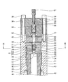
- FIG. 1 is a schematic cross-sectional view showing a fuel injection pump of the present embodiment.
- FIG. 2 is a cross-sectional view showing the main part of the fuel injection pump of the present embodiment.
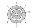
- FIG. 3 is a cross-sectional view taken along the line III-III in FIG.
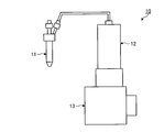
- FIG. 4 is a schematic configuration diagram showing the fuel injection device of the present embodiment.
- FIG. 4 is a schematic configuration diagram showing the fuel injection device of the present embodiment.
- the fuel injection device 10 is mounted on a large marine diesel engine (internal combustion engine) mounted on a ship.
- the fuel injection device 10 includes a fuel injection valve 11, a fuel injection pump 12, and a pressure accumulation pipe control valve block 13.
- the fuel injection valve 11 injects fuel into a combustion chamber of a diesel engine (not shown).
- the fuel injection pump 12 pressure-feeds the fuel to the fuel injection valve 11 and is connected via a fuel pipe 14.
- the accumulation control valve block 13 drives and controls the fuel injection pump 12, and is installed on the side surface of a cylinder block of a diesel engine, etc., and the fuel injection pump 12 configured in a tower shape is disposed above the accumulation control valve block 13. It is set up.
- FIG. 1 is a schematic cross-sectional view showing the fuel injection pump of the present embodiment
- FIG. 2 is a cross-sectional view showing an essential part of the fuel injection pump of the present embodiment
- the fuel injection pump 12 of the present embodiment includes a pump case 21, a plunger barrel 22, a plunger 23, a suction valve 24, and a discharge valve 25.
- the plunger barrel 22, the suction valve 24 and the discharge valve 25 are arranged in series in the pump case 21 so as to form a straight line along the longitudinal direction, and the outer wall surface is supported by the inner wall surface of the pump case 21. It is done.
- the pump case 21 includes a cylindrical case main body 31, a cylindrical case mounting base 32, and a cylindrical pressing member 33.
- the case main body 31 is provided with a first accommodating portion 34 accommodating most of the plunger barrel 22, the suction valve 24, the discharge valve 25 and the like, and a second accommodating portion 35 accommodating the plunger 23 and the like.
- the first housing portion 34 and the second housing portion 35 are formed by a continuous space portion, and the first housing portion 34 is positioned above the second housing portion 35, and the second housing portion 34 is a second housing.
- the inner diameter dimension of the portion 35 is set large.
- An outer peripheral surface of the upper end portion of the case mounting base 32 is engaged with an inner peripheral surface of the lower end portion (second accommodation portion 35) of the case main body 31, and is connected by a connection bolt (not shown).
- the case mounting base 32 is formed with a support hole 36 for movably supporting the plunger 23 along the axial direction at a central portion in the radial direction.
- the lower end of the case mount 32 is fixed to the upper surface of the pressure accumulation control valve block 13 (see FIG. 4).
- the plurality of fastening bolts 39 pass through the respective mounting holes 38 in a state in which the fitting portion 37 is fitted to the first accommodation portion 34 of the case main body 31 and in close contact with the upper end surface of the case main body 31. And screwed into a screw hole 40 formed in the case main body 31 so as to be fixed to the case main body 31.
- the plunger barrel 22 is disposed in the pump case 21 and positioned by the inclined surface 43 abutting on the inclined surface 45 of the projecting portion 44, and movement from this to the first direction (downward in the axial direction) A Are bound.
- the plunger 23 is biased and supported in the first direction A by the biasing force of the return spring 51.
- the return spring 51 is a compression coil spring and is disposed between the plunger 23 and the case body 31.
- a spring receiving member 52 is fixed to a stepped portion of the small diameter portion 47 and the large diameter portion 48.
- a spring receiving portion 53 is formed at a step between the inner wall surface of the first housing portion 34 and the inner wall surface of the second housing portion 35.
- the lower end portion of the return spring 51 resiliently presses the spring receiving member 52, and the upper end portion resiliently presses the spring receiving portion 53, whereby the plunger 23 is biased in the first direction A.
- the plunger 23 can be moved in a second direction B (upward in the axial direction) opposite to the first direction A by the pressure accumulation control valve block 13 (see FIG. 4).
- the suction valve 24 includes a suction valve body 61, a valve body 62, and a compression spring 63.
- the suction valve main body 61 is provided with a small diameter portion 64 on the upper side and a large diameter portion 65 on the lower side, and a fuel passage 66 is formed at the central portion in the radial direction along the axial direction.
- the lower surface of the suction valve main body 61 is in close contact with the upper surface of the plunger barrel 22 so that the fuel compression chamber 67 is located at the radial center by the suction valve 24, the plunger barrel 22 and the plunger 23. It is done.
- a fuel supply and discharge chamber 68 is defined between the small diameter portion 64 of the suction valve main body 61 in the suction valve 24 and the case main body 31 in the pump case 21.
- the fuel supply and discharge chamber 68 is a ring-shaped space, and is in communication with the fuel compression chamber 67 via a plurality of fuel suction passages 69 penetrating the suction valve main body 61 in the radial direction.
- a fuel supply passage 70 and a fuel discharge passage 71 penetrating the case main body 31 in the radial direction are formed at predetermined intervals in the circumferential direction, and the fuel supply passage 70 and the fuel discharge passage 71 are One end communicates with the fuel supply and discharge chamber 68, and the other end is connected to a fuel supply device (not shown).
- the suction valve 24 can suck the fuel supplied from the outside through the fuel supply passage 70 to the fuel supply and discharge chamber 68 from the fuel suction passage 69 to the fuel compression chamber 67. That is, the valve body 62 is disposed in the fuel passage 66 in the suction valve main body 61, is movable in the axial direction, and is pressed against the suction valve seat by the biasing force of the compression spring 63. The communication of the chamber 67 is shut off. Therefore, when the pressure of fuel supplied from the fuel supply passage 70 to the fuel supply and discharge chamber 68 by the fuel supply device and acting on the valve body 62 from the fuel suction passage 69 becomes high, the valve body 62 resists the biasing force of the compression spring 63.
- the discharge valve 25 includes a discharge valve main body 81, a valve body 82, and a compression spring 83.
- a fuel passage 84 is formed at the center in the radial direction along the axial direction, and the lower surface is in close contact with the upper surface of the suction valve 24 so that the fuel passages 66 and 84 communicate in series.
- the discharge valve 25 can discharge the fuel supplied to the fuel compression chamber 67 to the outside. That is, the valve body 82 is disposed in the fuel passage 84 in the discharge valve main body 81, is movable in the axial direction, and presses against the discharge valve seat by the biasing force of the compression spring 83. Blocking the communication of
- the pressing member 33 is provided with the fuel discharge passage 85 at the center in the radial direction, and a spring accommodating portion 86 is provided around the fuel discharge passage 85.
- One end of the fuel discharge passage 85 is in communication with the fuel passage 84, and the connection plug 87 is connected to the other end.
- the spring accommodating portion 86 opens to the discharge valve 25 side, and the compression spring 83 is accommodated.
- the fuel pressure in the fuel compression chamber 67 acts on the valve body 82 through the fuel passage 66.
- the valve body 82 rises against the biasing force of the compression spring 83 and separates from the discharge valve seat, and the fuel passage 66 and the fuel passage 84 communicate with each other. Then, the fuel in the fuel compression chamber 67 flows through the fuel passage 66 to the fuel passage 84 and is discharged to the outside through the fuel discharge passage 85.
- the plunger barrel 22, the suction valve 24 and the discharge valve 25 are arranged in series in the case main body 31 and compressed and held by the holding member 33 in a state in which they are arranged in close contact with each other. That is, the plunger barrel 22, the suction valve 24, and the discharge valve 25 have the same maximum outer diameter dimension according to the inner diameter of the case main body 31, so that they can be easily inserted from the upper portion of the case main body 31. Then, in the case body 31 of the plunger barrel 22, the inclined surface 43 abuts on the inclined surface 45 of the projecting portion 44 and movement in the first direction A is restrained.
- the suction valve 24 is positioned in contact with the upper surface of the plunger barrel 22 in the case main body 31, and the discharge valve 25 is positioned in contact with the upper surface of the suction valve 24 in the case main body 31.
- the plunger barrel 22, the suction valve 24 and the discharge valve 25 are positioned in the radial direction by the outer peripheral surface thereof being supported by the inner peripheral surface of the case main body 31.
- the pressing member 33 is fixed to the case body 31 by a plurality of fastening bolts 39 in a state where the fitting portion 37 is fitted to the case body 31 and the upper surface of the discharge valve 25 is pressed.
- the fuel supply device supplies fuel of a predetermined pressure from the fuel supply passage 70 to the valve body 62 of the suction valve 24 through the fuel supply and discharge chamber 68 and the fuel suction passage 69. Then, since the valve body 62 moves against the biasing force of the compression spring 63 and the fuel suction passage 69 and the fuel compression chamber 67 communicate with each other, the fuel in the fuel supply and discharge chamber 68 is discharged from the fuel suction passage 69. It is drawn into the fuel compression chamber 67.
- the plunger 23 is moved in the second direction B by the accumulation pipe control valve block 13 to pressurize the fuel in the fuel compression chamber 67, and when the fuel pressure exceeds a predetermined pressure, the valve body 82 of the discharge valve 25 Since the fuel passage 66 communicates with the fuel passage 84 by moving against the biasing force of the compression spring 83, the fuel in the fuel compression chamber 67 flows through the fuel passage 66 to the fuel passage 84 and is externally transmitted through the fuel discharge passage 85. Is discharged. Then, the fuel injection valve 11 can inject fuel into the combustion chamber of the diesel engine.
- the fuel compression chamber 67 is partitioned by the plunger 23, the plunger barrel 22 and the plunger 23, and the fuel from the outside can be sucked into the fuel compression chamber 67.
- the fuel in the fuel compression chamber 67 can be discharged to the outside
- a discharge valve 25 is provided, and the plunger barrel 22, the suction valve 24 and the discharge valve 25 are arranged in series along the longitudinal direction in the pump case 21 and the outer wall surface is supported on the inner wall surface of the pump case 21.
- the plunger barrel 22, the suction valve 24 and the discharge valve 25 are arranged in series in the pump case 21 and the outer wall surface is supported by the pump case 21, so that the suction valve 24 and the discharge valve 25 are conventionally provided. It is not necessary to support the plunger by the plunger barrel 22, and the plunger barrel 22 can be miniaturized, and the diameter of the pump case 21 can be reduced. As a result, it is possible to miniaturize the entire fuel injection pump 12 with a small diameter.
- the plunger barrel 22 is restrained from moving in the first direction A by the projecting portion 44 provided on the inner wall surface of the pump case 21, and the suction valve 24 and the discharge valve 25 are in close contact. In the state where it is disposed, it is compressed and held by the pressing member 33. Therefore, the plunger barrel 22, the suction valve 24, and the discharge valve 25 are held in compression in the pump case 21, and tensile stress does not act on the plunger barrel 22 or the like, and the fatigue strength can be improved.
- the maximum outer diameter dimensions of the plunger barrel 22, the suction valve 24, and the discharge valve 25 are set to the same size. Therefore, the plunger barrel 22, the suction valve 24, and the discharge valve 25 can be easily inserted into the pump case 21, and the inner diameter of the inner wall surface of the pump case 21 supporting the plunger barrel 22, the suction valve 24, and the discharge valve 25
- the dimensions can be set to the same dimensions, and the inner diameter machining of the pump case 21 can be simplified to reduce the machining cost, and the plunger barrel 22, the suction valve 24 and the discharge valve 25 can be easily made in the pump case 21. It can be fixed and the assemblability can be improved.
- the fuel injection valve 11 for injecting the fuel into the combustion chamber of the diesel engine, the fuel injection pump 12 for supplying the fuel to the fuel injection valve 11, and the fuel injection pump 12 A pressure accumulation control valve block 13 for controlling the operation of the plunger 23 is provided. Therefore, downsizing and weight reduction of the fuel injection device 10 can be achieved by reducing the entire size of the fuel injection pump 12 to a small diameter.
- the fuel injection device 10 since the fuel injection device 10 is provided, it is possible to miniaturize the entire fuel injection pump 12 with a small diameter, and to reduce the size and weight of the diesel engine.
Landscapes
- Engineering & Computer Science (AREA)
- Chemical & Material Sciences (AREA)
- Combustion & Propulsion (AREA)
- Mechanical Engineering (AREA)
- General Engineering & Computer Science (AREA)
- Fuel-Injection Apparatus (AREA)
Priority Applications (2)
| Application Number | Priority Date | Filing Date | Title |
|---|---|---|---|
| CN201680018967.XA CN107850026B (zh) | 2015-08-04 | 2016-07-20 | 燃料喷射泵、燃料喷射装置、内燃机 |
| KR1020177026087A KR102058785B1 (ko) | 2015-08-04 | 2016-07-20 | 연료 분사 펌프, 연료 분사 장치, 내연 기관 |
Applications Claiming Priority (2)
| Application Number | Priority Date | Filing Date | Title |
|---|---|---|---|
| JP2015154316A JP6546807B2 (ja) | 2015-08-04 | 2015-08-04 | 燃料噴射ポンプ、燃料噴射装置、内燃機関 |
| JP2015-154316 | 2015-08-04 |
Publications (1)
| Publication Number | Publication Date |
|---|---|
| WO2017022482A1 true WO2017022482A1 (ja) | 2017-02-09 |
Family
ID=57942877
Family Applications (1)
| Application Number | Title | Priority Date | Filing Date |
|---|---|---|---|
| PCT/JP2016/071227 Ceased WO2017022482A1 (ja) | 2015-08-04 | 2016-07-20 | 燃料噴射ポンプ、燃料噴射装置、内燃機関 |
Country Status (4)
| Country | Link |
|---|---|
| JP (1) | JP6546807B2 (enExample) |
| KR (1) | KR102058785B1 (enExample) |
| CN (1) | CN107850026B (enExample) |
| WO (1) | WO2017022482A1 (enExample) |
Families Citing this family (2)
| Publication number | Priority date | Publication date | Assignee | Title |
|---|---|---|---|---|
| JP6568613B1 (ja) | 2018-03-09 | 2019-08-28 | 株式会社ジャパンエンジンコーポレーション | 注水ポンプ |
| JP7190860B2 (ja) * | 2018-10-05 | 2022-12-16 | 株式会社ジャパンエンジンコーポレーション | 注水ポンプ |
Citations (4)
| Publication number | Priority date | Publication date | Assignee | Title |
|---|---|---|---|---|
| JPH03168355A (ja) * | 1989-11-29 | 1991-07-22 | Zexel Corp | 燃料噴射ポンプ |
| JP2010101295A (ja) * | 2008-10-27 | 2010-05-06 | Yanmar Co Ltd | 燃料噴射ポンプ |
| JP2013133782A (ja) * | 2011-12-27 | 2013-07-08 | Mitsubishi Heavy Ind Ltd | ディーゼルエンジンの燃料噴射装置、これを備えたディーゼルエンジン、および船舶 |
| JP2015124670A (ja) * | 2013-12-26 | 2015-07-06 | 三井造船株式会社 | 低温液化ガスの吸入・吐出用弁体、往復式ポンプ、及び燃料ガス供給装置 |
Family Cites Families (4)
| Publication number | Priority date | Publication date | Assignee | Title |
|---|---|---|---|---|
| JP3309765B2 (ja) * | 1997-05-16 | 2002-07-29 | 三菱電機株式会社 | 高圧燃料供給ポンプ |
| JP2003097386A (ja) * | 2001-09-27 | 2003-04-03 | Mitsubishi Electric Corp | 高圧燃料供給装置 |
| JP2010275874A (ja) * | 2009-05-26 | 2010-12-09 | Denso Corp | 燃料噴射ポンプ |
| IT1396143B1 (it) * | 2009-11-03 | 2012-11-16 | Magneti Marelli Spa | Pompa carburante con ridotta usura di una guarnizione per un sistema di iniezione diretta |
-
2015
- 2015-08-04 JP JP2015154316A patent/JP6546807B2/ja active Active
-
2016
- 2016-07-20 CN CN201680018967.XA patent/CN107850026B/zh active Active
- 2016-07-20 WO PCT/JP2016/071227 patent/WO2017022482A1/ja not_active Ceased
- 2016-07-20 KR KR1020177026087A patent/KR102058785B1/ko active Active
Patent Citations (4)
| Publication number | Priority date | Publication date | Assignee | Title |
|---|---|---|---|---|
| JPH03168355A (ja) * | 1989-11-29 | 1991-07-22 | Zexel Corp | 燃料噴射ポンプ |
| JP2010101295A (ja) * | 2008-10-27 | 2010-05-06 | Yanmar Co Ltd | 燃料噴射ポンプ |
| JP2013133782A (ja) * | 2011-12-27 | 2013-07-08 | Mitsubishi Heavy Ind Ltd | ディーゼルエンジンの燃料噴射装置、これを備えたディーゼルエンジン、および船舶 |
| JP2015124670A (ja) * | 2013-12-26 | 2015-07-06 | 三井造船株式会社 | 低温液化ガスの吸入・吐出用弁体、往復式ポンプ、及び燃料ガス供給装置 |
Also Published As
| Publication number | Publication date |
|---|---|
| CN107850026B (zh) | 2020-04-14 |
| CN107850026A (zh) | 2018-03-27 |
| JP6546807B2 (ja) | 2019-07-17 |
| KR20170118179A (ko) | 2017-10-24 |
| JP2017031918A (ja) | 2017-02-09 |
| KR102058785B1 (ko) | 2019-12-23 |
Similar Documents
| Publication | Publication Date | Title |
|---|---|---|
| CN103717873B (zh) | 燃料泵 | |
| US9188096B2 (en) | Fuel pump and fuel supply system of internal combustion engine | |
| CN1966967A (zh) | 高压燃料供给泵 | |
| KR19980086462A (ko) | 고압 연료 공급펌프 | |
| KR101787595B1 (ko) | 직접분사식 가솔린 엔진용 고압연료펌프 | |
| US7048521B2 (en) | High pressure fuel supply pump with an intake valve member and a discharge valve member aligned along a plunger axis | |
| CN104428526B (zh) | 用于内燃机的燃料系统的高压燃料泵 | |
| US10883463B2 (en) | High pressure pump | |
| JP6546807B2 (ja) | 燃料噴射ポンプ、燃料噴射装置、内燃機関 | |
| US20150101573A1 (en) | Fluid Injection Assembly | |
| US20180003138A1 (en) | High-pressure pump and production method thereof | |
| US10584700B1 (en) | High-pressure fuel pump | |
| US10240568B2 (en) | Manually actuatable feed pump and fuel system with a feed pump | |
| CN110062846B (zh) | 燃料喷射泵、燃料喷射装置、内燃机 | |
| JP6268279B2 (ja) | 高圧燃料供給ポンプ | |
| JP5851942B2 (ja) | 高圧ポンプ | |
| WO2016117297A1 (ja) | 高圧ポンプ及びその製造方法 | |
| CN108779766B (zh) | 具有流体阻尼器的高压泵 | |
| US10247154B2 (en) | Fuel pump | |
| US9222587B2 (en) | Oil pressure regulator | |
| KR100739939B1 (ko) | 연료 공급 장치 | |
| JPH11107885A (ja) | 流量制御装置およびそれを用いた蓄圧式燃料噴射装置 | |
| KR20000014121A (ko) | 축압식 연료분사 장치 | |
| JP2015068296A (ja) | 燃料噴射ポンプ |
Legal Events
| Date | Code | Title | Description |
|---|---|---|---|
| 121 | Ep: the epo has been informed by wipo that ep was designated in this application |
Ref document number: 16832761 Country of ref document: EP Kind code of ref document: A1 |
|
| ENP | Entry into the national phase |
Ref document number: 20177026087 Country of ref document: KR Kind code of ref document: A |
|
| NENP | Non-entry into the national phase |
Ref country code: DE |
|
| 122 | Ep: pct application non-entry in european phase |
Ref document number: 16832761 Country of ref document: EP Kind code of ref document: A1 |