WO2017018511A1 - 熱間圧延用チタン材 - Google Patents
熱間圧延用チタン材 Download PDFInfo
- Publication number
- WO2017018511A1 WO2017018511A1 PCT/JP2016/072333 JP2016072333W WO2017018511A1 WO 2017018511 A1 WO2017018511 A1 WO 2017018511A1 JP 2016072333 W JP2016072333 W JP 2016072333W WO 2017018511 A1 WO2017018511 A1 WO 2017018511A1
- Authority
- WO
- WIPO (PCT)
- Prior art keywords
- titanium
- surface layer
- slab
- base material
- content
- Prior art date
Links
- 239000000463 material Substances 0.000 title claims abstract description 399
- 239000010936 titanium Substances 0.000 title claims abstract description 391
- RTAQQCXQSZGOHL-UHFFFAOYSA-N Titanium Chemical compound [Ti] RTAQQCXQSZGOHL-UHFFFAOYSA-N 0.000 title claims abstract description 383
- 229910052719 titanium Inorganic materials 0.000 title claims abstract description 377
- 238000005098 hot rolling Methods 0.000 title claims abstract description 136
- 239000002344 surface layer Substances 0.000 claims abstract description 326
- 229910001069 Ti alloy Inorganic materials 0.000 claims abstract description 100
- 239000000203 mixture Substances 0.000 claims abstract description 31
- 239000000126 substance Substances 0.000 claims abstract description 27
- 238000005259 measurement Methods 0.000 claims abstract description 14
- 239000010410 layer Substances 0.000 claims description 156
- 239000012535 impurity Substances 0.000 claims description 37
- BASFCYQUMIYNBI-UHFFFAOYSA-N platinum Chemical group [Pt] BASFCYQUMIYNBI-UHFFFAOYSA-N 0.000 claims description 36
- 238000005096 rolling process Methods 0.000 claims description 36
- 229910052761 rare earth metal Inorganic materials 0.000 claims description 29
- 229910052751 metal Inorganic materials 0.000 claims description 11
- 239000002184 metal Substances 0.000 claims description 11
- 150000003608 titanium Chemical class 0.000 abstract description 7
- 239000000956 alloy Substances 0.000 description 96
- 229910045601 alloy Inorganic materials 0.000 description 91
- 238000000034 method Methods 0.000 description 84
- 230000007797 corrosion Effects 0.000 description 67
- 238000005260 corrosion Methods 0.000 description 67
- 238000012360 testing method Methods 0.000 description 67
- 238000002844 melting Methods 0.000 description 60
- 230000008018 melting Effects 0.000 description 60
- 230000000694 effects Effects 0.000 description 54
- 239000002131 composite material Substances 0.000 description 50
- 238000010438 heat treatment Methods 0.000 description 48
- 229910052739 hydrogen Inorganic materials 0.000 description 48
- 238000004519 manufacturing process Methods 0.000 description 47
- XEEYBQQBJWHFJM-UHFFFAOYSA-N iron Substances [Fe] XEEYBQQBJWHFJM-UHFFFAOYSA-N 0.000 description 44
- 239000001257 hydrogen Substances 0.000 description 42
- UFHFLCQGNIYNRP-UHFFFAOYSA-N Hydrogen Chemical compound [H][H] UFHFLCQGNIYNRP-UHFFFAOYSA-N 0.000 description 39
- 230000003647 oxidation Effects 0.000 description 38
- 238000007254 oxidation reaction Methods 0.000 description 38
- 238000010894 electron beam technology Methods 0.000 description 35
- 238000012545 processing Methods 0.000 description 33
- 229910052760 oxygen Inorganic materials 0.000 description 31
- 230000008569 process Effects 0.000 description 31
- KRHYYFGTRYWZRS-UHFFFAOYSA-N Fluorane Chemical compound F KRHYYFGTRYWZRS-UHFFFAOYSA-N 0.000 description 29
- 229910052742 iron Inorganic materials 0.000 description 29
- 238000005452 bending Methods 0.000 description 28
- PXHVJJICTQNCMI-UHFFFAOYSA-N nickel Substances [Ni] PXHVJJICTQNCMI-UHFFFAOYSA-N 0.000 description 28
- 239000000155 melt Substances 0.000 description 23
- 239000012298 atmosphere Substances 0.000 description 22
- 238000005097 cold rolling Methods 0.000 description 21
- 239000010949 copper Substances 0.000 description 21
- 229910052759 nickel Inorganic materials 0.000 description 21
- 229910052782 aluminium Inorganic materials 0.000 description 20
- 229910052804 chromium Inorganic materials 0.000 description 20
- 239000011651 chromium Substances 0.000 description 20
- 230000002829 reductive effect Effects 0.000 description 20
- 230000005855 radiation Effects 0.000 description 18
- 229910052758 niobium Inorganic materials 0.000 description 17
- 238000005554 pickling Methods 0.000 description 17
- 229910052710 silicon Inorganic materials 0.000 description 17
- 229910052799 carbon Inorganic materials 0.000 description 16
- 239000010408 film Substances 0.000 description 16
- 230000000052 comparative effect Effects 0.000 description 15
- 238000004453 electron probe microanalysis Methods 0.000 description 15
- 238000005242 forging Methods 0.000 description 15
- 229960002050 hydrofluoric acid Drugs 0.000 description 15
- 229910000883 Ti6Al4V Inorganic materials 0.000 description 14
- 230000015556 catabolic process Effects 0.000 description 14
- 238000005204 segregation Methods 0.000 description 14
- 238000003466 welding Methods 0.000 description 14
- 238000005422 blasting Methods 0.000 description 13
- 229910052750 molybdenum Inorganic materials 0.000 description 13
- 238000007711 solidification Methods 0.000 description 13
- 229910052720 vanadium Inorganic materials 0.000 description 13
- 229910052796 boron Inorganic materials 0.000 description 12
- 238000005520 cutting process Methods 0.000 description 12
- 238000009792 diffusion process Methods 0.000 description 12
- 239000011261 inert gas Substances 0.000 description 12
- 229910052757 nitrogen Inorganic materials 0.000 description 12
- 239000000843 powder Substances 0.000 description 12
- 239000002994 raw material Substances 0.000 description 12
- 229910052715 tantalum Inorganic materials 0.000 description 12
- 238000000137 annealing Methods 0.000 description 11
- 229910052802 copper Inorganic materials 0.000 description 11
- 229910052718 tin Inorganic materials 0.000 description 11
- 229910052726 zirconium Inorganic materials 0.000 description 11
- 229910000831 Steel Inorganic materials 0.000 description 10
- 238000010521 absorption reaction Methods 0.000 description 10
- QVGXLLKOCUKJST-UHFFFAOYSA-N atomic oxygen Chemical compound [O] QVGXLLKOCUKJST-UHFFFAOYSA-N 0.000 description 10
- 238000005266 casting Methods 0.000 description 10
- 239000001301 oxygen Substances 0.000 description 10
- 239000010959 steel Substances 0.000 description 10
- 238000004458 analytical method Methods 0.000 description 9
- 229910052748 manganese Inorganic materials 0.000 description 9
- 229910052763 palladium Inorganic materials 0.000 description 8
- 239000011148 porous material Substances 0.000 description 8
- ZOXJGFHDIHLPTG-UHFFFAOYSA-N Boron Chemical compound [B] ZOXJGFHDIHLPTG-UHFFFAOYSA-N 0.000 description 7
- 239000000654 additive Substances 0.000 description 7
- 230000000996 additive effect Effects 0.000 description 7
- 239000011162 core material Substances 0.000 description 7
- 239000013078 crystal Substances 0.000 description 7
- 230000007423 decrease Effects 0.000 description 7
- 230000003287 optical effect Effects 0.000 description 7
- 239000010935 stainless steel Substances 0.000 description 7
- 229910001220 stainless steel Inorganic materials 0.000 description 7
- 229910000521 B alloy Inorganic materials 0.000 description 6
- VEXZGXHMUGYJMC-UHFFFAOYSA-N Hydrochloric acid Chemical compound Cl VEXZGXHMUGYJMC-UHFFFAOYSA-N 0.000 description 6
- 238000005275 alloying Methods 0.000 description 6
- 230000015572 biosynthetic process Effects 0.000 description 6
- 230000000903 blocking effect Effects 0.000 description 6
- 238000000354 decomposition reaction Methods 0.000 description 6
- 238000011156 evaluation Methods 0.000 description 6
- 239000007769 metal material Substances 0.000 description 6
- 239000002245 particle Substances 0.000 description 6
- 238000005498 polishing Methods 0.000 description 6
- 229910052707 ruthenium Inorganic materials 0.000 description 6
- 239000006104 solid solution Substances 0.000 description 6
- 238000007751 thermal spraying Methods 0.000 description 6
- 238000007670 refining Methods 0.000 description 5
- 238000004381 surface treatment Methods 0.000 description 5
- 229910000975 Carbon steel Inorganic materials 0.000 description 4
- 150000001875 compounds Chemical class 0.000 description 4
- 230000007547 defect Effects 0.000 description 4
- 238000006731 degradation reaction Methods 0.000 description 4
- 238000010586 diagram Methods 0.000 description 4
- 238000002149 energy-dispersive X-ray emission spectroscopy Methods 0.000 description 4
- 230000001747 exhibiting effect Effects 0.000 description 4
- 239000000284 extract Substances 0.000 description 4
- 239000012467 final product Substances 0.000 description 4
- 239000010419 fine particle Substances 0.000 description 4
- 150000002431 hydrogen Chemical class 0.000 description 4
- 230000006872 improvement Effects 0.000 description 4
- 238000000691 measurement method Methods 0.000 description 4
- 238000013001 point bending Methods 0.000 description 4
- 239000000047 product Substances 0.000 description 4
- 229920006395 saturated elastomer Polymers 0.000 description 4
- 238000004626 scanning electron microscopy Methods 0.000 description 4
- 239000000243 solution Substances 0.000 description 4
- 230000000087 stabilizing effect Effects 0.000 description 4
- 238000005728 strengthening Methods 0.000 description 4
- 230000035882 stress Effects 0.000 description 4
- 238000009864 tensile test Methods 0.000 description 4
- 238000010998 test method Methods 0.000 description 4
- JQMFQLVAJGZSQS-UHFFFAOYSA-N 2-[4-[2-(2,3-dihydro-1H-inden-2-ylamino)pyrimidin-5-yl]piperazin-1-yl]-N-(2-oxo-3H-1,3-benzoxazol-6-yl)acetamide Chemical compound C1C(CC2=CC=CC=C12)NC1=NC=C(C=N1)N1CCN(CC1)CC(=O)NC1=CC2=C(NC(O2)=O)C=C1 JQMFQLVAJGZSQS-UHFFFAOYSA-N 0.000 description 3
- 229910052684 Cerium Inorganic materials 0.000 description 3
- 229910021369 Ti-1Cu-0.5Nb Inorganic materials 0.000 description 3
- 230000002411 adverse Effects 0.000 description 3
- 239000002775 capsule Substances 0.000 description 3
- 239000010962 carbon steel Substances 0.000 description 3
- -1 chlorine ions Chemical class 0.000 description 3
- 239000011248 coating agent Substances 0.000 description 3
- 238000000576 coating method Methods 0.000 description 3
- 238000005336 cracking Methods 0.000 description 3
- 230000006866 deterioration Effects 0.000 description 3
- 238000009661 fatigue test Methods 0.000 description 3
- 239000007789 gas Substances 0.000 description 3
- 230000001771 impaired effect Effects 0.000 description 3
- 238000005121 nitriding Methods 0.000 description 3
- 238000001556 precipitation Methods 0.000 description 3
- 239000013535 sea water Substances 0.000 description 3
- 238000005245 sintering Methods 0.000 description 3
- 239000007858 starting material Substances 0.000 description 3
- 238000005482 strain hardening Methods 0.000 description 3
- 239000011135 tin Substances 0.000 description 3
- 229910052727 yttrium Inorganic materials 0.000 description 3
- VZSRBBMJRBPUNF-UHFFFAOYSA-N 2-(2,3-dihydro-1H-inden-2-ylamino)-N-[3-oxo-3-(2,4,6,7-tetrahydrotriazolo[4,5-c]pyridin-5-yl)propyl]pyrimidine-5-carboxamide Chemical compound C1C(CC2=CC=CC=C12)NC1=NC=C(C=N1)C(=O)NCCC(N1CC2=C(CC1)NN=N2)=O VZSRBBMJRBPUNF-UHFFFAOYSA-N 0.000 description 2
- WZFUQSJFWNHZHM-UHFFFAOYSA-N 2-[4-[2-(2,3-dihydro-1H-inden-2-ylamino)pyrimidin-5-yl]piperazin-1-yl]-1-(2,4,6,7-tetrahydrotriazolo[4,5-c]pyridin-5-yl)ethanone Chemical compound C1C(CC2=CC=CC=C12)NC1=NC=C(C=N1)N1CCN(CC1)CC(=O)N1CC2=C(CC1)NN=N2 WZFUQSJFWNHZHM-UHFFFAOYSA-N 0.000 description 2
- QGZKDVFQNNGYKY-UHFFFAOYSA-N Ammonia Chemical compound N QGZKDVFQNNGYKY-UHFFFAOYSA-N 0.000 description 2
- OKTJSMMVPCPJKN-UHFFFAOYSA-N Carbon Chemical compound [C] OKTJSMMVPCPJKN-UHFFFAOYSA-N 0.000 description 2
- RYGMFSIKBFXOCR-UHFFFAOYSA-N Copper Chemical compound [Cu] RYGMFSIKBFXOCR-UHFFFAOYSA-N 0.000 description 2
- 229910017945 Cu—Ti Inorganic materials 0.000 description 2
- 229910000722 Didymium Inorganic materials 0.000 description 2
- 241000224487 Didymium Species 0.000 description 2
- 229910001122 Mischmetal Inorganic materials 0.000 description 2
- 229910052779 Neodymium Inorganic materials 0.000 description 2
- 229910052777 Praseodymium Inorganic materials 0.000 description 2
- QAOWNCQODCNURD-UHFFFAOYSA-N Sulfuric acid Chemical compound OS(O)(=O)=O QAOWNCQODCNURD-UHFFFAOYSA-N 0.000 description 2
- 229910021366 Ti-1Cu Inorganic materials 0.000 description 2
- 229910000905 alloy phase Inorganic materials 0.000 description 2
- RYXHOMYVWAEKHL-UHFFFAOYSA-N astatine atom Chemical compound [At] RYXHOMYVWAEKHL-UHFFFAOYSA-N 0.000 description 2
- 230000004888 barrier function Effects 0.000 description 2
- 238000009835 boiling Methods 0.000 description 2
- 239000004568 cement Substances 0.000 description 2
- 230000008859 change Effects 0.000 description 2
- 239000003795 chemical substances by application Substances 0.000 description 2
- 239000000460 chlorine Substances 0.000 description 2
- 229910052801 chlorine Inorganic materials 0.000 description 2
- 238000011109 contamination Methods 0.000 description 2
- 238000001816 cooling Methods 0.000 description 2
- 238000009826 distribution Methods 0.000 description 2
- 238000005516 engineering process Methods 0.000 description 2
- 238000001125 extrusion Methods 0.000 description 2
- 150000004678 hydrides Chemical class 0.000 description 2
- 238000005984 hydrogenation reaction Methods 0.000 description 2
- 238000009863 impact test Methods 0.000 description 2
- 238000005304 joining Methods 0.000 description 2
- 229910052746 lanthanum Inorganic materials 0.000 description 2
- 239000007788 liquid Substances 0.000 description 2
- 239000011777 magnesium Substances 0.000 description 2
- 229910052749 magnesium Inorganic materials 0.000 description 2
- 238000000465 moulding Methods 0.000 description 2
- 239000003758 nuclear fuel Substances 0.000 description 2
- 238000005457 optimization Methods 0.000 description 2
- 230000010355 oscillation Effects 0.000 description 2
- 230000035515 penetration Effects 0.000 description 2
- 230000002093 peripheral effect Effects 0.000 description 2
- 239000002244 precipitate Substances 0.000 description 2
- 238000002360 preparation method Methods 0.000 description 2
- 238000000746 purification Methods 0.000 description 2
- 238000007789 sealing Methods 0.000 description 2
- 238000000926 separation method Methods 0.000 description 2
- 230000008023 solidification Effects 0.000 description 2
- 238000005507 spraying Methods 0.000 description 2
- 238000003860 storage Methods 0.000 description 2
- 239000000758 substrate Substances 0.000 description 2
- 238000002560 therapeutic procedure Methods 0.000 description 2
- 239000010409 thin film Substances 0.000 description 2
- XLYOFNOQVPJJNP-UHFFFAOYSA-N water Substances O XLYOFNOQVPJJNP-UHFFFAOYSA-N 0.000 description 2
- OHVLMTFVQDZYHP-UHFFFAOYSA-N 1-(2,4,6,7-tetrahydrotriazolo[4,5-c]pyridin-5-yl)-2-[4-[2-[[3-(trifluoromethoxy)phenyl]methylamino]pyrimidin-5-yl]piperazin-1-yl]ethanone Chemical compound N1N=NC=2CN(CCC=21)C(CN1CCN(CC1)C=1C=NC(=NC=1)NCC1=CC(=CC=C1)OC(F)(F)F)=O OHVLMTFVQDZYHP-UHFFFAOYSA-N 0.000 description 1
- IHCCLXNEEPMSIO-UHFFFAOYSA-N 2-[4-[2-(2,3-dihydro-1H-inden-2-ylamino)pyrimidin-5-yl]piperidin-1-yl]-1-(2,4,6,7-tetrahydrotriazolo[4,5-c]pyridin-5-yl)ethanone Chemical compound C1C(CC2=CC=CC=C12)NC1=NC=C(C=N1)C1CCN(CC1)CC(=O)N1CC2=C(CC1)NN=N2 IHCCLXNEEPMSIO-UHFFFAOYSA-N 0.000 description 1
- CONKBQPVFMXDOV-QHCPKHFHSA-N 6-[(5S)-5-[[4-[2-(2,3-dihydro-1H-inden-2-ylamino)pyrimidin-5-yl]piperazin-1-yl]methyl]-2-oxo-1,3-oxazolidin-3-yl]-3H-1,3-benzoxazol-2-one Chemical compound C1C(CC2=CC=CC=C12)NC1=NC=C(C=N1)N1CCN(CC1)C[C@H]1CN(C(O1)=O)C1=CC2=C(NC(O2)=O)C=C1 CONKBQPVFMXDOV-QHCPKHFHSA-N 0.000 description 1
- WTFUTSCZYYCBAY-SXBRIOAWSA-N 6-[(E)-C-[[4-[2-(2,3-dihydro-1H-inden-2-ylamino)pyrimidin-5-yl]piperazin-1-yl]methyl]-N-hydroxycarbonimidoyl]-3H-1,3-benzoxazol-2-one Chemical compound C1C(CC2=CC=CC=C12)NC1=NC=C(C=N1)N1CCN(CC1)C/C(=N/O)/C1=CC2=C(NC(O2)=O)C=C1 WTFUTSCZYYCBAY-SXBRIOAWSA-N 0.000 description 1
- DFGKGUXTPFWHIX-UHFFFAOYSA-N 6-[2-[4-[2-(2,3-dihydro-1H-inden-2-ylamino)pyrimidin-5-yl]piperazin-1-yl]acetyl]-3H-1,3-benzoxazol-2-one Chemical compound C1C(CC2=CC=CC=C12)NC1=NC=C(C=N1)N1CCN(CC1)CC(=O)C1=CC2=C(NC(O2)=O)C=C1 DFGKGUXTPFWHIX-UHFFFAOYSA-N 0.000 description 1
- 238000012935 Averaging Methods 0.000 description 1
- BTBUEUYNUDRHOZ-UHFFFAOYSA-N Borate Chemical compound [O-]B([O-])[O-] BTBUEUYNUDRHOZ-UHFFFAOYSA-N 0.000 description 1
- ZOXJGFHDIHLPTG-BJUDXGSMSA-N Boron-10 Chemical compound [10B] ZOXJGFHDIHLPTG-BJUDXGSMSA-N 0.000 description 1
- VEXZGXHMUGYJMC-UHFFFAOYSA-M Chloride anion Chemical compound [Cl-] VEXZGXHMUGYJMC-UHFFFAOYSA-M 0.000 description 1
- VYZAMTAEIAYCRO-UHFFFAOYSA-N Chromium Chemical compound [Cr] VYZAMTAEIAYCRO-UHFFFAOYSA-N 0.000 description 1
- DGAQECJNVWCQMB-PUAWFVPOSA-M Ilexoside XXIX Chemical compound C[C@@H]1CC[C@@]2(CC[C@@]3(C(=CC[C@H]4[C@]3(CC[C@@H]5[C@@]4(CC[C@@H](C5(C)C)OS(=O)(=O)[O-])C)C)[C@@H]2[C@]1(C)O)C)C(=O)O[C@H]6[C@@H]([C@H]([C@@H]([C@H](O6)CO)O)O)O.[Na+] DGAQECJNVWCQMB-PUAWFVPOSA-M 0.000 description 1
- FYYHWMGAXLPEAU-UHFFFAOYSA-N Magnesium Chemical compound [Mg] FYYHWMGAXLPEAU-UHFFFAOYSA-N 0.000 description 1
- NIPNSKYNPDTRPC-UHFFFAOYSA-N N-[2-oxo-2-(2,4,6,7-tetrahydrotriazolo[4,5-c]pyridin-5-yl)ethyl]-2-[[3-(trifluoromethoxy)phenyl]methylamino]pyrimidine-5-carboxamide Chemical compound O=C(CNC(=O)C=1C=NC(=NC=1)NCC1=CC(=CC=C1)OC(F)(F)F)N1CC2=C(CC1)NN=N2 NIPNSKYNPDTRPC-UHFFFAOYSA-N 0.000 description 1
- AFCARXCZXQIEQB-UHFFFAOYSA-N N-[3-oxo-3-(2,4,6,7-tetrahydrotriazolo[4,5-c]pyridin-5-yl)propyl]-2-[[3-(trifluoromethoxy)phenyl]methylamino]pyrimidine-5-carboxamide Chemical compound O=C(CCNC(=O)C=1C=NC(=NC=1)NCC1=CC(=CC=C1)OC(F)(F)F)N1CC2=C(CC1)NN=N2 AFCARXCZXQIEQB-UHFFFAOYSA-N 0.000 description 1
- 229910001257 Nb alloy Inorganic materials 0.000 description 1
- 229910020012 Nb—Ti Inorganic materials 0.000 description 1
- GRYLNZFGIOXLOG-UHFFFAOYSA-N Nitric acid Chemical compound O[N+]([O-])=O GRYLNZFGIOXLOG-UHFFFAOYSA-N 0.000 description 1
- 239000004698 Polyethylene Substances 0.000 description 1
- 229910001154 Pr alloy Inorganic materials 0.000 description 1
- 229910052772 Samarium Inorganic materials 0.000 description 1
- VYPSYNLAJGMNEJ-UHFFFAOYSA-N Silicium dioxide Chemical compound O=[Si]=O VYPSYNLAJGMNEJ-UHFFFAOYSA-N 0.000 description 1
- 206010040844 Skin exfoliation Diseases 0.000 description 1
- 229910021368 Ti-1.5Al Inorganic materials 0.000 description 1
- GWEVSGVZZGPLCZ-UHFFFAOYSA-N Titan oxide Chemical compound O=[Ti]=O GWEVSGVZZGPLCZ-UHFFFAOYSA-N 0.000 description 1
- XSQUKJJJFZCRTK-UHFFFAOYSA-N Urea Chemical compound NC(N)=O XSQUKJJJFZCRTK-UHFFFAOYSA-N 0.000 description 1
- 239000002253 acid Substances 0.000 description 1
- 150000007513 acids Chemical class 0.000 description 1
- 230000009471 action Effects 0.000 description 1
- 230000032683 aging Effects 0.000 description 1
- 229910021529 ammonia Inorganic materials 0.000 description 1
- 229910052789 astatine Inorganic materials 0.000 description 1
- 230000008901 benefit Effects 0.000 description 1
- ZOMBKNNSYQHRCA-UHFFFAOYSA-J calcium sulfate hemihydrate Chemical compound O.[Ca+2].[Ca+2].[O-]S([O-])(=O)=O.[O-]S([O-])(=O)=O ZOMBKNNSYQHRCA-UHFFFAOYSA-J 0.000 description 1
- XFWJKVMFIVXPKK-UHFFFAOYSA-N calcium;oxido(oxo)alumane Chemical compound [Ca+2].[O-][Al]=O.[O-][Al]=O XFWJKVMFIVXPKK-UHFFFAOYSA-N 0.000 description 1
- 239000004202 carbamide Substances 0.000 description 1
- 239000003054 catalyst Substances 0.000 description 1
- 239000000919 ceramic Substances 0.000 description 1
- KRVSOGSZCMJSLX-UHFFFAOYSA-L chromic acid Substances O[Cr](O)(=O)=O KRVSOGSZCMJSLX-UHFFFAOYSA-L 0.000 description 1
- 238000005253 cladding Methods 0.000 description 1
- 238000005345 coagulation Methods 0.000 description 1
- 230000015271 coagulation Effects 0.000 description 1
- 229910021540 colemanite Inorganic materials 0.000 description 1
- 238000010276 construction Methods 0.000 description 1
- 230000008094 contradictory effect Effects 0.000 description 1
- 238000010612 desalination reaction Methods 0.000 description 1
- 230000002708 enhancing effect Effects 0.000 description 1
- AWJWCTOOIBYHON-UHFFFAOYSA-N furo[3,4-b]pyrazine-5,7-dione Chemical compound C1=CN=C2C(=O)OC(=O)C2=N1 AWJWCTOOIBYHON-UHFFFAOYSA-N 0.000 description 1
- 238000000227 grinding Methods 0.000 description 1
- 229910052735 hafnium Inorganic materials 0.000 description 1
- 230000006698 induction Effects 0.000 description 1
- 238000007689 inspection Methods 0.000 description 1
- 229910052741 iridium Inorganic materials 0.000 description 1
- 238000004898 kneading Methods 0.000 description 1
- 238000003475 lamination Methods 0.000 description 1
- 238000004093 laser heating Methods 0.000 description 1
- 238000010309 melting process Methods 0.000 description 1
- 229910044991 metal oxide Inorganic materials 0.000 description 1
- 150000004706 metal oxides Chemical class 0.000 description 1
- 230000029052 metamorphosis Effects 0.000 description 1
- 230000004048 modification Effects 0.000 description 1
- 238000012986 modification Methods 0.000 description 1
- 239000010955 niobium Substances 0.000 description 1
- 229910017604 nitric acid Inorganic materials 0.000 description 1
- 229910052756 noble gas Inorganic materials 0.000 description 1
- 239000003921 oil Substances 0.000 description 1
- 229910052762 osmium Inorganic materials 0.000 description 1
- 230000001590 oxidative effect Effects 0.000 description 1
- 229910052697 platinum Inorganic materials 0.000 description 1
- 229920000573 polyethylene Polymers 0.000 description 1
- 238000004663 powder metallurgy Methods 0.000 description 1
- 238000009703 powder rolling Methods 0.000 description 1
- 238000010248 power generation Methods 0.000 description 1
- 230000001737 promoting effect Effects 0.000 description 1
- 230000001681 protective effect Effects 0.000 description 1
- 239000002901 radioactive waste Substances 0.000 description 1
- 238000001959 radiotherapy Methods 0.000 description 1
- 150000002910 rare earth metals Chemical class 0.000 description 1
- 230000001105 regulatory effect Effects 0.000 description 1
- 239000011347 resin Substances 0.000 description 1
- 229920005989 resin Polymers 0.000 description 1
- 230000002441 reversible effect Effects 0.000 description 1
- 229910052703 rhodium Inorganic materials 0.000 description 1
- 229910052706 scandium Inorganic materials 0.000 description 1
- 229910052814 silicon oxide Inorganic materials 0.000 description 1
- 239000011734 sodium Substances 0.000 description 1
- 229910052708 sodium Inorganic materials 0.000 description 1
- 239000002904 solvent Substances 0.000 description 1
- 125000006850 spacer group Chemical group 0.000 description 1
- 239000007921 spray Substances 0.000 description 1
- 229910052717 sulfur Inorganic materials 0.000 description 1
- OGIDPMRJRNCKJF-UHFFFAOYSA-N titanium oxide Inorganic materials [Ti]=O OGIDPMRJRNCKJF-UHFFFAOYSA-N 0.000 description 1
- XJDNKRIXUMDJCW-UHFFFAOYSA-J titanium tetrachloride Chemical compound Cl[Ti](Cl)(Cl)Cl XJDNKRIXUMDJCW-UHFFFAOYSA-J 0.000 description 1
- 230000009466 transformation Effects 0.000 description 1
- 239000011800 void material Substances 0.000 description 1
- 238000000304 warm extrusion Methods 0.000 description 1
- 239000013585 weight reducing agent Substances 0.000 description 1
- 229910000859 α-Fe Inorganic materials 0.000 description 1
Images


Classifications
-
- B—PERFORMING OPERATIONS; TRANSPORTING
- B21—MECHANICAL METAL-WORKING WITHOUT ESSENTIALLY REMOVING MATERIAL; PUNCHING METAL
- B21B—ROLLING OF METAL
- B21B1/00—Metal-rolling methods or mills for making semi-finished products of solid or profiled cross-section; Sequence of operations in milling trains; Layout of rolling-mill plant, e.g. grouping of stands; Succession of passes or of sectional pass alternations
- B21B1/38—Metal-rolling methods or mills for making semi-finished products of solid or profiled cross-section; Sequence of operations in milling trains; Layout of rolling-mill plant, e.g. grouping of stands; Succession of passes or of sectional pass alternations for rolling sheets of limited length, e.g. folded sheets, superimposed sheets, pack rolling
-
- B—PERFORMING OPERATIONS; TRANSPORTING
- B21—MECHANICAL METAL-WORKING WITHOUT ESSENTIALLY REMOVING MATERIAL; PUNCHING METAL
- B21B—ROLLING OF METAL
- B21B3/00—Rolling materials of special alloys so far as the composition of the alloy requires or permits special rolling methods or sequences ; Rolling of aluminium, copper, zinc or other non-ferrous metals
-
- B—PERFORMING OPERATIONS; TRANSPORTING
- B23—MACHINE TOOLS; METAL-WORKING NOT OTHERWISE PROVIDED FOR
- B23K—SOLDERING OR UNSOLDERING; WELDING; CLADDING OR PLATING BY SOLDERING OR WELDING; CUTTING BY APPLYING HEAT LOCALLY, e.g. FLAME CUTTING; WORKING BY LASER BEAM
- B23K15/00—Electron-beam welding or cutting
-
- B—PERFORMING OPERATIONS; TRANSPORTING
- B23—MACHINE TOOLS; METAL-WORKING NOT OTHERWISE PROVIDED FOR
- B23K—SOLDERING OR UNSOLDERING; WELDING; CLADDING OR PLATING BY SOLDERING OR WELDING; CUTTING BY APPLYING HEAT LOCALLY, e.g. FLAME CUTTING; WORKING BY LASER BEAM
- B23K20/00—Non-electric welding by applying impact or other pressure, with or without the application of heat, e.g. cladding or plating
- B23K20/04—Non-electric welding by applying impact or other pressure, with or without the application of heat, e.g. cladding or plating by means of a rolling mill
-
- C—CHEMISTRY; METALLURGY
- C22—METALLURGY; FERROUS OR NON-FERROUS ALLOYS; TREATMENT OF ALLOYS OR NON-FERROUS METALS
- C22C—ALLOYS
- C22C14/00—Alloys based on titanium
-
- C—CHEMISTRY; METALLURGY
- C22—METALLURGY; FERROUS OR NON-FERROUS ALLOYS; TREATMENT OF ALLOYS OR NON-FERROUS METALS
- C22F—CHANGING THE PHYSICAL STRUCTURE OF NON-FERROUS METALS AND NON-FERROUS ALLOYS
- C22F1/00—Changing the physical structure of non-ferrous metals or alloys by heat treatment or by hot or cold working
- C22F1/16—Changing the physical structure of non-ferrous metals or alloys by heat treatment or by hot or cold working of other metals or alloys based thereon
- C22F1/18—High-melting or refractory metals or alloys based thereon
-
- C—CHEMISTRY; METALLURGY
- C22—METALLURGY; FERROUS OR NON-FERROUS ALLOYS; TREATMENT OF ALLOYS OR NON-FERROUS METALS
- C22F—CHANGING THE PHYSICAL STRUCTURE OF NON-FERROUS METALS AND NON-FERROUS ALLOYS
- C22F1/00—Changing the physical structure of non-ferrous metals or alloys by heat treatment or by hot or cold working
Definitions
- the present invention relates to a titanium material for hot rolling.
- Titanium material has excellent properties such as corrosion resistance, oxidation resistance, fatigue resistance, hydrogen embrittlement resistance, and neutron blocking properties. These properties can be achieved by adding various alloying elements to titanium.
- Titanium materials are light and have excellent corrosion resistance, so they are used in seawater cooling condensers in power plants, heat exchangers for seawater desalination plants, chemical plant reactors, and coolers.
- Industrial pure titanium exhibits excellent corrosion resistance particularly in an environment containing nitric acid, chromic acid, seawater, and an environment containing chloride ions.
- high corrosion resistance cannot be expected in an environment containing hydrochloric acid or sulfuric acid, and crevice corrosion may occur in an environment containing chlorine ions or the like.
- Titanium materials have been used in the aircraft field due to their excellent specific strength and corrosion resistance, and are also widely used in exhaust systems for automobiles and motorcycles.
- JIS type 2 industrial pure titanium material is used mainly for motorcycles in place of conventional stainless steel materials.
- heat resistant titanium alloys having higher heat resistance have been used in place of JIS class 2 industrial pure titanium materials.
- a muffler equipped with a catalyst used at high temperatures is also used to remove harmful components of exhaust gas.
- the temperature of the exhaust gas exceeds 700 ° C and may temporarily reach 800 ° C. For this reason, materials used for exhaust devices are required to have strength at a temperature of about 800 ° C., oxidation resistance, etc., and an index of high temperature heat resistance of a creep rate at 600 to 700 ° C. has become important. ing.
- such a heat-resistant titanium alloy needs to add an element that improves high-temperature strength and oxidation resistance such as Al, Cu, and Nb, and is higher in cost than industrial pure titanium.
- Patent Document 1 describes Al: 0.5 to 2.3% (in this specification, “%” for chemical components means “% by mass” unless otherwise specified). A titanium alloy excellent in cold workability and high-temperature strength is disclosed.
- Patent Document 2 Japanese Patent Laid-Open No. 2001-89821 includes Fe: more than 1% and 5% or less, O (oxygen): 0.05 to 0.75%, and Si: 0.01 ⁇ e 0. Titanium alloy having excellent oxidation resistance and corrosion resistance, including 5 [Fe] to 5 ⁇ e ⁇ 0.5 [Fe] ([Fe] indicates the content (% by mass) in the alloy, and e is a constant of natural logarithm) Is shown).
- Patent Document 3 discloses a heat-resistant titanium alloy plate excellent in cold workability containing Al: 0.30 to 1.50% and Si: 0.10 to 1.0%, and The manufacturing method is disclosed.
- JP-A-2009-68026 contains Cu: 0.5 to 1.8%, Si: 0.1 to 0.6%, O: 0.1% or less. Accordingly, there is disclosed a titanium alloy containing Nb: 0.1 to 1.0%, with the balance being Ti and unavoidable impurities coated with a protective film.
- JP 2013-142183 A includes Si: 0.1 to 0.6%, Fe: 0.04 to 0.2%, and O: 0.02 to 0.15%.
- a titanium alloy containing a total content of Fe and O of 0.1 to 0.3% and having a balance of Ti and inevitable impurity elements at 700 ° C. and excellent oxidation resistance at 800 ° C. is disclosed. ing.
- Industrial titanium cold-rolled sheet materials for example, pure titanium cold-rolled sheet materials for industrial use
- plate materials such as plate heat exchangers and FC separators.
- industrial titanium cold-rolled sheet materials are also required to be thin by improving fatigue strength and to have a high added environment (under high load).
- Patent Document 6 plasma nitriding is performed on a titanium product made of pure titanium, ⁇ -type titanium alloy, ⁇ -type titanium alloy, or ⁇ + ⁇ -type titanium alloy, and the object of processing is disclosed.
- a compound existing on the surface of the hardened layer by performing a plasma nitriding treatment for forming a hardened layer on the surface of the metal and a fine particle collision treatment for causing one or more kinds of fine particles to collide with the treatment target after the plasma nitriding treatment
- a method is disclosed in which the fatigue strength is improved by surface modification of a titanium product by removing the layer.
- Patent Document 7 discloses a step A of performing fine particle peening on the surface of a substrate made of a titanium alloy and titanium, a step B of performing a first heat treatment in a temperature zone T1, and a temperature zone. Step C in which the second heat treatment is performed in T2 and Step D in which the third heat treatment is performed in the temperature zone T3 are sequentially provided, satisfying the relationship of T1> T2> T3, and T1 being set to 900 to 1000 ° C.
- a surface treatment method for a substrate made of a titanium alloy and titanium is disclosed.
- an amorphous layer, a fine particle layer ( ⁇ phase, particle size: about 300 nm), a submicron particle layer ( ⁇ phase, particle) are formed in the vicinity of the surface of the titanium material in this order from the surface side.
- Industrially pure titanium is mainly composed of an ⁇ phase having an hcp (dense hexagonal lattice) structure, and it is known that when a large amount of hydrogen is absorbed in the ⁇ phase, a hydride is formed and embrittles. For this reason, depending on the use environment, there is a case where an accident occurs in which hydrogen is absorbed and becomes brittle and breaks.
- Non-Patent Document 1 for example, accidents due to hydrogen absorption in a plant that handles non-oxidizing acids, or in a urea / ammonia environment or a hydrogen gas environment are reported. For this reason, a titanium alloy material excellent in hydrogen embrittlement resistance has been proposed.
- Patent Document 8 discloses a titanium alloy containing 50% by volume or more of a ⁇ phase and containing 500 to 6000 ppm of hydrogen and having a large elongation at break. Even if it contains a large amount of hydrogen, it is brittle. An example is shown that does not.
- neutron beam shielding plates that can shield thermal neutrons are used.
- the neutron shielding effect is highest for boron 10 ( 10 B), which is 19.9% of natural B.
- Stainless steel containing B is generally used as a material for the neutron beam shielding plate.
- Patent Document 9 Japanese Examined Patent Publication No. 58-6704 includes Kuna Copite (2MgO ⁇ 3B 2 O 2 ⁇ 13H 2 O), Meyerhot Ferrite (3CaO ⁇ 3B 2 O 2 ⁇ 7H 2 O), Colemanite (2CaO ⁇ 3B). 2 O 2 ⁇ 5H 2 O), a cured molded body obtained by kneading and molding a borate aggregate containing crystal water such as hemihydrate gypsum and calcium aluminate cement with water, and containing 5 mass of B A neutron beam blocking material containing at least% is disclosed.
- the neutron beam shielding material disclosed in Patent Document 9 is made of cement, there are problems in terms of corrosion resistance, manufacturability, and workability.
- Patent Document 10 Japanese Patent Publication No. 1-168833
- Patent Document 10 uses a hot-rolled sheet of boron-containing titanium alloy containing B in an amount of 0.1 to 10% by mass and the balance being titanium and inevitable impurities. It is disclosed.
- Patent Document 11 describes a boron-containing material (NaB 4 O 7 , B 2 O 3 , PbO, Fe 2 O 3, etc.) in a hollow metal casing, A radiation shielding material filled with a metal oxide mixed therein to be solidified is disclosed. According to Patent Document 11, neutron beams are mainly blocked by boron and hydrogen, and gamma rays are blocked by a casing and a metal therein.
- the titanium material is usually manufactured by the method shown below.
- the raw material titanium oxide is chlorinated to titanium tetrachloride by the crawl method, and then reduced with magnesium or sodium to produce a lump-like sponge-like metal titanium (sponge titanium).
- This sponge titanium is press-molded to form a titanium consumable electrode, and a titanium ingot is manufactured by vacuum arc melting using the titanium consumable electrode as an electrode.
- an alloy element is added as necessary to produce a titanium alloy ingot.
- the titanium alloy ingot is divided, forged and rolled into a titanium slab, and the titanium slab is further subjected to hot rolling, annealing, pickling, cold rolling, and vacuum heat treatment to produce a titanium thin plate.
- titanium ingot is smashed, hydroground, dehydrogenated, powder crushed, and classified to produce titanium powder, and titanium powder is powder-rolled, sintered, and cold-rolled.
- the manufacturing method is also known.
- JP 2011-42828 discloses that titanium powder is produced directly from sponge titanium, not a titanium ingot, and a titanium thin plate is produced from the obtained titanium powder.
- Sintered compacts are manufactured by sintering pre-sintered compacts made of viscous compositions containing agents and solvents into thin sheets, and sintered compacts are manufactured by compacting the sintered compacts.
- a method is disclosed in which the fracture elongation of the sintered thin plate is 0.4% or more, the density ratio is 80% or more, and the density ratio of the sintered compacted plate is 90% or more. ing.
- Patent Document 13 discloses a composite powder obtained by adding an appropriate amount of iron powder, chromium powder or copper powder to titanium alloy powder made from titanium alloy scrap or titanium alloy ingot. After extruding the carbon steel capsule, the capsule on the surface of the obtained round bar is dissolved and removed, and further solution treatment or solution treatment and aging treatment are performed to produce a titanium alloy with excellent quality by the powder method A method is disclosed.
- a sponge capsule is filled with a sponge titanium powder and then subjected to warm extrusion at an extrusion ratio of 1.5 or more and an extrusion temperature of 700 ° C. or less.
- a method for producing a titanium molded body in which 20% or more of the total length of the grain boundary of the molded body is in metal contact is performed by performing outer peripheral processing excluding copper.
- a pack rolling method is known as a technique for rolling the sheet.
- the pack rolling method is a method in which a core material such as a titanium alloy having poor workability is covered with a cover material such as inexpensive carbon steel having good workability and hot rolling is performed.
- a release agent is applied to the surface of the core material, and at least two upper and lower surfaces thereof are covered with a cover material, or the four peripheral surfaces are covered with a spacer material in addition to the upper and lower surfaces, and the surroundings are welded. Assembled and hot rolled.
- a core material which is a material to be rolled, is covered with a cover material and hot rolled. Therefore, the core material surface does not directly contact a cold medium (atmosphere or roll), and the temperature drop of the core material can be suppressed, so that even a core material with poor workability can be manufactured.
- Patent Document 15 discloses a method of assembling a hermetically sealed box
- Patent Document 16 discloses a degree of vacuum of 10 ⁇ 3 torr or more.
- a method of manufacturing a hermetically sealed box by sealing the cover material is disclosed, and further, Japanese Patent Application Laid-Open No. 11-057810 (Patent Document 17) discloses a method in which the cover material is covered with carbon steel (cover material) on the order of 10 ⁇ 2 torr.
- a method for producing a hermetic coated box by sealing by high energy density welding under the following vacuum is disclosed.
- Patent Document 18 steel is used as a base material and titanium or a titanium alloy is used as a base material, and the joint surface between the base material and the base material is evacuated and then welded and assembled.
- a method for manufacturing a titanium clad steel sheet in which an assembly slab for rolling is joined by hot rolling is disclosed.
- Patent Document 19 discloses that pure nickel, pure iron and a carbon content of 0.01% by mass or less on the surface of a base steel material containing 0.03% by mass or more of carbon. After the titanium foil material is laminated by interposing an insert material made of any one of the above-mentioned low carbon steels with a thickness of 20 ⁇ m or more, a laser beam is irradiated from either side of the lamination direction, A method of manufacturing a titanium-coated steel material by melting and joining at least the vicinity of the edge with a base steel material over the entire circumference is disclosed.
- Patent Document 20 the surface of a porous titanium raw material (sponge titanium) formed into an ingot shape is melted using an electron beam under vacuum to make the surface layer portion dense titanium.
- the titanium ingot is manufactured and hot rolled and cold rolled to form a porous portion in which the porous titanium raw material is formed into an ingot shape, and the entire surface of the porous portion composed of dense titanium.
- a method for producing a dense titanium material (titanium ingot) having a dense coating portion for coating with very little energy is exemplified.
- Patent Document 21 Japanese Patent Application Laid-Open No. Sho 62-270277 describes that surface effect treatment of an engine member for automobiles is performed by thermal spraying.
- Titanium processing technology edited by Japan Titanium Association, Nikkan Kogyo Shimbun, p. 214-230, issued in November 1992
- a titanium alloy with improved corrosion resistance contains a rare and expensive platinum group element, and thus its production cost is significantly increased.
- titanium alloy disclosed in Patent Document 1 contains Al, it adversely affects the formability, particularly the stretch formability in which processing occurs in the direction in which the thickness decreases.
- Patent Document 4 Although the titanium alloy disclosed in Patent Document 4 has sufficient workability and oxidation resistance, it contains a large amount of expensive Nb, resulting in high alloy costs.
- Patent Document 5 Although the titanium alloy disclosed in Patent Document 5 also has sufficient high-temperature oxidation characteristics, the entire surface of the plate is alloyed, so that the alloy cost becomes high.
- Patent Document 6 and Patent Document 7 requires a special surface treatment for the titanium material, and an increase in manufacturing cost is inevitable.
- the hot-rolled sheet disclosed in Patent Document 10 has a high B content, and thus cannot be inevitably increased in cost, has poor workability, and is actually difficult to use as a neutron beam shielding plate.
- the radiation shielding material disclosed in Patent Document 11 is a metal casing material filled with a boron-containing material, and is difficult to process after the boron-containing material is filled.
- sponge titanium is press-molded to form a titanium consumable electrode, and a titanium ingot is manufactured by vacuum arc melting using the titanium consumable electrode as an electrode.
- the titanium slab was forged and rolled into a titanium slab, and the titanium slab was manufactured by hot rolling, annealing, pickling, and cold rolling.
- a process of dissolving titanium and producing a titanium ingot was always added.
- a method of producing titanium powder by powder rolling, sintering, and cold rolling is also known, but in the method of producing titanium powder from a titanium ingot, a step of dissolving titanium is also added.
- the core material covered with the cover material is slab or ingot to the last, and has undergone a melting process or is made of expensive titanium powder, and the manufacturing cost cannot be reduced.
- Patent Document 20 although a dense titanium material can be produced with very little energy, the surface of the titanium sponge formed into an ingot shape is dissolved, and the dense titanium surface layer portion and the internal components are the same type of pure titanium. Or it is prescribed
- thermal spraying is a method in which a film is formed by melting metal, ceramics, or the like and spraying it on the surface of a titanium material.
- a film is formed by this method, the formation of pores in the film cannot be avoided.
- thermal spraying is performed while shielding with an inert gas in order to avoid oxidation of the film.
- inert gases are entrained in the pores of the coating.
- Such pores containing the inert gas are not pressed by hot working or the like.
- vacuum heat treatment is generally carried out, but during this treatment, the inert gas in the pores may expand and the film may be peeled off.
- the abundance ratio (porosity) of pores generated by thermal spraying is several vol. % Or more and 10 vol. % May be exceeded.
- a titanium material having a high porosity in the film has a risk of peeling in the manufacturing process, and there is a risk that a defect such as a crack during processing may occur.
- melt resolidification process As a process for melting and resolidifying the surface layer of the slab using an electron beam.
- the melted and re-solidified surface layer is removed in a pickling step after hot rolling.
- the present inventors paid attention to this melt resolidification treatment. That is, the present inventors can form a surface layer portion containing a specific alloy element in the slab by melting a specific alloy element when melting the slab surface layer and solidifying it with a slab-derived component. I thought.
- the melt resolidification treatment for the purpose of suppressing surface flaws during hot rolling cannot be used as it is to form a surface layer portion containing a specific alloy element in the slab. This is because the conventional melt resolidification treatment is based on the premise that the formed surface layer is removed by pickling, and no consideration was given to segregation of alloy components in the surface layer portion.
- the content of alloying elements added to improve various properties required for titanium materials such as corrosion resistance, oxidation resistance, fatigue resistance, hydrogen embrittlement resistance, and neutron barrier properties (express target characteristics) It is an object of the present invention to obtain a titanium material for hot rolling having desired characteristics at a low cost by reducing the amount of the specific alloying element used) and suppressing the production cost of the titanium material.
- the present invention has been made to solve the above-mentioned problems, and the gist thereof is the following titanium material for hot rolling.
- Titanium for hot rolling comprising a base material made of industrial pure titanium or a titanium alloy, and a surface layer portion having a chemical composition different from that of the base material formed on at least one rolling surface of the base material.
- the surface layer part has a thickness of 2.0 to 20.0 mm, the ratio of the total thickness to 40% or less per side, and the content of elements contained in the surface layer part is plural.
- / C AVE ⁇ 100 is 40% or less This is a titanium material for hot rolling.
- the platinum group element is Pd and / or Ru.
- the chemical composition is mass%, Rare earth element: 0.001 to 0.2%, The titanium material for hot rolling according to (2) or (3) above.
- the titanium material for hot rolling of the present invention is a material (slabs such as slabs, blooms and billets) subjected to hot working, and after hot working, cold working, heat treatment, etc. are performed as necessary. And processed into a titanium composite.
- the titanium material for hot rolling according to the present invention will be described with reference to the drawings.
- “%” regarding the content of each element means “mass%”.
- This titanium material for hot rolling 1 has the same characteristics as the whole titanium material made of the same titanium alloy, but can be manufactured at low cost.
- the dimension in case the titanium material for hot rolling is a rectangular titanium cast piece will not be specifically limited if it is a dimension which can be used for hot rolling as it is.
- the rectangular titanium cast piece has a thickness of about 50 to 300 mm, a length of about 3000 to 10000 m, and a width of 600. It may be about ⁇ 1500 mm.
- the thickness of the surface layer portion is set to 2.0 to 20.0 mm.
- the ratio of the thickness of the surface layer part to the total thickness is 40% or less per side.
- Base material Base material 1 consists of industrial pure titanium or a titanium alloy. However, by using a titanium alloy, mechanical properties (strength, ductility, etc.) superior to the case of using industrial pure titanium can be obtained.
- JIS 1 to 4 types of industrial pure titanium can be used among the pure titanium specified in JIS. That is, it contains 0.1% or less C, 0.015% or less H, 0.4% or less O, 0.07% or less N, 0.5% or less Fe, and the balance is Ti. Pure titanium for industrial use. If these JIS 1 to 4 kinds of industrial pure titanium are used, a titanium material that has sufficient workability, does not generate cracks, and is integrated with the surface titanium alloy after hot working can be obtained.
- ⁇ -type, ⁇ + ⁇ -type, and ⁇ -type titanium alloys can be used as the base material 1.
- the ⁇ -type titanium alloy for example, Ti-0.5Cu, Ti-1.0Cu, Ti-1.0Cu-0.5Nb, Ti-1.0Cu-1.0Sn-0.3Si-0. 25Nb, Ti-0.5Al-0.45Si, Ti-0.9Al-0.35Si, Ti-3Al-2.5V, Ti-5Al-2.5Sn, Ti-6Al-2Sn-4Zr-2Mo, Ti- Examples thereof include 6Al-2.75Sn-4Zr-0.4Mo-0.45Si.
- ⁇ -type titanium alloy for example, Ti-11.5Mo-6Zr-4.5Sn, Ti-8V-3Al-6Cr-4Mo-4Zr, Ti-10V-2Fe-3Mo, Ti-13V-11Cr-3Al Ti-15V-3Al-3Cr-3Sn, Ti-6.8Mo-4.5Fe-1.5Al, Ti-20V-4Al-1Sn, Ti-22V-4Al, and the like.
- the base material may be manufactured by a known manufacturing method such as a melting method or a powder metallurgy method, and is not particularly limited.
- the base material can be manufactured by cutting and refining an ingot into a slab or billet shape by breakdown.
- breakdown since the surface is relatively flat by breakdown, it is easy to disperse the element containing the alloy element relatively uniformly, and it is easy to make the element distribution of the alloy phase uniform.
- an ingot directly produced during casting can be used as a base material.
- the cutting and refining process can be omitted, it can be manufactured at a lower cost.
- the surface is cut and refined after the ingot is manufactured, the same effect can be expected when it is manufactured through breakdown.
- Surface Layer Portion 1a is made of a titanium alloy having a chemical composition different from that of the base material as described above. There is no particular restriction on the chemical composition of the titanium alloy. It is known that titanium alloys are generally classified into ⁇ type, ⁇ + ⁇ type and ⁇ type. Further, there are Al, O, N and the like as the ⁇ stabilizing element, V, Mo, Cr, Fe, Nb, Ta and the like as the ⁇ stabilizing element, and Zr, It is known that there are Sn and Hf.
- Table 1 shows elements that are known to contribute to the improvement of the characteristics by being contained in the titanium alloy.
- the titanium alloy according to the present invention is, for example, in mass%, O: 0 to 0.5%, N: 0 to 0.2%, C: 0 to 2.0%, Al: 0 to 8.0%, Sn: 0 to 10.0%, Zr: 0 to 20.0%, Mo: 0 to 25.0%, Ta: 0 to 5.0%, V: 0 to 30.0%, Nb: 0 to 40 0.0%, Si: 0 to 2.0%, Fe: 0 to 5.0%, Cr: 0 to 10.0%, Cu: 0 to 3.0%, Co: 0 to 3.0%, Ni : 0 to 2.0%, platinum group element: 0 to 0.5%, rare earth element: 0 to 0.5%, B: 0 to 5.0%, and Mn: 0 to 10.0% By containing more than 1% of one or more of them, the target function can be imparted to the surface of the titanium material.
- Elements that can be contained in titanium with elements other than those described above depend on the strength of solid solution strengthening and precipitation strengthening (sometimes not forming a solid solution and sometimes forming precipitates) and elements to be contained as general knowledge of metal materials. Can improve the creep characteristics. Examples of these elements include elements from hydrogen (1) to astatine (85) by atomic number (excluding the noble gas elements which are Group 18 elements), and a total of about 5% is allowed.
- Impurities can be contained within a range that does not hinder the target characteristics, and other impurities mainly include impurity elements mixed from raw materials and scrap and elements mixed during production. Examples include C, N, O, Fe , H and the like are representative elements, and other elements such as Mg and Cl are mixed from raw materials, and elements such as Si, Al and S are mixed during production. If these elements are about 2% or less, it is considered that the target characteristics of the present application are not impaired.
- the titanium alloy according to the present invention is, for example, in mass%, O: 0.01 to 0.5%, N: 0.01 to 0.2%, C: 0.01. -2.0%, Al: 0.1-8.0%, Sn: 0.1-10.0%, Zr: 0.5-20.0%, Mo: 0.1-25.0%, Ta: 0.1-5.0%, V: 1.0-30.0%, Nb: 0.1-40.0%, Si: 0.1-2.0%, Fe: 0.01- 5.0%, Cr: 0.1-10.0%, Cu: 0.3-3.0%, Co: 0.05-3.0%, Ni: 0.05-2.0%, platinum Group element: 0.01 to 0.5%, rare earth element: 0.001 to 0.5%, B: 0.01 to 5.0%, and Mn: 0.1 to 10.0% One or more of them may be contained.
- the titanium alloy according to the present invention has O: 0.02 to 0.4%, N: 0.01 to 0.15%, C: 0.01 to 1.0%, Al: 0.2 to 6.0 %, Sn: 0.15 to 5.0%, Zr: 0.5 to 10.0%, Mo: 0.2 to 20.0%, Ta: 0.1 to 3.0%, V: 2.
- Nb 0.15-5.0%
- Si 0.1-1.0%
- Fe 0.05-2.0%
- Cr 0.2-5.0%
- Cu 0.3-2.0%
- Co 0.05-2.0%
- Ni 0.1-1.0%
- platinum group element 0.02-0.4%
- rare earth element It is more preferable to contain one or more selected from 0.001 to 0.3%, B: 0.1 to 5.0%, and Mn: 0.2 to 8.0%, and O: 0.03-0.3%, N: 0.01-0.1%, C: 0.01-0.5% Al: 0.4 to 5.0%, Sn: 0.2 to 3.0%, Zr: 0.5 to 5.0%, Mo: 0.5 to 15.0%, Ta: 0.2 to 2.0%, V: 5.0 to 20.0%, Nb: 0.2 to 2.0%, Si: 0.15 to 0.8%, Fe: 0.1 to 1.0%, Cr : 0.2-3.0%, Cu: 0.3-1.5%, Co: 0.1-1.0%, Ni: 0.1-0.8%, Platinum group element: 0.03
- titanium alloy having a chemical component not defined in JIS other than the above can also be used.
- it is as follows. Titanium alloys having heat resistance: Ti-6Al-2Sn-4Zr-2Mo-0.08Si, Ti-6Al-5Zr-0.5Mo-0.2Si, Ti-8Al-1Mo-1V, etc.
- Low alloy and high strength titanium alloy Ti-1 to 1.5Fe-0.3 to 0.5O-0.01 to 0.04N.
- Low alloy and heat resistant titanium alloys Ti-1Cu, Ti-1Cu-0.5Nb, Ti-1Cu-1Sn-0.35Si-0.5Nb, etc. Titanium alloy having excellent creep resistance: Ti-6Al-2Sn-4Zr-6Mo, etc.
- Titanium alloys with high strength and good cold workability Ti-15V-3Cr-3Sn-3Al, Ti-20V-4Al-1Sn, etc. Titanium alloy having high strength and toughness: Ti-10V-2Fe-3Al and the like. Titanium alloy with excellent wear resistance: Ti-6Al-4V-10Cr-1.3C, etc.
- At least one of the surface layer portions 1a contains an alloy element that exhibits target characteristics, and the balance is titanium and impurities.
- the following are illustrated as an alloy element which expresses a target characteristic, it is not this limitation.
- (D) Alloy element exhibiting hydrogen embrittlement resistance: one or more selected from Mo, V and Nb having Mo equivalent in the range of 8.0 to 20.0 (where Mo equivalent Mo content (mass) %) + V content (mass%) / 1.5 + Nb content (mass%) / 3.6.
- Platinum group elements 0.01-0.25%
- the platinum group element can be contained as an alloy element that has the effect of lowering the hydrogenation voltage of the titanium alloy and maintaining the natural potential in the immobile zone, and exhibits corrosion resistance. If the platinum group element content (the total content in the case of containing a plurality of platinum group elements) is less than 0.01%, the corrosion resistance will be insufficient, and if it exceeds 0.25%, the corrosion resistance will not be improved much. Not only can it not be expected, it also causes a rise in raw material costs. When a platinum group element is contained, the content is set to 0.01 to 0.25%.
- the platinum group element content is preferably 0.03% or more, and more preferably 0.05% or more. Moreover, it is preferable that it is 0.20% or less, and it is more preferable that it is 0.15% or less.
- the rare earth elements include Sc, Y, light rare earth elements (La to Eu), and heavy rare earth elements (Gd to Lu).
- the above effect can be expected when any rare earth element is added.
- the same effect can be expected when a rare earth mixture or compound such as a mixed rare earth element (Misch metal, Mm) or didymium alloy (Nd—Pr alloy) before separation and purification is used.
- the oxidation of titanium takes an oxidation form called so-called inward diffusion that occurs when oxygen diffuses in the oxide film and binds to titanium on the surface. Therefore, if the diffusion of oxygen is suppressed, the oxidation is suppressed.
- an alloy element such as Si or Nb is added in order to improve oxidation resistance at a high temperature of 600 to 800 ° C.
- Si silicon oxide is formed on the surface layer when exposed to a high-temperature atmosphere to serve as a barrier, so that diffusion of oxygen into the titanium is suppressed and oxidation resistance is improved.
- Nb is dissolved in the oxide film of titanium. Since titanium is tetravalent, whereas titanium is pentavalent, the oxygen vacancy concentration in the oxide film is lowered, and oxygen diffusion in the oxide film is reduced. Is suppressed.
- the surface layer portion of the titanium material for hot rolling is as follows: Various alloy elements listed in the above may be included.
- Si 0.1 to 0.6%
- Si has an action of improving the oxidation resistance at a high temperature of 600 to 800 ° C.
- the Si content is less than 0.1%, there is little allowance for improving oxidation resistance.
- the Si content exceeds 0.6%, the influence on the oxidation resistance is saturated and the workability not only at room temperature but also at a high temperature is remarkably lowered. Therefore, when Si is contained, its content is set to 0.1 to 0.6%.
- the Si content is preferably 0.15% or more, and more preferably 0.20% or more. Moreover, it is preferable that it is 0.55% or less, and it is more preferable that it is 0.50% or less.
- Ta 0.3 to 1.0% Ta also has the effect of improving the oxidation resistance at high temperatures.
- the Ta content is 0.3% or more.
- Ta content is set to 0.3 to 1.0%.
- the Ta content is preferably 0.4% or more, and more preferably 0.5% or more. Moreover, it is preferable that it is 0.9% or less, and it is more preferable that it is 0.8% or less.
- Sn 0 to 1.5%
- Sn is an ⁇ -phase stabilizing element and is an element that increases the high-temperature strength in the same manner as Cu. However, if the Sn content exceeds 1.5%, twin deformation is suppressed and workability at room temperature is reduced. Therefore, when it contains Sn, the content shall be 1.5% or less.
- the Sn content is preferably 1.3% or less, and more preferably 1.2% or less. When it is desired to obtain the above effects, the Sn content is preferably 0.2% or more, and more preferably 0.5% or more.
- Cu 0 to 1.5%
- Cu is an element that increases the high-temperature strength. Moreover, since it dissolves in the ⁇ phase to a certain degree, the ⁇ phase is not generated even when used at a high temperature. However, if the Cu content exceeds 1.5%, a ⁇ phase is generated depending on the temperature. Therefore, when it contains Cu, the content shall be 1.5% or less.
- the Cu content is preferably 1.4% or less, and more preferably 1.2% or less.
- the Cn content is preferably 0.2% or more, and more preferably 0.4% or more.
- Fe 0 to 0.5%
- Fe is a ⁇ -phase stabilizing element, but if it is in a small amount, the formation of ⁇ -phase is small and the oxidation resistance is not greatly affected. However, if the Fe content exceeds 0.5%, the amount of ⁇ -phase generated increases and the oxidation resistance is degraded. Therefore, when Fe is contained, the content is set to 0.5% or less.
- the Fe content is preferably 0.4% or less, and more preferably 0.3% or less.
- the total content of Sn, Cu and Fe exceeds 2.5%, the workability at room temperature is lowered, and a ⁇ phase is generated depending on the temperature. For this reason, when it contains 1 or more types selected from Sn, Cu, and Fe, it is preferable that the total content shall be 2.5% or less.
- Impurities can be contained within a range that does not hinder the target characteristics, and other impurities are mainly impurity elements such as Cr, V, Cr, Mn, and Mo as impurity elements mixed from scrap. In combination with C, N, O and H, a total amount of 5% or less is acceptable.
- the surface layer contains elements derived from slabs (base materials). Therefore, the content of each element in the surface layer means the content of elements not included in the slab, and the increase in content (increased content from the base material) of elements included in the slab. To do.
- the balance other than the above is titanium and impurities. Impurities can be contained as long as the target characteristics are not impaired, and other impurities are mainly impurity elements mixed from scrap, such as Sn, Mo, V, Mn, Nb, Si, Cu, Co, Pd, Ru, There are Ta, Y, La, Ce, and the like, and together with general impurity elements C, N, O, and H, a total amount of 5% or less is acceptable.
- the layer for obtaining hydrogen absorption resistance is a titanium alloy layer containing a certain range of ⁇ -stabilizing elements.
- the reason for prescribing the formation of the ⁇ phase is that the ⁇ phase of titanium forms a hydride even at a hydrogen concentration of only a few tens of ppm, whereas the ⁇ phase of the titanium alloy can dissolve about 1000 ppm or more of hydrogen, This is because it has the characteristic that it is difficult to cause embrittlement due to hydrogen.
- the lower limit of the Mo equivalent is the amount of alloy necessary to obtain a sufficient amount of ⁇ phase.
- the upper limit was determined because a titanium alloy with a large amount of alloy addition is not suitable for use because of its high cost.
- the surface layer contains elements derived from slabs (base materials). Therefore, the content of each element in the surface layer means the content of elements not included in the slab, and the increase in content (increased content from the base material) of elements included in the slab. To do.
- B 0.1-3.0% In B, 19.9% of 10 B exists, but this 10 B has a large absorption cross section of thermal neutrons and a large shielding effect of neutron beams. If the B content is less than 0.1%, a sufficient neutron beam shielding effect cannot be obtained. If the B content exceeds 3.0%, cracking during hot rolling and deterioration of workability may occur.
- the titanium alloy containing B can be produced by adding a boride such as B or TiB 2 to titanium.
- a boride such as B or TiB 2
- a 10 B enriched boron-containing material 10 B content is approximately 90% or more
- H 3 10 BO 3 , 10 B 2 O 10 B 4 C is used, neutron beams even if the B content is small Since the shielding effect is large, it is extremely effective.
- H and O are also concentrated in the alloy layer. However, if H is removed from the material during heat treatment such as vacuum annealing, it is a problem. If O and C are 0.4 mass% O or less and 0.1 mass% C or less, which are below the upper limit contained in industrial pure titanium, they can be produced without any problem.
- Impurities can be contained within a range not impairing the target characteristics, and other impurities are mainly impurity elements mixed from scrap such as Cr, Ta, Al, V, Cr, Nb, Si, Sn, Mn, Mo and There is Cu or the like, and a total amount of 5% or less together with C, N, Fe, O, and H, which are general impurity elements, is acceptable.
- the surface layer contains elements derived from slabs (base materials). Therefore, the content of each element in the surface layer means the content of elements not included in the slab, and the increase in content (increased content from the base material) of elements included in the slab. To do.
- Titanium composite material The titanium material for hot rolling of the present invention is a material (slab, slab, bloom, billet, etc.) subjected to hot working, and after hot working, if necessary, cold working, It is processed into titanium composite by heat treatment.
- the titanium composite material includes an inner layer derived from the base material of the titanium material for hot rolling according to the present invention and a surface layer derived from the surface layer portion.
- the surface layer contains the alloy elements (a) to (e)
- each case will be described individually.
- the thickness of the surface layer in contact with the external environment is too thin, sufficient corrosion resistance cannot be obtained.
- the thickness of the surface layer varies depending on the thickness of the material used for production or the subsequent processing rate, but if it is 2 ⁇ m or more, a sufficient effect is exhibited. Therefore, the thickness of the surface layer is preferably 2 ⁇ m or more, and more preferably 5 ⁇ m or more.
- the ratio of the thickness of the surface layer portion 1a to the total thickness of the titanium composite material is desirably 40% or less, more desirably 30% or less per one surface.
- the porosity can be easily measured by taking a photograph of the cross section of the material by observing it with an optical microscope and processing the photograph. An arbitrary 10 to 20 points in the cross section are observed, the porosity is measured, and the average can be set as the overall porosity.
- the porosity of the material which performed hot rolling or after cold rolling is equivalent to the porosity of the titanium material for hot rolling.
- the specific element in the surface layer portion can be measured using EPMA or GDS. Specifically, arbitrary 10 to 20 locations on the surface layer portion are measured, and the average value of the increased content from the base material at each measured location is defined as the increased content C 0 at each measured location, and the increased content C 0. May be the average value C AVE of the increased content in the surface layer portion.
- the thickness of the intermediate layer can be measured using EPMA or GDS. If GDS is used, more detailed measurement is possible. In the case of GDS, after removing the surface layer to some extent by polishing, the thickness of the intermediate layer can be measured by performing GDS analysis in the depth direction from the surface.
- the intermediate layer is the increased content from the base material (in the case of an element not included in the base material, its content, in the case of an element also included in the base material, the increase in content from the base material) ) Is C MID, and the average of the increased content in the surface layer portion is C AVE , it means a region of 0 ⁇ C MID ⁇ 0.8 ⁇ C AVE .
- the thickness of the surface layer in contact with the external environment is too thin, sufficient oxidation resistance cannot be obtained.
- the thickness of the surface layer varies depending on the thickness of the material used for production or the subsequent processing rate, but if it is 5 ⁇ m or more, the effect is sufficiently exhibited. Therefore, the thickness of the surface layer is preferably 5 ⁇ m or more, and more preferably 10 ⁇ m or more.
- the ratio of the thickness of the surface layer to the total thickness of the titanium composite material is desirably 40% or less, more desirably 30% or less per one surface.
- the porosity of the surface layer is preferably 0.1% or less. When the porosity exceeds 0.1%, the surface layer may be swollen or peeled off during hot rolling.
- the specific element in the surface layer portion can be measured using EPMA or GDS. Specifically, arbitrary 10 to 20 locations on the surface layer portion are measured, and the average value of the increased content from the base material at each measured location is defined as the increased content C 0 at each measured location, and the increased content C 0. May be the average value C AVE of the increased content in the surface layer portion.
- the thickness of the intermediate layer can be measured using EPMA or GDS. If GDS is used, more detailed measurement is possible. In the case of GDS, after removing the surface layer to some extent by polishing, the thickness of the intermediate layer can be measured by performing GDS analysis in the depth direction from the surface.
- the intermediate layer is the increased content from the base material (in the case of an element not included in the base material, its content, in the case of an element also included in the base material, the increase in content from the base material) ) Is C MID, and the average of the increased content in the surface layer portion is C AVE , it means a region of 0 ⁇ C MID ⁇ 0.8 ⁇ C AVE .
- the thickness of each surface layer is preferably 100 ⁇ m or less, and more preferably 50 ⁇ m or less. Further, the ratio of the thickness of the surface layer to the total thickness of the titanium composite material is desirably 20% or less per side, and more desirably 10% or less.
- the porosity of the surface layer is preferably 0.1% or less. When the porosity exceeds 0.1%, the surface layer may be swollen or peeled off during hot rolling.
- the titanium composite has an elongation at break in the direction perpendicular to the rolling direction of 25% or more.
- the elongation is greatly affected, and the larger the elongation, the better the moldability.
- the thickness of the intermediate layer can be measured using EPMA or GDS. If GDS is used, more detailed measurement is possible. In the case of GDS, after removing the surface layer to some extent by polishing, the thickness of the intermediate layer can be measured by performing GDS analysis in the depth direction from the surface.
- the intermediate layer is the increased content from the base material (in the case of an element not included in the base material, its content, in the case of an element also included in the base material, the increase in content from the base material) ) Is C MID, and the average of the increased content in the surface layer portion is C AVE , it means a region of 0 ⁇ C MID ⁇ 0.8 ⁇ C AVE .
- the thickness of the surface layer depends on the thickness of the surface layer portion 1a and the processing rate at the time of hot processing performed thereafter.
- the porosity of the surface layer is preferably 0.1% or less. When the porosity exceeds 0.1%, the surface layer may be swollen or peeled off during hot rolling.
- the surface layer includes an intermediate layer in the vicinity of the inner layer. That is, the titanium material for hot rolling of the present invention is provided with a surface layer portion formed by, for example, melt resolidification treatment on the surface of the base material, and the surface layer portion is then subjected to hot rolling heating, and In the heat treatment step after cold rolling, diffusion occurs at the interface between the base material and the surface layer portion, and when the titanium composite material is finally finished, it is between the inner layer derived from the base material and the surface layer derived from the surface layer portion. An intermediate layer is formed. This intermediate layer bonds the inner layer and the surface layer to each other and bonds them firmly. Further, since a continuous element gradient is generated in the intermediate layer, the difference in strength between the inner layer and the surface layer can be reduced, and cracks during processing can be suppressed.
- the thickness of this intermediate layer is preferably 0.5 ⁇ m or more.
- the porosity can be easily measured by taking a photograph of the cross section of the material by observing it with an optical microscope and processing the photograph. An arbitrary 10 to 20 points in the cross section are observed, the porosity is measured, and the average can be set as the overall porosity.
- the porosity of the material which performed hot rolling or after cold rolling is equivalent to the porosity of the titanium material for hot rolling.
- the specific element in the surface layer portion can be measured using EPMA or GDS. Specifically, arbitrary 10 to 20 locations on the surface layer portion are measured, and the average value of the increased content from the base material at each measured location is defined as the increased content C 0 at each measured location, and the increased content C 0. May be the average value C AVE of the increased content in the surface layer portion.
- the surface layer includes an intermediate layer in the vicinity of the inner layer. That is, the titanium material for hot rolling of the present invention is provided with a surface layer portion formed by, for example, melt resolidification treatment on the surface of the base material, and the surface layer portion is then subjected to hot rolling heating, and In the heat treatment step after cold rolling, diffusion occurs at the interface between the base material and the surface layer portion, and when the titanium composite material is finally finished, it is between the inner layer derived from the base material and the surface layer derived from the surface layer portion. An intermediate layer is formed. This intermediate layer bonds the inner layer and the surface layer to each other and bonds them firmly. Further, since a continuous element gradient is generated in the intermediate layer, the difference in strength between the inner layer and the surface layer can be reduced, and cracks during processing can be suppressed.
- the thickness of this intermediate layer is preferably 0.5 ⁇ m or more.
- the thickness of the intermediate layer can be measured using EPMA or GDS. If GDS is used, more detailed measurement is possible. In the case of GDS, after removing the surface layer to some extent by polishing, the thickness of the intermediate layer can be measured by performing GDS analysis in the depth direction from the surface.
- the intermediate layer is the increased content from the base material (in the case of an element not included in the base material, its content, in the case of an element also included in the base material, the increase in content from the base material) ) Is C MID, and the average of the increased content in the surface layer portion is C AVE , it means a region of 0 ⁇ C MID ⁇ 0.8 ⁇ C AVE .
- the melt resolidification method of the surface layer is carried out as shown in FIG. 5 in the case of a rectangular slab. That is, among the outer surfaces of the rectangular slab 10, at least two wide surfaces 10A and 10B that become the rolling surfaces (surfaces in contact with the hot rolling roll) in the hot rolling process are irradiated with an electron beam, and the surfaces on the surfaces are irradiated. Only melt the layer.
- the surface 10A is one of the two surfaces 10A and 10B.
- the area of the electron beam irradiation region 14 by the single electron beam irradiation gun 12 on the surface 10A of the rectangular slab 10 is compared with the total area of the surface 10A to be irradiated.
- the electron beam irradiation is actually performed while continuously moving the electron beam irradiation gun 12 or continuously moving the rectangular slab 10. It is normal.
- the shape and area of this irradiation area can be adjusted by adjusting the focus of the electron beam or by using an electromagnetic lens to oscillate a small beam at a high frequency (oscillation Oscillation) to form a beam bundle. can do.
- the moving direction of the electron beam irradiation gun is not particularly limited, it is generally continuous along the length direction (usually the casting direction D) or the width direction (usually the direction perpendicular to the casting direction D) of the rectangular slab 10.
- the irradiation region 14 is continuously irradiated in a band shape with a width W (in the case of a circular beam or beam bundle, a diameter W).
- the electron beam irradiation is performed in a belt shape while continuously moving the irradiation gun 12 in the reverse direction (or the same direction) in the adjacent unirradiated belt region.
- a plurality of irradiation guns may be used to simultaneously perform electron beam irradiation on a plurality of regions.
- FIG. 5 the case where a rectangular beam is continuously moved along the length direction (usually casting direction D) of the rectangular slab 10 is shown.
- the surface (surface 10A) of the rectangular titanium cast piece 10 is irradiated with an electron beam by such a surface heat treatment step and heated to melt the surface, the rectangular titanium as shown in the left side of the center of FIG.
- the surface layer of the surface 10A of the slab 10 is melted at the maximum by a depth corresponding to the heat input.
- the depth from the direction perpendicular to the irradiation direction of the electron beam is not constant as shown in FIG. 7, and the depth becomes the largest at the central part of the electron beam irradiation, and the thickness increases toward the strip-shaped end part. Decreases, resulting in a downwardly convex curved shape.
- the surface layer of the material for hot rolling is alloyed by melting and resolidifying together with the material composed of the target alloy element.
- a material used in this case one or more of powder, chip, wire, thin film, cutting powder, and mesh may be used.
- the component and amount of the material to be arranged before melting are determined so that the component in the element concentration region after melting and solidifying together with the material surface becomes the target component.
- the melt resolidification treatment After the melt resolidification treatment, it is preferable to hold at a temperature of 100 ° C. or higher and lower than 500 ° C. for 1 hour or longer. If it is cooled rapidly after melting and resolidification, fine cracks may occur in the surface layer due to strain during solidification. In the subsequent hot rolling process and cold rolling process, the fine cracks may be the starting point, and the surface layer may be peeled off, or a part having a partially thin alloy layer may be generated. Further, if the inside is oxidized due to fine cracks, it is necessary to remove in the pickling process, and the thickness of the alloy layer is further reduced. By maintaining at the above temperature, fine cracks on the surface can be suppressed. At this temperature, atmospheric oxidation hardly occurs even if the temperature is maintained.
- the titanium material for hot rolling provided with a surface layer portion formed by melt re-solidification treatment on the surface of the base material is used at the interface between the base material and the surface layer portion in the subsequent heat treatment process during hot rolling and after cold rolling.
- This intermediate layer makes the said inner layer and the said surface layer metal-bond, and joins firmly.
- a continuous element gradient is generated in the intermediate layer, the difference in strength between the inner layer and the surface layer can be reduced, and cracks during processing can be suppressed.
- the shape of the melted portion is curved as described above, so that the shape is also inherited in the final product.
- the alloy element diffuses and joins from the interface with the curved base material, so if the element diffusion direction is only in the depth direction In addition, diffusion also occurs in the width direction. Therefore, the gradient of the alloy element in the intermediate portion between the base material and the alloy layer occurs not only in the depth direction but also in the width direction.
- the surface of the base material may be melted and re-solidified, and a titanium plate containing a predetermined alloy component may be attached to the surface layer portion to manufacture a titanium material for hot rolling.
- FIG. 8 is an explanatory view schematically showing that a titanium rectangular cast piece (slab) 6 and a titanium plate 7 in which a surface layer portion is formed by melting and resolidifying the surface of a base material are bonded together by welding in a vacuum.
- FIG. 9 is an explanatory view schematically showing that the titanium plates 7 and 8 are bonded together by welding not only on the surface of the titanium rectangular cast slab (slab) 6 but also on the side surfaces.
- the titanium rectangular slab 6 (slab) 6 in which the surface of the base material is formed by melting and re-solidifying the base material surface is referred to as “titanium slab 6”.
- the surface layer 3 of the titanium composite material is bonded by hot rolling cladding. , 4 are alloyed. That is, after the titanium plate 7 containing the alloy element is bonded to the surface corresponding to the rolling surface of the titanium slab 6, the titanium slab 6 and titanium are preferably welded at least in the periphery by the weld 9 in a vacuum vessel. The space between the plates 7 is sealed with a vacuum, and the titanium slab 6 and the titanium plate 7 are bonded together by rolling. In welding the titanium plate 7 to the titanium slab 6, for example, as shown in FIGS. 8 and 7, the entire circumference is welded so that air does not enter between the titanium slab 6 and the titanium plate 7.
- Titanium is an active metal and forms a strong passive film on the surface when left in the atmosphere. It is impossible to remove the oxidized layer on the surface. However, unlike stainless steel, etc., oxygen easily dissolves in titanium. Therefore, when heated in a vacuum and sealed without external oxygen supply, oxygen on the surface diffuses into the solid solution. Therefore, the passive film formed on the surface disappears. Therefore, the titanium slab 6 and the titanium plate 7 on the surface thereof can be completely adhered to each other by the hot-rolled clad method without any inclusions being generated therebetween.
- the titanium slab 6 when an as-cast slab is used as the titanium slab 6, surface defects are generated in the subsequent hot rolling process due to coarse crystal grains generated during solidification.
- the titanium plate 7 when the titanium plate 7 is bonded to the rolled surface of the titanium slab 6 as in the present invention, the bonded titanium plate 7 has a fine structure, so that surface defects in the hot rolling process can be suppressed.
- a titanium plate 7 is bonded to only one surface of the titanium slab 6 in a vacuum as shown in FIG. You may hot-roll without sticking 7.
- a titanium plate 7 may be bonded to both sides of the titanium slab 6 instead of just one side.
- production of the hot rolling in a hot rolling process can be suppressed as mentioned above.
- at least a part of the side surface of the titanium slab 6 usually wraps around the surface side of the hot-rolled sheet by being rolled down by the titanium slab 6. Therefore, if the structure of the surface layer on the side surface of the titanium slab 6 is coarse or a large number of defects are present, surface flaws may occur on the surface near both ends in the width direction of the hot-rolled sheet. For this reason, as shown in FIG.
- the same standard titanium plate 8 is preferably bonded and welded to the side surface of the titanium slab 6 on the edge side during hot rolling as well as the rolled surface. Thereby, generation
- This welding is preferably performed in a vacuum.
- the amount of the side surface of the titanium slab 6 that wraps around during hot rolling varies depending on the manufacturing method, but is usually about 20 to 30 mm. Therefore, it is not necessary to attach the titanium plate 8 to the entire side surface of the titanium slab 6 and manufacture. It is only necessary to attach the titanium plate 8 only to a portion corresponding to the amount of wraparound according to the method.
- the base material-derived component can be contained in the titanium composite material. For example, heat treatment at 700 to 900 ° C. for 30 hours is exemplified.
- Methods for welding the titanium slab 6 and the titanium plates 7 and 8 include electron beam welding and plasma welding.
- electron beam welding can be performed under high vacuum, the space between the titanium slab 6 and the titanium plates 7 and 8 can be made high vacuum, which is desirable.
- the degree of vacuum when the titanium plates 7 and 8 are welded in a vacuum is desirably a higher degree of vacuum of the order of 3 ⁇ 10 ⁇ 3 Torr or less.
- the titanium slab 6 and the titanium plate 7 are not necessarily welded in a vacuum vessel.
- a vacuum suction hole is provided in the titanium plate 7 and the titanium plate 7 is overlapped with the titanium slab 6.
- the titanium slab 6 and the titanium plate 7 may be welded while evacuating the titanium slab 6 and the titanium plate 7 using a vacuum suction hole, and the vacuum suction hole may be sealed after welding.
- Base material of hot-rolling titanium material The base material of the hot-rolling titanium material is usually manufactured by cutting and refining an ingot into a slab or billet shape by breakdown. In recent years, rectangular slabs that can be hot-rolled directly at the time of ingot production are sometimes produced and used for hot-rolling. When manufactured by breakdown, since the surface is relatively flat by breakdown, it is easy to disperse the material containing the alloy element relatively uniformly, and it is easy to make the element distribution of the alloy phase uniform.
- the cutting and refining process can be omitted, so that it can be manufactured at a lower cost.
- the ingot is manufactured and then used after the surface is cut and refined, the same effect can be expected when it is manufactured through breakdown.
- an alloy layer may be stably formed on the surface layer, and an appropriate material may be selected according to the situation.
- the base material is not particularly limited.
- the slab and welding the surroundings After assembling the slab and welding the surroundings, it is heated to 700 to 850 ° C. and subjected to 10-30% joint rolling, and then heated at the ⁇ -zone temperature for 3 to 10 hours to diffuse the base material components to the surface layer. It is preferable to perform hot rolling later. This is because by performing hot rolling at a ⁇ -region temperature, the deformation resistance becomes low and rolling becomes easy.
- Hot rolling process Also in the hot rolling process, if the surface temperature is too high, a large amount of scale is generated during sheet passing, and the scale loss increases. On the other hand, if it is too low, the scale loss is reduced, but surface flaws are likely to occur. Therefore, it is necessary to remove by surface pickling, and it is desirable to perform hot rolling in a temperature range in which surface flaws can be suppressed. . Therefore, it is desirable to perform rolling in the optimum temperature range. In addition, since the surface temperature of the titanium material decreases during rolling, it is desirable to minimize roll cooling during rolling and suppress the decrease in the surface temperature of the titanium material.
- the hot-rolled plate has an oxide layer on its surface
- the oxide layer is generally removed by pickling with a nitric hydrofluoric acid solution.
- the surface may be ground by grinding with a grindstone after pickling.
- a two-layer or three-layer structure including an inner layer and a surface layer derived from the base material and the surface layer portion of the titanium material for hot rolling may be used.
- a shot blast treatment is performed as a pretreatment for the pickling treatment to remove a part of the scale on the surface, and at the same time, cracks are formed on the surface, and in the subsequent pickling step The liquid penetrates into the cracks and removes part of the base material.
- Example 1-1 A rectangular slab having a predetermined alloy component was prepared by vacuum arc melting and decomposition / forging (VAR + decomposition / forging) to obtain a starting material. Each rectangular slab has a thickness of 200 mm. Place a predetermined amount of alloy element material (chips, chips, etc.) on the surface of the slab so that the melting and re-solidification region of the surface layer has the predetermined alloy element content, and then slab in a vacuum atmosphere using an electron beam The surface layer was melted and re-solidified.
- VAR + decomposition / forging vacuum arc melting and decomposition / forging
- the surface temperature was controlled to be maintained at 100 ° C. or higher and lower than 500 ° C. for 1 hour or longer.
- the material that had been melted and re-solidified on the surface layer was heated to 850 to 1050 ° C. in an air atmosphere and then hot-rolled to obtain a hot-rolled sheet having a thickness of about 5 mm.
- a test piece having a thickness of 5 mm ⁇ width 30 ⁇ length 40 mm was cut out and coated with an anticorrosion tape so that the cut surface and the surface to which the corrosion-resistant titanium alloy plate was not attached were not exposed to a corrosive environment.
- the corrosion rate was calculated from the weight change before and after the corrosion test.
- the manufactured titanium material was embedded in a resin so that the cross section could be observed, polished and corroded, and then observed with an optical microscope to measure the thickness of the surface layer.
- the measured thickness of the surface layer was divided by the total thickness of the titanium composite material to calculate the surface layer occupation rate.
- alloy element concentrations of the surface layers 3 and 4 were obtained by performing line analysis using EPMA and obtaining an average value of measurement results in a range from the surface to the lower end of the alloy layer.
- Conventional materials 1 and 2 are commercially available corrosion-resistant titanium materials (Ti-0.06Pd, ASTM Gr. 17) and Ti-6Al-4V materials manufactured through melting, decomposition, and forging processes, respectively. This is a benchmark for the titanium composite of the present invention.
- the titanium alloy portion of the surface layer contains approximately 0.06% Pd.
- These titanium composite materials are manufactured through melting, decomposition, and forging processes, and have the same level of Pd content and excellent corrosion resistance at the same level as the conventional material 1 of commercially available corrosion-resistant titanium material. .
- Example 1-2 Ti-6Al-4V alloy slabs made by vacuum arc melting and cracking / forging (VAR + decomposition / forging), electron beam melting and direct casting (EBR + DC), or plasma arc melting and direct casting (PAR + DC), starting material It was. Each rectangular slab has a thickness of 35 to 250 mm.
- Pd powder (chips and chips) is placed on the surface of the slab so that the Pd content in the melt-resolidified region of the surface layer is 0.06% Pd.
- a coagulation treatment was performed.
- the surface temperature was controlled to be maintained at 100 ° C. or higher and lower than 500 ° C. for 1 hour or longer except for some materials.
- the raw material subjected to the melt resolidification treatment of the surface layer was heated to 850 ° C. in an air atmosphere, and then hot-rolled to obtain a hot rolled sheet having a thickness of about 5 mm. Thereafter, descaling treatment was performed on both the front and back surfaces using shot blasting and nitric hydrofluoric acid.
- Example 1-1 cold rolling is performed to obtain a titanium plate having a thickness of 1 mm, and annealing is performed by heating to 600 to 750 ° C. in a vacuum or an inert gas atmosphere and holding for 240 minutes to perform the test of the present invention.
- a material was prepared.
- a test piece having a thickness of 1 mm, a width of 30, and a length of 40 mm was cut out from the test material and evaluated in the same manner as in Example 1-1.
- Inventive Examples 16 to 24 all show corrosion resistance superior to that of a commercially available Ti-6Al-4V material manufactured through the melting / decomposing / forging process shown in Conventional Material 4. At this time, there is no influence of the manufacturing method of the rectangular slab of the material, and a titanium material excellent in corrosion resistance can be obtained no matter which one is used to manufacture the titanium composite material.
- the present invention example 16 has no problem in the corrosion rate, but the content rate of the surface layer portion is large, the proportion of the corrosion resistant titanium alloy portion of the surface layer portion is relatively large, and the material cost is high, It is not preferable.
- Comparative Example 1 since the alloy layer thickness of the surface layer portion is thin, the corrosion resistance is not sufficiently exhibited, and the internal Ti-6Al-4V is locally exposed, and when immersed in boiling hydrochloric acid, the internal Ti -6Al-4V comes into contact with corrosive liquid and is exposed to corrosive environment.
- Example 1-3 A Ti-6Al-4V rectangular slab was prepared by electron beam melting and direct casting, and used as a starting material. The thickness of the rectangular slab is 200 mm. After a predetermined amount of alloy element material (chips, chips, etc.) is placed on the slab surface so that the melt resolidification region of the surface layer has the predetermined alloy element content, the slab is slabd in a vacuum atmosphere using an electron beam. The surface layer was melted and re-solidified.
- alloy element material chips, chips, etc.
- the surface temperature was controlled to be maintained at 100 ° C. or higher and lower than 500 ° C. for 1 hour or longer.
- the material was heated to 850 ° C. in an air atmosphere and then hot-rolled to obtain a hot rolled sheet having a thickness of about 5 mm.
- descaling treatment was performed to remove approximately 40 ⁇ m per side (80 ⁇ m on both sides) on both the front and back surfaces using shot blasting and nitric hydrofluoric acid.
- a test piece having a thickness of 5 ⁇ width of 30 ⁇ length of 40 mm was cut out from the obtained hot-rolled pickling plate.
- test evaluation method was performed in the same manner as in Examples 1-1 and 1-2.
- the above-described corrosion test was performed using a commercially available Ti-6Al-4V and corrosion-resistant titanium alloy (ASTM Gr17, Gr19, Gr7) 5 mm plate material.
- Conventional material 1 is a commercially available Ti-6Al-4V material manufactured through a melting / decomposing / forging process
- conventional materials 2, 5 and 6 are commercially available corrosion-resistant titanium manufactured through a melting / decomposing / forging process. Yes, these results serve as a benchmark for the titanium composite material of the present invention described later.
- Each of the inventive examples 25 to 49 has corrosion resistance equivalent to that of a commercially available corrosion resistant titanium material manufactured through the melting, decomposing and forging processes shown in the conventional materials 2, 5 and 6. Corrosion resistance superior to that of a commercially available Ti-6Al-4V material manufactured through the melting / decomposing / forging process shown in Material 1 is exhibited.
- Invention Examples 25 to 28 show excellent corrosion resistance when the surface layer portion contains Pd which is a platinum group element.
- Invention Example 29 exhibits excellent corrosion resistance by containing platinum group elements Pd and Ru in the surface layer portion.
- Invention Examples 30 and 31 show excellent corrosion resistance when Co is contained in the surface layer portion in addition to Pd which is a platinum group element.
- Inventive Example 32 has a high content of Y, which is a rare earth element, but has excellent corrosion resistance.
- Inventive Examples 33 to 42 have excellent corrosion resistance due to inclusion of rare earth elements Y, Dy, La, didymium, Pr, Ce, Mm in addition to platinum group elements Pd or Ru in the surface layer portion. Indicates.
- Invention Examples 43 and 44 show excellent corrosion resistance when the surface layer part contains Nd and Sm, which are rare earth elements, in addition to Pd, which is a platinum group element, and further contains Co.
- Invention Examples 45 and 46 show excellent corrosion resistance when Ni is contained in the surface layer portion in addition to Ru, which is a platinum group element.
- Inventive Example 47 exhibits excellent corrosion resistance by containing, in addition to Pd, a platinum group element, Y, which is a rare earth element, and Ni, in the surface layer portion.
- Invention Example 48 shows excellent corrosion resistance by adding Co and Ni to the surface layer portion in addition to Pd which is a platinum group element.
- Invention Example 49 shows excellent corrosion resistance by adding rare earth elements Y, Co, and Ni to the surface layer portion in addition to platinum group element Pd.
- Example 1 the titanium material for hot rolling was made into a rectangular shape by breakdown, and then a thickness of 200 mm ⁇ width 1000 mm ⁇ length 4500 mm obtained by cutting and refining the surface corresponding to the rolling surface was used.
- No. 1 is Ti-1.0Cu
- No. 1 2 is Ti-1.0Cu-1.0Sn.
- 3 is a titanium alloy made of Ti-0.5Cu.
- an ingot having a thickness of 200 mm, a width of 1000 mm, and a length of 4500 mm in which a titanium slab is subjected to electron beam melting and cast with a rectangular mold, and then the surface corresponding to the rolling surface is cut and refined.
- the surface was used.
- No. 4 is Ti-0.5Al, No. 4; No.
- the material surface temperature is set to 200 ° C. for 1 hour. I kept it. Thereafter, the slab was heated to 950 ° C. and hot-rolled to a thickness of 5 mm, and then descaling was performed on both the front and back surfaces using shot blasting and nitric hydrofluoric acid.
- cold rolling was performed to obtain a titanium plate having a thickness of 1 mm, and annealing was performed by heating to 600 to 700 ° C. in a vacuum or an inert gas atmosphere and holding for 240 minutes.
- a heat treatment was performed by heating to 600 to 700 ° C. in a vacuum or an inert gas atmosphere and holding for 240 minutes.
- the surface layer portion includes an element derived from a slab (base material).
- the “surface layer composition” in the table indicates the content of elements that are not included in the slab, and for elements that are also included in the slab, if there is an increase in the content, increase the content. The content is shown, and “ ⁇ ” is shown when there is no increase in content.
- the surface layer contains one or more selected from Si, Nb, Al, and Ta, and the thickness thereof is sufficient to be 5 ⁇ m or more. Furthermore, the oxidation increase after heating at 700 ° C. for 200 hours is 25 g / m 2 or less, and the oxidation increase after heating at 750 ° C. for 200 hours is 70 g / m 2 or less, indicating excellent oxidation resistance.
- test material preparation process As a material for hot rolling, a slab was produced under the conditions of melting, breakdown, and surface care shown below.
- the symbols S1, S2, S3, S4, and S5 are used.
- M1 to M10 titanium alloys and industrial pure titanium are used as a material for hot rolling.
- M2 ASTM Grade 11 (Ti-0.15Pd)
- M3 ASTM Grade 16 (Ti-0.05Pd)
- M4 ASTM Grade 26 (Ti-0.1Ru)
- M5 ASTM Grade 30 (Ti-0.3Co-0.05Pd) M6; 0.02% Pd-0.022% Mm-Ti (O: 0.050%, Fe: 0.041%).
- Mm is a mixed rare earth element (Misch metal) before separation and purification, and its composition is 55% Ce, 51% La, 10% Nd, 4% Pr.
- an alloy element material was sprayed on the surface of the slab and melted and re-solidified to form a surface layer portion, thereby preparing a test piece. That is, after spraying one or more powders selected from Fe, Cr, Ni, Al and Zr with a purity of 98% or more on the slab surface, the slab surface is melted together with the powder by electron beam heating, and Fe, A surface layer region in which at least one selected from Cr, Ni, Al and Zr was dissolved was formed to a depth (surface layer portion thickness) of 1 to 28 mm.
- the ratio of the surface layer region in which at least one selected from Fe, Cr, Ni, Al, and Zr was solid-solved with respect to the total thickness of the slab was adjusted according to the thickness of the slab and the melted and solidified depth.
- the standard slab thickness was 125 mm.
- slab thicknesses of 75 mm and 40 mm were also used in order to adjust the proportion of the melt resolidification depth in the total thickness.
- the slab was heated to 700 to 900 ° C. and hot-rolled to a thickness of 5 mm, and then descaling was performed on both the front and back surfaces using shot blasting and nitric hydrofluoric acid.
- shot blasting conditions and the temperature and time of the fluoric acid pickling were adjusted to leave the additive element concentration region having a predetermined thickness.
- cold rolling was performed to form a titanium plate having a thickness of 0.5 to 1.0 mm, and annealing was performed in a vacuum or in an inert gas atmosphere to produce a test piece of the present invention example.
- the ⁇ -phase crystal grain size, elongation, tensile strength, fatigue strength, and formability at each position were evaluated under the following conditions.
- the thickness of the additive element concentration region on the surface layer was measured by EPMA. In the structure photograph taken with an optical microscope, the average grain size of the ⁇ phase is calculated within the thickness of the central portion of the plate thickness and the thickness of the additive element concentration region on the surface layer by a cutting method based on JIS G 0551 (2005). did.
- a ball head overhang test was performed on a titanium plate processed into a 90 mm ⁇ 90 m ⁇ 0.5 mm shape using a ball head punch of ⁇ 40 mm in a deep drawing tester manufactured by Tokyo Tester, model number SAS-350D.
- the overhang test is performed by applying high viscosity oil (# 660) manufactured by Nippon Tool Oil Co., Ltd., placing a poly sheet on it, preventing the punch and titanium plate from touching directly, and the overhang height when the test material breaks. It was evaluated by comparing the thickness.
- the overhang height in the ball head overhang test is strongly affected by the oxygen concentration. Therefore, if the JIS type 1 is 21.0 mm or more, the JIS type 2 is 19.0 mm or more, and the JIS type 3 is 13.0 mm or more, the moldability Is better.
- FIG. 11 shows an example of a structure photograph when produced by the melt resolidification method.
- 11A shows the test material No.
- FIG. 11B is a structural photograph of A1, and FIG. It is a structure photograph of A8, FIG. It is a structure photograph of A14, and FIG. It is a structure photograph of A29.
- Table 6 shows the results when titanium alloy M2 was used as the material for hot rolling.
- the surface layer contains elements derived from the slab (base material), but the “surface layer composition” in the table indicates the content of elements not included in the slab, and also in the slab. About the contained element, the increase in content (increased content) is shown.
- test material No. A6, 8, and 11 are examples in which the side surface of the slab is not subjected to the melt resolidification treatment.
- Test material No. A1 to 3 are conventional examples having no surface layers 3 and 4, and the fatigue strength ratios are 0.63, 0.63, 0, and 55, which are typical values for titanium materials.
- the examples of the present invention are excellent in both formability and fatigue strength.
- Test material No. which is a comparative example.
- the surface layer thickness of the final product is also thin, and the fatigue strength ratio is a general value as a titanium material.
- Table 7 shows the results when titanium alloy M1 is used as the hot rolling material.
- the surface layer contains elements derived from the slab (base material), but the “surface layer composition” in the table indicates the content of elements not included in the slab, and also in the slab. About the contained element, the increase in content (increased content) is shown.
- test material No. B4, 7, and 8 are examples in which the side portion of the slab is not subjected to the melt resolidification treatment.
- Test material No. B1 and B2 are conventional examples having no surface layers 3 and 4, and the fatigue strength ratios are 0.58 and 0.59, respectively, which are typical values for titanium materials.
- the examples of the present invention are excellent in both formability and fatigue strength.
- test material No. which is a comparative example.
- B3 has poor segregation because segregation is too large.
- Table 8 shows the results when titanium alloys M3 to 10 are used as hot rolling materials.
- Test material No. C1 to 8 are conventional examples having no surface layers 3 and 4, and the fatigue strength ratio is 0.61 or 0.62, which is a typical value for titanium materials.
- Table 9 shows the results when pure titanium was used as the hot rolling material.
- the surface layer contains elements derived from the slab (base material), but the “surface layer composition” in the table indicates the content of elements not included in the slab, and also in the slab. About the contained element, the increase in content (increased content) is shown.
- the examples of the present invention are excellent in both formability and fatigue strength.
- Example 4-1 A slab, which is a base material for manufacturing the titanium composite material 2 having the surface layers 3 and 4 containing a predetermined alloy, is cut by hot forging a Ti-5Al-1Fe alloy manufactured by vacuum arc melting. The produced 28-143 mm thick slab was used.
- the chemical component of the titanium ingot in a present Example is Al: 5%, Fe: 1%, O: 0.15%.
- Mo, V, Nb alloy element material is sprinkled on the slab surface, melted and re-solidified, and a region (alloy layer) in which the alloy element is solid solution on the entire surface of the slab is 1 to 15 mm deep. Formed.
- the slab is heated to 950 ° C. and hot-rolled to a thickness of 5 mm, then heat-treated at 700 ° C. for 2 hours in an air atmosphere, and then descaled on both the front and back surfaces using shot blasting and nitric hydrofluoric acid. Processed.
- Each titanium plate produced above was exposed at 500 ° C. for 5 hours in a 1% by volume H 2 + 99% by volume Ar atmosphere as a hydrogen absorption environment.
- the alloy element concentration of the surface layers 3 and 4 of each titanium plate is an average value as a result of performing a line analysis on the range from the surface to the lower end of the alloy concentrated portion using EPMA.
- the remainder is a component contained in industrial pure titanium except for contamination components such as O and C.
- an impact test piece having a thickness (4.8 to 5.0 mm) ⁇ 10 mm ⁇ 55 mm and 2 mmV notch was prepared.
- the longitudinal direction of the test piece was the rolling direction, and the notch direction was the plate thickness penetration direction. Hydrogen brittleness was evaluated by impact value.
- the surface layer portion includes an element derived from a slab (base material).
- the “surface layer composition” in the table indicates the content of elements that are not included in the slab, and for elements that are also included in the slab, if there is an increase in the content, increase the content. The content is shown, and “ ⁇ ” is shown when there is no increase in content.
- No. 1 is a case where a surface layer portion (alloy concentrated layer) is not formed, and the impact value after exposure to a hydrogen environment is as low as 13 J / cm 2 .
- the thickness of the surface layer portion is within the range of the present invention, but the Mo equivalent is low, and the impact value after exposure to a hydrogen environment is also low.
- Mo equivalent is within the scope of the present invention, but segregation of the surface layer part is outside the scope of the present invention, and the impact value after exposure to a hydrogen environment is low.
- the surface layer thickness and Mo equivalent satisfy the scope of the present invention, and the impact value is as high as 16 J / cm 2 or more.
- No. 11 to 14 are within the scope of the present invention, and the impact value after exposure to a hydrogen environment is high.
- Example 4-2 A 70 mm thickness of Ti-6Al-4V produced by vacuum arc melting, forging, and cutting processes was used for the slab to be the base material. Using this titanium slab, the alloy element material of Mo, V, and Nb is sprinkled on the slab surface, melted and re-solidified, and the depth (3 to 10 mm) of the region (surface layer part) where the alloy element is solid-solved on the entire surface of the slab Formed.
- the slab is heated to 950 ° C. and hot-rolled to a thickness of 5 mm, then heat-treated at 700 ° C. for 2 hours in an air atmosphere, and then descaled on both the front and back surfaces using shot blasting and nitric hydrofluoric acid. Processed.
- Example 4-1 hydrogen embrittlement was evaluated by impact value.
- the impact value was evaluated without exposing a titanium plate having a molten layer on the surface layer to a hydrogen environment, it was 20 J / cm 2 . From the value, the case of 14 J / cm 2 or less, which was reduced by 30% or more, was determined to be unacceptable on the basis of hydrogen embrittlement.
- the surface layer portion includes an element derived from a slab (base material).
- the “surface layer composition” in the table indicates the content of elements that are not included in the slab, and for elements that are also included in the slab, if there is an increase in the content, increase the content. The content is shown, and “ ⁇ ” is shown when there is no increase in content.
- No. 1 is a case where a surface layer portion (alloy concentrated layer) is not formed, and the impact value after exposure to a hydrogen environment is as low as 14 J / cm 2 .
- the thickness of the surface layer portion and the Mo equivalent are within the range of the present invention, and the impact value after exposure to a hydrogen environment is 15 J / cm 2 or more and is high.
- Example 4-3 Two types of 70 mm thick pure titanium produced by vacuum arc melting, forging, and cutting processes were used for the slab to be the base material. Using this titanium slab, the alloy element material of Mo was sprayed on the slab surface and melted and re-solidified to form a region (surface layer portion) having a depth of 3 to 10 mm on the entire surface of the slab.
- the slab was heated to 850 ° C. and hot-rolled to a thickness of 4.8 to 5.0 mm, and then annealed at 600 to 650 ° C. for 4 to 10 hours in a vacuum atmosphere.
- descaling treatment was performed on both the front and back surfaces using shot blasting and nitric hydrofluoric acid.
- Each titanium plate produced above was exposed at 500 ° C. for 5 hours in a 1% by volume H 2 + 99% by volume Ar atmosphere as a hydrogen absorption environment.
- the alloy element concentration of the surface layers 3 and 4 of each titanium plate is an average value as a result of performing a line analysis on the range from the surface to the lower end of the alloy concentrated portion using EPMA.
- the remainder is a component contained in industrial pure titanium except for contamination components such as O and C.
- an impact test piece having a thickness (4.8 to 5.0 mm) ⁇ 10 mm ⁇ 55 mm and 2 mmV notch was prepared.
- the longitudinal direction of the test piece was the rolling direction, and the notch direction was the plate thickness penetration direction. Hydrogen brittleness was evaluated by impact value.
- the surface layer portion includes an element derived from a slab (base material).
- the “surface layer composition” in the table indicates the content of elements that are not included in the slab, and for elements that are also included in the slab, if there is an increase in the content, increase the content. The content is shown, and “ ⁇ ” is shown when there is no increase in content.
- the thickness of the surface layer portion and the Mo equivalent are within the range of the present invention, and the impact value after exposure to a hydrogen environment is 15 J / cm 2 or more and is high.
- the neutron beam shielding plate 1 which is a titanium composite material having a two-layer structure according to the present invention shown in FIG. 3 is hot rolled after the one side surface of the base material is melted and re-solidified, whereby the surface layer 3 and the inner layer 5 are formed. Formed.
- the neutron beam shielding plate 2 having a three-layer structure according to the present invention shown in FIG. 4 is obtained by hot rolling after melting and resolidifying both side surfaces of the base material, thereby forming the surface layers 3 and 4 and the inner layer 5. It is formed.
- the manufacturing method of the neutron beam shielding plates 1 and 2 will be specifically described.
- the neutron beam shielding plates 1 and 2 shown as examples (examples of the present invention) in Table 13 are manufactured by the following method.
- a titanium ingot as a material was manufactured using a rectangular mold by electron beam melting (EB melting) and plasma arc melting (plasma melting) or using a cylindrical mold by VAR melting.
- EB melting electron beam melting
- plasma melting plasma arc melting
- the ingot size is 1200 mm in diameter ⁇ 2,500 mm in length for a cylindrical ingot, and 100 mm in thickness ⁇ 1000 mm in width ⁇ 4500 mm in length for a rectangular ingot.
- the varieties are Ti-1Fe-0.35O, Ti-0.5Cu, Ti— 1Cu, Ti-1Cu-0.5Nb, Ti-5Al-1Fe, Ti-3Al-2.5V, and Ti-3Al-5V were used.
- the melt resolidification treatment was performed on at least one of the rolling surfaces, and was also performed on the side surface in the longitudinal direction as necessary. This treatment is performed by electron beam welding in a vacuum atmosphere of about 3 ⁇ 10 ⁇ 3 Torr, and TiB 2 powder (100 ⁇ m or less), Ti—B alloy tip (2 mm square, 1 mm thickness), Ti—B alloy at the time of melting.
- a wire ⁇ 5 mm or less
- a Ti—B alloy mesh (combination of ⁇ 1 mm in a lattice shape) is added, and the surface layer portion (melt resolidified layer) is Ti-0.
- a titanium slab having a two-layer structure or a three-layer structure was obtained by using a B alloy of 1 to 3.2%.
- the ratio per one side of the total thickness in the titanium composite 1 is shown in Table 13, and in the three-layer structure, the B-concentrated layers on both surfaces have the same thickness. It was adjusted to become.
- the material containing B was uniformly dispersed over the entire rolling surface of the titanium cast slab so as to be uniformly added to the entire slab, and then melted and re-solidified. In addition, it hold
- the melted and re-solidified titanium slab was heated at 800 ° C. for 240 minutes using a steel facility, and then hot-rolled to produce a strip coil having a thickness of about 4 mm.
- the strip-like coil after hot rolling was subjected to descaling through a continuous pickling line made of nitric hydrofluoric acid, and then visually observed for the occurrence of cracks.
- polished a part of slab extract
- the sample was subjected to SEM / EDS analysis, and the ratio of the B-enriched layer to the plate thickness and the B concentration of the B-enriched layer were determined (the average value in the observed portion was adopted).
- a total of 20 bending specimens in the L direction were collected from the central part in the width direction at three points, the front, center and rear ends in the longitudinal direction, and bent according to JIS Z 2248 (metal material bending test method).
- JIS Z 2248 metal material bending test method
- a specimen having a thickness of 500 mm ⁇ 500 mm ⁇ 4 mm was fixed at a position 200 mm from the radiation source using Am-Be (4.5 MeV) as a radiation source.
- the detector is installed at a position of 300 mm from the radiation source, the peak value of the target energy is measured, and the radiation equivalent is measured with Ti-1Fe-0.35O of the control specimen and the specimen, and from the ratio of the values, the neutron
- the ray shielding effect was evaluated (the value of each test piece is described with the neutron ray shielding effect of Ti-1Fe-0.35O as 1).
- Comparative Examples 1 to 9 and Examples Ti-1Fe-0.35O VAR ingots were subjected to block rolling and then used after cutting the surface.
- No. A comparative example 1 is a case where a material containing B was not added during melt resolidification. No cracks occurred in the hot-rolled sheet, and no cracks occurred in the bending test.
- the comparative example 3 is a case where the thickness ratio of the surface layer part exceeds 40%.
- the hot-rolled sheet was partially cracked, and the crack generation rate was high even in the bending test.
- Examples 4 to 9 are cases in which various materials are used as the B-containing material at the time of melt resolidification. Furthermore, it is a case where it evaluated by changing layer structure, the thickness of a surface layer part, and B density
- No. Examples 10 to 15 are cases where an EB melting ingot of Ti-1Fe-0.35O is used, and the manufacturing history after ingot casting is changed.
- the melt re-solidification treatment is performed on the side surface in the longitudinal direction as well as the rolled surface. Since the thickness ratio of the surface layer portion is 5 to 40% and the B concentration in the surface layer portion is 0.1 to 3.0%, no cracks occur in the hot-rolled sheet, and bending In the test, no cracks occurred.
- Examples 16 to 21 a Ti-1Fe-0.35O plasma melting ingot was used, and the production history after ingot casting was changed.
- various materials are used as the B-containing material, and the layer structure, the thickness of the surface layer portion, and the B concentration are each evaluated. Since the thickness ratio of the surface layer portion is 5 to 40% and the B concentration in the thickness of the surface layer portion is 0.1 to 3.0%, any cracks are not generated in the hot-rolled sheet. Furthermore, no cracks occurred in the bending test.
- VAR ingots of various titanium alloys are used after being subjected to mass rolling, and the surface is cut and used, and TiB 2 powder is used as a B-containing material at the time of melt resolidification. Furthermore, it is a case where various titanium alloys are used as the inner layer 5 and evaluated by changing the layer structure, the thickness of the surface layer portion, and the B concentration. Since the thickness ratio of the surface layer portion is 5 to 40% and the B concentration in the thickness of the surface layer portion is 0.1 to 3.0%, any cracks are not generated in the hot-rolled sheet. Furthermore, no cracks occurred in the bending test.
- the alloy used for the inner layer 5 in the example of the present invention was subjected to a tensile test with a JIS13B specimen having a thickness of 1.5 mm in advance, and the 0.2% proof stress was 1000 MPa or less.
- the neutron shielding effect is 23.7 in the stainless steel plate (4 mm thickness) having a B content of 0.5% by mass used in the nuclear fuel storage rack.
- a higher neutron beam shielding effect was obtained than this stainless steel plate.
- Example 5-2 A titanium ingot as a raw material was manufactured using a cylindrical mold by VAR melting. The size of the ingot is 1200 mm in diameter x 2500 mm in length, and the varieties are Ti-1Fe-0.35O, Ti-0.5Cu, Ti-1Cu, Ti-1Cu-0.5Nb, Ti-5Al-1Fe, Ti -3Al-2.5V and Ti-3Al-5V.
- the cast ingot was cut after split rolling, and melted and re-solidified.
- the melt resolidification treatment was performed on at least one of the rolling surfaces, and was also performed on the side surface in the longitudinal direction as necessary. This treatment is performed by electron beam welding in a vacuum atmosphere of about 3 ⁇ 10 ⁇ 3 Torr, TiB 2 powder (100 ⁇ m or less) is added at the time of melting, and the molten re-solidified layer is Ti-0.1 to 3.7.
- a% B alloy a titanium slab having a two-layer structure or a three-layer structure was obtained.
- the ratio per one side of the total thickness in the titanium composite material 1 is shown in Table 14, and in the three-layer structure, the surface layer portions on both surfaces have the same thickness. Adjusted as follows.
- the material containing B was uniformly dispersed over the entire rolling surface of the titanium cast slab so as to be uniformly added to the entire slab, and then melted and re-solidified. In addition, it hold
- the melted and re-solidified titanium slab was heated at 800 ° C. for 240 minutes using a steel facility, and then hot-rolled to produce a strip coil having a thickness of about 10 mm.
- the strip-shaped coil after hot rolling was subjected to descaling by passing through a continuous pickling line made of nitric hydrofluoric acid, and was cut by about 50 ⁇ m per side, and then visually observed for the occurrence of cracks. .
- polished a part of slab extract
- the sample was subjected to SEM / EDS analysis, and the ratio of the B-enriched layer to the plate thickness and the B concentration of the B-enriched layer were determined (the average value in the observed portion was adopted).
- a total of 20 bending specimens in the L direction were collected from the central part in the width direction at three points, the front, center and rear ends in the longitudinal direction, and bent according to JIS Z 2248 (metal material bending test method).
- JIS Z 2248 metal material bending test method
- a specimen having a thickness of 500 mm ⁇ 500 mm ⁇ 10 mm was fixed at a position 200 mm from the radiation source using Am-Be (4.5 MeV) as a radiation source.
- the detector is installed at a position of 300 mm from the radiation source, the peak value of the target energy is measured, and the radiation equivalent is measured with Ti-1Fe-0.35O of the control specimen and the specimen, and from the ratio of the values, the neutron
- the ray shielding effect was evaluated (the value of each test piece is described with the neutron ray shielding effect of Ti-1Fe-0.35O as 1).
- a comparative example of 34 and 36 is when Ti-1Fe-0.35O is used.
- No. The comparative example of 34 is a case where the raw material containing B was not added at the time of melt re-solidification. No cracks occurred in the hot-rolled sheet, and no cracks occurred in the bending test.
- the comparative example of 36 is a case where the thickness ratio of the surface layer portion exceeds 40%.
- the hot-rolled sheet was partially cracked, and the crack generation rate was high even in the bending test.
- Example 5-3 A titanium slab melted and re-solidified in the same procedure as in Example 5-2 was heated at 800 ° C. for 240 minutes using a steel facility, and then hot-rolled to produce a strip coil having a thickness of about 5 mm.
- the strip-like coil after hot rolling was descaled through a continuous pickling line made of nitric hydrofluoric acid. Further, cold rolling was performed to obtain a titanium plate having a thickness of 4 mm.
- a heat treatment was performed by heating to 600 to 750 ° C. in a vacuum or an inert gas atmosphere and holding for 240 minutes. The cold-rolled sheet was visually observed for cracking in the surface inspection process after annealing.
- polished a part of slab extract
- the sample was subjected to SEM / EDS analysis, and the ratio of the B-enriched layer to the plate thickness and the B concentration of the B-enriched layer were determined (the average value in the observed portion was adopted).
- a total of 20 bending specimens in the L direction were collected from the central part in the width direction at three points, the front, center and rear ends in the longitudinal direction, and bent according to JIS Z 2248 (metal material bending test method).
- JIS Z 2248 metal material bending test method
- a specimen having a thickness of 500 mm ⁇ 500 mm ⁇ 4 mm was fixed at a position 200 mm from the radiation source using Am-Be (4.5 MeV) as a radiation source.
- the detector is installed at a position of 300 mm from the radiation source, the peak value of the target energy is measured, and the radiation equivalent is measured with Ti-1Fe-0.35O of the control specimen and the specimen, and from the ratio of the values, the neutron
- the ray shielding effect was evaluated (the value of each test piece is described with the neutron ray shielding effect of Ti-1Fe-0.35O as 1).
- the comparative example of 51 is a case where the raw material containing B was not added at the time of melt re-solidification. No cracks occurred in the hot-rolled sheet, and no cracks occurred in the bending test.
- the comparative example of 53 is a case where the thickness ratio of the surface layer part exceeds 40%.
- the hot-rolled sheet was partially cracked, and the crack generation rate was high even in the bending test.
- Examples 54 to 67 are cases where various titanium alloys were used as the inner layer 5 and evaluated by changing the layer structure, the thickness of the surface layer portion, and the B concentration. Since the thickness ratio of the surface layer portion is 5 to 40% and the B concentration in the surface layer portion is 0.1 to 3.0%, no cracks occur in the hot-rolled sheet, and bending In the test, no cracks occurred.
- Example 5-4 A titanium slab melted and re-solidified in the same procedure as in Example 5-2 was heated at 800 ° C. for 240 minutes using a steel facility, and then hot-rolled to produce a strip coil having a thickness of about 10 mm.
- the strip-shaped coil after hot rolling was subjected to descaling by passing through a continuous pickling line made of nitric hydrofluoric acid, and was cut by about 50 ⁇ m per side, and then visually observed for the occurrence of cracks. .
- polished a part of slab extract
- the sample was subjected to SEM / EDS analysis, and the ratio of the B-enriched layer to the plate thickness and the B concentration of the B-enriched layer were determined (the average value in the observed portion was adopted).
- a total of 20 bending specimens in the L direction were collected from the central part in the width direction at three points, the front, center and rear ends in the longitudinal direction, and bent according to JIS Z 2248 (metal material bending test method).
- JIS Z 2248 metal material bending test method
- a specimen having a thickness of 500 mm ⁇ 500 mm ⁇ 10 mm was fixed at a position 200 mm from the radiation source using Am-Be (4.5 MeV) as a radiation source.
- the detector is installed at a position of 300 mm from the radiation source, the peak value of the target energy is measured, and the radiation equivalent is measured with Ti-1Fe-0.35O of the control specimen and the specimen, and from the ratio of the values, the neutron
- the ray shielding effect was evaluated (the value of each test piece is described with the neutron ray shielding effect of Ti-1Fe-0.35O as 1).
- Examples 68 to 70 various titanium alloys were used as the inner layer 5 and evaluation was performed by changing the layer structure, the thickness of the surface layer portion, and the B concentration. Since the thickness ratio of the surface layer portion is 5 to 40% and the B concentration in the surface layer portion is 0.1 to 3.0%, no cracks occur in the hot-rolled sheet, and bending In the test, no cracks occurred.
- Titanium materials for hot rolling 1a, 1aa, 1ab.
- Base material 2. Titanium composite 3,4.
Abstract
工業用純チタンまたはチタン合金からなる母材1bと、母材1bの少なくとも一方の圧延面に形成された母材1bとは異なる化学組成を有する表層部1aと、を備え、表層部1aが、その厚さが2.0~20.0mm、全厚さに占める割合が片面あたり40%以下であり、表層部1aに含まれる元素の含有量を複数点測定したとき、母材1bからの増加含有量の平均値CAVEと各測定箇所における母材1bからの増加含有量C0との関係:|CAVE-C0|/CAVE×100が40%以下である、熱間圧延用チタン材1。この熱間圧延用チタン材1は、安価にも関わらず、所望の特性を有する。
Description
本発明は、熱間圧延用チタン材に関する。
チタン材は、耐食性、耐酸化性、耐疲労性、耐水素脆化性、中性子遮断性などの特性に優れている。これらの特性は、チタンに様々な合金元素を添加することにより達成することができる。
チタン材は、例えば、軽量で耐食性に優れるため、発電プラントにおける海水冷却復水器、海水淡水化用プラント用熱交換器、化学プラントの反応器、さらには冷却器等に利用されている。
工業用純チタンは、特に、硝酸、クロム酸などを含む環境、海水、塩化物イオンを含む環境などでは、優れた耐食性を示す。しかし、塩酸、硫酸などを含む環境では、高い耐食性が期待できず、また、塩素イオンなどを含む環境では、隙間腐食が生じることがある。
このため、Ti-0.2Pd(ASTM Grade7,11)などのように、チタンに白金族元素(Ru、Rh、Pd、Os、Ir、Ptなど)を微量添加した各種合金が開発されている。また、Pdを、NiおよびRuで代替したTi-0.5Ni-0.05Ruなど、安価でかつ耐食性に優れる耐食性チタン合金も開発されている。
チタン材料は、その優れた比強度および耐食性から、航空機分野での利用が進んでおり、さらには、自動車および二輪車の排気装置にも多く使用されている。特に、従来のステンレス素材に代わり、車両軽量化の観点から、二輪車を中心としてJIS2種の工業用純チタン材が使われている。さらに、近年では、JIS2種の工業用純チタン材に代わって、より耐熱性が高い耐熱チタン合金が使用されている。また、排気ガスの有害成分除去のため、高温で使用する触媒を搭載したマフラーも使用されている。
排気ガスの温度は700℃を超え、一時的には800℃にまで達することがある。そのため、排気装置に用いられる素材には、800℃前後の温度における強度、耐酸化性等が要求され、さらに600~700℃におけるクリープ速度の高温耐熱性の指標が重要視されるようになってきている。
その一方で、こうした耐熱チタン合金は高温強度を向上させるため、Al、CuおよびNbといった高温強度および耐酸化性を向上させる元素を添加する必要があり、工業用純チタンに比べ高コストである。
特開2001-234266号公報(特許文献1)には、Al:0.5~2.3%(本明細書では特に断りがない限り化学成分に関する「%」は「質量%」を意味する)を含む冷間加工性および高温強度に優れたチタン合金が開示されている。
特開2001-89821号公報(特許文献2)には、Fe:1%超5%以下、O(酸素):0.05~0.75%を含み、さらにSi:0.01・e0.5[Fe]~5・e―0.5[Fe]を含む耐酸化性および耐食性に優れたチタン合金([Fe]は合金中の含有率(質量%)を示し、eは自然対数の定数を示す)が開示されている。
特開2005-290548号公報(特許文献3)には、Al:0.30~1.50%、Si:0.10~1.0%を含有する冷間加工性に優れる耐熱チタン合金板およびその製造方法が開示されている。
特開2009-68026号公報(特許文献4)には、Cu:0.5~1.8%、Si:0.1~0.6%、O:0.1%以下を含有し、必要に応じ、Nb:0.1~1.0%を含有し、残部がTi及び不可避的不純物からなる表面に保護膜を被覆したチタン合金が開示されている。
さらに、特開2013-142183号公報(特許文献5)には、Si:0.1~0.6%、Fe:0.04~0.2%、O:0.02~0.15%を含有し、FeとOの含有量総量が0.1~0.3%であり、残部Tiおよび不可避不純物元素からなる700℃における高温強度、および800℃における耐酸化性に優れるチタン合金が開示されている。
工業用チタン冷延板材(例えば、工業用純チタン冷延板材)は、板式熱交換器、FCセパレータなどのように、板材を所定の形状に成形加工して用いられるほか、その用途は拡大している。このため、工業用チタン冷延板材には、成形性に加えて、疲労強度の向上による薄手化、高付加環境(高荷重下)も要求されている。
一方、他の金属材同様に純チタンでも成形性を支配する延性と強度(疲労強度)とは相反する関係にある。
特開2008-195994号公報(特許文献6)には、純チタン、α型チタン合金、β型チタン合金またはα+β型チタン合金のいずれかからなるチタン製品を処理対象としてプラズマ窒化を行い、処理対象の表面に硬化層を形成するプラズマ窒化処理と、プラズマ窒化処理後の処理対象に対して1種または2種以上の微粒子を衝突させる微粒子衝突処理とを行うことにより硬化層の表面に存在する化合物層を除去することによって、チタン製品の表面改質を行って疲労強度を向上させる方法が開示されている。
特開2013-76110号公報(特許文献7)には、チタン合金およびチタンからなる基体の表面に微粒子ピーニング処理を行う工程Aと、温度帯域T1において第一の熱処理を行う工程Bと、温度帯域T2において第二の熱処理を行う工程Cと、温度帯域T3において第三の熱処理を行う工程Dと、を順に備え、T1>T2>T3の関係を満足するとともに、T1を900~1000℃とする、チタン合金およびチタンからなる基体の表面処理方法が開示されている。すなわち、この表面処理方法は、チタン材の表面の近傍領域に、表面側から順に、非晶質層、微細粒層(α相,粒径:約300nm)、サブミクロン粒層(α相,粒径:約500nmミクロン粒層(β相,粒径:約3000nm)を形成することによって、疲労強度を向上させる。
工業用純チタンはhcp(稠密六方格子)構造のα相を主体としており、α相に水素を多量に吸収すると水素化物を形成して脆化することが知られている。このため使用環境によっては、水素を吸収して脆化し、破断する事故が起きる場合がある。「チタンの加工技術」(非特許文献1)では、例えば、非酸化性の酸を扱うプラント、または、尿素・アンモニア環境、水素ガス環境での、水素吸収による事故が報告されている。このため、耐水素脆化性に優れるチタン合金材が提案されている。
特開2013-163840号公報(特許文献8)には、50体積%以上のβ相を含み、水素を500~6000ppm含む破断伸びが大きいチタン合金が開示されており、水素を多量に含んでも脆化しない例が示されている。
原子力発電関連設備などの放射性廃棄物を取り扱う設備では、熱中性子を遮蔽可能な中性子線遮蔽板が使用される。中性子遮蔽効果は、天然のBの中に19.9%存在するボロン10(10B)が最も高い。Bを含有するステンレス鋼などが中性子線遮蔽板の素材として一般的に使用されている。
特公昭58-6704号公報(特許文献9)には、クーナコパイト(2MgO・3B2O2・13H2O)、メーヤホツフェライト(3CaO・3B2O2・7H2O)、コレマナイト(2CaO・3B2O2・5H2O)などの結晶水を含有するボレート骨材と半水石膏、カルシウムアルミネート系セメントなどの無機接着剤を水と混練成型した硬化成形体であって、Bを5質量%以上含有する中性子線遮断材が開示されている。しかし、特許文献9により開示された中性子線遮蔽材はセメントからなるため、耐食性、製造性さらには加工性の点で問題がある。
ステンレス鋼よりも耐食性の優れるB含有チタン合金を中性子線遮断材に用いることも検討されている。例えば、特公平1-168833号公報(特許文献10)には、質量%でBを0.1~10%含有し、残部がチタン及び不可避的不純物からなるボロン含有チタン合金の熱延板を用いることが開示されている。
さらに、特開平5-142392号公報(特許文献11)には、中空状金属ケーシング内に、ホウ素含有物(NaB4O7、B2O3やPbO、Fe2O3など)の流動物とその中に混入した金属酸化物とを充填して、固化状態とした放射線遮蔽材が開示されている。特許文献11によれば、ボロンや水素によって主として中性子線を遮断し、かつ、ケーシングおよびその中の金属などによってガンマ線を遮断する。
チタン材は、通常、以下に示す方法により製造される。まず、クロール法によって、原料である酸化チタンを塩素化して四塩化チタンとした後、マグネシウムまたはナトリウムで還元することにより、塊状でスポンジ状の金属チタン(スポンジチタン)を製造する。このスポンジチタンをプレス成形してチタン消耗電極とし、チタン消耗電極を電極として真空アーク溶解してチタンインゴットを製造する。この際必要に応じて合金元素が添加されて、チタン合金インゴットが製造される。この後、チタン合金インゴットを分塊、鍛造、圧延してチタンスラブとし、さらに、チタンスラブを熱間圧延、焼鈍、酸洗、冷間圧延、および真空熱処理してチタン薄板が製造される。
また、チタン薄板の製造方法として、チタンインゴットを分塊、水素化粉砕、脱水素、粉末解砕、および分級してチタン粉末を製造し、チタン粉末を粉末圧延、焼結、および冷間圧延して製造する方法も知られる。
特開2011-42828号公報(特許文献12)には、チタンインゴットではなくスポンジチタンから直接チタン粉末を製造し、得られるチタン粉末からチタン薄板を製造すべく、チタン金属粉、結着剤、可塑剤、溶剤を含む粘性組成物を薄板状に成形した焼結前成形体を焼結して焼結薄板を製造し、焼結薄板を圧密して焼結圧密薄板を製造し、焼結圧密薄板を再焼結するチタン薄板の製造方法において、焼結薄板の破断伸びを0.4%以上、密度比を80%以上とし、焼結圧密板の密度比を90%以上とする方法が開示されている。
特開2014-19945号公報(特許文献13)には、チタン合金スクラップまたはチタン合金インゴットを原料としたチタン合金粉に、鉄粉、クロム粉または銅粉を適量添加して複合粉とし、複合粉を炭素鋼カプセル押出し、得られた丸棒の表面のカプセルを溶解除去した後、さらに溶体化処理あるいは、溶体化処理および時効処理を行うことにより、粉末法により品質の優れたチタン合金を製造する方法が開示されている。
特開2001-131609号公報(特許文献14)には、スポンジチタン粉末を銅製カプセルに充填した後で押出比1.5以上、押出温度700℃以下で温間押出加工を施して成形し、外側の銅を除く外周加工を施し、成形体の粒界の全長の内20%以上が金属接触しているチタン成形体を製造する方法が開示されている。
熱間圧延素材を熱間圧延するに際し、熱間圧延素材が純チタンまたはチタン合金のように熱間での延性不足で熱間変形抵抗値が高い、いわゆる難加工材である場合、これらを薄板に圧延する技術としてパック圧延方法が知られている。パック圧延方法とは、加工性の悪いチタン合金などのコア材を加工性の良い安価な炭素鋼などのカバー材で被覆し、熱間圧延する方法である。
具体的には、例えば、コア材の表面に剥離剤を塗布し、少なくともその上下2面をカバー材で被覆するか、または、上下面の他に四周面をスペーサー材により覆い、周りを溶接して組み立て、熱間圧延する。パック圧延では、被圧延材であるコア材をカバー材で覆って熱間圧延する。そのため、コア材表面は冷えた媒体(大気またはロール)に直接触れることがなく、コア材の温度低下を抑制できるため、加工性の悪いコア材でも薄板の製造が可能になる。
特開昭63-207401号公報(特許文献15)には、密閉被覆箱の組み立て方法が開示され、特開平09-136102号公報(特許文献16)には、10-3torrオーダー以上の真空度にしてカバー材を密封して密閉被覆箱を製造する方法が開示され、さらに、特開平11-057810号公報(特許文献17)には、炭素鋼(カバー材)で覆って10-2torrオーダー以下の真空下で高エネルギー密度溶接によって密封し、密閉被覆箱を製造する方法が開示されている。
一方、耐食性の高い素材を安価に製造する方法として、チタン材を母材となる素材表面に接合する方法が知られている。
特開平08-141754号公報(特許文献18)には、母材として鋼材を用いるとともに合わせ材としてチタンまたはチタン合金を用い、母材と合わせ材の接合面を真空排気した後に溶接して組み立てた圧延用組立スラブを、熱間圧延で接合するチタンクラッド鋼板の製造方法が開示されている。
特開平11-170076号公報(特許文献19)には、0.03質量%以上の炭素を含有する母材鋼材の表面上に、純ニッケル、純鉄および炭素含有量が0.01質量%以下の低炭素鋼のうちのいずれかからなる厚さ20μm以上のインサート材を介在させてチタン箔材を積層配置した後、その積層方向のいずれか一方側からレーザビームを照射し、チタン箔材の少なくとも縁部近傍を全周にわたって母材鋼材と溶融接合させることによりチタン被覆鋼材を製造する方法が開示されている。
特開2015-045040号公報(特許文献20)では、鋳塊状に成形された多孔質チタン原料(スポンジチタン)の表面を、真空下で電子ビームを用いて溶解して表層部を稠密なチタンとしたチタン鋳塊を製造し、これを熱間圧延および冷間圧延することにより、多孔質チタン原料が鋳塊状に成形された多孔質部と、稠密なチタンで構成されて多孔質部の全表面を被覆する稠密被覆部とを備える稠密なチタン素材(チタン鋳塊)を非常に少ないエネルギーで製造する方法が例示されている。
特開昭62-270277号公報(特許文献21)には、溶射により、自動車用エンジン部材の表面効果処理をすることが記載されている。
チタンの加工技術、(社)日本チタン協会編、日刊工業新聞社、p.214~230、1992年11月発行
前述のように、耐食性を向上させたチタン合金は、希少かつ高価な白金族元素を含有することから、その製造コストが大幅に上昇している。
特許文献1により開示されたチタン合金は、Alを添加しているため、成形加工性、特に肉厚が減じる方向で加工が起こる張り出し成形性に悪影響を与える。
特許文献2により開示されたチタン合金では、FeとO合計含有量が多いため、室温における強度が800N/mm2を超えて強すぎ、伸びも20%以下と成形性に乏しい。
特許文献3により開示されたチタン合金では、上記と同様にAlが添加されているため冷間加工性、特に肉厚が減じる方向で加工が起こる張り出し成形性に悪影響を及ぼすおそれがある。
特許文献4により開示されたチタン合金は、十分な加工性および耐酸化特性を有しているものの、高価なNbを多量に含有しているため、合金コストが高くなってしまう。
さらに、特許文献5により開示されたチタン合金も十分な高温酸化特性を有しているものの、板全面が合金化しているため、合金コストが高くなってしまう。
特許文献6により開示された方法によれば、硬化層の形成に固溶強化能の高いCおよびNを用いるためにこれらを固溶させると硬くなり疲労強度を向上できるものの、急激な延性低下を招き、成形性が劣る。
また、本発明者らの検討結果によれば、特許文献7により開示されたこの表面処理方法では成形性を向上することは容易ではない。
さらに、特許文献6および特許文献7により開示された発明は、チタン材に特殊な表面処理を行う必要があり、製造コストの上昇は避けられない。
水素による脆化への対策として、一般に製品に加工後に耐水素吸収性のある表面処理を施すか、または、電気防食を施すことが行われている。しかし、いずれも製品加工または施工の工数が増加するなどして、コスト高になることが避けられず、耐水素脆化性に優れたチタン材を低コストで提供することはできない。
また、特許文献8により開示された方法のように、素材全体の50体積%以上をβ相にするためには、高価な添加元素を多量に含有する必要があるためにコストが上昇する。
特許文献10により開示された熱延板は、B含有量が高いためにコストの上昇は否めないとともに、加工性も良好ではなく、中性子線遮蔽板として用いることが実際には難しい。
さらに、特許文献11により開示された放射線遮蔽材は、金属製のケーシング材の中にホウ素含有物を充填したものであり、ホウ素含有物を充填した後の加工が難しい。
従来、熱間加工を経てチタン材を製造するに際しては、スポンジチタンをプレス成形してチタン消耗電極とし、チタン消耗電極を電極として真空アーク溶解してチタンインゴットを製造し、さらにチタンインゴットを分塊、鍛造、圧延してチタンスラブとし、チタンスラブを熱間圧延、焼鈍、酸洗、冷間圧延することによって製造されていた。
この場合、チタンを溶解してチタンインゴットを製造する工程が必ず加えられていた。チタン粉末を粉末圧延、焼結、および冷間圧延して製造する方法も知られているが、チタンインゴットからチタン粉末を製造する方法では、やはりチタンを溶解する工程が加えられていた。
チタン粉末からチタン材を製造する方法においては、たとえ溶解工程を経ないとしても、高価なチタン粉末を原料として用いるので、得られたチタン材は非常に高価になる。特許文献15~特許文献16に開示された方法でも同様である。
パック圧延においては、カバー材で被覆されるコア材はあくまでスラブまたはインゴットであって、溶解工程を経ているか、高価なチタン粉末を原料としており、製造コストを低減することはできない。
特許文献20では、非常に少ないエネルギーで稠密なチタン素材を製造することができるものの、鋳塊状に成形されたスポンジチタンの表面を溶解して稠密なチタン表層部および内部の成分は同種の純チタンまたはチタン合金と規定されており、例えば、表層部のみにチタン合金層を均一かつ広範囲に亘って形成することにより製造コストの低下を図ることはできない。
一方、安価な耐食素材を製造できる、母材の表面にチタンまたはチタン合金を接合させた素材では、その多くが母材として鋼を選択している。そのため、表面のチタン層が失われると耐食性は損なわれてしまう。仮に、母材にもチタン材を採用したとしても、通常の製造工程を経て製造されるチタン材を用いる限り、抜本的なコスト改善は期待できない。そこで、本発明者らは、工業用純チタンまたはチタン合金からなるスラブの表層に、特定の合金元素を含有する合金層を設け、安価で特定性能に優れたチタン材を得ることを考えた。
特許文献21のように、溶射は、金属、セラミックスなどを溶融し、チタン材表面に噴きつけて皮膜を形成させる方法である。この方法で皮膜を形成させた場合、皮膜中の気孔の形成を避けることができない。通常、溶射時には、皮膜の酸化を避けるため、不活性ガスでシールドしながら溶射が行われる。これら不活性ガスは、皮膜の気孔内に巻き込まれる。このような不活性ガスを内包する気孔は、熱間加工などで圧着しない。また、チタンの製造においては、一般的に真空熱処理が実施されるが、この処理時に、気孔内の不活性ガスが膨張して、皮膜が剥がれるおそれがある。本発明者らの経験上、溶射により生じる気孔の存在率(空隙率)は、数vol.%以上となり、溶射条件によっては10vol.%を超えることもある。このように、皮膜内の空隙率が高いチタン材は、製造工程において剥離する危険性があり、また、加工時の割れなどの欠損が生じるおそれがある。
皮膜の形成方法としては、コールドスプレー法がある。この方法により表面に皮膜を形成する場合も、不活性の高圧ガスが使用される。この方法では、その条件によっては空隙率を1vol.%未満にすることも可能であるものの、気孔の発生を完全に防止することは極めて難しい。そして、溶射の場合と同様に、気孔は不活性ガスを内包しているため、その後の加工によっても消滅しない。また、真空中で熱処理を施した場合、気孔内の不活性ガスが膨張して、皮膜が割れるおそれがある。
熱延時の表面疵を抑制するために、電子ビームを用いてスラブの表層を溶融し、再凝固させる処理として、溶融再凝固処理がある。通常、溶融再凝固した表層は、熱延後の酸洗工程で除去される。本発明者らは、この溶融再凝固処理に着目した。すなわち、本発明者らは、スラブ表層を溶融するときに特定の合金元素を溶融させ、スラブ由来成分とともに凝固させることにより、スラブに特定の合金元素を含有する表層部を形成することができると考えたのである。しかし、熱延時の表面疵の抑制を目的とする溶融再凝固処理は、そのまま、スラブに特定の合金元素を含有する表層部を形成するために利用することはできない。これは、従来の溶融再凝固処理は、形成した表層は酸洗で除去されることを前提としており、表層部の合金成分の偏析について全く考慮されていなかったからである。
特定の合金元素を含有するスラブ表層部において、合金成分の偏析が存在すると、所望の性能を十分に発揮できないか、所望性能の劣化が早まってしまう。そのため、特定の合金元素を添加する方法が重要となる。
本発明は、耐食性、耐酸化性、耐疲労性、耐水素脆化性、中性子遮断性などのチタン材に求められる様々な特性を向上させるために添加する合金元素の含有量(目標特性を発現する特定の合金元素の使用量)を低減し、かつ、チタン材の製造コストを抑制することにより、安価に所望の特性を有する熱間圧延用チタン材を得ることを目的としている。
本発明は、上記課題を解決するためになされたものであり、下記の熱間圧延用チタン材を要旨とする。
(1)工業用純チタンまたはチタン合金からなる母材と、前記母材の少なくとも一方の圧延面に形成された前記母材とは異なる化学組成を有する表層部と、を備える熱間圧延用チタン材であって、前記表層部が、その厚さが2.0~20.0mm、全厚さに占める割合が片面あたり40%以下であり、前記表層部に含まれる元素の含有量を複数点測定したとき、母材からの増加含有量の平均値CAVEと各測定箇所における母材からの増加含有量C0との関係:|CAVE-C0|/CAVE×100が40%以下である、熱間圧延用チタン材。
(2)前記表層部の化学組成が、質量%で、
白金族元素:0.01~0.25%、
希土類元素:0~0.2%、
Co:0~0.8%、
Ni:0~0.6%、
残部:チタンおよび不純物である、
上記(1)の熱間圧延用チタン材。
白金族元素:0.01~0.25%、
希土類元素:0~0.2%、
Co:0~0.8%、
Ni:0~0.6%、
残部:チタンおよび不純物である、
上記(1)の熱間圧延用チタン材。
(3)前記白金族元素が、Pdおよび/またはRuである、
上記(2)の熱間圧延用チタン材。
上記(2)の熱間圧延用チタン材。
(4)前記化学組成が、質量%で、
希土類元素:0.001~0.2%、を含有する、
上記(2)または(3)の熱間圧延用チタン材。
希土類元素:0.001~0.2%、を含有する、
上記(2)または(3)の熱間圧延用チタン材。
(5)前記化学組成が、質量%で、
Co:0.05~0.8%、および、
Ni:0.05~0.6%、
から選択される1種以上を含有する、
上記(2)~(4)のいずれかの熱間圧延用チタン材。
Co:0.05~0.8%、および、
Ni:0.05~0.6%、
から選択される1種以上を含有する、
上記(2)~(4)のいずれかの熱間圧延用チタン材。
(6)前記工業用純チタンの化学組成が、質量%で、
C:0.1%以下、
H:0.015%以下、
O:0.4%以下、
N:0.07%以下、
Fe:0.5%以下、
残部:Tiおよび不純物である、
上記(2)~(7)のいずれかの熱間圧延用チタン材。
C:0.1%以下、
H:0.015%以下、
O:0.4%以下、
N:0.07%以下、
Fe:0.5%以下、
残部:Tiおよび不純物である、
上記(2)~(7)のいずれかの熱間圧延用チタン材。
(7)前記母材の圧延面以外の面に、他の表層部が形成されており、
前記他の表層部が、前記表層部と同一の化学組成および金属組織を備える、
上記(2)~(6)のいずれかの熱間圧延用チタン材。
前記他の表層部が、前記表層部と同一の化学組成および金属組織を備える、
上記(2)~(6)のいずれかの熱間圧延用チタン材。
本発明に係る熱間圧延用チタン材は、工業用純チタンまたはチタン合金からなる母材と、母材とは異なる化学組成を有する表層部とを備えるものであるから、これを用いて製造されたチタン複合材は、全体が同一のチタン合金からなるチタン材と比較して、同等の特性を有するが、安価に製造することができる。
本発明の熱間圧延用チタン材は、熱間加工に供される素材(スラブ、ブルーム、ビレットなどの鋳片)であり、熱間加工後、必要に応じて、冷間加工、熱処理などを施して、チタン複合材に加工される。以下、図面を用いて、本発明本発明の熱間圧延用チタン材を説明する。また、以下の説明において、各元素の含有量に関する「%」は「質量%」を意味する。
1.熱間圧延用チタン材
1-1.全体構成
図1に示すように、本発明に係る熱間圧延用チタン材1は、母材1bと、母材1bの圧延面に表層部1aとを備える。そして、表層部は所定の中間層(図示省略)を備える。母材1bは、工業用純チタンまたはチタン合金からなり、表層部1aは、母材1bとは異なる化学組成を有する。図2に示すように、本発明に係る熱間圧延用チタン材1は、母材1bの両方の圧延面に表層部1aa、1abを備えるものでもよい。このように、この熱間圧延用チタン材1における耐食性その他の特性は、外部環境に接する表層部1a(図2に示す例では1aa、1ab)によって担保される。この熱間圧延用チタン材1は、全体が同一のチタン合金からなるチタン材と比較して、同等の特性を有するが、安価に製造することができる。
なお、熱間圧延用チタン材が矩形チタン鋳片の場合の寸法は、そのまま熱間圧延に供し得る寸法であれば特に限定されない。熱間圧延としてコイル圧延を適用し、板厚3~8mm程度の熱延コイル薄中板を製造する場合、矩形チタン鋳片としては、厚み50~300mm程度、長さ3000~10000m程度、幅600~1500mm程度とすれば良い。
表層部の厚さが薄すぎると、最終製品の表層の厚さも薄くなり、所望の特性が十分に得られない。一方、厚すぎると、チタン複合材全体に占めるチタン合金の割合が増すため、コストメリットが小さくなる。そのため、表層部の厚さは2.0~20.0mmとする。表層部の厚さの全厚さに占める割合は片面あたり40%以下とする。
1-2.母材
母材1は、工業用純チタンまたはチタン合金からなる。ただし、チタン合金を用いることにより、工業用純チタンを用いる場合よりも優れた機械的特性(強度や延性など)を得られる。
母材1は、工業用純チタンまたはチタン合金からなる。ただし、チタン合金を用いることにより、工業用純チタンを用いる場合よりも優れた機械的特性(強度や延性など)を得られる。
母材1としては、JISに規定される純チタンのうち、JIS1~4種の工業用純チタンを用いることができる。すなわち、0.1%以下のC、0.015%以下のH、0.4%以下のO、0.07%以下のN、0.5%以下のFeを含有し、残部がTiである工業用純チタンである。これらJIS1~4種の工業用純チタンを使用すれば、十分な加工性を有しており、割れなどが発生せず、熱間加工後に表面のチタン合金と一体化したチタン材が得られる。
母材1としては、α型、α+β型、β型チタン合金を用いることができる。
ここで、α型チタン合金としては、例えば、Ti-0.5Cu、Ti-1.0Cu、Ti-1.0Cu-0.5Nb、Ti-1.0Cu-1.0Sn-0.3Si-0.25Nb、Ti-0.5Al-0.45Si、Ti-0.9Al-0.35Si、Ti-3Al-2.5V、Ti-5Al-2.5Sn、Ti-6Al-2Sn-4Zr-2Mo、Ti-6Al-2.75Sn-4Zr-0.4Mo-0.45Siなどが例示される。
また、α+β型チタン合金としては、例えば、Ti-6Al-4V、Ti-6Al-6V-2Sn、Ti-6Al-7V、Ti-3Al-5V、Ti-5Al-2Sn-2Zr-4Mo-4Cr、Ti-6Al-2Sn-4Zr-6Mo、Ti-1Fe-0.35O、Ti-1.5Fe-0.5O、Ti-5Al-1Fe、Ti-5Al-1Fe-0.3Si、Ti-5Al-2Fe、Ti-5Al-2Fe-0.3Si、Ti-5Al-2Fe-3Mo、Ti-4.5Al-2Fe-2V-3Moなどが例示される。
さらに、β型チタン合金としては、例えば、Ti-11.5Mo-6Zr-4.5Sn,Ti-8V-3Al-6Cr-4Mo-4Zr,Ti-10V-2Fe-3Mo,Ti-13V-11Cr-3Al,Ti-15V-3Al-3Cr-3Sn、Ti-6.8Mo-4.5Fe-1.5Al、Ti-20V-4Al-1Sn、Ti-22V-4Alなどが例示される。
母材は、溶解法、粉末冶金法など公知の製造方法により製造すればよく、特に制約がない。例えば、母材は、インゴットをブレークダウンによりスラブやビレット形状にした後、切削整精して製造できる。ブレークダウンにより製造された場合、ブレークダウンにより表面が比較的平坦になっているため、合金元素を含有する元素を比較的均一に散布しやすく、合金相の元素分布を均一にしやすい。
一方、鋳造時に直接製造された鋳塊を母材として用いることもできる。この場合、切削整精工程を省略できるため、より安価に製造することができる。また、鋳塊を製造後に、表面を切削整精してから用いれば、ブレークダウンを経て製造した場合同様の効果が期待できる。
1-3.表層部
表層部1aは、前述のように、母材とは異なる化学組成を有するチタン合金からなる。チタン合金の化学組成について特に制限は設けない。チタン合金は一般にα型、α+β型およびβ型に分類されることが知られている。そして、α安定化元素として、Al、OおよびN等があり、β安定化元素として、V、Mo、Cr、Fe、NbおよびTa等があり、どちらにも属さない中性元素として、Zr、SnおよびHf等があることが知られている。
表層部1aは、前述のように、母材とは異なる化学組成を有するチタン合金からなる。チタン合金の化学組成について特に制限は設けない。チタン合金は一般にα型、α+β型およびβ型に分類されることが知られている。そして、α安定化元素として、Al、OおよびN等があり、β安定化元素として、V、Mo、Cr、Fe、NbおよびTa等があり、どちらにも属さない中性元素として、Zr、SnおよびHf等があることが知られている。
表1に、チタン合金に含有されることによって、その特性の向上に寄与することが知られている元素を示す。本発明に係るチタン合金は、例えば、質量%で、O:0~0.5%、N:0~0.2%、C:0~2.0%、Al:0~8.0%、Sn:0~10.0%、Zr:0~20.0%、Mo:0~25.0%、Ta:0~5.0%、V:0~30.0%、Nb:0~40.0%、Si:0~2.0%、Fe:0~5.0%、Cr:0~10.0%、Cu:0~3.0%、Co:0~3.0%、Ni:0~2.0%、白金族元素:0~0.5%、希土類元素:0~0.5%、B:0~5.0%、および、Mn:0~10.0%から選択される1種以上を0%を超えて含有させることによって、チタン材の表面に目標とする機能を付与することができる。
上記以外の元素でチタンに含有させることができる元素は、金属材料の一般常識として固溶強化、析出強化(固溶しない場合と析出物を形成させる場合がある)による強度向上や含有させる元素によってはクリープ特性を向上させることができる。これらの元素は、原子番号で水素(1)からアスタチン(85)までの元素(但し、第18族元素である貴ガス元素を除く)が例示され、合計で5%程度まで許容される。
上記以外の残部は、Tiおよび不純物である。不純物としては、目標特性を阻害しない範囲で含有することができ、その他の不純物は主に原料やスクラップから混入する不純物元素及び製造中に混入する元素があり、例としてC、N、O、Fe、H等が代表的な元素で、その他にMg、Cl等原料から混入する元素やSi、Al、S等製造中に混入する元素等がある。これらの元素は、2%程度以下であれば本願の目標特性を阻害しない範囲と考えられる。
また、表1に示すように、本発明に係るチタン合金は、例えば、質量%で、O:0.01~0.5%、N:0.01~0.2%、C:0.01~2.0%、Al:0.1~8.0%、Sn:0.1~10.0%、Zr:0.5~20.0%、Mo:0.1~25.0%、Ta:0.1~5.0%、V:1.0~30.0%、Nb:0.1~40.0%、Si:0.1~2.0%、Fe:0.01~5.0%、Cr:0.1~10.0%、Cu:0.3~3.0%、Co:0.05~3.0%、Ni:0.05~2.0%、白金族元素:0.01~0.5%、希土類元素:0.001~0.5%、B:0.01~5.0%、および、Mn:0.1~10.0%、から選択される1種以上を含有してもよい。
本発明に係るチタン合金は、O:0.02~0.4%、N:0.01~0.15%、C:0.01~1.0%、Al:0.2~6.0%、Sn:0.15~5.0%、Zr:0.5~10.0%、Mo:0.2~20.0%、Ta:0.1~3.0%、V:2.0~25.0%、Nb:0.15~5.0%、Si:0.1~1.0%、Fe:0.05~2.0%、Cr:0.2~5.0%、Cu:0.3~2.0%、Co:0.05~2.0%、Ni:0.1~1.0%、白金族元素:0.02~0.4%、希土類元素:0.001~0.3%、B:0.1~5.0%、および、Mn:0.2~8.0%、から選択される1種以上を含有するのがより好ましく、O:0.03~0.3%、N:0.01~0.1%、C:0.01~0.5%、Al:0.4~5.0%、Sn:0.2~3.0%、Zr:0.5~5.0%、Mo:0.5~15.0%、Ta:0.2~2.0%、V:5.0~20.0%、Nb:0.2~2.0%、Si:0.15~0.8%、Fe:0.1~1.0%、Cr:0.2~3.0%、Cu:0.3~1.5%、Co:0.1~1.0%、Ni:0.1~0.8%、白金族元素:0.03~0.2%、希土類元素:0.001~0.1%、B:0.2~3.0%、および、Mn:0.2~5.0%、から選択される1種以上を含有するのがさらに好ましい。

また、例えば、下記に示すJIS規格で定められたチタン合金を用いることができる。
JIS11種~JIS23種(JIS4600(2012年)チタン及びチタン合金-板及び条):Pd、Ru、Ni、Co等を含み、耐食性および耐隙間腐食性に優れる。
JIS50種(JIS4600(2012年)チタン及びチタン合金-板及び条):Ti-1.5Alであり、耐食性に優れ、耐水素吸収性および耐熱性に優れる。
JIS60種(JIS4600(2012年)チタン及びチタン合金-板及び条):Ti-6Al-4Vであり、高強度で汎用性が高い。
JIS61種(JIS4600(2012年)チタン及びチタン合金-板及び条):Ti-3Al-2.5Vであり、溶接性、成形性が良好で、切削性が良好である。
JIS80種(JIS4600(2012年)チタン及びチタン合金-板及び条):Ti-4Al-22Vであり、高強度で冷間加工性に優れる。
さらに、上記以外にJISに規定されていない化学成分を有するチタン合金を用いることもできる。例えば、以下に列記のとおりである。
耐熱性を有するチタン合金:Ti-6Al-2Sn-4Zr-2Mo-0.08Si、Ti-6Al-5Zr-0.5Mo-0.2Si、Ti-8Al-1Mo-1V等。
低合金で高強度のチタン合金:Ti-1~1.5Fe-0.3~0.5O-0.01~0.04N等。
低合金で耐熱性のあるチタン合金:Ti-1Cu、Ti-1Cu-0.5Nb、Ti-1Cu-1Sn-0.35Si-0.5Nb等。
耐クリープ性に優れるチタン合金:Ti-6Al-2Sn-4Zr-6Mo等。
高強度で冷間加工性の良いチタン合金:Ti-15V-3Cr-3Sn-3Al、Ti-20V-4Al-1Sn等。
高強度高靭性を有するチタン合金:Ti-10V-2Fe-3Al等。
耐摩耗性に優れるチタン合金:Ti-6Al-4V-10Cr-1.3C等。
表層部1aの少なくとも一方(少なくとも外部環境に接する表層部)は、目標特性を発現する合金元素を含有し、残部はチタンおよび不純物であることが好ましい。目標特性を発現する合金元素としては、下記のものが例示されるが、この限りではない。
(a)耐食性を発現する合金元素:質量%で、0.01~0.25%の白金族元素(Pdおよび/またはRu)、必要に応じて、0.2%以下の希土類元素、さらに、Co:0.8%以下、Ni:0.6%以下から選択される1種以上など。
(b)耐酸化性を発現する合金元素:0.1~0.6%のSi、0.1~1.0%のNb、0.3~1.0%のTaおよび0.3~1.5%のAlから選択される1種以上、必要に応じて、1.5%以下のSn、1.5%以下のCuおよび0.5%以下のFeから選択される1種以上(ただし、合計で2.5%以下)。
(c)耐疲労性を発現する合金元素:合計で0.08~1.0%のFe、Cr、Ni、AlおよびZrから選択される1種以上。
(d)耐水素脆化性を発現する合金元素:Mo当量が8.0~20.0の範囲のMo、VおよびNbから選択される1種以上(ただし、Mo当量=Mo含有量(質量%)+V含有量(質量%)/1.5+Nb含有量(質量%)/3.6である。)。
(e)中性子遮断性を発現する合金元素:0.1~3.0%のB。
上記(a)~(e)のそれぞれの場合について、個別に説明する。
(a)耐食性を発現する合金元素を含む場合
(化学成分)
本発明の熱間圧延用チタン材から製造されたチタン複合材の表層の少なくとも一方(少なくとも外部環境に接する表層)の耐食性を高めるために、熱間圧延用チタン材の表層部は、以下に掲げる各種合金元素を含有させてもよい。
(化学成分)
本発明の熱間圧延用チタン材から製造されたチタン複合材の表層の少なくとも一方(少なくとも外部環境に接する表層)の耐食性を高めるために、熱間圧延用チタン材の表層部は、以下に掲げる各種合金元素を含有させてもよい。
白金族元素:0.01~0.25%
白金族元素は、チタン合金の水素化電圧を低下させ、自然電位を不動帯域に維持する効果を有し、耐食性を発現する合金元素として含有させることができる。白金族元素の含有量(複数の白金族元素を含有する場合には合計含有量)が0.01%未満であると耐食性が不十分となり、0.25%を超えても耐食性の向上があまり期待できないだけでなく、原料コストの高騰を招く要因となる。白金族元素を含有させる場合には、その含有量を0.01~0.25%とする。白金族元素の含有量は0.03%以上であるのが好ましく、0.05%以上であるのがより好ましい。また、0.20%以下であるのが好ましく、0.15%以下であるのがより好ましい。
白金族元素は、チタン合金の水素化電圧を低下させ、自然電位を不動帯域に維持する効果を有し、耐食性を発現する合金元素として含有させることができる。白金族元素の含有量(複数の白金族元素を含有する場合には合計含有量)が0.01%未満であると耐食性が不十分となり、0.25%を超えても耐食性の向上があまり期待できないだけでなく、原料コストの高騰を招く要因となる。白金族元素を含有させる場合には、その含有量を0.01~0.25%とする。白金族元素の含有量は0.03%以上であるのが好ましく、0.05%以上であるのがより好ましい。また、0.20%以下であるのが好ましく、0.15%以下であるのがより好ましい。
本発明で用いられる白金族元素は、いずれの元素もチタン合金の耐食性を高める効果があり有用であるが、特に、含有率あたりの耐食性向上効果が高いPdを含有させるのが望ましい。また、比較的安価なRuもPdの代替として使用できる。
白金族元素を含有するチタン合金中に希土類元素が添加されると、腐食環境に晒された際に、Tiおよび白金族元素が速やかに溶出し、チタン合金近傍の溶液中の白金族元素の濃度が高くなる。この結果、チタン合金での白金族元素の析出が促進され、チタン合金の溶解量が少なくても白金族元素を効率的に析出させることができ、耐食性の向上につながる。
希土類元素:0~0.2%
希土類元素には、Sc、Y、軽希土類元素(La~Eu)および重希土類元素(Gd~Lu)があり、いずれの希土類元素を添加した場合にも、上記の効果が期待できる。また、分離精製前の混合希土類元素(ミッシュメタル、Mm)またはジジム合金(Nd-Pr合金)のような希土類の混合物または化合物を用いた場合も、同様の効果が期待できる。
希土類元素には、Sc、Y、軽希土類元素(La~Eu)および重希土類元素(Gd~Lu)があり、いずれの希土類元素を添加した場合にも、上記の効果が期待できる。また、分離精製前の混合希土類元素(ミッシュメタル、Mm)またはジジム合金(Nd-Pr合金)のような希土類の混合物または化合物を用いた場合も、同様の効果が期待できる。
以上のことを考慮すると、添加する希土類元素は、1種類である必要はなく、複数の元素を同時に含有しても、上記の効果により耐食性が向上すると考えられる。その場合、希土類元素の合計含有量は上記の元素の合計含有量を意味する。
希土類元素の含有量が過剰な場合、上記の効果は飽和するため、それ以上の耐食性向上効果は得られないだけでなく、経済性が劣化する。このため、希土類元素を含有させる場合の含有量は、0.2%以下が好ましく、0.02%以下がより好ましい。一方、チタン合金の活性態域でTiと白金族元素とを溶出させ、合金表面への白金族元素の析出を促進させる効果を十分に得るためには、希土類元素を0.001%以上含有させるのが好ましい。
Co:0~0.8%
Ni:0~0.6%
CoおよびNiは、水素化電圧を変化させることによりチタン合金の耐食性を向上させる元素であり、白金族元素および/または希土類元素と複合添加されることで、極めて高い耐食性が得られる。しかし、Coは0.8%を超えて、Niは0.6%を超えて含有されても、その効果は飽和してしまい、また、経済性の観点からも好ましくない。このため、これらの元素を含有させる場合には、Co含有量は0.8%以下、Ni含有量は0.6%以下とする。Co含有量は0.7%以下であるのが好ましく、Ni含有量は0.5%以下であるのが好ましい。上記効果を確実に得るためには、Co、Niともに0.05%以上含有させることが好ましく、0.2%以上含有させることがより好ましい。
上記以外の残部は、チタンおよび不純物である。不純物としては、目標特性を阻害しない範囲で含有することができ、その他の不純物は主にスクラップから混入する不純物元素としてCr、Ta、Al、V、Cr、Nb、Si、Sn、Mn、MoおよびCu等があり、一般的な不純物元素であるC、N、Fe、OおよびHと併せて、総量で0.5%以下であれば許容される。
なお、表層部には、スラブ(母材)に由来する元素が含まれる。よって、表層部の各元素の含有量は、スラブには含まれない元素についてはその含有量、スラブにも含まれる元素については、含有量の増加分(母材からの増加含有量)を意味する。
(b)耐酸化性を発現する合金元素を含む場合
(化学成分)
チタンの酸化は、酸化膜中を酸素が拡散して表面のチタンと結びつくことにより起こるいわゆる内方拡散と呼ばれる酸化形態をとるため、酸素の拡散が抑制されれば酸化が抑制される。チタン合金では、高温の600~800℃における耐酸化性を向上させる場合、SiやNbといった合金元素を添加する。Siを添加した場合、高温の雰囲気に晒された際にシリコン酸化物を表層に形成してバリアーとなるため、酸素のチタン内部への拡散が抑制され耐酸化性を向上させる。また、Nbはチタンの酸化被膜中に固溶し、チタンが4価であるのに対し、5価であるため、酸化膜中の酸素の空孔濃度が低下し、酸化膜中の酸素の拡散が抑制される。
(化学成分)
チタンの酸化は、酸化膜中を酸素が拡散して表面のチタンと結びつくことにより起こるいわゆる内方拡散と呼ばれる酸化形態をとるため、酸素の拡散が抑制されれば酸化が抑制される。チタン合金では、高温の600~800℃における耐酸化性を向上させる場合、SiやNbといった合金元素を添加する。Siを添加した場合、高温の雰囲気に晒された際にシリコン酸化物を表層に形成してバリアーとなるため、酸素のチタン内部への拡散が抑制され耐酸化性を向上させる。また、Nbはチタンの酸化被膜中に固溶し、チタンが4価であるのに対し、5価であるため、酸化膜中の酸素の空孔濃度が低下し、酸化膜中の酸素の拡散が抑制される。
本発明の熱間圧延用チタン材から製造されたチタン複合材の表層の少なくとも一方(少なくとも外部環境に接する表層)の耐酸化性を高めるために、熱間圧延用チタン材の表層部は、以下に掲げる各種合金元素を含有させてもよい。
Si:0.1~0.6%
Siは、600~800℃における高温での耐酸化性を向上させる作用を有する。Si含有量が0.1%未満であると、耐酸化性の向上代が少ない。一方、Si含有量が0.6%を超えると、耐酸化性への影響が飽和するとともに、室温のみならず高温での加工性が著しく低下する。よって、Siを含有させる場合にはその含有量を0.1~0.6%とする。Si含有量は0.15%以上であるのが好ましく、0.20%以上であるのがより好ましい。また、0.55%以下であるのが好ましく、0.50%以下であるのがより好ましい。
Siは、600~800℃における高温での耐酸化性を向上させる作用を有する。Si含有量が0.1%未満であると、耐酸化性の向上代が少ない。一方、Si含有量が0.6%を超えると、耐酸化性への影響が飽和するとともに、室温のみならず高温での加工性が著しく低下する。よって、Siを含有させる場合にはその含有量を0.1~0.6%とする。Si含有量は0.15%以上であるのが好ましく、0.20%以上であるのがより好ましい。また、0.55%以下であるのが好ましく、0.50%以下であるのがより好ましい。
Nb:0.1~2.0%
Nbも、高温での耐酸化性を向上させる作用を有する。耐酸化性を向上させるために、Nb含有量は0.1%以上とする。一方、Nb含有量が2.0%を超えて含有させても効果が飽和するうえ、Nbは高価な添加元素であるため、合金コストの増加に繋がる。よって、Nbを含有させる場合にはその含有量は0.1~2.0%とする。Nb含有量は0.3%以上であるのが好ましく、0.5%以上であるのがより好ましい。また、1.5%以下であるのが好ましく、1.0%以下であるのがより好ましい。
Nbも、高温での耐酸化性を向上させる作用を有する。耐酸化性を向上させるために、Nb含有量は0.1%以上とする。一方、Nb含有量が2.0%を超えて含有させても効果が飽和するうえ、Nbは高価な添加元素であるため、合金コストの増加に繋がる。よって、Nbを含有させる場合にはその含有量は0.1~2.0%とする。Nb含有量は0.3%以上であるのが好ましく、0.5%以上であるのがより好ましい。また、1.5%以下であるのが好ましく、1.0%以下であるのがより好ましい。
Ta:0.3~1.0%
Taも、高温での耐酸化性を向上させる作用を有する。耐酸化性を向上させるために、Ta含有量は0.3%以上とする。一方、Ta含有量が1.0%を超えて含有させても、Taは高価な添加元素であるため、合金コストの増加に繋がるだけでなく、熱処理温度によってはβ相の生成が懸念される。よって、Taを含有させる場合にはその含有量は0.3~1.0%とする。Ta含有量は0.4%以上であるのが好ましく、0.5%以上であるのがより好ましい。また、0.9%以下であるのが好ましく、0.8%以下であるのがより好ましい。
Taも、高温での耐酸化性を向上させる作用を有する。耐酸化性を向上させるために、Ta含有量は0.3%以上とする。一方、Ta含有量が1.0%を超えて含有させても、Taは高価な添加元素であるため、合金コストの増加に繋がるだけでなく、熱処理温度によってはβ相の生成が懸念される。よって、Taを含有させる場合にはその含有量は0.3~1.0%とする。Ta含有量は0.4%以上であるのが好ましく、0.5%以上であるのがより好ましい。また、0.9%以下であるのが好ましく、0.8%以下であるのがより好ましい。
Al:0.3~1.5%
Alも高温での耐酸化性を向上させる元素である。その一方で、Alは多量に含有すると室温での延性を著しく低下させる。Al含有量が0.3%以上であれば十分に耐酸化特性を発現する。また、Al含有量が1.5%以下であれば、冷間での加工を十分に担保できる。よって、Alを含有させる場合にはその含有量を0.3~1.5%とする。Al含有量は0.4%以上であるのが好ましく、0.5%以上であるのがより好ましい。また、1.2%以下であるのが好ましい。
Alも高温での耐酸化性を向上させる元素である。その一方で、Alは多量に含有すると室温での延性を著しく低下させる。Al含有量が0.3%以上であれば十分に耐酸化特性を発現する。また、Al含有量が1.5%以下であれば、冷間での加工を十分に担保できる。よって、Alを含有させる場合にはその含有量を0.3~1.5%とする。Al含有量は0.4%以上であるのが好ましく、0.5%以上であるのがより好ましい。また、1.2%以下であるのが好ましい。
なお、Si、Nb、TaおよびAlは、それぞれ単独でも含有すれば耐酸化性は向上するが、複合して含有することにより、耐高温酸化性をさらに向上させることができる。
上記の元素に加え、Sn、CuおよびFeから選択される1種以上を含有させてもよい。
Sn:0~1.5%
Snは、α相安定化元素であり、かつ、Cuと同様に、高温強度を高める元素である。しかしながら、Sn含有量が1.5%を超えると、双晶変形を抑止し、室温での加工性を低下させる。そのため、Snを含有させる場合にはその含有量は1.5%以下とする。Sn含有量は1.3%以下であるの好ましく、1.2%以下であるのがより好まし)い。上記の効果を得たい場合には、Sn含有量は0.2%以上であるのが好ましく、0.5%以上であるのがより好ましい。
Snは、α相安定化元素であり、かつ、Cuと同様に、高温強度を高める元素である。しかしながら、Sn含有量が1.5%を超えると、双晶変形を抑止し、室温での加工性を低下させる。そのため、Snを含有させる場合にはその含有量は1.5%以下とする。Sn含有量は1.3%以下であるの好ましく、1.2%以下であるのがより好まし)い。上記の効果を得たい場合には、Sn含有量は0.2%以上であるのが好ましく、0.5%以上であるのがより好ましい。
Cu:0~1.5%
Cuは、高温強度を高める元素である。また、α相に一定程度固溶するため、高温で使用した際にもβ相を生成しない。しかしながら、Cu含有量が1.5%を超えると、温度によってはβ相を生成してしまう。そのため、Cuを含有させる場合にはその含有量は1.5%以下とする。Cu含有量は1.4%以下であるのが好ましく、1.2%以下であるのがより好ましい。上記の効果を得たい場合には、Cn含有量は0.2%以上であるのが好ましく、0.4%以上であるのがより好ましい。
Cuは、高温強度を高める元素である。また、α相に一定程度固溶するため、高温で使用した際にもβ相を生成しない。しかしながら、Cu含有量が1.5%を超えると、温度によってはβ相を生成してしまう。そのため、Cuを含有させる場合にはその含有量は1.5%以下とする。Cu含有量は1.4%以下であるのが好ましく、1.2%以下であるのがより好ましい。上記の効果を得たい場合には、Cn含有量は0.2%以上であるのが好ましく、0.4%以上であるのがより好ましい。
Fe:0~0.5%
Feは、β相安定化元素であるが、少量であればβ相の生成が少なく、耐酸化性に大きな影響を与えない。しかしながら、Fe含有量が0.5%を超えるとβ相の生成量が多くなり、耐酸化性を劣化させる。そのため、Feを含有させる場合にはその含有量は0.5%以下とする。Fe含有量は0.4%以下であるのが好ましく、0.3%以下であるのがより好ましい。
Feは、β相安定化元素であるが、少量であればβ相の生成が少なく、耐酸化性に大きな影響を与えない。しかしながら、Fe含有量が0.5%を超えるとβ相の生成量が多くなり、耐酸化性を劣化させる。そのため、Feを含有させる場合にはその含有量は0.5%以下とする。Fe含有量は0.4%以下であるのが好ましく、0.3%以下であるのがより好ましい。
Sn、CuおよびFeの合計含有量が2.5%を超えると、室温での加工性を低下させ、温度によってはβ相が生成するようになる。このため、Sn、CuおよびFeから選択される1種以上を含有させる場合には、その合計含有量を2.5%以下とするのが好ましい。
上記以外の残部は、チタンおよび不純物である。不純物としては、目標特性を阻害しない範囲で含有することができ、その他の不純物は主にスクラップから混入する不純物元素としてCr、V、Cr、MnおよびMo等があり、一般的な不純物元素であるC、N、OおよびHと併せて、総量で5%以下であれば許容される。
なお、表層部には、スラブ(母材)に由来する元素が含まれる。よって、表層部の各元素の含有量は、スラブには含まれない元素についてはその含有量、スラブにも含まれる元素については、含有量の増加分(母材からの増加含有量)を意味する。
(c)耐疲労性を発現する合金元素を含む場合
(化学成分)
本発明の熱間圧延用チタン材から製造されたチタン複合材の表層の少なくとも一方(少なくとも外部環境に接する表層)の耐疲労性を高めるために、熱間圧延用チタン材の表層部は、以下に掲げる各種合金元素を含有させてもよい。
(化学成分)
本発明の熱間圧延用チタン材から製造されたチタン複合材の表層の少なくとも一方(少なくとも外部環境に接する表層)の耐疲労性を高めるために、熱間圧延用チタン材の表層部は、以下に掲げる各種合金元素を含有させてもよい。
Fe、Cr、Ni、AlおよびZrから選択される1種以上:0.08~1.0%
疲労破壊の起点は板材の表面であることから、成形性を維持したまま高い耐疲労性を得るためには、α相の結晶粒径を15μm以下とすることが好ましい。α相の結晶粒径は10μm以下とするのがより好ましく、5μm以下とするのがさらに好ましい。
疲労破壊の起点は板材の表面であることから、成形性を維持したまま高い耐疲労性を得るためには、α相の結晶粒径を15μm以下とすることが好ましい。α相の結晶粒径は10μm以下とするのがより好ましく、5μm以下とするのがさらに好ましい。
α相の結晶粒径を15μm以下とし、高い耐疲労性を得るためには、Fe、Cr、Ni、AlおよびZrの合計含有量を0.08%以上とする。一方、これらの元素の合計含有量が1.0%を超えると伸びまたは成形性などの延性を大きく低下させる場合がある。そのため、Fe、Cr、Ni、AlおよびZrから選択される1種以上の合計含有量を0.08~1.0%とする。
上記以外の残部は、チタンおよび不純物である。不純物としては、目標特性を阻害しない範囲で含有することができ、その他の不純物は主にスクラップから混入する不純物元素としてSn、Mo、V、Mn、Nb、Si、Cu、Co、Pd、Ru、Ta、Y、LaおよびCe等があり、一般的な不純物元素であるC、N、OおよびHと併せて、総量で5%以下であれば許容される。
(d)耐水素脆化性を発現する合金元素を含む場合
(化学成分)
本発明の熱間圧延用チタン材から製造されたチタン複合材の表層の少なくとも一方(少なくとも外部環境に接する表層)の耐水素吸収性を高めるために、熱間圧延用チタン材の表層部は、以下に掲げる各種合金元素を含有させてもよい。
(化学成分)
本発明の熱間圧延用チタン材から製造されたチタン複合材の表層の少なくとも一方(少なくとも外部環境に接する表層)の耐水素吸収性を高めるために、熱間圧延用チタン材の表層部は、以下に掲げる各種合金元素を含有させてもよい。
Mo当量:8.0~20.0
ただし、Mo当量=Mo含有量(質量%)+V含有量(質量%)/1.5+Nb含有量(質量%)/3.6である。
耐水素吸収性を得る層は、β安定化元素を一定範囲含有するチタン合金層である。β相を形成することを規定する理由は、チタンのα相はわずか数10ppmの水素濃度でも水素化物を形成するのに対し、チタン合金のβ相はおおよそ1000ppm以上の水素を固溶できるため、水素起因による脆化を生じ難い特徴を有するためである。
ただし、Mo当量=Mo含有量(質量%)+V含有量(質量%)/1.5+Nb含有量(質量%)/3.6である。
耐水素吸収性を得る層は、β安定化元素を一定範囲含有するチタン合金層である。β相を形成することを規定する理由は、チタンのα相はわずか数10ppmの水素濃度でも水素化物を形成するのに対し、チタン合金のβ相はおおよそ1000ppm以上の水素を固溶できるため、水素起因による脆化を生じ難い特徴を有するためである。
Fe、Crなどの共析型のβ安定化元素を含む場合には、チタンとそれらの元素が化合物を形成して、脆化を招くおそれがある。しかし、β安定化元素のうち、Mo、VおよびNbをMo当量が8.0~20.0を満たす範囲で含有する場合には、FeおよびCrなどが同時に存在していてもβ相が安定し、化合物相を形成しないため脆化を生じない。
ここで、Mo当量の下限は、充分な量のβ相を得るために必要な合金量である。上限は、合金添加量が多いチタン合金は価格が高いため、コスト面から使用に適さないことから定めた。
上記以外の残部は、チタンおよび不純物である。不純物としては、目標特性を阻害しない範囲で含有することができ、その他の不純物は主にスクラップから混入する不純物元素としてTa、Si、MnおよびCu等があり、一般的な不純物元素であるC、N、Fe、OおよびHと併せて、総量で5%以下許容される。
なお、表層部には、スラブ(母材)に由来する元素が含まれる。よって、表層部の各元素の含有量は、スラブには含まれない元素についてはその含有量、スラブにも含まれる元素については、含有量の増加分(母材からの増加含有量)を意味する。
(e)中性子遮断性を発現する合金元素を含む場合
(化学成分)
本発明の熱間圧延用チタン材から製造されたチタン複合材の表層の少なくとも一方(少なくとも外部環境に接する表層)に中性子線遮蔽効果を具備させるために、熱間圧延用チタン材の表層部は、熱間圧延用チタン材の表層部は、以下に掲げる各種合金元素を含有させてもよい。
(化学成分)
本発明の熱間圧延用チタン材から製造されたチタン複合材の表層の少なくとも一方(少なくとも外部環境に接する表層)に中性子線遮蔽効果を具備させるために、熱間圧延用チタン材の表層部は、熱間圧延用チタン材の表層部は、以下に掲げる各種合金元素を含有させてもよい。
B:0.1~3.0%
Bの中には、10Bが19.9%存在するが、この10Bは、熱中性子の吸収断面積が大きく、中性子線の遮蔽効果が大きい。B含有量が0.1%未満では中性子線遮蔽効果を十分得られず、B含有量が3.0%を超えると熱間圧延時の割れおよび加工性の劣化を引き起こすおそれがある。
Bの中には、10Bが19.9%存在するが、この10Bは、熱中性子の吸収断面積が大きく、中性子線の遮蔽効果が大きい。B含有量が0.1%未満では中性子線遮蔽効果を十分得られず、B含有量が3.0%を超えると熱間圧延時の割れおよび加工性の劣化を引き起こすおそれがある。
ここで、Bを含有するチタン合金は、チタンにBまたはTiB2などの硼化物を添加することで作製可能である。この他、H3
10BO3、10B2O10B4Cなどの10B濃縮ほう素含有素材(10B含有量が概ね90%以上)を用いると、B含有量が少なくても中性子線遮蔽効果が大きいため、極めて有効である。
H3
10BO3、10B2O、10B4Cを使用する場合、合金層にHおよびOも濃化することになるが、Hは真空焼鈍などの熱処理時に素材から抜けるため問題とならず、OおよびCは、工業用純チタンに含まれる上限以下の0.4質量%O以下、0.1質量%C以下であれば問題なく製造が可能である。
上記以外の残部は、チタンおよび不純物である。不純物としては、目標特性を阻害しない範囲で含有することができ、その他の不純物は主にスクラップから混入する不純物元素としてCr、Ta、Al、V、Cr、Nb、Si、Sn、Mn、MoおよびCu等があり、一般的な不純物元素であるC、N、Fe、OおよびHと併せて、総量で5%以下であれば許容される。
なお、表層部には、スラブ(母材)に由来する元素が含まれる。よって、表層部の各元素の含有量は、スラブには含まれない元素についてはその含有量、スラブにも含まれる元素については、含有量の増加分(母材からの増加含有量)を意味する。
2.チタン複合材
本発明の熱間圧延用チタン材は、熱間加工に供される素材(スラブ、ブルーム、ビレットなどの鋳片)であり、熱間加工後、必要に応じて、冷間加工、熱処理などを施して、チタン複合材に加工される。そして、チタン複合材には、本発明の熱間圧延用チタン材の母材に由来する内層と、同表層部に由来する表層を備えている。この表層が、上記(a)~(e)の合金元素を含む場合には、それぞれの添加目的に応じた効果を得るために、適切な条件がある。以下、それぞれの場合について個別に説明する。
本発明の熱間圧延用チタン材は、熱間加工に供される素材(スラブ、ブルーム、ビレットなどの鋳片)であり、熱間加工後、必要に応じて、冷間加工、熱処理などを施して、チタン複合材に加工される。そして、チタン複合材には、本発明の熱間圧延用チタン材の母材に由来する内層と、同表層部に由来する表層を備えている。この表層が、上記(a)~(e)の合金元素を含む場合には、それぞれの添加目的に応じた効果を得るために、適切な条件がある。以下、それぞれの場合について個別に説明する。
(a)耐食性を発現する合金元素を含む場合
(厚さ)
外部環境に接する表層の厚さが薄過ぎると、耐食性が十分に得られない。表層の厚さは製造に用いる素材の厚さ、またはその後の加工率によって変化するが、2μm以上あれば十分効果を発揮する。そのため、表層の厚さは、それぞれ2μm以上であることが望ましく、5μm以上であることがより望ましい。
(厚さ)
外部環境に接する表層の厚さが薄過ぎると、耐食性が十分に得られない。表層の厚さは製造に用いる素材の厚さ、またはその後の加工率によって変化するが、2μm以上あれば十分効果を発揮する。そのため、表層の厚さは、それぞれ2μm以上であることが望ましく、5μm以上であることがより望ましい。
一方、表層が厚い場合には耐食性には問題はないが、チタン複合材全体に占めるチタン合金の割合が増すため、コストメリットが小さくなる。このため、チタン複合材の全厚さに対する表層部1aの厚さの割合は、片面あたり40%以下であることが望ましく、30%以下であることがより望ましい。
チタン複合材の表層の厚さは、表層部1aの厚さ、その後に実施される熱間加工時の加工率に依存する。
(空隙率)
表層の空隙率は、0.1%以下であることが好ましい。空隙率が、0.1%を超えると、熱間圧延が施される際に、表層の膨れや剥がれなどを引き起こす恐れがある。
表層の空隙率は、0.1%以下であることが好ましい。空隙率が、0.1%を超えると、熱間圧延が施される際に、表層の膨れや剥がれなどを引き起こす恐れがある。
空隙率は、素材断面を光学顕微鏡観察により写真を撮影し、その写真を画像処理することで容易に測定できる。断面の任意の10~20箇所観察し、空隙率を測定し、その平均を全体の空隙率とすることができる。なお、熱間圧延または冷間圧延後を施した材料の空隙率は、熱間圧延用チタン材の空隙率と同等である。
(偏析)
表層部に含まれる元素の含有量を複数点測定したとき、母材からの増加含有量の平均値CAVEと各測定箇所における母材からの増加含有量C0との関係:|CAVE-C0|/CAVE×100が40%以下である。|CAVE-C0|/CAVE×100が40%を超える場合には、所望性能を十分に発揮できないか、所望性能の劣化が早まるからである。|CAVE-C0|/CAVE×100は20%以下であることが好ましい。
表層部に含まれる元素の含有量を複数点測定したとき、母材からの増加含有量の平均値CAVEと各測定箇所における母材からの増加含有量C0との関係:|CAVE-C0|/CAVE×100が40%以下である。|CAVE-C0|/CAVE×100が40%を超える場合には、所望性能を十分に発揮できないか、所望性能の劣化が早まるからである。|CAVE-C0|/CAVE×100は20%以下であることが好ましい。
なお、表層部における特定元素は、EPMAまたはGDSを用いて測定することができる。具体的には、表層部の任意の10~20箇所を測定し、それぞれの測定箇所における母材からの増加含有量の平均値を各測定箇所における増加含有量C0とし、増加含有量C0の平均値を表層部における増加含有量の平均値CAVEとすればよい。
(中間層)
表層は、内層近傍に中間層を備えている。すなわち、本発明の熱間圧延用チタン材は、母材表面に、例えば、溶融再凝固処理によって形成した表層部を備えているが、その表層部は、その後の、熱延加熱時、および、冷延後の熱処理工程において、母材と表層部との界面で拡散が生じ、最終的にチタン複合材に仕上げた時には、上記母材由来の内層と、上記表層部由来の表層との間には中間層が形成される。この中間層が、上記内層と上記表層とを金属結合させ、強固に接合する。また、中間層では連続した元素勾配を生じるため、上記内層と上記表層との強度差を和らげることができ、加工時の割れを抑制することができる。この中間層の厚さは、0.5μm以上とするのがこのましい。
表層は、内層近傍に中間層を備えている。すなわち、本発明の熱間圧延用チタン材は、母材表面に、例えば、溶融再凝固処理によって形成した表層部を備えているが、その表層部は、その後の、熱延加熱時、および、冷延後の熱処理工程において、母材と表層部との界面で拡散が生じ、最終的にチタン複合材に仕上げた時には、上記母材由来の内層と、上記表層部由来の表層との間には中間層が形成される。この中間層が、上記内層と上記表層とを金属結合させ、強固に接合する。また、中間層では連続した元素勾配を生じるため、上記内層と上記表層との強度差を和らげることができ、加工時の割れを抑制することができる。この中間層の厚さは、0.5μm以上とするのがこのましい。
なお、中間層の厚さは、EPMAまたはGDSを用いて測定することができる。GDSを用いればより詳細な測定が可能である。GDSの場合は表層をある程度、研磨で除去した後、表面から深さ方向にGDS分析を行うことで中間層の厚みを測定することが可能である。中間層とは、母材からの増加含有量(母材には含まれない元素の場合は、その含有量、母材にも含まれる元素の場合には、母材からの含有量の増加分)をCMIDとし、表層部における増加含有量の平均をCAVEとするとき、0<CMID≦0.8×CAVEの領域を意味する。
(b)耐酸化性を発現する合金元素を含む場合
(厚さ)
外部環境に接する表層の厚さが薄過ぎると、耐酸化性が十分に得られない。表層の厚さは製造に用いる素材の厚さ、またはその後の加工率によって変化するが、5μm以上あれば十分効果を発揮する。そのため、表層の厚さは、それぞれ5μm以上であることが望ましく10μm以上であることがより望ましい。
(厚さ)
外部環境に接する表層の厚さが薄過ぎると、耐酸化性が十分に得られない。表層の厚さは製造に用いる素材の厚さ、またはその後の加工率によって変化するが、5μm以上あれば十分効果を発揮する。そのため、表層の厚さは、それぞれ5μm以上であることが望ましく10μm以上であることがより望ましい。
一方、表層が厚い場合には耐酸化性には問題はないが、チタン複合材全体に占めるチタン合金の割合が増すため、コストメリットが小さくなる。このため、チタン複合材の全厚さに対する表層の厚さの割合は、片面あたり40%以下であることが望ましく、30%以下であることがより望ましい。
チタン複合材の表層の厚さは、表層部1aの厚さ、その後に実施される熱間加工時の加工率に依存する。
(空隙率)
表層の空隙率は、0.1%以下であることが好ましい。空隙率が、0.1%を超えると、熱間圧延が施される際に、表層の膨れや剥がれなどを引き起こす恐れがある。
表層の空隙率は、0.1%以下であることが好ましい。空隙率が、0.1%を超えると、熱間圧延が施される際に、表層の膨れや剥がれなどを引き起こす恐れがある。
空隙率は、素材断面を光学顕微鏡観察により写真を撮影し、その写真を画像処理することで容易に測定できる。断面の任意の10~20箇所観察し、空隙率を測定し、その平均を全体の空隙率とすることができる。なお、熱間圧延または冷間圧延後を施した材料の空隙率は、熱間圧延用チタン材の空隙率と同等である。
(偏析)
表層部に含まれる元素の含有量を複数点測定したとき、母材からの増加含有量の平均値CAVEと各測定箇所における母材からの増加含有量C0との関係:|CAVE-C0|/CAVE×100が40%以下である。|CAVE-C0|/CAVE×100が40%を超える場合には、所望性能を十分に発揮できないか、所望性能の劣化が早まるからである。|CAVE-C0|/CAVE×100は20%以下であることが好ましい。
表層部に含まれる元素の含有量を複数点測定したとき、母材からの増加含有量の平均値CAVEと各測定箇所における母材からの増加含有量C0との関係:|CAVE-C0|/CAVE×100が40%以下である。|CAVE-C0|/CAVE×100が40%を超える場合には、所望性能を十分に発揮できないか、所望性能の劣化が早まるからである。|CAVE-C0|/CAVE×100は20%以下であることが好ましい。
なお、表層部における特定元素は、EPMAまたはGDSを用いて測定することができる。具体的には、表層部の任意の10~20箇所を測定し、それぞれの測定箇所における母材からの増加含有量の平均値を各測定箇所における増加含有量C0とし、増加含有量C0の平均値を表層部における増加含有量の平均値CAVEとすればよい。
(中間層)
表層は、内層近傍に中間層を備えている。すなわち、本発明の熱間圧延用チタン材は、母材表面に、例えば、溶融再凝固処理によって形成した表層部を備えているが、その表層部は、その後の、熱延加熱時、および、冷延後の熱処理工程において、母材と表層部との界面で拡散が生じ、最終的にチタン複合材に仕上げた時には、上記母材由来の内層と、上記表層部由来の表層との間には中間層が形成される。この中間層が、上記内層と上記表層とを金属結合させ、強固に接合する。また、中間層では連続した元素勾配を生じるため、上記内層と上記表層との強度差を和らげることができ、加工時の割れを抑制することができる。この中間層の厚さは、0.5μm以上とするのがこのましい。
表層は、内層近傍に中間層を備えている。すなわち、本発明の熱間圧延用チタン材は、母材表面に、例えば、溶融再凝固処理によって形成した表層部を備えているが、その表層部は、その後の、熱延加熱時、および、冷延後の熱処理工程において、母材と表層部との界面で拡散が生じ、最終的にチタン複合材に仕上げた時には、上記母材由来の内層と、上記表層部由来の表層との間には中間層が形成される。この中間層が、上記内層と上記表層とを金属結合させ、強固に接合する。また、中間層では連続した元素勾配を生じるため、上記内層と上記表層との強度差を和らげることができ、加工時の割れを抑制することができる。この中間層の厚さは、0.5μm以上とするのがこのましい。
なお、中間層の厚さは、EPMAまたはGDSを用いて測定することができる。GDSを用いればより詳細な測定が可能である。GDSの場合は表層をある程度、研磨で除去した後、表面から深さ方向にGDS分析を行うことで中間層の厚みを測定することが可能である。中間層とは、母材からの増加含有量(母材には含まれない元素の場合は、その含有量、母材にも含まれる元素の場合には、母材からの含有量の増加分)をCMIDとし、表層部における増加含有量の平均をCAVEとするとき、0<CMID≦0.8×CAVEの領域を意味する。
(c)耐疲労性を発現する合金元素を含む場合
(厚さ)
外部環境に接する表層の厚さが薄過ぎると、耐疲労性が十分に得られない。表層の厚さは製造に用いる素材の厚さ、またはその後の加工率によって変化するが、5μm以上あれば十分効果を発揮する。そのため、表層の厚さは、それぞれ5μm以上であることが望ましく、10μm以上であることがより望ましい。また、チタン複合材の全厚さに対する表層の厚さは、それぞれ1%以上であることが望ましい。
(厚さ)
外部環境に接する表層の厚さが薄過ぎると、耐疲労性が十分に得られない。表層の厚さは製造に用いる素材の厚さ、またはその後の加工率によって変化するが、5μm以上あれば十分効果を発揮する。そのため、表層の厚さは、それぞれ5μm以上であることが望ましく、10μm以上であることがより望ましい。また、チタン複合材の全厚さに対する表層の厚さは、それぞれ1%以上であることが望ましい。
一方、表層が厚い場合には耐疲労性には問題はないが、成形性が低下する。また、チタン複合材全体に占めるチタン合金の割合が増すため、コストメリットが小さくなる。このため、表層の厚さは、それぞれ100μm以下であることが望ましく、50μm以下であることがより望ましい。また、チタン複合材の全厚さに対する表層の厚さの割合は、片面あたり20%以下であることが望ましく、10%以下であることがより望ましい。
(空隙率)
表層の空隙率は、0.1%以下であることが好ましい。空隙率が、0.1%を超えると、熱間圧延が施される際に、表層の膨れや剥がれなどを引き起こす恐れがある。
表層の空隙率は、0.1%以下であることが好ましい。空隙率が、0.1%を超えると、熱間圧延が施される際に、表層の膨れや剥がれなどを引き起こす恐れがある。
空隙率は、素材断面を光学顕微鏡観察により写真を撮影し、その写真を画像処理することで容易に測定できる。断面の任意の10~20箇所観察し、空隙率を測定し、その平均を全体の空隙率とすることができる。なお、熱間圧延または冷間圧延後を施した材料の空隙率は、熱間圧延用チタン材の空隙率と同等である。
(偏析)
表層部に含まれる元素の含有量を複数点測定したとき、母材からの増加含有量の平均値CAVEと各測定箇所における母材からの増加含有量C0との関係:|CAVE-C0|/CAVE×100が40%以下である。|CAVE-C0|/CAVE×100が40%を超える場合には、所望性能を十分に発揮できないか、所望性能の劣化が早まるからである|CAVE-C0|/CAVE×100は20%以下であることが好ましい。
表層部に含まれる元素の含有量を複数点測定したとき、母材からの増加含有量の平均値CAVEと各測定箇所における母材からの増加含有量C0との関係:|CAVE-C0|/CAVE×100が40%以下である。|CAVE-C0|/CAVE×100が40%を超える場合には、所望性能を十分に発揮できないか、所望性能の劣化が早まるからである|CAVE-C0|/CAVE×100は20%以下であることが好ましい。
なお、表層部における特定元素は、EPMAまたはGDSを用いて測定することができる。具体的には、表層部の任意の10~20箇所を測定し、それぞれの測定箇所における母材からの増加含有量の平均値を各測定箇所における増加含有量C0とし、増加含有量C0の平均値を表層部における増加含有量の平均値CAVEとすればよい。
(機械特性)
チタン複合材は、優れた成形性を維持したまま高い疲労強度を兼ね備え、疲労強度比(107回疲労強度/引張強度)が0.65以上である。疲労強度比が高いほど疲労特性に優れる材料であり、チタン材は一般的にこの数値が0.5~0.6であることから、0.65以上であれば一般的なチタン材と比較して疲労特性が優れているといえ、0.70以上であればさらに優れているといえる。
チタン複合材は、優れた成形性を維持したまま高い疲労強度を兼ね備え、疲労強度比(107回疲労強度/引張強度)が0.65以上である。疲労強度比が高いほど疲労特性に優れる材料であり、チタン材は一般的にこの数値が0.5~0.6であることから、0.65以上であれば一般的なチタン材と比較して疲労特性が優れているといえ、0.70以上であればさらに優れているといえる。
加えて、チタン複合材は、圧延方向に垂直方向の破断伸びが25%以上である。成形加工では伸びが大きく影響し、伸びが大きいほど優れた成形性を示す。
(中間層)
表層は、内層近傍に中間層を備えている。すなわち、本発明の熱間圧延用チタン材は、母材表面に、例えば、溶融再凝固処理によって形成した表層部を備えているが、その表層部は、その後の、熱延加熱時、および、冷延後の熱処理工程において、母材と表層部との界面で拡散が生じ、最終的にチタン複合材に仕上げた時には、上記母材由来の内層と、上記表層部由来の表層との間には中間層が形成される。この中間層が、上記内層と上記表層とを金属結合させ、強固に接合する。また、中間層では連続した元素勾配を生じるため、上記内層と上記表層との強度差を和らげることができ、加工時の割れを抑制することができる。この中間層の厚さは、0.5μm以上とするのがこのましい。
表層は、内層近傍に中間層を備えている。すなわち、本発明の熱間圧延用チタン材は、母材表面に、例えば、溶融再凝固処理によって形成した表層部を備えているが、その表層部は、その後の、熱延加熱時、および、冷延後の熱処理工程において、母材と表層部との界面で拡散が生じ、最終的にチタン複合材に仕上げた時には、上記母材由来の内層と、上記表層部由来の表層との間には中間層が形成される。この中間層が、上記内層と上記表層とを金属結合させ、強固に接合する。また、中間層では連続した元素勾配を生じるため、上記内層と上記表層との強度差を和らげることができ、加工時の割れを抑制することができる。この中間層の厚さは、0.5μm以上とするのがこのましい。
なお、中間層の厚さは、EPMAまたはGDSを用いて測定することができる。GDSを用いればより詳細な測定が可能である。GDSの場合は表層をある程度、研磨で除去した後、表面から深さ方向にGDS分析を行うことで中間層の厚みを測定することが可能である。中間層とは、母材からの増加含有量(母材には含まれない元素の場合は、その含有量、母材にも含まれる元素の場合には、母材からの含有量の増加分)をCMIDとし、表層部における増加含有量の平均をCAVEとするとき、0<CMID≦0.8×CAVEの領域を意味する。
(d)耐水素脆化性を発現する合金元素を含む場合
(厚さ)
外部環境に接する表層の厚さが薄過ぎると、耐水素吸収性が十分に得られない。一方、表層が厚い場合には耐水素吸収性には問題はないが、素材全体に占める表層の割合が増すため、製造コストが嵩む。このため、チタン複合材の全厚に対する表層の厚さの割合は、片面あたり2~20%とする。
(厚さ)
外部環境に接する表層の厚さが薄過ぎると、耐水素吸収性が十分に得られない。一方、表層が厚い場合には耐水素吸収性には問題はないが、素材全体に占める表層の割合が増すため、製造コストが嵩む。このため、チタン複合材の全厚に対する表層の厚さの割合は、片面あたり2~20%とする。
表層の厚さは、表層部1aの厚さ、その後に実施される熱間加工時の加工率に依存する。
(空隙率)
表層の空隙率は、0.1%以下であることが好ましい。空隙率が、0.1%を超えると、熱間圧延が施される際に、表層の膨れや剥がれなどを引き起こす恐れがある。
表層の空隙率は、0.1%以下であることが好ましい。空隙率が、0.1%を超えると、熱間圧延が施される際に、表層の膨れや剥がれなどを引き起こす恐れがある。
空隙率は、素材断面を光学顕微鏡観察により写真を撮影し、その写真を画像処理することで容易に測定できる。断面の任意の10~20箇所観察し、空隙率を測定し、その平均を全体の空隙率とすることができる。なお、熱間圧延または冷間圧延後を施した材料の空隙率は、熱間圧延用チタン材の空隙率と同等である。
(偏析)
表層部に含まれる元素の含有量を複数点測定したとき、母材からの増加含有量の平均値CAVEと各測定箇所における母材からの増加含有量C0との関係:|CAVE-C0|/CAVE×100が40%以下である。|CAVE-C0|/CAVE×100が40%を超える場合には、所望性能を十分に発揮できないか、所望性能の劣化が早まるからである。|CAVE-C0|/CAVE×100は20%以下であることが好ましい。
表層部に含まれる元素の含有量を複数点測定したとき、母材からの増加含有量の平均値CAVEと各測定箇所における母材からの増加含有量C0との関係:|CAVE-C0|/CAVE×100が40%以下である。|CAVE-C0|/CAVE×100が40%を超える場合には、所望性能を十分に発揮できないか、所望性能の劣化が早まるからである。|CAVE-C0|/CAVE×100は20%以下であることが好ましい。
なお、表層部における特定元素は、EPMAまたはGDSを用いて測定することができる。具体的には、表層部の任意の10~20箇所を測定し、それぞれの測定箇所における母材からの増加含有量の平均値を各測定箇所における増加含有量C0とし、増加含有量C0の平均値を表層部における増加含有量の平均値CAVEとすればよい。
(中間層)
表層は、内層近傍に中間層を備えている。すなわち、本発明の熱間圧延用チタン材は、母材表面に、例えば、溶融再凝固処理によって形成した表層部を備えているが、その表層部は、その後の、熱延加熱時、および、冷延後の熱処理工程において、母材と表層部との界面で拡散が生じ、最終的にチタン複合材に仕上げた時には、上記母材由来の内層と、上記表層部由来の表層との間には中間層が形成される。この中間層が、上記内層と上記表層とを金属結合させ、強固に接合する。また、中間層では連続した元素勾配を生じるため、上記内層と上記表層との強度差を和らげることができ、加工時の割れを抑制することができる。この中間層の厚さは、0.5μm以上とするのがこのましい。
表層は、内層近傍に中間層を備えている。すなわち、本発明の熱間圧延用チタン材は、母材表面に、例えば、溶融再凝固処理によって形成した表層部を備えているが、その表層部は、その後の、熱延加熱時、および、冷延後の熱処理工程において、母材と表層部との界面で拡散が生じ、最終的にチタン複合材に仕上げた時には、上記母材由来の内層と、上記表層部由来の表層との間には中間層が形成される。この中間層が、上記内層と上記表層とを金属結合させ、強固に接合する。また、中間層では連続した元素勾配を生じるため、上記内層と上記表層との強度差を和らげることができ、加工時の割れを抑制することができる。この中間層の厚さは、0.5μm以上とするのがこのましい。
なお、中間層の厚さは、EPMAまたはGDSを用いて測定することができる。GDSを用いればより詳細な測定が可能である。GDSの場合は表層をある程度、研磨で除去した後、表面から深さ方向にGDS分析を行うことで中間層の厚みを測定することが可能である。中間層とは、母材からの増加含有量(母材には含まれない元素の場合は、その含有量、母材にも含まれる元素の場合には、母材からの含有量の増加分)をCMIDとし、表層部における増加含有量の平均をCAVEとするとき、0<CMID≦0.8×CAVEの領域を意味する。
(e)中性子遮断性を発現する合金元素を含む場合
(厚さ)
外部環境に接する表層の厚さが薄過ぎると、中性子線遮蔽効果を十分に得られない。一方、表層が厚い場合には中性子線遮蔽効果は向上するものの、素材全体に占めるチタン合金の割合が増すため、製造コストが上昇する。また、加工性に悪影響を及ぼす。このため、チタン複合材の全厚に対する表層の厚さの割合(表層占有率)は、片面あたり5~40%とする。
(厚さ)
外部環境に接する表層の厚さが薄過ぎると、中性子線遮蔽効果を十分に得られない。一方、表層が厚い場合には中性子線遮蔽効果は向上するものの、素材全体に占めるチタン合金の割合が増すため、製造コストが上昇する。また、加工性に悪影響を及ぼす。このため、チタン複合材の全厚に対する表層の厚さの割合(表層占有率)は、片面あたり5~40%とする。
(空隙率)
表層の空隙率は、3.0%未満であることが好ましい。Bは、溶融時または熱間加熱時にTiBとして析出し、その後の加工時にTiBと母材との界面に空隙が生じる。しかし、本発明の熱間圧延用チタン材を用いれば、TiBが熱延時に分裂し、微細化するため、空隙のサイズが小さくなる。しかし、空隙率が、3.0%以上になると、熱間圧延が施される際に、表層の膨れや剥がれなどを引き起こす恐れがある。
表層の空隙率は、3.0%未満であることが好ましい。Bは、溶融時または熱間加熱時にTiBとして析出し、その後の加工時にTiBと母材との界面に空隙が生じる。しかし、本発明の熱間圧延用チタン材を用いれば、TiBが熱延時に分裂し、微細化するため、空隙のサイズが小さくなる。しかし、空隙率が、3.0%以上になると、熱間圧延が施される際に、表層の膨れや剥がれなどを引き起こす恐れがある。
空隙率は、素材断面を光学顕微鏡観察により写真を撮影し、その写真を画像処理することで容易に測定できる。断面の任意の10~20箇所観察し、空隙率を測定し、その平均を全体の空隙率とすることができる。なお、熱間圧延または冷間圧延後を施した材料の空隙率は、熱間圧延用チタン材の空隙率と同等である。
(偏析)
表層部に含まれる元素の含有量を複数点測定したとき、母材からの増加含有量の平均値CAVEと各測定箇所における母材からの増加含有量C0との関係:|CAVE-C0|/CAVE×100が40%以下である。|CAVE-C0|/CAVE×100が40%を超える場合には、所望性能を十分に発揮できないか、所望性能の劣化が早まるからである。|CAVE-C0|/CAVE×100は20%以下であることが好ましい。
表層部に含まれる元素の含有量を複数点測定したとき、母材からの増加含有量の平均値CAVEと各測定箇所における母材からの増加含有量C0との関係:|CAVE-C0|/CAVE×100が40%以下である。|CAVE-C0|/CAVE×100が40%を超える場合には、所望性能を十分に発揮できないか、所望性能の劣化が早まるからである。|CAVE-C0|/CAVE×100は20%以下であることが好ましい。
なお、表層部における特定元素は、EPMAまたはGDSを用いて測定することができる。具体的には、表層部の任意の10~20箇所を測定し、それぞれの測定箇所における母材からの増加含有量の平均値を各測定箇所における増加含有量C0とし、増加含有量C0の平均値を表層部における増加含有量の平均値CAVEとすればよい。
(中間層)
表層は、内層近傍に中間層を備えている。すなわち、本発明の熱間圧延用チタン材は、母材表面に、例えば、溶融再凝固処理によって形成した表層部を備えているが、その表層部は、その後の、熱延加熱時、および、冷延後の熱処理工程において、母材と表層部との界面で拡散が生じ、最終的にチタン複合材に仕上げた時には、上記母材由来の内層と、上記表層部由来の表層との間には中間層が形成される。この中間層が、上記内層と上記表層とを金属結合させ、強固に接合する。また、中間層では連続した元素勾配を生じるため、上記内層と上記表層との強度差を和らげることができ、加工時の割れを抑制することができる。この中間層の厚さは、0.5μm以上とするのがこのましい。
表層は、内層近傍に中間層を備えている。すなわち、本発明の熱間圧延用チタン材は、母材表面に、例えば、溶融再凝固処理によって形成した表層部を備えているが、その表層部は、その後の、熱延加熱時、および、冷延後の熱処理工程において、母材と表層部との界面で拡散が生じ、最終的にチタン複合材に仕上げた時には、上記母材由来の内層と、上記表層部由来の表層との間には中間層が形成される。この中間層が、上記内層と上記表層とを金属結合させ、強固に接合する。また、中間層では連続した元素勾配を生じるため、上記内層と上記表層との強度差を和らげることができ、加工時の割れを抑制することができる。この中間層の厚さは、0.5μm以上とするのがこのましい。
なお、中間層の厚さは、EPMAまたはGDSを用いて測定することができる。GDSを用いればより詳細な測定が可能である。GDSの場合は表層をある程度、研磨で除去した後、表面から深さ方向にGDS分析を行うことで中間層の厚みを測定することが可能である。中間層とは、母材からの増加含有量(母材には含まれない元素の場合は、その含有量、母材にも含まれる元素の場合には、母材からの含有量の増加分)をCMIDとし、表層部における増加含有量の平均をCAVEとするとき、0<CMID≦0.8×CAVEの領域を意味する。
(用途)
粒子線治療、BNCT(ホウ素中性子捕捉療法)などの放射線療法の施設に、B含有量が3.0~4.0質量%、板厚が10~100mmであるポリエチレン材料が用いられている。また、原子力関連設備では、核燃料保管用ラックに、B含有量が0.5~1.5質量%、板厚が4.0~6.0mmであるステンレス鋼板が用いられている。表層のB含有量および厚さ(B濃化層厚さ)を調整したチタン複合材を用いることにより、上記の材料と同等またはそれ以上の特性を発揮することが可能である。
粒子線治療、BNCT(ホウ素中性子捕捉療法)などの放射線療法の施設に、B含有量が3.0~4.0質量%、板厚が10~100mmであるポリエチレン材料が用いられている。また、原子力関連設備では、核燃料保管用ラックに、B含有量が0.5~1.5質量%、板厚が4.0~6.0mmであるステンレス鋼板が用いられている。表層のB含有量および厚さ(B濃化層厚さ)を調整したチタン複合材を用いることにより、上記の材料と同等またはそれ以上の特性を発揮することが可能である。
3.熱間圧延用チタン材の製造方法
3-1.溶融再凝固による表層部の形成
本発明の熱間圧延用チタン材は、母材表層を溶融させ、その時に特定の合金元素を溶融させ、母材由来成分とともに凝固させることにより、母材に特定の合金元素を含有する表層部を形成することにより製造することができる。図5~7は、いずれも溶融再凝固の方法を示す説明図である。
3-1.溶融再凝固による表層部の形成
本発明の熱間圧延用チタン材は、母材表層を溶融させ、その時に特定の合金元素を溶融させ、母材由来成分とともに凝固させることにより、母材に特定の合金元素を含有する表層部を形成することにより製造することができる。図5~7は、いずれも溶融再凝固の方法を示す説明図である。
熱間圧延用チタン材の母材表面を溶融再凝固させる方法としては、レーザー加熱、プラズマ加熱、誘導加熱、電子ビーム加熱などがあり、いずれかの方法で行えばよい。特に、特に電子ビーム加熱の場合、高真空中で行うため、溶融再凝固処理の際に、この層にボイド等を形成しても、真空であるため、後の圧延で圧着し無害化できる。
さらに、エネルギー効率が高いことから大面積を処理しても深く溶融させることができるため、特にチタン複合材の製造に適している。真空中で溶融する場合の真空度は、3×10⁻³Torr以下のより高い真空度であることが望ましい。また、熱間圧延用チタン材の表層を溶融再凝固する回数については、特に制限はなく、必要に応じて回数を増やしても、素材の表層部の合金層の厚みや添加元素の添加量が上記の範囲内であれば問題ない。ただし、回数が多くなるほど、処理時間が長くなりコスト増につながるため、1回ないし2回であることが望ましい。
表層の溶融再凝固法は、矩形のスラブの場合では図5に示しているように実施する。すなわち、矩形スラブ10の外表面のうち、少なくとも熱間圧延工程での圧延面(熱延ロールに接する面)となる幅広な2面10A,10Bについて、電子ビームを照射して、その面における表面層のみを溶融させる。ここでは先ずその2面10A,10Bのうちの一方の面10Aについて実施するものとする。
ここで、図5に示しているように、矩形鋳片10の面10Aに対する一基の電子ビーム照射ガン12による電子ビームの照射領域14の面積は、照射すべき面10Aの全面積と比較して格段に小さいのが通常である、そこで、実際には、電子ビーム照射ガン12を連続的に移動させながら、または、矩形鋳片10を連続的に移動させながら、電子ビーム照射を行なうのが通常である。この照射領域は、電子ビームの焦点を調整することによって、あるいは電磁レンズを使用して小ビームを高周波数で振動(オシレーション Oscillation)させてビーム束を形成させることによって、その形状や面積を調整することができる。
そして、図5中の矢印Aで示しているように、電子ビーム照射ガン12を連続的に移動させるものとして、以下の説明を進める。なお電子ビーム照射ガンの移動方向は特に限定されないが、一般には矩形鋳片10の長さ方向(通常は鋳造方向D)または幅方向(通常は鋳造方向Dと垂直な方向)に沿って連続的に移動させ、前記照射領域14の幅W(円形ビームまたはビーム束の場合は、直径W)で連続的に帯状に照射する。さらにその隣の未照射の帯状領域について逆方向(もしくは同方向)に照射ガン12を連続的に移動させながら帯状に電子ビーム照射を行なう。また場合によっては複数の照射ガンを用いて、同時に複数の領域について同時に電子ビーム照射を行なっても良い。図5では、矩形鋳片10の長さ方向(通常は鋳造方向D)に沿って矩形ビームを連続的に移動させる場合を示している。
このような表層加熱処理工程によって矩形チタン鋳片10の表面(面10A)に電子ビームを照射して、その表面を溶融するように加熱すれば、図6の中央左寄りに示すように、矩形チタン鋳片10の面10Aの表面層が、入熱量に応じた深さだけ最大溶融される。しかしながら、電子ビームの照射方向に対して垂直方向からの深さは図7に示すように一定ではなく、電子ビーム照射の中央部が最も深さが大きくなり、帯状の端部に行くほどその厚みが減少する、下に凸の湾曲形状となる。
またその溶融層16よりも鋳片内部側の領域も、電子ビーム照射による熱影響によって温度上昇し、純チタンのβ変態点以上の温度となった部分(熱影響層=HAZ層)がβ相に変態する。このように表層加熱処理工程での電子ビーム照射による熱影響によってβ相に変態した領域も、溶融層16の形状と同様に下に凸の湾曲形状となる。
目的とする合金元素から成る素材とともに溶融再凝固を行うことにより、熱間圧延用素材表層を合金化する。この際に用いる素材としては、粉末、チップ、ワイヤー、薄膜、切り粉、メッシュのうちの1種以上を用いればよい。溶融前に配置する材料の成分および量については、素材表面とともに溶融し凝固した後の元素濃化領域の成分が目標成分となるように定める。
ただし、この添加する素材が大きすぎると、合金成分の偏析の原因となる。そして、合金成分の偏析が存在すると、所望の性能を十分に発揮できないか、劣化が早まってしまう。このため、チタン母材表面の被加熱部位が溶融状態にあるうちに、合金素材が溶融し終えるサイズにすることが重要である。また、特定の時間における溶融部の形状および広さを考慮した上で、上記合金素材をチタン母材表面に均等に配置しておくことが重要である。しかしながら、電子ビームを使って照射位置を連続的に移動させる場合には、溶融部は溶融したチタンおよび合金とともに連続的に移動しながら攪拌されるため、合金素材は必ずしも連続的に配置しておく必要はない。そのほか、チタンの融点よりも極端に高い融点を有する合金素材の使用は避けなければならないことは当然である。
溶融再凝固処理後は、100℃以上500℃未満の温度で1時間以上保持するのがよい。溶融再凝固後、急激に冷却すると凝固時の歪で表層部に微細な割れが発生するおそれがある。その後の熱延工程や冷延工程において、この微細な割れが起点となって、表層部の剥離が発生する、部分的に合金層が薄い部位が発生するなど、特性が劣化するおそれがある。また、微細な割れによって内部が酸化すると、酸洗工程で除去する必要があり、合金層の厚さをさらに減少させる。上記の温度で保持することで表面の微細な割れを抑制できる。また、この温度であれば大気中で保持しても大気酸化は殆どしない。
母材表面に溶融再凝固処理によって形成した表層部を備える熱間圧延用チタン材は、その後の、熱延加熱時、および、冷延後の熱処理工程において、母材と表層部との界面で拡散が生じ、最終的にチタン複合材に仕上げた時には、上記母材由来の内層と、上記表層部由来の表層との間には、特定元素の濃度勾配があり、中間層が形成される。このため、この中間層が、上記内層と上記表層とを金属結合させ、強固に接合する。また、中間層では連続した元素勾配を生じるため、上記内層と上記表層との強度差を和らげることができ、加工時の割れを抑制することができる。
また、溶融再凝固処理により合金化する場合、上述したように溶融部の形状が湾曲しているため、最終製品にもその形状が引き継がれる。そして、熱延加熱時、熱延後の熱処理時、冷延後の熱処理時などに、湾曲した母材との界面から合金元素が拡散し接合するため、元素の拡散方向は深さ方向のみならず、幅方向にも拡散が生じる。従って、母材と合金層の中間部での合金元素の勾配は深さ方向だけでなく幅方向にも生じる。そのため、例えば固溶強化能が異なる元素を添加した場合、強度差は深さ方向に垂直方向のみならず、平行方向にも生じ、濃度勾配が複雑化するため、強度差による割れが発生し難くなる。
母材表面を溶融再凝固させて表層部には、更に、所定の合金成分を含有するチタン板を貼り付けて熱間圧延用チタン材を製造してもよい。
図8は、母材表面を溶融再凝固させて表層部を形成したチタン矩形鋳片(スラブ)6とチタン板7を真空中で溶接することにより貼り合わせることを模式的に示す説明図であり、図9は、チタン矩形鋳片(スラブ)6の表面だけでなく側面にもチタン板7,8を溶接することにより貼り合わせることを模式的に示す説明図である。以降の説明では、母材表面を溶融再凝固させて表層部を形成したチタン矩形鋳片(スラブ)6を「チタンスラブ6」と称する。
図8,9に示すように、チタンスラブ6の表層に特性を発現する合金元素を含有したチタン板7,8を貼り合わせた後、熱延クラッド法により接合させることによりチタン複合材の表層3,4を合金化する。すなわち、チタンスラブ6の圧延面に当たる表面に、合金元素を含有するチタン板7を貼り合わせた後、好ましくは真空容器内で、少なくとも周囲を溶接部9により溶接することによって、チタンスラブ6とチタン板7の間を真空で密閉し、圧延することによりチタンスラブ6とチタン板7とを貼り合わせる。チタンスラブ6にチタン板7を貼り合わせる溶接は、チタンスラブ6とチタン板7の間に大気が侵入しないよう、例えば、図8,7に示すように全周を溶接する。
チタンは活性な金属であるため、大気中に放置すると表面に強固な不動態皮膜を形成する。この表面部の酸化濃化層を除去することは不可能である。しかし、ステンレス等とは異なり、チタンには酸素が固溶し易いため、真空中で密閉されて外部からの酸素の供給が無い状態で加熱されると、表面の酸素は内部に拡散し固溶するため、表面に形成した不動態皮膜は消滅する。そのため、チタンスラブ6とその表面のチタン板7とは、その間に介在物なども発生せずに、熱延クラッド法により完全に密着することができる。
さらに、チタンスラブ6として鋳造ままのスラブを用いると、凝固時に生成した粗大な結晶粒に起因し、その後の熱間圧延工程で表面疵が発生してしまう。これに対し、本発明のようにチタンスラブ6の圧延面にチタン板7を貼り合わせると、貼り合わせたチタン板7が微細な組織を有するために熱間圧延工程での表面疵も抑制できる。
図1に示すチタン複合材を製造する場合には、図8に示すようにチタンスラブ6の片面にのみチタン板7を真空中で貼り合わせることが好ましく、チタンスラブ6のもう片面にはチタン板7を貼り付けずに熱間圧延してもよい。
図9に示すように、チタンスラブ6の片面たけでなく両面にチタン板7を貼り合わせてもよい。これにより、上述したように熱間圧延工程での熱延疵の発生を抑制できる。熱間圧延においては、通常、チタンスラブ6に圧下されることによって、チタンスラブ6の側面の少なくとも一部が熱延板の表面側に回り込む。そのため、チタンスラブ6の側面の表層の組織が粗大であったり、多数の欠陥が存在していたりすると、熱延板の幅方向の両端近くの表面に表面疵が発生する可能性がある。このため、図9に示すように、熱間圧延時のエッジ側となるチタンスラブ6の側面についても、圧延面と同様に同一規格のチタン板8を貼り合わせて溶接するのがよい。これにより、熱延板の幅方向の両端近くの表面における表面疵の発生を有効に防止できる。この溶接は、真空中で行うのが好ましい。
なお、熱間圧延時にチタンスラブ6の側面が回り込む量は、製造方法により異なるが、通常は20~30mm程度であるため、チタンスラブ6の側面全面にチタン板8を貼り付ける必要はなく、製造方法に則した回り込み量に相当する部分にのみチタン板8を貼り付ければよい。熱間圧延以降に高温長時間焼鈍を行うことにより、母材由来成分をチタン複合材の内部に含有させることができる。例えば700~900℃で30時間の熱処理が例示される。
チタンスラブ6とチタン板7,8を溶接する方法は、電子ビーム溶接やプラズマ溶接などがある。特に電子ビーム溶接は、高真空下で実施できることから、チタンスラブ6とチタン板7,8との間を高真空にすることができるため、望ましい。チタン板7,8を真空中で溶接する場合の真空度は3×10⁻³Torrオーダー以下のより高い真空度であることが望ましい。
なお、チタンスラブ6とチタン板7との溶接は、必ずしも真空容器内で行う必要はなく、例えば、チタン板7の内部に真空吸引用孔を設けておき、チタン板7をチタンスラブ6と重ね合わせた後に、真空吸引孔を用いてチタンスラブ6とチタン板7との間を真空引きしながらチタンスラブ6とチタン板7とを溶接し、溶接後に真空吸引孔を封止してもよい。
3-2.熱間圧延用チタン材の母材
熱間圧延用チタン材の母材は、通常、インゴットをブレークダウンによりスラブやビレット形状にした後、切削精整して製造される。また、近年ではインゴット製造時に直接熱延可能な矩形スラブを製造し、熱延に供されることもある。ブレークダウンにより製造された場合、ブレークダウンにより表面が比較的平坦になっているため、合金元素を含有する素材を比較的均一に散布し易く、合金相の元素分布を均一にしやすい。
熱間圧延用チタン材の母材は、通常、インゴットをブレークダウンによりスラブやビレット形状にした後、切削精整して製造される。また、近年ではインゴット製造時に直接熱延可能な矩形スラブを製造し、熱延に供されることもある。ブレークダウンにより製造された場合、ブレークダウンにより表面が比較的平坦になっているため、合金元素を含有する素材を比較的均一に散布し易く、合金相の元素分布を均一にしやすい。
一方、鋳造時に熱延用素材の形状に直接製造された鋳塊を素材として用いる場合、切削精整工程を省略できるため、より安価に製造することができる。また、鋳塊を製造後に、表面を切削精整してから用いれば、ブレークダウンを経て製造した場合同様の効果が期待できる。本発明においては、表層に安定的に合金層が形成すればよく、状況に合わせて適切な素材を選べばよい。このため、母材については特に限定しない。
例えば、スラブを組み立て、周囲を溶接した後、700~850℃に加熱し10~30%の接合圧延を行い、その後β域温度で3~10時間加熱し母材成分を表層部に拡散させた後に、熱間圧延を行うことが好ましい。β域温度で熱間圧延を行うことによって、変形抵抗が低くなり圧延し易くなるからである。
4.チタン複合材の製造方法
溶融再凝固処理により形成した合金層を最終製品として残存させることが重要であり、スケールロスや表面疵による表面層の除去を可能な限り抑制する必要がある。具体的には、下記のような熱間圧延工程上の工夫を、生産に使用する設備の特性や能力を考慮した上で最適化し適宜採用することにより、達成される。
溶融再凝固処理により形成した合金層を最終製品として残存させることが重要であり、スケールロスや表面疵による表面層の除去を可能な限り抑制する必要がある。具体的には、下記のような熱間圧延工程上の工夫を、生産に使用する設備の特性や能力を考慮した上で最適化し適宜採用することにより、達成される。
4-1.加熱工程
熱間圧延用素材を加熱する際には低温短時間加熱を行うことによりスケールロスを低く抑制できるが、チタン材は熱伝導が小さくスラブ内部が低温状態で熱間圧延を行うと内部で割れが発生し易くなる欠点もあり、使用する加熱炉の性能や特性に合わせてスケール発生を最小限に抑制するように最適化する。
熱間圧延用素材を加熱する際には低温短時間加熱を行うことによりスケールロスを低く抑制できるが、チタン材は熱伝導が小さくスラブ内部が低温状態で熱間圧延を行うと内部で割れが発生し易くなる欠点もあり、使用する加熱炉の性能や特性に合わせてスケール発生を最小限に抑制するように最適化する。
4-2.熱間圧延工程
熱間圧延工程においても、表面温度が高すぎると通板時にスケールが多く生成し、スケールロスが大きくなる。一方で、低すぎると、スケールロスは小さくなるが、表面疵が発生し易くなるため、後工程の酸洗で除去する必要があり、表面疵が抑制できる温度範囲で熱間圧延することが望ましい。そのため、最適温度域で圧延することが望ましい。また、圧延中にチタン材の表面温度が低下するため、圧延中のロール冷却は最小限とし、チタン材の表面温度の低下を抑制することが望ましい。
熱間圧延工程においても、表面温度が高すぎると通板時にスケールが多く生成し、スケールロスが大きくなる。一方で、低すぎると、スケールロスは小さくなるが、表面疵が発生し易くなるため、後工程の酸洗で除去する必要があり、表面疵が抑制できる温度範囲で熱間圧延することが望ましい。そのため、最適温度域で圧延することが望ましい。また、圧延中にチタン材の表面温度が低下するため、圧延中のロール冷却は最小限とし、チタン材の表面温度の低下を抑制することが望ましい。
4-3.酸洗工程
熱間圧延された板には、表面に酸化層があるため、その後の工程で酸化層を除去するデスケーリングの工程がある。チタンでは主に、ショットブラスト後に、硝ふっ酸溶液による酸洗で酸化層を除去するのが一般的である。また、場合によっては酸洗後に砥石研磨により表面を研削する場合もある。デスケーリング後に、熱間圧延用チタン材の母材および表層部に由来する、内層および表層からなる、2層または3層構造となっていればよい。
熱間圧延された板には、表面に酸化層があるため、その後の工程で酸化層を除去するデスケーリングの工程がある。チタンでは主に、ショットブラスト後に、硝ふっ酸溶液による酸洗で酸化層を除去するのが一般的である。また、場合によっては酸洗後に砥石研磨により表面を研削する場合もある。デスケーリング後に、熱間圧延用チタン材の母材および表層部に由来する、内層および表層からなる、2層または3層構造となっていればよい。
熱間圧延工程で生成したスケールは厚いため、通常は酸洗処理の前処理としてショットブラスト処理を行い表面のスケールの一部を除去すると同時に、表面にクラックを形成させ、その後の酸洗工程で液をクラックに浸透させ、母材の一部も含めて除去している。このとき、母材表面にクラックを生じさせないに弱いブラスト処理を行うことが重要であり、チタン材表面の化学成分に応じて最適なブラスト条件を選択する必要がある。具体的には、例えば適正な投射材の選択や投射速度(エンペラーの回転速度で調整可能)を最適化することによって、母材にクラックが生じない条件を選択する。これらの条件の最適化は、チタン材表面に形成させた溶融再凝固層の特性によって異なるため、予め最適条件をそれぞれ決めておけばよい。
以下、実施例によって本発明をより具体的に説明するが、本発明はこれらの実施例に限定されるものではない。
(実施例1-1)
所定の合金成分の矩形スラブを、真空アーク溶解および分解・鍛造(VAR+分解・鍛造)により作製し、出発材とした。各矩形スラブの厚さは200mmである。表層の溶解再凝固領域が所定の合金元素含有量となるように、合金元素素材(切粉やチップなど)を所定の量、スラブ表面に配置した後、電子ビームを用いて真空雰囲気下でスラブ表層に溶融再凝固処理を実施した。
所定の合金成分の矩形スラブを、真空アーク溶解および分解・鍛造(VAR+分解・鍛造)により作製し、出発材とした。各矩形スラブの厚さは200mmである。表層の溶解再凝固領域が所定の合金元素含有量となるように、合金元素素材(切粉やチップなど)を所定の量、スラブ表面に配置した後、電子ビームを用いて真空雰囲気下でスラブ表層に溶融再凝固処理を実施した。
溶融再凝固処理後、表面温度が100℃以上500℃未満での1時間以上保持されるように制御した。表層の溶融再凝固処理を行われた素材を、大気雰囲気で850~1050℃に加熱した後、熱間圧延を行い、厚さ約5mmの熱延板とした。
この後、ショットブラストおよび硝ふっ酸を用いてデスケーリング処理を行うことにより、本発明の供試材を作製した。
本発明のチタン材との比較のため、市販の耐食チタン合金(ASTM Gr17、Gr19、Gr7)およびTi-6Al-4Vの5mm板材を用いた。
これらの供試材から、厚さ5mm×幅30×長さ40mmの試験片を切り出し、切断面および耐食チタン合金板を張り付けていない面が腐食環境にさらされないように防食テープで被覆したのち、3%沸騰塩酸(常温でpH≒0)中に96時間浸漬後、腐食試験前後の重量変化から、腐食速度を算出した。
また、製造したチタン材を、断面観察できるように樹脂に埋め込み、研磨・腐食した後に光学顕微鏡により観察して、表層の厚さを測定した。この測定した表層の厚さをチタン複合材の全厚で除して、表層占有率として算出した。
さらに、表層3,4の合金元素濃度は、EPMAを用いて線分析を行い、表面から合金層の下端までの範囲の測定結果の平均値として求めた。
これらの結果をまとめて表2に示す。

従来材1,2は、それぞれ、溶解・分解・鍛造工程を経て製造された市販の、耐食チタン材(Ti-0.06Pd、ASTM Gr.17)およびTi-6Al-4V材であり、後述する本発明のチタン複合材のベンチマークとなる。
本発明例1~15は、表層のチタン合金部はおよそ0.06%のPdを含有している。これらのチタン複合材は、溶解・分解・鍛造工程を経て製造され、かつ、同程度のPd含有量である、市販の耐食チタン材の従来材1と同水準の優れた耐食性が得られている。
(実施例1-2)
Ti-6Al-4V合金スラブを、真空アーク溶解および分解・鍛造(VAR+分解・鍛造)、または電子ビーム溶解および直接鋳造(EBR+DC)、またはプラズマアーク溶解および直接鋳造(PAR+DC)により作製し、出発材とした。各矩形スラブの厚さは35~250mmである。
Ti-6Al-4V合金スラブを、真空アーク溶解および分解・鍛造(VAR+分解・鍛造)、または電子ビーム溶解および直接鋳造(EBR+DC)、またはプラズマアーク溶解および直接鋳造(PAR+DC)により作製し、出発材とした。各矩形スラブの厚さは35~250mmである。
表層の溶融再凝固領域のPd含有量が0.06%Pdとなるように、Pd粉末(切粉やチップ)をスラブ表面に配置し、電子ビームを用いて真空雰囲気下でスラブ表層に溶融再凝固処理を実施した。溶融再凝固処理後、一部の素材を除いて、表面温度が100℃以上500℃未満での1時間以上保持されるように制御した。表層の溶融再凝固処理を行った素材を、大気雰囲気で850℃に加熱した後、熱間圧延を行い、厚さ約5mmの熱延板とした。この後、ショットブラストおよび硝ふっ酸を用いて、表裏面ともデスケーリング処理を行った。さらに冷間圧延を行い、厚さ1mmのチタン板とし、焼鈍処理として、真空あるいは不活性ガス雰囲気中で600~750℃まで加熱し、240分保持する熱処理を行うことにより、本発明の供試材を作製した。この供試材から、厚さ1mm×幅30×長さ40mmの試験片を切り出し、実施例1-1と同様の評価を行った。
本発明のチタン材との比較のため、市販の耐食チタン合金(Ti-0.06%Pd、ASTM Gr17)およびTi-6Al-4Vの1mm板材を用いて、前述の腐食試験を行った。以上の結果をまとめて、表3に示す。

表3における従来材3,4は、それぞれ、溶解・分解・鍛造工程を経て製造された市販の、耐食チタン材(Ti-0.06Pd、ASTM Gr.17)およびTi-6Al-4V材であり、これらの結果は、後述する本発明のチタン複合材のベンチマークとなる。
本発明例16~24は、いずれも、従来材4に示した溶解・分解・鍛造工程を経て製造された市販のTi-6Al-4V材より優れた耐食性を示している。この際、素材の矩形スラブの製造方法の影響はなく、いずれを出発材としてチタン複合材を製造しても、耐食性に優れたチタン材が得られる。
ただし、本発明例16は、腐食速度に問題はないものの、表層部の含有率が大きくなっており、表層部の耐食チタン合金部が占める割合が相対的に大きく、素材コストが高くなるため、好ましくない。
比較例1では、表層部の合金層厚が薄いため、耐食性が十分に発揮されておらず、局所的に内部のTi-6Al-4Vが露出して、沸騰塩酸中に浸漬時には、内部のTi-6Al-4Vが腐食液と接触して、腐食環境下にさらされる。
(実施例1-3)
Ti-6Al-4V矩形スラブを、電子ビーム溶解および直接鋳造により作製し、出発材とした。矩形スラブの厚さは200mmである。表層の溶融再凝固領域が所定の合金元素含有量となるように、合金元素素材(切粉やチップなど)を所定の量、スラブ表面に配置した後、電子ビームを用いて真空雰囲気下でスラブ表層に溶融再凝固処理を実施した。
Ti-6Al-4V矩形スラブを、電子ビーム溶解および直接鋳造により作製し、出発材とした。矩形スラブの厚さは200mmである。表層の溶融再凝固領域が所定の合金元素含有量となるように、合金元素素材(切粉やチップなど)を所定の量、スラブ表面に配置した後、電子ビームを用いて真空雰囲気下でスラブ表層に溶融再凝固処理を実施した。
溶融再凝固処理後、表面温度が100℃以上500℃未満での1時間以上保持されるように制御した。表層の溶融再凝固処理した素材を、大気雰囲気で850℃に加熱した後、熱間圧延を行い、厚さ約5mmの熱延板とした。
この後、ショットブラストおよび硝ふっ酸を用いて、表裏面とも片面あたり約40μm(両面で80μm)を除去するデスケーリング処理を行った。得られた熱延酸洗板から、厚さ5×幅30×長さ40mmの試験片を切り出した。
試験評価方法は、実施例1-1,1-2と同様の方法で実施した。
本発明のチタン材との比較のため、市販のTi-6Al-4Vおよび耐食チタン合金(ASTM Gr17、Gr19、Gr7)の5mm板材を用いて、前述の腐食試験を行った。
これらの結果をまとめて、表4に示す。
本発明のチタン材との比較のため、市販のTi-6Al-4Vおよび耐食チタン合金(ASTM Gr17、Gr19、Gr7)の5mm板材を用いて、前述の腐食試験を行った。
これらの結果をまとめて、表4に示す。

従来材1は、溶解・分解・鍛造工程を経て製造された市販のTi-6Al-4V材、従来材2,5,6は、溶解・分解・鍛造工程を経て製造された市販の耐食チタンであり、これらの結果は、後述する本発明のチタン複合材のベンチマークとなる。
本発明例25~49は、いずれも、従来材2,5,6に示した溶解・分解・鍛造工程を経て製造された市販の耐食チタン材と同等の耐食性を有しており、また、従来材1に示す溶解・分解・鍛造工程を経て製造された市販のTi-6Al-4V材より優れた耐食性を示す。
本発明例25~28は、表層部に白金族元素であるPdが含有されることにより優れた耐食性を示す。
本発明例29は、表層部に白金族元素であるPdおよびRuが含有されることにより優れた耐食性を示す。
本発明例30,31は、表層部に白金族元素であるPdに加えて、Coが含有されることにより優れた耐食性を示す。
本発明例32は、希土類元素であるYの含有量が多いが、優れた耐食性は付与されている。
本発明例33~42は、表層部に白金族元素であるPdまたはRuに加えて、希土類元素である、Y、Dy、La、ジジム、Pr、Ce、Mmが含有されることにより優れた耐食性を示す。
本発明例43、44は、表層部に白金族元素であるPdに加えて、希土類元素であるNd、Smが含有され、さらにCoが含有されることにより優れた耐食性を示す。
本発明例45、46は、表層部に白金族元素であるRuに加えて、Niが含有されることにより優れた耐食性を示す。
本発明例47は、表層部に白金族元素であるPdに加え、希土類元素であるY、さらに、Niが含有されることにより、優れた耐食性を示す。
本発明例48は、表層部に白金族元素であるPdに加え、CoならびにNiが添加されることにより、優れた耐食性を示す。
さらに、本発明例49は、表層部に白金族元素であるPdに加え、希土類元素であるY、さらには、Co、Niが添加されることにより、優れた耐食性を示す。
表5のNo.1~3に示す実施例においては、熱間圧延用チタン素材はブレークダウンより矩形形状にした後、圧延面に当たる面を切削整精した厚さ200mm×幅1000mm×長さ4500mmを用いた。No.1はTi-1.0Cu、No.2はTi-1.0Cu-1.0Sn、No.3はTi-0.5Cuからなるチタン合金である。
一方、No.4~8およびNo.13~15に示す実施例においては、チタン鋳片は電子ビーム溶解を行い、角型鋳型にて鋳造した後、圧延面に当たる面を切削整精した厚さ200mm×幅1000mm×長さ4500mmのインゴット表面を用いた。また、No.9~12に示す実施例においては、チタン鋳片は電子ビーム溶解を行い、角型鋳型にて鋳造した後、圧延面に当たる面を切削整精した厚さ50mm×幅1000mm×長さ4500mmのインゴット表面を用いた。No.4はTi-0.5Al、No.5はTi-0.9Al、No.6はTi-3Al-2.5V、No.7はTi-1Fe-0.35O、No.8はTi-1.5Fe-0.5O、No.9はTi-5Al-1Fe、No.10はTi-6Fe-4V、No.11はTi-0.5Al、No.12はTi-5Al-1Feからなるチタン合金である。また、No.13はJIS1種、No.14はJIS2種、No.15はJIS3種からなる工業用純チタンである。
これらの熱間圧延用チタン素材の表面に、Si、Nb、AlおよびTaから選択される1種以上からなる素材と共に溶融再凝固処理を行った後、素材表面温度を200℃の温度で1時間以上保持した。その後、当該スラブを950℃に加熱し、厚さ5mmまで熱間圧延した後に、ショットブラストおよび硝ふっ酸を用いて、表裏面ともデスケーリング処理を行った。No.1~8については、冷間圧延を行い、厚さ1mmのチタン板とし、焼鈍処理として、真空あるいは不活性ガス雰囲気中で600~700℃まで加熱し、240分間保持する熱処理を行った。No.9~11については、デスケーリング処理後に、焼鈍処理として、真空あるいは不活性ガス雰囲気中で600~700℃まで加熱し、240分間保持する熱処理を行った。
これらの供試材から20mm×20mmの試験片を表面と端部を#400のサンドペーパーで研磨した後、700,750℃の各温度に大気中に200時間暴露し、試験前後の重量の変化を測定し、単位断面積あたりの酸化増量を求めた。結果を表5にまとめて示す。なお、表5における表層部の元素濃度は、EPMAを用いて線分析を行い、表面から合金層の下端までの範囲を平均した結果である。

No.1~15の実施例(本発明例)とも、表層がSi、Nb、AlおよびTaから選択される1種以上含有し、その厚みも5μm以上と十分な厚みを有している。さらに、700℃における200時間の加熱後の酸化増量は25g/m2以下、750℃における200時間の加熱後の酸化増量は70g/m2以下と優れた耐酸化性を示している。
以下、実施例を挙げて本発明をさらに詳しく説明するが、これらに限定されるものではない。
(試験材作製工程)
以下では、本発明の実施例として試験材作製工程を説明する。熱間圧延用素材として、以下に示す溶解、ブレークダウン、表面手入れの条件でスラブを作製した。記号S1,S2,S3,S4,S5と表記する。
以下では、本発明の実施例として試験材作製工程を説明する。熱間圧延用素材として、以下に示す溶解、ブレークダウン、表面手入れの条件でスラブを作製した。記号S1,S2,S3,S4,S5と表記する。
S1;電子ビーム溶解法で鋳造したスラブ、表面は機械切削
S2;電子ビーム溶解法で鋳造したスラブ、表面は鋳造まま
S3;電子ビーム溶解法で鋳造した矩形インゴットをスラブ形状にブレークダウン、表面は機械切削
S4;真空アーク溶解法で鋳造した円柱形インゴットをスラブ形状にブレークダウン、表面は機械切削
S5;プラズマアーク溶解法で鋳造したスラブ、表面を機械切削
S2;電子ビーム溶解法で鋳造したスラブ、表面は鋳造まま
S3;電子ビーム溶解法で鋳造した矩形インゴットをスラブ形状にブレークダウン、表面は機械切削
S4;真空アーク溶解法で鋳造した円柱形インゴットをスラブ形状にブレークダウン、表面は機械切削
S5;プラズマアーク溶解法で鋳造したスラブ、表面を機械切削
なお、本実施例は、以下のM1~M10のチタン合金および工業用純チタンを熱間圧延用素材に用いた例を示す。
M1;ASTM Grade 7(Ti-0.15Pd)
M2;ASTM Grade 11(Ti-0.15Pd)
M3;ASTM Grade 16(Ti-0.05Pd)
M4;ASTM Grade 26(Ti-0.1Ru)
M5;ASTM Grade 30(Ti-0.3Co-0.05Pd)
M6;0.02%Pd-0.022%Mm-Ti(O:0.050%、Fe:0.041%)。ここで、Mmは分離精製前の混合希土類元素(ミッシュメタル)であり、その組成は55%Ce,51%La,10%Nd,4%Prである。
M7;0.03%Pd-0.002%Y-Ti(O:0.049%、Fe:0.033%)
M8;0.5%Cu-Ti(O:0.048%、Fe:0.038%)
M9;1.0%Cu-Ti(O:0.048%、Fe:0.033%)
M10;1.0Cu-0.5%Nb-Ti(O:0.044%、Fe:0.040%)
このチタンスラブを用いて、以下に説明するように、スラブ表面に合金元素素材を散布し、溶融再凝固させて、表層部を形成し、試験片を作製した。すなわち、純度98%以上のFe、Cr、Ni、AlおよびZrから選択される1種以上の粉末をスラブ表面に散布した後に電子ビーム加熱によってスラブ表面を粉末ごと溶融し、スラブ表層全面にFe、Cr、Ni、AlおよびZrから選択される1種以上が固溶した表層領域を深さ(表層部厚さ)1~28mm形成させた。なお、スラブの厚みと溶融再凝固した深さによって、スラブ全厚みに対するFe、Cr、Ni、AlおよびZrから選択される1種以上が固溶した表層領域の比率を調整した。標準的なスラブの厚み125mmとした。一部、溶融再凝固深さの全厚みに占める割合を調整するため、スラブの厚みが75mm、40mmなども使用した。一部、スラブの側面部には前記の溶融再凝固させる処理を施さなかった。
当該スラブを700~900℃に加熱し、厚さ5mmまで熱間圧延した後に、ショットブラストおよび硝ふっ酸を用いて、表裏面ともデスケーリング処理を行った。表層を溶融再凝固して添加した合金化成分によって、熱間圧延加熱時のスケール性状、ショットブラストによるクラック形成状態、硝ふっ酸への溶削速度などが異なることから、熱間圧延の加熱温度、ショットブラスト投射条件、硝ふっ酸洗の温度と時間を調整し、所定の厚みの添加元素濃化領域を残存させた。その後、冷間圧延を行い、厚さ0.5~1.0mmのチタン板とし、真空あるいは不活性ガス雰囲気中で焼鈍し、本発明例の試験片を作製した。
本発明例の試験片の作製に加え、表層に合金添加元素濃化領域のないチタンスラブを用いて同様の冷間圧延までの工程を行い、真空あるいは不活性ガス雰囲気中で焼鈍し、比較例を作製した。
各試験片について、各位置でのα相結晶粒径、伸び、引張強度、疲労強度、成形性を以下に示す条件で評価した。
(α相結晶粒径)
表層の添加元素濃化領域はEPMAでその厚みを測定した。光学顕微鏡により撮影した組織写真において、JIS G 0551(2005)に準拠した切断法により、板厚中央部位置および表層の添加元素濃化領域の厚み内にて、α相の平均結晶粒径を算出した。
表層の添加元素濃化領域はEPMAでその厚みを測定した。光学顕微鏡により撮影した組織写真において、JIS G 0551(2005)に準拠した切断法により、板厚中央部位置および表層の添加元素濃化領域の厚み内にて、α相の平均結晶粒径を算出した。
(引張強度、伸び)
平行部6.25×32mm、標点間25mm、チャック部10mm幅、全長80mmの引張試験材(JIS13-B引張試験材の半分のサイズ)を作製し、0.2%耐力測定までは標点間0.5%/minで、耐力以降は30%/minの引張速度で引張試験を行った。ここでは、圧延方向に垂直方向の引張強度、全伸びを評価した。
平行部6.25×32mm、標点間25mm、チャック部10mm幅、全長80mmの引張試験材(JIS13-B引張試験材の半分のサイズ)を作製し、0.2%耐力測定までは標点間0.5%/minで、耐力以降は30%/minの引張速度で引張試験を行った。ここでは、圧延方向に垂直方向の引張強度、全伸びを評価した。
(疲労強度)
図10に示す平面曲げ疲労試験材と、東京衡機製平面曲げ試験機を用いて、応力比R=-1、周波数25Hzの条件で疲労試験を行った。ここでは各応力振幅における破断までの繰り返し数を求めて応力疲労曲線を作成し、107回繰り返し曲げを行っても破断しない疲労限度(疲労強度)を評価した。
図10に示す平面曲げ疲労試験材と、東京衡機製平面曲げ試験機を用いて、応力比R=-1、周波数25Hzの条件で疲労試験を行った。ここでは各応力振幅における破断までの繰り返し数を求めて応力疲労曲線を作成し、107回繰り返し曲げを行っても破断しない疲労限度(疲労強度)を評価した。
(成形性)
東京試験機製、型番SAS-350Dの深絞り試験機にてφ40mmの球頭ポンチを用いて、90mm×90m×0.5mmの形状に加工したチタン板に対して球頭張出し試験を行った。張出し試験は、日本工作油(株)製高粘性油(#660)を塗布し、この上にポリシートを乗せ、ポンチとチタン板が直接触れないようにし、試験材が破断した時の張出し高さを比較することで評価した。球頭張出し試験での張出し高さは、酸素濃度の影響を強く受けることから、JIS1種では21.0mm以上、JIS2種では19.0mm以上、JIS3種では13.0mm以上あれば、その成形性はより良好だと言える。
東京試験機製、型番SAS-350Dの深絞り試験機にてφ40mmの球頭ポンチを用いて、90mm×90m×0.5mmの形状に加工したチタン板に対して球頭張出し試験を行った。張出し試験は、日本工作油(株)製高粘性油(#660)を塗布し、この上にポリシートを乗せ、ポンチとチタン板が直接触れないようにし、試験材が破断した時の張出し高さを比較することで評価した。球頭張出し試験での張出し高さは、酸素濃度の影響を強く受けることから、JIS1種では21.0mm以上、JIS2種では19.0mm以上、JIS3種では13.0mm以上あれば、その成形性はより良好だと言える。
(金属組織)
図11に、溶融再凝固法で作製した場合の組織写真の一例を示す。図11(a)は試験材No.A1の組織写真であり、図11(b)は試験材No.A8の組織写真であり、図11(c)は試験材No.A14の組織写真であり、図11(d)は試験材No.A29の組織写真である。
図11に、溶融再凝固法で作製した場合の組織写真の一例を示す。図11(a)は試験材No.A1の組織写真であり、図11(b)は試験材No.A8の組織写真であり、図11(c)は試験材No.A14の組織写真であり、図11(d)は試験材No.A29の組織写真である。
表6に熱間圧延用素材としてチタン合金M2を用いた場合の結果を示す。

表6において、試験材No.A6,8,11は、スラブの側面部には溶融再凝固処理を施していない例である。
試験材No.A1~3は、表層3,4を有さない従来例であり、疲労強度比はそれぞれ0.63,0.63,0,55とチタン材として一般的な値である。
本発明例は、いずれも成形性と疲労強度の双方に優れている。
これに対し、比較例である試験材No.A4は、偏析が大きすぎるため、伸びが不芳である。
比較例である試験材No.A16は、表層部の厚さが本発明の範囲を下回るため、最終製品の表層厚さも薄くなり、疲労強度比がチタン材として一般的な値である。
表7に熱間圧延用素材としてチタン合金M1を用いた場合の結果を示す。

表7において、試験材No.B4,7,8は、スラブの側面部には溶融再凝固処理を施していない例である。
試験材No.B1,2は、表層3,4を有さない従来例であり、疲労強度比はそれぞれ0.58,0.59とチタン材として一般的な値である。
本発明例は、いずれも成形性と疲労強度の双方に優れている。
これに対し、比較例である試験材No.B3は、偏析が大きすぎるため、伸びが不芳である。
表8に熱間圧延用素材としてチタン合金M3~10を用いた場合の結果を示す。

試験材No.C1~8は、表層3,4を有さない従来例であり、疲労強度比は0.61または0.62とチタン材として一般的な値である。
本発明例は、いずれも成形性と疲労強度の双方に優れている。
表9に熱間圧延用素材として純チタンを用いた場合の結果を示す。

試験材No.D1、5、6、16、17は、表層3,4を有さない従来例であり、疲労強度比はチタン材として一般的な値である。
本発明例は、いずれも成形性と疲労強度の双方に優れている。
(実施例4-1)
所定の合金を含有する表層3,4を有するチタン複合材2を製造する母材となるスラブには、真空アーク溶解で製造したTi-5Al-1Fe合金を、熱間鍛造した後に切削加工して作製した28~143mm厚のスラブを用いた。なお、本実施例におけるチタン鋳塊の化学成分は、Al:5%,Fe:1%,O:0.15%である。このチタンスラブを用いて、スラブ表面にMo,V,Nbの合金元素素材を散布し、溶融再凝固させて、スラブ表層全面に合金元素が固溶した領域(合金層)を深さ1~15mm形成させた。
所定の合金を含有する表層3,4を有するチタン複合材2を製造する母材となるスラブには、真空アーク溶解で製造したTi-5Al-1Fe合金を、熱間鍛造した後に切削加工して作製した28~143mm厚のスラブを用いた。なお、本実施例におけるチタン鋳塊の化学成分は、Al:5%,Fe:1%,O:0.15%である。このチタンスラブを用いて、スラブ表面にMo,V,Nbの合金元素素材を散布し、溶融再凝固させて、スラブ表層全面に合金元素が固溶した領域(合金層)を深さ1~15mm形成させた。
当該スラブを950℃に加熱し、厚さ5mmまで熱間圧延した後に、大気雰囲気中で700℃、2時間の熱処理を行い、次いで、ショットブラストおよび硝ふっ酸を用いて、表裏面ともデスケーリング処理を行った。
本発明に加え、表層部を有さないチタンスラブを用いて同様に、熱間圧延、熱処理、デスケーリングの工程を行い、比較例を作製した。
上記で製造した各チタン板を、水素吸収環境である1体積%H2+99体積%Ar雰囲気で500℃、5時間暴露した。
各チタン板の表層3,4の合金元素濃度は、EPMAを用いて、表面から合金濃化部の下端までの範囲を線分析した結果の平均値である。残部は、OやCなどのコンタミ成分を除いて、工業用純チタンに含まれる成分である。
各チタン板から、板厚(4.8~5.0mm)×10mm×55mm、2mmVノッチの衝撃試験片を作製した。試験片の長手方向を圧延方向とし、ノッチの方向は板厚貫通方向とした。水素脆性は衝撃値で評価した。
表層に溶融層を形成していないチタン板を、水素環境に暴露しないで衝撃値を評価すると、20J/cm2であった。その値から、30%以上低下した14J/cm2以下の場合を水素脆化の基準として、不合格と判定した。
上記の結果を表10にまとめて示す。

No.1は、表層部(合金濃化層)を形成しない場合であり、水素環境に暴露後の衝撃値は13J/cm2と低い。
No.2は、表層部の厚みは本発明の範囲であるが、Mo当量が低く、水素環境に暴露後の衝撃値も低い。
No.3は、Mo当量は本発明の範囲であるが、表層部の偏析が本発明の範囲を外れており、水素環境に暴露後の衝撃値が低い。
No.4~8は、表層部の厚みとMo当量が本発明の範囲を満たし、衝撃値も16J/cm2以上と高い。
No.11~14は本発明の範囲であり、水素環境に暴露後の衝撃値が高い。
(実施例4-2)
母材となるスラブに、真空アーク溶解、鍛造、切削の工程で作製したTi-6Al-4Vの70mm厚を用いた。このチタンスラブを用いて、スラブ表面にMo、V、Nbの合金元素素材を散布し、溶融再凝固させて、スラブ表層全面に合金元素が固溶した領域(表層部)を深さ3~10mm形成させた。
母材となるスラブに、真空アーク溶解、鍛造、切削の工程で作製したTi-6Al-4Vの70mm厚を用いた。このチタンスラブを用いて、スラブ表面にMo、V、Nbの合金元素素材を散布し、溶融再凝固させて、スラブ表層全面に合金元素が固溶した領域(表層部)を深さ3~10mm形成させた。
当該スラブを950℃に加熱し、厚さ5mmまで熱間圧延した後に、大気雰囲気中で700℃、2時間の熱処理を行い、次いで、ショットブラストおよび硝ふっ酸を用いて、表裏面ともデスケーリング処理を行った。
本発明に加え、表層部を有さないチタンスラブを用いて同様に、熱間圧延、熱処理、デスケーリングの工程を行い、比較例を作製した。
実施例4-1と同様に、水素脆性を衝撃値で評価した。表層に溶融層を形成していないチタン板を、水素環境に暴露しないで衝撃値を評価すると、20J/cm2であった。その値から、30%以上低下した14J/cm2以下の場合を水素脆化の基準として、不合格と判定した。
上記の結果を表11にまとめて示す。
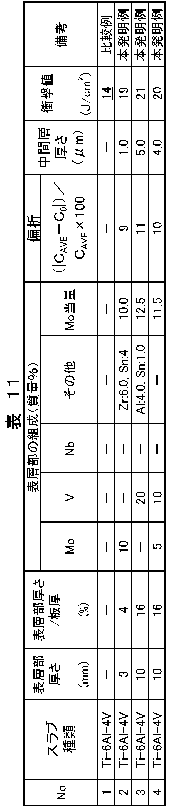
No.1は、表層部(合金濃化層)を形成しない場合であり、水素環境に暴露後の衝撃値は14J/cm2と低い。
No.2~4は、表層部の厚みとMo当量が本発明の範囲であり、水素環境に暴露後の衝撃値も15J/cm2以上であり高い。
(実施例4-3)
母材となるスラブに、真空アーク溶解、鍛造、切削の工程で作製した純チタン2種の70mm厚を用いた。このチタンスラブを用いて、スラブ表面にMoの合金元素素材を散布し、溶融再凝固させて、スラブ表層全面に合金元素が固溶した領域(表層部)を深さ3~10mm形成させた。
母材となるスラブに、真空アーク溶解、鍛造、切削の工程で作製した純チタン2種の70mm厚を用いた。このチタンスラブを用いて、スラブ表面にMoの合金元素素材を散布し、溶融再凝固させて、スラブ表層全面に合金元素が固溶した領域(表層部)を深さ3~10mm形成させた。
当該スラブを850℃に加熱し、厚さ4.8~5.0mmまで熱間圧延した後に、真空雰囲気で、600~650℃、4~10時間の焼鈍を施した。次いで、ショットブラストおよび硝ふっ酸を用いて、表裏面ともデスケーリング処理を行った。
上記で製造した各チタン板を、水素吸収環境である1体積%H2+99体積%Ar雰囲気で500℃、5時間暴露した。
各チタン板の表層3,4の合金元素濃度は、EPMAを用いて、表面から合金濃化部の下端までの範囲を線分析した結果の平均値である。残部は、OやCなどのコンタミ成分を除いて、工業用純チタンに含まれる成分である。
各チタン板から、板厚(4.8~5.0mm)×10mm×55mm、2mmVノッチの衝撃試験片を作製した。試験片の長手方向を圧延方向とし、ノッチの方向は板厚貫通方向とした。水素脆性は衝撃値で評価した。
表層に溶融層を形成していないチタン板を、水素環境に暴露しないで衝撃値を評価すると、2.7J/cm2であった。その値から、30%以上低下した1.9J/cm2以下の場合を水素脆化の基準として、不合格と判定した。
上記の結果を表12にまとめて示す。

No.1~3は、表層部の厚みとMo当量が本発明の範囲であり、水素環境に暴露後の衝撃値も15J/cm2以上であり高い。
(実施例5-1)
以下、添付図面および実施例を参照しながら、本発明をさらに具体的に説明する。
図3に示す、本発明に係る二層構造のチタン複合材である中性子線遮蔽板1は、母材の片側表面を溶融再凝固させた後に熱間圧延されることにより、表層3および内層5を形成される。また、図4に示す、本発明に係る三層構造の中性子線遮蔽板2は、母材の両側表面を溶融再凝固させた後に熱間圧延されることにより、表層3,4および内層5を形成される。中性子線遮蔽板1,2の製造方法を具体的に説明する。
以下、添付図面および実施例を参照しながら、本発明をさらに具体的に説明する。
図3に示す、本発明に係る二層構造のチタン複合材である中性子線遮蔽板1は、母材の片側表面を溶融再凝固させた後に熱間圧延されることにより、表層3および内層5を形成される。また、図4に示す、本発明に係る三層構造の中性子線遮蔽板2は、母材の両側表面を溶融再凝固させた後に熱間圧延されることにより、表層3,4および内層5を形成される。中性子線遮蔽板1,2の製造方法を具体的に説明する。
表13に実施例(本発明例)として示す中性子線遮蔽板1,2は、次の方法で製造される。

まず、素材となるチタンインゴットは、電子ビーム溶解(EB溶解)、プラズマアーク溶解(プラズマ溶解)により矩形鋳型を用いて、または、VAR溶解により円筒鋳型を用いて、それぞれ製造した。
インゴットのサイズは、円柱インゴットが直径1200mm×長さ2500mm、矩形インゴットが厚さ100mm×幅1000mm×長さ4500mmであり、品種は、Ti-1Fe-0.35O、Ti-0.5Cu、Ti-1Cu、Ti-1Cu-0.5Nb、Ti-5Al-1Fe、Ti-3Al-2.5V、Ti-3Al-5Vとした。
鋳造されたインゴットの殆どは、分塊圧延後、切削を行い、溶融再凝固を実施した。その他のインゴットは、そのまま、もしくは、インゴット表面の鋳肌を切削した後、溶融再凝固を行った。
溶融再凝固処理は、少なくとも圧延面の一方について行い、必要に応じて長手方向の側面にも実施した。この処理は、約3×10⁻³Torrの真空雰囲気下で電子ビーム溶接にて行い、溶融時にTiB2粉末(100μm以下)、Ti-B合金チップ(2mm角、1mm厚)、Ti-B合金ワイヤー(φ5mm以下)、Ti-B合金薄膜(20μm以下)、Ti-B合金メッシュ(φ1mmを格子状に組み合わせたもの)のいずれかを添加し、表層部(溶融再凝固層)をTi-0.1~3.2%B合金とすることで、二層構造または三層構造のチタンスラブとした。表層部(B濃化層)については、チタン複合材1での全厚さに占める片面あたりの割合を表13に示しており、三層構造においては、両表面のB濃化層が同じ厚みになるように調整した。
各種素材を添加する際は、スラブ全体に均一に添加されるように、Bを含有する素材を、チタン鋳片の圧延面全体に均一に分散させ、溶融再凝固処理を行った。なお、溶融再凝固処理後に100℃以上500℃未満での1時間以上保持を行った。
溶融再凝固したチタンスラブについて、鉄鋼設備を用い、800℃で240分間加熱後、熱間圧延を行い、厚さ約4mmの帯状コイルを製造した。なお、熱間圧延後の帯状コイルは、硝フッ酸からなる連続酸洗ラインを通板してデスケーリング処理し、その後、割れの発生状況について目視観察を行った。
なお、表層部(B濃化層)の深さの測定方法は、スラブの一部(長手方向の先端、中央、後端の3箇所について、幅方向中央部からそれぞれ採取)を切り出し、研磨したものを、SEM/EDS分析し、板厚に対するB濃化層の割合とB濃化層のB濃度を求めた(観察箇所の中の平均値を採用した)。
また、長手方向の先端、中央、後端の3箇所について、幅方向中央部からL方向の曲げ試験片を計20本採取し、JIS Z 2248(金属材料曲げ試験方法)に準拠して、曲げ試験を行った。試験温度は室温とし、3点曲げ試験により、120度までの曲げ角度で曲げ試験を行い、割れの発生有無を評価し、割れ発生率を求めた。
また、中性子線遮蔽効果の評価は、線源としてAm-Be(4.5MeV)を用いて、線源から200mmの位置に500mm×500mm×4mm厚の試験片を固定した。検出器は、線源から300mmの位置に設置し、対象エネルギーのピーク値を、対照試験片のTi-1Fe-0.35Oと試験片で放射線当量をそれぞれ測定し、その値の比から、中性子線遮蔽効果を評価した(Ti-1Fe-0.35Oの中性子線遮蔽効果を1として、各試験片の値を記載した)。
結果を試験条件とともに表13にまとめて示す。
表13におけるNo.1~9の比較例および実施例は、Ti-1Fe-0.35OのVARインゴットを分塊圧延した後表面を切削して使用した場合である。 No.1の比較例は、溶融再凝固時にBを含有する素材を添加しなかった場合である。熱延板に割れは発生せず、曲げ試験でも割れは発生しなかった。
No.3~5の比較例および実施例は、溶融再凝固時にBを含有する素材としてTiB2を添加した場合である。
No.3の比較例は、表層部の厚み比率が40%を超えた場合である。熱延板には部分的に割れが発生しており、曲げ試験でも割れ発生率が高かった。
No.4~9の実施例(本発明例)は、溶融再凝固時には、B含有素材として、種々素材を用いた場合である。さらに、層構造、表層部の厚さやB濃度をそれぞれ変えて評価した場合である。表層部の厚さ比率が5~40%であり、かつ、表層部のB濃度が0.1~3.0%であるため、いずれも熱延板には割れが発生しておらず、曲げ試験でも割れが発生しなかった。No.10~15の実施例は、Ti-1Fe-0.35OのEB溶解インゴットを使用した場合であり、インゴット鋳造後の製造履歴を変化させている。また、溶融再凝固時には、B含有素材として、種々素材を用い、層構造、表層部の厚さやB濃度をそれぞれ変えて評価した場合である。なお、本実施例では長手方向の側面についても圧延面と同様に溶融再凝固処理を行っている。表層部の厚さ比率が5~40%であり、かつ、表層部のB濃度が0.1~3.0%であるため、いずれも熱延板には割れが発生しておらず、曲げ試験でも割れが発生しなかった。
No.16~21の実施例は、Ti-1Fe-0.35Oのプラズマ溶解インゴットを使用した場合であり、インゴット鋳造後の製造履歴を変化させている。また、溶融再凝固時には、B含有素材として、種々素材を用い、層構造、表層部の厚さやB濃度をそれぞれ変えて評価した場合である。表層部の厚さ比率が5~40%であり、かつ、表層部の厚さのB濃度が0.1~3.0%であるため、いずれも熱延板には割れが発生しておらず、曲げ試験でも割れが発生しなかった。
No.22~33の実施例は、各種チタン合金のVARインゴットを分塊圧延した後表面を切削して使用しており、溶融再凝固時には、B含有素材として、TiB2粉末を用いた場合である。さらに、内層5として各種チタン合金を使用し、層構造、表層部の厚さやB濃度をそれぞれ変えて評価した場合である。表層部の厚さ比率が5~40%であり、かつ、表層部の厚さのB濃度が0.1~3.0%であるため、いずれも熱延板には割れが発生しておらず、曲げ試験でも割れが発生しなかった。
本発明例で内層5に用いた合金は、事前に1.5mm厚のJIS13B試験片で引張試験を行ったところ、0.2%耐力は1000MPa以下であった。
また、No.4~33の実施例(本発明例)では、いずれも中性子遮蔽効果が1以上であり、中性子線遮蔽効果を確認することができた。
なお、核燃料保管用ラックに使用されているB含有量が0.5質量%であるステンレス鋼板(4mm厚)では、中性子遮蔽効果は23.7であり、No.5,11,15,17,21,23の実施例でこのステンレス鋼板よりも高い中性子線遮蔽効果が得られた。
(実施例5-2)
素材となるチタンインゴットは、VAR溶解により円筒鋳型を用いて製造した。
インゴットのサイズは、直径1200mm×長さ2500mmであり、品種は、Ti-1Fe-0.35O、Ti-0.5Cu、Ti-1Cu、Ti-1Cu-0.5Nb、Ti-5Al-1Fe、Ti-3Al-2.5V、Ti-3Al-5Vとした。
素材となるチタンインゴットは、VAR溶解により円筒鋳型を用いて製造した。
インゴットのサイズは、直径1200mm×長さ2500mmであり、品種は、Ti-1Fe-0.35O、Ti-0.5Cu、Ti-1Cu、Ti-1Cu-0.5Nb、Ti-5Al-1Fe、Ti-3Al-2.5V、Ti-3Al-5Vとした。
鋳造されたインゴットは、分塊圧延後、切削を行い、溶融再凝固を行った。
溶融再凝固処理は、少なくとも圧延面の一方について行い、必要に応じて長手方向の側面にも実施した。この処理は、約3×10⁻³Torrの真空雰囲気下で電子ビーム溶接にて行い、溶融時にTiB2粉末(100μm以下)を添加し、溶融再凝固層をTi-0.1~3.7%B合金とすることで、二層構造または三層構造のチタンスラブとした。表層部(B濃化層)については、チタン複合材1での全厚さに占める片面あたりの割合を表14に示しており、三層構造においては、両表面の表層部が同じ厚みになるように調整した。
溶融再凝固処理は、少なくとも圧延面の一方について行い、必要に応じて長手方向の側面にも実施した。この処理は、約3×10⁻³Torrの真空雰囲気下で電子ビーム溶接にて行い、溶融時にTiB2粉末(100μm以下)を添加し、溶融再凝固層をTi-0.1~3.7%B合金とすることで、二層構造または三層構造のチタンスラブとした。表層部(B濃化層)については、チタン複合材1での全厚さに占める片面あたりの割合を表14に示しており、三層構造においては、両表面の表層部が同じ厚みになるように調整した。
各種素材を添加する際は、スラブ全体に均一に添加されるように、Bを含有する素材を、チタン鋳片の圧延面全体に均一に分散させ、溶融再凝固処理を行った。なお、溶融再凝固処理後に100℃以上500℃未満での1時間以上保持を行った。
溶融再凝固したチタンスラブについて、鉄鋼設備を用い、800℃で240分間加熱後、熱間圧延を行い、厚さ約10mmの帯状コイルを製造した。なお、熱間圧延後の帯状コイルは、硝フッ酸からなる連続酸洗ラインを通板してデスケーリング処理し、片面あたり約50μm溶削し、その後、割れの発生状況について目視観察を行った。
なお、表層部(B濃化層)の深さの測定方法は、スラブの一部(長手方向の先端、中央、後端の3箇所について、幅方向中央部からそれぞれ採取)を切り出し、研磨したものを、SEM/EDS分析し、板厚に対するB濃化層の割合とB濃化層のB濃度を求めた(観察箇所の中の平均値を採用した)。
また、長手方向の先端、中央、後端の3箇所について、幅方向中央部からL方向の曲げ試験片を計20本採取し、JIS Z 2248(金属材料曲げ試験方法)に準拠して、曲げ試験を行った。試験温度は室温とし、3点曲げ試験により、120度までの曲げ角度で曲げ試験を行い、割れの発生有無を評価し、割れ発生率を求めた。
また、中性子線遮蔽効果の評価は、線源としてAm-Be(4.5MeV)を用いて、線源から200mmの位置に500mm×500mm×10mm厚の試験片を固定した。検出器は、線源から300mmの位置に設置し、対象エネルギーのピーク値を、対照試験片のTi-1Fe-0.35Oと試験片で放射線当量をそれぞれ測定し、その値の比から、中性子線遮蔽効果を評価した(Ti-1Fe-0.35Oの中性子線遮蔽効果を1として、各試験片の値を記載した)。
結果を試験条件とともに表14にまとめて示す。

表14におけるNo.34,36の比較例は、Ti-1Fe-0.35Oを用いた場合である。No.34の比較例は、溶融再凝固時にBを含有する素材を添加しなかった場合である。熱延板に割れは発生せず、曲げ試験でも割れは発生しなかった。
No.36の比較例は、表層部の厚さ比率が40%を超えた場合である。熱延板には部分的に割れが発生しており、曲げ試験でも割れ発生率が高かった。
また、No.37~50の実施例(本発明例)では、いずれも中性子遮蔽効果が1以上であり、中性子線遮蔽効果を確認することができた。
(実施例5-3)
実施例5-2と同様の手順で、溶融再凝固したチタンスラブについて、鉄鋼設備を用い、800℃で240分間加熱後、熱間圧延を行い、厚さ約5mmの帯状コイルを製造した。なお、熱間圧延後の帯状コイルは、硝フッ酸からなる連続酸洗ラインを通板してデスケーリング処理した。さらに冷間圧延を行い、厚さ4mmのチタン板とし、焼鈍処理として、真空あるいは不活性ガス雰囲気中で600~750℃まで加熱し、240分間保持する熱処理を行った。冷延板は、焼鈍後の表面検査工程で、目視にて割れの発生状況を観察した。
実施例5-2と同様の手順で、溶融再凝固したチタンスラブについて、鉄鋼設備を用い、800℃で240分間加熱後、熱間圧延を行い、厚さ約5mmの帯状コイルを製造した。なお、熱間圧延後の帯状コイルは、硝フッ酸からなる連続酸洗ラインを通板してデスケーリング処理した。さらに冷間圧延を行い、厚さ4mmのチタン板とし、焼鈍処理として、真空あるいは不活性ガス雰囲気中で600~750℃まで加熱し、240分間保持する熱処理を行った。冷延板は、焼鈍後の表面検査工程で、目視にて割れの発生状況を観察した。
なお、表層部(B濃化層)の深さの測定方法は、スラブの一部(長手方向の先端、中央、後端の3箇所について、幅方向中央部からそれぞれ採取)を切り出し、研磨したものを、SEM/EDS分析し、板厚に対するB濃化層の割合とB濃化層のB濃度を求めた(観察箇所の中の平均値を採用した)。
また、長手方向の先端、中央、後端の3箇所について、幅方向中央部からL方向の曲げ試験片を計20本採取し、JIS Z 2248(金属材料曲げ試験方法)に準拠して、曲げ試験を行った。試験温度は室温とし、3点曲げ試験により、120度までの曲げ角度で曲げ試験を行い、割れの発生有無を評価し、割れ発生率を求めた。
また、中性子線遮蔽効果の評価は、線源としてAm-Be(4.5MeV)を用いて、線源から200mmの位置に500mm×500mm×4mm厚の試験片を固定した。検出器は、線源から300mmの位置に設置し、対象エネルギーのピーク値を、対照試験片のTi-1Fe-0.35Oと試験片で放射線当量をそれぞれ測定し、その値の比から、中性子線遮蔽効果を評価した(Ti-1Fe-0.35Oの中性子線遮蔽効果を1として、各試験片の値を記載した)。
結果を試験条件とともに表15にまとめて示す。

表15において、No.51の比較例は、溶融再凝固時にBを含有する素材を添加しなかった場合である。熱延板に割れは発生せず、曲げ試験でも割れは発生しなかった。
No.53の比較例は、表層部の厚さ比率が40%を超えた場合である。熱延板には部分的に割れが発生しており、曲げ試験でも割れ発生率が高かった。
No.54~67の実施例は、内層5として各種チタン合金を使用し、層構造、表層部の厚さやB濃度をそれぞれ変えて評価した場合である。表層部の厚さ比率が5~40%であり、かつ、表層部のB濃度が0.1~3.0%であるため、いずれも熱延板には割れが発生しておらず、曲げ試験でも割れが発生しなかった。
また、No.54~67の実施例(本発明例)では、いずれも中性子遮蔽効果が1以上であり、中性子線遮蔽効果を確認することができた。
(実施例5-4)
実施例5-2と同様の手順で、溶融再凝固したチタンスラブについて、鉄鋼設備を用い、800℃で240分間加熱後、熱間圧延を行い、厚さ約10mmの帯状コイルを製造した。なお、熱間圧延後の帯状コイルは、硝フッ酸からなる連続酸洗ラインを通板してデスケーリング処理し、片面あたり約50μm溶削し、その後、割れの発生状況について目視観察を行った。
実施例5-2と同様の手順で、溶融再凝固したチタンスラブについて、鉄鋼設備を用い、800℃で240分間加熱後、熱間圧延を行い、厚さ約10mmの帯状コイルを製造した。なお、熱間圧延後の帯状コイルは、硝フッ酸からなる連続酸洗ラインを通板してデスケーリング処理し、片面あたり約50μm溶削し、その後、割れの発生状況について目視観察を行った。
なお、表層部(B濃化層)の深さの測定方法は、スラブの一部(長手方向の先端、中央、後端の3箇所について、幅方向中央部からそれぞれ採取)を切り出し、研磨したものを、SEM/EDS分析し、板厚に対するB濃化層の割合とB濃化層のB濃度を求めた(観察箇所の中の平均値を採用した)。
また、長手方向の先端、中央、後端の3箇所について、幅方向中央部からL方向の曲げ試験片を計20本採取し、JIS Z 2248(金属材料曲げ試験方法)に準拠して、曲げ試験を行った。試験温度は室温とし、3点曲げ試験により、120度までの曲げ角度で曲げ試験を行い、割れの発生有無を評価し、割れ発生率を求めた。
また、中性子線遮蔽効果の評価は、線源としてAm-Be(4.5MeV)を用いて、線源から200mmの位置に500mm×500mm×10mm厚の試験片を固定した。検出器は、線源から300mmの位置に設置し、対象エネルギーのピーク値を、対照試験片のTi-1Fe-0.35Oと試験片で放射線当量をそれぞれ測定し、その値の比から、中性子線遮蔽効果を評価した(Ti-1Fe-0.35Oの中性子線遮蔽効果を1として、各試験片の値を記載した)。
結果を試験条件とともに表16にまとめて示す。

No.68~70の実施例は、内層5として各種チタン合金を使用し、層構造、表層部の厚さやB濃度をそれぞれ変えて評価した場合である。表層部の厚さ比率が5~40%であり、かつ、表層部のB濃度が0.1~3.0%であるため、いずれも熱延板には割れが発生しておらず、曲げ試験でも割れが発生しなかった。
また、No.68~70の実施例(本発明例)では、いずれも中性子遮蔽効果が1以上であり、中性子線遮蔽効果を確認することができた。
1.熱間圧延用チタン材
1a,1aa,1ab.表層部
1b.母材
2.チタン複合材
3,4.表層(表面層)
5.内層
1a,1aa,1ab.表層部
1b.母材
2.チタン複合材
3,4.表層(表面層)
5.内層
Claims (7)
- 工業用純チタンまたはチタン合金からなる母材と、
前記母材の少なくとも一方の圧延面に形成された前記母材とは異なる化学組成を有する表層部と、を備える熱間圧延用チタン材であって、
前記表層部が、その厚さが2.0~20.0mm、全厚さに占める割合が片面あたり40%以下であり、
前記表層部に含まれる元素の含有量を複数点測定したとき、母材からの増加含有量の平均値CAVEと各測定箇所における母材からの増加含有量C0との関係:|CAVE-C0|/CAVE×100が40%以下である、
熱間圧延用チタン材。 - 前記表層部の化学組成が、質量%で、
白金族元素:0.01~0.25%、
希土類元素:0~0.2%、
Co:0~0.8%、
Ni:0~0.6%、
残部:チタンおよび不純物である、
請求項1に記載の熱間圧延用チタン材。 - 前記白金族元素が、Pdおよび/またはRuである、
請求項2に記載の熱間圧延用チタン材。 - 前記化学組成が、質量%で、
希土類元素:0.001~0.2%、を含有する、
請求項2または請求項3に記載の熱間圧延用チタン材。 - 前記化学組成が、質量%で、
Co:0.05~0.8%、および、
Ni:0.05~0.6%、
から選択される1種以上を含有する、
請求項2から請求項4までのいずれかに記載の熱間圧延用チタン材。 - 前記工業用純チタンの化学組成が、質量%で、
C:0.1%以下、
H:0.015%以下、
O:0.4%以下、
N:0.07%以下、
Fe:0.5%以下、
残部:Tiおよび不純物である、
請求項2から請求項5までのいずれかに記載の熱間圧延用チタン材。 - 前記母材の圧延面以外の面に、他の表層部が形成されており、
前記他の表層部が、前記表層部と同一の化学組成および金属組織を備える、
請求項1から請求項6までのいずれかに記載の熱間圧延用チタン材。
Priority Applications (1)
| Application Number | Priority Date | Filing Date | Title |
|---|---|---|---|
| JP2017530937A JPWO2017018511A1 (ja) | 2015-07-29 | 2016-07-29 | 熱間圧延用チタン材 |
Applications Claiming Priority (2)
| Application Number | Priority Date | Filing Date | Title |
|---|---|---|---|
| JP2015-149392 | 2015-07-29 | ||
| JP2015149392 | 2015-07-29 |
Publications (1)
| Publication Number | Publication Date |
|---|---|
| WO2017018511A1 true WO2017018511A1 (ja) | 2017-02-02 |
Family
ID=57884450
Family Applications (1)
| Application Number | Title | Priority Date | Filing Date |
|---|---|---|---|
| PCT/JP2016/072333 WO2017018511A1 (ja) | 2015-07-29 | 2016-07-29 | 熱間圧延用チタン材 |
Country Status (3)
| Country | Link |
|---|---|
| JP (2) | JPWO2017018511A1 (ja) |
| TW (1) | TWI605129B (ja) |
| WO (1) | WO2017018511A1 (ja) |
Cited By (7)
| Publication number | Priority date | Publication date | Assignee | Title |
|---|---|---|---|---|
| CN108179315A (zh) * | 2017-12-29 | 2018-06-19 | 佛山科学技术学院 | 一种钛合金 |
| WO2019082352A1 (ja) * | 2017-10-26 | 2019-05-02 | 日本製鉄株式会社 | チタン熱間圧延板の製造方法 |
| JP2021523295A (ja) * | 2018-05-07 | 2021-09-02 | エイティーアイ・プロパティーズ・エルエルシー | 高強度チタン合金 |
| US11268179B2 (en) | 2018-08-28 | 2022-03-08 | Ati Properties Llc | Creep resistant titanium alloys |
| US11384413B2 (en) | 2018-04-04 | 2022-07-12 | Ati Properties Llc | High temperature titanium alloys |
| WO2022185409A1 (ja) * | 2021-03-02 | 2022-09-09 | 日本製鉄株式会社 | 熱間加工用α+β型チタン合金鋳塊 |
| CN116651937A (zh) * | 2023-07-31 | 2023-08-29 | 海安太原理工大学先进制造与智能装备产业研究院 | 一种大厚比镁/钛复合板及梯度异温轧制复合方法 |
Families Citing this family (4)
| Publication number | Priority date | Publication date | Assignee | Title |
|---|---|---|---|---|
| JP6935254B2 (ja) * | 2017-07-10 | 2021-09-15 | 日本信号株式会社 | 駆動装置 |
| TWI750748B (zh) * | 2020-07-27 | 2021-12-21 | 日商日本製鐵股份有限公司 | 金屬箔製造用鈦材及金屬箔製造用鈦材之製造方法及金屬箔製造滾筒 |
| WO2024019408A1 (ko) * | 2022-07-19 | 2024-01-25 | 한국원자력연구원 | 우수한 중성자흡수능과 인장특성을 갖는 티타늄-가돌리늄계 합금의 합금조성 및 이를 통해 제조한 중성자흡수 구조재 |
| CN115652141B (zh) * | 2022-11-18 | 2023-09-01 | 厦门九牧研发有限公司 | 一种低成本易切削抗菌钛合金及钛合金龙头的制备方法 |
Citations (3)
| Publication number | Priority date | Publication date | Assignee | Title |
|---|---|---|---|---|
| US5579988A (en) * | 1995-06-09 | 1996-12-03 | Rmi Titanium Company | Clad reactive metal plate product and process for producing the same |
| WO2013014894A1 (ja) * | 2011-07-26 | 2013-01-31 | 新日鐵住金株式会社 | チタン合金 |
| WO2014163087A1 (ja) * | 2013-04-01 | 2014-10-09 | 新日鐵住金株式会社 | 熱間圧延用チタン鋳片およびその製造方法 |
Family Cites Families (2)
| Publication number | Priority date | Publication date | Assignee | Title |
|---|---|---|---|---|
| JP3500072B2 (ja) * | 1998-07-27 | 2004-02-23 | 新日本製鐵株式会社 | 電解金属箔製造ドラム用チタン材およびその製造方法 |
| JP3802683B2 (ja) * | 1998-07-27 | 2006-07-26 | 新日本製鐵株式会社 | チタンターゲット材用高純度チタン板およびその製造方法 |
-
2016
- 2016-07-29 TW TW105124180A patent/TWI605129B/zh not_active IP Right Cessation
- 2016-07-29 JP JP2017530937A patent/JPWO2017018511A1/ja active Pending
- 2016-07-29 WO PCT/JP2016/072333 patent/WO2017018511A1/ja active Application Filing
-
2019
- 2019-02-12 JP JP2019022696A patent/JP6787418B2/ja active Active
Patent Citations (3)
| Publication number | Priority date | Publication date | Assignee | Title |
|---|---|---|---|---|
| US5579988A (en) * | 1995-06-09 | 1996-12-03 | Rmi Titanium Company | Clad reactive metal plate product and process for producing the same |
| WO2013014894A1 (ja) * | 2011-07-26 | 2013-01-31 | 新日鐵住金株式会社 | チタン合金 |
| WO2014163087A1 (ja) * | 2013-04-01 | 2014-10-09 | 新日鐵住金株式会社 | 熱間圧延用チタン鋳片およびその製造方法 |
Cited By (17)
| Publication number | Priority date | Publication date | Assignee | Title |
|---|---|---|---|---|
| EA039472B1 (ru) * | 2017-10-26 | 2022-01-31 | Ниппон Стил Корпорейшн | Способ производства горячекатаной титановой плиты |
| JPWO2019082352A1 (ja) * | 2017-10-26 | 2020-10-22 | 日本製鉄株式会社 | チタン熱間圧延板の製造方法 |
| KR20200070358A (ko) * | 2017-10-26 | 2020-06-17 | 닛폰세이테츠 가부시키가이샤 | 티탄 열간 압연판의 제조 방법 |
| KR102332457B1 (ko) * | 2017-10-26 | 2021-12-01 | 닛폰세이테츠 가부시키가이샤 | 티탄 열간 압연판의 제조 방법 |
| WO2019082352A1 (ja) * | 2017-10-26 | 2019-05-02 | 日本製鉄株式会社 | チタン熱間圧延板の製造方法 |
| CN111278581B (zh) * | 2017-10-26 | 2021-10-01 | 日本制铁株式会社 | 钛热轧板的制造方法 |
| CN111278581A (zh) * | 2017-10-26 | 2020-06-12 | 日本制铁株式会社 | 钛热轧板的制造方法 |
| CN108179315A (zh) * | 2017-12-29 | 2018-06-19 | 佛山科学技术学院 | 一种钛合金 |
| US11384413B2 (en) | 2018-04-04 | 2022-07-12 | Ati Properties Llc | High temperature titanium alloys |
| JP2021523295A (ja) * | 2018-05-07 | 2021-09-02 | エイティーアイ・プロパティーズ・エルエルシー | 高強度チタン合金 |
| JP7221988B2 (ja) | 2018-05-07 | 2023-02-14 | エイティーアイ・プロパティーズ・エルエルシー | 高強度チタン合金 |
| US11674200B2 (en) | 2018-05-07 | 2023-06-13 | Ati Properties Llc | High strength titanium alloys |
| US11268179B2 (en) | 2018-08-28 | 2022-03-08 | Ati Properties Llc | Creep resistant titanium alloys |
| US11920231B2 (en) | 2018-08-28 | 2024-03-05 | Ati Properties Llc | Creep resistant titanium alloys |
| WO2022185409A1 (ja) * | 2021-03-02 | 2022-09-09 | 日本製鉄株式会社 | 熱間加工用α+β型チタン合金鋳塊 |
| CN116651937A (zh) * | 2023-07-31 | 2023-08-29 | 海安太原理工大学先进制造与智能装备产业研究院 | 一种大厚比镁/钛复合板及梯度异温轧制复合方法 |
| CN116651937B (zh) * | 2023-07-31 | 2023-10-13 | 海安太原理工大学先进制造与智能装备产业研究院 | 一种大厚比镁/钛复合板及梯度异温轧制复合方法 |
Also Published As
| Publication number | Publication date |
|---|---|
| JPWO2017018511A1 (ja) | 2018-01-25 |
| JP6787418B2 (ja) | 2020-11-18 |
| JP2019115933A (ja) | 2019-07-18 |
| TWI605129B (zh) | 2017-11-11 |
| TW201715050A (zh) | 2017-05-01 |
Similar Documents
| Publication | Publication Date | Title |
|---|---|---|
| JP6658756B2 (ja) | チタン複合材および熱間圧延用チタン材 | |
| JP6787418B2 (ja) | 熱間圧延用チタン材 | |
| JP6172405B2 (ja) | チタン複合材および熱間加工用チタン材 | |
| JP6515358B2 (ja) | チタン複合材および熱間圧延用チタン材 | |
| WO2017018514A1 (ja) | チタン複合材および熱間圧延用チタン材 | |
| JP6128289B1 (ja) | チタン複合材および熱間圧延用チタン材 | |
| WO2017018515A1 (ja) | 熱間圧延用チタン材 | |
| JP6086178B1 (ja) | 熱間圧延用チタン材 | |
| JP6137423B1 (ja) | チタン複合材および熱間圧延用チタン材 | |
| JP6515357B2 (ja) | 熱間圧延用チタン材 | |
| WO2017018523A1 (ja) | 熱間圧延用チタン材 |
Legal Events
| Date | Code | Title | Description |
|---|---|---|---|
| 121 | Ep: the epo has been informed by wipo that ep was designated in this application |
Ref document number: 16830614 Country of ref document: EP Kind code of ref document: A1 |
|
| ENP | Entry into the national phase |
Ref document number: 2017530937 Country of ref document: JP Kind code of ref document: A |
|
| NENP | Non-entry into the national phase |
Ref country code: DE |
|
| 122 | Ep: pct application non-entry in european phase |
Ref document number: 16830614 Country of ref document: EP Kind code of ref document: A1 |